EP3141436A1 - Vehicle having at least one standing place for a standing driver and/or a standing passenger - Google Patents
Vehicle having at least one standing place for a standing driver and/or a standing passenger Download PDFInfo
- Publication number
- EP3141436A1 EP3141436A1 EP16188034.9A EP16188034A EP3141436A1 EP 3141436 A1 EP3141436 A1 EP 3141436A1 EP 16188034 A EP16188034 A EP 16188034A EP 3141436 A1 EP3141436 A1 EP 3141436A1
- Authority
- EP
- European Patent Office
- Prior art keywords
- vehicle
- standing
- driver
- collecting
- passenger
- Prior art date
- Legal status (The legal status is an assumption and is not a legal conclusion. Google has not performed a legal analysis and makes no representation as to the accuracy of the status listed.)
- Granted
Links
- 230000005484 gravity Effects 0.000 claims description 7
- 239000000463 material Substances 0.000 claims description 4
- 210000000323 shoulder joint Anatomy 0.000 claims description 3
- 210000001562 sternum Anatomy 0.000 claims description 2
- 230000000452 restraining effect Effects 0.000 abstract description 3
- 230000035939 shock Effects 0.000 abstract description 2
- 230000000694 effects Effects 0.000 description 6
- 230000001133 acceleration Effects 0.000 description 5
- 230000002829 reductive effect Effects 0.000 description 5
- 238000000034 method Methods 0.000 description 4
- 238000010521 absorption reaction Methods 0.000 description 3
- 230000003111 delayed effect Effects 0.000 description 3
- NJPPVKZQTLUDBO-UHFFFAOYSA-N novaluron Chemical compound C1=C(Cl)C(OC(F)(F)C(OC(F)(F)F)F)=CC=C1NC(=O)NC(=O)C1=C(F)C=CC=C1F NJPPVKZQTLUDBO-UHFFFAOYSA-N 0.000 description 3
- 230000008569 process Effects 0.000 description 3
- 208000027418 Wounds and injury Diseases 0.000 description 2
- 210000001015 abdomen Anatomy 0.000 description 2
- 230000003750 conditioning effect Effects 0.000 description 2
- 238000010276 construction Methods 0.000 description 2
- 230000006378 damage Effects 0.000 description 2
- 230000007423 decrease Effects 0.000 description 2
- 230000001934 delay Effects 0.000 description 2
- 238000010586 diagram Methods 0.000 description 2
- 239000006260 foam Substances 0.000 description 2
- 208000014674 injury Diseases 0.000 description 2
- 210000002414 leg Anatomy 0.000 description 2
- 230000033001 locomotion Effects 0.000 description 2
- 210000003141 lower extremity Anatomy 0.000 description 2
- 230000000717 retained effect Effects 0.000 description 2
- 230000007704 transition Effects 0.000 description 2
- 206010039203 Road traffic accident Diseases 0.000 description 1
- 230000008901 benefit Effects 0.000 description 1
- 210000000746 body region Anatomy 0.000 description 1
- 210000000481 breast Anatomy 0.000 description 1
- 210000001217 buttock Anatomy 0.000 description 1
- 150000001875 compounds Chemical class 0.000 description 1
- 230000006835 compression Effects 0.000 description 1
- 238000007906 compression Methods 0.000 description 1
- 230000008030 elimination Effects 0.000 description 1
- 238000003379 elimination reaction Methods 0.000 description 1
- 230000010006 flight Effects 0.000 description 1
- 238000007654 immersion Methods 0.000 description 1
- 230000003116 impacting effect Effects 0.000 description 1
- 238000009434 installation Methods 0.000 description 1
- 238000012423 maintenance Methods 0.000 description 1
- 230000014759 maintenance of location Effects 0.000 description 1
- 238000000465 moulding Methods 0.000 description 1
- 210000000056 organ Anatomy 0.000 description 1
- 230000036961 partial effect Effects 0.000 description 1
- 230000001681 protective effect Effects 0.000 description 1
- 230000009467 reduction Effects 0.000 description 1
- 239000012858 resilient material Substances 0.000 description 1
- 230000000276 sedentary effect Effects 0.000 description 1
- 238000004904 shortening Methods 0.000 description 1
- 239000007787 solid Substances 0.000 description 1
- 230000004083 survival effect Effects 0.000 description 1
- 230000001960 triggered effect Effects 0.000 description 1
Images


Classifications
-
- B—PERFORMING OPERATIONS; TRANSPORTING
- B60—VEHICLES IN GENERAL
- B60R—VEHICLES, VEHICLE FITTINGS, OR VEHICLE PARTS, NOT OTHERWISE PROVIDED FOR
- B60R21/00—Arrangements or fittings on vehicles for protecting or preventing injuries to occupants or pedestrians in case of accidents or other traffic risks
- B60R21/02—Occupant safety arrangements or fittings, e.g. crash pads
-
- B—PERFORMING OPERATIONS; TRANSPORTING
- B60—VEHICLES IN GENERAL
- B60N—SEATS SPECIALLY ADAPTED FOR VEHICLES; VEHICLE PASSENGER ACCOMMODATION NOT OTHERWISE PROVIDED FOR
- B60N2/00—Seats specially adapted for vehicles; Arrangement or mounting of seats in vehicles
- B60N2/24—Seats specially adapted for vehicles; Arrangement or mounting of seats in vehicles for particular purposes or particular vehicles
- B60N2/42—Seats specially adapted for vehicles; Arrangement or mounting of seats in vehicles for particular purposes or particular vehicles the seat constructed to protect the occupant from the effect of abnormal g-forces, e.g. crash or safety seats
- B60N2/4207—Seats specially adapted for vehicles; Arrangement or mounting of seats in vehicles for particular purposes or particular vehicles the seat constructed to protect the occupant from the effect of abnormal g-forces, e.g. crash or safety seats characterised by the direction of the g-forces
- B60N2/4214—Seats specially adapted for vehicles; Arrangement or mounting of seats in vehicles for particular purposes or particular vehicles the seat constructed to protect the occupant from the effect of abnormal g-forces, e.g. crash or safety seats characterised by the direction of the g-forces longitudinal
- B60N2/4221—Seats specially adapted for vehicles; Arrangement or mounting of seats in vehicles for particular purposes or particular vehicles the seat constructed to protect the occupant from the effect of abnormal g-forces, e.g. crash or safety seats characterised by the direction of the g-forces longitudinal due to impact coming from the front
-
- B—PERFORMING OPERATIONS; TRANSPORTING
- B60—VEHICLES IN GENERAL
- B60N—SEATS SPECIALLY ADAPTED FOR VEHICLES; VEHICLE PASSENGER ACCOMMODATION NOT OTHERWISE PROVIDED FOR
- B60N2/00—Seats specially adapted for vehicles; Arrangement or mounting of seats in vehicles
- B60N2/24—Seats specially adapted for vehicles; Arrangement or mounting of seats in vehicles for particular purposes or particular vehicles
- B60N2/42—Seats specially adapted for vehicles; Arrangement or mounting of seats in vehicles for particular purposes or particular vehicles the seat constructed to protect the occupant from the effect of abnormal g-forces, e.g. crash or safety seats
- B60N2/4249—Seats specially adapted for vehicles; Arrangement or mounting of seats in vehicles for particular purposes or particular vehicles the seat constructed to protect the occupant from the effect of abnormal g-forces, e.g. crash or safety seats fixed structures, i.e. where neither the seat nor a part thereof are displaced during a crash
-
- B—PERFORMING OPERATIONS; TRANSPORTING
- B60—VEHICLES IN GENERAL
- B60N—SEATS SPECIALLY ADAPTED FOR VEHICLES; VEHICLE PASSENGER ACCOMMODATION NOT OTHERWISE PROVIDED FOR
- B60N2/00—Seats specially adapted for vehicles; Arrangement or mounting of seats in vehicles
- B60N2/24—Seats specially adapted for vehicles; Arrangement or mounting of seats in vehicles for particular purposes or particular vehicles
- B60N2/42—Seats specially adapted for vehicles; Arrangement or mounting of seats in vehicles for particular purposes or particular vehicles the seat constructed to protect the occupant from the effect of abnormal g-forces, e.g. crash or safety seats
- B60N2/427—Seats or parts thereof displaced during a crash
- B60N2/42709—Seats or parts thereof displaced during a crash involving residual deformation or fracture of the structure
-
- B—PERFORMING OPERATIONS; TRANSPORTING
- B60—VEHICLES IN GENERAL
- B60R—VEHICLES, VEHICLE FITTINGS, OR VEHICLE PARTS, NOT OTHERWISE PROVIDED FOR
- B60R21/00—Arrangements or fittings on vehicles for protecting or preventing injuries to occupants or pedestrians in case of accidents or other traffic risks
- B60R21/02—Occupant safety arrangements or fittings, e.g. crash pads
- B60R21/04—Padded linings for the vehicle interior ; Energy absorbing structures associated with padded or non-padded linings
-
- B—PERFORMING OPERATIONS; TRANSPORTING
- B60—VEHICLES IN GENERAL
- B60R—VEHICLES, VEHICLE FITTINGS, OR VEHICLE PARTS, NOT OTHERWISE PROVIDED FOR
- B60R21/00—Arrangements or fittings on vehicles for protecting or preventing injuries to occupants or pedestrians in case of accidents or other traffic risks
- B60R21/02—Occupant safety arrangements or fittings, e.g. crash pads
- B60R21/16—Inflatable occupant restraints or confinements designed to inflate upon impact or impending impact, e.g. air bags
-
- B—PERFORMING OPERATIONS; TRANSPORTING
- B60—VEHICLES IN GENERAL
- B60N—SEATS SPECIALLY ADAPTED FOR VEHICLES; VEHICLE PASSENGER ACCOMMODATION NOT OTHERWISE PROVIDED FOR
- B60N2/00—Seats specially adapted for vehicles; Arrangement or mounting of seats in vehicles
- B60N2/24—Seats specially adapted for vehicles; Arrangement or mounting of seats in vehicles for particular purposes or particular vehicles
- B60N2002/247—Seats specially adapted for vehicles; Arrangement or mounting of seats in vehicles for particular purposes or particular vehicles to support passengers in a half-standing position
-
- B—PERFORMING OPERATIONS; TRANSPORTING
- B60—VEHICLES IN GENERAL
- B60R—VEHICLES, VEHICLE FITTINGS, OR VEHICLE PARTS, NOT OTHERWISE PROVIDED FOR
- B60R21/00—Arrangements or fittings on vehicles for protecting or preventing injuries to occupants or pedestrians in case of accidents or other traffic risks
- B60R2021/003—Arrangements or fittings on vehicles for protecting or preventing injuries to occupants or pedestrians in case of accidents or other traffic risks characterised by occupant or pedestian
- B60R2021/0032—Position of passenger
- B60R2021/0037—Position of passenger standing
-
- B—PERFORMING OPERATIONS; TRANSPORTING
- B60—VEHICLES IN GENERAL
- B60R—VEHICLES, VEHICLE FITTINGS, OR VEHICLE PARTS, NOT OTHERWISE PROVIDED FOR
- B60R21/00—Arrangements or fittings on vehicles for protecting or preventing injuries to occupants or pedestrians in case of accidents or other traffic risks
- B60R21/02—Occupant safety arrangements or fittings, e.g. crash pads
- B60R21/04—Padded linings for the vehicle interior ; Energy absorbing structures associated with padded or non-padded linings
- B60R2021/0407—Padded linings for the vehicle interior ; Energy absorbing structures associated with padded or non-padded linings using gas or liquid as energy absorbing means
-
- B—PERFORMING OPERATIONS; TRANSPORTING
- B60—VEHICLES IN GENERAL
- B60R—VEHICLES, VEHICLE FITTINGS, OR VEHICLE PARTS, NOT OTHERWISE PROVIDED FOR
- B60R21/00—Arrangements or fittings on vehicles for protecting or preventing injuries to occupants or pedestrians in case of accidents or other traffic risks
- B60R21/02—Occupant safety arrangements or fittings, e.g. crash pads
- B60R21/04—Padded linings for the vehicle interior ; Energy absorbing structures associated with padded or non-padded linings
- B60R2021/0442—Padded linings for the vehicle interior ; Energy absorbing structures associated with padded or non-padded linings associated with the roof panel
-
- B—PERFORMING OPERATIONS; TRANSPORTING
- B60—VEHICLES IN GENERAL
- B60R—VEHICLES, VEHICLE FITTINGS, OR VEHICLE PARTS, NOT OTHERWISE PROVIDED FOR
- B60R21/00—Arrangements or fittings on vehicles for protecting or preventing injuries to occupants or pedestrians in case of accidents or other traffic risks
- B60R21/02—Occupant safety arrangements or fittings, e.g. crash pads
- B60R21/16—Inflatable occupant restraints or confinements designed to inflate upon impact or impending impact, e.g. air bags
- B60R21/23—Inflatable members
- B60R21/231—Inflatable members characterised by their shape, construction or spatial configuration
- B60R2021/23169—Inflatable members characterised by their shape, construction or spatial configuration specially adapted for knee protection
-
- B—PERFORMING OPERATIONS; TRANSPORTING
- B60—VEHICLES IN GENERAL
- B60R—VEHICLES, VEHICLE FITTINGS, OR VEHICLE PARTS, NOT OTHERWISE PROVIDED FOR
- B60R21/00—Arrangements or fittings on vehicles for protecting or preventing injuries to occupants or pedestrians in case of accidents or other traffic risks
- B60R21/02—Occupant safety arrangements or fittings, e.g. crash pads
- B60R21/16—Inflatable occupant restraints or confinements designed to inflate upon impact or impending impact, e.g. air bags
- B60R21/23—Inflatable members
- B60R21/231—Inflatable members characterised by their shape, construction or spatial configuration
- B60R2021/23176—Inflatable members characterised by their shape, construction or spatial configuration specially adapted for foot protection
-
- B—PERFORMING OPERATIONS; TRANSPORTING
- B60—VEHICLES IN GENERAL
- B60R—VEHICLES, VEHICLE FITTINGS, OR VEHICLE PARTS, NOT OTHERWISE PROVIDED FOR
- B60R21/00—Arrangements or fittings on vehicles for protecting or preventing injuries to occupants or pedestrians in case of accidents or other traffic risks
- B60R21/02—Occupant safety arrangements or fittings, e.g. crash pads
- B60R21/16—Inflatable occupant restraints or confinements designed to inflate upon impact or impending impact, e.g. air bags
- B60R21/23—Inflatable members
- B60R21/231—Inflatable members characterised by their shape, construction or spatial configuration
- B60R2021/23192—Roof bags, i.e. protecting the occupant in a roll-over situation
-
- B—PERFORMING OPERATIONS; TRANSPORTING
- B60—VEHICLES IN GENERAL
- B60R—VEHICLES, VEHICLE FITTINGS, OR VEHICLE PARTS, NOT OTHERWISE PROVIDED FOR
- B60R21/00—Arrangements or fittings on vehicles for protecting or preventing injuries to occupants or pedestrians in case of accidents or other traffic risks
- B60R21/02—Occupant safety arrangements or fittings, e.g. crash pads
- B60R21/04—Padded linings for the vehicle interior ; Energy absorbing structures associated with padded or non-padded linings
- B60R21/0428—Padded linings for the vehicle interior ; Energy absorbing structures associated with padded or non-padded linings associated with the side doors or panels, e.g. displaced towards the occupants in case of a side collision
-
- B—PERFORMING OPERATIONS; TRANSPORTING
- B60—VEHICLES IN GENERAL
- B60R—VEHICLES, VEHICLE FITTINGS, OR VEHICLE PARTS, NOT OTHERWISE PROVIDED FOR
- B60R21/00—Arrangements or fittings on vehicles for protecting or preventing injuries to occupants or pedestrians in case of accidents or other traffic risks
- B60R21/02—Occupant safety arrangements or fittings, e.g. crash pads
- B60R21/04—Padded linings for the vehicle interior ; Energy absorbing structures associated with padded or non-padded linings
- B60R21/045—Padded linings for the vehicle interior ; Energy absorbing structures associated with padded or non-padded linings associated with the instrument panel or dashboard
-
- B—PERFORMING OPERATIONS; TRANSPORTING
- B60—VEHICLES IN GENERAL
- B60R—VEHICLES, VEHICLE FITTINGS, OR VEHICLE PARTS, NOT OTHERWISE PROVIDED FOR
- B60R21/00—Arrangements or fittings on vehicles for protecting or preventing injuries to occupants or pedestrians in case of accidents or other traffic risks
- B60R21/02—Occupant safety arrangements or fittings, e.g. crash pads
- B60R21/16—Inflatable occupant restraints or confinements designed to inflate upon impact or impending impact, e.g. air bags
- B60R21/23—Inflatable members
- B60R21/231—Inflatable members characterised by their shape, construction or spatial configuration
- B60R21/23138—Inflatable members characterised by their shape, construction or spatial configuration specially adapted for side protection
Definitions
- the invention relates to a vehicle with at least one standing space for a stationary driver and / or a standing passenger, with a front area having at least one impact energy absorbing crumple zone.
- the safety systems commonly used today in road vehicles, in particular seat belts and airbags, are effective only in connection with a seated position of the persons in order to form a coordinated safety system with a deformation area at the front of the vehicle and possibly another deformation area at the rear of the vehicle, the so-called crumple zone.
- a common deceleration of the driver thus secured or of the passengers thus secured takes place together with the vehicle compartment.
- the crumple zones serve to reduce the deceleration forces acting on the occupants. In this way, in modern vehicles, a survival of the vehicle occupants in an impact on an obstacle with a relative speed of about 50 km / h is likely to be assumed.
- the CA 2696407 A1 shows a commercial vehicle in which the driver's seat can be used with raised seat in a normal, sitting position, but the seat can also be folded down so that the driver can control the vehicle in a standing position in a standing position.
- a standing seat for standing passengers carried on public transport is from the DE 198 14 548 C1 known. Again, a little projecting seat allows a standing ajar posture. Transparent blinds in front of and behind the passenger form a restraint system. In the case of heavy braking, the passenger is thrown against the transparent, soft restraint system without seriously injuring himself.
- this system designed for buses is not transferable to other vehicles, in particular it is not suitable for driver's seats, since the driver must have an unobstructed view and unobstructed access to the steering wheel and other controls. It should also be borne in mind that, when in doubt, buses are more likely to be the major accident participant due to their mass and, in any case, are subject to significantly less delays in the event of a collision with a passenger car.
- Stand-operated other vehicles are therefore less used on public roads, but are used in particular for carriage outside are used on public courses on golf courses and are for example in the WO 2006/032275 A2 or JP 62101586 A shown.
- the object of the present invention is thus to allow in a vehicle of the type mentioned a vehicle guidance by a stationary driver and / or a transport of passengers standing or a standing position leaning while at the same time a backup of the driver and / or passengers in the event of an accident.
- This vehicle is based in the basic construction on existing vehicle cells, which have in front of and / or behind the solid parts of the drive train a deformable zone, the so-called crumple zone, which usually also in the event of a rear impact in the rear of the vehicle further deformation range is provided.
- the vehicle according to the invention thus uses the already achieved in the prior art reduction of the forces acting on the human body deceleration forces by structural measures.
- Drivers and passengers are in the vehicle according to the invention, regardless of whether they are freestanding, leaning against a standing seat or driving with an additional foldable seat in half-sitting position, always between a front and a rear catch element, which is resilient and thus not only one fulfilled mechanical restraint function, but in particular shock-absorbing, so energy-consuming.
- the shock absorption or impact absorption goes beyond pure upholstery to reduce the severest injuries at the speeds prevailing in inner city traffic.
- the trapping elements are free of internal, hard stiffening elements to the unobstructed immersion of the body in the collecting elements to the maximum allow elastic compression or maximum soft plastic deformation of the layer (s) in the collecting elements.
- the invention aims to initiate the deceleration of the body largely simultaneously with the passenger compartment, but to decouple it as far as possible from the passenger compartment.
- the body can be braked according to the invention of the other vehicle compartment and the chassis partially independently alone within the resilient collecting elements by its kinetic energy is absorbed by elastic and / or plastic deformation.
- the only connection of the body to the passenger compartment is indirect, since the collecting elements on which it bounces are connected as such to the passenger compartment. The connection is of course only in the areas that do not represent the impact side.
- the deceleration path and hence the deceleration time can be extended. Accordingly, the acceleration acting on the body decreases.
- the body can still move within the resilient foam layers or other layers which form the catching elements when the passenger compartment has already come to a standstill.
- the collecting elements form a very wide collecting surface, which is preferably even wider than the impact surface of the body of the driver or passenger, so that in the event of an impact, the body of the occupant is hurled over the entire surface against the collecting surface and then in the course of the accident against the back catch area is thrown back.
- a point overloading of individual body regions is avoided by the large-area distribution.
- the collecting surfaces extend upwards beyond the center of gravity of the body and preferably end below the shoulder joints so far that at least the driver and possibly also the occupants can place the arms comfortably on the upper side of the collecting elements or on other suitable supporting surfaces.
- the body center of gravity is assumed to be at the level of the upper abdomen, so that the collecting elements should extend at least up to the level of the breast.
- the steering wheel or a bow-shaped handlebar as is common in two-wheelers and quads, is freely accessible according to the invention with the other necessary controls from above the front collecting element. A contact of the driver's upper body with the steering wheel and other controls in an accident is thus avoided even when the driver is thrown to the front collecting surface and there is a strong deformation of the local collecting element.
- the restraint device is designed so that it encloses the upper body of the occupant not only in projected area forward and backward to the direction of travel, but in full.
- the front and the rear collecting element as provided according to the invention minimum equipment are supplemented to a arranged in the middle of the vehicle middle part and expanded to a horseshoe-shaped structure seen from above. The remaining lateral gap in this ring is used for easy entry and exit from the vehicle side.
- a very secure vehicle which also allows fast entry and exit of all occupants and is thus particularly suitable for delivery services, postal delivery and military deployment scenarios, ie for those applications in which a frequent, fast boarding and leaving possible should be.
- the remaining on the entry side opening is preferably closed by an additional catch element which is fixed to the inside of a vehicle door.
- an additional catch element which is fixed to the inside of a vehicle door.
- the vehicle according to the invention since the cost of installation and maintenance and subsequent disposal of sophisticated security systems including sensors and pyrotechnics can be omitted.
- the safety belt itself can be omitted as well as the associated additional systems such as belt tensioners and belt force limiters.
- Even the frontally arranged airbags including the associated sensors are no longer needed at least outside the driver's seat.
- the elimination of the airbags also reduces the risk for accident workers, which can be significantly injured by delayed triggered airbags.
- a load uniformly distributed over the body surface is achieved. Peak loads during the accident are reduced, so that the maximum permissible biomechanical load values are undercut in a normalized, related to the inner city traffic accidents.
- An additional retaining element may be provided to additionally protect the occupants in the event of a vehicle rollover by being held in the all-round secure standing even against vertically acting forces. This can be effected by a simple lap belt system, or in particular by a non-linear vertical extension of the catch elements, so that the person is also retained in the vertical direction.
- a preferred embodiment provides a short, slightly protruding standing seat, which is located in front of the rear collecting surface and is arranged vertically adjustable.
- a height adjustable floor pedestal is preferably provided.
- the arm height of the driver is constant, so that it can easily reach and operate the located above the front collecting element steering and controls regardless of his own height.
- the height of the front collecting element is preferably matched to a so-called standard man with an average height of 1.75 m.
- Much larger riders of 1.90m or more can lower the standing seat to lower their own shoulder height in a slightly propped, slanting downhill posture.
- small persons with a height of about 1.60 m can be brought into an elevated position by adjusting the floor pedestal and the standing seat so that the shoulder height is raised.
- a further preferred embodiment provides to make the collecting elements so adjustable that the distance to the body of the driver with respect to the Vehicle longitudinal axis, possibly also in relation to the vehicle transverse axis, can be easily varied.
- the distance is preferably chosen so that it is only slightly larger than the so-called belt slack in conventional vehicles, so as the way that is covered in the event of an accident without retention effect of the seat belt until it rests taut on the body of the occupant and holds it back.
- the collecting elements are subdivided in zones and the zones are formed of materials of different yielding properties.
- the layers closer to the person should be softer than those behind them.
- the impacting body is thus initially collected soft and it is achieved due to the flexibility of the outer layer, a good pressure distribution, so that a full-surface load on the entire body surface is done and not only a punctual support to individual, exposed surface areas.
- a gradation of the hardness of the collecting elements can also be carried out in height, since due to the lower mass of the lower body of the momentum during impact there is less strong. This also makes it possible to perform the lower portion of a collecting element rebounding by a lower deformation path is provided by a greater hardness of the material and the saved deformation is used to increase the footwell and thus for the convenience of the stationary driver or passenger.
- tactile or pedal elements may be arranged to set the vehicle in motion and to brake.
- the gradation of the material hardness in the vehicle longitudinal direction is harmonized with the course of the crumple zones, so that the loads occurring in the course of the accident are made uniform in the form of delays of varying degrees and peak values of the load are reduced to an extent tolerable for the human body.
- the flexibility of the collecting elements is designed so that first a full-surface conditioning of the body is achieved and then in the expected accident events the delay path beyond the allowed by the respective crumple deformation zone.
- the delay time ie the time interval between accident entry and standstill of the body of the vehicle occupant relative to the ground is extended. Accordingly, the sinks Acceleration as a derivative of speed over time and, consequently, the associated restraining forces acting on the body.
- a vehicle 100 is shown in a plan view, which is a four-wheeled passenger car for four people.
- a rear region 13 of the vehicle 100 is located on the right-hand edge of the image.
- a motor 10 is arranged which is largely undeformable.
- the area between the engine 10 and the vehicle front 11 is formed as a crumple zone 12 so as to be continuously deformed upon collision with another vehicle or obstacle, thereby reducing the deceleration acting on the occupants.
- Another crumple zone 14 is located in the rear region 13.
- the standing room 21 is intended for the driver and the standing room 22 for the passenger. In the rear, two more standing room 23, 24 are provided for other passengers.
- a front catch element 33 In front of the standing room 21, 22 is a front catch element 33. On top of a handlebar or a steering wheel 17 is arranged. Behind the front standing places 21, 22 is a collecting element 33, which serves as a rear catch element for the people on the front standing places 21, 22 and at the same time forms a front catch element for the passengers on the rear standing places 23, 24. Behind the second row, a rear catch element 35 is arranged.
- For lateral support serve dividing elements 37, 39, which are each arranged between the passengers standing in a row next to each other.
- On the insides of all four vehicle doors 15 also additional catch elements 32 are arranged so that with closed vehicle doors 15 on each of the standing room 21, ..., 24 a complete ring of collecting elements 31 ... 37 to the driver and passengers ,
- each standing room 21, ..., 24 is also provided in each case a headrest 36 which projects beyond the other collecting elements 31, 32, 33, 35, 37, 39 away upwards.
- a small standing seat 34 at each standing place 21, 22, 23, 24 allows the persons to take a comfortable, ajar posture.
- a vehicle 100 ' is shown in plan, which is a four-wheeled passenger car for two people.
- the modules described above are in construction and function largely identical to the embodiment according to FIG. 1 and therefore have in FIG. 2 identical reference numbers.
- FIG. 3a shows the vehicle 100 for four people according to FIG. 1 in a side view, wherein the doors are not shown.
- Front and rear portions 11, 13 and the vehicle chassis formed therebetween with wheels 18 have the contour of a conventional mid-range compact car for sedentary transport and are taken from it unchanged to represent the proportions of the inventive equipment with standing room 21, 23.
- a vehicle roof 19 therefore extends much further upwards than in a conventional passenger compartment with seating.
- the driver 201 stands on the vehicle floor and leans against the collecting element 33 located behind him, wherein the buttocks can be supported on a small standing seat 34.
- the driver 201 can thus take a relaxed, standing-ajar posture and also does not have to spend much energy to support itself against the acceleration and deceleration occurring during normal driving.
- the front collecting element 31, the rear collecting element 33 and also the standing seat 34 are formed from soft, resilient materials, such as open-cell foams, which deform at least superficially elastic, and / or consist of highly viscous molding compounds or of collapsing structures, in which upon impact the body of the driver 201 undergoes plastic deformation.
- the front catching element 31 extends toward the driver 201 and thereby falls obliquely downward with the upper surface, so that an armrest is provided, on which the steering wheel 17 is positioned.
- the driver 201 can grip the steering wheel 17 comfortably because it is at shoulder level or even slightly below it.
- the lateral contour of the collecting element 33 follows the posture of the driver 201, so that there is as little free space as possible between the collecting element 33 and the driver 201, which the body first has to traverse in the event of an accident, before it is retained on the collecting element 33. Only the rear area of the footwell at standing room 21 is made larger in order to prevent pinching of the lower extremities by vehicle parts which penetrate into the footwell.
- the collecting element on the side facing a passenger 202 describes a similar contour.
- a height-adjustable standing seat is not required here; the standing seat is formed directly on the rear catch element 35.
- doors are open, they are in Fig. 3a visible exit gaps between the collecting elements 31 and 33 or 33 and 35, through which the entry and exit is easily possible.
- the driver 201 ' is slightly smaller than the driver in Fig. 3a ,
- he can first adjust the standing seat 34 in height.
- the height adjustment of the standing seat 34 indicated at the standing room 21 via the double arrow.
- He also stands on a height-adjustable pedestal 40, so that the height of his shoulder measured relative to the vehicle floor is approximately similar to the shoulder height of the taller driver.
- Fig. 3a, 3b It can be seen in each case how high the collecting elements 31, 33, 35 extend, so that the center of gravity of drivers 201, 201 'and passengers 202 lies in the ring formed by the restraint device around the body.
- the collecting elements extend at least to the level of the sternum and thus end only slightly below the shoulder joints. This not only ensures that in an accident, the body of gravity and in particular the center of gravity are held up by the collecting elements, but it is also the wide impact surface of the fuselage as far as possible exploited to effect a load distribution on the surface and to avoid local overuse.
- the head may bounce against the front arresting element 33, which, however, is resilient. Only in standing room 21 for the driver, the collecting element 31 can not be pulled quite so high to allow a good view and a comfortable operation of the steering wheel 17.
- an additional steering wheel airbag can be useful or a handlebar can be used, which is located outside the reach of the head.
- FIG. 4 shows a further embodiment of a passenger car 100 "for up to four people.
- the collecting elements 31", 33 ", 35" are in terms of contour and function similar to the one previously described with respect to Fig. 3a, 3b described embodiment. Different is the internal structure of the collecting elements 31 ", 33".
- the catching element 31 "at the standing position 21 for the driver 201 is subdivided into different layers, which are of different compliancy both in the vehicle longitudinal direction and in relation to the vertical axis
- a collision area 31.2 which receives first body contact in the event of an accident, is in comparison
- the body is uniformly loaded with its entire frontal surface, and the impulse emanating from the body is distributed over a maximum area before being placed on the front surface 31.1 “so as to lean against the body as rapidly as possible and over the entire surface slightly harder front layer 31.1 "hits, where he is further delayed.
- the body In the second accident phase, the body is thrown back and caught by the catch elements 33 ", 35" arranged behind it.
- the driver 201 bounces against the layer 33.1 "and the passenger 202 against the rear collecting element 35".
- the lower extremity pulse is smaller than in the trunk due to its lower mass.
- the lower layer 31.3 "associated with the legs and feet can be made thinner in the vehicle longitudinal direction than at the top and / or the layer 31.3" can be made softer.
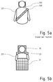
- Fig. 5a shows a seated vehicle occupant viewed from the front in a conventional vehicle.
- the upper body is restrained with a safety belt 300, which is very narrow in relation to the frontal body surface, so that the deceleration forces acting on the belt can act on a strip-shaped area of the body and cause local injuries there, even if the total deceleration due to the Accidents should be below critical limits.
- the head of the vehicle occupant 201 is not fully supported by the headrest 302 usually present, since already the projected area of the headrest 302 has a lower height than the head height. This results from the fact that the concave back of the head anyway does not lie flat and therefore rather punctual is supported.
- the neck area between the shoulder and the back of the head is rarely supported by the headrest.
- Fig. 5b shows a driver 201 from the front view in a standing room according to the invention, in turn, the support surfaces, which are provided by the collecting elements 31 and 36, are characterized by the hatched areas.
- the front and rear catch members 31, 33 are wider than the body of the rider 201 so as to be supported over the entire body width. Furthermore, a large part of the body height is supported, namely at least the area of the upper body to just below the shoulders, in order to ensure a certain freedom of movement. Further support to the leg and abdomen area may be provided by the downwardly extending front catch, which is not shown here.
- the rear side of the body is completely covered, because even there, the catch element 33 is made wider than the body of the driver 201. In the headrest 36, the width can be slightly reduced, especially to not completely obstruct the view of the rear passengers
- the collecting element 33 in the back of the driver 201 ensures a planar contact with the body and thus distributes the deceleration forces uniformly over the entire body, even if this is less critical in the back region due to the musculature which is quite strong there in the front trunk area with the organs lying there.
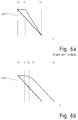
- Fig. 6a shows a schematic representation of the velocity profile of a vehicle according to the prior art over time as a solid line and a vehicle occupant as a dashed line.
- the speed of a vehicle occupant is shown by the dashed line.
- the body At the time of the accident t 0, the body has the same speed as the vehicle in which it is seated. However, it takes a time until a time t 0 , which corresponds to the so-called beltless.
- the body first moves in space with the speed imposed on it before the restraint systems take effect and the deceleration process begins.
- the period from T 0 to T 1 can be shortened by improved restraint system, such as belt tensioners, airbags, etc., which is known per se and therefore needs no further explanation here.
- Fig. 6b the deceleration deceleration of a vehicle according to the invention and a vehicle occupant traveling on a standing place therein are shown.
- the idealized assumption applies that the vehicle speed existing at the time of the accident t 0 is linearly reduced to zero at a standstill time t S.
- the deceleration of the body of the vehicle occupant is again shown by the dashed line.
- time t 1 to which the body is moved on at the original cruising speed.
- the length of time essentially depends on how close the vehicle occupant is to the catching elements.
- the loss of time between t 0 and t 1 causes the occupant load is higher than the vehicle load, but it does not depend significantly on the invention, since the further course of the delay is determined by the collecting elements and not through the vehicle compartment.
- the body In the phase between t 1 and t 2 , the body is stopped at the front layer of the collecting element. First, there is the effect of the surface conditioning of all parts of the body in order to let the pressure load act evenly on the body. Due to the low slope, the delay effect in this phase is still low.
- Fig. 6b only a main period of time between the time t 3 at which the last layer is first compressed and the stall of the body above ground at time t 4 is shown.
- the deceleration to there is approximately the same as that of the vehicle cell, but delayed in time, since the elastically or plastically deformable layers in the collecting elements virtually provide a pure personal crumple zone in which the body can move relative to the crashed vehicle, so that he just later comes to an absolute standstill as the vehicle itself.
Abstract
Ein Fahrzeug (100; 100'; 100"), mit wenigstens einem Stehplatz (21, 22, 23, 24) für einen stehenden Fahrer und/oder einen stehenden Fahrgast, besitzt einen Frontbereich (11) mit einer Stoßenergie absorbierenden Knautschzone (12). Jeder Stehplatz (21, 22, 23, 24) ist wenigstens teilweise von einer außerhalb der Knautschzone (12) angeordneten Personenrückhalteeinrichtung umgeben, welche wenigstens ein vorderes und ein hinteres Auffangelement (31, 33, 35) umfasst, das jeweils Stoß absorbierend ausgebildet ist.A vehicle (100, 100 ', 100 ") with at least one standing space (21, 22, 23, 24) for a standing driver and / or a standing passenger, has a front portion (11) with an impact energy absorbing crumple zone (12). Each standing space (21, 22, 23, 24) is at least partially surrounded by a person restraining device located outside the crumple zone (12), which comprises at least one front and one rear catch element (31, 33, 35), each of which is shock absorbing.
Description
Die Erfindung betrifft ein Fahrzeug mit wenigstens einem Stehplatz für einen stehenden Fahrer und/oder einen stehenden Fahrgast, mit einem Frontbereich, der wenigstens eine Stoßenergie absorbierende Knautschzone aufweist.The invention relates to a vehicle with at least one standing space for a stationary driver and / or a standing passenger, with a front area having at least one impact energy absorbing crumple zone.
Kraftfahrzeuge, die für den Einsatz im öffentlichen Straßenverkehr bestimmt sind, erfordern regelmäßig einen Sitzplatz für den Fahrer sowie meist auch für alle weiteren Fahrgäste. Ausnahmen sind beispielsweise im öffentlichen Personennahverkehr zugelassen, jedoch gibt auch für Kurzstreckenflüge bereits Überlegungen zur Einführung von Stehsitzen.Motor vehicles, which are intended for use on public roads, regularly require a seat for the driver and usually also for all other passengers. Exceptions are permitted, for example, in local public transport, but there are also considerations for the introduction of standing seats for short-haul flights.
Die heutzutage bei Straßenfahrzeugen verbreiteten Sicherungssysteme wie insbesondere Sicherheitsgurt und Airbag sind nur im Zusammenhang mit einer sitzenden Position der Personen wirksam, um mit einem an der Fahrzeugvorderseite und gegebenenfalls einem weiteren am Fahrzeugheck vorhandenen Verformungsbereich, der sogenannten Knautschzone, ein aufeinander abgestimmtes Sicherungssystem zu bilden. Im Falle eines Aufpralls erfolgt eine gemeinsame Verzögerung des so gesicherten Fahrers bzw. der so gesicherten Fahrgäste zusammen mit der Fahrzeugzelle. Die Knautschzonen dienen dazu, die auf die Insassen wirkenden Verzögerungskräfte zu reduzieren. Auf diese Weise kann bei modernen Fahrzeugen ein Überleben der Fahrzeuginsassen bei einem Aufprall auf ein Hindernis mit einer Relativgeschwindigkeit von etwa 50 km/h als wahrscheinlich angenommen werden.The safety systems commonly used today in road vehicles, in particular seat belts and airbags, are effective only in connection with a seated position of the persons in order to form a coordinated safety system with a deformation area at the front of the vehicle and possibly another deformation area at the rear of the vehicle, the so-called crumple zone. In the event of an impact, a common deceleration of the driver thus secured or of the passengers thus secured takes place together with the vehicle compartment. The crumple zones serve to reduce the deceleration forces acting on the occupants. In this way, in modern vehicles, a survival of the vehicle occupants in an impact on an obstacle with a relative speed of about 50 km / h is likely to be assumed.
Das Einsteigen ins Fahrzeug, das Einnehmen der Sitzposition sowie das Anlegen des Sicherheitsgurtes ist eine Prozedur, die gerade bei nur sehr kurzen Fahrtstrecken, vor allem innerorts, als sehr lästig empfunden wird. Auslieferungstätigkeiten von Zustellern, bei denen das Fahrzeug häufig bestiegen und wieder verlassen werden muss, sind wirtschaftlich kaum durchzuführen, wenn der Fahrer bei jedem Stopp des Fahrzeugs die Sitzposition einnehmen und sich abschnallen muss sowie anschließend, nach dem Einstieg, den Sicherheitsgurt wieder anlegen muss.Getting into the vehicle, taking the seat position and putting on the seatbelt is a procedure that is very annoying, especially on very short journeys, especially in urban areas. Delivery activities of deliverers, in which the vehicle frequently has to be climbed and exited, are economically difficult to carry out when the driver must take the seat position and unbuckle each time the vehicle is stopped and then, after boarding, must replace the seat belt.
Die
Auch bei anderen Nutzfahrzeugen, beispielsweise beim Einsatz von Rettungskräften oder im militärischen Bereich, ist es wünschenswert, ein schnelles Auf- und Absitzen des Fahrers und der weiteren Einsatzkräfte zu ermöglichen. Der Nachteil bei der nach
Ein Stehsitz für stehend beförderte Fahrgäste in öffentlichen Verkehrsmitteln ist aus der
Stehend bedienbare sonstige Fahrzeuge werden daher weniger im öffentlichen Straßenverkehr benutzt, sondern werden insbesondere zur Beförderung außerhalb des öffentlichen Straßenverkehrs auf Golfplätzen eingesetzt und sind beispielsweise in der
Auch bei in Betriebstätten genutzten Flurförderfahrzeugen, z. B. gemäß
Die Aufgabe der vorliegenden Erfindung besteht somit darin, bei einem Fahrzeug der eingangs genannten Art eine Fahrzeugführung durch einen stehenden Fahrer und/oder eine Beförderung von Fahrgästen im Stehen bzw. einer stehend angelehnten Haltung zu ermöglichen und dabei zugleich eine Sicherung von Fahrer und/oder Fahrgästen für den Fall eines Unfalls vorzusehen.The object of the present invention is thus to allow in a vehicle of the type mentioned a vehicle guidance by a stationary driver and / or a transport of passengers standing or a standing position leaning while at the same time a backup of the driver and / or passengers in the event of an accident.
Diese Aufgabe wird erfindungsgemäß durch ein Fahrzeug mit den Merkmalen des Anspruchs 1 gelöst.This object is achieved by a vehicle with the features of claim 1.
Dieses Fahrzeug baut in der Grundkonstruktion auf bestehenden Fahrzeugzellen auf, die im Frontbereich vor und/oder hinter den massiv ausgebildeten Teilen des Antriebsstrangs eine verformbare Zone, die sogenannte Knautschzone, aufweisen, wobei in der Regel auch für den Fall eines Heckaufpralls im Heckbereich des Fahrzeugs ein weiterer Verformungsbereich vorgesehen ist.This vehicle is based in the basic construction on existing vehicle cells, which have in front of and / or behind the solid parts of the drive train a deformable zone, the so-called crumple zone, which usually also in the event of a rear impact in the rear of the vehicle further deformation range is provided.
Das erfindungsgemäße Fahrzeug nutzt also die im Stand der Technik bereits erreichte Reduzierung der auf den menschlichen Körper einwirkenden Verzögerungskräfte durch bauliche Maßnahmen. Fahrer und Fahrgäste befinden sich bei dem erfindungsgemäßen Fahrzeug unabhängig davon, ob sie freistehend, an einen Stehsitz angelehnt oder mit einer zusätzlichen hochklappbaren Sitzfläche in halb sitzender Position fahren, immer zwischen einem vorderen und einem hinteren Auffangelement, welches nachgiebig ausgebildet ist und damit nicht nur eine mechanische Rückhaltefunktion erfüllt, sondern insbesondere stoßabsorbierend, also energieverzehrend ist.The vehicle according to the invention thus uses the already achieved in the prior art reduction of the forces acting on the human body deceleration forces by structural measures. Drivers and passengers are in the vehicle according to the invention, regardless of whether they are freestanding, leaning against a standing seat or driving with an additional foldable seat in half-sitting position, always between a front and a rear catch element, which is resilient and thus not only one fulfilled mechanical restraint function, but in particular shock-absorbing, so energy-consuming.
Erfindungsgemäß geht also die Stoßdämpfung oder Stoßabsorption über eine reine Polsterung zur Abminderung schwerster Verletzungen bei den im innerstädtischen Verkehr vorherrschenden Geschwindigkeiten deutlich hinaus. Außerdem sind die Auffangelemente frei von innenliegenden, harten Versteifungselementen, um das ungehinderte Eintauchen des Körpers in die Auffangelemente bis zur maximalen elastischen Kompression oder maximalen weichplastischen Verformung der Schicht(en) in den Auffangelementen zu ermöglichen.Thus, according to the invention, the shock absorption or impact absorption goes beyond pure upholstery to reduce the severest injuries at the speeds prevailing in inner city traffic. In addition, the trapping elements are free of internal, hard stiffening elements to the unobstructed immersion of the body in the collecting elements to the maximum allow elastic compression or maximum soft plastic deformation of the layer (s) in the collecting elements.
Die Erfindung zielt darauf ab, die Verzögerung des Körpers zwar weitgehend gleichzeitig mit der Fahrgastzelle zu initiieren, diese aber soweit wie möglich von der Fahrgastzelle zu entkoppeln. Der Körper kann nach der Erfindung von der sonstigen Fahrzeugzelle und dem Chassis teilweise unabhängig allein innerhalb der nachgiebigen Auffangelemente gebremst werden, indem seine kinetische Energie durch elastische und/oder plastische Verformung absorbiert wird. Die einzige Verbindung des Körpers zur Fahrgastzelle besteht indirekt, da die Auffangelemente, auf die er aufprallt, als solche mit der Fahrgastzelle verbunden sind. Die Verbindung erfolgt selbstverständlich nur in den Bereichen, die nicht die Anprallseite darstellen.The invention aims to initiate the deceleration of the body largely simultaneously with the passenger compartment, but to decouple it as far as possible from the passenger compartment. The body can be braked according to the invention of the other vehicle compartment and the chassis partially independently alone within the resilient collecting elements by its kinetic energy is absorbed by elastic and / or plastic deformation. The only connection of the body to the passenger compartment is indirect, since the collecting elements on which it bounces are connected as such to the passenger compartment. The connection is of course only in the areas that do not represent the impact side.
Anders als bei den bekannten Rückhaltesystemen, die den Körper an die Fahrgastzelle koppeln und den Körper damit zwangsläufig mit derselben Verzögerung bzw. negativen Beschleunigung belasten wie die Fahrgastzelle, wenn nicht sogar stärker, kann nach der Erfindung der Verzögerungsweg und damit die Verzögerungszeit ausgedehnt werden. Entsprechend sinkt die auf den Körper wirkende Beschleunigung. Anschaulich gesprochen kann sich bei dem Fahrzeug nach der Erfindung der Körper noch innerhalb der nachgiebigen Schaumschichten oder sonstigen Schichten, die die Auffangelemente bilden, weiterbewegen, wenn die Fahrgastzelle bereits zum Stillstand gekommen ist.Unlike the known restraint systems which couple the body to the passenger compartment and thereby forcibly load the body with the same deceleration or negative acceleration as the passenger compartment, if not more, according to the invention the deceleration path and hence the deceleration time can be extended. Accordingly, the acceleration acting on the body decreases. Illustratively speaking, in the vehicle according to the invention, the body can still move within the resilient foam layers or other layers which form the catching elements when the passenger compartment has already come to a standstill.
Außerdem bilden die Auffangelemente eine sehr breite Auffangfläche, die vorzugsweise sogar breiter ist als die Anprallfläche des Körpers des Fahrers oder Passagiers ist, so dass im Falle eines Aufpralls der Körper des Insassen vollflächig gegen die Auffangfläche geschleudert wird und im weiteren Verlauf des Unfalls dann gegen die rückwärtige Auffangfläche zurückgeschleudert wird. Eine punktuelle Überbelastung einzelner Körperregionen wird durch die großflächige Verteilung vermieden. Die Auffangflächen erstrecken sich dabei bis über den Körperschwerpunkt hinaus nach oben und enden vorzugsweise so weit unterhalb der Schultergelenke, dass zumindest der Fahrer und ggf. auch die Insassen die Arme bequem auf der Oberseite der Auffangelemente oder an sonstigen geeigneten Auflageflächen ablegen können. Der Körperschwerpunkt ist auf Höhe des Oberbauches anzunehmen, so dass sich die Auffangelemente entsprechend zumindest bis auf Brusthöhe erstrecken sollte.In addition, the collecting elements form a very wide collecting surface, which is preferably even wider than the impact surface of the body of the driver or passenger, so that in the event of an impact, the body of the occupant is hurled over the entire surface against the collecting surface and then in the course of the accident against the back catch area is thrown back. A point overloading of individual body regions is avoided by the large-area distribution. The collecting surfaces extend upwards beyond the center of gravity of the body and preferably end below the shoulder joints so far that at least the driver and possibly also the occupants can place the arms comfortably on the upper side of the collecting elements or on other suitable supporting surfaces. The body center of gravity is assumed to be at the level of the upper abdomen, so that the collecting elements should extend at least up to the level of the breast.
Das Lenkrad, oder ein bügelförmiger Lenker wie er bei Zweirädern und Quads üblich ist, ist nach der Erfindung mit den weiteren notwendigen Bedienelementen von oberhalb des vorderen Auffangelements frei zugänglich. Ein Kontakt des Oberkörpers des Fahrers mit dem Lenkrad und anderen Bedienelementen bei einem Unfall wird somit auch dann vermieden, wenn der Fahrer an die vordere Auffangfläche geschleudert wird und es zu einer starken Verformung des dortigen Auffangelements kommt.The steering wheel, or a bow-shaped handlebar as is common in two-wheelers and quads, is freely accessible according to the invention with the other necessary controls from above the front collecting element. A contact of the driver's upper body with the steering wheel and other controls in an accident is thus avoided even when the driver is thrown to the front collecting surface and there is a strong deformation of the local collecting element.
Vorzugsweise ist die Rückhaltevorrichtung so ausgebildet, dass sie den Oberkörper der Insassen nicht nur in projizierter Fläche vorwärts und rückwärts zur Fahrtrichtung, sondern vollumfänglich umschließt. Das vordere und das hintere Auffangelement als nach der Erfindung vorgesehene Mindestausstattung sind dazu um ein in der Fahrzeugmitte angeordnetes Mittelteil ergänzt und zu einer von oben gesehen hufeisenförmigen Struktur erweitert. Die verbleibende seitliche Lücke in diesem Ring dient dem leichten Ein- und Aussteigen von der Fahrzeugseite her.Preferably, the restraint device is designed so that it encloses the upper body of the occupant not only in projected area forward and backward to the direction of travel, but in full. The front and the rear collecting element as provided according to the invention minimum equipment are supplemented to a arranged in the middle of the vehicle middle part and expanded to a horseshoe-shaped structure seen from above. The remaining lateral gap in this ring is used for easy entry and exit from the vehicle side.
Erfindungsgemäß wird also ein sehr sicheres Fahrzeug bereitgestellt, das zudem ein schnelles Zu- und Aussteigen von allen Insassen ermöglicht und sich damit insbesondere für Lieferdienste, Postzustellung sowie für militärische Einsatzszenarien eignet, also für solche Anwendungsfelder, in denen ein häufiges, schnelles Zusteigen und Verlassen möglich sein soll.According to the invention, therefore, a very secure vehicle is provided, which also allows fast entry and exit of all occupants and is thus particularly suitable for delivery services, postal delivery and military deployment scenarios, ie for those applications in which a frequent, fast boarding and leaving possible should be.
Die auf der Einstiegsseite noch verbleibende Öffnung wird vorzugsweise durch ein Zusatz-Auffangelement geschlossen, welches an der Innenseite einer Fahrzeugtür befestigt ist. Mit dem Schließen der Fahrzeugtür wird somit ein Ring komplett um den Fahrer bzw. die anderen Insassen herum gelegt, sodass auch ein Schutz für den Fall eines Seitenaufpralls gegeben ist. Auch für diesen Unfalltyp ergibt sich eine gute Schutzwirkung, weil die hochgezogene Rückhaltevorrichtung frühzeitig den Körper im Schwerpunkt aufhält und daher keine seitlichen Überstreckungen der Wirbelsäule möglich sind. Auch bei einem rundum angeordneten Auffangelement kann ein bequemes Aus- und Zusteigen ermöglicht werden, weil die Ausstiegsöffnung automatisch beim Schließen der Tür mit gesichert wird. Außer der erhöhten Bequemlichkeit für den innerörtlichen Kurzstreckenverkehr ist auch ein wirtschaftlicher Vorteil durch das erfindungsgemäße Fahrzeug gegeben, da die Kosten für Installation und Wartung sowie spätere Entsorgung der hoch entwickelten Sicherungssysteme einschließlich Sensoren und Pyrotechnik entfallen können. Der Sicherheitsgurt selbst kann ebenso entfallen wie die damit im Zusammenhang stehenden Zusatzsysteme wie Gurtstraffer und Gurtkraftbegrenzer. Auch die frontal angeordneten Airbags einschließlich der zugehörigen Sensorik werden zumindest außerhalb des Fahrerplatzes nicht mehr benötigt. Durch den Entfall der Airbags wird auch die Gefahr für Unfallhelfer gemindert, die durch verzögert ausgelöste Airbags erheblich verletzt werden können. Statt den Körper an einer relativ schmalen Fläche zurückzuhalten, wie beim Sicherheitsgurt, wird nach der Erfindung eine über die Körperfläche gleichmäßig verteilte Belastung erreicht. Belastungsspitzen während des Unfallgeschehens werden reduziert, so dass die maximal zulässigen biomechanischen Belastungswerte bei einem normierten, auf den innerstädtischen Verkehr bezogenen Unfallgeschehen unterschritten werden.The remaining on the entry side opening is preferably closed by an additional catch element which is fixed to the inside of a vehicle door. With the closing of the vehicle door thus a ring is placed completely around the driver or the other occupants around, so that a protection is provided in the event of a side impact. Also for this type of accident results in a good protective effect, because the raised retainer early stop the body in the center of gravity and therefore no lateral hyperextension of the spine are possible. Even with a completely arranged collecting element a comfortable extension and retraction can be made possible because the exit opening is automatically secured when closing the door with. In addition to the increased convenience for the local short-distance traffic also an economic advantage is given by the vehicle according to the invention, since the cost of installation and maintenance and subsequent disposal of sophisticated security systems including sensors and pyrotechnics can be omitted. The safety belt itself can be omitted as well as the associated additional systems such as belt tensioners and belt force limiters. Even the frontally arranged airbags including the associated sensors are no longer needed at least outside the driver's seat. The elimination of the airbags also reduces the risk for accident workers, which can be significantly injured by delayed triggered airbags. Instead of restraining the body on a relatively narrow surface, such as the seatbelt, according to the invention a load uniformly distributed over the body surface is achieved. Peak loads during the accident are reduced, so that the maximum permissible biomechanical load values are undercut in a normalized, related to the inner city traffic accidents.
Ein zusätzliches Rückhalteelement kann vorgesehen sein, um die Insassen für den Fall eines Fahrzeugüberschlags zusätzlich zu schützen, indem sie in dem rundum gesicherten Stehplatz auch gegenüber vertikal wirkenden Kräften festgehalten werden. Dies kann durch ein einfaches Beckengurtsystem bewirkt werden oder insbesondere durch eine nicht-lineare vertikale Erstreckung der Auffangelemente, so dass die Person auch in vertikaler Richtung zurückgehalten wird.An additional retaining element may be provided to additionally protect the occupants in the event of a vehicle rollover by being held in the all-round secure standing even against vertically acting forces. This can be effected by a simple lap belt system, or in particular by a non-linear vertical extension of the catch elements, so that the person is also retained in the vertical direction.
Eine bevorzugte Ausführungsform sieht einen kurzen, wenig vorspringenden Stehsitz vor, der sich vor der hinteren Auffangfläche befindet und der höhenverstellbar angeordnet ist. Zusätzlich ist vorzugsweise ein in der Höhe veränderbares Bodenpodest vorgesehen. Mit diesen Maßnahmen kann erreicht werden, dass die Armhöhe des Fahrers konstant ist, sodass dieser die oberhalb des vorderen Auffangelements befindlichen Lenk- und Bedienelemente unabhängig von seiner eigenen Körpergröße bequem erreichen und bedienen kann. Dazu ist die Höhe des vorderen Auffangelements vorzugsweise auf einen sogenannten Norm-Menschen mit einer Durchschnittshöhe von 1,75 m abgestimmt. Wesentlich größere Fahrer mit einer Größe von 1,90 m und mehr können den Stehsitz absenken, um in einer leicht abgestützten, mit den Beinen schräg nach unten verlaufenden Haltung die eigene Schulterhöhe abzusenken. Kleine Personen mit einer Größe von etwa 1,60 m hingegen können durch Verstellung des Bodenpodestes und des Stehsitzes in eine erhöhte Position gebracht werden, so dass die Schulterhöhe angehoben wird.A preferred embodiment provides a short, slightly protruding standing seat, which is located in front of the rear collecting surface and is arranged vertically adjustable. In addition, a height adjustable floor pedestal is preferably provided. With these measures can be achieved that the arm height of the driver is constant, so that it can easily reach and operate the located above the front collecting element steering and controls regardless of his own height. For this purpose, the height of the front collecting element is preferably matched to a so-called standard man with an average height of 1.75 m. Much larger riders of 1.90m or more can lower the standing seat to lower their own shoulder height in a slightly propped, slanting downhill posture. By contrast, small persons with a height of about 1.60 m can be brought into an elevated position by adjusting the floor pedestal and the standing seat so that the shoulder height is raised.
Eine weitere bevorzugte Ausführungsform sieht vor, die Auffangelemente so verstellbar zu machen, dass der Abstand zum Körper des Fahrers in Bezug auf die Fahrzeuglängsachse, ggf. auch in Bezug auf die Fahrzeugquerachse, leicht variiert werden kann. Der Abstand wird vorzugsweise so gewählt, dass er nur etwas größer ist als die sogenannte Gurtlose bei herkömmlichen Fahrzeugen, also als der Weg, der im Falle eines Unfalls ohne Rückhaltwirkung des Sicherheitsgurtes zurückgelegt wird, bis dieser gespannt am Körper des Insassen anliegt und diesen zurückhält.A further preferred embodiment provides to make the collecting elements so adjustable that the distance to the body of the driver with respect to the Vehicle longitudinal axis, possibly also in relation to the vehicle transverse axis, can be easily varied. The distance is preferably chosen so that it is only slightly larger than the so-called belt slack in conventional vehicles, so as the way that is covered in the event of an accident without retention effect of the seat belt until it rests taut on the body of the occupant and holds it back.
Vorgesehen sein kann noch, dass die Auffangelemente zonenweise unterteilt sind und die Zonen aus unterschiedlich nachgiebigen Werkstoffen gebildet sind. Die näher zu der Person angeordneten Schichten sollten dabei weicher sein als die dahinter liegenden. Der anprallende Körper wird somit zunächst weich aufgefangen und es wird aufgrund der Nachgiebigkeit der äußeren Schicht eine gute Druckverteilung erreicht, so dass eine vollflächige Belastung der gesamten Körperfläche erfolgt und nicht nur eine punktuelle Abstützung an einzelnen, exponierten Flächenbereichen.It can also be provided that the collecting elements are subdivided in zones and the zones are formed of materials of different yielding properties. The layers closer to the person should be softer than those behind them. The impacting body is thus initially collected soft and it is achieved due to the flexibility of the outer layer, a good pressure distribution, so that a full-surface load on the entire body surface is done and not only a punctual support to individual, exposed surface areas.
Eine Abstufung der Härte der Auffangelemente kann auch in der Höhe erfolgen, da aufgrund der geringeren Masse des Unterkörpers der Impuls beim Anprall dort weniger stark ist. Hierdurch ist es auch möglich, den unteren Bereich eines Auffangelements rückspringend auszuführen, indem durch eine größere Härte des Werkstoffes ein geringerer Verformungsweg vorgesehen wird und der eingesparte Verformungsweg zur Vergrößerung des Fußraums und damit zur Bequemlichkeit des stehenden Fahrers oder Fahrgastes genutzt wird. Im Fußraum können auch Tast- oder Pedalelemente angeordnet sein, um das Fahrzeug in Gang zu setzen und zu bremsen.A gradation of the hardness of the collecting elements can also be carried out in height, since due to the lower mass of the lower body of the momentum during impact there is less strong. This also makes it possible to perform the lower portion of a collecting element rebounding by a lower deformation path is provided by a greater hardness of the material and the saved deformation is used to increase the footwell and thus for the convenience of the stationary driver or passenger. In the footwell also tactile or pedal elements may be arranged to set the vehicle in motion and to brake.
Vorzugsweise ist die Abstufung der Werkstoffhärte in Fahrzeuglängsrichtung mit dem Verlauf der Knautschzonen harmonisiert, sodass die im zeitlichen Verlauf des Unfallgeschehens auftretenden Belastungen in Form von unterschiedlich starken Verzögerungen vergleichmäßigt werden und Spitzenwerte der Belastung auf ein für den menschlichen Körper erträgliches Maß reduziert werden.Preferably, the gradation of the material hardness in the vehicle longitudinal direction is harmonized with the course of the crumple zones, so that the loads occurring in the course of the accident are made uniform in the form of delays of varying degrees and peak values of the load are reduced to an extent tolerable for the human body.
Weiterhin vorzugsweise ist die Nachgiebigkeit der Auffangelemente so ausgelegt, dass zunächst eine vollflächige Anlage des Körpers erreicht wird und dann bei dem zu erwartenden Unfalllgeschehen der Verzögerungsweg über den durch die jeweils betroffene Knautschzone ermöglichten Verformungsweg hinausgeht. Die Verzögerungszeit, also die Zeitspanne zwischen Unfalleintritt und Stillstand des Körpers des Fahrzeuginsassen gegenüber dem Grund wird verlängert. Entsprechend sinkt die Beschleunigung als Ableitung der Geschwindigkeit nach der Zeit und folglich die damit einhergehenden Rückhaltekräfte, die auf den Körper wirken.Further preferably, the flexibility of the collecting elements is designed so that first a full-surface conditioning of the body is achieved and then in the expected accident events the delay path beyond the allowed by the respective crumple deformation zone. The delay time, ie the time interval between accident entry and standstill of the body of the vehicle occupant relative to the ground is extended. Accordingly, the sinks Acceleration as a derivative of speed over time and, consequently, the associated restraining forces acting on the body.
Die Erfindung wird nachfolgend mit Bezug auf die in den Zeichnungen dargestellten Ausführungsbeispiele näher erläutert. Die Figuren zeigen im Einzelnen:
- Fig. 1
- ein Fahrzeug mit vier Stehplätzen in einem schematischen Grundriss;
- Fig. 2
- ein Fahrzeug mit zwei Stehplätzen in einem schematischen Grundriss;
- Fig. 3a, 3b
- das Fahrzeug gemäß
Fig. 1 gemäß einer ersten Ausführungsform in seitlicher Ansicht; und - Fig. 4
- das Fahrzeug gemäß
Fig. 1 gemäß einer zweiten Ausführungsform in seitlicher Ansicht; - Fig. 5a
- eine schematische Ansicht auf einen Oberkörper eines sitzenden Fahrers mit Sicherheitsgurt nach dem Stand der Technik;
- Fig. 5b
- eine schematische Ansicht auf einen Oberkörper eines stehenden Fahrers in einem Stehplatz nach der Erfindung;
- Fig. 6a
- ein vereinfachtes Zeit-Geschwindigkeitsdiagramm für einen Unfallablauf an einem herkömmlichen Fahrzeug und
- Fig. 6b
- ein vereinfachtes Zeit-Geschwindigkeitsdiagramm für einen Unfallablauf an einem erfindungsgemäßen Fahrzeug.
- Fig. 1
- a vehicle with four standing places in a schematic plan view;
- Fig. 2
- a vehicle with two standing places in a schematic plan view;
- Fig. 3a, 3b
- the vehicle according to
Fig. 1 according to a first embodiment in side view; and - Fig. 4
- the vehicle according to
Fig. 1 according to a second embodiment in a side view; - Fig. 5a
- a schematic view of an upper body of a seated driver with safety belt according to the prior art;
- Fig. 5b
- a schematic view of an upper body of a standing driver in a standing room according to the invention;
- Fig. 6a
- a simplified time-velocity diagram for an accident sequence on a conventional vehicle and
- Fig. 6b
- a simplified time-velocity diagram for an accident process on a vehicle according to the invention.
In
Die gestrichelten Linien kennzeichnen in
In dem Fahrzeug 100 sind vier Stehplätze 21, 22, 23, 24 ausgebildet. Der Stehplatz 21 ist für den Fahrer vorgesehen und der Stehplatz 22 für den Beifahrer. Im Fond sind zwei weitere Stehplätze 23, 24 für weitere Fahrgäste vorgesehen.In the
Vor den Stehplätzen 21, 22 befindet sich ein vorderes Auffangelement 33. Oben darauf aufliegend ist ein Lenkerbügel oder ein Lenkrad 17 angeordnet. Hinter den vorderen Stehplätzen 21, 22 befindet sich ein Auffangelement 33, das als hinteres Auffangelement für die Personen auf den vorderen Stehplätzen 21, 22 dient und zugleich ein vorderes Auffangelement für die Fahrgäste auf den hinteren Stehplätzen 23, 24 bildet. Hinter der zweiten Reihe ist ein hinteres Auffangelement 35 angeordnet.In front of the
Zur seitlichen Abstützung dienen zunächst Trennelemente 37, 39, die jeweils zwischen den in einer Reihe nebeneinanderstehenden Fahrgästen angeordnet sind. An den Innenseiten aller vier Fahrzeugtüren 15 sind zudem Zusatz-Auffangelemente 32 angeordnet, so dass sich bei geschlossenen Fahrzeugtüren 15 auf jedem der Stehplätze 21,...,24 ein vollständiger Ring aus Auffangelementen 31...37 um den Fahrer und die Fahrgäste legt.For lateral support serve dividing
An jedem Stehplatz 21,...,24 ist zudem jeweils eine Kopfstütze 36 vorgesehen, die über die sonstigen Auffangelemente 31, 32, 33, 35, 37, 39 hinweg nach oben ragt. Ein kleiner Stehsitz 34 an jedem Stehplatz 21, 22, 23, 24 ermöglicht den Personen, eine bequeme, angelehnte Haltung einzunehmen.At each
In
An einem Stehplatz 21 steht der Fahrer 201 auf dem Fahrzeugboden und lehnt sich an das hinter ihm liegende Auffangelement 33 an, wobei das Gesäß an einem kleinen Stehsitz 34 abgestützt werden kann. Der Fahrer 201 kann so eine entspannte, stehend-angelehnte Haltung einnehmen und muss auch nicht viel Kraft aufzuwenden, um sich gegen die im normalen Fahrbetrieb auftretenden Beschleunigungen und Verzögerungen abzustützen. Das vordere Auffangelement 31, das hintere Auffangelement 33 und auch der Stehsitz 34 sind aus weichen, nachgiebigen Werkstoffen gebildet, wie beispielsweise offenzelligen Schaumstoffen, die sich zumindest oberflächlich elastisch verformen, und/oder bestehen aus hochviskosen Formmassen oder aus kollabierenden Strukturen, bei denen beim Anprall des Körpers des Fahrers 201 eine plastische Verformung eintritt.At a
Erkennbar ist in
Am hinteren Stehplatz 23 beschreibt das Auffangelement an der einem Fahrgast 202 zugewandten Rückseite eine ähnliche Kontur. Ein höhenverstellbarer Stehsitz ist hier nicht erforderlich; der Stehsitz ist direkt an das hintere Auffangelement 35 angeformt.At the
Sind die Türen geöffnet, bestehen die in
In
Den Darstellungen in
Bei den Fahrgästen 202 prallt der Kopf während des Unfalls möglicherweise gegen das vordere Auffangelement 33, das aber nachgiebig ausgebildet ist. Nur beim Stehplatz 21 für den Fahrer kann das Auffangelement 31 nicht ganz so weit hoch gezogen werden, um eine gute Sicht und eine bequeme Bedienung des Lenkrads 17 zu ermöglichen. Hier kann ein zusätzlicher Lenkradairbag sinnvoll sein oder ein Lenkerbügel verwendet werden, der außerhalb der Reichweite des Kopfes angeordnet ist.In the case of the
Das Auffangelement 31" am Stehplatz 21 für den Fahrer 201 ist sowohl in Fahrzeuglängsrichtung wie auch in Bezug auf die Hochachse in unterschiedliche Schichten unterteilt, die unterschiedlich nachgiebig ausgebildet sind. Ein Anprallbereich 31.2", der bei einem Unfall als erstes Körperkontakt bekommt, ist im Vergleich zu einer vorderen Schicht 31.1" weich ausgebildet, um sich möglichst schnell und möglichst vollflächig an den Körper anzulehnen. Dadurch wird der Körper gleichmäßig mit seiner gesamten frontalen Fläche belastet und der von dem Körper ausgehende Impuls verteilt sich auf eine maximale Fläche, bevor er auf die etwas härtere vordere Schicht 31.1" trifft, an der er weiter verzögert wird.The catching
In der zweiten Unfallphase wird der Körper zurückgeschleudert und von den hinter ihm angeordneten Auffangelementen 33", 35" aufgefangen. Der Fahrer 201 prallt dabei gegen die Schicht 33.1" und der Fahrgast 202 gegen das hintere Auffangelement 35".In the second accident phase, the body is thrown back and caught by the
Eine dritte Schicht 31.3", 33.3" besteht bei beiden Auffangelementen 31 ", 33" jeweils im Bereich des Fußraums. Der von den unteren Extremitäten ausgehende Impuls ist aufgrund der geringeren Masse kleiner als im Rumpfbereich. Dadurch kann die den Beinen und Füßen zugeordnete untere Schicht 31.3" in Fahrzeuglängsrichtung dünner ausgebildet sein als oben und/oder die Schicht 31.3" kann weicher ausgebildet sein.A third layer 31.3 ", 33.3" in both collecting
Auch hierbei ist vorteilhaft, dass das Auffangelement 33 im Rücken des Fahrers 201 für eine flächige Anlage an den Körper sorgt und die Verzögerungskräfte damit gleichmäßig auf den gesamten Körper verteilt, auch wenn dies im Rückenbereich auf Grund der dort recht starken Muskulatur weniger kritisch ist, als im vorderen Rumpfbereich mit den dort liegenden Organen.Here, too, it is advantageous that the collecting
Zu einem Unfallzeitpunkt t0 findet der Zusammenstoß mit dem Hindernis statt und es beginnt unmittelbar die Verzögerung des Fahrzeugs bis zum Stillstand zum Zeitpunkt tS. Zur Vereinfachung ist hier die Abnahme der Fahrzeuggeschwindigkeit v(t) als gerade Linie dargestellt, auch wenn sich in einem realen Unfallgeschehen unterschiedliche Teilabläufe ergeben, je nachdem welche Bereiche des Fahrzeugs gerade verformt werden. Die Steigung dieser idealisierten Linie entspricht der Verzögerung, die auf das Fahrzeug wirkt.At an accident time t 0 the collision with the obstacle takes place and immediately the deceleration of the vehicle begins until standstill at time t S. For simplification, the decrease of the vehicle speed v (t) is shown here as a straight line, even if different partial sequences result in a real accident, depending on which areas of the vehicle are being deformed. The slope of this idealized line corresponds to the deceleration that acts on the vehicle.
Die Geschwindigkeit eines Fahrzeuginsassen ist mit der gestrichelten Linie dargestellt. Der Körper weist zum Unfallzeitpunkt t0 dieselbe Geschwindigkeit auf wie das Fahrzeug, in dem er sitzt. Es vergeht jedoch eine Zeitspanne bis zu einem Zeitpunkt t0, die der sogenannten Gurtlosen entspricht. Der Körper bewegt sich zunächst mit der ihm aufgeprägten Geschwindigkeit im Raum weiterbewegt, bevor die Rückhaltesysteme greifen und der Verzögerungsvorgang beginnt. Die Zeitspanne von T 0 bis T 1 kann durch verbesserte Rückhaltesystem, wie Gurtstraffer, Airbag usw. verkürzt werden, was an sich bekannt ist und daher hier keiner näheren Erläuterung bedarf. Wesentlich ist aber, dass in einem herkömmlichen Fahrzeug, bei dem die Fahrzeuginsassen über Rückhaltesysteme mit der Fahrzeugzelle verbunden sind, bei Stillstand des Fahrzeugs zum Zeitpunkt tS auch der Körper der Fahrzeuginsassen zum Stillstand gekommen sein muss. Da der Verzögerungsvorgang aber später einsetzt, ergibt sich eine deutlich höhere Steigung der Linie zwischen den Punkten t1 und tS, mithin eine stärkere Verzögerung und somit deutlich erhöhte Kräfte.The speed of a vehicle occupant is shown by the dashed line. At the time of the accident t 0, the body has the same speed as the vehicle in which it is seated. However, it takes a time until a time t 0 , which corresponds to the so-called beltless. The body first moves in space with the speed imposed on it before the restraint systems take effect and the deceleration process begins. The period from T 0 to T 1 can be shortened by improved restraint system, such as belt tensioners, airbags, etc., which is known per se and therefore needs no further explanation here. It is essential, however, that in a conventional vehicle in which the vehicle occupants are connected via restraint systems with the vehicle compartment, at standstill of the vehicle at time t S and the body of the vehicle occupants must come to a standstill. However, since the deceleration process starts later, there is a significantly higher slope of the line between the points t 1 and t S , thus a stronger deceleration and thus significantly increased forces.
In
Auch bei dem erfindungsgemäßen Fahrzeug ergibt sich ein Zeitpunkt t1, bis zu dem der Körper mit der ursprünglichen Reisegeschwindigkeit weiterbewegt wird. Die Zeitspanne hängt im Wesentlichen davon ab, wie nah der Fahrzeuginsasse zu den Auffangelementen positioniert ist. Anders als im Stand der Technik, wo der Zeitverlust zwischen t0 und t1 dazu führt, dass die Insassenbelastung höher ist als die Fahrzeugbelastung, kommt es erfindungsgemäß aber nicht wesentlich hierauf an, da der weitere Verlauf der Verzögerung durch die Auffangelemente bestimmt wird und nicht durch die Fahrzeugzelle.Also in the vehicle according to the invention there is a time t 1 , to which the body is moved on at the original cruising speed. The length of time essentially depends on how close the vehicle occupant is to the catching elements. Unlike in the prior art, where the loss of time between t 0 and t 1 causes the occupant load is higher than the vehicle load, but it does not depend significantly on the invention, since the further course of the delay is determined by the collecting elements and not through the vehicle compartment.
In der Phase zwischen t1 und t2 wird der Körper an der vorderen Schicht des Auffangelements aufgehalten. Es ergibt sich zunächst der Effekt der flächigen Anlage aller Körperteile, um die Druckbelastung gleichmäßig auf den Körper wirken zu lassen. Entsprechend der geringen Steigung ist die Verzögerungswirkung in dieser Phase noch gering.In the phase between t 1 and t 2 , the body is stopped at the front layer of the collecting element. First, there is the effect of the surface conditioning of all parts of the body in order to let the pressure load act evenly on the body. Due to the low slope, the delay effect in this phase is still low.
Beispielhaft ist eine weitere Phase von t2 nach t3 dargestellt, bei der eine weitere Schicht komprimiert wird, die etwas steifer ausgelegt ist und damit zu einer stärkeren Verzögerung führt.By way of example, another phase from t 2 to t 3 is shown, in which a further layer is compressed, which is made somewhat stiffer and thus leads to a greater delay.
Durch diese Abstufung wird der Übergang in der Verzögerung von dem sehr abrupten Verlauf, wie er im Stand der Technik gemäß
Zur Erläuterung der Erfindung ist in
In dem also ermöglicht wird, den Körper der Fahrzeuginsassen über einen längeren Zeitraum zu verzögern als im Stand der Technik möglich, weil die Bindung an die Fahrzeugzelle aufgehoben wird, können niedrigere negative Beschleunigungen und damit niedrigere Kräfte erreicht werden. Die niedrigeren Kräfte werden zudem auf eine größere Fläche des Körpers verteilt, so dass die Druckbelastung von Körperpartien gegenüber herkömmlichen Fahrzeugen deutlich reduziert ist.Thus, by making it possible to decelerate the body of the vehicle occupants over a longer period of time than is possible in the prior art because the binding to the vehicle compartment is canceled, lower negative accelerations and thus lower forces can be achieved. The lower forces are also distributed over a larger area of the body, so that the pressure load of body parts compared to conventional vehicles is significantly reduced.
Claims (10)
dadurch gekennzeichnet, dass jeder Stehplatz (21, 22, 23, 24) in Fahrtrichtung gesehen jenseits der Knautschzone (12) angeordnet ist und wenigstens teilweise von einer außerhalb der Knautschzone (11) angeordneten Personenrückhalteeinrichtung umgeben ist, welche wenigstens je ein vorderes und ein hinteres Auffangelement (31, 33, 35) umfasst, das jeweils stoßabsorbierend ausgebildet ist und das sich vom Fußbereich bis über einen Körperschwerpunkt des Fahrers (201) oder Fahrgastes (202) hinaus nach oben erstreckt.Vehicle (100, 100 ', 100 "), having at least one standing space (21, 22, 23, 24) for a standing driver (201, 201') and / or a standing passenger (20), having a front area (11). comprising at least one impact energy absorbing crumple zone (12),
characterized in that each standing space (21, 22, 23, 24) viewed in the direction of travel beyond the crumple zone (12) is arranged and at least partially surrounded by a outside the crumple zone (11) arranged person restraint, which at least one front and one rear Collecting element (31, 33, 35), each of which is shock-absorbing and extending from the foot to a body center of gravity of the driver (201) or passenger (202) also extends upward.
Applications Claiming Priority (1)
| Application Number | Priority Date | Filing Date | Title |
|---|---|---|---|
| DE102015115200.2A DE102015115200B4 (en) | 2015-09-09 | 2015-09-09 | Vehicle with at least one standing place for a standing driver and/or a standing passenger |
Publications (2)
| Publication Number | Publication Date |
|---|---|
| EP3141436A1 true EP3141436A1 (en) | 2017-03-15 |
| EP3141436B1 EP3141436B1 (en) | 2019-05-08 |
Family
ID=56893850
Family Applications (1)
| Application Number | Title | Priority Date | Filing Date |
|---|---|---|---|
| EP16188034.9A Active EP3141436B1 (en) | 2015-09-09 | 2016-09-09 | Vehicle having at least one standing place for a standing driver and/or a standing passenger |
Country Status (2)
| Country | Link |
|---|---|
| EP (1) | EP3141436B1 (en) |
| DE (1) | DE102015115200B4 (en) |
Cited By (4)
| Publication number | Priority date | Publication date | Assignee | Title |
|---|---|---|---|---|
| CN108802350A (en) * | 2018-09-04 | 2018-11-13 | 山东交通学院 | A kind of H-shaped guide rail for the circulating accelerating and loading test equipment of straight line |
| JP2020050071A (en) * | 2018-09-26 | 2020-04-02 | トヨタ自動車株式会社 | Occupant protection structure of vehicle |
| WO2021069380A1 (en) * | 2019-10-10 | 2021-04-15 | Zf Friedrichshafen Ag | Passenger protection for a motor vehicle |
| CN114379435A (en) * | 2022-02-14 | 2022-04-22 | 伍洪少 | Bus and truck capable of being driven in standing mode |
Citations (12)
| Publication number | Priority date | Publication date | Assignee | Title |
|---|---|---|---|---|
| DE836748C (en) * | 1950-10-27 | 1952-04-17 | Franz Derwahl | Safety arrangement for occupants in vehicles, especially in passenger vehicles |
| US3603535A (en) * | 1968-11-13 | 1971-09-07 | Maurice Depolo | Lifesaving support system |
| JPS62101586A (en) | 1985-10-30 | 1987-05-12 | Yamaha Motor Co Ltd | Four-wheel golf cart for carrying standing person |
| DE19518116A1 (en) * | 1994-05-20 | 1995-11-23 | Linde Ag | Industrial truck with a driver's cab |
| DE19544266A1 (en) * | 1994-12-23 | 1996-06-27 | Ford Werke Ag | Energy absorbing vehicle door |
| EP0568775B1 (en) | 1992-05-04 | 1998-04-01 | Jungheinrich Aktiengesellschaft | Supporting platform for a driver standing upright on a lifting truck |
| DE19814548C1 (en) | 1998-04-01 | 1999-07-22 | Schimmelpfennig Karl Heinz | Seat for passenger vehicle |
| WO2000038959A1 (en) * | 1998-12-30 | 2000-07-06 | Automotive Systems Laboratory, Inc. | Occupant detection system |
| EP1127788A1 (en) * | 2000-02-23 | 2001-08-29 | EADS Airbus GmbH | Aircraft cabin passenger layout |
| WO2006032275A2 (en) | 2004-09-24 | 2006-03-30 | Lorens Peter Iversen | Transporting device |
| CA2696407A1 (en) | 2009-05-06 | 2010-11-06 | Sears Manufacturing Company | Vehicle seat apparatus |
| DE102013214779A1 (en) * | 2013-07-29 | 2015-01-29 | Siemens Aktiengesellschaft | Ergonomically flexible driver's cab of a rail vehicle |
Family Cites Families (1)
| Publication number | Priority date | Publication date | Assignee | Title |
|---|---|---|---|---|
| IT979462B (en) | 1972-03-03 | 1974-09-30 | Espenso L | TERMINAL FOR ELECTRICAL CONNECTIONS |
-
2015
- 2015-09-09 DE DE102015115200.2A patent/DE102015115200B4/en active Active
-
2016
- 2016-09-09 EP EP16188034.9A patent/EP3141436B1/en active Active
Patent Citations (12)
| Publication number | Priority date | Publication date | Assignee | Title |
|---|---|---|---|---|
| DE836748C (en) * | 1950-10-27 | 1952-04-17 | Franz Derwahl | Safety arrangement for occupants in vehicles, especially in passenger vehicles |
| US3603535A (en) * | 1968-11-13 | 1971-09-07 | Maurice Depolo | Lifesaving support system |
| JPS62101586A (en) | 1985-10-30 | 1987-05-12 | Yamaha Motor Co Ltd | Four-wheel golf cart for carrying standing person |
| EP0568775B1 (en) | 1992-05-04 | 1998-04-01 | Jungheinrich Aktiengesellschaft | Supporting platform for a driver standing upright on a lifting truck |
| DE19518116A1 (en) * | 1994-05-20 | 1995-11-23 | Linde Ag | Industrial truck with a driver's cab |
| DE19544266A1 (en) * | 1994-12-23 | 1996-06-27 | Ford Werke Ag | Energy absorbing vehicle door |
| DE19814548C1 (en) | 1998-04-01 | 1999-07-22 | Schimmelpfennig Karl Heinz | Seat for passenger vehicle |
| WO2000038959A1 (en) * | 1998-12-30 | 2000-07-06 | Automotive Systems Laboratory, Inc. | Occupant detection system |
| EP1127788A1 (en) * | 2000-02-23 | 2001-08-29 | EADS Airbus GmbH | Aircraft cabin passenger layout |
| WO2006032275A2 (en) | 2004-09-24 | 2006-03-30 | Lorens Peter Iversen | Transporting device |
| CA2696407A1 (en) | 2009-05-06 | 2010-11-06 | Sears Manufacturing Company | Vehicle seat apparatus |
| DE102013214779A1 (en) * | 2013-07-29 | 2015-01-29 | Siemens Aktiengesellschaft | Ergonomically flexible driver's cab of a rail vehicle |
Cited By (6)
| Publication number | Priority date | Publication date | Assignee | Title |
|---|---|---|---|---|
| CN108802350A (en) * | 2018-09-04 | 2018-11-13 | 山东交通学院 | A kind of H-shaped guide rail for the circulating accelerating and loading test equipment of straight line |
| CN108802350B (en) * | 2018-09-04 | 2023-05-30 | 山东交通学院 | H-shaped guide rail for linear circulating type acceleration loading test equipment |
| JP2020050071A (en) * | 2018-09-26 | 2020-04-02 | トヨタ自動車株式会社 | Occupant protection structure of vehicle |
| WO2021069380A1 (en) * | 2019-10-10 | 2021-04-15 | Zf Friedrichshafen Ag | Passenger protection for a motor vehicle |
| US11731577B2 (en) | 2019-10-10 | 2023-08-22 | Zf Friedrichshafen Ag | Passenger protection for a motor vehicle |
| CN114379435A (en) * | 2022-02-14 | 2022-04-22 | 伍洪少 | Bus and truck capable of being driven in standing mode |
Also Published As
| Publication number | Publication date |
|---|---|
| DE102015115200B4 (en) | 2022-07-21 |
| DE102015115200A1 (en) | 2017-03-09 |
| EP3141436B1 (en) | 2019-05-08 |
Similar Documents
| Publication | Publication Date | Title |
|---|---|---|
| EP3141436B1 (en) | Vehicle having at least one standing place for a standing driver and/or a standing passenger | |
| DE2338026C3 (en) | Impact protection device for the driver of a motor vehicle | |
| DE69832295T2 (en) | EASY TO BE FITTED AND ENDO-SKELETTAL BARRIER FOR THE PROTECTION OF ACCIDENTS | |
| DE2456028A1 (en) | SEATING SYSTEM FOR VEHICLES | |
| EP1095815A1 (en) | Siège avec un dossier pour un véhicule automobile | |
| DE102008043617A1 (en) | vehicle seat | |
| EP2855268B1 (en) | Aircraft seat comprising a seat assembly | |
| DE102018130323B4 (en) | Vehicle seat | |
| EP0703120B1 (en) | Impact absorbing element of a wall | |
| WO2019180213A1 (en) | Vehicle seat arrangement | |
| DE2725577C2 (en) | Restraint device for children that can be placed on standard vehicle seats | |
| DE102018204461A1 (en) | vehicle seat | |
| DE1680055A1 (en) | Motor vehicle | |
| DE60206695T2 (en) | Motor vehicle occupant protection system | |
| DE10243354B4 (en) | Motor vehicle occupant protection system | |
| DE10030549A1 (en) | Vehicle seat especially for private car has head restraint part movable away from backrest frame when driven by drive device in event of rear impact crash | |
| DE10150719A1 (en) | Vehicle seat and method for controlling the same | |
| DE10224831B4 (en) | Motor vehicle and method for reducing the load on the occupants of a motor vehicle in the event of a collision with an obstacle | |
| DE19749780A1 (en) | Vehicle safety belt system for automobile train or aircraft | |
| WO2008031605A1 (en) | Safety device for vehicles | |
| DE2856437A1 (en) | Lateral collision protection for car occupants - has cushions fitted to door and secured on outer shell | |
| EP0551279B1 (en) | Safety device in a vehicle | |
| DE2216378A1 (en) | RECEPTION SEAT | |
| DE10061043A1 (en) | Impact resistance actuator for motor vehicle seat drives seat in reverse direction to impact induced movement | |
| DE102006048978A1 (en) | Vehicle seat has seat framework and two interlocking element that are connected with opening mechanism, which is released by signal of emergency brake system and over turn decleration value of vehicle |
Legal Events
| Date | Code | Title | Description |
|---|---|---|---|
| PUAI | Public reference made under article 153(3) epc to a published international application that has entered the european phase |
Free format text: ORIGINAL CODE: 0009012 |
|
| STAA | Information on the status of an ep patent application or granted ep patent |
Free format text: STATUS: THE APPLICATION HAS BEEN PUBLISHED |
|
| AK | Designated contracting states |
Kind code of ref document: A1 Designated state(s): AL AT BE BG CH CY CZ DE DK EE ES FI FR GB GR HR HU IE IS IT LI LT LU LV MC MK MT NL NO PL PT RO RS SE SI SK SM TR |
|
| AX | Request for extension of the european patent |
Extension state: BA ME |
|
| STAA | Information on the status of an ep patent application or granted ep patent |
Free format text: STATUS: REQUEST FOR EXAMINATION WAS MADE |
|
| 17P | Request for examination filed |
Effective date: 20170915 |
|
| RBV | Designated contracting states (corrected) |
Designated state(s): AL AT BE BG CH CY CZ DE DK EE ES FI FR GB GR HR HU IE IS IT LI LT LU LV MC MK MT NL NO PL PT RO RS SE SI SK SM TR |
|
| GRAP | Despatch of communication of intention to grant a patent |
Free format text: ORIGINAL CODE: EPIDOSNIGR1 |
|
| STAA | Information on the status of an ep patent application or granted ep patent |
Free format text: STATUS: GRANT OF PATENT IS INTENDED |
|
| RIC1 | Information provided on ipc code assigned before grant |
Ipc: B64D 11/06 20060101ALI20181004BHEP Ipc: B60R 21/16 20060101ALI20181004BHEP Ipc: B60R 21/00 20060101ALN20181004BHEP Ipc: B60N 2/24 20060101ALI20181004BHEP Ipc: B60R 21/04 20060101ALI20181004BHEP Ipc: B60R 21/02 20060101AFI20181004BHEP Ipc: B64D 11/00 20060101ALI20181004BHEP Ipc: B60R 21/045 20060101ALN20181004BHEP Ipc: B60R 21/231 20110101ALN20181004BHEP |
|
| INTG | Intention to grant announced |
Effective date: 20181030 |
|
| GRAJ | Information related to disapproval of communication of intention to grant by the applicant or resumption of examination proceedings by the epo deleted |
Free format text: ORIGINAL CODE: EPIDOSDIGR1 |
|
| STAA | Information on the status of an ep patent application or granted ep patent |
Free format text: STATUS: REQUEST FOR EXAMINATION WAS MADE |
|
| GRAS | Grant fee paid |
Free format text: ORIGINAL CODE: EPIDOSNIGR3 |
|
| STAA | Information on the status of an ep patent application or granted ep patent |
Free format text: STATUS: GRANT OF PATENT IS INTENDED |
|
| GRAP | Despatch of communication of intention to grant a patent |
Free format text: ORIGINAL CODE: EPIDOSNIGR1 |
|
| INTC | Intention to grant announced (deleted) | ||
| RIC1 | Information provided on ipc code assigned before grant |
Ipc: B64D 11/06 20060101ALI20190227BHEP Ipc: B60R 21/231 20110101ALN20190227BHEP Ipc: B60R 21/16 20060101ALI20190227BHEP Ipc: B60R 21/00 20060101ALN20190227BHEP Ipc: B60N 2/24 20060101ALI20190227BHEP Ipc: B60R 21/04 20060101ALI20190227BHEP Ipc: B60R 21/045 20060101ALN20190227BHEP Ipc: B60R 21/02 20060101AFI20190227BHEP Ipc: B64D 11/00 20060101ALI20190227BHEP |
|
| GRAA | (expected) grant |
Free format text: ORIGINAL CODE: 0009210 |
|
| STAA | Information on the status of an ep patent application or granted ep patent |
Free format text: STATUS: THE PATENT HAS BEEN GRANTED |
|
| RIC1 | Information provided on ipc code assigned before grant |
Ipc: B60N 2/24 20060101ALI20190314BHEP Ipc: B60R 21/02 20060101AFI20190314BHEP Ipc: B60R 21/04 20060101ALI20190314BHEP Ipc: B64D 11/00 20060101ALI20190314BHEP Ipc: B60R 21/045 20060101ALN20190314BHEP Ipc: B64D 11/06 20060101ALI20190314BHEP Ipc: B60R 21/16 20060101ALI20190314BHEP Ipc: B60R 21/231 20110101ALN20190314BHEP Ipc: B60R 21/00 20060101ALN20190314BHEP |
|
| INTG | Intention to grant announced |
Effective date: 20190326 |
|
| AK | Designated contracting states |
Kind code of ref document: B1 Designated state(s): AL AT BE BG CH CY CZ DE DK EE ES FI FR GB GR HR HU IE IS IT LI LT LU LV MC MK MT NL NO PL PT RO RS SE SI SK SM TR |
|
| REG | Reference to a national code |
Ref country code: GB Ref legal event code: FG4D Free format text: NOT ENGLISH |
|
| REG | Reference to a national code |
Ref country code: CH Ref legal event code: EP Ref country code: AT Ref legal event code: REF Ref document number: 1129647 Country of ref document: AT Kind code of ref document: T Effective date: 20190515 |
|
| REG | Reference to a national code |
Ref country code: DE Ref legal event code: R096 Ref document number: 502016004535 Country of ref document: DE |
|
| REG | Reference to a national code |
Ref country code: IE Ref legal event code: FG4D Free format text: LANGUAGE OF EP DOCUMENT: GERMAN |
|
| REG | Reference to a national code |
Ref country code: NL Ref legal event code: MP Effective date: 20190508 |
|
| REG | Reference to a national code |
Ref country code: LT Ref legal event code: MG4D |
|
| PG25 | Lapsed in a contracting state [announced via postgrant information from national office to epo] |
Ref country code: HR Free format text: LAPSE BECAUSE OF FAILURE TO SUBMIT A TRANSLATION OF THE DESCRIPTION OR TO PAY THE FEE WITHIN THE PRESCRIBED TIME-LIMIT Effective date: 20190508 Ref country code: SE Free format text: LAPSE BECAUSE OF FAILURE TO SUBMIT A TRANSLATION OF THE DESCRIPTION OR TO PAY THE FEE WITHIN THE PRESCRIBED TIME-LIMIT Effective date: 20190508 Ref country code: NL Free format text: LAPSE BECAUSE OF FAILURE TO SUBMIT A TRANSLATION OF THE DESCRIPTION OR TO PAY THE FEE WITHIN THE PRESCRIBED TIME-LIMIT Effective date: 20190508 Ref country code: LT Free format text: LAPSE BECAUSE OF FAILURE TO SUBMIT A TRANSLATION OF THE DESCRIPTION OR TO PAY THE FEE WITHIN THE PRESCRIBED TIME-LIMIT Effective date: 20190508 Ref country code: ES Free format text: LAPSE BECAUSE OF FAILURE TO SUBMIT A TRANSLATION OF THE DESCRIPTION OR TO PAY THE FEE WITHIN THE PRESCRIBED TIME-LIMIT Effective date: 20190508 Ref country code: NO Free format text: LAPSE BECAUSE OF FAILURE TO SUBMIT A TRANSLATION OF THE DESCRIPTION OR TO PAY THE FEE WITHIN THE PRESCRIBED TIME-LIMIT Effective date: 20190808 Ref country code: FI Free format text: LAPSE BECAUSE OF FAILURE TO SUBMIT A TRANSLATION OF THE DESCRIPTION OR TO PAY THE FEE WITHIN THE PRESCRIBED TIME-LIMIT Effective date: 20190508 Ref country code: PT Free format text: LAPSE BECAUSE OF FAILURE TO SUBMIT A TRANSLATION OF THE DESCRIPTION OR TO PAY THE FEE WITHIN THE PRESCRIBED TIME-LIMIT Effective date: 20190908 Ref country code: AL Free format text: LAPSE BECAUSE OF FAILURE TO SUBMIT A TRANSLATION OF THE DESCRIPTION OR TO PAY THE FEE WITHIN THE PRESCRIBED TIME-LIMIT Effective date: 20190508 |
|
| PG25 | Lapsed in a contracting state [announced via postgrant information from national office to epo] |
Ref country code: LV Free format text: LAPSE BECAUSE OF FAILURE TO SUBMIT A TRANSLATION OF THE DESCRIPTION OR TO PAY THE FEE WITHIN THE PRESCRIBED TIME-LIMIT Effective date: 20190508 Ref country code: GR Free format text: LAPSE BECAUSE OF FAILURE TO SUBMIT A TRANSLATION OF THE DESCRIPTION OR TO PAY THE FEE WITHIN THE PRESCRIBED TIME-LIMIT Effective date: 20190809 Ref country code: RS Free format text: LAPSE BECAUSE OF FAILURE TO SUBMIT A TRANSLATION OF THE DESCRIPTION OR TO PAY THE FEE WITHIN THE PRESCRIBED TIME-LIMIT Effective date: 20190508 Ref country code: BG Free format text: LAPSE BECAUSE OF FAILURE TO SUBMIT A TRANSLATION OF THE DESCRIPTION OR TO PAY THE FEE WITHIN THE PRESCRIBED TIME-LIMIT Effective date: 20190808 |
|
| PG25 | Lapsed in a contracting state [announced via postgrant information from national office to epo] |
Ref country code: RO Free format text: LAPSE BECAUSE OF FAILURE TO SUBMIT A TRANSLATION OF THE DESCRIPTION OR TO PAY THE FEE WITHIN THE PRESCRIBED TIME-LIMIT Effective date: 20190508 Ref country code: CZ Free format text: LAPSE BECAUSE OF FAILURE TO SUBMIT A TRANSLATION OF THE DESCRIPTION OR TO PAY THE FEE WITHIN THE PRESCRIBED TIME-LIMIT Effective date: 20190508 Ref country code: DK Free format text: LAPSE BECAUSE OF FAILURE TO SUBMIT A TRANSLATION OF THE DESCRIPTION OR TO PAY THE FEE WITHIN THE PRESCRIBED TIME-LIMIT Effective date: 20190508 Ref country code: EE Free format text: LAPSE BECAUSE OF FAILURE TO SUBMIT A TRANSLATION OF THE DESCRIPTION OR TO PAY THE FEE WITHIN THE PRESCRIBED TIME-LIMIT Effective date: 20190508 Ref country code: SK Free format text: LAPSE BECAUSE OF FAILURE TO SUBMIT A TRANSLATION OF THE DESCRIPTION OR TO PAY THE FEE WITHIN THE PRESCRIBED TIME-LIMIT Effective date: 20190508 |
|
| REG | Reference to a national code |
Ref country code: DE Ref legal event code: R097 Ref document number: 502016004535 Country of ref document: DE |
|
| PG25 | Lapsed in a contracting state [announced via postgrant information from national office to epo] |
Ref country code: IT Free format text: LAPSE BECAUSE OF FAILURE TO SUBMIT A TRANSLATION OF THE DESCRIPTION OR TO PAY THE FEE WITHIN THE PRESCRIBED TIME-LIMIT Effective date: 20190508 Ref country code: SM Free format text: LAPSE BECAUSE OF FAILURE TO SUBMIT A TRANSLATION OF THE DESCRIPTION OR TO PAY THE FEE WITHIN THE PRESCRIBED TIME-LIMIT Effective date: 20190508 |
|
| PLBE | No opposition filed within time limit |
Free format text: ORIGINAL CODE: 0009261 |
|
| STAA | Information on the status of an ep patent application or granted ep patent |
Free format text: STATUS: NO OPPOSITION FILED WITHIN TIME LIMIT |
|
| PG25 | Lapsed in a contracting state [announced via postgrant information from national office to epo] |
Ref country code: TR Free format text: LAPSE BECAUSE OF FAILURE TO SUBMIT A TRANSLATION OF THE DESCRIPTION OR TO PAY THE FEE WITHIN THE PRESCRIBED TIME-LIMIT Effective date: 20190508 |
|
| 26N | No opposition filed |
Effective date: 20200211 |
|
| PG25 | Lapsed in a contracting state [announced via postgrant information from national office to epo] |
Ref country code: PL Free format text: LAPSE BECAUSE OF FAILURE TO SUBMIT A TRANSLATION OF THE DESCRIPTION OR TO PAY THE FEE WITHIN THE PRESCRIBED TIME-LIMIT Effective date: 20190508 |
|
| PG25 | Lapsed in a contracting state [announced via postgrant information from national office to epo] |
Ref country code: SI Free format text: LAPSE BECAUSE OF FAILURE TO SUBMIT A TRANSLATION OF THE DESCRIPTION OR TO PAY THE FEE WITHIN THE PRESCRIBED TIME-LIMIT Effective date: 20190508 Ref country code: MC Free format text: LAPSE BECAUSE OF FAILURE TO SUBMIT A TRANSLATION OF THE DESCRIPTION OR TO PAY THE FEE WITHIN THE PRESCRIBED TIME-LIMIT Effective date: 20190508 |
|
| REG | Reference to a national code |
Ref country code: CH Ref legal event code: PL |
|
| PG25 | Lapsed in a contracting state [announced via postgrant information from national office to epo] |
Ref country code: LI Free format text: LAPSE BECAUSE OF NON-PAYMENT OF DUE FEES Effective date: 20190930 Ref country code: IE Free format text: LAPSE BECAUSE OF NON-PAYMENT OF DUE FEES Effective date: 20190909 Ref country code: LU Free format text: LAPSE BECAUSE OF NON-PAYMENT OF DUE FEES Effective date: 20190909 Ref country code: CH Free format text: LAPSE BECAUSE OF NON-PAYMENT OF DUE FEES Effective date: 20190930 |
|
| REG | Reference to a national code |
Ref country code: BE Ref legal event code: MM Effective date: 20190930 |
|
| PG25 | Lapsed in a contracting state [announced via postgrant information from national office to epo] |
Ref country code: BE Free format text: LAPSE BECAUSE OF NON-PAYMENT OF DUE FEES Effective date: 20190930 |
|
| GBPC | Gb: european patent ceased through non-payment of renewal fee |
Effective date: 20200909 |
|
| PG25 | Lapsed in a contracting state [announced via postgrant information from national office to epo] |
Ref country code: CY Free format text: LAPSE BECAUSE OF FAILURE TO SUBMIT A TRANSLATION OF THE DESCRIPTION OR TO PAY THE FEE WITHIN THE PRESCRIBED TIME-LIMIT Effective date: 20190508 |
|
| PG25 | Lapsed in a contracting state [announced via postgrant information from national office to epo] |
Ref country code: IS Free format text: LAPSE BECAUSE OF FAILURE TO SUBMIT A TRANSLATION OF THE DESCRIPTION OR TO PAY THE FEE WITHIN THE PRESCRIBED TIME-LIMIT Effective date: 20190908 |
|
| PG25 | Lapsed in a contracting state [announced via postgrant information from national office to epo] |
Ref country code: HU Free format text: LAPSE BECAUSE OF FAILURE TO SUBMIT A TRANSLATION OF THE DESCRIPTION OR TO PAY THE FEE WITHIN THE PRESCRIBED TIME-LIMIT; INVALID AB INITIO Effective date: 20160909 Ref country code: FR Free format text: LAPSE BECAUSE OF NON-PAYMENT OF DUE FEES Effective date: 20190930 Ref country code: MT Free format text: LAPSE BECAUSE OF FAILURE TO SUBMIT A TRANSLATION OF THE DESCRIPTION OR TO PAY THE FEE WITHIN THE PRESCRIBED TIME-LIMIT Effective date: 20190508 |
|
| PG25 | Lapsed in a contracting state [announced via postgrant information from national office to epo] |
Ref country code: GB Free format text: LAPSE BECAUSE OF NON-PAYMENT OF DUE FEES Effective date: 20200909 |
|
| PG25 | Lapsed in a contracting state [announced via postgrant information from national office to epo] |
Ref country code: MK Free format text: LAPSE BECAUSE OF FAILURE TO SUBMIT A TRANSLATION OF THE DESCRIPTION OR TO PAY THE FEE WITHIN THE PRESCRIBED TIME-LIMIT Effective date: 20190508 |
|
| REG | Reference to a national code |
Ref country code: AT Ref legal event code: MM01 Ref document number: 1129647 Country of ref document: AT Kind code of ref document: T Effective date: 20210909 |
|
| PG25 | Lapsed in a contracting state [announced via postgrant information from national office to epo] |
Ref country code: AT Free format text: LAPSE BECAUSE OF NON-PAYMENT OF DUE FEES Effective date: 20210909 |
|
| PGFP | Annual fee paid to national office [announced via postgrant information from national office to epo] |
Ref country code: DE Payment date: 20230919 Year of fee payment: 8 |
|
| REG | Reference to a national code |
Ref country code: DE Ref legal event code: R082 Ref document number: 502016004535 Country of ref document: DE Representative=s name: BOEHMERT & BOEHMERT ANWALTSPARTNERSCHAFT MBB -, DE |