EP3141410A1 - Luftführungsgehäuse und eine belüftungs-, heizungs- oder klimaanlage mit einem solchen luftführungsgehäuse - Google Patents
Luftführungsgehäuse und eine belüftungs-, heizungs- oder klimaanlage mit einem solchen luftführungsgehäuse Download PDFInfo
- Publication number
- EP3141410A1 EP3141410A1 EP16187644.6A EP16187644A EP3141410A1 EP 3141410 A1 EP3141410 A1 EP 3141410A1 EP 16187644 A EP16187644 A EP 16187644A EP 3141410 A1 EP3141410 A1 EP 3141410A1
- Authority
- EP
- European Patent Office
- Prior art keywords
- air
- axis
- inlet opening
- housing
- air inlet
- Prior art date
- Legal status (The legal status is an assumption and is not a legal conclusion. Google has not performed a legal analysis and makes no representation as to the accuracy of the status listed.)
- Granted
Links
Images


Classifications
-
- B—PERFORMING OPERATIONS; TRANSPORTING
- B60—VEHICLES IN GENERAL
- B60H—ARRANGEMENTS OF HEATING, COOLING, VENTILATING OR OTHER AIR-TREATING DEVICES SPECIALLY ADAPTED FOR PASSENGER OR GOODS SPACES OF VEHICLES
- B60H1/00—Heating, cooling or ventilating devices
- B60H1/00507—Details, e.g. mounting arrangements, desaeration devices
- B60H1/00514—Details of air conditioning housings
-
- B—PERFORMING OPERATIONS; TRANSPORTING
- B60—VEHICLES IN GENERAL
- B60H—ARRANGEMENTS OF HEATING, COOLING, VENTILATING OR OTHER AIR-TREATING DEVICES SPECIALLY ADAPTED FOR PASSENGER OR GOODS SPACES OF VEHICLES
- B60H1/00—Heating, cooling or ventilating devices
- B60H1/00642—Control systems or circuits; Control members or indication devices for heating, cooling or ventilating devices
- B60H1/00814—Control systems or circuits characterised by their output, for controlling particular components of the heating, cooling or ventilating installation
- B60H1/00821—Control systems or circuits characterised by their output, for controlling particular components of the heating, cooling or ventilating installation the components being ventilating, air admitting or air distributing devices
- B60H1/00871—Air directing means, e.g. blades in an air outlet
-
- B—PERFORMING OPERATIONS; TRANSPORTING
- B01—PHYSICAL OR CHEMICAL PROCESSES OR APPARATUS IN GENERAL
- B01D—SEPARATION
- B01D46/00—Filters or filtering processes specially modified for separating dispersed particles from gases or vapours
- B01D46/0039—Filters or filtering processes specially modified for separating dispersed particles from gases or vapours with flow guiding by feed or discharge devices
- B01D46/0041—Filters or filtering processes specially modified for separating dispersed particles from gases or vapours with flow guiding by feed or discharge devices for feeding
-
- B—PERFORMING OPERATIONS; TRANSPORTING
- B01—PHYSICAL OR CHEMICAL PROCESSES OR APPARATUS IN GENERAL
- B01D—SEPARATION
- B01D46/00—Filters or filtering processes specially modified for separating dispersed particles from gases or vapours
- B01D46/42—Auxiliary equipment or operation thereof
- B01D46/4236—Reducing noise or vibration emissions
-
- B—PERFORMING OPERATIONS; TRANSPORTING
- B60—VEHICLES IN GENERAL
- B60H—ARRANGEMENTS OF HEATING, COOLING, VENTILATING OR OTHER AIR-TREATING DEVICES SPECIALLY ADAPTED FOR PASSENGER OR GOODS SPACES OF VEHICLES
- B60H1/00—Heating, cooling or ventilating devices
- B60H1/00007—Combined heating, ventilating, or cooling devices
- B60H1/00021—Air flow details of HVAC devices
-
- B—PERFORMING OPERATIONS; TRANSPORTING
- B60—VEHICLES IN GENERAL
- B60H—ARRANGEMENTS OF HEATING, COOLING, VENTILATING OR OTHER AIR-TREATING DEVICES SPECIALLY ADAPTED FOR PASSENGER OR GOODS SPACES OF VEHICLES
- B60H1/00—Heating, cooling or ventilating devices
- B60H1/00007—Combined heating, ventilating, or cooling devices
- B60H1/00021—Air flow details of HVAC devices
- B60H1/00028—Constructional lay-out of the devices in the vehicle
-
- B—PERFORMING OPERATIONS; TRANSPORTING
- B60—VEHICLES IN GENERAL
- B60H—ARRANGEMENTS OF HEATING, COOLING, VENTILATING OR OTHER AIR-TREATING DEVICES SPECIALLY ADAPTED FOR PASSENGER OR GOODS SPACES OF VEHICLES
- B60H1/00—Heating, cooling or ventilating devices
- B60H1/00457—Ventilation unit, e.g. combined with a radiator
- B60H1/00464—The ventilator being of the axial type
-
- B—PERFORMING OPERATIONS; TRANSPORTING
- B60—VEHICLES IN GENERAL
- B60H—ARRANGEMENTS OF HEATING, COOLING, VENTILATING OR OTHER AIR-TREATING DEVICES SPECIALLY ADAPTED FOR PASSENGER OR GOODS SPACES OF VEHICLES
- B60H3/00—Other air-treating devices
- B60H3/06—Filtering
- B60H3/0608—Filter arrangements in the air stream
-
- F—MECHANICAL ENGINEERING; LIGHTING; HEATING; WEAPONS; BLASTING
- F04—POSITIVE - DISPLACEMENT MACHINES FOR LIQUIDS; PUMPS FOR LIQUIDS OR ELASTIC FLUIDS
- F04D—NON-POSITIVE-DISPLACEMENT PUMPS
- F04D29/00—Details, component parts, or accessories
- F04D29/40—Casings; Connections of working fluid
- F04D29/42—Casings; Connections of working fluid for radial or helico-centrifugal pumps
- F04D29/4206—Casings; Connections of working fluid for radial or helico-centrifugal pumps especially adapted for elastic fluid pumps
- F04D29/4226—Fan casings
- F04D29/424—Double entry casings
-
- F—MECHANICAL ENGINEERING; LIGHTING; HEATING; WEAPONS; BLASTING
- F24—HEATING; RANGES; VENTILATING
- F24F—AIR-CONDITIONING; AIR-HUMIDIFICATION; VENTILATION; USE OF AIR CURRENTS FOR SCREENING
- F24F13/00—Details common to, or for air-conditioning, air-humidification, ventilation or use of air currents for screening
- F24F13/24—Means for preventing or suppressing noise
-
- B—PERFORMING OPERATIONS; TRANSPORTING
- B01—PHYSICAL OR CHEMICAL PROCESSES OR APPARATUS IN GENERAL
- B01D—SEPARATION
- B01D2279/00—Filters adapted for separating dispersed particles from gases or vapours specially modified for specific uses
- B01D2279/40—Filters adapted for separating dispersed particles from gases or vapours specially modified for specific uses for cleaning of environmental air, e.g. by filters installed on vehicles or on streets
-
- B—PERFORMING OPERATIONS; TRANSPORTING
- B60—VEHICLES IN GENERAL
- B60H—ARRANGEMENTS OF HEATING, COOLING, VENTILATING OR OTHER AIR-TREATING DEVICES SPECIALLY ADAPTED FOR PASSENGER OR GOODS SPACES OF VEHICLES
- B60H1/00—Heating, cooling or ventilating devices
- B60H1/00007—Combined heating, ventilating, or cooling devices
- B60H1/00021—Air flow details of HVAC devices
- B60H2001/00078—Assembling, manufacturing or layout details
- B60H2001/00085—Assembling, manufacturing or layout details of air intake
-
- B—PERFORMING OPERATIONS; TRANSPORTING
- B60—VEHICLES IN GENERAL
- B60H—ARRANGEMENTS OF HEATING, COOLING, VENTILATING OR OTHER AIR-TREATING DEVICES SPECIALLY ADAPTED FOR PASSENGER OR GOODS SPACES OF VEHICLES
- B60H1/00—Heating, cooling or ventilating devices
- B60H1/00507—Details, e.g. mounting arrangements, desaeration devices
- B60H2001/006—Noise reduction
-
- B—PERFORMING OPERATIONS; TRANSPORTING
- B60—VEHICLES IN GENERAL
- B60H—ARRANGEMENTS OF HEATING, COOLING, VENTILATING OR OTHER AIR-TREATING DEVICES SPECIALLY ADAPTED FOR PASSENGER OR GOODS SPACES OF VEHICLES
- B60H1/00—Heating, cooling or ventilating devices
- B60H1/00507—Details, e.g. mounting arrangements, desaeration devices
- B60H2001/00607—Recycling
Definitions
- the invention relates to an air duct housing according to the preamble of claim 1.
- the invention relates to a ventilation, heating or air conditioning according to claim 10.
- the DE 199 44 175 A1 discloses a heating or air conditioning system for a motor vehicle with a suction side upstream of a fan air intake housing, each associated with at least one alternately closable and openable air inlet for fresh air and recirculation, wherein at least one air filter is provided for purifying fresh air and the pressure side of the fan an air distributor housing is connected downstream ,
- the blower is preceded by an intake manifold associated with the air intake housing with air inlet openings, on the periphery of a metering device for the air inlet openings is attached, wherein the axis of the metering device extends coaxially to the axis of the fan in the vehicle direction.
- the device disclosed in the above-mentioned prior art has a relatively high level of undesired operating noise during operation.
- a ventilation, heating or air conditioning, the air duct housing has a quieter noise during operation, is therefore advantageous.
- An embodiment of the invention relates to an air duct housing, in particular for a ventilation, heating or air conditioning system of a vehicle, having at least a first air inlet opening, wherein the at least one first air inlet opening has a cross-sectional area which is arranged substantially vertically to a first axis, and with at least one second air inlet opening, wherein the at least one second air inlet opening has a cross-sectional area which is arranged substantially vertical to a second axis, and with at least one air outlet opening, wherein the at least one air outlet opening has a cross-sectional area which is arranged substantially vertical to a third axis is, and with an impeller for sucking air into the air duct housing.
- the second axis and the third axis are arranged substantially parallel to one another.
- the first axis and the second axis are arranged at an angle of approximately 90 ° to each other and the first axis and the third axis are arranged at an angle of approximately 90 ° to each other.
- the noise level formed by the air conveyance in the air guide housing is thereby significantly reduced again.
- An additional embodiment of the air duct housing provides that the at least one first air inlet opening is fluidly connected to a fresh air duct, wherein fresh air from the surroundings of the vehicle can be sucked into the air duct housing through the at least one first air inlet opening via the fresh air duct.
- circulating air from a recirculation air duct and / or from a cabin of the vehicle can be sucked into the air duct housing through the at least one second air inlet opening.
- An advantageous embodiment of the air guide housing provides that the impeller is rotatably mounted about a fourth axis, wherein the second axis and the fourth axis are arranged substantially at an angle of approximately 90 ° to each other. A direct sound radiation in a vehicle interior is thereby avoided.
- the first axis and the fourth axis are arranged substantially parallel to one another and the third axis and the fourth axis are arranged at an angle of approximately 90 ° to each other.
- an air filter is arranged in the air flow direction behind the at least one air outlet opening.
- An additional embodiment of the air guide housing provides that in the region of the at least one first air inlet opening and / or in the region of the at least one second air inlet opening and / or in the region of the at least one air outlet opening connecting elements for connecting the air guide housing are formed with a fluid channel arrangement.
- the air duct housing can be easily integrated into a ventilation, heating or air conditioning.
- At least one air flow control device and / or at least one air flow control arrangement for selectively and / or proportionately metered suction and / or flow of the air guide housing with fresh air and / or circulating air in the region of the air guide housing and / or in an adjacent to the air duct housing arranged.
- An embodiment of the ventilation, heating or air conditioning system provides that the ventilation, heating or air conditioning system has at least one air guide housing designed in accordance with the above-mentioned description.
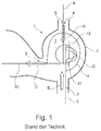
- FIG. 1 is a schematic sectional view of an air duct housing 1 according to the prior art shown, which is exemplary part of a ventilation, heating or air conditioning, not shown.
- the air guide housing 1 has a chamber 2 with a chamber wall 3.
- a first air inlet opening 4 is arranged on the chamber wall 3.
- the first air inlet opening 4 serves as an example as a fresh air inlet opening 5, which is fluidly connected to a fresh air duct, not shown.
- the first air inlet opening 4 has a round or angular cross-section.
- the cross-sectional area of the first air inlet opening 4 forms a first plane which is arranged substantially perpendicular to a first axis 6.
- the first axis 6 penetrates by way of example the chamber 2 and cuts in the in the FIG. 1
- the inflow direction of the fresh air flowing through the first air inlet opening 4 into the chamber 2 is in the illustrated embodiment Essentially arranged parallel to the first axis and is in the FIG. 1 represented by the arrow A.
- a second air inlet opening 7 is arranged in a region of the chamber wall 3 which is substantially opposite the first air inlet opening 4, a second air inlet opening 7 is arranged.
- the second air inlet opening 7 is fluidly connected by way of example to a circulating air duct, not shown, and / or to the vehicle cabin.
- the second air inlet opening 7 by way of example on a round or square cross-section.
- the cross-sectional area of the second air inlet opening 7 forms a second plane, which is arranged substantially perpendicular to a second axis 8.
- the second axis 8 penetrates by way of example the chamber 2 and cuts in the in the FIG. 1
- the inflow direction of the circulating air flowing through the second air inlet opening 7 into the chamber 2 is arranged substantially parallel to the second axis 8 and is in the FIG. 1 represented by the arrow B.
- the first axis 6 is arranged substantially parallel to the second axis 8.
- the air guide housing 1 has an air outlet opening 9 formed in the chamber wall 3.
- the air outlet opening 9 is fluidly connected by way of example to an air outlet duct, not shown, and / or to the vehicle cabin.
- the air outlet opening 9 by way of example on a round or square cross-section.
- the cross-sectional area of the air outlet opening 9 forms a third plane, which is arranged substantially perpendicular to a third axis 10.
- the third axis 10 projects through the chamber 2 by way of example.
- the outflow direction of the air flowing out of the chamber 2 through the air outlet opening 9 is arranged substantially perpendicular to the first axis 6 and perpendicular to the second axis 8 and is in the FIG. 1 represented by the arrow C.
- the third axis 10 and the second axis 8 are arranged substantially to one another.
- An arranged between the third axis 10 and the second axis 8 angle ⁇ is about 270 °,
- an impeller 11 is arranged, which sucks air via the first air inlet opening 4 and / or the second air inlet opening 7 into the chamber 2 and conveys through the air outlet opening 9 from the chamber 2.
- the impeller 11 is rotatably mounted about a fourth axis 12.
- the fourth axis 12 is arranged substantially parallel to the first axis 6 and parallel to the second axis 8.
- the fourth axis 12 is arranged perpendicular to the third axis 10.
- the direction of rotation of the impeller 11 is in the FIG. 1 indicated by the arrow D.
- the direction of rotation D forms a circular area which perpendicularly intersects the cross-sectional areas formed by the first air inlet opening 4 and by the second air inlet opening 7 and by the air outlet opening 9.
- the first air inlet opening 4 is located in front of the second air inlet opening 7 in the direction of rotation D of the fan 11
- the second air inlet opening 7 is located in the direction of rotation D of the fan 11 in front of the air outlet opening 9.
- FIG. 2 a schematic sectional view of an air guide housing 110 is shown according to the invention, which is an example of part of a ventilation, heating or air conditioning, not shown.
- the air guide housing 110 has a chamber 120 with a chamber wall 130.
- a first air inlet opening 140 is arranged at the chamber wall 130.
- the first air inlet opening 140 serves as an example as a fresh air inlet opening 150, which is fluidly connected to a fresh air duct, not shown.
- the first air inlet opening 140 has, for example, a round or angular cross-section.
- the cross-sectional area of the first air inlet opening 140 forms a first plane which is arranged substantially perpendicular to a first axis 160.
- the first axis 160 penetrates by way of example the chamber 120 and cuts in the in the FIG. 2
- the inflow direction of the fresh air flowing through the first air inlet opening 140 into the chamber 120 is arranged substantially parallel to the first axis and is in the illustrated embodiment FIG. 1 represented by the arrow A1.
- a second air inlet opening 170 is arranged on the chamber wall 130.
- the second air inlet opening 170 is fluidly connected by way of example to a circulating air duct, not shown, and / or to the vehicle cabin.
- the second air inlet opening 170 has, for example, a round or angular cross-section.
- the cross-sectional area of the second air inlet opening 170 forms a second plane, which is arranged substantially perpendicular to a second axis 180.
- the second axis 180 penetrates by way of example the chamber 120 and cuts in the in the FIG. 2
- the inflow direction of the circulating air flowing through the second air inlet opening 170 into the chamber 120 is arranged substantially parallel to the second axis and is in the illustrated embodiment FIG. 2 represented by the arrow B1.
- the first axis 160 is arranged substantially perpendicular to the second axis 180.
- the air guide housing 110 has an air outlet opening 190 formed in the chamber wall 130.
- the air outlet 190 is exemplarily fluidly connected to an air outlet duct, not shown, and / or to the vehicle cabin.
- the air outlet opening 190 by way of example has a round or angular cross-section.
- the Cross-sectional area of the air outlet opening 190 forms a third plane, which is arranged substantially perpendicular to a third axis 1100.
- the third axis 1100 projects through the chamber 120 by way of example.
- the outflow direction of the air flowing out of the chamber 120 through the air outlet opening 190 is arranged substantially perpendicular to the first axis 160 and parallel to the second axis 180 and is in the FIG. 2 represented by the arrow C1.
- the third axis 1100 and the second axis 180 are arranged substantially parallel to one another. Consequently, the angle ⁇ between the third axis 1100 and the second axis 180 is about 180 °.
- an impeller 1111 is arranged, which draws air into the chamber 120 via the first air inlet opening 140 and / or the second air inlet opening 170 and conveys it out of the chamber 120 through the air outlet opening 190.
- the impeller 1111 is rotatably supported about a fourth axis 1112.
- the fourth axis 1112 is disposed substantially parallel to the first axis 160 and perpendicular to the second axis 180.
- the fourth axis 1112 is disposed perpendicular to the third axis 1100.
- the direction of rotation of the impeller 1111 is in the FIG. 2 indicated by the arrow D1.
- the direction of rotation D1 forms a circular area which perpendicularly intersects the cross-sectional areas formed by the first air inlet opening 140 and by the second air inlet opening 170 and by the air outlet opening 190.
- the first air inlet opening 140 lies in the direction of rotation D1 of the impeller 1111 in front of the second air inlet opening 170 and the second air inlet opening 170 is located in the direction of rotation D1 of the impeller 1111 in front of the air outlet opening 190.
- FIG. 3 a diagram is shown, which in the FIG. 1 described and counting the state of the art air duct housing 1 with the in the FIG. 2 illustrated air guide housing 110 according to the invention compares.
- the comparison relates to the respective noise level (expressed in decibels) with respect to the angle ⁇ , ⁇ , in which the inflow direction of the circulating air flowing into the chamber 2, 120 through the second air inlet opening 7, 170 to the outflow direction through the air outlet opening 9 , 190 out of the chamber 2, 120 outflowing air is arranged.
- the angle ⁇ is about 270 °.
- the depth band range is approximately 70 decibels.
- the angle ⁇ is about 180 °. It lies in the in the FIG. 3 shown curve area at about 68 decibels.
Landscapes
- Engineering & Computer Science (AREA)
- Mechanical Engineering (AREA)
- Physics & Mathematics (AREA)
- Thermal Sciences (AREA)
- Chemical & Material Sciences (AREA)
- General Engineering & Computer Science (AREA)
- Chemical Kinetics & Catalysis (AREA)
- Combustion & Propulsion (AREA)
- Air-Conditioning For Vehicles (AREA)
Description
- Die Erfindung betrifft ein Luftführungsgehäuse gemäß dem Oberbegriff von Anspruch 1. Darüber hinaus betrifft die Erfindung eine Belüftungs-, Heizungs- oder Klimaanlage gemäß Anspruch 10.
- Die
DE 199 44 175 A1 offenbart eine Heizungs- oder Klimaanlage für ein Kraftfahrzeug mit einem saugseitig einem Gebläse vorgeschalteten Luftansauggehäuse, dem jeweils wenigstens ein wechselweise verschließbarer und öffenbarer Lufteinlass für Frischluft und Umluft zugeordnet ist, wobei wenigstens ein Luftfilter zum Reinigen von Frischluft vorgesehen und druckseitig dem Gebläse ein Luftverteilergehäuse nachgeschaltet ist. Dem Gebläse ist ein dem Luftansauggehäuse zugeordneter Ansaugstutzen mit Lufteinlassöffnungen vorgeordnet, an dem umfangseitig eine Dosiereinrichtung für die Lufteinlassöffnungen angelagert ist, wobei die Achse der Dosiereinrichtung koaxial zur Achse des Gebläses in Fahrzeugrichtung verläuft. - Die im oben genannten Stand der Technik offenbarte Vorrichtung weist im Betrieb einen relativ hohen Pegel an unerwünschten Betriebsgeräuschen auf. Eine Belüftungs-, Heizungs- oder Klimaanlage, dessen Luftführungsgehäuse im Betrieb eine leisere Geräuschkulisse aufweist, ist daher von Vorteil.
- Es ist die Aufgabe der Erfindung, ein verbessertes Luftführungsgehäuse bereitzustellen, welches im Betrieb einen niedrigeren Geräuschpegel aufweist. Darüber hinaus ist es die Aufgabe der Erfindung, eine Belüftungs-, Heizungs-oder Klimaanlage bereitzustellen, welche ein solches Luftführungsgehäuse aufweist.
- Die Aufgabe zum Luftführungsgehäuse wird mit den Merkmalen von Anspruch 1 gelöst.
- Ein Ausführungsbeispiel der Erfindung betrifft ein Luftführungsgehäuse, insbesondere für eine Belüftungs-, Heizungs- oder Klimaanlage eines Fahrzeugs, mit zumindest einer ersten Lufteinlassöffnung, wobei die zumindest eine erste Lufteinlassöffnung eine Querschnittsfläche aufweist, welche im Wesentlichen vertikal zu einer ersten Achse angeordnet ist, und mit zumindest einer zweiten Lufteinlassöffnung, wobei die zumindest eine zweite Lufteinlassöffnung eine Querschnittsfläche aufweist, welche im Wesentlichen vertikal zu einer zweiten Achse angeordnet ist, und mit zumindest einer Luftauslassöffnung, wobei die zumindest eine Luftauslassöffnung eine Querschnittsfläche aufweist, welche im Wesentlichen vertikal zu einer dritten Achse angeordnet ist, und mit einem Gebläserad zum Ansaugen von Luft in das Luftführungsgehäuse. Dabei sind die zweite Achse und die dritte Achse im Wesentlichen parallel zueinander angeordnet. In vorteilhafter Weise werden hierdurch die bei der Förderung der Luft durch das Luftführungsgehäuse entstehenden Geräusche reduziert.
- Bei einer besonders vorteilhaften Ausführungsform des Luftführungsgehäuses sind die erste Achse und die zweite Achse in einem Winkel von etwa 90° zueinander angeordnet und die erste Achse und die dritte Achse sind in einem Winkel von etwa 90° zueinander angeordnet. Der durch die Luftförderung im Luftführungsgehäuse gebildete Geräuschpegel wird dadurch noch einmal deutlich reduziert.
- Ein zusätzliches Ausführungsbeispiel des Luftführungsgehäuses sieht vor, dass die zumindest eine erste Lufteinlassöffnung mit einem Frischluftkanal fluidverbunden ist, wobei über den Frischluftkanal Frischluft aus der Umgebung des Fahrzeugs durch die zumindest eine erste Lufteinlassöffnung in das Luftführungsgehäuse ansaugbar ist.
- Bei einer weiteren Ausführungsform des Luftführungsgehäuses ist durch die zumindest eine zweite Lufteinlassöffnung Umluft aus einem Umluftkanal und/oder aus einer Kabine des Fahrzeugs in das Luftführungsgehäuse ansaugbar.
- Ein vorteilhaftes Ausführungsbeispiel des Luftführungsgehäuses sieht vor, dass das Gebläserad drehbar um eine vierte Achse gelagert ist, wobei die zweite Achse und die vierte Achse im Wesentlichen in einem Winkel von etwa 90° zueinander angeordnet sind. Eine direkte Schallabstrahlung in einen Fahrzeuginnenraum wird dadurch vermieden.
- Bei einer zusätzlichen Ausführungsform des Luftführungsgehäuses sind die erste Achse und die vierte Achse im Wesentlichen parallel zueinander angeordnet und die dritte Achse und die vierte Achse sind in einem Winkel von etwa 90° zueinander angeordnet.
- Bei einem weiteren Ausführungsbeispiel des Luftführungsgehäuses ist in der Luftströmungsrichtung hinter der zumindest einen Luftauslassöffnung ein Luftfilter angeordnet.
- Eine zusätzliche Ausführungsform des Luftführungsgehäuses sieht vor, dass im Bereich der zumindest einen ersten Lufteinlassöffnung und/oder im Bereich der zumindest einen zweiten Lufteinlassöffnung und/oder im Bereich der zumindest einen Luftauslassöffnung Verbindungselemente zur Verbindung des Luftführungsgehäuses mit einer Fluidkanalanordnung ausgebildet sind. Hierdurch lässt sich das Luftführungsgehäuse auf einfache Weise in eine Belüftungs-, Heizungs- oder Klimaanlage integrieren.
- Bei einem weiteren Ausführungsbeispiel des Luftführungsgehäuses ist im Bereich des Luftführungsgehäuses und/oder in einem zum Luftführungsgehäuse benachbart angeordneten Bereich zumindest eine Luftstromsteuervorrichtung und/oder zumindest eine Luftstromsteuerungsanordnung zum wahlweisen und/oder anteilig dosierbaren Ansaugen und/oder Beströmen des Luftführungsgehäuses mit Frischluft und/oder Umluft angeordnet.
- Die Aufgabe zur Belüftungs-, Heizungs- oder Klimaanlage wird mit den Merkmalen von Anspruch 10 gelöst.
- Ein Ausführungsbeispiel der Belüftungs-, Heizungs- oder Klimaanlage sieht vor, dass die Belüftungs-, Heizungs- oder Klimaanlage zumindest ein gemäß der oben genannten Beschreibung ausgebildetes Luftführungsgehäuse aufweist.
- Nachstehend wird die Erfindung auf der Grundlage zumindest eines Ausführungsbeispiels anhand der Figuren der Zeichnung näher erläutert. Es zeigen:
- Fig. 1
- eine Schnittansicht eines Luftführungsgehäuses gemäß dem Stand der Technik,
- Fig. 2
- eine Schnittansicht eines Ausführungsbeispiels eines erfindungsgemäßen Luftführungsgehäuses, und
- Fig. 3
- ein Kurvendiagramm.
- In
Figur 1 ist eine schematische Schnittansicht eines Luftführungsgehäuses 1 gemäß dem Stand der Technik dargestellt, welches beispielhaft Teil einer nicht dargestellten Belüftungs-, Heizungs- oder Klimaanlage ist. Das Luftführungsgehäuse 1 weist eine Kammer 2 mit einer Kammerwand 3 auf. An der Kammerwand 3 ist eine erste Lufteinlassöffnung 4 angeordnet. Die erste Lufteinlassöffnung 4 dient beispielhaft als Frischlufteinlassöffnung 5, welche mit einem nicht dargestellten Frischluftkanal fluidverbunden ist. Die erste Lufteinlassöffnung 4 weist beispielhaft einen rund oder eckig ausgebildeten Querschnitt auf. Die Querschnittsfläche der ersten Lufteinlassöffnung 4 bildet dabei eine erste Ebene, welche im Wesentlichen senkrecht zu einer ersten Achse 6 angeordnet ist. Die erste Achse 6 durchragt dabei beispielhaft die Kammer 2 und schneidet in der in derFigur 1 dargestellten Ausführungsform in etwa den Mittelpunkt der Kammer 2. Die Einströmrichtung der durch die erste Lufteinlassöffnung 4 in die Kammer 2 strömenden Frischluft, ist im Wesentlichen parallel zur ersten Achse angeordnet und ist in derFigur 1 durch den Pfeil A dargestellt. - In einem der ersten Lufteinlassöffnung 4 im Wesentlichen gegenüberliegenden Bereich der Kammerwand 3 ist eine zweite Lufteinlassöffnung 7 angeordnet. Die zweite Lufteinlassöffnung 7 ist beispielhaft mit einem nicht dargestellten Umluftkanal und/oder mit der Fahrzeugkabine fluidverbunden. Dabei weist die zweite Lufteinlassöffnung 7 beispielhaft einen runden oder eckig ausgebildeten Querschnitt auf. Die Querschnittsfläche der zweiten Lufteinlassöffnung 7 bildet eine zweite Ebene, welche im Wesentlichen senkrecht zu einer zweiten Achse 8 angeordnet ist. Die zweite Achse 8 durchragt dabei beispielhaft die Kammer 2 und schneidet in der in der
Figur 1 dargestellten Ausführungsform in etwa den Mittelpunkt der Kammer 2. Die Einströmrichtung der durch die zweite Lufteinlassöffnung 7 in die Kammer 2 strömenden Umluft, ist im Wesentlichen parallel zur zweiten Achse 8 angeordnet und ist in derFigur 1 durch den Pfeil B dargestellt. - Die erste Achse 6 ist im Wesentlichen parallel zur zweiten Achse 8 angeordnet.
- Darüber hinaus weist das Luftführungsgehäuse 1 eine in der Kammerwand 3 ausgebildete Luftauslassöffnung 9 auf. Die Luftauslassöffnung 9 ist beispielhaft mit einem nicht dargestellten Luftauslasskanal und/oder mit der Fahrzeugkabine fluidverbunden. Dabei weist die Luftauslassöffnung 9 beispielhaft einen rund oder eckig ausgebildeten Querschnitt auf. Die Querschnittsfläche der Luftauslassöffnung 9 bildet eine dritte Ebene, welche im Wesentlichen senkrecht zu einer dritten Achse 10 angeordnet ist. Die dritte Achse 10 durchragt dabei beispielhaft die Kammer 2. Die Ausströmrichtung der durch die Luftauslassöffnung 9 aus der Kammer 2 strömenden Luft, ist im Wesentlichen senkrecht zur ersten Achse 6 sowie senkrecht zur zweiten Achse 8 angeordnet und ist in der
Figur 1 durch den Pfeil C dargestellt. - Die dritte Achse 10 und die zweite Achse 8 sind dabei im Wesentlichen zueinander angeordnet. Ein zwischen der dritten Achse 10 und der zweiten Achse 8 angeordneter Winkel α beträgt dabei etwa 270°,
In der Kammer 3 ist ein Gebläserad 11 angeordnet, welches Luft über die erste Lufteinlassöffnung 4 und/oder die zweite Lufteinlassöffnung 7 in die Kammer 2 einsaugt und durch die Luftauslassöffnung 9 aus der Kammer 2 fördert. - Das Gebläserad 11 ist um eine vierte Achse 12 drehbar gelagert. Die vierte Achse 12 ist im Wesentlichen parallel zur ersten Achse 6 und parallel zur zweiten Achse 8 angeordnet. Darüber hinaus ist die vierte Achse 12 senkrecht zur dritten Achse 10 angeordnet.
- Die Drehrichtung des Gebläserads 11 ist in der
Figur 1 durch den Pfeil D gekennzeichnet. Die Drehrichtung D bildet eine Kreisfläche, welche die von der ersten Lufteinlassöffnung 4 und von der zweiten Lufteinlassöffnung 7 sowie von der Luftauslassöffnung 9 gebildeten Querschnittsflächen senkrecht schneidet. Dabei liegt die erste Lufteinlassöffnung 4 in der Drehrichtung D des Gebläserads 11 vor der zweiten Lufteinlassöffnung 7 und die zweite Lufteinlassöffnung 7 liegt in der Drehrichtung D des Gebläserads 11 vor der Luftauslassöffnung 9. - In der
Figur 2 ist eine schematische Schnittansicht eines Luftführungsgehäuses 110 gemäß der Erfindung dargestellt, welches beispielhaft Teil einer nicht dargestellten Belüftungs-, Heizungs- oder Klimaanlage ist. Das Luftführungsgehäuse 110 weist eine Kammer 120 mit einer Kammerwand 130 auf. An der Kammerwand 130 ist eine erste Lufteinlassöffnung 140 angeordnet. Die erste Lufteinlassöffnung 140 dient beispielhaft als Frischlufteinlassöffnung 150, welche mit einem nicht dargestellten Frischluftkanal fluidverbunden ist. Die erste Lufteinlassöffnung 140 weist beispielhaft einen runden oder eckig ausgebildeten Querschnitt auf. - Die Querschnittsfläche der ersten Lufteinlassöffnung 140 bildet dabei eine erste Ebene, welche im Wesentlichen senkrecht zu einer ersten Achse 160 angeordnet ist. Die ersten Achse 160 durchragt dabei beispielhaft die Kammer 120 und schneidet in der in der
Figur 2 dargestellten Ausführungsform in etwa den Mittelpunkt der Kammer 120. Die Einströmrichtung der durch die erste Lufteinlassöffnung 140 in die Kammer 120 strömenden Frischluft, ist im Wesentlichen parallel zur ersten Achse angeordnet und ist in derFigur 1 durch den Pfeil A1 dargestellt. - Darüber hinaus ist an der Kammerwand 130 eine zweite Lufteinlassöffnung 170 angeordnet. Die zweite Lufteinlassöffnung 170 ist beispielhaft mit einem nicht dargestellten Umluftkanal und/oder mit der Fahrzeugkabine fluidverbunden. Dabei weist die zweite Lufteinlassöffnung 170 beispielhaft einen runden oder eckig ausgebildeten Querschnitt auf. Die Querschnittsfläche der zweiten Lufteinlassöffnung 170 bildet eine zweite Ebene, welche im Wesentlichen senkrecht zu einer zweiten Achse 180 angeordnet ist. Die zweite Achse 180 durchragt dabei beispielhaft die Kammer 120 und schneidet in der in der
Figur 2 dargestellten Ausführungsform in etwa den Mittelpunkt der Kammer 120. Die Einströmrichtung der durch die zweite Lufteinlassöffnung 170 in die Kammer 120 strömende Umluft, ist im Wesentlichen parallel zur zweiten Achse angeordnet und ist in derFigur 2 durch den Pfeil B1 dargestellt. - Die erste Achse 160 ist im Wesentlichen senkrecht zur zweiten Achse 180 angeordnet.
- Darüber hinaus weist das Luftführungsgehäuse 110 eine in der Kammerwand 130 ausgebildete Luftauslassöffnung 190 auf. Die Luftauslassöffnung 190 ist beispielhaft mit einem nicht dargestellten Luftauslasskanal und/oder mit der Fahrzeugkabine fluidverbunden. Dabei weist die Luftauslassöffnung 190 beispielhaft einen rund oder eckig ausgebildeten Querschnitt auf. Die Querschnittsfläche der Luftauslassöffnung 190 bildet eine dritte Ebene, welche im Wesentlichen senkrecht zu einer dritten Achse 1100 angeordnet ist. Die dritte Achse 1100 durchragt dabei beispielhaft die Kammer 120. Die Ausströmrichtung der durch die Luftauslassöffnung 190 aus der Kammer 120 strömenden Luft, ist im Wesentlichen senkrecht zur ersten Achse 160 sowie parallel zur zweiten Achse 180 angeordnet und ist in der
Figur 2 durch den Pfeil C1 dargestellt. - Die dritte Achse 1100 und die zweite Achse 180 sind dabei im Wesentlichen parallel zueinander angeordnet. Folglich beträgt der Winkel β zwischen der dritten Achse 1100 und der zweiten Achse 180 etwa 180°.
- In der Kammer 120 ist ein Gebläserad 1111 angeordnet, welches Luft über die erste Lufteinlassöffnung 140 und/oder die zweite Lufteinlassöffnung 170 in die Kammer 120 einsaugt und durch die Luftauslassöffnung 190 aus der Kammer 120 fördert.
- Das Gebläserad 1111 ist um eine vierte Achse 1112 drehbar gelagert. Die vierte Achse 1112 ist im Wesentlichen parallel zur ersten Achse 160 und senkrecht zur zweiten Achse 180 angeordnet. Darüber hinaus ist die vierte Achse 1112 senkrecht zur dritten Achse 1100 angeordnet.
- Die Drehrichtung des Gebläserads 1111 ist in der
Figur 2 durch den Pfeil D1 gekennzeichnet. Die Drehrichtung D1 bildet eine Kreisfläche, welche die von der ersten Lufteinlassöffnung 140 und von der zweiten Lufteinlassöffnung 170 sowie von der Luftauslassöffnung 190 gebildeten Querschnittsflächen senkrecht schneidet. Dabei liegt die erste Lufteinlassöffnung 140 in der Drehrichtung D1 des Gebläserads 1111 vor der zweiten Lufteinlassöffnung 170 und die zweite Lufteinlassöffnung 170 liegt in der Drehrichtung D1 des Gebläserads 1111 vor der Luftauslassöffnung 190. - In der
Figur 3 ist ein Diagramm dargestellt, welches das in derFigur 1 beschriebene und zum Stand der Technik zählende Luftführungsgehäuse 1 mit dem in derFigur 2 dargestellten erfindungsgemäßen Luftführungsgehäuse 110 vergleicht. Der Vergleich betrifft den jeweils im Tiefenbandbereich auftretenden Lärmpegel (angegeben in Dezibel) in Bezug auf den Winkel α, β, in welchem die Einströmrichtung der durch die zweite Lufteinlassöffnung 7, 170 in die Kammer 2, 120 einströmenden Umluft zu der Ausströmrichtung der durch Luftauslassöffnung 9, 190 aus der Kammer 2, 120 ausströmenden Luft angeordnet ist. - In dem in der
Figur 1 dargestellten Beispiel eines Luftführungsgehäuses 1 aus dem Stand der Technik beträgt der Winkel α etwa 270°. Dabei liegt der Tiefenbandbereich bei ca. 70 Dezibel. - Für das in der
Figur 2 dargestellte Ausführungsbeispiel eines erfindungsgemäßen Luftführungsgehäuses 110 beträgt der Winkel β etwa 180°. Dabei liegt der in dem in derFigur 3 dargestellten Kurvendiagramm gezeigte Tiefenbandbereich bei ca. 68 Dezibel.
Claims (10)
- Luftführungsgehäuse (110), insbesondere für eine Belüftungs-, Heizungs- oder Klimaanlage eines Fahrzeugs, mit zumindest einer ersten Lufteinlassöffnung (140), wobei die zumindest eine erste Lufteinlassöffnung (140) eine Querschnittsfläche aufweist, welche im Wesentlichen vertikal zu einer ersten Achse (160) angeordnet ist, und mit zumindest einer zweiten Lufteinlassöffnung (170), wobei die zumindest eine zweite Lufteinlassöffnung (170) eine Querschnittsfläche aufweist, welche im Wesentlichen vertikal zu einer zweiten Achse (180) angeordnet ist, und mit zumindest einer Luftauslassöffnung (190), wobei die zumindest eine Luftauslassöffnung (190) eine Querschnittsfläche aufweist, welche im Wesentlichen vertikal zu einer dritten Achse (1100) angeordnet ist, und mit einem Gebläserad (1111) zum Ansaugen von Luft in das Luftführungsgehäuse (110), dadurch gekennzeichnet, dass die zweite Achse (180) und die dritte Achse (1100) im Wesentlichen parallel zueinander angeordnet sind.
- Luftführungsgehäuse (110) nach Anspruch 1, dadurch gekennzeichnet, dass die erste Achse (160) und die zweite Achse (180) in einem Winkel von etwa 90° zueinander angeordnet sind und die erste Achse (160) und die dritte Achse (1100) in einem Winkel von etwa 90° zueinander angeordnet sind.
- Luftführungsgehäuse (110) nach Anspruch 1 oder 2, dadurch gekennzeichnet, dass die zumindest eine erste Lufteinlassöffnung (140) mit einem Frischluftkanal fluidverbunden ist, wobei über den Frischluftkanal Frischluft aus der Umgebung des Fahrzeugs durch die zumindest eine erste Lufteinlassöffnung (140) in das Luftführungsgehäuse (110) ansaugbar ist.
- Luftführungsgehäuse (110) nach Anspruch 1, 2 oder 3, dadurch gekennzeichnet, dass durch die zumindest eine zweite Lufteinlassöffnung (170) Umluft aus einem Umluftkanal und/oder aus einer Kabine des Fahrzeugs in das Luftführungsgehäuse (110) ansaugbar ist.
- Luftführungsgehäuse (110) nach einem der vorhergehenden Ansprüche, dadurch gekennzeichnet, dass das Gebläserad (1111) drehbar um eine vierte Achse (1112) gelagert ist, wobei die zweite Achse (180) und die vierte Achse (1112) im Wesentlichen in einem Winkel von etwa 90° zueinander angeordnet sind.
- Luftführungsgehäuse (110) nach Anspruch 5, dadurch gekennzeichnet, dass die erste Achse (160) und die vierte Achse (1112) im Wesentlichen parallel zueinander angeordnet sind und die dritte Achse (1100) und die vierte Achse (1112) in einem Winkel von etwa 90° zueinander angeordnet sind.
- Luftführungsgehäuse (110) nach einem der vorhergehenden Ansprüche, dadurch gekennzeichnet, dass in einer Luftströmungsrichtung hinter der zumindest einen Luftauslassöffnung (190) ein Luftfilter angeordnet ist.
- Luftführungsgehäuse (110) nach einem der vorhergehenden Ansprüche, dadurch gekennzeichnet, dass im Bereich der zumindest einen ersten Lufteinlassöffnung (140) und/oder im Bereich der zumindest einen zweiten Lufteinlassöffnung (170) und/oder im Bereich der zumindest einen Luftauslassöffnung (190) Verbindungselemente zur Verbindung des Luftführungsgehäuses (110) mit einer Fluidkanalanordnung ausgebildet sind.
- Luftführungsgehäuse (110) nach einem der vorhergehenden Ansprüche, dadurch gekennzeichnet, dass im Bereich des Luftführungsgehäuses (110) und/oder in einem zum Luftführungsgehäuse (110) benachbart angeordneten Bereich zumindest eine Luftstromsteuervorrichtung und/oder zumindest eine Luftstromsteuerungsanordnung zum wahlweisen und/oder anteilig dosierbaren Ansaugen und/oder Beströmen des Luftführungsgehäuses (110) mit Frischluft und/oder Umluft angeordnet ist.
- Belüftungs-, Heizungs- oder Klimaanlage, dadurch gekennzeichnet, dass die Belüftungs-, Heizungs- oder Klimaanlage zumindest ein gemäß einem der Ansprüche 1 bis 9 ausgebildetes Luftführungsgehäuse (110) aufweist.
Applications Claiming Priority (1)
| Application Number | Priority Date | Filing Date | Title |
|---|---|---|---|
| DE102015217245.7A DE102015217245A1 (de) | 2015-09-09 | 2015-09-09 | Luftführungsgehäuse und eine Belüftungs-, Heizungs- oder Klimaanlage mit einem solchen Luftführungsgehäuse |
Publications (2)
| Publication Number | Publication Date |
|---|---|
| EP3141410A1 true EP3141410A1 (de) | 2017-03-15 |
| EP3141410B1 EP3141410B1 (de) | 2021-07-21 |
Family
ID=56883722
Family Applications (1)
| Application Number | Title | Priority Date | Filing Date |
|---|---|---|---|
| EP16187644.6A Active EP3141410B1 (de) | 2015-09-09 | 2016-09-07 | Luftführungsgehäuse und eine belüftungs-, heizungs- oder klimaanlage mit einem solchen luftführungsgehäuse |
Country Status (4)
| Country | Link |
|---|---|
| US (1) | US10137753B2 (de) |
| EP (1) | EP3141410B1 (de) |
| CN (1) | CN106515355A (de) |
| DE (1) | DE102015217245A1 (de) |
Cited By (1)
| Publication number | Priority date | Publication date | Assignee | Title |
|---|---|---|---|---|
| CN111249820A (zh) * | 2019-11-20 | 2020-06-09 | 浙江零跑科技有限公司 | 一种用于汽车空调的吸尘结构 |
Families Citing this family (4)
| Publication number | Priority date | Publication date | Assignee | Title |
|---|---|---|---|---|
| US10465640B1 (en) * | 2017-10-31 | 2019-11-05 | Supertrap Industries, Inc | Active cold air intake system |
| CN111867915B (zh) * | 2018-03-15 | 2023-01-20 | 西门子交通有限公司 | 混合器以及用于对轨道交通工具进行空气调节的装置 |
| CN108837538B (zh) * | 2018-06-25 | 2021-01-05 | 湖南尚花科技有限公司 | 一种冷焰火喷发设备 |
| CN112856701B (zh) * | 2021-02-01 | 2022-06-07 | 山东立威微波设备有限公司 | 一种家用空气净化无极光波杀菌消毒装置 |
Citations (4)
| Publication number | Priority date | Publication date | Assignee | Title |
|---|---|---|---|---|
| DE19944175A1 (de) | 1999-09-15 | 2001-03-29 | Daimler Chrysler Ag | Heizungs- oder Klimaanlage |
| US20060065389A1 (en) * | 2004-09-29 | 2006-03-30 | Lin-Jie Huang | Cooling system for an instrument panel of a vehicle |
| US20120000363A1 (en) * | 2010-06-30 | 2012-01-05 | Denso Corporation | Air filter device |
| US20120180998A1 (en) * | 2011-01-14 | 2012-07-19 | Denso Corporation | Air conditioner |
Family Cites Families (18)
| Publication number | Priority date | Publication date | Assignee | Title |
|---|---|---|---|---|
| CH495267A (de) * | 1968-02-23 | 1970-08-31 | Luwa Ag | Leitgehäuse für mit Staub oder Fasern beladene oder verunreinigte Luft |
| DE59300637D1 (de) * | 1993-12-20 | 1995-10-26 | Siemens Ag | Heiz- bzw. Klimagerät, insbesondere zum Einbau in ein Kraftfahrzeug. |
| EP0771392B1 (de) * | 1994-07-15 | 1998-04-15 | Siemens Aktiengesellschaft | Luftansaugvorrichtung mit variabler saugrohrlänge |
| DE10031991B4 (de) * | 2000-06-30 | 2004-02-05 | Valeo Klimasysteme Gmbh | Luftklappe |
| JP3603065B2 (ja) | 2001-11-07 | 2004-12-15 | 株式会社日本クライメイトシステムズ | 車両用空調装置 |
| KR101078758B1 (ko) * | 2004-03-11 | 2011-11-02 | 한라공조주식회사 | 차량용 후석 공기조화장치 |
| DE102004015829B4 (de) * | 2004-03-31 | 2016-11-24 | Valeo Klimasysteme Gmbh | Ansaugstutzen |
| JP4333747B2 (ja) * | 2007-01-29 | 2009-09-16 | トヨタ自動車株式会社 | 車両用内燃機関の吸気装置 |
| WO2008093496A1 (ja) * | 2007-01-30 | 2008-08-07 | Panasonic Corporation | 消音ボックス付送風機 |
| BRPI0803051B1 (pt) * | 2008-06-30 | 2019-01-15 | Petróleo Brasileiro S/A - Petrobras | separador ciclônico de suspensão gás-sólido e método de separação |
| US8556570B2 (en) * | 2009-05-29 | 2013-10-15 | Hakko Corporation | Smoke and fume removal assembly with dual suction modes |
| EP2335799A1 (de) * | 2009-12-04 | 2011-06-22 | Nifco UK Limited | Trennsystem zum Trennen von festen oder flüssigen, in einem Gas verteilten Partikeln |
| GB201106573D0 (en) * | 2011-04-19 | 2011-06-01 | Siemens Vai Metals Tech Ltd | Cyclone |
| WO2013080339A1 (ja) | 2011-11-30 | 2013-06-06 | トヨタ自動車株式会社 | 車両前部構造 |
| JP5909648B2 (ja) * | 2012-08-01 | 2016-04-27 | パナソニックIpマネジメント株式会社 | 発熱体収納装置 |
| DE102012018198A1 (de) * | 2012-09-14 | 2014-03-20 | Man Truck & Bus Ag | Luftführendes Gehäuse für eine Heizungs- und/oder Klimaanlage, insbesondere für Fahrzeuge |
| US9359981B1 (en) * | 2015-05-08 | 2016-06-07 | Brunswick Corporation | Outboard motor with sound enhancement device and method for modifying sounds produced by air intake system of an outboard motor |
| DE102016202445A1 (de) * | 2016-02-17 | 2017-08-17 | Mahle International Gmbh | Klimaanlage eines Kraftfahrzeugs |
-
2015
- 2015-09-09 DE DE102015217245.7A patent/DE102015217245A1/de not_active Withdrawn
-
2016
- 2016-08-19 US US15/241,397 patent/US10137753B2/en active Active
- 2016-09-07 CN CN201610806966.3A patent/CN106515355A/zh active Pending
- 2016-09-07 EP EP16187644.6A patent/EP3141410B1/de active Active
Patent Citations (4)
| Publication number | Priority date | Publication date | Assignee | Title |
|---|---|---|---|---|
| DE19944175A1 (de) | 1999-09-15 | 2001-03-29 | Daimler Chrysler Ag | Heizungs- oder Klimaanlage |
| US20060065389A1 (en) * | 2004-09-29 | 2006-03-30 | Lin-Jie Huang | Cooling system for an instrument panel of a vehicle |
| US20120000363A1 (en) * | 2010-06-30 | 2012-01-05 | Denso Corporation | Air filter device |
| US20120180998A1 (en) * | 2011-01-14 | 2012-07-19 | Denso Corporation | Air conditioner |
Cited By (1)
| Publication number | Priority date | Publication date | Assignee | Title |
|---|---|---|---|---|
| CN111249820A (zh) * | 2019-11-20 | 2020-06-09 | 浙江零跑科技有限公司 | 一种用于汽车空调的吸尘结构 |
Also Published As
| Publication number | Publication date |
|---|---|
| US20170066302A1 (en) | 2017-03-09 |
| EP3141410B1 (de) | 2021-07-21 |
| CN106515355A (zh) | 2017-03-22 |
| US10137753B2 (en) | 2018-11-27 |
| DE102015217245A1 (de) | 2017-03-09 |
Similar Documents
| Publication | Publication Date | Title |
|---|---|---|
| EP3141410B1 (de) | Luftführungsgehäuse und eine belüftungs-, heizungs- oder klimaanlage mit einem solchen luftführungsgehäuse | |
| DE102015203185A1 (de) | Schnorcheleinlassschmutzträgheitsabscheider für Verbrennungsmotor | |
| DE102007014836B4 (de) | Luftfilter- und Gebläsevorrichtung für Fahrzeugbelüftungsanlagen | |
| EP3334942B2 (de) | Dunstabzugsvorrichtung mit diagonalventilator | |
| DE1503510A1 (de) | Ventilator | |
| DE102015113785A1 (de) | Kühlluftschnittstelle in einem Gebläsegehäuse | |
| EP2322866B2 (de) | Drallauslass zur Belüftung von Räumen | |
| DE102011011975A1 (de) | Luftansaugvorrichtung einer Fahrzeuginnenraumbelüftungsanlage und Fahrzeuginnenraumbelüftungsanlage | |
| DE102019109401B4 (de) | Lüftereinrichtung zum Ansaugen und Ableiten von Wrasen nach unterhalb eines Kochfeldes und Kochfeld | |
| EP2781384B1 (de) | Gebläseanordnung für Kabinenfiltration | |
| EP2626644A1 (de) | Lüftungsbauteil, umfassend ein kanalförmiges Gehäuse mit umlaufend angeordneten Gehäusewandungen | |
| DE202016102277U1 (de) | Dunstabzugsvorrichtung mit Diagonalventilator | |
| DE102014102146A1 (de) | Luftansaugvorrichtung eines Kraftfahrzeugklimagerätes | |
| DE102017201331A1 (de) | Gebläse für Dunstabzugsvorrichtung und Dunstabzugsvorrichtung | |
| DE102022115066A1 (de) | Dunstabzug und Kombinationsgerät | |
| EP3574265B1 (de) | Dunstabzugshaube | |
| DE102004015829A1 (de) | Ansaugstutzen | |
| DE60101764T2 (de) | Fahrzeugklimaanlage | |
| EP2899468B1 (de) | Gargerät mit einem Luftschacht und einem Zuleitkanal | |
| DE102006019328A1 (de) | Ansauggebläseanordnung, insbesondere für eine Kraftfahrzeug-Klimaanlage | |
| EP2080910B1 (de) | Gebläse, insbesondere Fahrzeuggebläse | |
| EP2450204A2 (de) | Klimaanlage für ein Kraftfahrzeug | |
| DE2004185C3 (de) | Vorrichtung zum Beeinflussen der Lufttemperatur im Innenraum eines Kraftfahrzeuges | |
| DE1503624C (de) | Gehäuse fur eine radiale Turbo Ar beitsmaschine | |
| DE102014018034B4 (de) | Luftkanal für eine Fahrzeugbelüftung |
Legal Events
| Date | Code | Title | Description |
|---|---|---|---|
| PUAI | Public reference made under article 153(3) epc to a published international application that has entered the european phase |
Free format text: ORIGINAL CODE: 0009012 |
|
| STAA | Information on the status of an ep patent application or granted ep patent |
Free format text: STATUS: THE APPLICATION HAS BEEN PUBLISHED |
|
| AK | Designated contracting states |
Kind code of ref document: A1 Designated state(s): AL AT BE BG CH CY CZ DE DK EE ES FI FR GB GR HR HU IE IS IT LI LT LU LV MC MK MT NL NO PL PT RO RS SE SI SK SM TR |
|
| AX | Request for extension of the european patent |
Extension state: BA ME |
|
| STAA | Information on the status of an ep patent application or granted ep patent |
Free format text: STATUS: REQUEST FOR EXAMINATION WAS MADE |
|
| 17P | Request for examination filed |
Effective date: 20170915 |
|
| RBV | Designated contracting states (corrected) |
Designated state(s): AL AT BE BG CH CY CZ DE DK EE ES FI FR GB GR HR HU IE IS IT LI LT LU LV MC MK MT NL NO PL PT RO RS SE SI SK SM TR |
|
| STAA | Information on the status of an ep patent application or granted ep patent |
Free format text: STATUS: EXAMINATION IS IN PROGRESS |
|
| 17Q | First examination report despatched |
Effective date: 20171206 |
|
| APBK | Appeal reference recorded |
Free format text: ORIGINAL CODE: EPIDOSNREFNE |
|
| APBN | Date of receipt of notice of appeal recorded |
Free format text: ORIGINAL CODE: EPIDOSNNOA2E |
|
| APBR | Date of receipt of statement of grounds of appeal recorded |
Free format text: ORIGINAL CODE: EPIDOSNNOA3E |
|
| APAF | Appeal reference modified |
Free format text: ORIGINAL CODE: EPIDOSCREFNE |
|
| APBT | Appeal procedure closed |
Free format text: ORIGINAL CODE: EPIDOSNNOA9E |
|
| GRAP | Despatch of communication of intention to grant a patent |
Free format text: ORIGINAL CODE: EPIDOSNIGR1 |
|
| STAA | Information on the status of an ep patent application or granted ep patent |
Free format text: STATUS: GRANT OF PATENT IS INTENDED |
|
| INTG | Intention to grant announced |
Effective date: 20210409 |
|
| GRAS | Grant fee paid |
Free format text: ORIGINAL CODE: EPIDOSNIGR3 |
|
| GRAA | (expected) grant |
Free format text: ORIGINAL CODE: 0009210 |
|
| STAA | Information on the status of an ep patent application or granted ep patent |
Free format text: STATUS: THE PATENT HAS BEEN GRANTED |
|
| AK | Designated contracting states |
Kind code of ref document: B1 Designated state(s): AL AT BE BG CH CY CZ DE DK EE ES FI FR GB GR HR HU IE IS IT LI LT LU LV MC MK MT NL NO PL PT RO RS SE SI SK SM TR |
|
| REG | Reference to a national code |
Ref country code: GB Ref legal event code: FG4D Free format text: NOT ENGLISH |
|
| REG | Reference to a national code |
Ref country code: CH Ref legal event code: EP |
|
| REG | Reference to a national code |
Ref country code: DE Ref legal event code: R096 Ref document number: 502016013431 Country of ref document: DE |
|
| REG | Reference to a national code |
Ref country code: AT Ref legal event code: REF Ref document number: 1412273 Country of ref document: AT Kind code of ref document: T Effective date: 20210815 |
|
| REG | Reference to a national code |
Ref country code: IE Ref legal event code: FG4D Free format text: LANGUAGE OF EP DOCUMENT: GERMAN |
|
| REG | Reference to a national code |
Ref country code: LT Ref legal event code: MG9D |
|
| REG | Reference to a national code |
Ref country code: NL Ref legal event code: MP Effective date: 20210721 |
|
| PG25 | Lapsed in a contracting state [announced via postgrant information from national office to epo] |
Ref country code: RS Free format text: LAPSE BECAUSE OF FAILURE TO SUBMIT A TRANSLATION OF THE DESCRIPTION OR TO PAY THE FEE WITHIN THE PRESCRIBED TIME-LIMIT Effective date: 20210721 Ref country code: SE Free format text: LAPSE BECAUSE OF FAILURE TO SUBMIT A TRANSLATION OF THE DESCRIPTION OR TO PAY THE FEE WITHIN THE PRESCRIBED TIME-LIMIT Effective date: 20210721 Ref country code: HR Free format text: LAPSE BECAUSE OF FAILURE TO SUBMIT A TRANSLATION OF THE DESCRIPTION OR TO PAY THE FEE WITHIN THE PRESCRIBED TIME-LIMIT Effective date: 20210721 Ref country code: LT Free format text: LAPSE BECAUSE OF FAILURE TO SUBMIT A TRANSLATION OF THE DESCRIPTION OR TO PAY THE FEE WITHIN THE PRESCRIBED TIME-LIMIT Effective date: 20210721 Ref country code: BG Free format text: LAPSE BECAUSE OF FAILURE TO SUBMIT A TRANSLATION OF THE DESCRIPTION OR TO PAY THE FEE WITHIN THE PRESCRIBED TIME-LIMIT Effective date: 20211021 Ref country code: NL Free format text: LAPSE BECAUSE OF FAILURE TO SUBMIT A TRANSLATION OF THE DESCRIPTION OR TO PAY THE FEE WITHIN THE PRESCRIBED TIME-LIMIT Effective date: 20210721 Ref country code: PT Free format text: LAPSE BECAUSE OF FAILURE TO SUBMIT A TRANSLATION OF THE DESCRIPTION OR TO PAY THE FEE WITHIN THE PRESCRIBED TIME-LIMIT Effective date: 20211122 Ref country code: NO Free format text: LAPSE BECAUSE OF FAILURE TO SUBMIT A TRANSLATION OF THE DESCRIPTION OR TO PAY THE FEE WITHIN THE PRESCRIBED TIME-LIMIT Effective date: 20211021 Ref country code: ES Free format text: LAPSE BECAUSE OF FAILURE TO SUBMIT A TRANSLATION OF THE DESCRIPTION OR TO PAY THE FEE WITHIN THE PRESCRIBED TIME-LIMIT Effective date: 20210721 Ref country code: FI Free format text: LAPSE BECAUSE OF FAILURE TO SUBMIT A TRANSLATION OF THE DESCRIPTION OR TO PAY THE FEE WITHIN THE PRESCRIBED TIME-LIMIT Effective date: 20210721 |
|
| PG25 | Lapsed in a contracting state [announced via postgrant information from national office to epo] |
Ref country code: PL Free format text: LAPSE BECAUSE OF FAILURE TO SUBMIT A TRANSLATION OF THE DESCRIPTION OR TO PAY THE FEE WITHIN THE PRESCRIBED TIME-LIMIT Effective date: 20210721 Ref country code: LV Free format text: LAPSE BECAUSE OF FAILURE TO SUBMIT A TRANSLATION OF THE DESCRIPTION OR TO PAY THE FEE WITHIN THE PRESCRIBED TIME-LIMIT Effective date: 20210721 Ref country code: GR Free format text: LAPSE BECAUSE OF FAILURE TO SUBMIT A TRANSLATION OF THE DESCRIPTION OR TO PAY THE FEE WITHIN THE PRESCRIBED TIME-LIMIT Effective date: 20211022 |
|
| REG | Reference to a national code |
Ref country code: DE Ref legal event code: R097 Ref document number: 502016013431 Country of ref document: DE |
|
| PG25 | Lapsed in a contracting state [announced via postgrant information from national office to epo] |
Ref country code: DK Free format text: LAPSE BECAUSE OF FAILURE TO SUBMIT A TRANSLATION OF THE DESCRIPTION OR TO PAY THE FEE WITHIN THE PRESCRIBED TIME-LIMIT Effective date: 20210721 |
|
| REG | Reference to a national code |
Ref country code: CH Ref legal event code: PL |
|
| REG | Reference to a national code |
Ref country code: BE Ref legal event code: MM Effective date: 20210930 |
|
| PLBE | No opposition filed within time limit |
Free format text: ORIGINAL CODE: 0009261 |
|
| STAA | Information on the status of an ep patent application or granted ep patent |
Free format text: STATUS: NO OPPOSITION FILED WITHIN TIME LIMIT |
|
| PG25 | Lapsed in a contracting state [announced via postgrant information from national office to epo] |
Ref country code: SM Free format text: LAPSE BECAUSE OF FAILURE TO SUBMIT A TRANSLATION OF THE DESCRIPTION OR TO PAY THE FEE WITHIN THE PRESCRIBED TIME-LIMIT Effective date: 20210721 Ref country code: SK Free format text: LAPSE BECAUSE OF FAILURE TO SUBMIT A TRANSLATION OF THE DESCRIPTION OR TO PAY THE FEE WITHIN THE PRESCRIBED TIME-LIMIT Effective date: 20210721 Ref country code: RO Free format text: LAPSE BECAUSE OF FAILURE TO SUBMIT A TRANSLATION OF THE DESCRIPTION OR TO PAY THE FEE WITHIN THE PRESCRIBED TIME-LIMIT Effective date: 20210721 Ref country code: MC Free format text: LAPSE BECAUSE OF FAILURE TO SUBMIT A TRANSLATION OF THE DESCRIPTION OR TO PAY THE FEE WITHIN THE PRESCRIBED TIME-LIMIT Effective date: 20210721 Ref country code: EE Free format text: LAPSE BECAUSE OF FAILURE TO SUBMIT A TRANSLATION OF THE DESCRIPTION OR TO PAY THE FEE WITHIN THE PRESCRIBED TIME-LIMIT Effective date: 20210721 Ref country code: CZ Free format text: LAPSE BECAUSE OF FAILURE TO SUBMIT A TRANSLATION OF THE DESCRIPTION OR TO PAY THE FEE WITHIN THE PRESCRIBED TIME-LIMIT Effective date: 20210721 Ref country code: AL Free format text: LAPSE BECAUSE OF FAILURE TO SUBMIT A TRANSLATION OF THE DESCRIPTION OR TO PAY THE FEE WITHIN THE PRESCRIBED TIME-LIMIT Effective date: 20210721 |
|
| 26N | No opposition filed |
Effective date: 20220422 |
|
| GBPC | Gb: european patent ceased through non-payment of renewal fee |
Effective date: 20211021 |
|
| PG25 | Lapsed in a contracting state [announced via postgrant information from national office to epo] |
Ref country code: LU Free format text: LAPSE BECAUSE OF NON-PAYMENT OF DUE FEES Effective date: 20210907 Ref country code: IT Free format text: LAPSE BECAUSE OF FAILURE TO SUBMIT A TRANSLATION OF THE DESCRIPTION OR TO PAY THE FEE WITHIN THE PRESCRIBED TIME-LIMIT Effective date: 20210721 Ref country code: IE Free format text: LAPSE BECAUSE OF NON-PAYMENT OF DUE FEES Effective date: 20210907 Ref country code: GB Free format text: LAPSE BECAUSE OF NON-PAYMENT OF DUE FEES Effective date: 20211021 Ref country code: FR Free format text: LAPSE BECAUSE OF NON-PAYMENT OF DUE FEES Effective date: 20210921 Ref country code: BE Free format text: LAPSE BECAUSE OF NON-PAYMENT OF DUE FEES Effective date: 20210930 |
|
| PG25 | Lapsed in a contracting state [announced via postgrant information from national office to epo] |
Ref country code: LI Free format text: LAPSE BECAUSE OF NON-PAYMENT OF DUE FEES Effective date: 20210930 Ref country code: CH Free format text: LAPSE BECAUSE OF NON-PAYMENT OF DUE FEES Effective date: 20210930 |
|
| REG | Reference to a national code |
Ref country code: AT Ref legal event code: MM01 Ref document number: 1412273 Country of ref document: AT Kind code of ref document: T Effective date: 20210907 |
|
| PG25 | Lapsed in a contracting state [announced via postgrant information from national office to epo] |
Ref country code: AT Free format text: LAPSE BECAUSE OF NON-PAYMENT OF DUE FEES Effective date: 20210907 |
|
| PG25 | Lapsed in a contracting state [announced via postgrant information from national office to epo] |
Ref country code: HU Free format text: LAPSE BECAUSE OF FAILURE TO SUBMIT A TRANSLATION OF THE DESCRIPTION OR TO PAY THE FEE WITHIN THE PRESCRIBED TIME-LIMIT; INVALID AB INITIO Effective date: 20160907 |
|
| PG25 | Lapsed in a contracting state [announced via postgrant information from national office to epo] |
Ref country code: CY Free format text: LAPSE BECAUSE OF FAILURE TO SUBMIT A TRANSLATION OF THE DESCRIPTION OR TO PAY THE FEE WITHIN THE PRESCRIBED TIME-LIMIT Effective date: 20210721 |
|
| PG25 | Lapsed in a contracting state [announced via postgrant information from national office to epo] |
Ref country code: MK Free format text: LAPSE BECAUSE OF FAILURE TO SUBMIT A TRANSLATION OF THE DESCRIPTION OR TO PAY THE FEE WITHIN THE PRESCRIBED TIME-LIMIT Effective date: 20210721 |
|
| PG25 | Lapsed in a contracting state [announced via postgrant information from national office to epo] |
Ref country code: TR Free format text: LAPSE BECAUSE OF FAILURE TO SUBMIT A TRANSLATION OF THE DESCRIPTION OR TO PAY THE FEE WITHIN THE PRESCRIBED TIME-LIMIT Effective date: 20210721 |
|
| P01 | Opt-out of the competence of the unified patent court (upc) registered |
Effective date: 20240527 |
|
| PG25 | Lapsed in a contracting state [announced via postgrant information from national office to epo] |
Ref country code: MT Free format text: LAPSE BECAUSE OF FAILURE TO SUBMIT A TRANSLATION OF THE DESCRIPTION OR TO PAY THE FEE WITHIN THE PRESCRIBED TIME-LIMIT Effective date: 20210721 |
|
| PGFP | Annual fee paid to national office [announced via postgrant information from national office to epo] |
Ref country code: DE Payment date: 20250919 Year of fee payment: 10 |