EP3136889B2 - Système de génération d'aérosol à chauffage électrique et procédé - Google Patents
Système de génération d'aérosol à chauffage électrique et procédé Download PDFInfo
- Publication number
- EP3136889B2 EP3136889B2 EP15717908.6A EP15717908A EP3136889B2 EP 3136889 B2 EP3136889 B2 EP 3136889B2 EP 15717908 A EP15717908 A EP 15717908A EP 3136889 B2 EP3136889 B2 EP 3136889B2
- Authority
- EP
- European Patent Office
- Prior art keywords
- power supply
- electrically heated
- ambient temperature
- charging device
- aerosol
- Prior art date
- Legal status (The legal status is an assumption and is not a legal conclusion. Google has not performed a legal analysis and makes no representation as to the accuracy of the status listed.)
- Active
Links
- 239000000758 substrate Substances 0.000 claims description 47
- 238000000034 method Methods 0.000 claims description 36
- 238000010438 heat treatment Methods 0.000 claims description 28
- 238000007599 discharging Methods 0.000 claims description 27
- 238000012544 monitoring process Methods 0.000 claims description 7
- 241000208125 Nicotiana Species 0.000 description 18
- 235000002637 Nicotiana tabacum Nutrition 0.000 description 18
- 230000000391 smoking effect Effects 0.000 description 18
- 239000000443 aerosol Substances 0.000 description 16
- 238000009529 body temperature measurement Methods 0.000 description 12
- 239000007787 solid Substances 0.000 description 9
- 238000005259 measurement Methods 0.000 description 8
- 230000000007 visual effect Effects 0.000 description 8
- DNIAPMSPPWPWGF-UHFFFAOYSA-N Propylene glycol Chemical compound CC(O)CO DNIAPMSPPWPWGF-UHFFFAOYSA-N 0.000 description 6
- 150000001875 compounds Chemical class 0.000 description 6
- 238000010586 diagram Methods 0.000 description 5
- 239000000463 material Substances 0.000 description 5
- PEDCQBHIVMGVHV-UHFFFAOYSA-N Glycerine Chemical compound OCC(O)CO PEDCQBHIVMGVHV-UHFFFAOYSA-N 0.000 description 4
- 238000001816 cooling Methods 0.000 description 4
- 239000000796 flavoring agent Substances 0.000 description 4
- 235000019634 flavors Nutrition 0.000 description 4
- 239000007788 liquid Substances 0.000 description 4
- OKTJSMMVPCPJKN-UHFFFAOYSA-N Carbon Chemical compound [C] OKTJSMMVPCPJKN-UHFFFAOYSA-N 0.000 description 2
- CWYNVVGOOAEACU-UHFFFAOYSA-N Fe2+ Chemical compound [Fe+2] CWYNVVGOOAEACU-UHFFFAOYSA-N 0.000 description 2
- HBBGRARXTFLTSG-UHFFFAOYSA-N Lithium ion Chemical compound [Li+] HBBGRARXTFLTSG-UHFFFAOYSA-N 0.000 description 2
- 229910052799 carbon Inorganic materials 0.000 description 2
- 235000019504 cigarettes Nutrition 0.000 description 2
- 239000000835 fiber Substances 0.000 description 2
- 235000011187 glycerol Nutrition 0.000 description 2
- 239000008187 granular material Substances 0.000 description 2
- 229910000625 lithium cobalt oxide Inorganic materials 0.000 description 2
- 229910001416 lithium ion Inorganic materials 0.000 description 2
- GELKBWJHTRAYNV-UHFFFAOYSA-K lithium iron phosphate Chemical compound [Li+].[Fe+2].[O-]P([O-])([O-])=O GELKBWJHTRAYNV-UHFFFAOYSA-K 0.000 description 2
- BFZPBUKRYWOWDV-UHFFFAOYSA-N lithium;oxido(oxo)cobalt Chemical compound [Li+].[O-][Co]=O BFZPBUKRYWOWDV-UHFFFAOYSA-N 0.000 description 2
- 239000004745 nonwoven fabric Substances 0.000 description 2
- 239000008188 pellet Substances 0.000 description 2
- 239000000843 powder Substances 0.000 description 2
- 238000012546 transfer Methods 0.000 description 2
- SNICXCGAKADSCV-JTQLQIEISA-N (-)-Nicotine Chemical compound CN1CCC[C@H]1C1=CC=CN=C1 SNICXCGAKADSCV-JTQLQIEISA-N 0.000 description 1
- 229920003043 Cellulose fiber Polymers 0.000 description 1
- 230000015556 catabolic process Effects 0.000 description 1
- 229920002678 cellulose Polymers 0.000 description 1
- 239000001913 cellulose Substances 0.000 description 1
- 238000002485 combustion reaction Methods 0.000 description 1
- 239000000470 constituent Substances 0.000 description 1
- 238000006731 degradation reaction Methods 0.000 description 1
- 238000013461 design Methods 0.000 description 1
- 239000006260 foam Substances 0.000 description 1
- 239000011888 foil Substances 0.000 description 1
- 239000012634 fragment Substances 0.000 description 1
- 239000000499 gel Substances 0.000 description 1
- 210000004072 lung Anatomy 0.000 description 1
- 239000011159 matrix material Substances 0.000 description 1
- 229960002715 nicotine Drugs 0.000 description 1
- SNICXCGAKADSCV-UHFFFAOYSA-N nicotine Natural products CN1CCCC1C1=CC=CN=C1 SNICXCGAKADSCV-UHFFFAOYSA-N 0.000 description 1
- 229920000642 polymer Polymers 0.000 description 1
- 239000002002 slurry Substances 0.000 description 1
- 239000000779 smoke Substances 0.000 description 1
Images


Classifications
-
- A—HUMAN NECESSITIES
- A24—TOBACCO; CIGARS; CIGARETTES; SIMULATED SMOKING DEVICES; SMOKERS' REQUISITES
- A24B—MANUFACTURE OR PREPARATION OF TOBACCO FOR SMOKING OR CHEWING; TOBACCO; SNUFF
- A24B15/00—Chemical features or treatment of tobacco; Tobacco substitutes, e.g. in liquid form
- A24B15/10—Chemical features of tobacco products or tobacco substitutes
- A24B15/16—Chemical features of tobacco products or tobacco substitutes of tobacco substitutes
- A24B15/167—Chemical features of tobacco products or tobacco substitutes of tobacco substitutes in liquid or vaporisable form, e.g. liquid compositions for electronic cigarettes
-
- A—HUMAN NECESSITIES
- A24—TOBACCO; CIGARS; CIGARETTES; SIMULATED SMOKING DEVICES; SMOKERS' REQUISITES
- A24F—SMOKERS' REQUISITES; MATCH BOXES; SIMULATED SMOKING DEVICES
- A24F40/00—Electrically operated smoking devices; Component parts thereof; Manufacture thereof; Maintenance or testing thereof; Charging means specially adapted therefor
- A24F40/20—Devices using solid inhalable precursors
-
- A—HUMAN NECESSITIES
- A24—TOBACCO; CIGARS; CIGARETTES; SIMULATED SMOKING DEVICES; SMOKERS' REQUISITES
- A24F—SMOKERS' REQUISITES; MATCH BOXES; SIMULATED SMOKING DEVICES
- A24F40/00—Electrically operated smoking devices; Component parts thereof; Manufacture thereof; Maintenance or testing thereof; Charging means specially adapted therefor
- A24F40/40—Constructional details, e.g. connection of cartridges and battery parts
- A24F40/46—Shape or structure of electric heating means
-
- A—HUMAN NECESSITIES
- A24—TOBACCO; CIGARS; CIGARETTES; SIMULATED SMOKING DEVICES; SMOKERS' REQUISITES
- A24F—SMOKERS' REQUISITES; MATCH BOXES; SIMULATED SMOKING DEVICES
- A24F40/00—Electrically operated smoking devices; Component parts thereof; Manufacture thereof; Maintenance or testing thereof; Charging means specially adapted therefor
- A24F40/50—Control or monitoring
- A24F40/53—Monitoring, e.g. fault detection
-
- A—HUMAN NECESSITIES
- A24—TOBACCO; CIGARS; CIGARETTES; SIMULATED SMOKING DEVICES; SMOKERS' REQUISITES
- A24F—SMOKERS' REQUISITES; MATCH BOXES; SIMULATED SMOKING DEVICES
- A24F40/00—Electrically operated smoking devices; Component parts thereof; Manufacture thereof; Maintenance or testing thereof; Charging means specially adapted therefor
- A24F40/90—Arrangements or methods specially adapted for charging batteries thereof
-
- A—HUMAN NECESSITIES
- A61—MEDICAL OR VETERINARY SCIENCE; HYGIENE
- A61M—DEVICES FOR INTRODUCING MEDIA INTO, OR ONTO, THE BODY; DEVICES FOR TRANSDUCING BODY MEDIA OR FOR TAKING MEDIA FROM THE BODY; DEVICES FOR PRODUCING OR ENDING SLEEP OR STUPOR
- A61M15/00—Inhalators
- A61M15/06—Inhaling appliances shaped like cigars, cigarettes or pipes
-
- H—ELECTRICITY
- H02—GENERATION; CONVERSION OR DISTRIBUTION OF ELECTRIC POWER
- H02J—CIRCUIT ARRANGEMENTS OR SYSTEMS FOR SUPPLYING OR DISTRIBUTING ELECTRIC POWER; SYSTEMS FOR STORING ELECTRIC ENERGY
- H02J7/00—Circuit arrangements for charging or depolarising batteries or for supplying loads from batteries
- H02J7/00032—Circuit arrangements for charging or depolarising batteries or for supplying loads from batteries characterised by data exchange
- H02J7/00036—Charger exchanging data with battery
-
- H—ELECTRICITY
- H02—GENERATION; CONVERSION OR DISTRIBUTION OF ELECTRIC POWER
- H02J—CIRCUIT ARRANGEMENTS OR SYSTEMS FOR SUPPLYING OR DISTRIBUTING ELECTRIC POWER; SYSTEMS FOR STORING ELECTRIC ENERGY
- H02J7/00—Circuit arrangements for charging or depolarising batteries or for supplying loads from batteries
- H02J7/00032—Circuit arrangements for charging or depolarising batteries or for supplying loads from batteries characterised by data exchange
- H02J7/00038—Circuit arrangements for charging or depolarising batteries or for supplying loads from batteries characterised by data exchange using passive battery identification means, e.g. resistors or capacitors
- H02J7/00041—Circuit arrangements for charging or depolarising batteries or for supplying loads from batteries characterised by data exchange using passive battery identification means, e.g. resistors or capacitors in response to measured battery parameters, e.g. voltage, current or temperature profile
-
- H—ELECTRICITY
- H02—GENERATION; CONVERSION OR DISTRIBUTION OF ELECTRIC POWER
- H02J—CIRCUIT ARRANGEMENTS OR SYSTEMS FOR SUPPLYING OR DISTRIBUTING ELECTRIC POWER; SYSTEMS FOR STORING ELECTRIC ENERGY
- H02J7/00—Circuit arrangements for charging or depolarising batteries or for supplying loads from batteries
- H02J7/0047—Circuit arrangements for charging or depolarising batteries or for supplying loads from batteries with monitoring or indicating devices or circuits
- H02J7/0048—Detection of remaining charge capacity or state of charge [SOC]
-
- H—ELECTRICITY
- H02—GENERATION; CONVERSION OR DISTRIBUTION OF ELECTRIC POWER
- H02J—CIRCUIT ARRANGEMENTS OR SYSTEMS FOR SUPPLYING OR DISTRIBUTING ELECTRIC POWER; SYSTEMS FOR STORING ELECTRIC ENERGY
- H02J7/00—Circuit arrangements for charging or depolarising batteries or for supplying loads from batteries
- H02J7/007—Regulation of charging or discharging current or voltage
- H02J7/007188—Regulation of charging or discharging current or voltage the charge cycle being controlled or terminated in response to non-electric parameters
- H02J7/007192—Regulation of charging or discharging current or voltage the charge cycle being controlled or terminated in response to non-electric parameters in response to temperature
- H02J7/007194—Regulation of charging or discharging current or voltage the charge cycle being controlled or terminated in response to non-electric parameters in response to temperature of the battery
-
- H—ELECTRICITY
- H05—ELECTRIC TECHNIQUES NOT OTHERWISE PROVIDED FOR
- H05B—ELECTRIC HEATING; ELECTRIC LIGHT SOURCES NOT OTHERWISE PROVIDED FOR; CIRCUIT ARRANGEMENTS FOR ELECTRIC LIGHT SOURCES, IN GENERAL
- H05B1/00—Details of electric heating devices
- H05B1/02—Automatic switching arrangements specially adapted to apparatus ; Control of heating devices
- H05B1/0227—Applications
- H05B1/023—Industrial applications
- H05B1/0244—Heating of fluids
-
- H—ELECTRICITY
- H05—ELECTRIC TECHNIQUES NOT OTHERWISE PROVIDED FOR
- H05B—ELECTRIC HEATING; ELECTRIC LIGHT SOURCES NOT OTHERWISE PROVIDED FOR; CIRCUIT ARRANGEMENTS FOR ELECTRIC LIGHT SOURCES, IN GENERAL
- H05B1/00—Details of electric heating devices
- H05B1/02—Automatic switching arrangements specially adapted to apparatus ; Control of heating devices
- H05B1/0227—Applications
- H05B1/0252—Domestic applications
-
- A—HUMAN NECESSITIES
- A24—TOBACCO; CIGARS; CIGARETTES; SIMULATED SMOKING DEVICES; SMOKERS' REQUISITES
- A24F—SMOKERS' REQUISITES; MATCH BOXES; SIMULATED SMOKING DEVICES
- A24F40/00—Electrically operated smoking devices; Component parts thereof; Manufacture thereof; Maintenance or testing thereof; Charging means specially adapted therefor
- A24F40/10—Devices using liquid inhalable precursors
-
- H—ELECTRICITY
- H05—ELECTRIC TECHNIQUES NOT OTHERWISE PROVIDED FOR
- H05B—ELECTRIC HEATING; ELECTRIC LIGHT SOURCES NOT OTHERWISE PROVIDED FOR; CIRCUIT ARRANGEMENTS FOR ELECTRIC LIGHT SOURCES, IN GENERAL
- H05B2203/00—Aspects relating to Ohmic resistive heating covered by group H05B3/00
- H05B2203/021—Heaters specially adapted for heating liquids
-
- Y—GENERAL TAGGING OF NEW TECHNOLOGICAL DEVELOPMENTS; GENERAL TAGGING OF CROSS-SECTIONAL TECHNOLOGIES SPANNING OVER SEVERAL SECTIONS OF THE IPC; TECHNICAL SUBJECTS COVERED BY FORMER USPC CROSS-REFERENCE ART COLLECTIONS [XRACs] AND DIGESTS
- Y02—TECHNOLOGIES OR APPLICATIONS FOR MITIGATION OR ADAPTATION AGAINST CLIMATE CHANGE
- Y02E—REDUCTION OF GREENHOUSE GAS [GHG] EMISSIONS, RELATED TO ENERGY GENERATION, TRANSMISSION OR DISTRIBUTION
- Y02E60/00—Enabling technologies; Technologies with a potential or indirect contribution to GHG emissions mitigation
- Y02E60/10—Energy storage using batteries
Definitions
- the present invention relates to a method of controlling an electrically heated aerosol-generating system, a method of controlling an electrically heated aerosol-generating device, and the associated electrically heated aerosol-generating system and device.
- An example of such an electrical system having a portable device and a primary charging device is an electrically operated smoking disclosed in WO 2013/102612 A2 .
- Electrically operated smoking systems significantly reduce sidestream smoke, as compared to lit-end smoking devices, while permitting a consumer to selectively activate the smoking system during the smoking experience.
- Electrically operated smoking systems typically include an aerosol-generating device having a housing for receiving an aerosol-generating article or a smoking article, heating elements to generate an aerosol, a power source and the necessary electronic circuitry.
- the circuitry may be, for example, circuitry for controlling the heating and charging of the aerosol-generating device. Having a portable device and primary charging device provides the advantage of a small aerosol-generating device being the portable device that is easy to hold and use, but also the ability to quickly and conveniently recharge the aerosol generating device for repeated use.
- the electrically heated aerosol-generating system comprises a charging device comprising a rechargeable power supply, and an electrically heated aerosol-generating device configured to receive an aerosol-generating substrate comprising a rechargeable power supply, and at least one electrical heating element.
- the method comprises: monitoring the ambient temperature adjacent the charging device; determining a charging current, for charging the rechargeable power supply of the charging device, in dependence on the ambient temperature adjacent the charging device; and charging the rechargeable power supply of the charging device at the determined charging current.
- the charging current is less than about 0.1 C; when the ambient temperature adjacent the charging device is within a second pre-determined temperature range, the charging current is greater than about 0.1 C; and, when the ambient temperature adjacent the charging device is above a pre-determined temperature, preventing charging of the rechargeable power of the charging device.
- Providing such a charging method enables the rechargeable power supply of the charging device to be recharged at a substantially optimum rate while reducing the risk of damaging the rechargeable power supply due to supplying a charging current that is too large for the current status of the power supply.
- C refers to a charging current, where 1 C equates to 1 A for a 1000 mAh rechargeable power supply. That is to say, the charging current at which the capacity of the rechargeable power supply is supplied in one hour.
- the first temperature range is between about 0 degrees C and about 10 degrees C
- the second temperature range is between about 10 degrees C and about 45 degrees C.
- the charging current is about 0.2 C.
- the rechargeable power supply of the charging device may be configured to allow fast charging of the power supply.
- the fast charging current is about 1 C.
- the method may comprise receiving an input from the user requesting that the charging device power supply is fast charged.
- the method may comprise determining the type of input power supply providing the power to recharge the charging device power supply, and determining the charging current accordingly. For example, if the input power supply cannot provide sufficient power to fast charge the rechargeable power supply, a charging current of 0.2 C is selected.
- first and second temperature ranges may be altered by one of ordinary skill in the art in dependence on the type of power supply used.
- the method may further comprise, when the rechargeable power supply of the charging device is being charged, indicating to a user which charging current is being provided to the power supply.
- the step of indicating which charging current is being provided preferably utilises at least one of: a visual indicator, such as a light, or series of lights; a sound, or series of sounds; and a tactile indicator.
- the tactile indicator may be a vibration or series of vibrations.
- the visual indicator may be a digital display. The digital display may provide an estimate of the time required to fully charge the charging device rechargeable power supply.
- the method preferably further comprises the steps of: determining a discharging current for the rechargeable power supply of the charging device, for charging the rechargeable power supply of the electrically heated aerosol-generating device; and charging the rechargeable power supply of the electrically heated aerosol-generating device at the determined discharge current.
- the discharging current is between about 0.1 C and about 0.3 C
- the discharging current is between about 0.8 C and about 1.2 C
- the ambient temperature adjacent the charging device is above a pre-determined temperature, preventing discharging of the rechargeable power of the charging device.
- Providing such a charging method enables the rechargeable power supply of the electrically heated aerosol-generating device to be recharged at a substantially optimum rate while reducing the risk of damaging the rechargeable power supply of the charging device due to providing a charging current that is too large for the current status of the power supply.
- the discharging current of the charging device power supply is substantially equivalent to the charging current of the electrically heated aerosol-generating device power supply.
- the third temperature range is between about -10 degrees C and about 0 degrees C
- the fourth temperature range is between about 0 degrees C and about 45 degrees C.
- the discharging current when the ambient temperature adjacent the charging device is within a third pre-determined temperature range, the discharging current is about 0.2 C, and when the ambient temperature adjacent the charging device is within a fourth pre-determined temperature range, the discharging current is about 1 C.
- the method may further comprise, when the rechargeable power supply of the charging device is being discharged, indicating to a user which discharging current is being provided to the power supply of the electrically heated aerosol-generating device.
- the step of indicating which discharging current is being provided preferably utilises at least one of: a visual indicator, such as a light, or series of lights; a sound, or series of sounds; and a tactile indicator.
- the tactile indicator may be a vibration or series of vibrations.
- the visual indicator may be an electronic display.
- the electronic display may provide an estimate of the time required to fully charge the electrically heated aerosol-generating device rechargeable power supply.
- the method preferably further comprises monitoring the ambient temperature adjacent the electrically heated aerosol-generating device, and providing a charging current to the rechargeable power supply of the electrically heated aerosol-generating device for recharging the power supply, in dependence on the ambient temperature adjacent the device.
- a charging current of about 10 C to the power supply
- the ambient temperature adjacent the electrically heated aerosol-generating device is without the pre-determined temperature range, preventing a charging current from being supplied to the power supply.
- the charging current of about 10 C is provided to the power supply when the pre-determined temperature range is about 0 degrees C to about 35 degrees C.
- the step of monitoring the ambient temperature is preferably performed with a frequency of about once per minute to about 5 time per minute.
- the ambient temperature is monitored once per minute.
- the step of determining a charging current is performed in dependence on an average of the monitored ambient temperature, preferably a weighted average. The average may be calculated using two, three, four or more measurements. Where used, the weighting applied to each successive measurement may decrease in an arithmetical progression, or in a geometric progression.
- a weighted average is used, where the weighted average is calculated using the present measured ambient temperature and the previous weighted average.
- the present measurement is given a weight of between about 10% and about 50%
- the previous weighted average is given a weight of between about 90% and about 50% accordingly.
- the weightings applied are preferably chosen in dependence on the overall heat transfer coefficient of the rechargeable power supply and surrounding air, such that the weighting produces an approximation to the heating rate or cooling rate of the rechargeable power supply.
- the initial weighted average is set to the first measurement of ambient temperature.
- the present measurement is given a weight of about 20%, and the previous weighted average is given a weight of about 80%.
- weightings approximate the relatively slow heating rate or cooling rate of the rechargeable power supplies of the systems described herein.
- the operational temperature range is between about 10 degrees C and about 70 degrees C, more preferably between about 12 degrees C and about 65 degrees C.
- the resistance of the heating element is low as compared to the resistance of the heating element when the temperature is within the operational range.
- the step of monitoring the ambient temperature adjacent the aerosol-generating device is preferably performed with a frequency of about once per minute to about 5 time per minute.
- a similar weighted average process is used as described above.
- the present measurement is given a weight of between about 10% and about 50%, and the previous weighted average is given a weight of between about 90% and about 50% accordingly.
- the weightings applied are preferably chosen in dependence on the overall heat transfer coefficient of the rechargeable power supply and surrounding air, such that the weighting produces an approximation to the heating rate or cooling rate of the rechargeable power supply.
- the initial weighted average is set to the first measurement of ambient temperature.
- the present measurement is given a weight of about 30%, and the previous weighted average is given a weight of about 70%.
- these weightings model the heating and cooling rate of the aerosol-generating device more effectively than the above described 20%/80% model used for the charging device weighted average because the thermal mass of the aerosol-generating device is less than the thermal mass of the charging device. Therefore, the aerosol-generating device heats or cools more quickly than the charging device.
- an electrically heated aerosol-generating system comprising: an electrically heated aerosol-generating device configured to receive an aerosol-generating substrate.
- the device comprises: a heating element; a rechargeable power supply for powering the heating element.
- the system further comprises a charging device configured to receive the electrically heated aerosol-generating device.
- the charging device comprises: a cavity for receiving the electrically heated aerosol-generating device; a rechargeable power supply for charging the rechargeable power supply of the electrically heated aerosol-generating device; a temperature sensor for sensing the ambient temperature adjacent the charging device; and a controller for controlling the supply of power to the charging device power supply from an external power source to recharge the power supply, in dependence on the ambient temperature adjacent the charging device.
- the controller when the ambient temperature adjacent the charging device is within a first pre-determined range, the controller is configured to provide a charging current of less than about 0.1 C; when the ambient temperature adjacent the charging device is within a second pre-determined range, the controller is configured to provide a charging current of greater than about 0.1 C; and when the ambient temperature adjacent the charging device is above a predetermined temperature, preventing charging of the rechargeable power of the charging device.
- Providing such a system enables the rechargeable power supply of the charging device to be recharged at a substantially optimum rate while reducing the risk of damaging the rechargeable power supply due to supplying a charging current that is too large for the current status of the power supply.
- the first temperature range is between about 0 degrees C and about 10 degrees C
- the second temperature range is between about 10 degrees C and about 45 degrees C.
- the charging current is about 0.2 C.
- the rechargeable power supply of the charging device may be configured to allow fast charging of the power supply.
- the fast charging current is about 1 C.
- the controller may be configured to receive an input from the user requesting that the charging device power supply is fast charged.
- the controller may be configured to determine the type of input power supply providing the power to recharge the charging device power supply, and determine the charging current accordingly. For example, if the input power supply cannot provide sufficient power to fast charge the rechargeable power supply, a charging current of 0.2 C is selected.
- the charging device comprises means for receiving external electrical power to recharge the rechargeable power supply.
- the charging device may further comprise an indicator for indicating to a user which charging current is being provided to the power supply, when the rechargeable power supply of the charging device is being charged.
- the indicator preferably comprises at least one of: a visual indicator, such as a light, or series of lights; a sound, or series of sounds; and a tactile indicator.
- the tactile indicator may be a vibration, or series of vibrations.
- the visual indicator may be a digital display. The digital display may provide an estimate of the time required to fully charge the charging device rechargeable power supply.
- the charging device controller is further configured to control the supply of power from the charging device power supply to the electrically heated aerosol-generating device power supply to recharge the power supply.
- the controller is configured to provide a discharging current between about 0.1 C and about 0.3 C to the power supply of the electrically heated aerosol-generating device; when the ambient temperature adjacent the charging device is within a fourth predetermined temperature range, the controller is configured to provide a discharging current between about 0.8 C and about 1.2 C to the power supply of the electrically heated aerosol-generating device; and when the ambient temperature adjacent the charging device is above a predetermined temperature, the controller is configured to prevent discharging of the rechargeable power of the charging device.
- Providing such a controller enables the rechargeable power supply of the electrically heated aerosol-generating device to be recharged at a substantially optimum rate while reducing the risk of damaging the rechargeable power supply of the charging device due to providing a charging current that is too large for the current status of the power supply.
- the discharging current of the charging device power supply is substantially equivalent to the charging current of the electrically heated aerosol-generating device power supply.
- the third temperature range is between about -10 degrees C and about 0 degrees C
- the fourth temperature range is between about 0 degrees C and about 45 degrees C.
- the discharging current when the ambient temperature adjacent the charging device is within a third pre-determined temperature range, the discharging current is about 0.2 C, and when the ambient temperature adjacent the charging device is within a fourth pre-determined temperature range, the discharging current is about 1 C.
- the charging device power supply is a lithium-ion battery. More preferably, the charging device power supply is a lithium cobalt oxide battery.
- the electrically heated aerosol-generating device power supply is also a lithium-ion battery. More preferably, the electrically heated aerosol-generating device power supply is a lithium iron phosphate battery.
- the charging device may further comprise an indicator for indicating toa user which discharging current is being provided to the power supply of the electrically heated aerosol-generating device when the rechargeable power supply of the charging device is being discharged.
- the indicator preferably comprises at least one of: a visual indicator, such as a light, or series of lights; a sound, or series of sounds; and a tactile indicator.
- the tactile indicator may be a vibration or series of vibrations.
- the visual indicator may be an electronic display. The electronic display may provide an estimate of the time required to fully charge the electrically heated aerosol-generating device rechargeable power supply.
- the charging device may include a display, or further display, (for example a digital display) indicating information to the user.
- the display may indicate smoking article consumption, energy usage or other information.
- the display may further indicate when the electrically heated aerosol-generating device power supply has sufficient charge to be used to consume a smoking article.
- the charging device further comprises a housing, and a lid attached to the housing.
- the lid is configured to close over the open end of the cavity, such that the electrically heated aerosol-generating device is not accessible when the lid is in the closed position.
- the charging device may further comprise means for preventing the supply of power to the electrically heated aerosol-generating device when the lid is open.
- the lid is preferably a hinge lid.
- the hinge extends across the top of the housing from the front wall to the back wall.
- the hinge may comprise a spring configured to retain the lid in the first position.
- the hinge may also comprise a damper configured to damp the motion of the lid when the lid is moved from the second position to the first position.
- the hinge may comprise a spring configured to retain the lid in the second position.
- the lid is preferably provided with means for retaining the lid in the first position, the retaining means being configured to provide sufficient force to overcome the force applied to the lid by the spring.
- the retaining means may comprise at least one magnet and at least one corresponding ferrous element.
- the at least one magnet being provided in the housing of the primary device, and the ferrous element being provided in the lid.
- the retaining means may be a latch type arrangement.
- the hinge lid may form the entire top of the housing.
- the hinge may be internal to the lid, and be adjacent a side wall of the housing.
- the housing of the charging device preferably comprises a front wall, a back wall, a bottom wall, a top wall, a first side wall and a second side wall.
- front, back, upper, “lower”, “side”, “top”, “bottom”, “left”, “right” and other terms used to describe relative positions of the components of the charging device and electrically heated aerosol-generating device refer to the charging device in an upright position with the opening of the cavity configured to receive the electrically heated aerosol-generating device at the top end.
- longitudinal refers to a direction from bottom to top or vice versa.
- transverse refers to a direction perpendicular to the longitudinal direction.
- the charging device may be a substantially rectangular parallelepiped comprising two wider walls spaced apart by two narrower side walls and top and bottom walls.
- the electrically heated aerosol-generating device is preferably elongate.
- the temperature sensor is preferably provided in contact with a wall of the charging device housing to enable an improved correlation between the measured temperature and the ambient temperature.
- the temperature sensor may be a thermocouple or a thermistor.
- the electrically heated aerosol-generating device of the system preferably further comprises a temperature sensor for sensing the ambient temperature adjacent the device.
- the charging device controller is preferably further configured to control the supply of power from the charging device power supply to the electrically heated aerosol-generating device power supply to recharge the power supply in dependence on the ambient temperature adjacent the electrically heated aerosol-generating device. Such that: when the ambient temperature adjacent the electrically heated aerosol-generating device is within a pre-determined temperature range, the controller is configured to provide a charging current of about 10 C to the power supply; and when the ambient temperature adjacent the electrically heated aerosol-generating device is without the pre-determined temperature range, the controller is configured to prevent a charging current from being supplied to the power supply.
- the charging current of about 10 C is provided to the power supply when the pre-determined temperature range is about 0 degrees C to about 35 degrees C.
- the temperature sensor of the electrically heated aerosol-generating device is preferably provided in contact with a wall of a housing of the device to enable an improved correlation between the measured temperature and the ambient temperature.
- the temperature sensor may be a thermocouple or a thermistor.
- the heating element may be used as a thermistor to measure the temperature.
- the device may further comprise an indicator for indicating to a user when the ambient temperature adjacent the device is without the pre-determined temperature range.
- the aerosol-generating device is designed to receive an aerosol-generating substrate in the form of an aerosol-generating article, and be held by a user during a smoking experience.
- the aerosol-generating device power supply is preferably adapted to heat up the aerosol-forming substrate to operating temperature before aerosol generating begins.
- the power supply in the aerosol-generating device is also adapted to maintain the temperature of the aerosol-forming substrate during the aerosol generation.
- the aerosol-generating device is preferably of a similar size to or slightly larger than a lit-end cigarette.
- the device can be held between the user's fingers in a similar way to a lit-end cigarette.
- the aerosol-generating substrate is preferably in the form of an aerosol-generating article, or a smoking article.
- the term 'aerosol-forming substrate' relates to a substrate capable of releasing volatile compounds that can form an aerosol. Such volatile compounds are released by heating the aerosol-forming substrate.
- An aerosol-forming substrate may be solid or liquid or comprise both solid and liquid components.
- An aerosol-forming substrate may be adsorbed, coated, impregnated or otherwise loaded onto a carrier or support.
- An aerosol-forming substrate may conveniently be part of an aerosol-generating article or smoking article.
- An aerosol-forming substrate may comprise nicotine.
- An aerosol-forming substrate may comprise tobacco, for example may comprise a tobacco-containing material containing volatile tobacco flavour compounds, which are released from the aerosol-forming substrate upon heating.
- an aerosol-forming substrate may comprise homogenised tobacco material, for example cast leaf tobacco.
- An aerosol-forming substrate may comprise at least one aerosol-former, such as propylene glycol or glycerine.
- an aerosol-generating article' and 'smoking article' referto an article comprising an aerosol-forming substrate that is capable of releasing volatile compounds that can form an aerosol.
- an aerosol-generating article may be a smoking article that generates an aerosol that is directly inhalable into a user's lungs through the user's mouth.
- An aerosol-generating article may be disposable.
- the term 'aerosol-generating article' is generally used hereafter.
- the aerosol formed by heating the aerosol-forming substrate may contain fewer known harmful constituents than would be produced by combustion or pyrolytic degradation of the aerosol-forming substrate.
- An aerosol-generating article may be, or may comprise, a tobacco stick.
- the aerosol-forming substrate preferably comprises a tobacco-containing material containing volatile tobacco flavour compounds which are released from the substrate upon heating.
- the aerosol-forming substrate may comprise a non-tobacco material.
- the aerosol-forming substrate further comprises an aerosol former. Examples of suitable aerosol formers are glycerine and propylene glycol.
- the aerosol-forming substrate may be a solid substrate.
- the solid substrate may comprise, for example, one or more of: powder, granules, pellets, shreds, spaghettis, strips or sheets containing one or more of: herb leaf, tobacco leaf, fragments of tobacco ribs, reconstituted tobacco, homogenised tobacco, extruded tobacco and expanded tobacco.
- the solid substrate may contain additional tobacco or non-tobacco volatile flavour compounds, to be released upon heating of the substrate.
- the solid substrate may be provided on or embedded in a thermally stable carrier.
- the carrier may take the form of powder, granules, pellets, shreds, spaghettis, strips or sheets.
- the carrier may be a tubular carrier having a thin layer of the solid substrate deposited on its inner surface, or on its outer surface, or on both its inner and outer surfaces.
- a tubular carrier may be formed of, for example, a paper, or paper like material, a non-woven carbon fibre mat, a low mass open mesh metallic screen, or a perforated metallic foil or any other thermally stable polymer matrix.
- the solid substrate may be deposited on the surface of the carrier in the form of, for example, a sheet, foam, gel or slurry.
- the solid substrate may be deposited on the entire surface of the carrier, or alternatively, may be deposited in a pattern in order to provide a non-uniform flavour delivery during use.
- the carrier may be a non-woven fabric orfibre bundle into which tobacco components have been incorporated.
- the non-woven fabric or fibre bundle may comprise, for example, carbon fibres, natural cellulose fibres, or cellulose derivative fibres.
- the aerosol-forming substrate may be a liquid substrate and the smoking article may comprise means for retaining the liquid substrate.
- the aerosol-forming substrate may alternatively be any other sort of substrate, for example, a gas substrate, or any combination of the various types of substrate.
- any feature in one aspect or embodiment of the invention may be applied to other aspects or embodiments of the invention, in any appropriate combination.
- method aspects or embodiments may be applied to apparatus aspects or embodiments, and vice versa.
- the controllers described herein in relation to the charging device and the electrically heated aerosol-generating device may be configured to carry out any method aspects or embodiments in relation to the control of the power supplies.
- any, some and/or all features in one aspect or embodiment can be applied to any, some and/or all features in any other aspect or embodiment, in any appropriate combination.
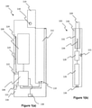
- FIG 1(a) shows a charging device 100.
- the charging device 100 in this example is for an electrically heated smoking system.
- Figure 1(b) shows an electrically heated aerosol-generating device 102.
- the electrically heated aerosol-generating device 102 is adapted to receive a smoking article 104 comprising an aerosol-forming substrate.
- the charging device 100 comprises a rechargeable battery 106, control electronics 108, and electrical contacts 110 configured to provide electrical power to the aerosol-generating device, from the battery 106, when the aerosol-generating device is in connection with the electrical contacts 110.
- the charging device further comprises a temperature sensor 111.
- the rechargeable battery 108 is a lithium cobalt oxide battery.
- the charging device is configured to charge the aerosol-generating device utilising the battery 106, in dependence on the measured temperature.
- the electrical contacts 110 are provided adjacent the bottom of a cavity 112.
- the cavity is configured to receive the aerosol-generating device 102.
- a lid 114 is provided that is configured to secure the aerosol-generating device 102 within the cavity 112 of the charging device 100.
- the components of the charging device 100 are housed within the housing 116.
- the lid 114 is coupled to the housing 116 by hinge 118.
- the charging device 100 is provided with a series of three indicators 120, 122 and 124.
- the indicator 120 is provided to indicate the level of charge remaining in the charging device battery 106.
- the indicator 120 may indicate the percentage of the charge remaining in the charging device battery. For example, 100% would indicate that the battery 106 is fully charged, and 50% would indicate that the battery 106 is half charged. Alternatively the indicator 120 may simply indicated when the charging device battery requires recharging.
- the second indicator 122 is provided to indicate that the aerosol-generating device 102 is fully charged, and ready to be used to generate an aerosol.
- the indicator 122 only indicates this state of readiness once the aerosol-generating device is capable of providing sufficient power to provide the user with a complete smoking experience; for example, sufficient power to aerosolise the entire aerosol forming substrate 104, or sufficient power to generate a predetermined number of puffs.
- the third indicator 124 is provided to indicate the charging regime being used to recharge the battery 106 from the external power supply (not shown). The various charging regimes are described in detail below.
- the aerosol-generating device 102 comprises a rechargeable battery 126, control electronics 128 and electrical contacts 130. As described above, the rechargeable battery 126 of the aerosol-generating device 102 is configured to receive a supply of power from the charging device battery 106 when the electrical contacts 130 are in contact with the electrical contacts 110 of the charging device 100.
- the aerosol-generating device further comprises a temperature sensor 131 for measuring the ambient temperature adjacent the device.
- the rechargeable battery 126 is a lithium iron phosphate battery.
- the aerosol-generating device 102 further comprises a cavity 132 configured to receive the aerosol-generating article 104.
- a heater 134 in the form of, for example, a blade heater, is provided at the bottom of the cavity 132.
- the user activates the aerosol-generating device 102, and power is provided from the battery 126 via the control electronics 128 to the heater 134.
- the heater is heated to a standard operational temperature that is sufficient to generate an aerosol from the aerosol-forming substrate of the aerosol-generating article 104.
- the components of the aerosol-generating device 102 are housed within the housing 136.
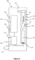
- FIG. 2 shows the aerosol-generating device 102 housed within the cavity of the charging device 100.
- the lid 114 is shown in a closed position. In this closed position the lid is configured to act on the aerosol-generating device 102 such that a good electrical connection is made between the charging device and the aerosol-generating device.
- the electrical contacts 130 of the aerosol-generating device are engaged with the electrical contacts 110 of the charging device.
- the control electronics 108 of the charging device are configured both to control the charging of the charging device battery 106 by the external power supply, and to control the charging of the aerosol-generating device battery 126, in dependence on the ambient temperature.
- the control methods utilised by the control electronics 108 are described with reference to Figures 3 and 4 respectively.
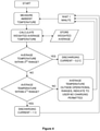
- control electronics 108 determine the appropriate charging current using the following method shown in Figure 3 .
- the ambient temperature adjacent the charging device is measured using temperature sensor 111, and a weighted average of the ambient temperature is calculated.
- the current temperature measurement is given a weighting of 20%, and the previous weighted average is given a weighting of 80%.
- the weighted average is set to the current temperature.
- the control electronics 108 determine whether the weighted average temperature is within a first range of temperatures.
- the first range of temperatures is 0 degrees C to 10 degrees C. If the weighted average temperature is within the range, the control electronics provides a charging current to the battery 106 of less than 0.1 C.
- the control electronics determines whether the weighted average temperature is within a second range of temperatures.
- the second range of temperatures is 10 degrees C to 45 degrees C. If the weighted average temperature is not within the second range of temperatures the battery 106 is without the operational temperature range and no charging is initiated to protect the battery from damage.
- the indicator 124 indicates this to the user.
- control electronics 108 determines whether fast charging is required, if so, a charging current of approximately 1 C is provided, if not a charging current of approximately 0.2 C is provided.
- control electronics 108 determine the appropriate charging current using the following method shown in Figure 4 .
- the ambient temperature adjacent the charging device is measured using temperature sensor 111, and a weighted average of the ambient temperature is calculated.
- the current temperature measurement is given a weighting of 20%, and the previous weighted average is given a weighting of 80%.
- the weighted average is set to the current temperature.
- the control electronics 108 determine whether the weighted average temperature is within a third range of temperatures.
- the third range of temperatures is -10 degrees C to 0 degrees C. If the weighted average temperature is within the range, the control electronics provides a charging current to the battery 126 of approximately 0.2 C.
- the control electronics determines whether the weighted average temperature is within a fourth range of temperatures.
- the second range of temperatures is 0 degrees C to 45 degrees C. If the weighted average temperature is not within the fourth range of temperatures the battery 126 is without the operational temperature range and no charging is initiated to protect the battery from damage. The indicator 124 indicates this to the user.
- control electronics 108 provides a charging current of approximately 1 C to the battery 126.
- the aerosol-generating device control electronics 128 are configured both to control the charging of the device battery 126, and to control the use of the device in dependence on the ambient temperature.
- the control methods utilised by the control electronics 128 are described with reference to Figures 5 and 6 .
- control electronics 128 of the aerosol-generating device are configured to carry out the method shown in Figure 5 to determine whether the battery 126 may be charged.
- the ambient temperature adjacent the device 102 is measured using temperature sensor 131, and a weighted average of the ambient temperature is calculated.
- the current temperature measurement is given a weighting of between 10-50%, and the previous weighted average is given a weighting of 90-50%.
- the weighted average is set to the current temperature.
- the control electronics 128 determine whether the weighted average temperature is within a range of operational temperatures.
- the operational range of temperatures is 0 degrees C to 35 degrees C. If the weighted average temperature is within the range, the control electronics enables a charging current of approximately 10 C to be provided to the battery 126. However, the charging device temperature may change this charging rate in accordance with the control method described above.
- control electronics prevents the battery 126 from being charged to reduce the risk of damaging the battery.
- the ambient temperature adjacent the device 102 is measured using temperature sensor 131, and a weighted average of the ambient temperature is calculated.
- the current temperature measurement is given a weighting of 10-50%, and the previous weighted average is given a weighting of 90-50%.
- the weighted average is set to the current temperature.
- the control electronics 128 determine whether the weighted average temperature is within a range of operational temperatures.
- the operational range of temperatures is 12 degrees C to 65 degrees C. If the weighted average temperature is within the range, the control electronics enables power to be supplied to the heating element 134.
- control electronics 128 prevents power being supplied to the heating element 134.
- the heating element in one specific example has a resistance of approximately 0.7 Ohm at 0 degrees C, and approximately 2 Ohm at 300 degrees C (the temperature at which the heating element is held to generate an aerosol).
- the use of the aerosol-generating device may increase the temperature of the control electronics to above its upper design temperature of 80 degrees C, which could result in unreliable performance.
- the heating element 134 heats to approximately 300 degree C.
- the heating element 134 is in contact with the aerosol-generating substrate of the aerosol-generating article 104. This causes the aerosol-generating substrate to generate an aerosol which can be inhaled by the user when they draw on the aerosol-generating article 104.
Landscapes
- Engineering & Computer Science (AREA)
- Power Engineering (AREA)
- Health & Medical Sciences (AREA)
- Bioinformatics & Cheminformatics (AREA)
- Pulmonology (AREA)
- Anesthesiology (AREA)
- Biomedical Technology (AREA)
- Heart & Thoracic Surgery (AREA)
- Hematology (AREA)
- Life Sciences & Earth Sciences (AREA)
- Animal Behavior & Ethology (AREA)
- General Health & Medical Sciences (AREA)
- Public Health (AREA)
- Veterinary Medicine (AREA)
- Chemical & Material Sciences (AREA)
- Chemical Kinetics & Catalysis (AREA)
- General Chemical & Material Sciences (AREA)
- Charge And Discharge Circuits For Batteries Or The Like (AREA)
- Secondary Cells (AREA)
- Devices For Medical Bathing And Washing (AREA)
- Finger-Pressure Massage (AREA)
- Catching Or Destruction (AREA)
Claims (12)
- Procédé de commande d'un système de génération d'aérosol chauffé électriquement, le système de génération d'aérosol chauffé électriquement comprenant un dispositif de charge primaire (100) comprenant une alimentation électrique rechargeable et un dispositif de génération d'aérosol chauffé électriquement portable configuré pour recevoir un substrat de génération d'aérosol comprenant une alimentation électrique rechargeable et au moins un élément électrique chauffant, le procédé comprenant :le contrôle de la température ambiante adjacente au dispositif de charge primaire (100) ;la détermination d'un courant de charge, pour la charge de l'alimentation électrique rechargeable du dispositif de charge primaire (100), en fonction de la température ambiante ; etla charge de l'alimentation électrique rechargeable du dispositif de charge primaire (100) au courant de charge déterminé,dans lequel :lorsque la température ambiante se situe dans une première plage de températures prédéterminée, le courant de charge est inférieur à environ 0,1 C ;lorsque la température ambiante se situe dans une deuxième plage de températures prédéterminée, le courant de charge est supérieur à environ 0,1 C ; etlorsque la température ambiante est au-dessus d'une température prédéterminée, le fait d'empêcher la charge de l'énergie électrique rechargeable du dispositif de charge (100).
- Procédé selon la revendication 1, comprenant en outre, lorsque l'alimentation électrique rechargeable du dispositif de charge primaire (100) est en cours de charge, l'indication à un utilisateur de quel courant de charge est fournie à l'alimentation électrique.
- Procédé selon la revendication 1, comprenant en outre les étapes de :détermination d'un courant de décharge pour l'alimentation électrique rechargeable du dispositif de charge primaire (100), pour la charge de l'alimentation électrique rechargeable du dispositif de génération d'aérosol chauffé électriquement portable ;charge de l'alimentation électrique rechargeable du dispositif de génération d'aérosol chauffé électriquement portable au courant de décharge déterminé,dans lequel :lorsque la température ambiante se situe dans une troisième plage de températures prédéterminée, le courant de décharge est entre environ 0,1 C et environ 0,3 C ;lorsque la température ambiante se situe dans une quatrième plage de températures prédéterminée, le courant de décharge est entre environ 0,8 C et environ 1,2 C ; etlorsque la température ambiante est au-dessus d'une température prédéterminée, le fait d'empêcher la décharge de l'énergie électrique rechargeable du dispositif de charge primaire (100) .
- Procédé selon la revendication 3, comprenant en outre, lorsque l'alimentation électrique rechargeable du dispositif de charge primaire (100) est déchargée, l'indication à un utilisateur de quel courant de décharge est fournie à l'alimentation électrique du dispositif de génération d'aérosol chauffé électriquement portable.
- Procédé selon l'une quelconque des revendications précédentes, comprenant en outre :le contrôle de la température ambiante adjacente au dispositif de génération d'aérosol chauffé électriquement portable ;la fourniture d'un courant de charge à l'alimentation électrique rechargeable du dispositif de génération d'aérosol chauffé électriquement portable pour recharger l'alimentation électrique, en fonction de la température ambiante, dans lequel :lorsque la température ambiante adjacente au dispositif de génération d'aérosol chauffé électriquement portable se situe dans une plage de températures prédéterminée, la fourniture d'un courant de charge d'environ 10 C vers l'alimentation électrique ; etlorsque la température ambiante adjacente au dispositif de génération d'aérosol chauffé électriquement portable se situe en dehors de la plage de températures prédéterminée, le fait d'empêcher qu'un courant de charge soit fourni à l'alimentation électrique.
- Procédé selon l'une quelconque des revendications précédentes, dans lequel l'étape de contrôle de la température ambiante est réalisée à une fréquence d'environ une fois par minute à environ 5 fois par minute.
- Procédé selon la revendication 6, dans lequel l'étape de détermination d'un courant de charge est réalisée en fonction d'une moyenne pondérée de la température ambiante contrôlée.
- Système de génération d'aérosol chauffé électriquement comprenant :un dispositif de génération d'aérosol chauffé électriquement portable configuré pour recevoir un substrat de génération d'aérosol, le dispositif de génération d'aérosol chauffé électriquement comprenant :un élément de chauffage ;une alimentation électrique rechargeable pour l'alimentation de l'élément de chauffage ;et,un dispositif de charge primaire (100) configuré pour recevoir le dispositif de génération d'aérosol chauffé électriquement portable, le dispositif de charge primaire (100) comprenant :une cavité (112) destinée à recevoir le dispositif de génération d'aérosol chauffé électriquement portable ;une alimentation électrique rechargeable destinée à charger l'alimentation électrique rechargeable du dispositif de génération d'aérosol chauffé électriquement portable ;un détecteur de température (111) destiné à détecter la température ambiante adjacente au dispositif de charge primaire (100) ; etun dispositif de commande destiné à commander l'alimentation électrique du dispositif de charge primaire (100) à partir d'une source d'énergie électrique externe pour recharger l'alimentation électrique, en fonction de la température ambiante adjacente au dispositif de charge primaire (100),dans lequel :lorsque la température ambiante adjacente au dispositif de charge primaire (100) se situe dans une première plage prédéterminée, le dispositif de commande est configuré pour fournir un courant de charge inférieur à environ 0,1 C ;lorsque la température ambiante adjacente au dispositif de charge primaire (100) se situe dans une deuxième plage prédéterminée, le dispositif de commande est configuré pour fournir un courant de charge supérieur à environ 0,1 C ; etlorsque la température ambiante adjacente au dispositif de charge primaire (100) est au-dessus d'une température prédéterminée, le fait d'empêcher la charge de l'énergie électrique rechargeable du dispositif de charge primaire (100).
- Système selon la revendication 8, le dispositif de charge primaire (100) comprenant en outre un indicateur (120, 122, 124) destiné à indiquer à un utilisateur quel courant de charge est fourni à l'alimentation électrique, lorsque l'alimentation électrique rechargeable du dispositif de charge primaire (100) est en cours de charge.
- Système selon la revendication 8 ou 9, dans lequel le dispositif de commande du dispositif de charge primaire (100) est en outre configuré pour commander l'alimentation électrique de l'alimentation électrique du dispositif de charge primaire (100) vers l'alimentation électrique du dispositif de génération d'aérosol chauffé électriquement portable pour recharger l'alimentation électrique ; dans lequel :lorsque la température ambiante adjacente au dispositif de charge primaire (100) se situe dans une troisième plage de températures prédéterminée, le dispositif de commande est configuré pour fournir un courant de décharge entre environ 0,1 C et environ 0,3 C à l'alimentation électrique du dispositif de génération d'aérosol chauffé électriquement portable ;lorsque la température ambiante adjacente au dispositif de charge primaire (100) se situe dans une quatrième plage de températures prédéterminée, le dispositif de commande est configuré pour fournir un courant de décharge entre environ 0,8 C et environ 1,2 C à l'alimentation électrique du dispositif de génération d'aérosol chauffé électriquement portable ; etlorsque la température ambiante adjacente au dispositif de charge primaire (100) est au-dessus d'une température prédéterminée, le dispositif de commande est configuré pour empêcher la décharge de l'énergie électrique rechargeable du dispositif de charge primaire (100).
- Système selon la revendication 10, le dispositif de charge primaire (100) comprenant en outre un indicateur destiné à indiquer à un utilisateur quel courant de décharge est fourni à l'alimentation électrique du dispositif de génération d'aérosol chauffé électriquement portable lorsque l'alimentation électrique rechargeable du dispositif de charge primaire (100) est en cours de décharge.
- Système selon l'une quelconque des revendications 8, 9, 10 ou 11, le dispositif de génération d'aérosol chauffé électriquement portable comprenant en outre un détecteur de température destiné à détecter la température ambiante adjacente au dispositif de génération d'aérosol chauffé électriquement portable, dans lequel le dispositif de commande du dispositif de charge primaire (100) est en outre configuré pour commander l'alimentation électrique de l'alimentation électrique du dispositif de charge primaire (100) vers l'alimentation électrique du dispositif de génération d'aérosol chauffé électriquement portable pour recharger l'alimentation électrique en fonction de la température ambiante adjacente au dispositif de génération d'aérosol chauffé électriquement portable, dans lequel :lorsque la température ambiante adjacente au dispositif de génération d'aérosol chauffé électriquement portable se situe dans une plage de températures prédéterminée, le dispositif de commande est configuré pour fournir un courant de charge d'environ 10 C vers l'alimentation électrique ; etlorsque la température ambiante adjacente au dispositif de génération d'aérosol chauffé électriquement portable se situe en dehors de la plage de températures prédéterminée, le dispositif de commande est configuré pour empêcher qu'un courant de charge soit fourni à l'alimentation électrique.
Priority Applications (7)
| Application Number | Priority Date | Filing Date | Title |
|---|---|---|---|
| EP18162128.5A EP3357358B1 (fr) | 2014-04-30 | 2015-04-24 | Système de génération d'aérosol à chauffage électrique et procédé |
| RS20180485A RS57141B1 (sr) | 2014-04-30 | 2015-04-24 | Sistem za proizvodnju aerosola sa električnim zagrevanjem |
| PL20197000T PL3769635T3 (pl) | 2014-04-30 | 2015-04-24 | Układ wytwarzania aerozolu z grzaniem elektrycznym |
| EP22160927.4A EP4035546A1 (fr) | 2014-04-30 | 2015-04-24 | Système de génération d'aérosol à chauffage électrique |
| EP20197000.1A EP3769635B1 (fr) | 2014-04-30 | 2015-04-24 | Système de génération d'aérosol à chauffage électrique |
| PL15717908.6T PL3136889T5 (pl) | 2014-04-30 | 2015-04-24 | Układ wytwarzania aerozolu z grzaniem elektrycznym |
| SI201530214T SI3136889T1 (en) | 2014-04-30 | 2015-04-24 | Electrically heated aerosol-producing system |
Applications Claiming Priority (2)
| Application Number | Priority Date | Filing Date | Title |
|---|---|---|---|
| EP14166694 | 2014-04-30 | ||
| PCT/EP2015/058909 WO2015165813A1 (fr) | 2014-04-30 | 2015-04-24 | Système de génération d'aérosol chauffé électriquement |
Related Child Applications (5)
| Application Number | Title | Priority Date | Filing Date |
|---|---|---|---|
| EP18162128.5A Division-Into EP3357358B1 (fr) | 2014-04-30 | 2015-04-24 | Système de génération d'aérosol à chauffage électrique et procédé |
| EP18162128.5A Division EP3357358B1 (fr) | 2014-04-30 | 2015-04-24 | Système de génération d'aérosol à chauffage électrique et procédé |
| EP20197000.1A Division-Into EP3769635B1 (fr) | 2014-04-30 | 2015-04-24 | Système de génération d'aérosol à chauffage électrique |
| EP20197000.1A Division EP3769635B1 (fr) | 2014-04-30 | 2015-04-24 | Système de génération d'aérosol à chauffage électrique |
| EP22160927.4A Division EP4035546A1 (fr) | 2014-04-30 | 2015-04-24 | Système de génération d'aérosol à chauffage électrique |
Publications (3)
| Publication Number | Publication Date |
|---|---|
| EP3136889A1 EP3136889A1 (fr) | 2017-03-08 |
| EP3136889B1 EP3136889B1 (fr) | 2018-03-21 |
| EP3136889B2 true EP3136889B2 (fr) | 2022-03-09 |
Family
ID=50639300
Family Applications (4)
| Application Number | Title | Priority Date | Filing Date |
|---|---|---|---|
| EP18162128.5A Active EP3357358B1 (fr) | 2014-04-30 | 2015-04-24 | Système de génération d'aérosol à chauffage électrique et procédé |
| EP22160927.4A Pending EP4035546A1 (fr) | 2014-04-30 | 2015-04-24 | Système de génération d'aérosol à chauffage électrique |
| EP15717908.6A Active EP3136889B2 (fr) | 2014-04-30 | 2015-04-24 | Système de génération d'aérosol à chauffage électrique et procédé |
| EP20197000.1A Active EP3769635B1 (fr) | 2014-04-30 | 2015-04-24 | Système de génération d'aérosol à chauffage électrique |
Family Applications Before (2)
| Application Number | Title | Priority Date | Filing Date |
|---|---|---|---|
| EP18162128.5A Active EP3357358B1 (fr) | 2014-04-30 | 2015-04-24 | Système de génération d'aérosol à chauffage électrique et procédé |
| EP22160927.4A Pending EP4035546A1 (fr) | 2014-04-30 | 2015-04-24 | Système de génération d'aérosol à chauffage électrique |
Family Applications After (1)
| Application Number | Title | Priority Date | Filing Date |
|---|---|---|---|
| EP20197000.1A Active EP3769635B1 (fr) | 2014-04-30 | 2015-04-24 | Système de génération d'aérosol à chauffage électrique |
Country Status (29)
| Country | Link |
|---|---|
| US (4) | US10333330B2 (fr) |
| EP (4) | EP3357358B1 (fr) |
| JP (3) | JP6643245B2 (fr) |
| KR (2) | KR102472386B1 (fr) |
| CN (4) | CN106132222A (fr) |
| AR (1) | AR100228A1 (fr) |
| AU (1) | AU2015252164B2 (fr) |
| BR (1) | BR112016023120B1 (fr) |
| CA (1) | CA2937281A1 (fr) |
| DK (1) | DK3136889T3 (fr) |
| ES (3) | ES2828353T3 (fr) |
| HK (1) | HK1258719A1 (fr) |
| HU (3) | HUE051169T2 (fr) |
| IL (1) | IL246535B (fr) |
| LT (1) | LT3136889T (fr) |
| MX (1) | MX2016014079A (fr) |
| MY (1) | MY188106A (fr) |
| NO (1) | NO3136889T3 (fr) |
| PH (1) | PH12016501299A1 (fr) |
| PL (2) | PL3769635T3 (fr) |
| PT (1) | PT3136889T (fr) |
| RS (1) | RS57141B1 (fr) |
| RU (1) | RU2676256C2 (fr) |
| SG (1) | SG11201605888QA (fr) |
| SI (1) | SI3136889T1 (fr) |
| TW (1) | TWI681691B (fr) |
| UA (1) | UA118782C2 (fr) |
| WO (1) | WO2015165813A1 (fr) |
| ZA (1) | ZA201604456B (fr) |
Families Citing this family (103)
| Publication number | Priority date | Publication date | Assignee | Title |
|---|---|---|---|---|
| US10244793B2 (en) | 2005-07-19 | 2019-04-02 | Juul Labs, Inc. | Devices for vaporization of a substance |
| US10279934B2 (en) | 2013-03-15 | 2019-05-07 | Juul Labs, Inc. | Fillable vaporizer cartridge and method of filling |
| WO2015023996A2 (fr) | 2013-08-15 | 2015-02-19 | Loec, Inc. | Procédé, système et dispositif destinés à la détection et à la charge sans commutateur |
| US10039321B2 (en) | 2013-11-12 | 2018-08-07 | Vmr Products Llc | Vaporizer |
| USD825102S1 (en) | 2016-07-28 | 2018-08-07 | Juul Labs, Inc. | Vaporizer device with cartridge |
| USD842536S1 (en) | 2016-07-28 | 2019-03-05 | Juul Labs, Inc. | Vaporizer cartridge |
| US10058129B2 (en) | 2013-12-23 | 2018-08-28 | Juul Labs, Inc. | Vaporization device systems and methods |
| HRP20211514T1 (hr) | 2013-12-23 | 2021-12-24 | Juul Labs International Inc. | Sustavi uređaja za isparavanje |
| US20160366947A1 (en) | 2013-12-23 | 2016-12-22 | James Monsees | Vaporizer apparatus |
| US10159282B2 (en) | 2013-12-23 | 2018-12-25 | Juul Labs, Inc. | Cartridge for use with a vaporizer device |
| US10076139B2 (en) | 2013-12-23 | 2018-09-18 | Juul Labs, Inc. | Vaporizer apparatus |
| EP3171720B1 (fr) | 2014-07-24 | 2018-10-24 | Nicoventures Holdings Limited | Boîtier de recharge pour une cigarette électronique |
| TWI681691B (zh) * | 2014-04-30 | 2020-01-01 | 瑞士商菲利浦莫里斯製品股份有限公司 | 電熱式氣溶膠產生系統、裝置及其控制方法 |
| US9985455B2 (en) | 2014-05-13 | 2018-05-29 | Fontem Holdings 4 B.V. | Characterization and intelligent charging of electronic cigarettes |
| GB2528711B (en) | 2014-07-29 | 2019-02-20 | Nicoventures Holdings Ltd | E-cigarette and re-charging pack |
| MX361471B (es) * | 2014-10-17 | 2018-12-05 | Philip Morris Products Sa | Sistema y método para configurar contactos eléctricos en un dispositivo eléctrico. |
| JP6802792B2 (ja) | 2014-12-05 | 2020-12-23 | ジュール・ラブズ・インコーポレイテッドJuul Labs, Inc. | 調整された投与量の制御 |
| WO2017139595A1 (fr) | 2016-02-11 | 2017-08-17 | Pax Labs, Inc. | Cartouche de vaporisateur remplissable et procédé de remplissage |
| SG10202108578XA (en) | 2016-02-11 | 2021-09-29 | Juul Labs Inc | Securely attaching cartridges for vaporizer devices |
| US10405582B2 (en) | 2016-03-10 | 2019-09-10 | Pax Labs, Inc. | Vaporization device with lip sensing |
| US10645972B2 (en) | 2016-04-22 | 2020-05-12 | Altria Client Services Llc | Aerosol-generating device comprising semiconductor heaters |
| RU2727102C2 (ru) * | 2016-04-22 | 2020-07-17 | Филип Моррис Продактс С.А. | Генерирующее аэрозоль устройство, содержащее полупроводниковые нагреватели |
| USD849996S1 (en) | 2016-06-16 | 2019-05-28 | Pax Labs, Inc. | Vaporizer cartridge |
| USD836541S1 (en) | 2016-06-23 | 2018-12-25 | Pax Labs, Inc. | Charging device |
| USD851830S1 (en) | 2016-06-23 | 2019-06-18 | Pax Labs, Inc. | Combined vaporizer tamp and pick tool |
| TW201800020A (zh) * | 2016-06-29 | 2018-01-01 | 菲利浦莫里斯製品股份有限公司 | 具有可充電電源供應器之電操作式氣溶膠產生系統 |
| RU2736025C2 (ru) * | 2016-06-29 | 2020-11-11 | Филип Моррис Продактс С.А. | Питаемое от батареи генерирующее аэрозоль устройство, содержащее средства предварительного нагрева батареи в зависимости от температуры |
| CA3047236C (fr) | 2016-12-16 | 2023-01-03 | Kt&G Corporation | Procede et appareil de generation d'aerosol |
| CN108244705B (zh) * | 2016-12-29 | 2024-05-24 | 上海烟草集团有限责任公司 | 加热不燃烧烟具 |
| EP3566280B1 (fr) * | 2017-01-03 | 2021-08-11 | Philip Morris Products S.A. | Station de chargement d'un dispositif de production d'aérosol chauffé électriquement pour voiture |
| KR101987235B1 (ko) * | 2017-01-18 | 2019-09-30 | 주식회사 케이티앤지 | 전기 가열식 흡연기의 히터 |
| KR102183092B1 (ko) * | 2017-01-18 | 2020-11-25 | 주식회사 케이티앤지 | 전력 효율이 개선된 미세 입자 발생 장치 |
| KR102199792B1 (ko) * | 2017-01-18 | 2021-01-07 | 주식회사 케이티앤지 | 가열 방식의 미세 입자 발생 장치 |
| CN114711472A (zh) * | 2017-01-18 | 2022-07-08 | 韩国烟草人参公社 | 气溶胶生成装置、其控制方法及包括该装置的充电系统 |
| KR102185910B1 (ko) * | 2017-01-18 | 2020-12-03 | 주식회사 케이티앤지 | 사용 정보를 출력해주는 미세 입자 발생 장치 |
| EP3571941B1 (fr) * | 2017-01-18 | 2022-10-26 | KT & G Corporation | Dispositif de génération de particules fines |
| KR102316497B1 (ko) * | 2017-01-18 | 2021-10-25 | 주식회사 케이티앤지 | 에어로졸 생성 장치 및 이의 제어 방법 |
| KR102185911B1 (ko) * | 2017-01-18 | 2020-12-03 | 주식회사 케이티앤지 | 에어로졸 생성 장치의 충전 시스템 |
| WO2018135887A1 (fr) * | 2017-01-18 | 2018-07-26 | 주식회사 케이티앤지 | Dispositif de génération de particules fines |
| WO2018135888A1 (fr) * | 2017-01-18 | 2018-07-26 | 주식회사 케이티앤지 | Dispositif de génération d'aérosol, son procédé de commande, et système de charge le comprenant |
| CN110475488B (zh) * | 2017-03-30 | 2022-07-26 | 韩国烟草人参公社 | 气溶胶生成装置及可容纳该气溶胶生成装置的托架 |
| US20210106051A1 (en) * | 2017-03-30 | 2021-04-15 | Kt&G Corporation | Aerosol generating apparatus and cradle capable of receiving same |
| KR102246245B1 (ko) * | 2017-03-30 | 2021-04-29 | 주식회사 케이티앤지 | 에어로졸 생성 장치 및 이를 수용할 수 있는 크래들 |
| US11252999B2 (en) | 2017-04-11 | 2022-02-22 | Kt&G Corporation | Aerosol generating device |
| US11771138B2 (en) | 2017-04-11 | 2023-10-03 | Kt&G Corporation | Aerosol generating device and method for providing smoking restriction function in aerosol generating device |
| US11622582B2 (en) | 2017-04-11 | 2023-04-11 | Kt&G Corporation | Aerosol generating device and method for providing adaptive feedback through puff recognition |
| CN115708600A (zh) | 2017-04-11 | 2023-02-24 | 韩国烟草人参公社 | 气溶胶生成装置 |
| US20210127748A1 (en) | 2017-04-11 | 2021-05-06 | Kt&G Corporation | Aerosol generating device and method for providing adaptive feedback through puff recognition |
| RU2757088C2 (ru) * | 2017-04-11 | 2021-10-11 | Филип Моррис Продактс С.А. | Генерирующее аэрозоль устройство |
| JP6854361B2 (ja) | 2017-04-11 | 2021-04-07 | ケーティー・アンド・ジー・コーポレーション | 喫煙部材クリーニングデバイス及び喫煙部材システム |
| CN110494053B (zh) | 2017-04-11 | 2022-05-31 | 韩国烟草人参公社 | 气溶胶生成装置 |
| US11596179B2 (en) | 2017-04-11 | 2023-03-07 | Altria Client Services Llc | Aerosol-generating devices |
| KR102146053B1 (ko) * | 2017-05-11 | 2020-08-20 | 주식회사 케이티앤지 | 에어로졸 생성 장치의 충전 시스템 |
| US11337464B2 (en) | 2017-05-26 | 2022-05-24 | Kt&G Corporation | System for charging aerosol generation device |
| KR102035313B1 (ko) | 2017-05-26 | 2019-10-22 | 주식회사 케이티앤지 | 히터 조립체 및 이를 구비한 에어로졸 생성 장치 |
| WO2018217030A1 (fr) * | 2017-05-26 | 2018-11-29 | 주식회사 케이티앤지 | Système de charge de dispositif de génération d'aérosol |
| WO2018230002A1 (fr) * | 2017-06-16 | 2018-12-20 | 株式会社 東亜産業 | Procédé de fabrication d'un matériau de remplissage pour cartouche de cigarette électronique dans laquelle une plante autre que le tabac est utilisée, et matériau de remplissage pour cartouche de cigarette électronique dans laquelle une plante autre que le tabac est utilisée |
| WO2019031877A2 (fr) | 2017-08-09 | 2019-02-14 | 주식회사 케이티앤지 | Dispositif de génération d'aérosol et procédé de régulation pour dispositif de génération d'aérosol |
| US11849762B2 (en) | 2017-08-09 | 2023-12-26 | Kt&G Corporation | Electronic cigarette control method and device |
| EP3679813A4 (fr) | 2017-09-06 | 2021-07-14 | KT&G Corporation | Dispositif de production d'aérosol |
| CN111904043A (zh) * | 2017-09-06 | 2020-11-10 | 韩国烟草人参公社 | 气溶胶生成装置 |
| USD887632S1 (en) | 2017-09-14 | 2020-06-16 | Pax Labs, Inc. | Vaporizer cartridge |
| US10505383B2 (en) * | 2017-09-19 | 2019-12-10 | Rai Strategic Holdings, Inc. | Intelligent charger for an aerosol delivery device |
| WO2019105812A1 (fr) * | 2017-11-30 | 2019-06-06 | Philip Morris Products S.A. | Systèmes de génération d'un aérosol liquide |
| CN207803449U (zh) * | 2018-01-16 | 2018-09-04 | 东莞市国研电热材料有限公司 | 一种电子烟用圆棒状陶瓷发热体 |
| JP7203112B2 (ja) * | 2018-01-19 | 2023-01-12 | ヴェンタス メディカル リミテッド | 方法、吸入デバイス及びコンピュータ・プログラム |
| WO2019186668A1 (fr) * | 2018-03-26 | 2019-10-03 | 日本たばこ産業株式会社 | Dispositif de génération d'aérosol, procédé de commande et programme |
| WO2019219867A1 (fr) | 2018-05-17 | 2019-11-21 | Philip Morris Products S.A. | Dispositif de génération d'aérosol à bobine d'induction améliorée |
| JP6871483B2 (ja) | 2018-05-31 | 2021-05-12 | 日本たばこ産業株式会社 | 香味生成装置、香味生成装置を制御する方法、及びプログラム |
| EP3884790A1 (fr) | 2018-05-31 | 2021-09-29 | Japan Tobacco Inc. | Dispositif générateur d'arôme |
| EP3813573A1 (fr) * | 2018-06-28 | 2021-05-05 | JT International S.A. | Dispositif à fumer électronique, distributeur, système à fumer et procédé de distribution d'une formulation de mousse de tabac |
| JP7497304B2 (ja) * | 2018-07-10 | 2024-06-10 | フィリップ・モーリス・プロダクツ・ソシエテ・アノニム | 空気質センサーを備えたエアロゾル生成システム |
| US10897925B2 (en) | 2018-07-27 | 2021-01-26 | Joseph Pandolfino | Articles and formulations for smoking products and vaporizers |
| US20200035118A1 (en) | 2018-07-27 | 2020-01-30 | Joseph Pandolfino | Methods and products to facilitate smokers switching to a tobacco heating product or e-cigarettes |
| WO2020035899A1 (fr) | 2018-08-13 | 2020-02-20 | 日本たばこ産業株式会社 | Système, procédé et programme de génération de d'arôme |
| JP6577113B1 (ja) | 2018-10-03 | 2019-09-18 | 日本たばこ産業株式会社 | エアロゾル生成装置、エアロゾル生成装置用の制御ユニット、方法及びプログラム |
| JP2020058236A (ja) | 2018-10-04 | 2020-04-16 | 日本たばこ産業株式会社 | 吸引成分生成装置、制御回路、吸引成分生成装置の制御方法および制御プログラム |
| WO2020092245A1 (fr) * | 2018-10-29 | 2020-05-07 | Zorday IP, LLC | Cigarette électronique compatible avec un réseau |
| JP6557393B1 (ja) * | 2018-10-31 | 2019-08-07 | 日本たばこ産業株式会社 | エアロゾル吸引器用の電源ユニットと、その制御方法及び制御プログラム |
| JP6573737B1 (ja) | 2019-01-17 | 2019-09-11 | 日本たばこ産業株式会社 | エアロゾル吸引器用の電源ユニット |
| GB201900827D0 (en) * | 2019-01-21 | 2019-03-13 | British American Tobacco Investments Ltd | Tobacco industy product and methods relating to tobacco industry products |
| EP3941248A1 (fr) * | 2019-03-22 | 2022-01-26 | Philip Morris Products S.A. | Boîtier doté d'un support rotatif pour un dispositif de génération d'aérosol |
| JP6639720B1 (ja) * | 2019-04-09 | 2020-02-05 | 日本たばこ産業株式会社 | 吸引装置に具備される電源ユニット、吸引装置、及び電源ユニットを動作させる方法 |
| KR102275791B1 (ko) * | 2019-08-16 | 2021-07-09 | 주식회사 케이티앤지 | 에어로졸 생성 물품, 에어로졸 생성 장치 및 에어로졸 생성 시스템 |
| JP7308174B2 (ja) * | 2019-08-20 | 2023-07-13 | 日本たばこ産業株式会社 | エアロゾル生成装置、エアロゾル生成装置用の制御ユニット、方法及びプログラム |
| KR20210039199A (ko) | 2019-10-01 | 2021-04-09 | 주식회사 케이티앤지 | 디스플레이를 포함하는 에어로졸 생성 장치 |
| KR102330809B1 (ko) * | 2019-10-17 | 2021-11-24 | 주식회사 케이티앤지 | 에어로졸 생성 장치 및 그의 예열 방법 |
| GB201917444D0 (en) * | 2019-11-29 | 2020-01-15 | Nicoventures Trading Ltd | Aerosol provision device |
| KR102397451B1 (ko) | 2020-01-06 | 2022-05-12 | 주식회사 케이티앤지 | 에어로졸 생성 장치 |
| KR102323511B1 (ko) | 2020-02-05 | 2021-11-08 | 주식회사 케이티앤지 | 에어로졸 생성 장치 및 그의 동작 방법 |
| EP3937337B1 (fr) | 2020-07-09 | 2022-11-09 | Japan Tobacco Inc. | Unité d'alimentation électrique pour inhalateur d'aérosol comprenant un capteur de température |
| JP6864769B1 (ja) | 2020-07-09 | 2021-04-28 | 日本たばこ産業株式会社 | エアロゾル吸引器の電源ユニット |
| JP6856810B1 (ja) * | 2020-09-07 | 2021-04-14 | 日本たばこ産業株式会社 | エアロゾル生成装置の電源ユニット |
| JP6856811B1 (ja) | 2020-09-07 | 2021-04-14 | 日本たばこ産業株式会社 | エアロゾル生成装置の電源ユニット |
| JP6905134B1 (ja) | 2020-09-07 | 2021-07-21 | 日本たばこ産業株式会社 | エアロゾル生成装置の電源ユニット |
| WO2022241643A1 (fr) * | 2021-05-18 | 2022-11-24 | 深圳麦克韦尔科技有限公司 | Circuit d'entraînement pour appareil d'atomisation électronique, et appareil d'atomisation électronique |
| KR102545834B1 (ko) * | 2021-06-25 | 2023-06-20 | 주식회사 케이티앤지 | 카트리지 및 이를 포함하는 에어로졸 생성 장치 |
| KR20230085770A (ko) * | 2021-12-07 | 2023-06-14 | 주식회사 케이티앤지 | 에어로졸 생성장치 및 그 동작방법 |
| WO2023118786A1 (fr) * | 2021-12-21 | 2023-06-29 | Nicoventures Trading Limited | Système de fourniture d'aérosol |
| KR20230103461A (ko) * | 2021-12-31 | 2023-07-07 | 주식회사 케이티앤지 | 에어로졸 생성장치 |
| CN114271554B (zh) * | 2022-01-04 | 2024-07-12 | 上海烟草集团有限责任公司 | 一种气溶胶生成系统及其控制方法 |
| WO2024171268A1 (fr) * | 2023-02-13 | 2024-08-22 | 日本たばこ産業株式会社 | Unité d'alimentation électrique pour dispositif de génération d'aérosol et procédé de commande |
| WO2024172280A1 (fr) * | 2023-02-15 | 2024-08-22 | 주식회사 케이티앤지 | Dispositif de génération d'aérosol et son procédé de commande |
Family Cites Families (59)
| Publication number | Priority date | Publication date | Assignee | Title |
|---|---|---|---|---|
| US4291838A (en) | 1979-12-26 | 1981-09-29 | C. R. Bard, Inc. | Nebulizer and associated heater |
| JP3096319B2 (ja) | 1990-07-13 | 2000-10-10 | 日立工機株式会社 | 急速充電器 |
| US5192919A (en) | 1991-10-03 | 1993-03-09 | Motorola, Inc. | Transmitter having a temperature adjusted power amplifier |
| US5712795A (en) | 1995-10-02 | 1998-01-27 | Alaris Medical Systems, Inc. | Power management system |
| US5934289A (en) * | 1996-10-22 | 1999-08-10 | Philip Morris Incorporated | Electronic smoking system |
| US6694975B2 (en) | 1996-11-21 | 2004-02-24 | Aradigm Corporation | Temperature controlling device for aerosol drug delivery |
| US6142146A (en) | 1998-06-12 | 2000-11-07 | Microdose Technologies, Inc. | Inhalation device |
| JP3563965B2 (ja) * | 1998-06-29 | 2004-09-08 | 本田技研工業株式会社 | バッテリ充電装置 |
| JP2001251780A (ja) * | 2000-03-07 | 2001-09-14 | Sharp Corp | 二次電池の充電装置 |
| US6803545B2 (en) | 2002-06-05 | 2004-10-12 | Philip Morris Incorporated | Electrically heated smoking system and methods for supplying electrical power from a lithium ion power source |
| US7166987B2 (en) | 2003-10-10 | 2007-01-23 | R. F. Tech Co., Ltd | Portable charger for mobile phone |
| US7206567B2 (en) | 2003-11-10 | 2007-04-17 | Research In Motion Limited | Methods and apparatus for limiting communication capabilities in mobile communication devices |
| JP4251117B2 (ja) * | 2004-07-02 | 2009-04-08 | 日本電気株式会社 | 携帯通信端末及びその発熱対策方法 |
| JP4101218B2 (ja) | 2004-08-31 | 2008-06-18 | 三洋電機株式会社 | 充電器 |
| JP2006115654A (ja) | 2004-10-18 | 2006-04-27 | Nec Corp | 充電制御回路、充電制御方法、及び該充電制御回路が設けられた電子機器 |
| KR100630929B1 (ko) | 2004-12-03 | 2006-10-02 | 삼성전자주식회사 | 전자기기 시스템 및 전자기기 시스템의 제어방법 |
| JP4796674B2 (ja) | 2005-06-24 | 2011-10-19 | 日立ビアメカニクス株式会社 | スキャナ |
| JP2007006628A (ja) * | 2005-06-24 | 2007-01-11 | Matsushita Electric Works Ltd | 充電器およびそれを用いる電動工具セット |
| US7186958B1 (en) | 2005-09-01 | 2007-03-06 | Zhao Wei, Llc | Inhaler |
| US8264203B2 (en) * | 2006-03-31 | 2012-09-11 | Valence Technology, Inc. | Monitoring state of charge of a battery |
| KR100820679B1 (ko) * | 2007-06-29 | 2008-04-11 | 경북대학교 산학협력단 | 차량용 휴대 단말기의 전원장치 |
| KR100929036B1 (ko) | 2007-09-27 | 2009-11-30 | 삼성에스디아이 주식회사 | 배터리 팩의 보호회로, 이를 구비하는 배터리 팩 및 이의동작방법 |
| EP2213321B1 (fr) | 2007-11-29 | 2014-07-23 | Japan Tobacco Inc. | Système d'inhalation d'aérosol |
| EP2100525A1 (fr) | 2008-03-14 | 2009-09-16 | Philip Morris Products S.A. | Système de génération d'aérosol à chauffage électrique et procédé |
| US20090251108A1 (en) | 2008-04-03 | 2009-10-08 | Chun-Chen Chao | Portable electronic device and method of adjusting charging current for a rechargeable battery unit thereof |
| US20090283103A1 (en) | 2008-05-13 | 2009-11-19 | Nielsen Michael D | Electronic vaporizing devices and docking stations |
| JP4829999B2 (ja) * | 2009-05-08 | 2011-12-07 | パナソニック株式会社 | 電源装置及び電池パック |
| CN101634469B (zh) * | 2009-09-01 | 2012-11-14 | 东莞天龙阿克达电子有限公司 | 一种便携式取暖器 |
| ES2392917T3 (es) | 2009-12-22 | 2012-12-17 | Ctek Sweden Ab | Un sistema para cargar batería, un sistema operado con batería y un método para la carga controlada por estado |
| CN201549917U (zh) * | 2010-03-01 | 2010-08-11 | 北京地铁车辆装备有限公司 | 蓄电池组件 |
| CA3047478C (fr) * | 2010-04-30 | 2022-06-14 | Fontem Holdings 4 B.V. | Dispositif electronique pour fumer avec controle du dosage |
| CN101826744B (zh) * | 2010-05-05 | 2012-06-06 | 深圳爱商精密电子有限公司 | 铁电池充电电路 |
| US8334675B2 (en) * | 2010-07-28 | 2012-12-18 | Honda Motor Co., Ltd. | Method of charging battery based on calcualtion of an ion concentration of a solid active material and battery charging control system |
| EP2454956A1 (fr) * | 2010-11-19 | 2012-05-23 | Philip Morris Products S.A. | Système de fumage chauffé électriquement comportant au moins deux unités |
| CN103222147B (zh) * | 2010-11-25 | 2017-04-19 | 诺基亚技术有限公司 | 情境感知电池充电 |
| JP5732930B2 (ja) * | 2011-03-11 | 2015-06-10 | 日産自動車株式会社 | バッテリ充電制御装置 |
| JP5736860B2 (ja) * | 2011-03-11 | 2015-06-17 | 日産自動車株式会社 | バッテリ充電制御装置 |
| JP5760531B2 (ja) * | 2011-03-11 | 2015-08-12 | 日産自動車株式会社 | バッテリ温度制御装置 |
| CA2842119C (fr) | 2011-07-18 | 2015-07-07 | Dog Microsystems Inc. | Procede et systeme pour effectuer un rendu au moyen d'un modele de projection en deux parties |
| WO2013034454A1 (fr) * | 2011-09-06 | 2013-03-14 | British American Tobacco (Investments) Limited | Chauffage d'un matériau fumable |
| JP5794104B2 (ja) * | 2011-10-27 | 2015-10-14 | ソニー株式会社 | 電池パック、蓄電システム、電子機器、電動車両および電力システム |
| MY168133A (en) * | 2011-12-30 | 2018-10-11 | Philip Morris Products Sa | Aerosol-generating device with air flow detection |
| US10448670B2 (en) * | 2011-12-30 | 2019-10-22 | Philip Morris Products S.A. | Aerosol generating system with consumption monitoring and feedback |
| MY168388A (en) * | 2012-01-03 | 2018-10-31 | Philip Morris Products Sa | Power supply system for portable aerosol-generating device |
| TWI464997B (zh) | 2012-05-02 | 2014-12-11 | Wistron Corp | 電池充電電路 |
| US9155336B2 (en) | 2012-06-16 | 2015-10-13 | Huizhou Kimree Technology Co., Ltd., Shenzhen Branch | Electronic cigarette and electronic cigarette device |
| WO2013185358A1 (fr) | 2012-06-16 | 2013-12-19 | Liu Qiuming | Boîtier de cigarette électronique et dispositif de cigarette électronique associé |
| EP2701268A1 (fr) * | 2012-08-24 | 2014-02-26 | Philip Morris Products S.A. | Système électronique portable comprenant un dispositif de charge et procédé de chargement d'une batterie secondaire |
| TWI595340B (zh) * | 2012-09-11 | 2017-08-11 | 菲利浦莫里斯製品股份有限公司 | 控制電加熱元件之方法及裝置、氣溶膠產生系統、在電操作氣溶膠產生裝置之可程式電路上執行以實施該控制電加熱元件之方法的電腦程式、及儲存該電腦程式的電腦可讀取儲存媒體 |
| WO2014047953A1 (fr) | 2012-09-29 | 2014-04-03 | Wu Changming | Dispositif électronique pour fumeur |
| GB2507102B (en) | 2012-10-19 | 2015-12-30 | Nicoventures Holdings Ltd | Electronic inhalation device |
| CN203166473U (zh) | 2013-03-20 | 2013-08-28 | 向智勇 | 电子烟或烟弹的过热保护装置 |
| JP2014222868A (ja) * | 2013-05-14 | 2014-11-27 | 富士通株式会社 | デバイス制御装置、デバイス制御方法、およびデバイス制御システム |
| CN203986093U (zh) * | 2013-09-13 | 2014-12-10 | 惠州市吉瑞科技有限公司 | 一种电子烟的电池组件、雾化组件以及电子烟 |
| KR101854218B1 (ko) * | 2013-10-22 | 2018-05-03 | 삼성에스디아이 주식회사 | 배터리 팩, 배터리 팩을 포함하는 에너지 저장 시스템, 배터리 팩의 충전 방법 |
| HRP20211514T1 (hr) * | 2013-12-23 | 2021-12-24 | Juul Labs International Inc. | Sustavi uređaja za isparavanje |
| KR102502317B1 (ko) * | 2014-04-30 | 2023-02-23 | 필립모리스 프로덕츠 에스.에이. | 배터리 표시가 있는 에어로졸 발생 장치 |
| TWI681691B (zh) * | 2014-04-30 | 2020-01-01 | 瑞士商菲利浦莫里斯製品股份有限公司 | 電熱式氣溶膠產生系統、裝置及其控制方法 |
| SI3282871T1 (sl) * | 2015-04-15 | 2019-08-30 | Philip Morris Products S.A. | Naprava in postopek za krmiljenje električnega grelca za omejitev temperature glede na želeni temperaturni profil v času |
-
2015
- 2015-04-23 TW TW104112979A patent/TWI681691B/zh not_active IP Right Cessation
- 2015-04-24 SG SG11201605888QA patent/SG11201605888QA/en unknown
- 2015-04-24 CN CN201580013587.2A patent/CN106132222A/zh active Pending
- 2015-04-24 KR KR1020167025472A patent/KR102472386B1/ko active IP Right Grant
- 2015-04-24 IL IL246535A patent/IL246535B/en unknown
- 2015-04-24 PT PT157179086T patent/PT3136889T/pt unknown
- 2015-04-24 BR BR112016023120-1A patent/BR112016023120B1/pt active IP Right Grant
- 2015-04-24 EP EP18162128.5A patent/EP3357358B1/fr active Active
- 2015-04-24 ES ES18162128T patent/ES2828353T3/es active Active
- 2015-04-24 EP EP22160927.4A patent/EP4035546A1/fr active Pending
- 2015-04-24 PL PL20197000T patent/PL3769635T3/pl unknown
- 2015-04-24 CA CA2937281A patent/CA2937281A1/fr not_active Abandoned
- 2015-04-24 CN CN202310443229.1A patent/CN116491721A/zh active Pending
- 2015-04-24 US US15/303,439 patent/US10333330B2/en active Active
- 2015-04-24 EP EP15717908.6A patent/EP3136889B2/fr active Active
- 2015-04-24 UA UAA201609382A patent/UA118782C2/uk unknown
- 2015-04-24 PL PL15717908.6T patent/PL3136889T5/pl unknown
- 2015-04-24 RS RS20180485A patent/RS57141B1/sr unknown
- 2015-04-24 CN CN202310436702.3A patent/CN116491720A/zh active Pending
- 2015-04-24 CN CN202310437966.0A patent/CN116473310A/zh active Pending
- 2015-04-24 HU HUE18162128A patent/HUE051169T2/hu unknown
- 2015-04-24 MY MYPI2016702605A patent/MY188106A/en unknown
- 2015-04-24 SI SI201530214T patent/SI3136889T1/en unknown
- 2015-04-24 DK DK15717908.6T patent/DK3136889T3/en active
- 2015-04-24 ES ES20197000T patent/ES2911081T3/es active Active
- 2015-04-24 EP EP20197000.1A patent/EP3769635B1/fr active Active
- 2015-04-24 ES ES15717908.6T patent/ES2666428T3/es active Active
- 2015-04-24 NO NO15717908A patent/NO3136889T3/no unknown
- 2015-04-24 KR KR1020227041430A patent/KR102698286B1/ko active IP Right Grant
- 2015-04-24 HU HUE15717908A patent/HUE036978T2/hu unknown
- 2015-04-24 HU HUE20197000A patent/HUE058042T2/hu unknown
- 2015-04-24 WO PCT/EP2015/058909 patent/WO2015165813A1/fr active Application Filing
- 2015-04-24 AU AU2015252164A patent/AU2015252164B2/en not_active Ceased
- 2015-04-24 MX MX2016014079A patent/MX2016014079A/es unknown
- 2015-04-24 LT LTEP15717908.6T patent/LT3136889T/lt unknown
- 2015-04-24 JP JP2016556311A patent/JP6643245B2/ja active Active
- 2015-04-24 RU RU2016146694A patent/RU2676256C2/ru active
- 2015-04-29 AR ARP150101294A patent/AR100228A1/es active IP Right Grant
-
2016
- 2016-06-30 PH PH12016501299A patent/PH12016501299A1/en unknown
- 2016-06-30 ZA ZA2016/04456A patent/ZA201604456B/en unknown
-
2019
- 2019-01-22 HK HK19101120.0A patent/HK1258719A1/zh unknown
- 2019-04-04 US US16/375,268 patent/US10483781B2/en active Active
- 2019-09-11 US US16/568,062 patent/US11083225B2/en active Active
-
2020
- 2020-01-06 JP JP2020000193A patent/JP7234152B2/ja active Active
-
2021
- 2021-07-07 US US17/369,234 patent/US20210329974A1/en active Pending
-
2023
- 2023-02-22 JP JP2023026389A patent/JP2023054267A/ja active Pending
Also Published As
Similar Documents
| Publication | Publication Date | Title |
|---|---|---|
| US10483781B2 (en) | Electrically heated aerosol-generating system | |
| EP3092909B1 (fr) | Système d'alimentation électrique pour dispositif de production d'aérosol portatif | |
| RU2780825C2 (ru) | Электрически нагреваемая система, генерирующая аэрозоль | |
| KR20240132381A (ko) | 전기 가열식 에어로졸 발생 시스템 |
Legal Events
| Date | Code | Title | Description |
|---|---|---|---|
| STAA | Information on the status of an ep patent application or granted ep patent |
Free format text: STATUS: THE INTERNATIONAL PUBLICATION HAS BEEN MADE |
|
| PUAI | Public reference made under article 153(3) epc to a published international application that has entered the european phase |
Free format text: ORIGINAL CODE: 0009012 |
|
| STAA | Information on the status of an ep patent application or granted ep patent |
Free format text: STATUS: REQUEST FOR EXAMINATION WAS MADE |
|
| 17P | Request for examination filed |
Effective date: 20161020 |
|
| AK | Designated contracting states |
Kind code of ref document: A1 Designated state(s): AL AT BE BG CH CY CZ DE DK EE ES FI FR GB GR HR HU IE IS IT LI LT LU LV MC MK MT NL NO PL PT RO RS SE SI SK SM TR |
|
| AX | Request for extension of the european patent |
Extension state: BA ME |
|
| DAV | Request for validation of the european patent (deleted) | ||
| DAX | Request for extension of the european patent (deleted) | ||
| REG | Reference to a national code |
Ref country code: DE Ref legal event code: R079 Ref document number: 602015009114 Country of ref document: DE Free format text: PREVIOUS MAIN CLASS: A24F0047000000 Ipc: H02J0007000000 |
|
| GRAP | Despatch of communication of intention to grant a patent |
Free format text: ORIGINAL CODE: EPIDOSNIGR1 |
|
| STAA | Information on the status of an ep patent application or granted ep patent |
Free format text: STATUS: GRANT OF PATENT IS INTENDED |
|
| RIC1 | Information provided on ipc code assigned before grant |
Ipc: H02J 7/00 20060101AFI20170905BHEP Ipc: A24F 47/00 20060101ALI20170905BHEP Ipc: H05B 1/02 20060101ALI20170905BHEP |
|
| INTG | Intention to grant announced |
Effective date: 20171005 |
|
| REG | Reference to a national code |
Ref country code: HK Ref legal event code: DE Ref document number: 1228692 Country of ref document: HK |
|
| GRAS | Grant fee paid |
Free format text: ORIGINAL CODE: EPIDOSNIGR3 |
|
| GRAA | (expected) grant |
Free format text: ORIGINAL CODE: 0009210 |
|
| STAA | Information on the status of an ep patent application or granted ep patent |
Free format text: STATUS: THE PATENT HAS BEEN GRANTED |
|
| AK | Designated contracting states |
Kind code of ref document: B1 Designated state(s): AL AT BE BG CH CY CZ DE DK EE ES FI FR GB GR HR HU IE IS IT LI LT LU LV MC MK MT NL NO PL PT RO RS SE SI SK SM TR |
|
| REG | Reference to a national code |
Ref country code: GB Ref legal event code: FG4D |
|
| REG | Reference to a national code |
Ref country code: CH Ref legal event code: EP |
|
| REG | Reference to a national code |
Ref country code: AT Ref legal event code: REF Ref document number: 982088 Country of ref document: AT Kind code of ref document: T Effective date: 20180415 |
|
| REG | Reference to a national code |
Ref country code: DK Ref legal event code: T3 Effective date: 20180411 |
|
| REG | Reference to a national code |
Ref country code: IE Ref legal event code: FG4D |
|
| REG | Reference to a national code |
Ref country code: DE Ref legal event code: R096 Ref document number: 602015009114 Country of ref document: DE |
|
| REG | Reference to a national code |
Ref country code: FR Ref legal event code: PLFP Year of fee payment: 4 |
|
| REG | Reference to a national code |
Ref country code: CH Ref legal event code: NV Representative=s name: VENI GMBH, CH |
|
| REG | Reference to a national code |
Ref country code: NL Ref legal event code: FP |
|
| REG | Reference to a national code |
Ref country code: ES Ref legal event code: FG2A Ref document number: 2666428 Country of ref document: ES Kind code of ref document: T3 Effective date: 20180504 |
|
| REG | Reference to a national code |
Ref country code: SE Ref legal event code: TRGR |
|
| REG | Reference to a national code |
Ref country code: RO Ref legal event code: EPE |
|
| REG | Reference to a national code |
Ref country code: EE Ref legal event code: FG4A Ref document number: E015397 Country of ref document: EE Effective date: 20180419 |
|
| REG | Reference to a national code |
Ref country code: PT Ref legal event code: SC4A Ref document number: 3136889 Country of ref document: PT Date of ref document: 20180629 Kind code of ref document: T Free format text: AVAILABILITY OF NATIONAL TRANSLATION Effective date: 20180621 |
|
| REG | Reference to a national code |
Ref country code: NO Ref legal event code: T2 Effective date: 20180321 |
|
| PG25 | Lapsed in a contracting state [announced via postgrant information from national office to epo] |
Ref country code: CY Free format text: LAPSE BECAUSE OF FAILURE TO SUBMIT A TRANSLATION OF THE DESCRIPTION OR TO PAY THE FEE WITHIN THE PRESCRIBED TIME-LIMIT Effective date: 20180321 Ref country code: HR Free format text: LAPSE BECAUSE OF FAILURE TO SUBMIT A TRANSLATION OF THE DESCRIPTION OR TO PAY THE FEE WITHIN THE PRESCRIBED TIME-LIMIT Effective date: 20180321 Ref country code: FI Free format text: LAPSE BECAUSE OF FAILURE TO SUBMIT A TRANSLATION OF THE DESCRIPTION OR TO PAY THE FEE WITHIN THE PRESCRIBED TIME-LIMIT Effective date: 20180321 |
|
| REG | Reference to a national code |
Ref country code: HU Ref legal event code: AG4A Ref document number: E036978 Country of ref document: HU |
|
| PG25 | Lapsed in a contracting state [announced via postgrant information from national office to epo] |
Ref country code: BG Free format text: LAPSE BECAUSE OF FAILURE TO SUBMIT A TRANSLATION OF THE DESCRIPTION OR TO PAY THE FEE WITHIN THE PRESCRIBED TIME-LIMIT Effective date: 20180621 |
|
| PG25 | Lapsed in a contracting state [announced via postgrant information from national office to epo] |
Ref country code: AL Free format text: LAPSE BECAUSE OF FAILURE TO SUBMIT A TRANSLATION OF THE DESCRIPTION OR TO PAY THE FEE WITHIN THE PRESCRIBED TIME-LIMIT Effective date: 20180321 |
|
| REG | Reference to a national code |
Ref country code: GR Ref legal event code: EP Ref document number: 20180401135 Country of ref document: GR Effective date: 20181012 |
|
| PG25 | Lapsed in a contracting state [announced via postgrant information from national office to epo] |
Ref country code: SM Free format text: LAPSE BECAUSE OF FAILURE TO SUBMIT A TRANSLATION OF THE DESCRIPTION OR TO PAY THE FEE WITHIN THE PRESCRIBED TIME-LIMIT Effective date: 20180321 |
|
| REG | Reference to a national code |
Ref country code: DE Ref legal event code: R026 Ref document number: 602015009114 Country of ref document: DE |
|
| PLBI | Opposition filed |
Free format text: ORIGINAL CODE: 0009260 |
|
| PLAX | Notice of opposition and request to file observation + time limit sent |
Free format text: ORIGINAL CODE: EPIDOSNOBS2 |
|
| PG25 | Lapsed in a contracting state [announced via postgrant information from national office to epo] |
Ref country code: MC Free format text: LAPSE BECAUSE OF FAILURE TO SUBMIT A TRANSLATION OF THE DESCRIPTION OR TO PAY THE FEE WITHIN THE PRESCRIBED TIME-LIMIT Effective date: 20180321 Ref country code: LU Free format text: LAPSE BECAUSE OF NON-PAYMENT OF DUE FEES Effective date: 20180424 |
|
| REG | Reference to a national code |
Ref country code: SK Ref legal event code: T3 Ref document number: E 28706 Country of ref document: SK |
|
| 26 | Opposition filed |
Opponent name: NICOVENTURES TRADING LIMITED Effective date: 20181221 |
|
| PGFP | Annual fee paid to national office [announced via postgrant information from national office to epo] |
Ref country code: LT Payment date: 20190322 Year of fee payment: 5 |
|
| PLBB | Reply of patent proprietor to notice(s) of opposition received |
Free format text: ORIGINAL CODE: EPIDOSNOBS3 |
|
| PGFP | Annual fee paid to national office [announced via postgrant information from national office to epo] |
Ref country code: RS Payment date: 20190321 Year of fee payment: 5 |
|
| PGFP | Annual fee paid to national office [announced via postgrant information from national office to epo] |
Ref country code: PT Payment date: 20190222 Year of fee payment: 17 Ref country code: NO Payment date: 20190425 Year of fee payment: 5 |
|
| PG25 | Lapsed in a contracting state [announced via postgrant information from national office to epo] |
Ref country code: MT Free format text: LAPSE BECAUSE OF NON-PAYMENT OF DUE FEES Effective date: 20180424 |
|
| PLAB | Opposition data, opponent's data or that of the opponent's representative modified |
Free format text: ORIGINAL CODE: 0009299OPPO |
|
| R26 | Opposition filed (corrected) |
Opponent name: NICOVENTURES TRADING LIMITED Effective date: 20181221 |
|
| PGFP | Annual fee paid to national office [announced via postgrant information from national office to epo] |
Ref country code: CZ Payment date: 20200320 Year of fee payment: 6 |
|
| PG25 | Lapsed in a contracting state [announced via postgrant information from national office to epo] |
Ref country code: MK Free format text: LAPSE BECAUSE OF NON-PAYMENT OF DUE FEES Effective date: 20180321 |
|
| PG25 | Lapsed in a contracting state [announced via postgrant information from national office to epo] |
Ref country code: IS Free format text: LAPSE BECAUSE OF FAILURE TO SUBMIT A TRANSLATION OF THE DESCRIPTION OR TO PAY THE FEE WITHIN THE PRESCRIBED TIME-LIMIT Effective date: 20180721 |
|
| PGFP | Annual fee paid to national office [announced via postgrant information from national office to epo] |
Ref country code: IE Payment date: 20200420 Year of fee payment: 6 Ref country code: TR Payment date: 20200424 Year of fee payment: 6 Ref country code: ES Payment date: 20200629 Year of fee payment: 6 Ref country code: GR Payment date: 20200421 Year of fee payment: 6 |
|
| PGFP | Annual fee paid to national office [announced via postgrant information from national office to epo] |
Ref country code: HU Payment date: 20200525 Year of fee payment: 6 Ref country code: SE Payment date: 20200427 Year of fee payment: 6 Ref country code: SK Payment date: 20200423 Year of fee payment: 6 Ref country code: SI Payment date: 20200323 Year of fee payment: 6 Ref country code: BE Payment date: 20200427 Year of fee payment: 6 |
|
| REG | Reference to a national code |
Ref country code: EE Ref legal event code: MM4A Ref document number: E015397 Country of ref document: EE Effective date: 20200430 |
|
| REG | Reference to a national code |
Ref country code: DK Ref legal event code: EBP Effective date: 20200430 Ref country code: NO Ref legal event code: MMEP |
|
| REG | Reference to a national code |
Ref country code: LT Ref legal event code: MM4D Effective date: 20200424 |
|
| PG25 | Lapsed in a contracting state [announced via postgrant information from national office to epo] |
Ref country code: EE Free format text: LAPSE BECAUSE OF NON-PAYMENT OF DUE FEES Effective date: 20200430 Ref country code: NO Free format text: LAPSE BECAUSE OF NON-PAYMENT OF DUE FEES Effective date: 20200430 Ref country code: LT Free format text: LAPSE BECAUSE OF NON-PAYMENT OF DUE FEES Effective date: 20200424 Ref country code: PT Free format text: LAPSE BECAUSE OF NON-PAYMENT OF DUE FEES Effective date: 20201026 |
|
| PG25 | Lapsed in a contracting state [announced via postgrant information from national office to epo] |
Ref country code: LV Free format text: LAPSE BECAUSE OF NON-PAYMENT OF DUE FEES Effective date: 20200424 Ref country code: RS Free format text: LAPSE BECAUSE OF NON-PAYMENT OF DUE FEES Effective date: 20200424 |
|
| PG25 | Lapsed in a contracting state [announced via postgrant information from national office to epo] |
Ref country code: DK Free format text: LAPSE BECAUSE OF NON-PAYMENT OF DUE FEES Effective date: 20200430 |
|
| REG | Reference to a national code |
Ref country code: AT Ref legal event code: MM01 Ref document number: 982088 Country of ref document: AT Kind code of ref document: T Effective date: 20200424 |
|
| PG25 | Lapsed in a contracting state [announced via postgrant information from national office to epo] |
Ref country code: AT Free format text: LAPSE BECAUSE OF NON-PAYMENT OF DUE FEES Effective date: 20200424 |
|
| REG | Reference to a national code |
Ref country code: CH Ref legal event code: PK Free format text: BERICHTIGUNGEN |
|
| REG | Reference to a national code |
Ref country code: SE Ref legal event code: EUG |
|
| RIN2 | Information on inventor provided after grant (corrected) |
Inventor name: HOLZHERR, RAPHAEL |
|
| REG | Reference to a national code |
Ref country code: AT Ref legal event code: UEP Ref document number: 982088 Country of ref document: AT Kind code of ref document: T Effective date: 20180321 |
|
| REG | Reference to a national code |
Ref country code: SK Ref legal event code: MM4A Ref document number: E 28706 Country of ref document: SK Effective date: 20210424 |
|
| REG | Reference to a national code |
Ref country code: BE Ref legal event code: MM Effective date: 20210430 |
|
| PG25 | Lapsed in a contracting state [announced via postgrant information from national office to epo] |
Ref country code: CZ Free format text: LAPSE BECAUSE OF NON-PAYMENT OF DUE FEES Effective date: 20210424 Ref country code: SE Free format text: LAPSE BECAUSE OF NON-PAYMENT OF DUE FEES Effective date: 20210425 Ref country code: SK Free format text: LAPSE BECAUSE OF NON-PAYMENT OF DUE FEES Effective date: 20210424 Ref country code: HU Free format text: LAPSE BECAUSE OF NON-PAYMENT OF DUE FEES Effective date: 20210425 |
|
| PUAH | Patent maintained in amended form |
Free format text: ORIGINAL CODE: 0009272 |
|
| STAA | Information on the status of an ep patent application or granted ep patent |
Free format text: STATUS: PATENT MAINTAINED AS AMENDED |
|
| PG25 | Lapsed in a contracting state [announced via postgrant information from national office to epo] |
Ref country code: SI Free format text: LAPSE BECAUSE OF NON-PAYMENT OF DUE FEES Effective date: 20210425 Ref country code: GR Free format text: LAPSE BECAUSE OF NON-PAYMENT OF DUE FEES Effective date: 20211108 |
|
| REG | Reference to a national code |
Ref country code: SI Ref legal event code: KO00 Effective date: 20220127 |
|
| 27A | Patent maintained in amended form |
Effective date: 20220309 |
|
| AK | Designated contracting states |
Kind code of ref document: B2 Designated state(s): AL AT BE BG CH CY CZ DE DK EE ES FI FR GB GR HR HU IE IS IT LI LT LU LV MC MK MT NL NO PL PT RO RS SE SI SK SM TR |
|
| REG | Reference to a national code |
Ref country code: DE Ref legal event code: R102 Ref document number: 602015009114 Country of ref document: DE |
|
| PG25 | Lapsed in a contracting state [announced via postgrant information from national office to epo] |
Ref country code: IE Free format text: LAPSE BECAUSE OF NON-PAYMENT OF DUE FEES Effective date: 20210424 |
|
| REG | Reference to a national code |
Ref country code: NL Ref legal event code: FP |
|
| PG25 | Lapsed in a contracting state [announced via postgrant information from national office to epo] |
Ref country code: BE Free format text: LAPSE BECAUSE OF NON-PAYMENT OF DUE FEES Effective date: 20210430 |
|
| PG25 | Lapsed in a contracting state [announced via postgrant information from national office to epo] |
Ref country code: GR Free format text: LAPSE BECAUSE OF FAILURE TO SUBMIT A TRANSLATION OF THE DESCRIPTION OR TO PAY THE FEE WITHIN THE PRESCRIBED TIME-LIMIT Effective date: 20220610 |
|
| PG25 | Lapsed in a contracting state [announced via postgrant information from national office to epo] |
Ref country code: ES Free format text: LAPSE BECAUSE OF FAILURE TO SUBMIT A TRANSLATION OF THE DESCRIPTION OR TO PAY THE FEE WITHIN THE PRESCRIBED TIME-LIMIT Effective date: 20220309 |
|
| P01 | Opt-out of the competence of the unified patent court (upc) registered |
Effective date: 20230529 |
|
| PG25 | Lapsed in a contracting state [announced via postgrant information from national office to epo] |
Ref country code: GR Free format text: LAPSE BECAUSE OF FAILURE TO SUBMIT A TRANSLATION OF THE DESCRIPTION OR TO PAY THE FEE WITHIN THE PRESCRIBED TIME-LIMIT Effective date: 20211108 |
|
| PGFP | Annual fee paid to national office [announced via postgrant information from national office to epo] |
Ref country code: NL Payment date: 20240418 Year of fee payment: 10 |
|
| PGFP | Annual fee paid to national office [announced via postgrant information from national office to epo] |
Ref country code: GB Payment date: 20240419 Year of fee payment: 10 |
|
| PGFP | Annual fee paid to national office [announced via postgrant information from national office to epo] |
Ref country code: DE Payment date: 20240418 Year of fee payment: 10 |
|
| PGFP | Annual fee paid to national office [announced via postgrant information from national office to epo] |
Ref country code: CH Payment date: 20240501 Year of fee payment: 10 |
|
| PGFP | Annual fee paid to national office [announced via postgrant information from national office to epo] |
Ref country code: RO Payment date: 20240416 Year of fee payment: 10 Ref country code: IT Payment date: 20240419 Year of fee payment: 10 Ref country code: FR Payment date: 20240425 Year of fee payment: 10 |
|
| PGFP | Annual fee paid to national office [announced via postgrant information from national office to epo] |
Ref country code: PL Payment date: 20240424 Year of fee payment: 10 |