EP3132983A2 - Fahrzeug mit anhebbarer haubenvorrichtung - Google Patents
Fahrzeug mit anhebbarer haubenvorrichtung Download PDFInfo
- Publication number
- EP3132983A2 EP3132983A2 EP16184323.0A EP16184323A EP3132983A2 EP 3132983 A2 EP3132983 A2 EP 3132983A2 EP 16184323 A EP16184323 A EP 16184323A EP 3132983 A2 EP3132983 A2 EP 3132983A2
- Authority
- EP
- European Patent Office
- Prior art keywords
- vehicle
- arm
- width direction
- hood
- vehicle width
- Prior art date
- Legal status (The legal status is an assumption and is not a legal conclusion. Google has not performed a legal analysis and makes no representation as to the accuracy of the status listed.)
- Granted
Links
Images


Classifications
-
- B—PERFORMING OPERATIONS; TRANSPORTING
- B60—VEHICLES IN GENERAL
- B60R—VEHICLES, VEHICLE FITTINGS, OR VEHICLE PARTS, NOT OTHERWISE PROVIDED FOR
- B60R21/00—Arrangements or fittings on vehicles for protecting or preventing injuries to occupants or pedestrians in case of accidents or other traffic risks
- B60R21/34—Protecting non-occupants of a vehicle, e.g. pedestrians
- B60R21/38—Protecting non-occupants of a vehicle, e.g. pedestrians using means for lifting bonnets
-
- B—PERFORMING OPERATIONS; TRANSPORTING
- B62—LAND VEHICLES FOR TRAVELLING OTHERWISE THAN ON RAILS
- B62D—MOTOR VEHICLES; TRAILERS
- B62D25/00—Superstructure or monocoque structure sub-units; Parts or details thereof not otherwise provided for
- B62D25/08—Front or rear portions
- B62D25/10—Bonnets or lids, e.g. for trucks, tractors, busses, work vehicles
- B62D25/12—Parts or details thereof
Definitions
- Technology disclosed herein relates to a vehicle pop-up hood device.
- a vehicle pop-up hood device described in Japanese Patent Application Laid-Open ( JP-A) No. 2009-202871 includes a fixing member (second arm) fixed to a hood, a second hinge portion (hinge base) fixed to a vehicle body, and a swing member (first arm) that couples the second hinge portion and the fixing member together.
- the swing member is provided with a piston cylinder unit (actuator), and a piston of the piston cylinder unit is coupled to the fixing member.
- the piston pushes up (lifts) the fixing member (second arm) to dispose the hood at a pushed up position (lifted position).
- the swing member (first arm) and the fixing member (second arm) are disposed offset in the vehicle width direction with respect to the second hinge portion (hinge base). Accordingly, during actuation of the piston cylinder unit (actuator), actuation load from the piston cylinder unit (actuator) could cause flexural deformation of the swing member (first arm) in the vehicle width direction. In particular, if the offset amount is large, the flexural deformation of the swing member (first arm) becomes large, and there is a possibility of not being able to push up (lift) the hood as desired.
- An exemplary embodiment of the present invention provides a vehicle pop-up hood device capable of lifting a hood as desired.
- a vehicle pop-up hood device includes: a hinge base that is fixed to a vehicle body; a first arm that is disposed at a vehicle width direction inner side of the hinge base, and that is coupled to the hinge base, so as to be capable of swinging, via a first pin having an axial direction in the vehicle width direction; a second arm that is disposed at the vehicle width direction inner side of the first arm, that is fixed to a vehicle width direction outer side end portion of a rear section of a hood, that is coupled to the first arm via a second pin so as to be capable of swinging, and that moves the vehicle width direction outer side end portion of the rear section of the hood toward a vehicle upper side by swinging with respect to the first arm; and an actuator that is coupled to the first arm via a first coupling shaft and that is coupled to the second arm via a second coupling shaft disposed at a vehicle rear side of the first coupling shaft, actuation of the actuator causing the second arm to be swung with respect to
- the first arm is disposed at the vehicle width direction inner side of the hinge base that is fixed to the vehicle body, and the first arm is coupled to the hinge base, so as to be capable of swinging, via a first pin having an axial direction in the vehicle width direction.
- the second arm is disposed at the vehicle width direction inner side of the first arm.
- the second arm is coupled to the first arm via the second pin so as to be capable of swinging, and is fixed to the vehicle width direction outer side end portion of the rear section of the hood.
- the actuator is coupled to the first arm via the first coupling shaft, and the actuator is coupled to the second arm via the second coupling shaft disposed at the rear side of the first coupling shaft.
- the first coupling shaft, the second coupling shaft, and the second pin are disposed at the vehicle front side and the vehicle width direction inner side of the first pin.
- the first coupling shaft this being a point of action of the first arm on which actuation load of the actuator acts, is disposed at the vehicle front side and the vehicle width direction inner side of the first pin, this being a swing pivot point of the first arm.
- an imaginary line connecting the swing pivot point (first pin) and the point of action (first coupling shaft) is inclined toward the vehicle width direction inner side on progression toward the vehicle front side in vehicle plan view.
- the actuator is inclined toward the vehicle width direction inner side on progression toward the vehicle front side. Accordingly, the actuation load input to the first coupling shaft from the actuator acts in a direction inclined toward the vehicle width direction inner side on progression toward the vehicle front side in vehicle plan view. Accordingly, in vehicle plan view, the direction of the actuation load can be brought closer to being parallel to the imaginary line connecting the swing pivot point (first pin) and the point of action (first coupling shaft) of the first arm. This thereby enables rotation moment arising in the first arm due to the actuation load of the actuator to be suppressed. Flexural deformation of the first arm can accordingly be suppressed as a result.
- the respective axial lines of the first coupling shaft, the second coupling shaft, and the second pin are orthogonal to the actuator.
- the respective axial lines of the first coupling shaft, the second coupling shaft, and the second pin are disposed parallel to each other in vehicle plan view, and are orthogonal to the actuator. Accordingly, the actuation load from the actuator acting on the first coupling shaft and the second coupling shaft acts in a direction orthogonal to the axial line of the second pin, thereby enabling the second arm to be swung as desired relative to the first arm. This thereby enables the hood to be lifted as desired.
- a vehicle pop-up hood device is the vehicle pop-up hood device according to the first aspect of the present invention, wherein: the second arm extends along the actuator in plan view, and is fixed to the hood by a pair of front and rear fastening members; and among the pair of front and rear fastening members, a fastening member disposed at the vehicle front side is disposed at the vehicle width direction inner side with respect to a fastening member disposed toward the vehicle rear side.
- the pair of fastening members can be disposed in a row along the front-rear direction, corresponding to the extension direction of the second arm. This thereby enables an increase in size of the second arm to be suppressed, thereby enabling an increase in size of the vehicle pop-up hood device to be suppressed.
- a vehicle pop-up hood device is the vehicle pop-up hood device according to either the first aspect of the present invention or the second aspect of the present invention, further comprising an oscillation suppressing mechanism that couples the hinge base and the second arm together and that suppresses oscillation of the hood when the actuation of the actuator completes, wherein the oscillation suppressing mechanism is disposed between the second arm and the hinge base in the vehicle width direction.
- an area between the second arm, disposed offset to the vehicle width direction inner side with respect to the hinge base, and the hinge base, can be utilized for placement of the oscillation suppressing mechanism that suppresses oscillation of the hood.
- the vehicle pop-up hood device enables the area between the second arm and the hinge base to be utilized for placement of the oscillation suppressing mechanism.
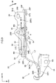
- a vehicle pop-up hood device 20 (referred to below as the "PUH device 20"), as an example of an exemplary embodiment according to technology disclosed herein, with reference to the drawings.
- the arrow FR, the arrow UP, and the arrow RH respectively indicate a front direction (direction of progress), an upward direction, and a right direction of a vehicle applied with the PUH device 20.
- reference simply to the front and rear, up and down, and left and right directions refers to the front and rear in a vehicle front-rear direction, up and down in a vehicle up-down direction, and left and right in a vehicle left-right direction (vehicle width direction).
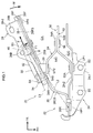
- the PUH devices 20 of an exemplary embodiment according to technology disclosed herein are each configured by a hood hinge with a pop-up function, and are provided with a function of popping up (lifting) a rear end section 10R of a front hood 10, serving as an example of a "hood" according to technology disclosed herein, from a closed position indicated by intermittent lines to a lifted position indicated by solid lines.
- a schematic configuration of the front hood 10 followed by explanation regarding the PUH devices 20.
- the front hood 10 extends along the front-rear direction and the width direction (left-right direction), and is formed in a substantially rectangular shape in vehicle plan view.
- the front hood 10 covers a power unit room ER that houses a power unit, not illustrated in the drawings, from an upper side.
- the rear end section 10R of the front hood 10 is swingably supported by a pair of left and right PUH devices 20 disposed separated from each other in the vehicle width direction. In other words, both vehicle width direction end portions of the rear end section 10R of the front hood 10 are swingably supported by the PUH devices 20.
- PUH devices 20 As illustrated in Fig.
- a hood striker 12 is fixed to a vehicle width direction intermediate portion of a front end section 10F of the front hood 10.
- the front hood 10 is retained in the closed position (namely, the front hood 10 is restricted from swinging) by anchoring the hood striker 12 to a single hood lock device 14 disposed at a vehicle width direction intermediate portion of a front end section of a vehicle body.
- the PUH devices 20 are respectively installed at both vehicle width direction end portions of the rear end section 10R of the front hood 10, and are configured with left-right symmetry to each other. Accordingly, the following explanation describes the PUH device 20 disposed on the right side, and explanation regarding the PUH device 20 disposed on the left side is omitted.
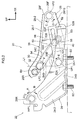
- the PUH device 20 is configured including a hood hinge 22 that supports the front hood 10 so as to be capable of opening and closing, an actuator 30 that actuates in the event of a collision between the vehicle and a pedestrian, and an oscillation suppressing mechanism 50 for suppressing oscillation of the front hood 10 after actuation of the actuator 30.
- a hood hinge 22 that supports the front hood 10 so as to be capable of opening and closing
- an actuator 30 that actuates in the event of a collision between the vehicle and a pedestrian
- an oscillation suppressing mechanism 50 for suppressing oscillation of the front hood 10 after actuation of the actuator 30.
- the hood hinge 22 is configured including a hinge base 24 that is fixed to the vehicle body, a first arm 26 that is coupled to the hinge base 24 so as to be capable of swinging, and a second arm 28 that is coupled to the first arm 26 so as to be capable of swinging and that is fixed to the rear end section 10R of the front hood 10 via hinge bolts B1 (see Fig. 7 ), serving as an example of "fastening members" according to technology disclosed herein.
- the hinge base 24 is, for example, formed by pressing a sheet steel member, and is bent substantially into an inverted L-shape as viewed from the front of the vehicle.
- a lower end portion of the hinge base 24 configures an attachment wall portion 24-1.
- the attachment wall portion 24-1 has a plate thickness direction running substantially in the up-down direction, and extends along the front-rear direction.
- the attachment wall portion 24-1 is fixed to the vehicle body by attachment bolts B2, and the attachment bolts B2 are disposed with a specific spacing between each other in the front-rear direction.
- the hinge base 24 includes a side wall portion 24-2.
- the side wall portion 24-2 extends from a vehicle width direction inner side end of the attachment wall portion 24-1 toward the upper side.
- the side wall portion 24-2 is formed substantially in a V-shape, opening toward the oblique upper front as viewed from the side of the vehicle.
- the hinge base 24 is formed with a bead portion 24B.
- the bead portion 24B extends from a vehicle width direction outer side end of the attachment wall portion 24-1 toward the vehicle width direction inner side, and extends from a lower end of the side wall portion 24-2 toward the upper side.
- the first arm 26 is, for example, formed by pressing a sheet steel member similarly to the hinge base 24, and is bent substantially into a crank shape in plan view.
- the first arm 26 includes a rear end wall 26R disposed with a plate thickness direction in the vehicle width direction, an intermediate inclined wall 26CS inclined toward the vehicle width direction inner side on progression from a front end of the rear end wall 26R toward the front side, and a front side inclined wall 26FS inclined toward the vehicle width direction inner side on progression from a front end of the intermediate inclined wall 26CS toward the front side.
- the angle of inclination of the intermediate inclined wall 26CS with respect to the front-rear direction is set larger than the angle of inclination of the front side inclined wall 26FS with respect to the front-rear direction.
- the intermediate inclined wall 26CS of the first arm 26 is inclined toward the vehicle width direction inner side on progression toward the front side in vehicle plan view. Accordingly, the front side inclined wall 26FS of the first arm 26 is disposed further to the vehicle width direction inner side than the rear end wall 26R of the first arm 26. A portion (area) between the front side inclined wall 26FS of the first arm 26 and the hinge base 24 configures a housing area CA that houses the oscillation suppressing mechanism 50, described later.
- a lower portion of a length direction intermediate portion of the front side inclined wall 26FS is formed with a first protruding portion 26B that protrudes out toward the vehicle width direction inner side.
- a front portion of the first protruding portion 26B is integrally provided with a first coupling bolt B3, serving as an example of a "first coupling shaft” according to technology disclosed herein, for attaching the actuator 30, described later.
- the first coupling bolt B3 projects out toward the vehicle width direction inner side with an axial direction running along the plate thickness direction of the front side inclined wall 26FS.
- the first coupling bolt B3 is inclined toward the rear side on progression toward the vehicle width direction inner side, and is orthogonal to the front side inclined wall 26FS (see Fig. 1 ). Moreover, the first coupling bolt B3 is disposed at the front side and the vehicle width direction inner side of the first hinge pin HP 1.
- a front end portion 28F of the side wall portion 28-1 (second arm 28) is coupled to a front end portion 26F of the first arm 26 (front side inclined wall 26FS) so as to be capable of swinging by a second hinge pin HP2, serving as a "second pin” of an example of technology disclosed herein.
- the (axial direction of the) second hinge pin HP2 is disposed parallel to the (axial direction of the) first coupling bolt B3. Namely, the (axial direction of the) second hinge pin HP2 is inclined toward the rear side on progression toward the vehicle width direction inner side in vehicle plan view, is disposed orthogonally to the front side inclined wall 26FS and the side wall portion 28-1, and is disposed at the front side and vehicle width direction inner side of the first hinge pin HP1.
- the second arm 28 is thereby capable of swinging about the second hinge pin HP2 so as to swing in the up-down direction (the arrow C direction and the arrow D direction in Fig. 2 ) relative to the first arm 26.
- the side wall portion 28-1 of the second arm 28 is formed with a shear pin insertion hole 28A (see Fig. 3 ) penetrating at a position corresponding to the shear pin insertion hole 26C of the first arm 26 described above.
- a shear pin not illustrated in the drawings, is fitted into the shear pin insertion hole 26C of the first arm 26 and the shear pin insertion hole 28A of the second arm 28, thereby joining the second arm 28 to the first arm 26. Accordingly, the second arm 28 is restricted from swinging relative to the first arm 26 in a non-actuated state of the actuator 30, described later.
- (an axial line of) the second coupling bolt B4 is disposed parallel to (the axial line of) the first coupling bolt B3, and is disposed inclined toward the rear side on progression toward the vehicle width direction inner side, and orthogonally to the side wall portion 28-1 in vehicle plan view (see Fig. 1 ).
- the hood hinge 22 configured as described above functions as a hinge component that swingably supports the front hood 10. Namely, during normal opening and closing of the front hood 10, the front hood 10 is opened and closed by swinging the first arm 26 with respect to the hinge base 24 about the first hinge pin HP1, in a state in which the first arm 26 and the second arm 28 are restricted from swinging relative to each other.
- the actuator 30 is formed in a substantially circular column shape, and is disposed at the vehicle width direction inner side of the second arm 28.
- the actuator 30 extends so as to span between the first coupling bolt B3 of the first arm 26 and the second coupling bolt B4 of the second arm 28.
- the actuator 30 is disposed along the side wall portion 28-1 of the second arm 28, and is inclined toward the vehicle width direction inner side on progression toward the front side.
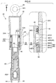
- the actuator 30 includes a cylinder 32, a rod 40, and a retention mechanism 48.
- the cylinder 32 is formed in a bottomed, substantially circular cylinder shape opening toward a lower side (a lower end side of the actuator 30).
- An upper end portion of the cylinder 32 is integrally provided with an upper end side attachment portion 34, and an attachment hole 34A is formed penetrating the upper end side attachment portion 34.
- the attachment hole 34A is disposed coaxially to the second coupling bolt B4 of the second arm 28 described above, and the second coupling bolt B4 is inserted into the attachment hole 34A, thereby swingably supporting the upper end side attachment portion 34.
- the upper end portion of the cylinder 32 is thereby attached so as to be capable of swinging relative to the second arm 28 (see Fig. 1 ).
- a head portion 36 is provided at an inner peripheral portion of a lower end portion of the cylinder 32.
- the head portion 36 is formed in a substantially circular cylinder shape, and is fixed to an inner peripheral portion of the cylinder 32.
- a housing groove 36A configuring the retention mechanism 48 is formed at an inner peripheral portion of the head portion 36.
- the housing groove 36A extends around a circumferential direction of the head portion 36, and is formed running around the entire circumference of the head portion 36.
- the housing groove 36A is formed with a substantially U-shaped cross-section profile opening toward a radial direction inner side of the cylinder 32.
- a lock ring 38 configuring the retention mechanism 48 (an element understood as falling under the broad definition of a "retention member”) is disposed (housed) inner side the housing groove 36A.
- the lock ring 38 is configured by a metal wire member with a circular cross-section profile, and is formed in an annular shape (ring shape) with an open portion. In other words, the lock ring 38 is formed in a substantially C-shape.
- the lock ring 38 has spring properties, and is configured so as to be capable of elastically deforming in its radial direction.
- the lock ring 38 is housed inner side the housing groove 36A in a state elastically deformed from its natural state (a state in which the lock ring 38 is not elastically deformed) toward the radial direction outer side, and abutting an outer peripheral portion of the rod 40, described later.
- An attachment hole 40A is formed penetrating the lower end portion of the rod 40.
- the attachment hole 40A is disposed coaxially to the first coupling bolt B3 of the first arm 26 described above, and the first coupling bolt B3 is inserted into the attachment hole 40A such that the lower end portion of the rod 40 is swingably supported.
- the lower end portion of the rod 40 is attached to the first arm 26 so as to be capable of swinging relative to the first arm 26 (see Fig. 1 ).
- a substantially circular cylinder shaped micro gas generator 42 (referred to below as the "MGG 42") is fitted into a length direction intermediate portion of the rod 40.
- the micro gas generator 42 includes a squib (ignition device), and the inner side of the MGG 42 is filled with a gas generating agent.
- Wire harnesses 44 are connected to a lower end of the micro gas generator 42, and the MGG 42 is electrically connected to an ECU 60 (see Fig. 5 and Fig. 8 ) through the wire harnesses 44.
- the MGG 42 is accordingly actuated under the control of the ECU 60. When the MGG 42 is actuated, gas generated by the MGG 42 is supplied inside the rod 40.
- a substantially annular shaped large diameter portion 40B is formed projecting out toward the radial direction outer side at an upper end portion of the rod 40.
- An external diameter dimension of the large diameter portion 40B is set slightly smaller than an internal diameter dimension of the cylinder 32.
- a sealing groove 40C is formed at an outer peripheral portion of the large diameter portion 40B.
- the sealing groove 40C is open toward the radial direction outer side of the rod 40 and extends around a circumferential direction of the large diameter portion 40B, and is formed running around the entire circumference of the large diameter portion 40B.
- An O-ring 46 configured by a rubber member or the like is disposed inside the sealing groove 40C, and the O-ring 46 seals between the rod 40 and the cylinder 32.
- a retention groove 40D configuring the retention mechanism 48 is formed in the outer peripheral portion of the rod 40 at a position further toward the lower end side of the rod 40 than the large diameter portion 40B.
- the retention groove 40D opens toward the radial direction outer side of the rod 40, extends around the circumferential direction of the rod 40, and is formed running around the entire circumference of the rod 40.
- the retention groove 40D is configured including a bottom face 40D1 disposed in the axial direction (the up-down direction) of the rod 40, an upper face 40D2 extending from an upper end of the bottom face 40D1 toward the radial direction outer side of the rod 40, and a lower inclined face 40D3 inclined toward the lower end side of the rod 40 on progression from a lower end of the bottom face 40D1 toward the radial direction outer side of the rod 40.
- setting is made such that when the cylinder 32 has been raised to the lifted position, the housing groove 36A is disposed at the radial direction outer side of the actuator 30 with respect to a lower end portion of the retention groove 40D of the rod 40.
- setting is made such that the housing groove 36A (the lock ring 38) and the lower end portion of the retention groove 40D are disposed facing each other in the radial direction of the actuator 30.
- the lock ring 38 undergoes elastic deformation toward the radial direction inner side (decreases in diameter), and enters the retention groove 40D, such that the lock ring 38 and the lower inclined face 40D3 of the retention groove 40D engage with each other.
- the groove depth of the retention groove 40D and the wire diameter of the lock ring 38 are set such that when this is performed, part of the lock ring 38 projects out further toward the radial direction outer side than the outer peripheral portion of the rod 40.
- the lock ring 38 is thereby interposed between the upper inclined face 36A2 of the housing groove 36A and the lower inclined face 40D3 of the retention groove 40D in the up-down direction, anchoring the cylinder 32 to the lock ring 38 at the location of the housing groove 36A.
- the cylinder 32 is thereby restricted from retracting, and movement of the front hood 10 toward the lower side when at the lifted position is restricted by the retention mechanism 48.
- a width dimension of the retention groove 40D (an up-down direction dimension of the bottom face 40D1) is set such that the cylinder 32 (lock ring 38) can be raised further than its position when actuation has been completed, illustrated in Fig. 6 .
- the oscillation suppressing mechanism 50 When the front hood 10 is in the closed position, the oscillation suppressing mechanism 50 is bent substantially into a V-shape, opening toward the rear side as viewed from the side (the state illustrated in Fig. 2 ; this state is referred to below as a "stowed state").
- the first link 52 is configured from a sheet metal material such as sheet steel, and is formed in a substantially elongated plate shape.
- the first link 52 configures a portion on one end side (a portion at a lower side) of the oscillation suppressing mechanism 50, and is disposed with a plate thickness direction in the vehicle width direction at the vehicle width direction inner side of the hinge base 24.
- the first link 52 is disposed at a slight incline toward the upper side on progression toward the front side.
- a first link pin LP1 with an axial direction in the vehicle width direction couples one end portion 52A of the first link 52 to a lower end portion of the side wall portion 24-2 of the hinge base 24 such that the one end portion 52A is capable of swinging.
- the first link pin LP1 is disposed at a front-rear direction intermediate portion of a lower end portion of the side wall portion 24-2 (see Fig. 2 ).
- a length direction intermediate portion of the first link 52 is formed with a first link intermediate portion 52C, and the first link intermediate portion 52C is inclined along the vehicle width direction toward the vehicle width direction inner side on progression toward another length direction side of the first link 52 (another end portion 52B side of the first link 52).
- the other end portion 52B is thereby disposed offset to the vehicle width direction inner side with respect to one end portion 52A of the first link 52.
- the circular shaped coupling hole 52D for coupling the second link 54 is formed penetrating the other end portion 52B of the first link 52.
- a slot 52E configuring the displacement mechanism 58 is formed penetrating the other end portion of the first link 52 on the other end side of the first link 52 to the coupling hole 52D.
- the slot 52E extends along the length direction of the first link 52, and one end of the slot 52E is in communication with the coupling hole 52D. In other words, the slot 52E extends out from the coupling hole 52D toward the other end side of the first link 52.
- a width dimension of the slot 52E is set smaller than a diameter dimension of the coupling hole 52D, and is set so as to be uniform throughout the length direction of the slot 52E.
- the circular retention hole 52F configuring the displacement mechanism 58 is formed penetrating the other end portion of the slot 52E, and a diameter dimension of the retention hole 52F is set so as to be the same as the diameter dimension of the coupling hole 52D.
- the second link 54 is configured from a sheet metal material such as sheet steel, and is formed in a substantially elongated plate shape.
- the second link 54 configures a portion on another end side (a portion at an upper side) of the oscillation suppressing mechanism 50, and is disposed at the vehicle width direction inner side of the first link 52 with a plate thickness direction in the vehicle width direction.
- the second link 54 is inclined toward the lower side on progression toward the front side.
- a length direction intermediate portion of the second link 54 is formed with a second link intermediate portion 54C (see Fig. 1 ).
- the second link intermediate portion 54C is inclined toward the vehicle width direction inner side on progression toward another length direction side of the second link 54 (another end portion 54B side of the second link 54). Accordingly, the other end portion 54B of the second link 54 is disposed offset to the vehicle width direction inner side with respect to the one end portion 54A of the second link 54.
- the other end portion 54B of the second link 54 is disposed adjacent on the vehicle width direction outer side to the leading end face of the stud 29 of the second arm 28, and is coupled to the stud 29 so as to be capable of swinging by a second link pin LP2 that has an axial direction running in the vehicle width direction.
- the other end portion 54B of the second link 54 is disposed adjacent on the front side to the second coupling bolt B4. More specifically, the second link pin LP2 is disposed adjacently on a radial direction outer side of the second coupling bolt B4 (see Fig. 2 ).
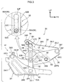
- the link shaft 56 is disposed at the front side of a hypothetical reference line L1 that passes through the axial center of the second link pin LP2 and runs in the up-down direction. Setting is made such that when the actuator 30 is actuated and the front hood 10 is lifted to the lifted position, the first link 52 swings relative to the hinge base 24 (see the arrow E in Fig. 2 ) and the second link 54 swings relative to the second arm 28 (see the arrow F in Fig. 2 ), and the oscillation suppressing mechanism 50 extends in a straight line shape running substantially in the up-down direction (the state illustrated in Fig. 3 ; this state is referred to below as an "actuated state").
- the link shaft 56 of the oscillation suppressing mechanism 50 is configured so as to move toward the upper side within the slot 52E, while enlarging the slot 52E toward the width direction outer side.
- the link shaft 56 moves toward the upper side along the slot 52E while sliding against inner peripheral faces of the slot 52E (see the link shaft 56 illustrated by double-dotted intermittent lines in the enlarged partial view in Fig. 3 ).
- the link shaft 56 that has moved toward the upper side along the slot 52E reaches the inner side of the retention hole 52F, actuation of the displacement mechanism 58 is complete, and the link shaft 56 is retained in the retention hole 52F (see Fig. 4 ).
- the other end portion of the oscillation suppressing mechanism 50 when the specific load toward the upper side is input to the other end portion of the oscillation suppressing mechanism 50 (the other end portion 54B of the second link 54), the other end portion of the oscillation suppressing mechanism 50 is displaced toward the upper side together with the front hood 10, and the front hood 10 is retained at a position further to the upper side than the lifted position (the position illustrated in Fig. 4 ; this position is referred to below as an "upper limit position").
- the frontal collision with the collision body is detected by a collision detection sensor (not illustrated in the drawings), and a collision signal is output to the ECU 60.
- a collision signal is output to the ECU 60.
- determination is made as to whether or not the PUH device 20 should be actuated based on the input collision signal.
- an actuation signal is output from the ECU 60 to the actuator 30.
- the squib of the MGG 42 of the actuator 30 is thereby ignited, and gas is supplied to the inside of the rod 40.
- the cylinder 32 When gas is supplied to the inside of the rod 40, the cylinder 32 is pressed by the pressure of the gas inside the rod 40, and the cylinder 32 rises in the axial direction of the rod 40. The cylinder 32 accordingly lifts the rear end portion 28R of the second arm 28, and both respective vehicle width direction end portions of the rear end section 10R of the front hood 10 are lifted to the lifted position (see the front hood 10 illustrated by solid lines in Fig. 7 ). Note that when this is performed, the shear pin joining between the second arm 28 and the first arm 26 snaps, and the second arm 28 swings toward the upper side (the arrow C direction side in Fig. 2 ) relative to the first arm 26, and the first arm 26 swings toward the upper side (the arrow A direction side in Fig.
- the oscillation suppressing mechanism 50 switches from the stowed state to the actuated state, and movement of the second arm 28 toward the upper side with respect to the hinge base 24 is restricted.
- the front side inclined wall 26FS of a first arm is disposed with a plate thickness direction in the vehicle width direction.
- the front side inclined wall 26FS extends along the front-rear direction in vehicle plan view.
- the second arm 28 and the actuator 30 also extend along the front-rear direction in vehicle plan view.
- the respective components illustrated in Fig. 9 are allocated the same reference numerals as those used in the present exemplary embodiment.
- first coupling bolt B3 and the second hinge pin HP2 are disposed at the front side and at the vehicle width direction inner side of the first hinge pin HP1.
- first coupling bolt B3 in vehicle plan view, the first coupling bolt B3, this being the point of action where actuation load F of the actuator 30 acts on the first arm 26, is disposed at the front side and vehicle width direction inner side of the first hinge pin HP1, this being the swing pivot point of the first arm 26.
- an imaginary line L2 connecting between the swing pivot point of the first arm 26 (a portion coupled by the first hinge pin HP1) and the point of action of the first arm 26 (the portion coupled to the actuator 30 by the first coupling bolt B3) is inclined toward the vehicle width direction inner side on progression toward the front side.
- the actuation load F of the actuator 30 input to the first coupling bolt B3 acts in a direction along an axial line L3 of the actuator 30. Namely, the actuation load F acts toward the front side in the first coupling bolt B3 in vehicle plan view. Since the direction of the actuation load F intersects the imaginary line L2, a component force F1 of the actuation load F orthogonal to and toward the vehicle width direction outer side of the imaginary line L2 acts at the location of the first coupling bolt B3 in the first arm 26. Accordingly, a clockwise rotation moment M (see the arrow M in Fig.
- the actuator 30 in vehicle plan view, is inclined toward the vehicle width direction inner side on progression toward the front side.
- the actuation load F of the actuator 30 input to the first coupling bolt B3 acts in a direction along the axial line L3 of the actuator 30.
- the actuation load F acts on the first coupling bolt B3 in a direction inclined toward the vehicle width direction inner side on progression toward the front side.
- the direction in which the actuation load F acts can thereby be brought closer to being parallel with the imaginary line L2 connecting between the swing pivot point of the first arm 26 (the first hinge pin HP1) and the point of action (the first coupling bolt B3).
- an angle ⁇ (angle of intersection) formed between the axial line L3 of the actuator 30 and the imaginary line L2 can be made smaller than in the comparative example. Accordingly, the component force F1 of the actuation load F orthogonal to and toward the vehicle width direction outer side of the imaginary line L2 can be reduced relative to the comparative example. As a result, the clockwise rotation moment M centered on the first hinge pin HP1 can be suppressed from arising in the first arm 26 (the rotation moment M arising in the first arm 26 can be reduced), thereby enabling flexural deformation of the first arm 26 to be suppressed.
- the hinge bolts B1 that fix the second arm 28 to the front hood 10 are disposed in a row in the front-rear direction, corresponding to the extension direction of the second arm 28.
- the hinge bolt B1 disposed at the front side is disposed at the vehicle width direction inner side of the hinge bolt B 1 disposed at the rear side. This thereby prevents a projection amount of the upper wall portion 28-2 of the second arm 28 from becoming large. Accordingly, an increase in size of the second arm 28 can be suppressed, thereby enabling an increase in size of the PUH device 20 to be suppressed.
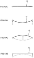
- Fig. 10A to Fig. 10D schematically illustrate states of the front hood 10 in time sequence when the actuator 30 lifts the front hood 10, as viewed from the rear side. Both vehicle width direction end portions of the front hood 10 are indicated by hollow circles.
- Fig. 10A illustrates a state prior to the actuator 30 lifting the front hood 10.
- the actuator 30 is in the non-actuated state illustrated in Fig. 5
- the oscillation suppressing mechanism 50 is in the stowed state illustrated in Fig. 2 .
- the cylinder 32 rises instantaneously with respect to the rod 40, and the front hood 10 is lifted to the lifted position.
- the gas escape holes 32A of the cylinder 32 are disposed further to the upper end side of the actuator 30 than the O-ring 46 of the rod 40. Accordingly, the gas in the inner side of the rod 40 is discharged through the gas escape holes 32A to outside the actuator 30. Lifting of the front hood 10 by the actuator 30 accordingly ceases.
- the lock ring 38 that rises together with the cylinder 32 is disposed between the lower end portion of the retention groove 40D of the rod 40 and the housing groove 36A of the cylinder 32.
- the oscillation suppressing mechanism 50 switches from the stowed state to the actuated state (switches from the state illustrated in Fig. 2 to the state illustrated in Fig. 3 ).
- the slot 52E of the displacement mechanism 58 is disposed so as to extend from the coupling hole 52D toward the upper side.
- the diameter dimension of the shaft portion 56A of the link shaft 56 coupling the first link 52 and the second link 54 together is set larger than the width dimension of the slot 52E, and so the link shaft 56 is retained inside the coupling hole 52D in the actuated state of the oscillation suppressing mechanism 50.
- displacement of the second arm 28 toward the upper side with respect to the hinge base 24 is restricted by the oscillation suppressing mechanism 50, and displacement of both respective vehicle width direction end portions of the rear end section 10R of the front hood 10 toward the upper side is restricted.
- the vehicle width direction central portion of the front hood 10 undergoing displacement toward the upper side is displaced (overshoots) further toward the upper side than the lifted position due to inertia (see the state in Fig. 10C ). Accordingly, during lifting of the front hood 10, the front hood 10 attempts to exhibit simple harmonic oscillation, with an antinode at the vehicle width direction central portion of the front hood 10, and with nodes at both vehicle width direction end portions of the front hood 10, as viewed from the rear side.
- the second arm 28 accordingly swings toward the upper side with respect to the first arm 26 and is displaced toward the upper side with respect to the hinge base 24, and the other end portion of the oscillation suppressing mechanism 50 is displaced to the upper limit position together with both respective vehicle width direction end portions of the front hood 10.
- both vehicle width direction end portions of the front hood 10 are displaced to the upper limit position (adopt the state in Fig. 10D from the state in Fig. 10C ).
- both vehicle width direction end portions of the front hood 10 open up such that the front hood 10 becomes substantially horizontal. Accordingly, oscillation arising in the front hood 10 by overshooting is attenuated at an early stage.
- the lock ring 38 moves from the lower end portion of the retention groove 40D toward the upper end portion of the retention groove 40D while sliding against the bottom face 40D1 (the cylinder 32 rises further with respect to the rod 40 from the state illustrated in Fig. 6 ).
- the oscillation suppressing mechanism 50 switches from the stowed state to the actuated state, and movement (displacement) of the second arm 28 toward the upper side with respect to the hinge base 24 is limited by the oscillation suppressing mechanism 50.
- the second arm 28 is coupled to the hinge base 24 that is fixed to a high rigidity location of the vehicle body via the oscillation suppressing mechanism 50, thereby enabling movement of the second arm 28 toward the upper side with respect to the hinge base 24 to be restricted.
- the actuator 30 is inclined toward the vehicle width direction inner side on progression toward the front side in vehicle plan view
- the axial line of the second hinge pin HP2 is orthogonal to the actuator 30 in vehicle plan view.
- the axial line of the second hinge pin HP2 is inclined toward the rear side on progression toward the vehicle width direction inner side in vehicle plan view. Accordingly, when the second arm 28 swings about the axis of the second hinge pin HP2 and lifts the vehicle width direction outer side end portion of the rear section of the front hood 10, (a fastening and fixing portion to the front hood 10 of) the second arm 28 is displaced toward the front side and the vehicle width direction inner side in vehicle plan view (see the arrow G in Fig. 8 ).
- the front hood 10 accordingly flexes such that both vehicle width direction end portions of the rear end section 10R of the front hood 10 are displaced toward the vehicle width direction central side by the second arm 28. Oscillation energy of the front hood 10 arising when the front hood 10 is lifted is expended in flexural deformation of the front hood 10, thereby enabling oscillation of the front hood 10 to be further suppressed.
- the oscillation suppressing mechanism 50 is disposed between the front side inclined wall 26FS of the first arm 26 and the second arm 28, and the hinge base 24 (namely, in the housing area CA).
- the housing area CA is thereby effectively utilized since the oscillation suppressing mechanism 50 that suppresses oscillation of the front hood 10 can be disposed in the housing area CA.
- the hinge base 24 and the second arm 28 are coupled together by the oscillation suppressing mechanism 50 that has switched to the actuated state. This thereby enables the front hood 10 to be suppressed from retreating toward the rear side when a body collides with the front hood 10 that has popped up.
- the oscillation suppressing mechanism 50 is configured by the link mechanism including the first link 52 and the second link 54, and the first link 52 and the second link 54 are coupled together by the link shaft 56. This thereby enables the oscillation suppressing mechanism 50 to be switched from the stowed state to the actuated state using a simple configuration, corresponding to a swing mode of the first arm 26 and the second arm 28.
- the displacement mechanism 58 configured by the link shaft 56 and the slot 52E actuates when the vehicle width direction central portion of the rear end section 10R of the front hood 10 overshoots further to the upper side than the lifted position, and the specific load toward the upper side from the front hood 10 acts on the other end portion of the oscillation suppressing mechanism 50 (second link 54). Both vehicle width direction end portions of the front hood 10 are thereby permitted to move (displace) to the upper limit position that is further to the upper side than the lifted position. Accordingly, as described above, oscillation of the front hood 10 arising due to the vehicle width direction central portion overshooting toward the upper side can be attenuated at an early stage.
- the diameter dimension of the shaft portion 56A of the link shaft 56 is set larger than the width dimension of the slot 52E. Accordingly, during actuation of the displacement mechanism 58, the (shaft portion 56A of the) link shaft 56 moves from the coupling hole 52D toward the retention hole 52F while sliding against the inner peripheral faces of the slot 52E. This thereby enables oscillation energy of the front hood 10 to be absorbed by frictional force arising between the link shaft 56 and the slot 52E during actuation of the displacement mechanism 58. The oscillation attenuation effect of the displacement mechanism 58 can accordingly be enhanced.
- the displacement mechanism 58 includes the retention hole 52F formed at the other end portion of the slot 52E. At the upper limit position, the link shaft 56 is retained by the retention hole 52F. This thereby enables the front hood 10 to be retained at the upper limit position in a state in which oscillation of the front hood 10 is suppressed.
- the imaginary line L2 connecting between the swing pivot point and the point of action of the first arm 26, and the axial line L3 of the actuator 30 are configured so as to intersect each other in vehicle plan view.
- configuration may be made such that the imaginary line L2 and the axial line L3 of the actuator 30 are aligned in vehicle plan view.
- the intermediate inclined wall 26CS of the first arm 26 is omitted, and the front side inclined wall 26FS extends from a front end of the rear end wall 26R of the first arm 26 toward the vehicle width direction inner side on progression toward the front side.
- the angle of inclination, the position, and the like of the front side inclined wall 26FS may be modified as appropriate such that the axial line L3 of the actuator 30 and the imaginary line L2 are aligned with each other.
- the actuation load F from the actuator 30 can be made to act along the imaginary line L2. This thereby enables rotation moment arising in the first arm 26 during actuation of the actuator 30 to be further suppressed, and enables flexural deformation of the first arm 26 to be further suppressed.
- the hinge bolts B1 for fixing the second arm 28 to the front hood 10 are disposed in a row along the front-rear direction so as to follow the extension direction of the second arm 28 in vehicle plan view.
- the hinge bolt B 1 disposed at the front side is disposed at the vehicle width direction inner side of the hinge bolt B 1 disposed at the rear side; however, the positions of the hinge bolts B1 in the vehicle width direction may be modified as appropriate.
- the positions of the vehicle width direction positions of the hinge bolt B 1 disposed at the front side and the hinge bolt B 1 disposed at the rear side may be aligned with each other in the vehicle width direction.
- the oscillation suppressing mechanism 50 is preferably provided with the displacement mechanism 58, as in the present exemplary embodiment.
- the displacement mechanism 58 may therefore be omitted from the oscillation suppressing mechanism 50. Namely, the slot 52E of the first link 52 may be omitted.
- the actuator 30 and the oscillation suppressing mechanism 50 are respectively disposed at the vehicle width direction inner side and the vehicle width direction outer side of the first arm 26 and the second arm 28.
- the placement of the actuator 30 and the oscillation suppressing mechanism 50 is not limited thereto.
- the actuator 30 and the oscillation suppressing mechanism 50 may both be disposed at the vehicle width direction outer side of the first arm 26 and the second arm 28, or may both be disposed at the vehicle width direction inner side of the first arm 26 and the second arm 28.
- the placement of the actuator 30 and the oscillation suppressing mechanism 50 may accordingly be set as appropriate in consideration of, for example, the clearance from other members peripheral to the hood hinge 22.
- the present exemplary embodiment describes the PUH device 20; however, a vehicle pop-up hood device of the present disclosure is not limited to the above, and obviously various other modifications may be implemented within a range not departing from the spirit of the present disclosure.
Landscapes
- Engineering & Computer Science (AREA)
- Mechanical Engineering (AREA)
- Chemical & Material Sciences (AREA)
- Combustion & Propulsion (AREA)
- Transportation (AREA)
- Superstructure Of Vehicle (AREA)
Applications Claiming Priority (1)
| Application Number | Priority Date | Filing Date | Title |
|---|---|---|---|
| JP2015164086A JP6245235B2 (ja) | 2015-08-21 | 2015-08-21 | 車両用ポップアップフード装置 |
Publications (3)
| Publication Number | Publication Date |
|---|---|
| EP3132983A2 true EP3132983A2 (de) | 2017-02-22 |
| EP3132983A3 EP3132983A3 (de) | 2017-03-01 |
| EP3132983B1 EP3132983B1 (de) | 2018-03-07 |
Family
ID=56787285
Family Applications (1)
| Application Number | Title | Priority Date | Filing Date |
|---|---|---|---|
| EP16184323.0A Not-in-force EP3132983B1 (de) | 2015-08-21 | 2016-08-16 | Fahrzeug mit anhebbarer haubenvorrichtung |
Country Status (4)
| Country | Link |
|---|---|
| US (1) | US9751493B2 (de) |
| EP (1) | EP3132983B1 (de) |
| JP (1) | JP6245235B2 (de) |
| CN (1) | CN106467140B (de) |
Cited By (1)
| Publication number | Priority date | Publication date | Assignee | Title |
|---|---|---|---|---|
| AT524574A4 (de) * | 2021-02-01 | 2022-07-15 | Astotec Automotive Gmbh | Aktuator zum Anheben einer Motorhaube |
Families Citing this family (8)
| Publication number | Priority date | Publication date | Assignee | Title |
|---|---|---|---|---|
| JP6413986B2 (ja) * | 2015-09-04 | 2018-10-31 | トヨタ自動車株式会社 | 車両用ポップアップフード装置 |
| JP6565764B2 (ja) * | 2016-03-30 | 2019-08-28 | 豊田合成株式会社 | アクチュエータ |
| US10434974B2 (en) * | 2016-09-22 | 2019-10-08 | Joyson Safety Systems Acquisition Llc | Hood lifting assembly |
| DE102018215767A1 (de) | 2018-09-17 | 2020-03-19 | Bayerische Motoren Werke Aktiengesellschaft | Scharniersystem einer Frontklappe eines Fahrzeugs |
| JP7064457B2 (ja) * | 2019-02-19 | 2022-05-10 | 本田技研工業株式会社 | 車両のポップアップフード装置 |
| JP7143237B2 (ja) * | 2019-03-11 | 2022-09-28 | 本田技研工業株式会社 | フードポップアップ構造 |
| DE102019106438B4 (de) | 2019-03-13 | 2022-10-20 | Edscha Engineering Gmbh | Aufstellbares Klappenscharnier |
| US12172699B2 (en) * | 2022-03-18 | 2024-12-24 | Nissan North America, Inc. | Hinge assembly for vehicle hood |
Citations (1)
| Publication number | Priority date | Publication date | Assignee | Title |
|---|---|---|---|---|
| JP2009202871A (ja) | 2008-02-28 | 2009-09-10 | Dr Ing Hcf Porsche Ag | 歩行者保護装置を備えたエンジンフード用ヒンジ構造 |
Family Cites Families (16)
| Publication number | Priority date | Publication date | Assignee | Title |
|---|---|---|---|---|
| DE10205626A1 (de) * | 2002-02-12 | 2003-08-14 | Suspa Tec Gmbh | Fußgänger-Schutz-Vorrichtung |
| FR2886612B1 (fr) * | 2005-06-06 | 2007-10-12 | Renault Sas | Dispositif de commande de l'ouverture du capot d'un vehicule, notamment pour proteger la tete d'un pieton en cas de choc. |
| US20070062747A1 (en) * | 2005-09-20 | 2007-03-22 | Erwin Gregory S | Hood hinge assembly for vehicle |
| JP5239253B2 (ja) * | 2007-08-14 | 2013-07-17 | 日産自動車株式会社 | フード跳ね上げ装置 |
| JP2009137507A (ja) * | 2007-12-10 | 2009-06-25 | Mitsubishi Motors Corp | 車両用フード跳ね上げ装置のヒンジ構造 |
| DE102009001273A1 (de) * | 2009-03-02 | 2010-09-09 | Ford Global Technologies, LLC, Dearborn | Kraftfahrzeug |
| CN201574648U (zh) * | 2009-11-26 | 2010-09-08 | 奇瑞汽车股份有限公司 | 一种汽车发动机罩用铰链 |
| CN102582568B (zh) * | 2011-01-17 | 2015-12-16 | 奥托立夫开发公司 | 用于抬起机动车辆车身件的装置 |
| KR101272517B1 (ko) * | 2011-08-01 | 2013-06-10 | 현대자동차주식회사 | 자동차용 액티브 후드 장치 |
| CN102582567B (zh) * | 2012-02-29 | 2014-04-02 | 华南理工大学 | 一种有利于行人保护的发动机罩弹起装置 |
| JP2014108651A (ja) * | 2012-11-30 | 2014-06-12 | Toyota Motor Corp | 車両用ポップアップフード装置 |
| US8768574B1 (en) * | 2013-02-22 | 2014-07-01 | Ventra Group, Inc. | Pedestrian protection vehicle hood hinge assembly |
| JP6003848B2 (ja) * | 2013-08-26 | 2016-10-05 | トヨタ自動車株式会社 | 車両用ポップアップフード装置 |
| KR101491310B1 (ko) * | 2013-09-04 | 2015-02-06 | 현대자동차주식회사 | 차량용 후드 장치 |
| US9701277B2 (en) * | 2015-02-25 | 2017-07-11 | Magna Closures Inc. | Active hinge with deployed position latch |
| JP6265185B2 (ja) * | 2015-09-02 | 2018-01-24 | トヨタ自動車株式会社 | 車両用ポップアップフード装置 |
-
2015
- 2015-08-21 JP JP2015164086A patent/JP6245235B2/ja not_active Expired - Fee Related
-
2016
- 2016-08-09 US US15/232,392 patent/US9751493B2/en not_active Expired - Fee Related
- 2016-08-15 CN CN201610671654.6A patent/CN106467140B/zh not_active Expired - Fee Related
- 2016-08-16 EP EP16184323.0A patent/EP3132983B1/de not_active Not-in-force
Patent Citations (1)
| Publication number | Priority date | Publication date | Assignee | Title |
|---|---|---|---|---|
| JP2009202871A (ja) | 2008-02-28 | 2009-09-10 | Dr Ing Hcf Porsche Ag | 歩行者保護装置を備えたエンジンフード用ヒンジ構造 |
Cited By (2)
| Publication number | Priority date | Publication date | Assignee | Title |
|---|---|---|---|---|
| AT524574A4 (de) * | 2021-02-01 | 2022-07-15 | Astotec Automotive Gmbh | Aktuator zum Anheben einer Motorhaube |
| AT524574B1 (de) * | 2021-02-01 | 2022-07-15 | Astotec Automotive Gmbh | Aktuator zum Anheben einer Motorhaube |
Also Published As
| Publication number | Publication date |
|---|---|
| US20170050610A1 (en) | 2017-02-23 |
| EP3132983A3 (de) | 2017-03-01 |
| EP3132983B1 (de) | 2018-03-07 |
| CN106467140B (zh) | 2018-11-27 |
| CN106467140A (zh) | 2017-03-01 |
| JP2017039469A (ja) | 2017-02-23 |
| US9751493B2 (en) | 2017-09-05 |
| JP6245235B2 (ja) | 2017-12-13 |
Similar Documents
| Publication | Publication Date | Title |
|---|---|---|
| EP3132983B1 (de) | Fahrzeug mit anhebbarer haubenvorrichtung | |
| CN106029454B (zh) | 车辆用弹起式发动机罩装置 | |
| JP4297161B2 (ja) | 車両用ポップアップフード装置 | |
| JP5239253B2 (ja) | フード跳ね上げ装置 | |
| JP6364533B2 (ja) | フロントフードのための歩行者保護手段が一体化されたヒンジ装置 | |
| JP4291850B2 (ja) | 車両用ポップアップフード装置 | |
| JP6200785B2 (ja) | ガス圧式アクチュエータ | |
| EP3095680B1 (de) | Fahrzeugaufstellhaubenvorrichtung | |
| JP2008247259A (ja) | 車両用ポップアップフード装置 | |
| JP2017180668A (ja) | アクチュエータ | |
| JP5765267B2 (ja) | 車両用ポップアップフード装置 | |
| JP6634326B2 (ja) | アクチュエータ | |
| JP3883982B2 (ja) | 自動車用安全装置 | |
| JP6287790B2 (ja) | フード跳ね上げ装置 | |
| JP6477376B2 (ja) | 車両用ポップアップフード装置 | |
| JP7632336B2 (ja) | アクチュエータ | |
| JP6337765B2 (ja) | フード跳ね上げ装置 | |
| JP6413986B2 (ja) | 車両用ポップアップフード装置 | |
| JP2009154596A (ja) | 車両用ポップアップフード装置 | |
| JP2018100687A (ja) | アクチュエータ | |
| JP2004352125A (ja) | 閉鎖部材の開放操作装置 | |
| JP2017100678A (ja) | 車両用ポップアップフード装置 | |
| JP2021055675A (ja) | アクチュエータ |
Legal Events
| Date | Code | Title | Description |
|---|---|---|---|
| PUAI | Public reference made under article 153(3) epc to a published international application that has entered the european phase |
Free format text: ORIGINAL CODE: 0009012 |
|
| STAA | Information on the status of an ep patent application or granted ep patent |
Free format text: STATUS: REQUEST FOR EXAMINATION WAS MADE |
|
| PUAL | Search report despatched |
Free format text: ORIGINAL CODE: 0009013 |
|
| 17P | Request for examination filed |
Effective date: 20160816 |
|
| AK | Designated contracting states |
Kind code of ref document: A2 Designated state(s): AL AT BE BG CH CY CZ DE DK EE ES FI FR GB GR HR HU IE IS IT LI LT LU LV MC MK MT NL NO PL PT RO RS SE SI SK SM TR |
|
| AX | Request for extension of the european patent |
Extension state: BA ME |
|
| AK | Designated contracting states |
Kind code of ref document: A3 Designated state(s): AL AT BE BG CH CY CZ DE DK EE ES FI FR GB GR HR HU IE IS IT LI LT LU LV MC MK MT NL NO PL PT RO RS SE SI SK SM TR |
|
| AX | Request for extension of the european patent |
Extension state: BA ME |
|
| RIC1 | Information provided on ipc code assigned before grant |
Ipc: B60R 21/38 20110101AFI20170125BHEP |
|
| GRAP | Despatch of communication of intention to grant a patent |
Free format text: ORIGINAL CODE: EPIDOSNIGR1 |
|
| STAA | Information on the status of an ep patent application or granted ep patent |
Free format text: STATUS: GRANT OF PATENT IS INTENDED |
|
| INTG | Intention to grant announced |
Effective date: 20170918 |
|
| RIN1 | Information on inventor provided before grant (corrected) |
Inventor name: NARITA, SOTARO |
|
| GRAS | Grant fee paid |
Free format text: ORIGINAL CODE: EPIDOSNIGR3 |
|
| GRAA | (expected) grant |
Free format text: ORIGINAL CODE: 0009210 |
|
| STAA | Information on the status of an ep patent application or granted ep patent |
Free format text: STATUS: THE PATENT HAS BEEN GRANTED |
|
| AK | Designated contracting states |
Kind code of ref document: B1 Designated state(s): AL AT BE BG CH CY CZ DE DK EE ES FI FR GB GR HR HU IE IS IT LI LT LU LV MC MK MT NL NO PL PT RO RS SE SI SK SM TR |
|
| REG | Reference to a national code |
Ref country code: GB Ref legal event code: FG4D |
|
| REG | Reference to a national code |
Ref country code: CH Ref legal event code: EP Ref country code: AT Ref legal event code: REF Ref document number: 976204 Country of ref document: AT Kind code of ref document: T Effective date: 20180315 |
|
| REG | Reference to a national code |
Ref country code: DE Ref legal event code: R096 Ref document number: 602016001833 Country of ref document: DE |
|
| REG | Reference to a national code |
Ref country code: IE Ref legal event code: FG4D |
|
| REG | Reference to a national code |
Ref country code: DE Ref legal event code: R084 Ref document number: 602016001833 Country of ref document: DE |
|
| REG | Reference to a national code |
Ref country code: GB Ref legal event code: 746 Effective date: 20180530 |
|
| REG | Reference to a national code |
Ref country code: NL Ref legal event code: MP Effective date: 20180307 |
|
| REG | Reference to a national code |
Ref country code: FR Ref legal event code: PLFP Year of fee payment: 3 |
|
| REG | Reference to a national code |
Ref country code: LT Ref legal event code: MG4D |
|
| PG25 | Lapsed in a contracting state [announced via postgrant information from national office to epo] |
Ref country code: ES Free format text: LAPSE BECAUSE OF FAILURE TO SUBMIT A TRANSLATION OF THE DESCRIPTION OR TO PAY THE FEE WITHIN THE PRESCRIBED TIME-LIMIT Effective date: 20180307 Ref country code: LT Free format text: LAPSE BECAUSE OF FAILURE TO SUBMIT A TRANSLATION OF THE DESCRIPTION OR TO PAY THE FEE WITHIN THE PRESCRIBED TIME-LIMIT Effective date: 20180307 Ref country code: CY Free format text: LAPSE BECAUSE OF FAILURE TO SUBMIT A TRANSLATION OF THE DESCRIPTION OR TO PAY THE FEE WITHIN THE PRESCRIBED TIME-LIMIT Effective date: 20180307 Ref country code: HR Free format text: LAPSE BECAUSE OF FAILURE TO SUBMIT A TRANSLATION OF THE DESCRIPTION OR TO PAY THE FEE WITHIN THE PRESCRIBED TIME-LIMIT Effective date: 20180307 Ref country code: NO Free format text: LAPSE BECAUSE OF FAILURE TO SUBMIT A TRANSLATION OF THE DESCRIPTION OR TO PAY THE FEE WITHIN THE PRESCRIBED TIME-LIMIT Effective date: 20180607 Ref country code: FI Free format text: LAPSE BECAUSE OF FAILURE TO SUBMIT A TRANSLATION OF THE DESCRIPTION OR TO PAY THE FEE WITHIN THE PRESCRIBED TIME-LIMIT Effective date: 20180307 |
|
| REG | Reference to a national code |
Ref country code: AT Ref legal event code: MK05 Ref document number: 976204 Country of ref document: AT Kind code of ref document: T Effective date: 20180307 |
|
| PG25 | Lapsed in a contracting state [announced via postgrant information from national office to epo] |
Ref country code: RS Free format text: LAPSE BECAUSE OF FAILURE TO SUBMIT A TRANSLATION OF THE DESCRIPTION OR TO PAY THE FEE WITHIN THE PRESCRIBED TIME-LIMIT Effective date: 20180307 Ref country code: GR Free format text: LAPSE BECAUSE OF FAILURE TO SUBMIT A TRANSLATION OF THE DESCRIPTION OR TO PAY THE FEE WITHIN THE PRESCRIBED TIME-LIMIT Effective date: 20180608 Ref country code: BG Free format text: LAPSE BECAUSE OF FAILURE TO SUBMIT A TRANSLATION OF THE DESCRIPTION OR TO PAY THE FEE WITHIN THE PRESCRIBED TIME-LIMIT Effective date: 20180607 Ref country code: LV Free format text: LAPSE BECAUSE OF FAILURE TO SUBMIT A TRANSLATION OF THE DESCRIPTION OR TO PAY THE FEE WITHIN THE PRESCRIBED TIME-LIMIT Effective date: 20180307 Ref country code: SE Free format text: LAPSE BECAUSE OF FAILURE TO SUBMIT A TRANSLATION OF THE DESCRIPTION OR TO PAY THE FEE WITHIN THE PRESCRIBED TIME-LIMIT Effective date: 20180307 |
|
| PG25 | Lapsed in a contracting state [announced via postgrant information from national office to epo] |
Ref country code: RO Free format text: LAPSE BECAUSE OF FAILURE TO SUBMIT A TRANSLATION OF THE DESCRIPTION OR TO PAY THE FEE WITHIN THE PRESCRIBED TIME-LIMIT Effective date: 20180307 Ref country code: PL Free format text: LAPSE BECAUSE OF FAILURE TO SUBMIT A TRANSLATION OF THE DESCRIPTION OR TO PAY THE FEE WITHIN THE PRESCRIBED TIME-LIMIT Effective date: 20180307 Ref country code: AL Free format text: LAPSE BECAUSE OF FAILURE TO SUBMIT A TRANSLATION OF THE DESCRIPTION OR TO PAY THE FEE WITHIN THE PRESCRIBED TIME-LIMIT Effective date: 20180307 Ref country code: NL Free format text: LAPSE BECAUSE OF FAILURE TO SUBMIT A TRANSLATION OF THE DESCRIPTION OR TO PAY THE FEE WITHIN THE PRESCRIBED TIME-LIMIT Effective date: 20180307 Ref country code: IT Free format text: LAPSE BECAUSE OF FAILURE TO SUBMIT A TRANSLATION OF THE DESCRIPTION OR TO PAY THE FEE WITHIN THE PRESCRIBED TIME-LIMIT Effective date: 20180307 Ref country code: EE Free format text: LAPSE BECAUSE OF FAILURE TO SUBMIT A TRANSLATION OF THE DESCRIPTION OR TO PAY THE FEE WITHIN THE PRESCRIBED TIME-LIMIT Effective date: 20180307 |
|
| PG25 | Lapsed in a contracting state [announced via postgrant information from national office to epo] |
Ref country code: SM Free format text: LAPSE BECAUSE OF FAILURE TO SUBMIT A TRANSLATION OF THE DESCRIPTION OR TO PAY THE FEE WITHIN THE PRESCRIBED TIME-LIMIT Effective date: 20180307 Ref country code: AT Free format text: LAPSE BECAUSE OF FAILURE TO SUBMIT A TRANSLATION OF THE DESCRIPTION OR TO PAY THE FEE WITHIN THE PRESCRIBED TIME-LIMIT Effective date: 20180307 Ref country code: SK Free format text: LAPSE BECAUSE OF FAILURE TO SUBMIT A TRANSLATION OF THE DESCRIPTION OR TO PAY THE FEE WITHIN THE PRESCRIBED TIME-LIMIT Effective date: 20180307 Ref country code: CZ Free format text: LAPSE BECAUSE OF FAILURE TO SUBMIT A TRANSLATION OF THE DESCRIPTION OR TO PAY THE FEE WITHIN THE PRESCRIBED TIME-LIMIT Effective date: 20180307 |
|
| REG | Reference to a national code |
Ref country code: DE Ref legal event code: R097 Ref document number: 602016001833 Country of ref document: DE |
|
| PG25 | Lapsed in a contracting state [announced via postgrant information from national office to epo] |
Ref country code: PT Free format text: LAPSE BECAUSE OF FAILURE TO SUBMIT A TRANSLATION OF THE DESCRIPTION OR TO PAY THE FEE WITHIN THE PRESCRIBED TIME-LIMIT Effective date: 20180709 |
|
| PLBE | No opposition filed within time limit |
Free format text: ORIGINAL CODE: 0009261 |
|
| STAA | Information on the status of an ep patent application or granted ep patent |
Free format text: STATUS: NO OPPOSITION FILED WITHIN TIME LIMIT |
|
| PG25 | Lapsed in a contracting state [announced via postgrant information from national office to epo] |
Ref country code: DK Free format text: LAPSE BECAUSE OF FAILURE TO SUBMIT A TRANSLATION OF THE DESCRIPTION OR TO PAY THE FEE WITHIN THE PRESCRIBED TIME-LIMIT Effective date: 20180307 |
|
| 26N | No opposition filed |
Effective date: 20181210 |
|
| PG25 | Lapsed in a contracting state [announced via postgrant information from national office to epo] |
Ref country code: SI Free format text: LAPSE BECAUSE OF FAILURE TO SUBMIT A TRANSLATION OF THE DESCRIPTION OR TO PAY THE FEE WITHIN THE PRESCRIBED TIME-LIMIT Effective date: 20180307 |
|
| PG25 | Lapsed in a contracting state [announced via postgrant information from national office to epo] |
Ref country code: MC Free format text: LAPSE BECAUSE OF FAILURE TO SUBMIT A TRANSLATION OF THE DESCRIPTION OR TO PAY THE FEE WITHIN THE PRESCRIBED TIME-LIMIT Effective date: 20180307 |
|
| PG25 | Lapsed in a contracting state [announced via postgrant information from national office to epo] |
Ref country code: LU Free format text: LAPSE BECAUSE OF NON-PAYMENT OF DUE FEES Effective date: 20180816 |
|
| REG | Reference to a national code |
Ref country code: BE Ref legal event code: MM Effective date: 20180831 |
|
| REG | Reference to a national code |
Ref country code: IE Ref legal event code: MM4A |
|
| PG25 | Lapsed in a contracting state [announced via postgrant information from national office to epo] |
Ref country code: IE Free format text: LAPSE BECAUSE OF NON-PAYMENT OF DUE FEES Effective date: 20180816 |
|
| PG25 | Lapsed in a contracting state [announced via postgrant information from national office to epo] |
Ref country code: BE Free format text: LAPSE BECAUSE OF NON-PAYMENT OF DUE FEES Effective date: 20180831 |
|
| PG25 | Lapsed in a contracting state [announced via postgrant information from national office to epo] |
Ref country code: MT Free format text: LAPSE BECAUSE OF NON-PAYMENT OF DUE FEES Effective date: 20180816 |
|
| PG25 | Lapsed in a contracting state [announced via postgrant information from national office to epo] |
Ref country code: TR Free format text: LAPSE BECAUSE OF FAILURE TO SUBMIT A TRANSLATION OF THE DESCRIPTION OR TO PAY THE FEE WITHIN THE PRESCRIBED TIME-LIMIT Effective date: 20180307 |
|
| PG25 | Lapsed in a contracting state [announced via postgrant information from national office to epo] |
Ref country code: LI Free format text: LAPSE BECAUSE OF NON-PAYMENT OF DUE FEES Effective date: 20190831 Ref country code: CH Free format text: LAPSE BECAUSE OF NON-PAYMENT OF DUE FEES Effective date: 20190831 |
|
| PG25 | Lapsed in a contracting state [announced via postgrant information from national office to epo] |
Ref country code: MK Free format text: LAPSE BECAUSE OF NON-PAYMENT OF DUE FEES Effective date: 20180307 Ref country code: HU Free format text: LAPSE BECAUSE OF FAILURE TO SUBMIT A TRANSLATION OF THE DESCRIPTION OR TO PAY THE FEE WITHIN THE PRESCRIBED TIME-LIMIT; INVALID AB INITIO Effective date: 20160816 |
|
| PG25 | Lapsed in a contracting state [announced via postgrant information from national office to epo] |
Ref country code: IS Free format text: LAPSE BECAUSE OF FAILURE TO SUBMIT A TRANSLATION OF THE DESCRIPTION OR TO PAY THE FEE WITHIN THE PRESCRIBED TIME-LIMIT Effective date: 20180707 |
|
| PGFP | Annual fee paid to national office [announced via postgrant information from national office to epo] |
Ref country code: FR Payment date: 20210715 Year of fee payment: 6 |
|
| PGFP | Annual fee paid to national office [announced via postgrant information from national office to epo] |
Ref country code: GB Payment date: 20210707 Year of fee payment: 6 |
|
| GBPC | Gb: european patent ceased through non-payment of renewal fee |
Effective date: 20220816 |
|
| P01 | Opt-out of the competence of the unified patent court (upc) registered |
Effective date: 20230427 |
|
| PG25 | Lapsed in a contracting state [announced via postgrant information from national office to epo] |
Ref country code: FR Free format text: LAPSE BECAUSE OF NON-PAYMENT OF DUE FEES Effective date: 20220831 |
|
| PG25 | Lapsed in a contracting state [announced via postgrant information from national office to epo] |
Ref country code: GB Free format text: LAPSE BECAUSE OF NON-PAYMENT OF DUE FEES Effective date: 20220816 |
|
| PGFP | Annual fee paid to national office [announced via postgrant information from national office to epo] |
Ref country code: DE Payment date: 20230627 Year of fee payment: 8 |
|
| REG | Reference to a national code |
Ref country code: DE Ref legal event code: R119 Ref document number: 602016001833 Country of ref document: DE |
|
| PG25 | Lapsed in a contracting state [announced via postgrant information from national office to epo] |
Ref country code: DE Free format text: LAPSE BECAUSE OF NON-PAYMENT OF DUE FEES Effective date: 20250301 |