EP3126636B1 - Verfahren und vorrichtung zur befestigung von brandschutzplatten - Google Patents
Verfahren und vorrichtung zur befestigung von brandschutzplatten Download PDFInfo
- Publication number
- EP3126636B1 EP3126636B1 EP15712311.8A EP15712311A EP3126636B1 EP 3126636 B1 EP3126636 B1 EP 3126636B1 EP 15712311 A EP15712311 A EP 15712311A EP 3126636 B1 EP3126636 B1 EP 3126636B1
- Authority
- EP
- European Patent Office
- Prior art keywords
- fire protection
- protection panel
- formwork
- retaining
- retaining device
- Prior art date
- Legal status (The legal status is an assumption and is not a legal conclusion. Google has not performed a legal analysis and makes no representation as to the accuracy of the status listed.)
- Active
Links
Images

Classifications
-
- E—FIXED CONSTRUCTIONS
- E21—EARTH OR ROCK DRILLING; MINING
- E21D—SHAFTS; TUNNELS; GALLERIES; LARGE UNDERGROUND CHAMBERS
- E21D11/00—Lining tunnels, galleries or other underground cavities, e.g. large underground chambers; Linings therefor; Making such linings in situ, e.g. by assembling
- E21D11/04—Lining with building materials
- E21D11/10—Lining with building materials with concrete cast in situ; Shuttering also lost shutterings, e.g. made of blocks, of metal plates or other equipment adapted therefor
- E21D11/102—Removable shuttering; Bearing or supporting devices therefor
-
- E—FIXED CONSTRUCTIONS
- E21—EARTH OR ROCK DRILLING; MINING
- E21D—SHAFTS; TUNNELS; GALLERIES; LARGE UNDERGROUND CHAMBERS
- E21D11/00—Lining tunnels, galleries or other underground cavities, e.g. large underground chambers; Linings therefor; Making such linings in situ, e.g. by assembling
- E21D11/38—Waterproofing; Heat insulating; Soundproofing; Electric insulating
Definitions
- the invention relates to a device for attaching fire protection panels to concrete structures, comprising a formwork for casting a concrete wall, at least one fire protection plate and at least one holding device for the fire protection board.
- fire protection boards consist of a refractory, heat-insulating material.
- Suitable fire protection boards are, for example, calcium silicate boards, cement silicate boards or gypsum-containing boards.
- Object of the present invention is therefore to optimize the attachment of the fire protection panels and simplify, and to present a method that simplifies the attachment of fire protection panels to concrete walls.
- This object is achieved by the invention in a surprisingly simple yet effective manner in that the fire protection plate on the side facing away from the concrete wall holding device, that the holding device is releasably secured to the fire protection board, that the fire protection board during concreting of the holding device and a attached thereto supporting device is held in position, and that the fire protection plate is inextricably connected after the concreting with the concrete wall.
- the holding device is fastened to the fire protection plate in such a way that it is fastened to the fire protection plate on the side facing away from the concrete. It thus does not come into contact with the concrete and can be easily removed by the releasable attachment after concreting.
- the fire protection plate with the holding device can be used both as a formwork for casting the concrete wall by the fire protection plate is releasably secured by means of the holding device to a support device, as well as to a existing formwork on the inside, z. B. are attached to a formwork.
- the effect is in both cases that the concreting concrete comes into contact with the fire protection board, connects to it, hardens and the fire protection plate is thus firmly concreted to the concrete wall.
- the fire protection plate is simply cemented during the casting of the wall. There is no further step to attach the fire protection boards necessary. There are also no screws, nails or rivets that can corrode and / or dissolve.
- the holding device is glued to the fire protection board. In this way - depending on the choice of adhesive - the fire protection plate remain undamaged. In particular, it is not necessary to introduce holes in the fire protection board, as would be the case with screws or rivets.
- the holding device is fastened to the fire protection plate with a double-sided adhesive tape.
- the formwork or support device has at least one retaining edge and the holding device has a bevel, which engages behind the retaining edge of the formwork.
- the fire protection plates can be easily and quickly hung.
- the retaining edge of the formwork is preferably an edge of an IPE carrier ("double-T-carrier").
- a support device of IPE-carriers is placed along the wall to be concreted.
- the fire protection plates can be hung so easily by means of the holding devices in the side edges of the IPE carrier.
- the holding device consists of sheet metal, spring steel or plastic.
- the holding device is reusable.
- the user does not have to rebuild the fixtures for each wall to be created, and there is a great deal of cost savings.
- Preferred is a variant of the method according to the invention, in which the holding device is removed simultaneously with the removal of the formwork or supporting device.
- the holding device is attached to the fire protection plate with a double-sided adhesive tape.
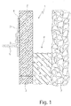
- Fig. 1 shows a schematic representation of an embodiment of the device 1 according to the invention in an exemplary installation or installation situation.
- a fire protection plate 2 is fastened by means of a holding device 3 to an IPE carrier of a supporting device 6 .
- the holding device 3 fastened with an adhesive 4 to the fire protection plate 2 covers the holding edge 5 of the supporting device 6.
- the fire protection plate 2 forms one side of the formwork 9 ( FIG. Fig. 3 ), a natural wall 7, for example a tunnel wall, forms the other side of the formwork 9.
- Flowable concrete 8 is then poured into the formwork between the fire protection plate 2 and the wall 7 (arrow) and hardens. In this curing process, one side of the fire protection plate 2 permanently connects to the hardened concrete 8.
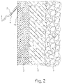
- Fig. 2 is the situation after a concreting example illustrated schematically.
- the concrete 8 is cured and now inseparably connected to the natural wall 7 and the fire protection plate 2.
- the supporting device 6 ( Fig. 1 ) has already been removed. Through the connection with the concrete 8, the fire protection plate 2 remains inextricably in their on or attachment position.
- the holding device 3 can now also be removed, unless it was already demolished when removing the support device 6 or removed with.
- the adhesive 4 is also removed. Any adhesive residues 4a are removed by suitable means of the fire protection plate 2 and any minor surface damage to the fire protection plate 2, which are caused by the removal of the adhesive 4 on the surface of the fire protection board 2, are repaired.
- Fig. 3 shows a schematic representation of another embodiment.
- one side of the formwork 9 is formed by the fire protection plate 2 itself, while the other side is formed by formwork panels 10 .
- the other side of the formwork 9 instead of formwork panels 10 are formed by further fire protection panels 2.
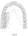
- Fig. 4 shows a schematic representation of an application example.
- the natural wall 7 may be a tunnel wall after boring the tunnel.
- these are reinforced with concrete 8.
- the walls are generally additionally clad with fire protection boards 2, so that in case of fire in the tunnel, the reinforcement made of concrete 8 or reinforced concrete is not damaged or protected and the tunnel remains functionally stable.
- the advantage of the method according to the invention is that the fire protection plates 2 and the concrete walls 8 have no holes for screws or rivets and also eliminates the amount of work for the subsequent screwing the fire protection plates 2 to the concrete walls 8.
Landscapes
- Engineering & Computer Science (AREA)
- Structural Engineering (AREA)
- Mining & Mineral Resources (AREA)
- Architecture (AREA)
- Civil Engineering (AREA)
- Life Sciences & Earth Sciences (AREA)
- General Life Sciences & Earth Sciences (AREA)
- Geochemistry & Mineralogy (AREA)
- Geology (AREA)
- Building Environments (AREA)
- Forms Removed On Construction Sites Or Auxiliary Members Thereof (AREA)
Description
- Die Erfindung betrifft eine Vorrichtung zum Anbringen von Brandschutzplatten an Betonbauwerken, umfassend eine Schalung zum Gießen einer Betonwand, zumindest eine Brandschutzplatte und zumindest eine Haltevorrichtung für die Brandschutzplatte.
- Beim Bau verschiedenster Bauwerke, insbesondere aber im Tunnelbau ist es vorgeschrieben, die Wände mit Brandschutzplatten zu verkleiden. Diese bestehen aus einem feuerfesten, wärmedämmenden Material. Als Brandschutzplatten kommen zum Beispiel Calcium-Silikat-Platten, Zement-Silikatplatten oder Gips enthaltende Platten in Frage.
- Diese werden üblicherweise auf den Beton der Tunnelwände aufgeklebt oder angedübelt. An Stellen, die schwer zu verkleiden sind, wie etwa Stahlträgern, sieht
DE 37 03 778 A1 vor, eine Haltevorrichtung an der Brandschutzplatte zu befestigen und die Brandschutzplatte mittels dieser Halterung an dem Träger über Schrauben zu fixieren. - Die nachträgliche Montage der Brandschutzplatten erfordert jedoch einen zusätzlichen Arbeitsschritt.
- Aus der
AT 414 009 B GB 582 725 A DE 198 00 559 A1 sind Brandschutzplatten bekannt geworden, die auf eine Deckenschalung aufgelegt werden. DieJP 2000 104223 A BE 488 032 A - Aufgabe der vorliegenden Erfindung ist es nun, die Befestigung der Brandschutzplatten zu optimieren und zu vereinfachen, sowie ein Verfahren vorzustellen, das die Befestigung von Brandschutzplatten an Betonwänden vereinfacht.
- Diese Aufgabe wird von der Erfindung auf überraschend einfache und doch effektive Weise dadurch gelöst, dass die Brandschutzplatte auf der der Betonwand abgewandten Seite die Haltevorrichtung aufweist, dass die Haltevorrichtung an der Brandschutzplatte lösbar befestigt ist, dass die Brandschutzplatte beim Betoniervorgang von der Haltevorrichtung und über eine daran angebrachte Stützvorrichtung in Position gehalten ist, und dass die Brandschutzplatte nach dem Betoniervorgang unlösbar mit der Betonwand verbunden ist.
- Die Haltevorrichtung ist derart an der Brandschutzplatte befestigt, dass sie auf der dem Beton abgewandten Seite an der Brandschutzplatte befestigt ist. Sie kommt somit mit dem Beton nicht in Berührung und kann durch die lösbare Befestigung nach dem Betonieren einfach entfernt werden.
- Die Brandschutzplatte mit der Haltevorrichtung kann sowohl selbst als Schalung zum Gießen der Betonwand verwendet werden, indem die Brandschutzplatte mittels der Haltvorrichtung an einer Stützvorrichtung lösbar befestigt wird, als auch an eine vorhandene Schalung auf der Innenseite, z. B. an einer Schalhaut befestigt werden. Der Effekt ist in beiden Fällen, dass beim Betonieren der Beton in Kontakt mit der Brandschutzplatte kommt, sich mit dieser verbindet, aushärtet und die Brandschutzplatte somit fest an die Betonwand anbetoniert ist.
- Auf diese Weise wird die Brandschutzplatte einfach beim Gießen der Wand festbetoniert. Es ist kein weiterer Arbeitsschritt zur Befestigung der Brandschutzplatten notwendig. Es gibt auch keine Schrauben, Nägel oder Nieten, die korrodieren und/oder sich lösen können.
- Die Haltevorrichtung ist an der Brandschutzplatte angeklebt. Auf diese Weise kann - je nach Wahl des Klebers - die Brandschutzplatte unbeschädigt bleiben. Insbesondere ist es nicht notwendig, Löcher in die Brandschutzplatte einzubringen, wie das etwa beim Schrauben oder Nieten der Fall wäre.
- Vorteilhaft und kostengünstig ist es, wenn die Haltevorrichtung mit einem doppelseitigen Klebeband an der Brandschutzplatte befestigt ist.
- Besonders bevorzugt wird eine Ausführungsform der erfindungsgemäßen Vorrichtung, bei welcher die Schalung oder Stützvorrichtung zumindest eine Haltekante aufweist und die Haltevorrichtung eine Kantung aufweist, welche die Haltekante der Schalung hintergreift. Bei einer derartigen Vorrichtung können die Brandschutzplatten einfach und schnell eingehängt werden.
- Die Haltekante der Schalung ist dabei vorzugsweise eine Kante eines IPE-Trägers ("Doppel-T-Träger"). Bei dieser Ausführungsform wird eine Stützvorrichtung aus IPE-Trägern entlang der zu betonierenden Wand aufgestellt. Die Brandschutzplatten können so einfach mittels der Haltevorrichtungen in die Seitenkanten der IPE-Träger eingehängt werden.
- Die Haltevorrichtung besteht aus Blech, Federstahl oder Kunststoff.
- Diese Materialien sind kostengünstig und baustellengerecht.
- Vorzugsweise ist die Haltevorrichtung wiederverwendbar. Dadurch muss der Anwender die Haltevorrichtungen nicht für jede zu erstellende Wand neu erstellen, und eine große Kosteneinsparung ist gegeben.
- Die Erfindung umfasst auch ein Verfahren zum Einbau von Brandschutzplatten in Betonbauwerke, umfassend die folgenden Verfahrensschritte:
- Aufbau einer Schalung oder Stützvorrichtung zum Gießen einer Betonwand;
- Befestigen einer Haltevorrichtung an der Brandschutzplatte mittels einer lösbaren Befestigung, wobei die Haltevorrichtung an der Brandschutzplatte angeklebt ist und wobei die Haltevorrichtung aus Blech, Federstahl oder Kunststoff besteht;
- Positionieren zumindest einer Brandschutzplatte in ihrer Ein- oder Anbauposition;
- befestigen der zumindest einen Brandschutzplatte in ihrer Ein- oder Anbauposition an der Schalung oder Stützvorrichtung;
- Eingießen des Betons in die Schalung oder in die mit der Stützvorrichung versehenen Brandschutzplatte;
- Entfernen der Schalung oder Stützvorrichtung und der Haltevorrichtung von der zumindest einen Brandschutzplatte.
- Bevorzugt wird eine Variante der erfindungsgemäßen Verfahrens, bei der die Haltevorrichtung beim Entfernen der Schalung oder Stützvorrichtung gleichzeitig mit entfernt wird.
- Dabei wird idealerweise die Haltevorrichtung mit einem doppelseitigen Klebeband an der Brandschutzplatte befestigt.
- Zeichnungen und Detailbeschreibung:
-
Fig. 1 zeigt eine schematische Darstellung eines Ausführungsbeispiels der erfindungsgemäßen Vorrichtung in einer beispielhaften An- bzw. Einbausituation; -
Fig. 2 zeigt eine schematische Darstellung eines Ausführungsbeispiels der erfindungsgemäßen Vorrichtung nach dem Betoniervorgang; -
Fig. 3 zeigt eine schematische Darstellung eines Ausführungsbeispiels der erfindungsgemäßen Vorrichtung in einer zweiten beispielhaften An- bzw. Einbausituation; -
Fig. 4 zeigt eine schematische Darstellung eines Anwendungsbeispiels der erfindungsgemäßen Vorrichtung bzw. des erfindungsgemäßen Verfahrens. -
Fig. 1 zeigt eine schematische Darstellung eines Ausführungsbeispiels der erfindungsgemäßen Vorrichtung 1 in einer beispielhaften An- bzw. Einbausituation. Eine Brandschutzplatte 2 ist mittels einer Haltevorrichtung 3 an einem IPE-Träger einer Stützvorrichtung 6 befestigt. Dabei hinterfasst die mit einem Kleber 4 an der Brandschutzplatte 2 befestigte Haltevorrichtung 3 die Haltekante 5 der Stützvorrichtung 6.
In dem hier gewählten Ausführungsbeispiel bildet die Brandschutzplatte 2 eine Seite der Schalung 9 (Fig. 3 ), eine natürliche Wand 7, zum Beispiel eine Tunnelwand, bildet die andere Seite der Schalung 9. Fließfähiger Beton 8 wird dann in die Schalung zwischen der Brandschutzplatte 2 und der Wand 7 gegossen (Pfeil) und härtet aus. Bei diesem Aushärtungsvorgang verbindet sich eine Seite der Brandschutzplatte 2 unlösbar mit dem ausgehärteten Beton 8. - In
Fig. 2 ist die Situation nach einem Betoniervorgang beispielhaft schematisch dargestellt. Der Beton 8 ist ausgehärtet und nunmehr unlösbar mit der natürlichen Wand 7 und der Brandschutzplatte 2 verbunden. Die Stützvorrichtung 6 (Fig. 1 ) wurde bereits entfernt. Durch die Verbindung mit dem Beton 8 verbleibt die Brandschutzplatte 2 unlösbar in ihrer Ein- bzw. Anbauposition. - Die Haltevorrichtung 3 kann jetzt ebenfalls entfernt werden, sofern sie nicht beim Entfernen der Stützvorrichtung 6 bereits abgerissen oder mit entfernt wurde. Der Kleber 4 wird ebenfalls entfernt. Eventuelle Kleberreste 4a werden mit geeigneten Mitteln von der Brandschutzplatte 2 abgetragen und eventuelle kleinere oberflächliche Beschädigungen an der Brandschutzplatte 2, die durch das Entfernen des Klebers 4 auf der Oberfläche der Brandschutzplatte 2 entstanden sind, werden ausgebessert.
- Die in der
Fig. 2 dargestellten Schichten im Schnitt, die Brandschutzplatte 2, der Beton 8 und die Wand 7 sind untrennbar miteinander verbunden. -
Fig. 3 zeigt eine schematische Darstellung eines weiteren Ausführungsbeispiels. Dabei wird eine Seite der Schalung 9 durch die Brandschutzplatte 2 selbst gebildet, während die andere Seite durch Schalungstafeln 10 gebildet wird. Alternativ kann die andere Seite der Schalung 9 statt durch Schalungstafeln 10 durch weitere Brandschutzplatten 2 gebildet werden. -
Fig. 4 zeigt eine schematische Darstellung eines Anwendungsbeispiels. So kann die natürliche Wand 7 zum Beispiel eine Tunnelwand nach dem Bohren des Tunnels sein. Um die Tunnelwände zu stabilisieren, werden diese mit Beton 8 armiert. Aufgrund von Brandschutzvorschriften sind im Allgemeinen die Wände zusätzlich mit Brandschutzplatten 2 zu verkleiden, damit bei einem Brand im Tunnel die Armierung aus Beton 8 bzw. Stahlbeton nicht beschädigt wird bzw. geschützt ist und der Tunnel funktionsstabil erhalten bleibt. Der Vorteil des erfindungsgemäßen Verfahrens ist, dass die Brandschutzplatten 2 und die Betonwände 8 keine Löcher für Schrauben oder Nieten aufweisen und auch der Arbeitsaufwand für das nachträgliche Anschrauben der Brandschutzplatten 2 an die Betonwände 8 entfällt.
Claims (8)
- Vorrichtung (1) zum Anbringen von Brandschutzplatten (2) an Betonbauwerken, umfassend eine Schalung zum Gießen einer Betonwand (8), zumindest eine Brandschutzplatte (2) und zumindest eine Haltevorrichtung (3) für die Brandschutzplatte (2),
dadurch gekennzeichnet,
dass die Brandschutzplatte (2) auf der der Betonwand (8) abgewandten Seite die Haltevorrichtung (3) aufweist,
dass die Haltevorrichtung (3) an der Brandschutzplatte (2) lösbar befestigt ist, wobei die Haltevorrichtung (3) an der Brandschutzplatte (2) angeklebt ist, dass die Brandschutzplatte (2) beim Betoniervorgang von der Haltevorrichtung (3) und über eine daran angebrachte Stützvorrichtung (6) in Position gehalten ist, und
dass die Brandschutzplatte (2) nach dem Betoniervorgang unlösbar mit der Betonwand (8) verbunden ist,
und dass die Haltevorrichtung (3) aus Blech, Federstahl oder Kunststoff besteht. - Vorrichtung (1) nach Anspruch 1, dadurch gekennzeichnet, dass die Haltevorrichtung (3) mit einem doppelseitigen Klebeband (4) an der Brandschutzplatte befestigt ist.
- Vorrichtung (1) nach einem der vorhergehenden Ansprüche, dadurch gekennzeichnet, dass die Schalung oder die Stützvorrichtung (6) zumindest eine Haltekante (5) aufweist, und
dass die Haltevorrichtung (3) eine Kantung aufweist, die die Haltekante (5) der Schalung oder Stützvorrichtung (6) hintergreift. - Vorrichtung (1) nach Anspruch 3, dadurch gekennzeichnet, dass die Haltekante (5) der Stützvorrichtung (6) eine Kante eines IPE-Trägers ist.
- Vorrichtung (1) nach einem der vorhergehenden Ansprüche, dadurch gekennzeichnet, dass die Haltevorrichtung (3) wiederverwendbar ist.
- Verfahren zum Anbringen von Brandschutzplatten an Betonbauwerken, umfassend die folgenden Verfahrensschritte:- Aufbau einer Schalung oder Stützvorrichtung (6) zum Gießen einer Betonwand (8);- Befestigen einer Haltvorrichtung (3) an der Brandschutzplatte (2) mittels einer lösbaren Befestigung (4), wobei die Haltevorrichtung (3) an der Brandschutzplatte (2) angeklebt ist, und wobei die Haltevorrichtung aus Blech, Federstahl oder Kunststoff besteht;- Positionieren zumindest einer Brandschutzplatte (2) in ihrer Ein- oder Anbauposition;- Befestigen der zumindest einen Brandschutzplatte (2) in ihrer Ein- oder Anbauposition an der Schalung oder Stützvorrichtung (6);- Eingießen des Betons (8) in die Schalung oder in die mit der Stützvorrichung versehenen Brandschutzplatte (2);- Entfernen der Schalung oder Stützvorrichtung (6) und der Haltevorrichtung (3) von der zumindest einen Brandschutzplatte (2).
- Verfahren nach Anspruch 6, dadurch gekennzeichnet, dass die Haltevorrichtung (3) beim Entfernen der Schalung oder Stützvorrichtung (6) gleichzeitig mit entfernt wird.
- Verfahren nach Anspruch 6 oder 7, dadurch gekennzeichnet, dass die Haltevorrichtung (3) mit einem doppelseitigen Klebeband (4) an der Brandschutzplatte (2) befestigt wird.
Applications Claiming Priority (2)
| Application Number | Priority Date | Filing Date | Title |
|---|---|---|---|
| DE102014206199.7A DE102014206199A1 (de) | 2014-04-01 | 2014-04-01 | Verfahren und Vorrichtung zur Befestigung von Brandschutzplatten |
| PCT/EP2015/055634 WO2015150076A2 (de) | 2014-04-01 | 2015-03-18 | Verfahren und vorrichtung zur befestigung von brandschutzplatten |
Publications (2)
| Publication Number | Publication Date |
|---|---|
| EP3126636A2 EP3126636A2 (de) | 2017-02-08 |
| EP3126636B1 true EP3126636B1 (de) | 2019-01-16 |
Family
ID=52779604
Family Applications (1)
| Application Number | Title | Priority Date | Filing Date |
|---|---|---|---|
| EP15712311.8A Active EP3126636B1 (de) | 2014-04-01 | 2015-03-18 | Verfahren und vorrichtung zur befestigung von brandschutzplatten |
Country Status (5)
| Country | Link |
|---|---|
| EP (1) | EP3126636B1 (de) |
| DE (1) | DE102014206199A1 (de) |
| DK (1) | DK3126636T3 (de) |
| ES (1) | ES2718407T3 (de) |
| WO (1) | WO2015150076A2 (de) |
Families Citing this family (1)
| Publication number | Priority date | Publication date | Assignee | Title |
|---|---|---|---|---|
| CN107060123B (zh) * | 2017-04-21 | 2023-08-15 | 山东兴华建设集团有限公司 | 一种钢管混凝土柱防火机构及其施工连接方法 |
Family Cites Families (8)
| Publication number | Priority date | Publication date | Assignee | Title |
|---|---|---|---|---|
| US1382668A (en) * | 1919-11-08 | 1921-06-28 | John F O'rourke | Means for supporting tunnel-lining segments |
| GB582725A (en) * | 1944-02-03 | 1946-11-26 | Alford Donald Gratton Wilson | Improved means for driving and lining tunnels |
| FR58586E (fr) * | 1948-04-29 | 1954-01-27 | Procédé et dispositif de réalisation de constructions creuses precontraintes radialement applicables en particulier aux travaux souterrains | |
| DE3703778A1 (de) | 1987-02-07 | 1988-08-18 | Manfred Monheimius | Vorrichtung zur befestigung von brandschutzplatten |
| DE29519543U1 (de) * | 1995-12-09 | 1996-04-04 | Dausend, Hans-Werner, 42289 Wuppertal | Wärmegedämmte Deckenrandabschalung |
| DE19800559C2 (de) * | 1997-11-03 | 2000-12-07 | Aestuver Sued Bauplatten Gmbh | Verfahren zum Herstellen einer vor Brandeinwirkung geschützten Betonkonstruktion |
| JP3215689B2 (ja) * | 1999-10-14 | 2001-10-09 | 株式会社ホーク | モルタル施工方法及びモルタル層構造 |
| AT414009B (de) * | 2002-04-17 | 2006-08-15 | Kubek Erhard Dipl Ing | Betonkonstruktion |
-
2014
- 2014-04-01 DE DE102014206199.7A patent/DE102014206199A1/de not_active Withdrawn
-
2015
- 2015-03-18 ES ES15712311T patent/ES2718407T3/es active Active
- 2015-03-18 WO PCT/EP2015/055634 patent/WO2015150076A2/de not_active Ceased
- 2015-03-18 EP EP15712311.8A patent/EP3126636B1/de active Active
- 2015-03-18 DK DK15712311.8T patent/DK3126636T3/en active
Non-Patent Citations (1)
| Title |
|---|
| None * |
Also Published As
| Publication number | Publication date |
|---|---|
| EP3126636A2 (de) | 2017-02-08 |
| WO2015150076A2 (de) | 2015-10-08 |
| DE102014206199A1 (de) | 2015-10-01 |
| WO2015150076A3 (de) | 2016-03-17 |
| DK3126636T3 (en) | 2019-04-23 |
| ES2718407T3 (es) | 2019-07-01 |
Similar Documents
| Publication | Publication Date | Title |
|---|---|---|
| DE102010047242B4 (de) | Fassadensystem | |
| EP3662116B1 (de) | Verfahren zum herstellen eines deckenelements und deckenschalung | |
| EP2182139B1 (de) | Verfahren zum Anbringen einer Verstärkung bzw. Verkleidung an einem bestehenden Bauteil sowie Bauteil mit daran angebrachter Verstärkungs- bzw. Verkleidungsschicht | |
| WO2015150076A2 (de) | Verfahren und vorrichtung zur befestigung von brandschutzplatten | |
| EP3990715B1 (de) | Verankerungselement und verfahren zur montage einer ankerschiene in einem baukörper aus beton | |
| DE102017213613B4 (de) | Verfahren zum Herstellen eines nachträglich zu verschließenden Deckendurchbruchs | |
| CH624446A5 (en) | End shuttering on a concrete floor | |
| DE202018100286U1 (de) | Mehrteiliges Putzanschlusselement | |
| EP1079037B1 (de) | Verfahren zur Erstellung einer Deckenrand-Abschalung sowie eine Deckenrand-Abschalung | |
| DE2124227C2 (de) | Verfahren zum Aufbringen von Kunststoff-Ankernoppen auf die Rückseite von großflächigen Auskleidungsplatten aus Kunststoff | |
| DE1659007A1 (de) | Vorrichtung zum Anschliessen von Stahlbetonbauteilen an in Wanderschalung hergestellte wandartige Stahlbetonbauteile | |
| DE202016005858U1 (de) | Innovatives System zur Befestigung von Anbauten an Betonteilen | |
| EP0892127B1 (de) | Schalung und Verfahren zum Erzeugen einer Sollrissstelle | |
| EP2881523A1 (de) | Verfahren zum Markieren eines Messpunkts in einer gegossenen Betondecke | |
| EP4357554B1 (de) | Verfahren und schalungssystem zum herstellen einer betonwand | |
| DE29519543U1 (de) | Wärmegedämmte Deckenrandabschalung | |
| AT101364B (de) | Freitragende Wand. | |
| DE2647508A1 (de) | Deckenrostschalungsstein | |
| DE964439C (de) | Vorrichtung zur Befestigung von Leichtbauplatten an aus Beton herzustellenden Decken, Waenden u. dgl. | |
| DE1096583B (de) | Aufhaengevorrichtung fuer die Befestigung von Unterdecken od. dgl. an Betonkonstruktionen | |
| AT519528B1 (de) | Vorrichtung zum lösbaren befestigen zumindest einer brüstung und/oder eines gerüstes | |
| DE102015017166B4 (de) | Randschalungselement mit einer als verlorene Schalung dienenden Schalungsplatte zur Herstellung einer Betonplatte | |
| AT255338B (de) | Verfahren zur Assanierung von Kanälen mit elliptischem Lichtprofil | |
| DE2345566A1 (de) | Schalungssystem | |
| DE8319670U1 (de) | Vorrichtung zum Verlegen von elektrischen Leitungsrohren od. dgl. |
Legal Events
| Date | Code | Title | Description |
|---|---|---|---|
| STAA | Information on the status of an ep patent application or granted ep patent |
Free format text: STATUS: THE INTERNATIONAL PUBLICATION HAS BEEN MADE |
|
| PUAI | Public reference made under article 153(3) epc to a published international application that has entered the european phase |
Free format text: ORIGINAL CODE: 0009012 |
|
| STAA | Information on the status of an ep patent application or granted ep patent |
Free format text: STATUS: REQUEST FOR EXAMINATION WAS MADE |
|
| 17P | Request for examination filed |
Effective date: 20161102 |
|
| AK | Designated contracting states |
Kind code of ref document: A2 Designated state(s): AL AT BE BG CH CY CZ DE DK EE ES FI FR GB GR HR HU IE IS IT LI LT LU LV MC MK MT NL NO PL PT RO RS SE SI SK SM TR |
|
| AX | Request for extension of the european patent |
Extension state: BA ME |
|
| DAV | Request for validation of the european patent (deleted) | ||
| DAX | Request for extension of the european patent (deleted) | ||
| STAA | Information on the status of an ep patent application or granted ep patent |
Free format text: STATUS: EXAMINATION IS IN PROGRESS |
|
| 17Q | First examination report despatched |
Effective date: 20180612 |
|
| GRAP | Despatch of communication of intention to grant a patent |
Free format text: ORIGINAL CODE: EPIDOSNIGR1 |
|
| STAA | Information on the status of an ep patent application or granted ep patent |
Free format text: STATUS: GRANT OF PATENT IS INTENDED |
|
| RIC1 | Information provided on ipc code assigned before grant |
Ipc: E21D 11/10 20060101AFI20180920BHEP Ipc: E21D 11/38 20060101ALI20180920BHEP |
|
| INTG | Intention to grant announced |
Effective date: 20181012 |
|
| GRAS | Grant fee paid |
Free format text: ORIGINAL CODE: EPIDOSNIGR3 |
|
| GRAA | (expected) grant |
Free format text: ORIGINAL CODE: 0009210 |
|
| STAA | Information on the status of an ep patent application or granted ep patent |
Free format text: STATUS: THE PATENT HAS BEEN GRANTED |
|
| AK | Designated contracting states |
Kind code of ref document: B1 Designated state(s): AL AT BE BG CH CY CZ DE DK EE ES FI FR GB GR HR HU IE IS IT LI LT LU LV MC MK MT NL NO PL PT RO RS SE SI SK SM TR |
|
| REG | Reference to a national code |
Ref country code: GB Ref legal event code: FG4D Free format text: NOT ENGLISH |
|
| REG | Reference to a national code |
Ref country code: CH Ref legal event code: EP |
|
| REG | Reference to a national code |
Ref country code: IE Ref legal event code: FG4D Free format text: LANGUAGE OF EP DOCUMENT: GERMAN |
|
| REG | Reference to a national code |
Ref country code: DE Ref legal event code: R096 Ref document number: 502015007711 Country of ref document: DE |
|
| REG | Reference to a national code |
Ref country code: AT Ref legal event code: REF Ref document number: 1089830 Country of ref document: AT Kind code of ref document: T Effective date: 20190215 |
|
| REG | Reference to a national code |
Ref country code: SE Ref legal event code: TRGR |
|
| REG | Reference to a national code |
Ref country code: DK Ref legal event code: T3 Effective date: 20190415 |
|
| PGFP | Annual fee paid to national office [announced via postgrant information from national office to epo] |
Ref country code: GB Payment date: 20190321 Year of fee payment: 5 |
|
| REG | Reference to a national code |
Ref country code: NL Ref legal event code: MP Effective date: 20190116 |
|
| REG | Reference to a national code |
Ref country code: CH Ref legal event code: NV Representative=s name: RENTSCH PARTNER AG, CH |
|
| REG | Reference to a national code |
Ref country code: LT Ref legal event code: MG4D |
|
| PG25 | Lapsed in a contracting state [announced via postgrant information from national office to epo] |
Ref country code: NL Free format text: LAPSE BECAUSE OF FAILURE TO SUBMIT A TRANSLATION OF THE DESCRIPTION OR TO PAY THE FEE WITHIN THE PRESCRIBED TIME-LIMIT Effective date: 20190116 |
|
| REG | Reference to a national code |
Ref country code: ES Ref legal event code: FG2A Ref document number: 2718407 Country of ref document: ES Kind code of ref document: T3 Effective date: 20190701 |
|
| PG25 | Lapsed in a contracting state [announced via postgrant information from national office to epo] |
Ref country code: PL Free format text: LAPSE BECAUSE OF FAILURE TO SUBMIT A TRANSLATION OF THE DESCRIPTION OR TO PAY THE FEE WITHIN THE PRESCRIBED TIME-LIMIT Effective date: 20190116 Ref country code: NO Free format text: LAPSE BECAUSE OF FAILURE TO SUBMIT A TRANSLATION OF THE DESCRIPTION OR TO PAY THE FEE WITHIN THE PRESCRIBED TIME-LIMIT Effective date: 20190416 Ref country code: LT Free format text: LAPSE BECAUSE OF FAILURE TO SUBMIT A TRANSLATION OF THE DESCRIPTION OR TO PAY THE FEE WITHIN THE PRESCRIBED TIME-LIMIT Effective date: 20190116 Ref country code: PT Free format text: LAPSE BECAUSE OF FAILURE TO SUBMIT A TRANSLATION OF THE DESCRIPTION OR TO PAY THE FEE WITHIN THE PRESCRIBED TIME-LIMIT Effective date: 20190516 Ref country code: FI Free format text: LAPSE BECAUSE OF FAILURE TO SUBMIT A TRANSLATION OF THE DESCRIPTION OR TO PAY THE FEE WITHIN THE PRESCRIBED TIME-LIMIT Effective date: 20190116 |
|
| PGFP | Annual fee paid to national office [announced via postgrant information from national office to epo] |
Ref country code: ES Payment date: 20190402 Year of fee payment: 5 |
|
| PG25 | Lapsed in a contracting state [announced via postgrant information from national office to epo] |
Ref country code: LV Free format text: LAPSE BECAUSE OF FAILURE TO SUBMIT A TRANSLATION OF THE DESCRIPTION OR TO PAY THE FEE WITHIN THE PRESCRIBED TIME-LIMIT Effective date: 20190116 Ref country code: IS Free format text: LAPSE BECAUSE OF FAILURE TO SUBMIT A TRANSLATION OF THE DESCRIPTION OR TO PAY THE FEE WITHIN THE PRESCRIBED TIME-LIMIT Effective date: 20190516 Ref country code: BG Free format text: LAPSE BECAUSE OF FAILURE TO SUBMIT A TRANSLATION OF THE DESCRIPTION OR TO PAY THE FEE WITHIN THE PRESCRIBED TIME-LIMIT Effective date: 20190416 Ref country code: RS Free format text: LAPSE BECAUSE OF FAILURE TO SUBMIT A TRANSLATION OF THE DESCRIPTION OR TO PAY THE FEE WITHIN THE PRESCRIBED TIME-LIMIT Effective date: 20190116 Ref country code: HR Free format text: LAPSE BECAUSE OF FAILURE TO SUBMIT A TRANSLATION OF THE DESCRIPTION OR TO PAY THE FEE WITHIN THE PRESCRIBED TIME-LIMIT Effective date: 20190116 Ref country code: GR Free format text: LAPSE BECAUSE OF FAILURE TO SUBMIT A TRANSLATION OF THE DESCRIPTION OR TO PAY THE FEE WITHIN THE PRESCRIBED TIME-LIMIT Effective date: 20190417 |
|
| REG | Reference to a national code |
Ref country code: DE Ref legal event code: R097 Ref document number: 502015007711 Country of ref document: DE |
|
| PG25 | Lapsed in a contracting state [announced via postgrant information from national office to epo] |
Ref country code: MC Free format text: LAPSE BECAUSE OF FAILURE TO SUBMIT A TRANSLATION OF THE DESCRIPTION OR TO PAY THE FEE WITHIN THE PRESCRIBED TIME-LIMIT Effective date: 20190116 Ref country code: AL Free format text: LAPSE BECAUSE OF FAILURE TO SUBMIT A TRANSLATION OF THE DESCRIPTION OR TO PAY THE FEE WITHIN THE PRESCRIBED TIME-LIMIT Effective date: 20190116 Ref country code: SK Free format text: LAPSE BECAUSE OF FAILURE TO SUBMIT A TRANSLATION OF THE DESCRIPTION OR TO PAY THE FEE WITHIN THE PRESCRIBED TIME-LIMIT Effective date: 20190116 Ref country code: IT Free format text: LAPSE BECAUSE OF FAILURE TO SUBMIT A TRANSLATION OF THE DESCRIPTION OR TO PAY THE FEE WITHIN THE PRESCRIBED TIME-LIMIT Effective date: 20190116 Ref country code: EE Free format text: LAPSE BECAUSE OF FAILURE TO SUBMIT A TRANSLATION OF THE DESCRIPTION OR TO PAY THE FEE WITHIN THE PRESCRIBED TIME-LIMIT Effective date: 20190116 Ref country code: CZ Free format text: LAPSE BECAUSE OF FAILURE TO SUBMIT A TRANSLATION OF THE DESCRIPTION OR TO PAY THE FEE WITHIN THE PRESCRIBED TIME-LIMIT Effective date: 20190116 Ref country code: RO Free format text: LAPSE BECAUSE OF FAILURE TO SUBMIT A TRANSLATION OF THE DESCRIPTION OR TO PAY THE FEE WITHIN THE PRESCRIBED TIME-LIMIT Effective date: 20190116 |
|
| PLBE | No opposition filed within time limit |
Free format text: ORIGINAL CODE: 0009261 |
|
| STAA | Information on the status of an ep patent application or granted ep patent |
Free format text: STATUS: NO OPPOSITION FILED WITHIN TIME LIMIT |
|
| PG25 | Lapsed in a contracting state [announced via postgrant information from national office to epo] |
Ref country code: SM Free format text: LAPSE BECAUSE OF FAILURE TO SUBMIT A TRANSLATION OF THE DESCRIPTION OR TO PAY THE FEE WITHIN THE PRESCRIBED TIME-LIMIT Effective date: 20190116 Ref country code: LU Free format text: LAPSE BECAUSE OF NON-PAYMENT OF DUE FEES Effective date: 20190318 |
|
| REG | Reference to a national code |
Ref country code: BE Ref legal event code: MM Effective date: 20190331 |
|
| 26N | No opposition filed |
Effective date: 20191017 |
|
| PG25 | Lapsed in a contracting state [announced via postgrant information from national office to epo] |
Ref country code: IE Free format text: LAPSE BECAUSE OF NON-PAYMENT OF DUE FEES Effective date: 20190318 |
|
| PG25 | Lapsed in a contracting state [announced via postgrant information from national office to epo] |
Ref country code: SI Free format text: LAPSE BECAUSE OF FAILURE TO SUBMIT A TRANSLATION OF THE DESCRIPTION OR TO PAY THE FEE WITHIN THE PRESCRIBED TIME-LIMIT Effective date: 20190116 Ref country code: FR Free format text: LAPSE BECAUSE OF NON-PAYMENT OF DUE FEES Effective date: 20190331 Ref country code: BE Free format text: LAPSE BECAUSE OF NON-PAYMENT OF DUE FEES Effective date: 20190331 |
|
| PG25 | Lapsed in a contracting state [announced via postgrant information from national office to epo] |
Ref country code: TR Free format text: LAPSE BECAUSE OF FAILURE TO SUBMIT A TRANSLATION OF THE DESCRIPTION OR TO PAY THE FEE WITHIN THE PRESCRIBED TIME-LIMIT Effective date: 20190116 |
|
| PG25 | Lapsed in a contracting state [announced via postgrant information from national office to epo] |
Ref country code: MT Free format text: LAPSE BECAUSE OF FAILURE TO SUBMIT A TRANSLATION OF THE DESCRIPTION OR TO PAY THE FEE WITHIN THE PRESCRIBED TIME-LIMIT Effective date: 20190116 |
|
| GBPC | Gb: european patent ceased through non-payment of renewal fee |
Effective date: 20200318 |
|
| PG25 | Lapsed in a contracting state [announced via postgrant information from national office to epo] |
Ref country code: GB Free format text: LAPSE BECAUSE OF NON-PAYMENT OF DUE FEES Effective date: 20200318 |
|
| PG25 | Lapsed in a contracting state [announced via postgrant information from national office to epo] |
Ref country code: CY Free format text: LAPSE BECAUSE OF FAILURE TO SUBMIT A TRANSLATION OF THE DESCRIPTION OR TO PAY THE FEE WITHIN THE PRESCRIBED TIME-LIMIT Effective date: 20190116 |
|
| PG25 | Lapsed in a contracting state [announced via postgrant information from national office to epo] |
Ref country code: HU Free format text: LAPSE BECAUSE OF FAILURE TO SUBMIT A TRANSLATION OF THE DESCRIPTION OR TO PAY THE FEE WITHIN THE PRESCRIBED TIME-LIMIT; INVALID AB INITIO Effective date: 20150318 |
|
| REG | Reference to a national code |
Ref country code: ES Ref legal event code: FD2A Effective date: 20210730 |
|
| PG25 | Lapsed in a contracting state [announced via postgrant information from national office to epo] |
Ref country code: ES Free format text: LAPSE BECAUSE OF NON-PAYMENT OF DUE FEES Effective date: 20200319 |
|
| PG25 | Lapsed in a contracting state [announced via postgrant information from national office to epo] |
Ref country code: MK Free format text: LAPSE BECAUSE OF FAILURE TO SUBMIT A TRANSLATION OF THE DESCRIPTION OR TO PAY THE FEE WITHIN THE PRESCRIBED TIME-LIMIT Effective date: 20190116 |
|
| REG | Reference to a national code |
Ref country code: CH Ref legal event code: PK Free format text: BERICHTIGUNGEN |
|
| REG | Reference to a national code |
Ref country code: AT Ref legal event code: HC Ref document number: 1089830 Country of ref document: AT Kind code of ref document: T Owner name: PERI SE, DE Effective date: 20220930 |
|
| P01 | Opt-out of the competence of the unified patent court (upc) registered |
Effective date: 20230602 |
|
| PGFP | Annual fee paid to national office [announced via postgrant information from national office to epo] |
Ref country code: AT Payment date: 20240206 Year of fee payment: 10 |
|
| PGFP | Annual fee paid to national office [announced via postgrant information from national office to epo] |
Ref country code: DE Payment date: 20240129 Year of fee payment: 10 |
|
| PGFP | Annual fee paid to national office [announced via postgrant information from national office to epo] |
Ref country code: SE Payment date: 20240129 Year of fee payment: 10 Ref country code: DK Payment date: 20240129 Year of fee payment: 10 |
|
| PGFP | Annual fee paid to national office [announced via postgrant information from national office to epo] |
Ref country code: CH Payment date: 20240401 Year of fee payment: 10 |
|
| REG | Reference to a national code |
Ref country code: DE Ref legal event code: R119 Ref document number: 502015007711 Country of ref document: DE |
|
| REG | Reference to a national code |
Ref country code: CH Ref legal event code: H13 Free format text: ST27 STATUS EVENT CODE: U-0-0-H10-H13 (AS PROVIDED BY THE NATIONAL OFFICE) Effective date: 20251023 |
|
| REG | Reference to a national code |
Ref country code: DK Ref legal event code: EBP Effective date: 20250331 |
|
| REG | Reference to a national code |
Ref country code: SE Ref legal event code: EUG |
|
| REG | Reference to a national code |
Ref country code: AT Ref legal event code: MM01 Ref document number: 1089830 Country of ref document: AT Kind code of ref document: T Effective date: 20250318 |
|
| PG25 | Lapsed in a contracting state [announced via postgrant information from national office to epo] |
Ref country code: DE Free format text: LAPSE BECAUSE OF NON-PAYMENT OF DUE FEES Effective date: 20251001 |
|
| PG25 | Lapsed in a contracting state [announced via postgrant information from national office to epo] |
Ref country code: AT Free format text: LAPSE BECAUSE OF NON-PAYMENT OF DUE FEES Effective date: 20250318 |
|
| PG25 | Lapsed in a contracting state [announced via postgrant information from national office to epo] |
Ref country code: CH Free format text: LAPSE BECAUSE OF NON-PAYMENT OF DUE FEES Effective date: 20250331 |
|
| PG25 | Lapsed in a contracting state [announced via postgrant information from national office to epo] |
Ref country code: SE Free format text: LAPSE BECAUSE OF NON-PAYMENT OF DUE FEES Effective date: 20250319 |
|
| PG25 | Lapsed in a contracting state [announced via postgrant information from national office to epo] |
Ref country code: DK Free format text: LAPSE BECAUSE OF NON-PAYMENT OF DUE FEES Effective date: 20250331 |