EP3124635B1 - Rolled ferritic stainless steel sheet, method for producing the same, and flange part - Google Patents
Rolled ferritic stainless steel sheet, method for producing the same, and flange part Download PDFInfo
- Publication number
- EP3124635B1 EP3124635B1 EP15768500.9A EP15768500A EP3124635B1 EP 3124635 B1 EP3124635 B1 EP 3124635B1 EP 15768500 A EP15768500 A EP 15768500A EP 3124635 B1 EP3124635 B1 EP 3124635B1
- Authority
- EP
- European Patent Office
- Prior art keywords
- hot
- steel sheet
- toughness
- ferritic stainless
- stainless steel
- Prior art date
- Legal status (The legal status is an assumption and is not a legal conclusion. Google has not performed a legal analysis and makes no representation as to the accuracy of the status listed.)
- Active
Links
Images


Classifications
-
- C—CHEMISTRY; METALLURGY
- C21—METALLURGY OF IRON
- C21D—MODIFYING THE PHYSICAL STRUCTURE OF FERROUS METALS; GENERAL DEVICES FOR HEAT TREATMENT OF FERROUS OR NON-FERROUS METALS OR ALLOYS; MAKING METAL MALLEABLE, e.g. BY DECARBURISATION OR TEMPERING
- C21D9/00—Heat treatment, e.g. annealing, hardening, quenching or tempering, adapted for particular articles; Furnaces therefor
- C21D9/46—Heat treatment, e.g. annealing, hardening, quenching or tempering, adapted for particular articles; Furnaces therefor for sheet metals
-
- C—CHEMISTRY; METALLURGY
- C21—METALLURGY OF IRON
- C21D—MODIFYING THE PHYSICAL STRUCTURE OF FERROUS METALS; GENERAL DEVICES FOR HEAT TREATMENT OF FERROUS OR NON-FERROUS METALS OR ALLOYS; MAKING METAL MALLEABLE, e.g. BY DECARBURISATION OR TEMPERING
- C21D6/00—Heat treatment of ferrous alloys
- C21D6/002—Heat treatment of ferrous alloys containing Cr
-
- C—CHEMISTRY; METALLURGY
- C21—METALLURGY OF IRON
- C21D—MODIFYING THE PHYSICAL STRUCTURE OF FERROUS METALS; GENERAL DEVICES FOR HEAT TREATMENT OF FERROUS OR NON-FERROUS METALS OR ALLOYS; MAKING METAL MALLEABLE, e.g. BY DECARBURISATION OR TEMPERING
- C21D8/00—Modifying the physical properties of ferrous metals or ferrous alloys by deformation combined with, or followed by, heat treatment
- C21D8/02—Modifying the physical properties of ferrous metals or ferrous alloys by deformation combined with, or followed by, heat treatment during manufacturing of plates or strips
- C21D8/0221—Modifying the physical properties of ferrous metals or ferrous alloys by deformation combined with, or followed by, heat treatment during manufacturing of plates or strips characterised by the working steps
- C21D8/0226—Hot rolling
-
- C—CHEMISTRY; METALLURGY
- C21—METALLURGY OF IRON
- C21D—MODIFYING THE PHYSICAL STRUCTURE OF FERROUS METALS; GENERAL DEVICES FOR HEAT TREATMENT OF FERROUS OR NON-FERROUS METALS OR ALLOYS; MAKING METAL MALLEABLE, e.g. BY DECARBURISATION OR TEMPERING
- C21D8/00—Modifying the physical properties of ferrous metals or ferrous alloys by deformation combined with, or followed by, heat treatment
- C21D8/02—Modifying the physical properties of ferrous metals or ferrous alloys by deformation combined with, or followed by, heat treatment during manufacturing of plates or strips
- C21D8/0247—Modifying the physical properties of ferrous metals or ferrous alloys by deformation combined with, or followed by, heat treatment during manufacturing of plates or strips characterised by the heat treatment
- C21D8/0263—Modifying the physical properties of ferrous metals or ferrous alloys by deformation combined with, or followed by, heat treatment during manufacturing of plates or strips characterised by the heat treatment following hot rolling
-
- C—CHEMISTRY; METALLURGY
- C22—METALLURGY; FERROUS OR NON-FERROUS ALLOYS; TREATMENT OF ALLOYS OR NON-FERROUS METALS
- C22C—ALLOYS
- C22C38/00—Ferrous alloys, e.g. steel alloys
-
- C—CHEMISTRY; METALLURGY
- C22—METALLURGY; FERROUS OR NON-FERROUS ALLOYS; TREATMENT OF ALLOYS OR NON-FERROUS METALS
- C22C—ALLOYS
- C22C38/00—Ferrous alloys, e.g. steel alloys
- C22C38/001—Ferrous alloys, e.g. steel alloys containing N
-
- C—CHEMISTRY; METALLURGY
- C22—METALLURGY; FERROUS OR NON-FERROUS ALLOYS; TREATMENT OF ALLOYS OR NON-FERROUS METALS
- C22C—ALLOYS
- C22C38/00—Ferrous alloys, e.g. steel alloys
- C22C38/002—Ferrous alloys, e.g. steel alloys containing In, Mg, or other elements not provided for in one single group C22C38/001 - C22C38/60
-
- C—CHEMISTRY; METALLURGY
- C22—METALLURGY; FERROUS OR NON-FERROUS ALLOYS; TREATMENT OF ALLOYS OR NON-FERROUS METALS
- C22C—ALLOYS
- C22C38/00—Ferrous alloys, e.g. steel alloys
- C22C38/004—Very low carbon steels, i.e. having a carbon content of less than 0,01%
-
- C—CHEMISTRY; METALLURGY
- C22—METALLURGY; FERROUS OR NON-FERROUS ALLOYS; TREATMENT OF ALLOYS OR NON-FERROUS METALS
- C22C—ALLOYS
- C22C38/00—Ferrous alloys, e.g. steel alloys
- C22C38/005—Ferrous alloys, e.g. steel alloys containing rare earths, i.e. Sc, Y, Lanthanides
-
- C—CHEMISTRY; METALLURGY
- C22—METALLURGY; FERROUS OR NON-FERROUS ALLOYS; TREATMENT OF ALLOYS OR NON-FERROUS METALS
- C22C—ALLOYS
- C22C38/00—Ferrous alloys, e.g. steel alloys
- C22C38/008—Ferrous alloys, e.g. steel alloys containing tin
-
- C—CHEMISTRY; METALLURGY
- C22—METALLURGY; FERROUS OR NON-FERROUS ALLOYS; TREATMENT OF ALLOYS OR NON-FERROUS METALS
- C22C—ALLOYS
- C22C38/00—Ferrous alloys, e.g. steel alloys
- C22C38/02—Ferrous alloys, e.g. steel alloys containing silicon
-
- C—CHEMISTRY; METALLURGY
- C22—METALLURGY; FERROUS OR NON-FERROUS ALLOYS; TREATMENT OF ALLOYS OR NON-FERROUS METALS
- C22C—ALLOYS
- C22C38/00—Ferrous alloys, e.g. steel alloys
- C22C38/04—Ferrous alloys, e.g. steel alloys containing manganese
-
- C—CHEMISTRY; METALLURGY
- C22—METALLURGY; FERROUS OR NON-FERROUS ALLOYS; TREATMENT OF ALLOYS OR NON-FERROUS METALS
- C22C—ALLOYS
- C22C38/00—Ferrous alloys, e.g. steel alloys
- C22C38/06—Ferrous alloys, e.g. steel alloys containing aluminium
-
- C—CHEMISTRY; METALLURGY
- C22—METALLURGY; FERROUS OR NON-FERROUS ALLOYS; TREATMENT OF ALLOYS OR NON-FERROUS METALS
- C22C—ALLOYS
- C22C38/00—Ferrous alloys, e.g. steel alloys
- C22C38/18—Ferrous alloys, e.g. steel alloys containing chromium
-
- C—CHEMISTRY; METALLURGY
- C22—METALLURGY; FERROUS OR NON-FERROUS ALLOYS; TREATMENT OF ALLOYS OR NON-FERROUS METALS
- C22C—ALLOYS
- C22C38/00—Ferrous alloys, e.g. steel alloys
- C22C38/18—Ferrous alloys, e.g. steel alloys containing chromium
- C22C38/20—Ferrous alloys, e.g. steel alloys containing chromium with copper
-
- C—CHEMISTRY; METALLURGY
- C22—METALLURGY; FERROUS OR NON-FERROUS ALLOYS; TREATMENT OF ALLOYS OR NON-FERROUS METALS
- C22C—ALLOYS
- C22C38/00—Ferrous alloys, e.g. steel alloys
- C22C38/18—Ferrous alloys, e.g. steel alloys containing chromium
- C22C38/22—Ferrous alloys, e.g. steel alloys containing chromium with molybdenum or tungsten
-
- C—CHEMISTRY; METALLURGY
- C22—METALLURGY; FERROUS OR NON-FERROUS ALLOYS; TREATMENT OF ALLOYS OR NON-FERROUS METALS
- C22C—ALLOYS
- C22C38/00—Ferrous alloys, e.g. steel alloys
- C22C38/18—Ferrous alloys, e.g. steel alloys containing chromium
- C22C38/24—Ferrous alloys, e.g. steel alloys containing chromium with vanadium
-
- C—CHEMISTRY; METALLURGY
- C22—METALLURGY; FERROUS OR NON-FERROUS ALLOYS; TREATMENT OF ALLOYS OR NON-FERROUS METALS
- C22C—ALLOYS
- C22C38/00—Ferrous alloys, e.g. steel alloys
- C22C38/18—Ferrous alloys, e.g. steel alloys containing chromium
- C22C38/26—Ferrous alloys, e.g. steel alloys containing chromium with niobium or tantalum
-
- C—CHEMISTRY; METALLURGY
- C22—METALLURGY; FERROUS OR NON-FERROUS ALLOYS; TREATMENT OF ALLOYS OR NON-FERROUS METALS
- C22C—ALLOYS
- C22C38/00—Ferrous alloys, e.g. steel alloys
- C22C38/18—Ferrous alloys, e.g. steel alloys containing chromium
- C22C38/28—Ferrous alloys, e.g. steel alloys containing chromium with titanium or zirconium
-
- C—CHEMISTRY; METALLURGY
- C22—METALLURGY; FERROUS OR NON-FERROUS ALLOYS; TREATMENT OF ALLOYS OR NON-FERROUS METALS
- C22C—ALLOYS
- C22C38/00—Ferrous alloys, e.g. steel alloys
- C22C38/18—Ferrous alloys, e.g. steel alloys containing chromium
- C22C38/30—Ferrous alloys, e.g. steel alloys containing chromium with cobalt
-
- C—CHEMISTRY; METALLURGY
- C22—METALLURGY; FERROUS OR NON-FERROUS ALLOYS; TREATMENT OF ALLOYS OR NON-FERROUS METALS
- C22C—ALLOYS
- C22C38/00—Ferrous alloys, e.g. steel alloys
- C22C38/18—Ferrous alloys, e.g. steel alloys containing chromium
- C22C38/32—Ferrous alloys, e.g. steel alloys containing chromium with boron
-
- C—CHEMISTRY; METALLURGY
- C22—METALLURGY; FERROUS OR NON-FERROUS ALLOYS; TREATMENT OF ALLOYS OR NON-FERROUS METALS
- C22C—ALLOYS
- C22C38/00—Ferrous alloys, e.g. steel alloys
- C22C38/18—Ferrous alloys, e.g. steel alloys containing chromium
- C22C38/40—Ferrous alloys, e.g. steel alloys containing chromium with nickel
- C22C38/42—Ferrous alloys, e.g. steel alloys containing chromium with nickel with copper
-
- C—CHEMISTRY; METALLURGY
- C22—METALLURGY; FERROUS OR NON-FERROUS ALLOYS; TREATMENT OF ALLOYS OR NON-FERROUS METALS
- C22C—ALLOYS
- C22C38/00—Ferrous alloys, e.g. steel alloys
- C22C38/18—Ferrous alloys, e.g. steel alloys containing chromium
- C22C38/40—Ferrous alloys, e.g. steel alloys containing chromium with nickel
- C22C38/44—Ferrous alloys, e.g. steel alloys containing chromium with nickel with molybdenum or tungsten
-
- C—CHEMISTRY; METALLURGY
- C22—METALLURGY; FERROUS OR NON-FERROUS ALLOYS; TREATMENT OF ALLOYS OR NON-FERROUS METALS
- C22C—ALLOYS
- C22C38/00—Ferrous alloys, e.g. steel alloys
- C22C38/18—Ferrous alloys, e.g. steel alloys containing chromium
- C22C38/40—Ferrous alloys, e.g. steel alloys containing chromium with nickel
- C22C38/46—Ferrous alloys, e.g. steel alloys containing chromium with nickel with vanadium
-
- C—CHEMISTRY; METALLURGY
- C22—METALLURGY; FERROUS OR NON-FERROUS ALLOYS; TREATMENT OF ALLOYS OR NON-FERROUS METALS
- C22C—ALLOYS
- C22C38/00—Ferrous alloys, e.g. steel alloys
- C22C38/18—Ferrous alloys, e.g. steel alloys containing chromium
- C22C38/40—Ferrous alloys, e.g. steel alloys containing chromium with nickel
- C22C38/48—Ferrous alloys, e.g. steel alloys containing chromium with nickel with niobium or tantalum
-
- C—CHEMISTRY; METALLURGY
- C22—METALLURGY; FERROUS OR NON-FERROUS ALLOYS; TREATMENT OF ALLOYS OR NON-FERROUS METALS
- C22C—ALLOYS
- C22C38/00—Ferrous alloys, e.g. steel alloys
- C22C38/18—Ferrous alloys, e.g. steel alloys containing chromium
- C22C38/40—Ferrous alloys, e.g. steel alloys containing chromium with nickel
- C22C38/50—Ferrous alloys, e.g. steel alloys containing chromium with nickel with titanium or zirconium
-
- C—CHEMISTRY; METALLURGY
- C22—METALLURGY; FERROUS OR NON-FERROUS ALLOYS; TREATMENT OF ALLOYS OR NON-FERROUS METALS
- C22C—ALLOYS
- C22C38/00—Ferrous alloys, e.g. steel alloys
- C22C38/18—Ferrous alloys, e.g. steel alloys containing chromium
- C22C38/40—Ferrous alloys, e.g. steel alloys containing chromium with nickel
- C22C38/52—Ferrous alloys, e.g. steel alloys containing chromium with nickel with cobalt
-
- C—CHEMISTRY; METALLURGY
- C22—METALLURGY; FERROUS OR NON-FERROUS ALLOYS; TREATMENT OF ALLOYS OR NON-FERROUS METALS
- C22C—ALLOYS
- C22C38/00—Ferrous alloys, e.g. steel alloys
- C22C38/18—Ferrous alloys, e.g. steel alloys containing chromium
- C22C38/40—Ferrous alloys, e.g. steel alloys containing chromium with nickel
- C22C38/54—Ferrous alloys, e.g. steel alloys containing chromium with nickel with boron
-
- C—CHEMISTRY; METALLURGY
- C22—METALLURGY; FERROUS OR NON-FERROUS ALLOYS; TREATMENT OF ALLOYS OR NON-FERROUS METALS
- C22C—ALLOYS
- C22C38/00—Ferrous alloys, e.g. steel alloys
- C22C38/60—Ferrous alloys, e.g. steel alloys containing lead, selenium, tellurium, or antimony, or more than 0.04% by weight of sulfur
-
- F—MECHANICAL ENGINEERING; LIGHTING; HEATING; WEAPONS; BLASTING
- F16—ENGINEERING ELEMENTS AND UNITS; GENERAL MEASURES FOR PRODUCING AND MAINTAINING EFFECTIVE FUNCTIONING OF MACHINES OR INSTALLATIONS; THERMAL INSULATION IN GENERAL
- F16L—PIPES; JOINTS OR FITTINGS FOR PIPES; SUPPORTS FOR PIPES, CABLES OR PROTECTIVE TUBING; MEANS FOR THERMAL INSULATION IN GENERAL
- F16L23/00—Flanged joints
- F16L23/02—Flanged joints the flanges being connected by members tensioned axially
- F16L23/032—Flanged joints the flanges being connected by members tensioned axially characterised by the shape or composition of the flanges
-
- C—CHEMISTRY; METALLURGY
- C21—METALLURGY OF IRON
- C21D—MODIFYING THE PHYSICAL STRUCTURE OF FERROUS METALS; GENERAL DEVICES FOR HEAT TREATMENT OF FERROUS OR NON-FERROUS METALS OR ALLOYS; MAKING METAL MALLEABLE, e.g. BY DECARBURISATION OR TEMPERING
- C21D2201/00—Treatment for obtaining particular effects
- C21D2201/05—Grain orientation
-
- C—CHEMISTRY; METALLURGY
- C21—METALLURGY OF IRON
- C21D—MODIFYING THE PHYSICAL STRUCTURE OF FERROUS METALS; GENERAL DEVICES FOR HEAT TREATMENT OF FERROUS OR NON-FERROUS METALS OR ALLOYS; MAKING METAL MALLEABLE, e.g. BY DECARBURISATION OR TEMPERING
- C21D2211/00—Microstructure comprising significant phases
- C21D2211/005—Ferrite
-
- C—CHEMISTRY; METALLURGY
- C21—METALLURGY OF IRON
- C21D—MODIFYING THE PHYSICAL STRUCTURE OF FERROUS METALS; GENERAL DEVICES FOR HEAT TREATMENT OF FERROUS OR NON-FERROUS METALS OR ALLOYS; MAKING METAL MALLEABLE, e.g. BY DECARBURISATION OR TEMPERING
- C21D8/00—Modifying the physical properties of ferrous metals or ferrous alloys by deformation combined with, or followed by, heat treatment
- C21D8/02—Modifying the physical properties of ferrous metals or ferrous alloys by deformation combined with, or followed by, heat treatment during manufacturing of plates or strips
Definitions
- the present invention provides a rolled ferritic stainless steel material of a thickness of 5 mm or more which prevents cracking at the time of steel sheet production and is excellent in corrosion resistance and toughness and which, in particular, is suitable as a flange material.
- the path of exhaust gas of an automobile is comprises an exhaust manifold, muffler, catalyst, flexible tube, center pipe, front pipe, and various other parts.
- fastening parts called “flanges” are often used.
- flange connections are being positively employed since flanges enable reduction of the processing steps and simultaneously enable reduction of the work space. Further, from the viewpoint of the noise due to vibration and securing rigidity, thick flanges of 5 mm thickness or more are often used.
- Flanges have in the past been produced by press-forming, stamping, and otherwise processing ordinary steel sheet.
- ordinary steel is inferior in corrosion resistance, so after manufacture of the automobile, rust called "initial rust” occurs and the beautiful appearance is ruined. Therefore, instead of ordinary steel sheet, use of stainless steel sheet is being positively promoted as a material for flange.
- Ferritic stainless steel sheet has less of a content of Ni and is lower in cost than austenitic stainless steel sheet, so mainly ferritic stainless steel sheet is often used for flanges, but there was a problem of inferior toughness. If steel sheet is low in toughness, the problem arises that plate fracture ends up occurring when running steel strip or uncoiling steel strip at a steel sheet production line. Further, in flange-making, cracks sometimes occur at the time of cutting, stamping, and other processing. Furthermore, when impacted in a low temperature environment in the winter, the problem arises that a flange ends up cracking and the automobile exhaust pipe ends up breaking. 5 mm or more thick ferritic stainless steel sheet is particularly low in toughness in some cases, so there was the issue that the reliability for use of the thick ferritic stainless steel sheet for the production of a flange was too low.
- the toughness of the steel sheet in particular the toughness of the hot rolled steel sheet or hot rolled annealed and pickled steel sheet has to be improved.
- PLTs 1 and 2 disclose manufacturing conditions for mass production of thickness 5 to 12 mm ferritic stainless steel hot rolled coil or hot rolled annealed coil.
- PLT 1 relates to Ti-containing ferritic stainless steel and shows the method of adjusting the hardness and Charpy impact value by making the coiling temperature 570°C or more and dipping the coil in water.
- PLT 2 relates to Nb-containing ferritic stainless steel and shows the method of adjusting the hardness and Charpy impact value by making the hot rolling finishing temperature 890°C or more, coiling at 400°C or less, and dipping the coil in water.
- PLTs 1 and 2 define the hot rolling conditions from the viewpoint of improvement of the toughness of the hot rolled plate or hot rolled annealed steel sheet, but control of the total length of a coil to the above conditions was difficult and the factors in metal structure for improvement of toughness were unknown.
- PLT 3 discloses ferritic stainless steel excellent in cold crack resistance obtained by making the length of subgrain boundaries with a small crystal misorientation of the ferrite phase a constant value or more. This ferritic stainless steel is obtained by the method of making the hot rolling finishing temperature 800 to 1000°C, making the coiling temperature over 650°C to 800°C, and dipping in a water tank after coiling.
- PLT 4 discloses ferritic stainless steel sheet excellent in toughness defining the ratio of the precipitates at the grain boundaries. The arts disclosed in PLTs 3 and 4 control the properties of the crystal grain boundaries and precipitates on the crystal grain boundaries so as to try to improve the toughness, but a level of toughness sufficient for a material for a flange has not necessarily been realized.
- JP 2009-068034 A discloses a ferritic stainless steel sheet.
- CA 2866136 A1 discloses a heat-resistant cold rolled ferritic stainless steel sheet.
- An object of the present invention is to solve the problem of the existing art and efficiently produce rolled ferritic stainless steel material for flange excellent in toughness.
- the inventors proceeded with intensive research on this point. That is, the inventors engaged in detailed research relating to the low temperature toughness of ferritic stainless steel sheet from the viewpoints of the structure and crystallography in the components and process of production. As a result, they discovered to improve the toughness of for example 5 mm or more thick ferritic stainless steel sheet, in particular hot rolled steel sheet or hot rolled annealed steel sheet, it is extremely effective to control the direction of the crystal orientation of the matrix phase.
- the crystal grain refinement and the precipitate refinement and softening contribute to improvement of the toughness, but large amounts of additional elements are required and it was difficult to secure sufficient toughness for using thickness 5 mm or more thick ferritic stainless hot rolled plate or hot rolled annealed steel sheet for the production of flanges.
- the crystal orientation of the matrix phase comprised of the ferrite phase was focused on and the relationship between the crystal orientation of the matrix phase and the toughness was investigated in detail.
- the inventors discovered that the toughness of the steel sheet is improved by forming crystal grains with a stable orientation of crystal grains of the ⁇ 011> direction of within 15° from the rolling direction (below, also referred to as the " ⁇ 011> oriented grain") by an area ratio of 20% or more.
- FIG. 1 shows the relationship between the ⁇ 011> oriented grain ratio of the hot rolled plate or hot rolled annealed steel sheet of steel with a different thickness produced by various processes (17%Cr-0.34%Nb-0.005%C-0.01%N) and the Charpy impact value.
- the crystal orientation was measured using EBSP (electron back-scattering diffraction pattern), by which the orientation for every crystal grain per unit area from the cross-section of all thicknesses parallel to the rolling direction between the two ends of the left and right of the hot rolled steel sheet or hot rolled annealed steel sheet was measured, and the area ratio of crystal grains with a ⁇ 011> direction per unit area of the cross-section within 15° from the rolling direction (below, also referred to as the " ⁇ 011> oriented grain ratio") was measured. Further, the Charpy impact value was measured using a V-notch test piece taken from hot rolled annealed steel sheet (giving V-notch in width direction) and measuring the value based on JISZ2242 at 0°C.
- EBSP electron back-scattering diffraction pattern
- excellent toughness means having an impact value at 0°C of 7J/cm 2 or more and no brittle fracture at the time of uncoiling a hot rolled coil and at the time of running the plate.
- the cleavage surface of ferrite steel is the ⁇ 100 ⁇ plane. It is known that brittle fracture occurs along this plane, but if ⁇ 011> oriented grains grow, the angle formed by the crack propagation direction and cleavage surface becomes greater, so the resistance to cleavage fracture becomes larger and the toughness value is improved.
- the ratio of the sum of the lengths of low-angle grain boundaries with a crystal misorientation of less than 15° with respect to the sum of the lengths of the crystal grain boundaries has an effect on the toughness.
- This feature is an important structural feature for improving the toughness along with the above-mentioned ⁇ 011> oriented grain ratio.
- the dislocations introduced by the processing are rearranged in the processes of restoration of the dislocations and recrystallization of the material.
- crystal grains surrounded by low-angle grain boundaries with a crystal misorientation of less than 15° (below, referred to as the subgrains") are formed, while coarse crystal grains surrounded by high angle grain boundaries of 15° or more are formed in the recrystallation process.
- the ratio of high angle grain boundaries is increased and the low-angle grain boundaries are decreased, but the high angle grain boundaries move and grow remarkably fast, so the toughness falls due to the coarsening of the grain size.
- the ratio of the lengths of the low-angle grain boundaries of less than 15° with respect to the sum of the lengths of crystal grain boundaries at the cross-section can be measured by the above EBSP orientation analysis and can be measured by a method similar to the above method of measurement of the ⁇ 011> oriented grain ratio. Further, the measurement of the ⁇ 011> oriented grain ratio and the ratio of low-angle grain boundaries of less than 15° performed using EBSP is desirably performed over the cross-section of the entire thickness of a length 1.0 mm parallel to the rolling direction at any location between the two left and right ends of the hot rolled steel sheet or hot rolled annealed steel sheet. Further, if considering the ductility of the steel sheet, 20% or more is desirable.
- the % of the contents of the components means the mass%.
- Si is sometimes added as a deoxidizing element and also gives rise to improvement of the oxidation resistance, but is a solution strengthening element, so from the viewpoint of the toughness, the smaller the better. Further, if the content of Si is over 1.0%, due to the changes in the slip system, growth of ⁇ 011> oriented grains is suppressed, so the upper limit is made 1.0%. On the other hand, to secure oxidation resistance, the lower limit is made 0.01%. However, excessive reduction of the content of Si leads to an increase in the refining costs, so considering the material quality and initial rust resistance, 0.05% to 0.9% is desirable.
- Mn like Si
- the lower limit of Mn content is made 1.0%.
- the lower limit is made 0.01%.
- 0.1% to 0.5% is desirable.
- P like Mn and Si, is a solution strengthening element and causes the material to harden, so from the viewpoint of the toughness, the smaller the content the better. Further, if the content of P is over 0.05%, the formation of phosphides causes randomness in the crystal orientation and suppresses growth of ⁇ 011> oriented grains, so the upper limit is made 0.05%. However, excessive reduction leads to an increase in the cost of materials, so the lower limit is made 0.01%. Furthermore, if considering the manufacturing costs and corrosion resistance, 0.015% to 0.03% is desirable.
- S is an element degrading the corrosion resistance, so the smaller the content the better. Further, if the content of S is over 0.01%, randomness of the crystal orientation occurs due to the MnS, Ti 4 C 2 S 2 , and other precipitates and growth of the ⁇ 011> oriented grains is suppressed, so the upper limit is made 0.01%. On the other hand, S bonds with the Mn or Ti and has the effect of improving the stampability in flange-making. This effect is expressed from a content of S of 0.0002%, so the lower limit is made 0.0002%. Furthermore, if considering the refining costs and the suppression of crevice corrosion at a time when the stainless steel is made into a fuel part, the content of S is desirably 0.0010% to 0.0060%.
- Cr is an element for improving the corrosion resistance and oxidation resistance. If considering the salt damage resistance demanded from a flange, 10.0% or more is necessary. On the other hand, excessive addition of Cr results in hardening and causes the formability and toughness to deteriorate. Further, if the content of Cr is over 25.0%, randomness of the crystal orientation occurs due to the precipitation of coarse Cr carbides and nitrides and other precipitates and growth of the ⁇ 011> oriented grains is suppressed, so the upper limit is made 25.0%. Further, if considering the manufacturing costs and plate fracture at the time of production due to deterioration of the toughness, 10.0% to 18.0% is the desirable content of Cr.
- N like C, causes the toughness and corrosion resistance to deteriorate, so the smaller the content the better. Further, if the content of N is over 0.05%, randomness of the crystal orientation occurs due to the formation of nitrides and growth of ⁇ 011> oriented grains is suppressed, so the upper limit is made 0.05%. However, excessive reduction of the content of N leads to an increase in the refining costs, so the lower limit is made 0.001%. Furthermore, if considering the manufacturing costs and workability and the initial rusting, 0.005 to 0.02% is desirable.
- the present invention preferably optionally contains the elements shown below.
- addition of over 0.4% of Ti causes hardening and also leads to precipitation of coarse Ti(C,N) compounds and remarkable deterioration of the toughness and also suppresses the growth of the ⁇ 011> oriented grains. Therefore, the upper limit of the content of Ti is made 0.4%. Furthermore, if considering the manufacturing costs etc., 0.05% to 0.25% is desirable.
- Nb is added as necessary for improving the high temperature strength and also, like Ti, bonding with C or N to improve the corrosion resistance, grain-boundary corrosion resistance, and toughness. This action is expressed when the content of Nb is 0.01% or more, so the lower limit is made 0.01%. However, if excessively adding Nb, the steel sheet is hardened and the formability of the steel sheet is degraded. In addition, coarse Nb(C,N) compounds and, depending on the heat history, (Fe,Nb) 6 C and Fe 2 Nb precipitate and cause remarkably deterioration of the toughness of the steel sheet. Also, growth of the ⁇ 011> oriented grains to be suppressed. Therefore, the upper limit is made 0.6%. Further, if considering the material costs and crevice corrosion ability, 0.1% to 0.45% is desirable.
- B is an element segregating at the grain boundaries and thereby improving the secondary workability of the product. To improve the stampability of the flange, it is added according to need. This action is expressed when the content of B is 0.0002% or more, so the lower limit of the content of B is made 0.0002%. However, excessive addition of B causes borides to precipitate and degrades the toughness of the steel sheet and, in addition, suppresses the growth of ⁇ 011> oriented grains, so the upper limit is made 0.0030%. Furthermore, if considering the cost and the drop in ductility, 0.0003% to 0.0010% is desirable.
- Al is sometimes added as a deoxidizing element. Its action is expressed from a 0.005% or more Al content, so the lower limit is made 0.005%. Further, addition of 0.3% or more of Al causes a drop in the toughness of the steel sheet and degrades the weldability and surface quality and also suppresses the growth of ⁇ 011> oriented grains, so the upper limit is made 0.3%. Furthermore, if considering the refining costs, 0.01% to 0.1% is the desirable content of Al.
- Ni suppresses crevice corrosion and promotes repassivation to thereby improve the initial rust resistance, so is added as required. This action is expressed when the content of Ni is 0.1% or more, so the lower limit is made 0.1%. However, excessive addition causes hardening and degrades the formability. In addition, it suppresses the growth of ⁇ 011> oriented grains and makes stress corrosion cracking occur more easily, so the upper limit is made 1%. Further, if considering the material cost, 0.1% to 0.5% is desirable.
- Mo is an element improving the corrosion resistance and high temperature strength. In particular, it is an element necessary for suppressing crevice corrosion when a flange part has a gap structure. This action is expressed when the content of Mo becomes 0.1% or more, so the lower limit is made 0.1%. Further, if the Mo content exceeds 2.0%, the formability remarkably deteriorates, the toughness at the time of manufacture deteriorates, and the growth of ⁇ 011> oriented grains is suppressed, so the upper limit is made 2.0%. Furthermore, if considering the manufacturing costs, 0.1% to 1.2% is desirable.
- Cu is added as needed not only to improve the high temperature strength, but also to suppress crevice corrosion and promote repassivation. This action is expressed when the content of Cu becomes 0.1% or more, so the lower limit is made 0.1%. However, excessive addition, by precipitation of ⁇ -Cu, hardens the steel sheet and degrades the formability and toughness of the steel sheet and, further, suppresses the growth of ⁇ 011> oriented grains, so the upper limit is made 3.0%. Further, if considering the pickling ability etc. at the time of manufacture, 0.1% to 1.2% is desirable.
- V is added not only to suppress the crevice corrosion, but also to contribute to improvement of toughness by addition in a small amount. This action is expressed from a content of V of 0.05% or more, so the lower limit is made 0.05%.
- the upper limit is made 1.0%. Further, if considering the material costs and initial rusting, 0.07% to 0.2% is desirable.
- Mg is an element which sometimes is added as a deoxidizing element and, in addition makes the structure of the slab finer and contributes to improvement of the formability. Further, Mg oxides form sites for precipitation of Ti(C,N) compounds, Nb(C,N) compounds, and other carbonitrides. Mg oxides have the effect of causing fine dispersion and precipitation of these. This action is expressed with a content of V of 0.0002% or more and contributes to improvement of the toughness, so the lower limit is made 0.0002%. However, excessive addition leads to deterioration of the weldability and corrosion resistance. In addition, excessive addition leads to the formation of coarse precipitates which lead to suppression of ⁇ 011> oriented grains, so the upper limit is made 0.0030%. If refining the refining costs, 0.0003% to 0.0010% is desirable.
- Sn and Sb contribute to improvement of the corrosion resistance and high temperature strength, so 0.01% or more is added in accordance with need.
- 0.01% or more is added in accordance with need.
- the upper limit is made 0.3%.
- 0.01% to 0.15% is desirable.
- W contributes to the improvement of the corrosion resistance and high temperature strength, so is added in 0.01% in accordance with need. Adding over 2.0% leads to deterioration of the toughness at the time of production of the steel sheet and to suppression of growth of the ⁇ 011> oriented grains and increase of costs, so the upper limit is made 2.0%. Furthermore, if considering the refining costs and manufacturability, 0.01% to 1.0% is desirable.
- Co contributes to improvement of the high temperature strength, so is added in 0.01% or more in accordance with need. Addition of over 0.2% leads to deterioration of the toughness at the time of production of the steel sheet and to suppression of growth of ⁇ 011> oriented grains and increased costs, so the upper limit is made 0.2%. Furthermore, if considering the refining costs and manufacturability, 0.01% to 0.1% is desirable.
- Ca is sometimes added for desulfurization.
- the effect appears at a content of Ca of 0.0001% or more, so the lower limit is made 0.0001%.
- addition of over 0.0030% causes coarse CaS to be formed, the toughness and corrosion resistance to deteriorate, and the growth of ⁇ 011> oriented grains to be suppressed, so the upper limit is made 0.0030%.
- 0.0003 to 0.0020% is desirable.
- An REM (rare earth metal) is sometimes added as needed from the viewpoint of improvement of the toughness or improvement of the oxidation resistance due to refinement of various precipitates. This effect appears with an REM content of 0.001% or more. However, addition of over 0.05% causes the casting ability to remarkably deteriorate and, further, suppresses the growth of ⁇ 011> oriented grains, so the upper limit is made 0.05%. Furthermore, if considering the refining costs and manufacturability, 0.001 to 0.01% is desirable.
- REM in accordance with the general definition, is the general term for the two elements of scandium (Sc) and yttrium (Y) and the 15 elements (lanthanoids) of lanthanum (La) to lutetium (Lu). These may be added alone or may be mixtures.
- Ga may be added in 0.1% or less for improving corrosion resistance and suppressing hydrogen embrittlement.
- the lower limit of content of Ga is made 0.0002%. Preferably, it is 0.0010% or more.
- 0.0040% or less is preferable.
- the other components are not particularly prescribed in the present invention, but in the present invention, Bi etc. may be added in accordance with need to 0.001% to 0.1%. Note that, As, Pb, and other generally harmful elements or impurity elements are preferably reduced as much as possible.
- the rolled steel material of the present invention is produced by a steelmaking-hot rolling, steelmaking-hot rolling-pickling, or steelmaking-hot rolling-annealing-pickling process.
- steelmaking the method of smelting steel containing the above essential components and components added in accordance with need in a converter then secondarily smelting the steel is suitable.
- the smelted molten steel is made into a slab in accordance with a known casting method (continuous casting).
- the slab is heated to a predetermined temperature and hot rolled to a predetermined thickness by continuous rolling.
- the finishing temperature in hot rolling and the coiling temperature are prescribed.
- Subgrains are formed so that the ⁇ 011> direction changes from the rolling direction to within 15°, and the toughness of the steel sheet is improved.
- a finishing temperature of less than 800°C the crystal grains having an orientation other than the ⁇ 011> oriented grains ( ⁇ 001> direction etc.) end up being formed due to the hot rolling shear strain.
- the finishing temperature 800°C or more By making the finishing temperature 800°C or more, the formation and growth of crystal grains of other orientations are suppressed and subgrains comprised of ⁇ 011> oriented grains can be formed so that the area ratio of the subgrains with respect to the cross-section of the entire plate thickness becomes 20% or more, so the finishing temperature is made 800°C or more.
- the upper limit of the finishing temperature is made 900°C.
- 810 to 880°C is desirable.
- a coiling process is performed at 500°C or less. If performing the coiling process at an over 500°C high temperature, precipitates causing a drop in toughness are formed, embrittlement occurs at 475°C, and the steel strip is made a low toughness, so the upper limit of the initial process is made 500°C. Further, to suppress the rotation of the crystal orientation of the ⁇ 011> oriented grains as subgrains formed at the time of the final rolling performed at a finishing temperature of 800°C or more and prevent formation of a recrystallized structure, it is necessary to make the upper limit of the temperature of the coiling process 500°C.
- the lower limit of the temperature of the coiling process is made 200°C.
- the coiling process is desirably performed at 300°C to 450°C.
- the thickness of the hot rolled plate is made the 5 mm or more, which is usually used for flanges, but if excessively made thicker, the toughness sharply falls, so in the present invention the thickness is 5 mm to 20 mm. Furthermore, 6 mm to 15 mm is desirable.
- the annealing conditions are defined. Along with the rise of the annealing temperature, restoration and recrystallization proceed and ⁇ 011> oriented grains are reduced. To suppress this action, the steel is heated to 800 to 1000°C. If the annealing temperature is less than 800°C, the worked structure at the time of the hot rolled process remains, restoration does not sufficiently proceed, and the steel sheet becomes hard, so the toughness of the steel sheet becomes poor.
- the annealing temperature is over 1000°C, the grain growth after the end of recrystallization remarkably proceeds and randomness of the crystal orientation proceeds resulting in the reduction of the ⁇ 011> oriented grains, so the toughness of the steel sheet remarkably deteriorates. Further, from the viewpoint of formation of solid solutions of the precipitates, suppression of coarsening of the crystal grains, and remaining presence of ⁇ 011> oriented grains, annealing at 850 to 950°C is desirable.
- the heating rate is made 10°C/sec or more. If the heating rate is slower than this, recrystallization proceeds resulting in subgrains being consumed and crystal grains become coarser.
- the ⁇ 011> oriented grains are reduced and the toughness of the steel sheet is degraded.
- the heating rate is less than 10°C/sec, the ⁇ 011> oriented grains decrease because other oriented grains end up being formed during the heating and the ⁇ 011> oriented grains are corroded along with the growth of the other orientations. In particular, the ⁇ 112> and ⁇ 100> oriented grains grew and it became difficult to make the ratio of ⁇ 011> oriented grains present 20% or more.
- the cooling rate is made 10°C/sec or more, but this suppresses the formation of precipitates causing the deterioration of toughness in the cooling process. Further, if the cooling rate is less than 10°C/sec, a change occurring in the crystal orientation in the cooling process reduces the ⁇ 011> oriented grain ratio. Furthermore, if considering the productivity, the heating rate is preferably 15°C/sec or more and the cooling rate is preferably 15°C/sec or more. Note that, if the chemical composition of the present invention, a sufficient effect is exhibited by the above cooling rate. Even if cooling by a cooling rate faster than the above rate (for example, by 50°C/sec or more), the effect of the present invention becomes saturated. In the present invention, if considering the surface quality, the shape of the steel sheet, and manufacturing costs, the cooling rate is preferably made less than 50°C/sec.
- the hot rolled steel sheet or hot rolled steel strip of the present invention is formed of the rolled ferritic stainless steel material having the components of the present invention and produced by the hot rolling process.
- the hot rolled annealed steel sheet or hot rolled annealed steel strip of the present invention is formed of the rolled ferritic stainless steel material having the components of the present invention and annealed after the hot rolling.
- the hot rolled steel sheet or hot rolled steel strip of the present invention or the hot rolled annealed steel sheet or hot rolled annealed steel strip of the present invention each have a Charpy impact value measured at 0°C based on JISZ2242 of 11J/cm 2 or more and secures a toughness by which no cracking occurs at the time of flange-making.
- the flange part produced from the rolled ferritic stainless steel material of the present invention is excellent in low temperature toughness without cracking due to being given a 125J or less impact energy at -20°C.
- Molten steels of the chemical compositions shown in Table 1-1 and Table 1-2 were smelted and cast into slabs.
- the slabs were hot rolled to 5 mm thicknesses or more to produce hot rolled coils.
- the hot rolled coils were produced by controlling the hot rolling finishing temperature to 810 to 880°C and the coiling temperature to 300 to 450°C.
- annealed coils were produced.
- the annealing temperature was made 850 to 950°C and the heating rate and cooling rate were both made 15°C/sec.
- the samples for evaluation of the crystal orientation and the test pieces for Charpy impact tests were taken from these hot rolled plates or hot rolled annealed steel sheets.
- cross-sections of lengths 1.0 mm parallel to the rolling direction and entire thicknesses were exposed as specimens.
- the exposed cross-sections were measured for orientation for each crystal grain using EBSP and measured for area ratio of crystal grains with a ⁇ 011> direction within 15° from the rolling direction ( ⁇ 011> oriented grain ratio) (area%). Further, the ratio of the lengths of the low-angle grain boundaries having a crystal misorientation of less than 15° at the cross-section measured for the ⁇ 011> oriented grain ratio and the sum of the crystal grain boundaries at the cross-section of the entire thickness.
- the Charpy impact test was conducted by the above method based on JISZ2242. Further, in Table 1-2, the notation "*" denotes outside the present invention.
- Table 2-1 and Table 2-2 show the results.
- the notation “*" shows outside the present invention.
- the ratio of the low-angle grain boundary of less than 15° is the ratio of sum of the length of the low-angle grain boundary having a difference in crystal orientation of less than 15° at the cross-section at which the ⁇ 011> oriented grain ratio was measured and the sum of the length of the crystal grain boundaries at the cross-section.
- the Invention Examples A1 to A20 are hot rolled plates or hot rolled annealed steel sheets having the components of the present invention and produced by the method of production of the present invention.
- the Invention Examples A1 to A20 all have ⁇ 011> oriented grain ratios of 20% or more, have ratios of the low-angle grain boundary of less than 15° of 10% or more, and impact values at 0°C of 11J/cm 2 or more. If steel having an impact values at 0°C of 7J/cm 2 or more, brittle fracture does not occur when the hot rolled coil is uncoiled and the plate is run, so it will be understood that the rolled ferritic stainless steel sheet of the present invention has sufficient toughness.
- Comparative Examples B1 to B26 are hot rolled plates or hot rolled annealed steel sheets having some of the components outside the scope of the present invention.
- Comparative Examples B1 to B26 have ⁇ 011> oriented grain ratios of less than 20%, ratios of the low-angle grain boundary of less than 15° of less than 10%, and impact values at 0°C failing to reach 7J/cm 2 in many cases.
- the steels having the components of the present invention were used to manufacture coils while changing the hot rolling conditions and the annealing conditions as shown in Table 3.
- the results of evaluation are shown.
- the notations shown in the column of "Steel No.” of Table 3 correspond to the numbers of the steel sheets shown in the "No.” column of Table 1. That is, the steel sheets shown in Table 3 have the same compositions as the steel sheets of the corresponding numbers of Table 1 corresponding to the numbers shown in the "Steel No.” column of Table 3 and were produced by the methods of production described in Table 3.
- the steel sheets of Invention Examples C1 to C24 of Table 3 are produced by the manufacturing conditions of the present invention and have excellent toughness.
- the steel sheets of Comparative Examples D1 to D6 have some of the manufacturing conditions outside the scope of the present invention.
- the ⁇ 011> oriented grain ratios are less than 20%, the ratios of the low-angle grain boundary of less than 15° are less than 10%, and the impact values at 0°C fail to reach 7J/cm 2 .
- each flange part 1 was provided with a hole 11 having an inside diameter of a diameter of 55 mm at center thereof and holes 12 for passing bolts and other fastening hardware at the left and right of the hole 11.
- the thinnest edge parts 11a and 11b were formed symmetrically to the top and bottom about the center of the hole 11.
- the ratio of the inside diameter of the hole 11 to the short axis of the oval 5 circumscribing the flange part was 0.65, while the ratio of the thickness of the edge parts 11a and 11b to the short axis of the oval 5 was 0.18 in each case.
- the flange part 1 was tested by a low temperature drop weight test using the low temperature drop weight test apparatus 2 shown in FIG. 3 .
- the low temperature drop weight test was conducted using the drop weight test apparatus 2.
- a flange part 1 cooled to -20°C was stood up and fastened on a fastening table 4 so that the thinnest parts 11a and 11b became the top end and bottom end.
- a weight 3 of 16 kg was freely dropped on the side surface of the thin part 11a from a height 80 cm and the presence of any cracks of the flange part 1 was visually examined. In this case, the energy given to the flange part became 125J.
- the flange part was cooled to -20°C using a temperature and humidity testing chamber or using alcohol and liquid nitrogen to adjust the temperature, the sample was held at -20°C for 10 minutes, then impact was applied.
- the hot rolling apparatus may be a continuous type tandem mill or reverse type mill.
- a Steckel mill having a heating device may also be used in the middle of rolling.
- the slab thickness, hot rolled plate thickness, etc. may also be suitably designed.
- the steel After hot rolling and coiling, the steel may also be dipped in a water cooling pool.
- the shot blast, bending, brush, or other mechanical descaling method may be suitably selected.
- the acid solution sulfuric acid, nitrofluoric acid, or other existing acid solution may be used.
- coil grinding, shot blasting, painting, plating, or other various surface treatments may be applied.
- the rolled ferritic stainless steel material of the present invention is excellent in manufacturability and secures toughness at the time of flange-making and at the time of use. That is, by using the material applying the present invention in particular for an automobile or motorcycle part, reliability is secured and the degree of social contribution can be raised.
- the invention is extremely beneficial to industry.
Landscapes
- Chemical & Material Sciences (AREA)
- Engineering & Computer Science (AREA)
- Mechanical Engineering (AREA)
- Materials Engineering (AREA)
- Metallurgy (AREA)
- Organic Chemistry (AREA)
- Physics & Mathematics (AREA)
- Thermal Sciences (AREA)
- Crystallography & Structural Chemistry (AREA)
- General Engineering & Computer Science (AREA)
- Heat Treatment Of Sheet Steel (AREA)
- Heat Treatment Of Steel (AREA)
- Laminated Bodies (AREA)
Description
- The present invention provides a rolled ferritic stainless steel material of a thickness of 5 mm or more which prevents cracking at the time of steel sheet production and is excellent in corrosion resistance and toughness and which, in particular, is suitable as a flange material.
- The path of exhaust gas of an automobile is comprises an exhaust manifold, muffler, catalyst, flexible tube, center pipe, front pipe, and various other parts. When connecting these parts, fastening parts called "flanges" are often used. In parts of exhaust systems of automobiles, flange connections are being positively employed since flanges enable reduction of the processing steps and simultaneously enable reduction of the work space. Further, from the viewpoint of the noise due to vibration and securing rigidity, thick flanges of 5 mm thickness or more are often used.
- Flanges have in the past been produced by press-forming, stamping, and otherwise processing ordinary steel sheet. However, ordinary steel is inferior in corrosion resistance, so after manufacture of the automobile, rust called "initial rust" occurs and the beautiful appearance is ruined. Therefore, instead of ordinary steel sheet, use of stainless steel sheet is being positively promoted as a material for flange.
- Ferritic stainless steel sheet has less of a content of Ni and is lower in cost than austenitic stainless steel sheet, so mainly ferritic stainless steel sheet is often used for flanges, but there was a problem of inferior toughness. If steel sheet is low in toughness, the problem arises that plate fracture ends up occurring when running steel strip or uncoiling steel strip at a steel sheet production line. Further, in flange-making, cracks sometimes occur at the time of cutting, stamping, and other processing. Furthermore, when impacted in a low temperature environment in the winter, the problem arises that a flange ends up cracking and the automobile exhaust pipe ends up breaking. 5 mm or more thick ferritic stainless steel sheet is particularly low in toughness in some cases, so there was the issue that the reliability for use of the thick ferritic stainless steel sheet for the production of a flange was too low.
- Therefore, to use the thick ferritic stainless steel sheet to produce a flange, the toughness of the steel sheet, in particular the toughness of the hot rolled steel sheet or hot rolled annealed and pickled steel sheet has to be improved. Several attempts have been made to solve the problems relating to the toughness of ferritic stainless steel sheet.
- For example,
PLTs thickness 5 to 12 mm ferritic stainless steel hot rolled coil or hot rolled annealed coil.PLT 1 relates to Ti-containing ferritic stainless steel and shows the method of adjusting the hardness and Charpy impact value by making the coiling temperature 570°C or more and dipping the coil in water. Further,PLT 2 relates to Nb-containing ferritic stainless steel and shows the method of adjusting the hardness and Charpy impact value by making the hot rolling finishing temperature 890°C or more, coiling at 400°C or less, and dipping the coil in water. The arts disclosed inPLTs - Further,
PLT 3 discloses ferritic stainless steel excellent in cold crack resistance obtained by making the length of subgrain boundaries with a small crystal misorientation of the ferrite phase a constant value or more. This ferritic stainless steel is obtained by the method of making the hot rolling finishing temperature 800 to 1000°C, making the coiling temperature over 650°C to 800°C, and dipping in a water tank after coiling. Further,PLT 4 discloses ferritic stainless steel sheet excellent in toughness defining the ratio of the precipitates at the grain boundaries. The arts disclosed inPLTs -
JP 2009-068034 A -
CA 2866136 A1 discloses a heat-resistant cold rolled ferritic stainless steel sheet. -
- PLT 1. Japanese Patent Publication No.
2012-140687A - PLT 2. Japanese Patent Publication No.
2012-140688A - PLT 3.
WO2013/085005A - PLT 4. Japanese Patent Publication No.
2009-263714A - An object of the present invention is to solve the problem of the existing art and efficiently produce rolled ferritic stainless steel material for flange excellent in toughness.
- To solve this problem, it is necessary to control the factors having an effect on toughness other than the above. In the present invention, the inventors proceeded with intensive research on this point. That is, the inventors engaged in detailed research relating to the low temperature toughness of ferritic stainless steel sheet from the viewpoints of the structure and crystallography in the components and process of production. As a result, they discovered to improve the toughness of for example 5 mm or more thick ferritic stainless steel sheet, in particular hot rolled steel sheet or hot rolled annealed steel sheet, it is extremely effective to control the direction of the crystal orientation of the matrix phase.
- The gist of the present invention to solve the above problems is stated in the claims.
- According to the present invention, it is possible to efficiently produce rolled ferritic stainless steel material for flange excellent in toughness without requiring new facilities.
-
-
FIG. 1 is a view showing the relationship between the <011> oriented grain ratio and Charpy impact value. -
FIG. 2 is a front view of the flange part. -
FIG. 3 is a schematic view showing a low temperature drop weight test method of a flange part ofFIG. 2 . - Below, the reasons for limitation of the present invention will be explained. The crystal grain refinement and the precipitate refinement and softening contribute to improvement of the toughness, but large amounts of additional elements are required and it was difficult to secure sufficient toughness for using
thickness 5 mm or more thick ferritic stainless hot rolled plate or hot rolled annealed steel sheet for the production of flanges. - In the present invention, the crystal orientation of the matrix phase comprised of the ferrite phase was focused on and the relationship between the crystal orientation of the matrix phase and the toughness was investigated in detail. As a result, the inventors discovered that the toughness of the steel sheet is improved by forming crystal grains with a stable orientation of crystal grains of the <011> direction of within 15° from the rolling direction (below, also referred to as the "<011> oriented grain") by an area ratio of 20% or more.
-
FIG. 1 shows the relationship between the <011> oriented grain ratio of the hot rolled plate or hot rolled annealed steel sheet of steel with a different thickness produced by various processes (17%Cr-0.34%Nb-0.005%C-0.01%N) and the Charpy impact value. Here, the crystal orientation was measured using EBSP (electron back-scattering diffraction pattern), by which the orientation for every crystal grain per unit area from the cross-section of all thicknesses parallel to the rolling direction between the two ends of the left and right of the hot rolled steel sheet or hot rolled annealed steel sheet was measured, and the area ratio of crystal grains with a <011> direction per unit area of the cross-section within 15° from the rolling direction (below, also referred to as the "<011> oriented grain ratio") was measured. Further, the Charpy impact value was measured using a V-notch test piece taken from hot rolled annealed steel sheet (giving V-notch in width direction) and measuring the value based on JISZ2242 at 0°C. - As shown in
FIG. 1 , if the <011> oriented grain ratio is 20% or more, the Charpy impact value is improved and the toughness becomes excellent. Here, "excellent toughness" means having an impact value at 0°C of 7J/cm2 or more and no brittle fracture at the time of uncoiling a hot rolled coil and at the time of running the plate. The cleavage surface of ferrite steel is the {100} plane. It is known that brittle fracture occurs along this plane, but if <011> oriented grains grow, the angle formed by the crack propagation direction and cleavage surface becomes greater, so the resistance to cleavage fracture becomes larger and the toughness value is improved. - Furthermore, in the present invention, it was discovered that the ratio of the sum of the lengths of low-angle grain boundaries with a crystal misorientation of less than 15° with respect to the sum of the lengths of the crystal grain boundaries has an effect on the toughness. This feature is an important structural feature for improving the toughness along with the above-mentioned <011> oriented grain ratio. In general, the dislocations introduced by the processing (for example, hot-rolling) are rearranged in the processes of restoration of the dislocations and recrystallization of the material. In the stage of restoration, crystal grains surrounded by low-angle grain boundaries with a crystal misorientation of less than 15° (below, referred to as the subgrains") are formed, while coarse crystal grains surrounded by high angle grain boundaries of 15° or more are formed in the recrystallation process. Usually, due to recrystallization heat treatment, the ratio of high angle grain boundaries is increased and the low-angle grain boundaries are decreased, but the high angle grain boundaries move and grow remarkably fast, so the toughness falls due to the coarsening of the grain size.
- In the present invention, it was discovered that by forming the subgrains so that the sum of the lengths of the low-angle grain boundaries becomes 10% or more of the sum of the lengths of the crystal grains at the cross-section, this suppresses movement and growth of the grain boundaries and effectively acts as resistance to brittle cracking. That is, they discovered that when the <011> oriented grain ratio is 20% or more, and subgrains are formed so that the sum of the lengths of the low-angle grain boundaries becomes 10% or more of the sum of lengths of crystal grain boundaries at the cross-section, it is possible to improve the Charpy impact value at 0°C to 11J/cm2 or more. By improving the Charpy impact value at 0°C to 11J/cm2 or more, it is possible to secure a toughness whereby no cracking occurs at the time of flange-making.
- The ratio of the lengths of the low-angle grain boundaries of less than 15° with respect to the sum of the lengths of crystal grain boundaries at the cross-section can be measured by the above EBSP orientation analysis and can be measured by a method similar to the above method of measurement of the <011> oriented grain ratio. Further, the measurement of the <011> oriented grain ratio and the ratio of low-angle grain boundaries of less than 15° performed using EBSP is desirably performed over the cross-section of the entire thickness of a length 1.0 mm parallel to the rolling direction at any location between the two left and right ends of the hot rolled steel sheet or hot rolled annealed steel sheet. Further, if considering the ductility of the steel sheet, 20% or more is desirable.
- Next, the ranges of components of the steel will be explained. The % of the contents of the components means the mass%.
- C causes degradation of the toughness by the hardening by solid solution C and precipitation of carbides, so the smaller the content the better. Further, if the content of C is over 0.08%, randomness of the crystal orientation occurs due to the formation of carbides and the growth of <011> oriented grains is suppressed, so the upper limit is made 0.08%. However, excessive reduction leads to an increase of the refining costs, so the lower limit of the content of C is made 0.001%. Furthermore, if considering the manufacturing cost, corrosion resistance, and toughness of hot rolled sheet, 0.002% to 0.015% is desirable.
- Si is sometimes added as a deoxidizing element and also gives rise to improvement of the oxidation resistance, but is a solution strengthening element, so from the viewpoint of the toughness, the smaller the better. Further, if the content of Si is over 1.0%, due to the changes in the slip system, growth of <011> oriented grains is suppressed, so the upper limit is made 1.0%. On the other hand, to secure oxidation resistance, the lower limit is made 0.01%. However, excessive reduction of the content of Si leads to an increase in the refining costs, so considering the material quality and initial rust resistance, 0.05% to 0.9% is desirable.
- Mn, like Si, is a solution strengthening element, so in terms of material quality, the smaller the content the better. Further, if over 1.0%, the formation of precipitates of MnS etc. causes randomness in crystal orientation and suppresses growth of <011> oriented grains, so the upper limit of Mn content is made 1.0%. On the other hand, excessive reduction of the Mn content leads to an increase in refining costs, but addition of a trace amount of Mn has the effect of improvement of scale removal, so the lower limit is made 0.01%. Furthermore, if considering the material quality and manufacturing costs, 0.1% to 0.5% is desirable.
- P, like Mn and Si, is a solution strengthening element and causes the material to harden, so from the viewpoint of the toughness, the smaller the content the better. Further, if the content of P is over 0.05%, the formation of phosphides causes randomness in the crystal orientation and suppresses growth of <011> oriented grains, so the upper limit is made 0.05%. However, excessive reduction leads to an increase in the cost of materials, so the lower limit is made 0.01%. Furthermore, if considering the manufacturing costs and corrosion resistance, 0.015% to 0.03% is desirable.
- S is an element degrading the corrosion resistance, so the smaller the content the better. Further, if the content of S is over 0.01%, randomness of the crystal orientation occurs due to the MnS, Ti4C2S2, and other precipitates and growth of the <011> oriented grains is suppressed, so the upper limit is made 0.01%. On the other hand, S bonds with the Mn or Ti and has the effect of improving the stampability in flange-making. This effect is expressed from a content of S of 0.0002%, so the lower limit is made 0.0002%. Furthermore, if considering the refining costs and the suppression of crevice corrosion at a time when the stainless steel is made into a fuel part, the content of S is desirably 0.0010% to 0.0060%.
- Cr is an element for improving the corrosion resistance and oxidation resistance. If considering the salt damage resistance demanded from a flange, 10.0% or more is necessary. On the other hand, excessive addition of Cr results in hardening and causes the formability and toughness to deteriorate. Further, if the content of Cr is over 25.0%, randomness of the crystal orientation occurs due to the precipitation of coarse Cr carbides and nitrides and other precipitates and growth of the <011> oriented grains is suppressed, so the upper limit is made 25.0%. Further, if considering the manufacturing costs and plate fracture at the time of production due to deterioration of the toughness, 10.0% to 18.0% is the desirable content of Cr.
- N, like C, causes the toughness and corrosion resistance to deteriorate, so the smaller the content the better. Further, if the content of N is over 0.05%, randomness of the crystal orientation occurs due to the formation of nitrides and growth of <011> oriented grains is suppressed, so the upper limit is made 0.05%. However, excessive reduction of the content of N leads to an increase in the refining costs, so the lower limit is made 0.001%. Furthermore, if considering the manufacturing costs and workability and the initial rusting, 0.005 to 0.02% is desirable.
- Furthermore, the present invention preferably optionally contains the elements shown below.
- Ti bonds with C, N, and S and is an element added according to need so as improve the corrosion resistance, grain-boundary corrosion resistance, and toughness. The action of fixing C and N appears from 0.01%, so the lower limit is made 0.01%. Further, addition of over 0.4% of Ti causes hardening and also leads to precipitation of coarse Ti(C,N) compounds and remarkable deterioration of the toughness and also suppresses the growth of the <011> oriented grains. Therefore, the upper limit of the content of Ti is made 0.4%. Furthermore, if considering the manufacturing costs etc., 0.05% to 0.25% is desirable.
- Nb is added as necessary for improving the high temperature strength and also, like Ti, bonding with C or N to improve the corrosion resistance, grain-boundary corrosion resistance, and toughness. This action is expressed when the content of Nb is 0.01% or more, so the lower limit is made 0.01%. However, if excessively adding Nb, the steel sheet is hardened and the formability of the steel sheet is degraded. In addition, coarse Nb(C,N) compounds and, depending on the heat history, (Fe,Nb)6C and Fe2Nb precipitate and cause remarkably deterioration of the toughness of the steel sheet. Also, growth of the <011> oriented grains to be suppressed. Therefore, the upper limit is made 0.6%. Further, if considering the material costs and crevice corrosion ability, 0.1% to 0.45% is desirable.
- B is an element segregating at the grain boundaries and thereby improving the secondary workability of the product. To improve the stampability of the flange, it is added according to need. This action is expressed when the content of B is 0.0002% or more, so the lower limit of the content of B is made 0.0002%. However, excessive addition of B causes borides to precipitate and degrades the toughness of the steel sheet and, in addition, suppresses the growth of <011> oriented grains, so the upper limit is made 0.0030%. Furthermore, if considering the cost and the drop in ductility, 0.0003% to 0.0010% is desirable.
- Al is sometimes added as a deoxidizing element. Its action is expressed from a 0.005% or more Al content, so the lower limit is made 0.005%. Further, addition of 0.3% or more of Al causes a drop in the toughness of the steel sheet and degrades the weldability and surface quality and also suppresses the growth of <011> oriented grains, so the upper limit is made 0.3%. Furthermore, if considering the refining costs, 0.01% to 0.1% is the desirable content of Al.
- Ni suppresses crevice corrosion and promotes repassivation to thereby improve the initial rust resistance, so is added as required. This action is expressed when the content of Ni is 0.1% or more, so the lower limit is made 0.1%. However, excessive addition causes hardening and degrades the formability. In addition, it suppresses the growth of <011> oriented grains and makes stress corrosion cracking occur more easily, so the upper limit is made 1%. Further, if considering the material cost, 0.1% to 0.5% is desirable.
- Mo is an element improving the corrosion resistance and high temperature strength. In particular, it is an element necessary for suppressing crevice corrosion when a flange part has a gap structure. This action is expressed when the content of Mo becomes 0.1% or more, so the lower limit is made 0.1%. Further, if the Mo content exceeds 2.0%, the formability remarkably deteriorates, the toughness at the time of manufacture deteriorates, and the growth of <011> oriented grains is suppressed, so the upper limit is made 2.0%. Furthermore, if considering the manufacturing costs, 0.1% to 1.2% is desirable.
- Cu is added as needed not only to improve the high temperature strength, but also to suppress crevice corrosion and promote repassivation. This action is expressed when the content of Cu becomes 0.1% or more, so the lower limit is made 0.1%. However, excessive addition, by precipitation of ε-Cu, hardens the steel sheet and degrades the formability and toughness of the steel sheet and, further, suppresses the growth of <011> oriented grains, so the upper limit is made 3.0%. Further, if considering the pickling ability etc. at the time of manufacture, 0.1% to 1.2% is desirable.
- V is added not only to suppress the crevice corrosion, but also to contribute to improvement of toughness by addition in a small amount. This action is expressed from a content of V of 0.05% or more, so the lower limit is made 0.05%. However, excessive addition of V not only hardens the steel sheet and degrades the formability of the steel sheet but also causes the precipitation of coarse V(C,N) compounds which lead to a deterioration of the toughness of the steel sheet and suppression of growth of <011> oriented grains, so the upper limit is made 1.0%. Further, if considering the material costs and initial rusting, 0.07% to 0.2% is desirable.
- Mg is an element which sometimes is added as a deoxidizing element and, in addition makes the structure of the slab finer and contributes to improvement of the formability. Further, Mg oxides form sites for precipitation of Ti(C,N) compounds, Nb(C,N) compounds, and other carbonitrides. Mg oxides have the effect of causing fine dispersion and precipitation of these. This action is expressed with a content of V of 0.0002% or more and contributes to improvement of the toughness, so the lower limit is made 0.0002%. However, excessive addition leads to deterioration of the weldability and corrosion resistance. In addition, excessive addition leads to the formation of coarse precipitates which lead to suppression of <011> oriented grains, so the upper limit is made 0.0030%. If refining the refining costs, 0.0003% to 0.0010% is desirable.
- Sn and Sb contribute to improvement of the corrosion resistance and high temperature strength, so 0.01% or more is added in accordance with need. By adding over 0.3%, sometimes the slab cracks at the time of production of the steel sheet and, in addition, the growth of <011> oriented grains is suppressed, so the upper limit is made 0.3%. Furthermore, if considering the refining costs or manufacturability, 0.01% to 0.15% is desirable.
- Zr, Ta, and Hf bond with C and N and are added in 0.01% or more in accordance with need to contribute to improvement of the toughness. However, addition over 0.1% results in an increase in costs and also leads to remarkable deterioration of the manufacturability and suppression of growth of the <011> oriented grains, so the upper limit is made 0.1%. Furthermore, if considering the refining costs and manufacturability, 0.01% to 0.08% is desirable.
- W contributes to the improvement of the corrosion resistance and high temperature strength, so is added in 0.01% in accordance with need. Adding over 2.0% leads to deterioration of the toughness at the time of production of the steel sheet and to suppression of growth of the <011> oriented grains and increase of costs, so the upper limit is made 2.0%. Furthermore, if considering the refining costs and manufacturability, 0.01% to 1.0% is desirable.
- Co contributes to improvement of the high temperature strength, so is added in 0.01% or more in accordance with need. Addition of over 0.2% leads to deterioration of the toughness at the time of production of the steel sheet and to suppression of growth of <011> oriented grains and increased costs, so the upper limit is made 0.2%. Furthermore, if considering the refining costs and manufacturability, 0.01% to 0.1% is desirable.
- Ca is sometimes added for desulfurization. The effect appears at a content of Ca of 0.0001% or more, so the lower limit is made 0.0001%. However, addition of over 0.0030% causes coarse CaS to be formed, the toughness and corrosion resistance to deteriorate, and the growth of <011> oriented grains to be suppressed, so the upper limit is made 0.0030%. Furthermore, if considering the refining costs and manufacturability, 0.0003 to 0.0020% is desirable.
- An REM (rare earth metal) is sometimes added as needed from the viewpoint of improvement of the toughness or improvement of the oxidation resistance due to refinement of various precipitates. This effect appears with an REM content of 0.001% or more. However, addition of over 0.05% causes the casting ability to remarkably deteriorate and, further, suppresses the growth of <011> oriented grains, so the upper limit is made 0.05%. Furthermore, if considering the refining costs and manufacturability, 0.001 to 0.01% is desirable. Further, in the present invention, REM, in accordance with the general definition, is the general term for the two elements of scandium (Sc) and yttrium (Y) and the 15 elements (lanthanoids) of lanthanum (La) to lutetium (Lu). These may be added alone or may be mixtures.
- Ga may be added in 0.1% or less for improving corrosion resistance and suppressing hydrogen embrittlement. From the viewpoint of the formation of sulfides or hydrides, the lower limit of content of Ga is made 0.0002%. Preferably, it is 0.0010% or more. Furthermore, from the viewpoint of the manufacturability and cost and from the viewpoint of the growth of <011> oriented grains, 0.0040% or less is preferable.
- The other components are not particularly prescribed in the present invention, but in the present invention, Bi etc. may be added in accordance with need to 0.001% to 0.1%. Note that, As, Pb, and other generally harmful elements or impurity elements are preferably reduced as much as possible.
- Next, the method of production will be explained. The rolled steel material of the present invention is produced by a steelmaking-hot rolling, steelmaking-hot rolling-pickling, or steelmaking-hot rolling-annealing-pickling process. In steelmaking, the method of smelting steel containing the above essential components and components added in accordance with need in a converter then secondarily smelting the steel is suitable. The smelted molten steel is made into a slab in accordance with a known casting method (continuous casting). The slab is heated to a predetermined temperature and hot rolled to a predetermined thickness by continuous rolling.
- In the present invention, the finishing temperature in hot rolling and the coiling temperature are prescribed. The higher temperature the finishing temperature of the hot rolling becomes, the more the deformation strain of the ferrite phase is removed after final rolling and the more restoration of the structure is promoted. Subgrains are formed so that the <011> direction changes from the rolling direction to within 15°, and the toughness of the steel sheet is improved. On the other hand, with a finishing temperature of less than 800°C, the crystal grains having an orientation other than the <011> oriented grains (<001> direction etc.) end up being formed due to the hot rolling shear strain. By making the finishing temperature 800°C or more, the formation and growth of crystal grains of other orientations are suppressed and subgrains comprised of <011> oriented grains can be formed so that the area ratio of the subgrains with respect to the cross-section of the entire plate thickness becomes 20% or more, so the finishing temperature is made 800°C or more. However, an excessive increase in the finishing temperature suppresses the growth of <011> oriented grains and also leads to a drop in the pickling ability, so the upper limit of the finishing temperature is made 900°C. Furthermore, if considering the surface defects, 810 to 880°C is desirable.
- After the final rolling in the hot rolling process, a coiling process is performed at 500°C or less. If performing the coiling process at an over 500°C high temperature, precipitates causing a drop in toughness are formed, embrittlement occurs at 475°C, and the steel strip is made a low toughness, so the upper limit of the initial process is made 500°C. Further, to suppress the rotation of the crystal orientation of the <011> oriented grains as subgrains formed at the time of the final rolling performed at a finishing temperature of 800°C or more and prevent formation of a recrystallized structure, it is necessary to make the upper limit of the temperature of the coiling process 500°C. However, excessive decrease in the temperature of the coiling process causes poor coil shape, so the lower limit of the temperature of the coiling process is made 200°C. Furthermore, if considering the shape stability and pickling ability, the coiling process is desirably performed at 300°C to 450°C. Further, the thickness of the hot rolled plate is made the 5 mm or more, which is usually used for flanges, but if excessively made thicker, the toughness sharply falls, so in the present invention the thickness is 5 mm to 20 mm. Furthermore, 6 mm to 15 mm is desirable.
- If running the plate through an annealing-pickling process after hot rolling, the annealing conditions are defined. Along with the rise of the annealing temperature, restoration and recrystallization proceed and <011> oriented grains are reduced. To suppress this action, the steel is heated to 800 to 1000°C. If the annealing temperature is less than 800°C, the worked structure at the time of the hot rolled process remains, restoration does not sufficiently proceed, and the steel sheet becomes hard, so the toughness of the steel sheet becomes poor. Further, if the annealing temperature is over 1000°C, the grain growth after the end of recrystallization remarkably proceeds and randomness of the crystal orientation proceeds resulting in the reduction of the <011> oriented grains, so the toughness of the steel sheet remarkably deteriorates. Further, from the viewpoint of formation of solid solutions of the precipitates, suppression of coarsening of the crystal grains, and remaining presence of <011> oriented grains, annealing at 850 to 950°C is desirable.
- When heating the steel sheet or steel strip to the annealing temperature, the heating rate is made 10°C/sec or more. If the heating rate is slower than this, recrystallization proceeds resulting in subgrains being consumed and crystal grains become coarser. The <011> oriented grains are reduced and the toughness of the steel sheet is degraded. When the heating rate is less than 10°C/sec, the <011> oriented grains decrease because other oriented grains end up being formed during the heating and the <011> oriented grains are corroded along with the growth of the other orientations. In particular, the <112> and <100> oriented grains grew and it became difficult to make the ratio of <011> oriented grains present 20% or more.
- Further, the cooling rate is made 10°C/sec or more, but this suppresses the formation of precipitates causing the deterioration of toughness in the cooling process. Further, if the cooling rate is less than 10°C/sec, a change occurring in the crystal orientation in the cooling process reduces the <011> oriented grain ratio. Furthermore, if considering the productivity, the heating rate is preferably 15°C/sec or more and the cooling rate is preferably 15°C/sec or more. Note that, if the chemical composition of the present invention, a sufficient effect is exhibited by the above cooling rate. Even if cooling by a cooling rate faster than the above rate (for example, by 50°C/sec or more), the effect of the present invention becomes saturated. In the present invention, if considering the surface quality, the shape of the steel sheet, and manufacturing costs, the cooling rate is preferably made less than 50°C/sec.
- The hot rolled steel sheet or hot rolled steel strip of the present invention is formed of the rolled ferritic stainless steel material having the components of the present invention and produced by the hot rolling process. The hot rolled annealed steel sheet or hot rolled annealed steel strip of the present invention is formed of the rolled ferritic stainless steel material having the components of the present invention and annealed after the hot rolling. The hot rolled steel sheet or hot rolled steel strip of the present invention or the hot rolled annealed steel sheet or hot rolled annealed steel strip of the present invention each have a Charpy impact value measured at 0°C based on JISZ2242 of 11J/cm2 or more and secures a toughness by which no cracking occurs at the time of flange-making.
- Further, as shown in the later explained examples, the flange part produced from the rolled ferritic stainless steel material of the present invention is excellent in low temperature toughness without cracking due to being given a 125J or less impact energy at -20°C.
- Molten steels of the chemical compositions shown in Table 1-1 and Table 1-2 were smelted and cast into slabs. The slabs were hot rolled to 5 mm thicknesses or more to produce hot rolled coils. The hot rolled coils were produced by controlling the hot rolling finishing temperature to 810 to 880°C and the coiling temperature to 300 to 450°C. After that, as shown in Table 1-1 and Table 1-2, annealed coils were produced. As conditions of the annealing process, the annealing temperature was made 850 to 950°C and the heating rate and cooling rate were both made 15°C/sec. The samples for evaluation of the crystal orientation and the test pieces for Charpy impact tests were taken from these hot rolled plates or hot rolled annealed steel sheets. Between the two left and right ends of the hot rolled steel sheets or hot rolled annealed steel sheets, cross-sections of lengths 1.0 mm parallel to the rolling direction and entire thicknesses were exposed as specimens. The exposed cross-sections were measured for orientation for each crystal grain using EBSP and measured for area ratio of crystal grains with a <011> direction within 15° from the rolling direction (<011> oriented grain ratio) (area%). Further, the ratio of the lengths of the low-angle grain boundaries having a crystal misorientation of less than 15° at the cross-section measured for the <011> oriented grain ratio and the sum of the crystal grain boundaries at the cross-section of the entire thickness. The Charpy impact test was conducted by the above method based on JISZ2242. Further, in Table 1-2, the notation "*" denotes outside the present invention.


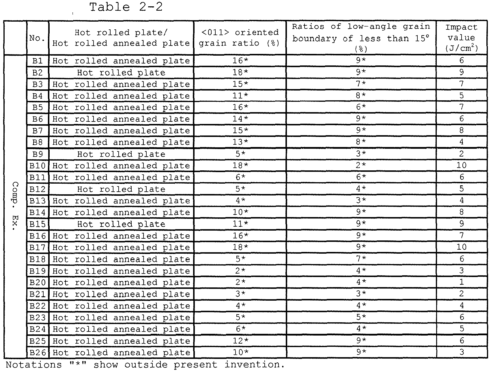
- Table 2-1 and Table 2-2 show the results. In Table 2-2, the notation "*" shows outside the present invention. Further, "the ratio of the low-angle grain boundary of less than 15°" is the ratio of sum of the length of the low-angle grain boundary having a difference in crystal orientation of less than 15° at the cross-section at which the <011> oriented grain ratio was measured and the sum of the length of the crystal grain boundaries at the cross-section.
- The Invention Examples A1 to A20 are hot rolled plates or hot rolled annealed steel sheets having the components of the present invention and produced by the method of production of the present invention. The Invention Examples A1 to A20 all have <011> oriented grain ratios of 20% or more, have ratios of the low-angle grain boundary of less than 15° of 10% or more, and impact values at 0°C of 11J/cm2 or more. If steel having an impact values at 0°C of 7J/cm2 or more, brittle fracture does not occur when the hot rolled coil is uncoiled and the plate is run, so it will be understood that the rolled ferritic stainless steel sheet of the present invention has sufficient toughness. As opposed to this, Comparative Examples B1 to B26 are hot rolled plates or hot rolled annealed steel sheets having some of the components outside the scope of the present invention. Comparative Examples B1 to B26 have <011> oriented grain ratios of less than 20%, ratios of the low-angle grain boundary of less than 15° of less than 10%, and impact values at 0°C failing to reach 7J/cm2 in many cases.
- The steels having the components of the present invention were used to manufacture coils while changing the hot rolling conditions and the annealing conditions as shown in Table 3. The results of evaluation are shown. The notations shown in the column of "Steel No." of Table 3 correspond to the numbers of the steel sheets shown in the "No." column of Table 1. That is, the steel sheets shown in Table 3 have the same compositions as the steel sheets of the corresponding numbers of Table 1 corresponding to the numbers shown in the "Steel No." column of Table 3 and were produced by the methods of production described in Table 3. The steel sheets of Invention Examples C1 to C24 of Table 3 are produced by the manufacturing conditions of the present invention and have excellent toughness. On the other hand, the steel sheets of Comparative Examples D1 to D6 have some of the manufacturing conditions outside the scope of the present invention. The <011> oriented grain ratios are less than 20%, the ratios of the low-angle grain boundary of less than 15° are less than 10%, and the impact values at 0°C fail to reach 7J/cm2.
- Further, the steel sheets of the Invention Examples C1 to C24 and the steel sheets of Comparative Examples D1 to D6 were used as materials to produce
flange parts 1 of shapes symmetric to the left and right as shown inFIG. 2 . Eachflange part 1 was provided with ahole 11 having an inside diameter of a diameter of 55 mm at center thereof and holes 12 for passing bolts and other fastening hardware at the left and right of thehole 11. Above and below thehole 11, thethinnest edge parts hole 11. Further, the ratio of the inside diameter of thehole 11 to the short axis of theoval 5 circumscribing the flange part was 0.65, while the ratio of the thickness of theedge parts oval 5 was 0.18 in each case. - The
flange part 1 was tested by a low temperature drop weight test using the low temperature dropweight test apparatus 2 shown inFIG. 3 . The low temperature drop weight test was conducted using the dropweight test apparatus 2. First, aflange part 1 cooled to -20°C was stood up and fastened on a fastening table 4 so that thethinnest parts weight 3 of 16 kg was freely dropped on the side surface of thethin part 11a from aheight 80 cm and the presence of any cracks of theflange part 1 was visually examined. In this case, the energy given to the flange part became 125J. The flange part was cooled to -20°C using a temperature and humidity testing chamber or using alcohol and liquid nitrogen to adjust the temperature, the sample was held at -20°C for 10 minutes, then impact was applied. - The results of the low temperature dropping weight test are shown in Table 3. In Table 3, the notation "*" indicates outside the present invention. From Table 3, it will be understood that the flange parts produced by the Invention Examples C1 to C24 do not crack when given a 125J or less impact energy at -20°C. In this way, according to the present invention, it is possible to provide a flange part excellent in low temperature toughness. As opposed to this, the hot rolled plates or hot rolled annealed plates produced by manufacturing conditions outside the scope of the present invention in Comparative Examples D1 to D6 cracked due to the impact energy and did not have sufficient toughness.

- Note that, the other conditions in the manufacturing apparatus or manufacturing process may be suitably selected. For example, the hot rolling apparatus may be a continuous type tandem mill or reverse type mill. A Steckel mill having a heating device may also be used in the middle of rolling. The slab thickness, hot rolled plate thickness, etc. may also be suitably designed. After hot rolling and coiling, the steel may also be dipped in a water cooling pool. For the pickling after hot rolling or after hot rolling and annealing, the shot blast, bending, brush, or other mechanical descaling method may be suitably selected. For the acid solution, sulfuric acid, nitrofluoric acid, or other existing acid solution may be used. Furthermore, after this, coil grinding, shot blasting, painting, plating, or other various surface treatments may be applied.
- As clear from the above explanation, the rolled ferritic stainless steel material of the present invention is excellent in manufacturability and secures toughness at the time of flange-making and at the time of use. That is, by using the material applying the present invention in particular for an automobile or motorcycle part, reliability is secured and the degree of social contribution can be raised. The invention is extremely beneficial to industry.
-
- 1. flange part
- 2. drop weight test apparatus
- 3. weight
- 4. fastening table
- 11. hole
- 11a, 11b. edge parts
- 5. circumscribing oval
Claims (9)
- A hot-rolled ferritic stainless steel material consisting of, by mass%, C: 0.001 to 0.08%, Si: 0.01 to 1.0%, Mn: 0.01 to 1.0%, P: 0.01 to 0.05%, S: 0.0002 to 0.01%, Cr: 10.0 to 25.0%, N: 0.001 to 0.05%, and
optionally one type or two types or more of Ti: 0.01 to 0.4%, Nb: 0.01 to 0.6%, B: 0.0002 to 0.0030%, Al: 0.005 to 0.3%, Ni: 0.1 to 1%, Mo: 0.1 to 2.0%, Cu: 0.1 to 3.0%, V: 0.05 to 1.0%, Mg: 0.0002 to 0.0030%, Sn: 0.01 to 0.3%, Sb: 0.01 to 0.3%, Zr: 0.01 to 0.1%, Ta: 0.01 to 0.1%, Hf: 0.01 to 0.1%, W: 0.01 to 2.0%, Co: 0.01 to 0.2%, Ca: 0.0001 to 0.0030%, REM: 0.001 to 0.05%, and Ga: 0.0002 to 0.1%,
having a balance of Fe and unavoidable impurities, having a thickness of 5 mm to 20 mm, and having an area ratio of crystal grains with a <011> direction within 15° from a rolling direction of 20% or more in a cross-section parallel to the rolling direction at any location between left and right ends of the steel sheet, wherein in a cross-section parallel to the rolling direction at any location between the left and right ends of the steel sheet, a sum of lengths of low-angle grain boundaries with a crystal misorientation of less than 15° is 10% or more with respect to a sum of lengths of crystal grain boundaries. - A method of production of a hot-rolled ferritic stainless steel material according to claim 1, comprising:smelting molten steel consisting of, by mass%, C: 0.001 to 0.08%, Si: 0.01 to 1.0%, Mn: 0.01 to 1.0%, P: 0.01 to 0.05%, S: 0.0002 to 0.01%, Cr: 10.0 to 25.0%, N: 0.001 to 0.05%, andoptionally one type or two types or more of Ti: 0.01 to 0.4%, Nb: 0.01 to 0.6%, B: 0.0002 to 0.0030%, Al: 0.005 to 0.3%, Ni: 0.1 to 1%, Mo: 0.1 to 2.0%, Cu: 0.1 to 3.0%, V: 0.05 to 1.0%, Mg: 0.0002 to 0.0030%, Sn: 0.01 to 0.3%, Sb: 0.01 to 0.3%, Zr: 0.01 to 0.1%, Ta: 0.01 to 0.1%, Hf: 0.01 to 0.1%, W: 0.01 to 2.0%, Co: 0.01 to 0.2%, Ca: 0.0001 to 0.0030%, REM: 0.001 to 0.05%, and Ga: 0.0002 to 0.1%,and having a balance of Fe and unavoidable impurities,performing a hot rolling process having a hot rolling finishing temperature of 800°C to 900°C, andperforming a coiling process at a coiling temperature of 200°C to 500°C, optionally, after hot rolling, heating by a heating rate of 10°C/sec or more to 800°C to 1000°C, then annealing, then cooling by a cooling rate of 10°C/sec or more,and optionally performing pickling after hot rolling and annealing.
- The hot-rolled ferritic stainless steel material according to claim 1 characterized by being used as a flange part.
- A ferritic stainless steel flange part comprised of a flange part made of the hot-rolled ferritic stainless steel material according to claim 1, wherein an impact energy at -20°C is 125J or more.
- The steel material according to claim 1 wherein the Mn content thereof is 0.01 to 0.5%.
- The steel material according to claim 1 or 5 which is a hot rolled steel sheet or a hot rolled steel strip.
- The method of production according to claim 2 wherein the obtained steel material is a hot rolled steel sheet, a hot rolled steel strip, a hot rolled annealed steel sheet or a hot rolled annealed steel strip.
- A use of the steel material according to any one of claims 1, 5 and 6 as a flange part.
- The use according to claim 8 wherein an impact energy at -20 °C of the flange part is 125J or more.
Applications Claiming Priority (2)
| Application Number | Priority Date | Filing Date | Title |
|---|---|---|---|
| JP2014064779A JP5908936B2 (en) | 2014-03-26 | 2014-03-26 | Ferritic stainless steel sheet for flange, manufacturing method thereof and flange part |
| PCT/JP2015/059470 WO2015147211A1 (en) | 2014-03-26 | 2015-03-26 | Rolled ferritic stainless-steel plate, process for producing same, and flange component |
Publications (3)
| Publication Number | Publication Date |
|---|---|
| EP3124635A1 EP3124635A1 (en) | 2017-02-01 |
| EP3124635A4 EP3124635A4 (en) | 2017-09-06 |
| EP3124635B1 true EP3124635B1 (en) | 2020-12-23 |
Family
ID=54195715
Family Applications (1)
| Application Number | Title | Priority Date | Filing Date |
|---|---|---|---|
| EP15768500.9A Active EP3124635B1 (en) | 2014-03-26 | 2015-03-26 | Rolled ferritic stainless steel sheet, method for producing the same, and flange part |
Country Status (7)
| Country | Link |
|---|---|
| US (2) | US10648053B2 (en) |
| EP (1) | EP3124635B1 (en) |
| JP (1) | JP5908936B2 (en) |
| KR (1) | KR101928636B1 (en) |
| CN (1) | CN106133166B (en) |
| MX (1) | MX391950B (en) |
| WO (1) | WO2015147211A1 (en) |
Families Citing this family (55)
| Publication number | Priority date | Publication date | Assignee | Title |
|---|---|---|---|---|
| JP6295155B2 (en) * | 2014-07-22 | 2018-03-14 | 新日鐵住金ステンレス株式会社 | Ferritic stainless steel, manufacturing method thereof, and heat exchanger using ferritic stainless steel as a member |
| JP6550325B2 (en) * | 2015-11-27 | 2019-07-24 | 日鉄ステンレス株式会社 | Ferritic stainless steel hot rolled steel sheet for flange and method of manufacturing the same |
| KR102267129B1 (en) * | 2016-02-02 | 2021-06-18 | 닛테츠 스테인레스 가부시키가이샤 | Nb-containing ferritic stainless hot-rolled steel sheet and manufacturing method thereof, Nb-containing ferritic stainless cold-rolled stainless steel sheet and manufacturing method thereof |
| RU2728362C2 (en) | 2016-03-24 | 2020-07-29 | Ниппон Стил Стэйнлесс Стил Корпорейшн | Sheet from ti containing ferritic stainless steel having good impact viscosity, as well as a flange |
| JP6022097B1 (en) * | 2016-03-30 | 2016-11-09 | 日新製鋼株式会社 | Ti-containing ferritic stainless steel sheet and manufacturing method |
| JP6261648B2 (en) * | 2016-05-16 | 2018-01-17 | 日新製鋼株式会社 | Ti-containing ferritic stainless steel sheet for exhaust pipe flange parts and manufacturing method |
| JP6418338B2 (en) | 2016-09-02 | 2018-11-07 | Jfeスチール株式会社 | Ferritic stainless steel |
| EP3486347B1 (en) * | 2016-10-17 | 2020-10-21 | JFE Steel Corporation | Hot-rolled and annealed ferritic stainless steel sheet and method for producing same |
| CN106591736B (en) * | 2016-12-13 | 2018-08-21 | 山西太钢不锈钢股份有限公司 | High-strength low straight-chromiun stainless steel and its heat treatment method |
| KR20180068087A (en) * | 2016-12-13 | 2018-06-21 | 주식회사 포스코 | Ferritic stainless steel with improved impact toughness and method of manufacturing the same |
| EP3572544A4 (en) * | 2017-01-19 | 2020-05-20 | Nippon Steel Stainless Steel Corporation | NON-OXIDIZABLE FERRITE-BASED STEEL, AND NON-OXIDIZABLE FERRITE-BASED STEEL FOR AUTOMOTIVE EXHAUST GAS ROUTING ELEMENT |
| MX2019008874A (en) * | 2017-01-26 | 2019-09-18 | Jfe Steel Corp | HOT ROLLED FERRITIC STAINLESS STEEL SHEET AND METHOD FOR THE MANUFACTURE OF THE SAME. |
| JP6820757B2 (en) * | 2017-01-27 | 2021-01-27 | 日鉄ステンレス株式会社 | Ferritic stainless steel sheets for fastening parts with excellent heat resistance, fastening parts, and circular clamps for heat-resistant tubular members |
| ES2883551T3 (en) * | 2017-02-28 | 2021-12-09 | Nippon Steel Corp | Ferritic stainless steel sheet, hot coil and flange member for motor vehicle exhaust system |
| CN110366601B (en) * | 2017-02-28 | 2021-10-22 | 日本制铁株式会社 | Ferritic stainless steel sheets, hot rolled coils and flange components for automotive exhaust systems |
| JP6814678B2 (en) * | 2017-03-30 | 2021-01-20 | 日鉄ステンレス株式会社 | Ferritic stainless steel pipes for thickening pipe ends and ferritic stainless steel pipes for automobile exhaust system parts |
| JP6858056B2 (en) * | 2017-03-30 | 2021-04-14 | 日鉄ステンレス株式会社 | Low specific gravity ferritic stainless steel sheet and its manufacturing method |
| ES2924685T3 (en) * | 2017-04-27 | 2022-10-10 | Jfe Steel Corp | Annealed hot-rolled ferritic stainless steel sheet and method of making the same |
| CN107475597A (en) * | 2017-08-17 | 2017-12-15 | 苏州双金实业有限公司 | A kind of corrosion-resistant stainless steel material |
| KR20190022127A (en) * | 2017-08-25 | 2019-03-06 | 주식회사 포스코 | Ferritic stainless steel with improved impact toughness at low temperature and method of manufacturing the same |
| JP6518961B1 (en) * | 2017-09-29 | 2019-05-29 | Jfeスチール株式会社 | Ferritic stainless hot rolled annealed steel sheet and method for producing the same |
| CN111295458A (en) * | 2017-10-30 | 2020-06-16 | 杰富意钢铁株式会社 | Ferritic stainless steel sheet and method for producing same |
| KR102020511B1 (en) | 2017-12-14 | 2019-09-10 | 주식회사 포스코 | Ferritic stainless steel with excellent impact toughness and manufacturing method thereof |
| CN108342659A (en) * | 2018-01-31 | 2018-07-31 | 江苏理工学院 | A kind of Economic corrosion-resistant ferritic stainless steel and its manufacturing process |
| JP6971184B2 (en) * | 2018-03-27 | 2021-11-24 | 日鉄ステンレス株式会社 | Ferritic stainless steel, its manufacturing method, and fuel cell components |
| JP6937717B2 (en) * | 2018-03-27 | 2021-09-22 | 日鉄ステンレス株式会社 | Ferritic stainless steel sheets and their manufacturing methods, as well as fuel cell components |
| TWI801538B (en) | 2018-03-27 | 2023-05-11 | 日商日鐵不銹鋼股份有限公司 | Ferritic stainless steel, method for producing the same, ferritic stainless steel sheet, method for producing the same, and members for fuel cell |
| JP6937716B2 (en) * | 2018-03-27 | 2021-09-22 | 日鉄ステンレス株式会社 | Ferritic stainless steel sheets and their manufacturing methods, as well as fuel cell components |
| JP7022633B2 (en) * | 2018-03-29 | 2022-02-18 | 日鉄ステンレス株式会社 | Ferritic stainless steel sheets with excellent high-temperature salt damage resistance and automobile exhaust system parts |
| JP6986135B2 (en) * | 2018-03-30 | 2021-12-22 | 日鉄ステンレス株式会社 | Ferritic stainless steel sheets, their manufacturing methods, and ferritic stainless steel members |
| CN112400031B (en) * | 2018-07-18 | 2022-03-01 | 杰富意钢铁株式会社 | Ferritic stainless steel sheet and method for producing the same |
| KR102490247B1 (en) | 2018-07-18 | 2023-01-18 | 제이에프이 스틸 가부시키가이샤 | Ferritic stainless steel sheet and manufacturing method thereof |
| KR102120695B1 (en) * | 2018-08-28 | 2020-06-09 | 주식회사 포스코 | Ferritic stainless steel excellent in pickling property |
| KR102135158B1 (en) * | 2018-09-19 | 2020-07-17 | 주식회사 포스코 | Ferritic stainless steel excellent in workability and high temperature strength and manufacturing method thereof |
| KR102120696B1 (en) * | 2018-09-19 | 2020-06-09 | 주식회사 포스코 | Non-annealed hot-rolled ferritic stainless steel sheet with excellent impact toughness and manufacturing method thereof |
| JP6722741B2 (en) * | 2018-10-16 | 2020-07-15 | 日鉄ステンレス株式会社 | Ferritic stainless steel sheet with excellent magnetic properties |
| KR102173277B1 (en) * | 2018-11-06 | 2020-11-03 | 주식회사 포스코 | Hot-rolled steel sheet with excellent low temperature impact toughness and manufacturing method thereof |
| WO2020130060A1 (en) * | 2018-12-21 | 2020-06-25 | 日鉄ステンレス株式会社 | Cr-based stainless steel having excellent hydrogen embrittlement resistance |
| JP7186601B2 (en) * | 2018-12-21 | 2022-12-09 | 日鉄ステンレス株式会社 | Cr-based stainless steel used as a metal material for high-pressure hydrogen gas equipment |
| CN109355478B (en) * | 2018-12-24 | 2021-02-05 | 东北大学 | B444M2 type ferritic stainless steel with improved high temperature oxidation resistance and preparation method thereof |
| EP3950969A4 (en) * | 2019-03-28 | 2023-04-19 | NIPPON STEEL Stainless Steel Corporation | AUTOMOBILE BRAKE DISCS FERRITIC STAINLESS STEEL SHEET, AUTOMOBILE BRAKE DISC, AND AUTOMOBILE BRAKE DISCS HOT STAMPED ARTICLE |
| CN109913758B (en) * | 2019-03-29 | 2020-08-11 | 东北大学 | Ferritic stainless steel sheet with good high temperature strength and formability and preparation method thereof |
| CN111235474A (en) * | 2020-02-20 | 2020-06-05 | 孙志颜 | A kind of high corrosion-resistant stainless steel and its manufacturing method |
| KR102443422B1 (en) * | 2020-12-09 | 2022-09-16 | 주식회사 포스코 | High-strength ferritic stainless steel with improved corrosion resistance at welds and manufacturing method therefor |
| KR102443423B1 (en) * | 2020-12-09 | 2022-09-16 | 주식회사 포스코 | Ferritic stainless steel with improved intergranular corrosion properties |
| CN113172089B (en) * | 2021-03-31 | 2023-04-07 | 甘肃酒钢集团宏兴钢铁股份有限公司 | Production method of high-carbon martensitic stainless steel steckel mill |
| CN113699444A (en) * | 2021-08-18 | 2021-11-26 | 山西太钢不锈钢股份有限公司 | Manufacturing method for eliminating edge cracks of 410L black-skin steel coil |
| CN114574767A (en) * | 2022-03-11 | 2022-06-03 | 江苏铭展特钢制造有限公司 | High-temperature-resistant stainless steel bar for automobile parts and processing technology thereof |
| JP7734105B2 (en) * | 2022-03-24 | 2025-09-04 | 三菱重工業株式会社 | Structure inspection device and method |
| CN114959485A (en) * | 2022-06-07 | 2022-08-30 | 江阴市龙润法兰有限公司 | Pressure vessel flange and production process thereof |
| CN115927950B (en) * | 2022-07-29 | 2024-01-09 | 江西宝顺昌特种合金制造有限公司 | A kind of carbon-nitrogen-containing high-chromium ferritic stainless steel and its manufacturing method |
| CN115976312B (en) * | 2022-12-28 | 2024-10-18 | 成都先进金属材料产业技术研究院股份有限公司 | Ferritic stainless steel 00Cr17 and heating method thereof |
| CN117286427B (en) * | 2023-09-26 | 2025-09-26 | 南京钢铁股份有限公司 | A 500MPa-grade economical high-strength ferritic stainless steel medium and thick plate and its preparation method |
| CN117187705B (en) * | 2023-10-27 | 2024-03-26 | 上海交通大学 | A heat treatment method for low Cr and high strength and toughness alloys |
| CN117758141A (en) * | 2023-11-30 | 2024-03-26 | 鞍钢联众(广州)不锈钢有限公司 | A kind of 1.4589 stainless steel for high-strength transmission hinge and its production method |
Family Cites Families (17)
| Publication number | Priority date | Publication date | Assignee | Title |
|---|---|---|---|---|
| EP0573343B1 (en) | 1992-06-01 | 1998-02-25 | Sumitomo Metal Industries, Ltd. | Ferritic stainless steel sheets and foils and method for their production |
| JP3990549B2 (en) * | 2001-06-05 | 2007-10-17 | 新日本製鐵株式会社 | High stretch flangeability steel sheet with excellent shape freezing property and method for producing the same |
| CA2422753C (en) | 2000-09-21 | 2007-11-27 | Nippon Steel Corporation | Steel plate excellent in shape freezing property and method for production thereof |
| JP3908954B2 (en) * | 2001-06-05 | 2007-04-25 | 新日本製鐵株式会社 | Ferritic thin steel sheet with excellent shape freezing property and manufacturing method thereof |
| JP4102284B2 (en) * | 2003-10-20 | 2008-06-18 | 新日本製鐵株式会社 | {100} <011> Cold rolled steel sheet manufacturing method with excellent shape freezing property with developed orientation |
| JP4498950B2 (en) * | 2005-02-25 | 2010-07-07 | 新日鐵住金ステンレス株式会社 | Ferritic stainless steel sheet for exhaust parts with excellent workability and manufacturing method thereof |
| JP4740099B2 (en) * | 2006-03-20 | 2011-08-03 | 新日本製鐵株式会社 | High-strength cold-rolled steel sheet and manufacturing method thereof |
| JP2009030078A (en) * | 2007-07-24 | 2009-02-12 | Nippon Steel & Sumikin Stainless Steel Corp | Highly workable ferritic stainless steel sheet with excellent ridging resistance and method for producing the same |
| JP5262029B2 (en) | 2007-09-11 | 2013-08-14 | Jfeスチール株式会社 | Ferritic stainless steel plate with excellent stretch flangeability |
| JP5347316B2 (en) | 2008-04-24 | 2013-11-20 | Jfeスチール株式会社 | Ferritic stainless steel sheet with excellent toughness |
| JP5737951B2 (en) | 2011-01-05 | 2015-06-17 | 日新製鋼株式会社 | Ti-containing ferritic stainless steel hot-rolled coil and manufacturing method |
| JP5737952B2 (en) | 2011-01-05 | 2015-06-17 | 日新製鋼株式会社 | Nb-containing ferritic stainless steel hot rolled coil and manufacturing method |
| JP5712771B2 (en) * | 2011-04-28 | 2015-05-07 | 新日鐵住金株式会社 | Steel sheet with excellent Young's modulus in the direction perpendicular to rolling and method for producing the same |
| US9631265B2 (en) | 2011-05-25 | 2017-04-25 | Nippon Steel | Hot-rolled steel sheet and method for producing same |
| US20140294660A1 (en) | 2011-12-09 | 2014-10-02 | Nippon Steel & Sumikin Stainless Steel Corporation | Hot-rolled ferritic stainless steel sheet with excellent cold cracking resistance and manufacturing process therefor |
| JP5741483B2 (en) * | 2012-02-27 | 2015-07-01 | 新日鐵住金株式会社 | High-strength hot-rolled steel sheet for line pipes with excellent on-site weldability and manufacturing method thereof |
| JP5793459B2 (en) | 2012-03-30 | 2015-10-14 | 新日鐵住金ステンレス株式会社 | Heat-resistant ferritic stainless steel cold-rolled steel sheet excellent in workability, ferritic stainless hot-rolled steel sheet for cold-rolled material, and production method thereof |
-
2014
- 2014-03-26 JP JP2014064779A patent/JP5908936B2/en active Active
-
2015
- 2015-03-26 CN CN201580016237.1A patent/CN106133166B/en active Active
- 2015-03-26 EP EP15768500.9A patent/EP3124635B1/en active Active
- 2015-03-26 US US15/128,891 patent/US10648053B2/en active Active
- 2015-03-26 MX MX2016012221A patent/MX391950B/en unknown
- 2015-03-26 KR KR1020167025642A patent/KR101928636B1/en active Active
- 2015-03-26 WO PCT/JP2015/059470 patent/WO2015147211A1/en not_active Ceased
-
2020
- 2020-03-30 US US16/834,836 patent/US20200232062A1/en not_active Abandoned
Non-Patent Citations (1)
| Title |
|---|
| None * |
Also Published As
| Publication number | Publication date |
|---|---|
| CN106133166B (en) | 2018-10-23 |
| JP2015187290A (en) | 2015-10-29 |
| CN106133166A (en) | 2016-11-16 |
| KR20160123371A (en) | 2016-10-25 |
| MX2016012221A (en) | 2017-01-19 |
| KR101928636B1 (en) | 2018-12-12 |
| US20200232062A1 (en) | 2020-07-23 |
| WO2015147211A1 (en) | 2015-10-01 |
| US10648053B2 (en) | 2020-05-12 |
| EP3124635A1 (en) | 2017-02-01 |
| MX391950B (en) | 2025-03-21 |
| US20170107593A1 (en) | 2017-04-20 |
| JP5908936B2 (en) | 2016-04-26 |
| EP3124635A4 (en) | 2017-09-06 |
Similar Documents
| Publication | Publication Date | Title |
|---|---|---|
| EP3124635B1 (en) | Rolled ferritic stainless steel sheet, method for producing the same, and flange part | |
| EP2617852B1 (en) | High-strength hot-rolled steel sheet having excellent bending workability and method for producing same | |
| KR101602088B1 (en) | Heat-resistant cold rolled ferritic stainless steel sheet, hot rolled ferritic stainless steel sheet for cold rolling raw material, and methods for producing same | |
| KR101479391B1 (en) | Cold rolled steel sheet having excellent shape fixability and method for manufacturing the same | |
| TW201938816A (en) | High strength cold rolled steel sheet and manufacturing method thereof | |
| JP6485549B2 (en) | High strength hot rolled steel sheet | |
| CN112639146A (en) | High-strength steel sheet and method for producing same | |
| EP3018230B9 (en) | Cold-rolled steel sheet, galvanized cold-rolled steel sheet, and method for manufacturing the same | |
| CN113166866B (en) | Hot rolled steel plate | |
| EP2759613B1 (en) | High-tensile-strength hot-rolled steel sheet and method for producing same | |
| JP5020572B2 (en) | High strength thin steel sheet with excellent delayed fracture resistance after forming | |
| EP2765211B1 (en) | High-tensile-strength hot-rolled steel sheet and method for producing same | |
| EP4043595B1 (en) | Cold-rolled steel sheet and method for producing same | |
| CN108495944A (en) | The hot rolled steel plate of ferrite-group stainless steel containing Nb and its manufacturing method and the cold-rolled steel sheet of ferrite-group stainless steel containing Nb and its manufacturing method | |
| WO2008156195A1 (en) | Ferritic stainless steel sheet having excellent corrosion resistance against sulfuric acid, and method for production thereof | |
| EP3342891B1 (en) | Steel sheet | |
| EP3093362B1 (en) | Ferritic stainless steel and method for producing same | |
| EP3875624A1 (en) | Austenitic stainless steel sheet | |
| KR20180104014A (en) | High strength cold rolled steel sheet | |
| JP2017002333A (en) | High strength steel sheet excellent in shape freezing property and manufacturing method therefor | |
| WO2004106571A1 (en) | High strength thin steel sheet excellent in resistance to delayed fracture after forming and method for preparation thereof, and automobile parts requiring strength manufactured from high strength thin steel sheet | |
| EP3346018B1 (en) | Steel sheet | |
| CN107835865B (en) | Ferritic stainless steel hot-rolled steel sheet, hot-rolled annealed sheet, and method for producing the same | |
| EP3896178A1 (en) | Ferritic stainless steel sheet and method for producing same | |
| JP2023085560A (en) | Duplex stainless steel and manufacturing method thereof |
Legal Events
| Date | Code | Title | Description |
|---|---|---|---|
| STAA | Information on the status of an ep patent application or granted ep patent |
Free format text: STATUS: THE INTERNATIONAL PUBLICATION HAS BEEN MADE |
|
| PUAI | Public reference made under article 153(3) epc to a published international application that has entered the european phase |
Free format text: ORIGINAL CODE: 0009012 |
|
| STAA | Information on the status of an ep patent application or granted ep patent |
Free format text: STATUS: REQUEST FOR EXAMINATION WAS MADE |
|
| 17P | Request for examination filed |
Effective date: 20161026 |
|
| AK | Designated contracting states |
Kind code of ref document: A1 Designated state(s): AL AT BE BG CH CY CZ DE DK EE ES FI FR GB GR HR HU IE IS IT LI LT LU LV MC MK MT NL NO PL PT RO RS SE SI SK SM TR |
|
| AX | Request for extension of the european patent |
Extension state: BA ME |
|
| DAV | Request for validation of the european patent (deleted) | ||
| DAX | Request for extension of the european patent (deleted) | ||
| A4 | Supplementary search report drawn up and despatched |
Effective date: 20170809 |
|
| RIC1 | Information provided on ipc code assigned before grant |
Ipc: C22C 38/50 20060101ALI20170803BHEP Ipc: C22C 38/42 20060101ALI20170803BHEP Ipc: C22C 38/04 20060101ALI20170803BHEP Ipc: C22C 38/02 20060101ALI20170803BHEP Ipc: C22C 38/22 20060101ALI20170803BHEP Ipc: C22C 38/60 20060101ALI20170803BHEP Ipc: C22C 38/48 20060101ALI20170803BHEP Ipc: C21D 8/02 20060101ALI20170803BHEP Ipc: C22C 38/06 20060101ALI20170803BHEP Ipc: C22C 38/20 20060101ALI20170803BHEP Ipc: C22C 38/46 20060101ALI20170803BHEP Ipc: C22C 38/00 20060101AFI20170803BHEP Ipc: C22C 38/24 20060101ALI20170803BHEP Ipc: C21D 9/46 20060101ALI20170803BHEP Ipc: C22C 38/18 20060101ALI20170803BHEP Ipc: C22C 38/54 20060101ALI20170803BHEP Ipc: C21D 6/00 20060101ALI20170803BHEP Ipc: C22C 38/40 20060101ALI20170803BHEP Ipc: C22C 38/44 20060101ALI20170803BHEP |
|
| STAA | Information on the status of an ep patent application or granted ep patent |
Free format text: STATUS: EXAMINATION IS IN PROGRESS |
|
| 17Q | First examination report despatched |
Effective date: 20190729 |
|
| RIC1 | Information provided on ipc code assigned before grant |
Ipc: C22C 38/26 20060101ALI20191121BHEP Ipc: C21D 6/00 20060101ALI20191121BHEP Ipc: C22C 38/60 20060101AFI20191121BHEP Ipc: C22C 38/44 20060101ALI20191121BHEP Ipc: C21D 8/02 20060101ALI20191121BHEP Ipc: C22C 38/40 20060101ALI20191121BHEP Ipc: C21D 9/46 20060101ALI20191121BHEP Ipc: C22C 38/20 20060101ALI20191121BHEP Ipc: C22C 38/48 20060101ALI20191121BHEP Ipc: C22C 38/46 20060101ALI20191121BHEP Ipc: C22C 38/32 20060101ALI20191121BHEP Ipc: C22C 38/28 20060101ALI20191121BHEP Ipc: C22C 38/30 20060101ALI20191121BHEP Ipc: F16L 23/032 20060101ALI20191121BHEP Ipc: C22C 38/42 20060101ALI20191121BHEP Ipc: C22C 38/18 20060101ALI20191121BHEP Ipc: C22C 38/54 20060101ALI20191121BHEP Ipc: C22C 38/52 20060101ALI20191121BHEP Ipc: C22C 38/50 20060101ALI20191121BHEP Ipc: C22C 38/00 20060101ALI20191121BHEP |
|
| GRAP | Despatch of communication of intention to grant a patent |
Free format text: ORIGINAL CODE: EPIDOSNIGR1 |
|
| STAA | Information on the status of an ep patent application or granted ep patent |
Free format text: STATUS: GRANT OF PATENT IS INTENDED |
|
| INTG | Intention to grant announced |
Effective date: 20200108 |
|
| GRAS | Grant fee paid |
Free format text: ORIGINAL CODE: EPIDOSNIGR3 |
|
| GRAJ | Information related to disapproval of communication of intention to grant by the applicant or resumption of examination proceedings by the epo deleted |
Free format text: ORIGINAL CODE: EPIDOSDIGR1 |
|
| GRAL | Information related to payment of fee for publishing/printing deleted |
Free format text: ORIGINAL CODE: EPIDOSDIGR3 |
|
| STAA | Information on the status of an ep patent application or granted ep patent |
Free format text: STATUS: EXAMINATION IS IN PROGRESS |
|
| REG | Reference to a national code |
Ref country code: DE Ref legal event code: R079 Ref document number: 602015063846 Country of ref document: DE Free format text: PREVIOUS MAIN CLASS: C22C0038000000 Ipc: C22C0038500000 |
|
| INTC | Intention to grant announced (deleted) | ||
| GRAP | Despatch of communication of intention to grant a patent |
Free format text: ORIGINAL CODE: EPIDOSNIGR1 |
|
| STAA | Information on the status of an ep patent application or granted ep patent |
Free format text: STATUS: GRANT OF PATENT IS INTENDED |
|
| RIC1 | Information provided on ipc code assigned before grant |
Ipc: C22C 38/18 20060101ALI20200623BHEP Ipc: C22C 38/32 20060101ALI20200623BHEP Ipc: C21D 9/46 20060101ALI20200623BHEP Ipc: C22C 38/26 20060101ALI20200623BHEP Ipc: C21D 8/02 20060101ALI20200623BHEP Ipc: C22C 38/52 20060101ALI20200623BHEP Ipc: C22C 38/50 20060101AFI20200623BHEP Ipc: C22C 38/28 20060101ALI20200623BHEP Ipc: C22C 38/30 20060101ALI20200623BHEP Ipc: C21D 6/00 20060101ALI20200623BHEP |
|
| INTG | Intention to grant announced |
Effective date: 20200715 |
|
| RIN1 | Information on inventor provided before grant (corrected) |
Inventor name: HAMADA, JUNICHI Inventor name: ITO, KOJI |
|
| GRAA | (expected) grant |
Free format text: ORIGINAL CODE: 0009210 |
|
| STAA | Information on the status of an ep patent application or granted ep patent |
Free format text: STATUS: THE PATENT HAS BEEN GRANTED |
|
| AK | Designated contracting states |
Kind code of ref document: B1 Designated state(s): AL AT BE BG CH CY CZ DE DK EE ES FI FR GB GR HR HU IE IS IT LI LT LU LV MC MK MT NL NO PL PT RO RS SE SI SK SM TR |
|
| REG | Reference to a national code |
Ref country code: GB Ref legal event code: FG4D |
|
| REG | Reference to a national code |
Ref country code: DE Ref legal event code: R096 Ref document number: 602015063846 Country of ref document: DE |
|
| REG | Reference to a national code |
Ref country code: AT Ref legal event code: REF Ref document number: 1347804 Country of ref document: AT Kind code of ref document: T Effective date: 20210115 |
|
| REG | Reference to a national code |
Ref country code: IE Ref legal event code: FG4D |
|
| PG25 | Lapsed in a contracting state [announced via postgrant information from national office to epo] |
Ref country code: GR Free format text: LAPSE BECAUSE OF FAILURE TO SUBMIT A TRANSLATION OF THE DESCRIPTION OR TO PAY THE FEE WITHIN THE PRESCRIBED TIME-LIMIT Effective date: 20210324 Ref country code: NO Free format text: LAPSE BECAUSE OF FAILURE TO SUBMIT A TRANSLATION OF THE DESCRIPTION OR TO PAY THE FEE WITHIN THE PRESCRIBED TIME-LIMIT Effective date: 20210323 Ref country code: RS Free format text: LAPSE BECAUSE OF FAILURE TO SUBMIT A TRANSLATION OF THE DESCRIPTION OR TO PAY THE FEE WITHIN THE PRESCRIBED TIME-LIMIT Effective date: 20201223 Ref country code: FI Free format text: LAPSE BECAUSE OF FAILURE TO SUBMIT A TRANSLATION OF THE DESCRIPTION OR TO PAY THE FEE WITHIN THE PRESCRIBED TIME-LIMIT Effective date: 20201223 |
|
| REG | Reference to a national code |
Ref country code: AT Ref legal event code: MK05 Ref document number: 1347804 Country of ref document: AT Kind code of ref document: T Effective date: 20201223 |
|
| REG | Reference to a national code |
Ref country code: NL Ref legal event code: MP Effective date: 20201223 |
|
| PG25 | Lapsed in a contracting state [announced via postgrant information from national office to epo] |
Ref country code: BG Free format text: LAPSE BECAUSE OF FAILURE TO SUBMIT A TRANSLATION OF THE DESCRIPTION OR TO PAY THE FEE WITHIN THE PRESCRIBED TIME-LIMIT Effective date: 20210323 Ref country code: SE Free format text: LAPSE BECAUSE OF FAILURE TO SUBMIT A TRANSLATION OF THE DESCRIPTION OR TO PAY THE FEE WITHIN THE PRESCRIBED TIME-LIMIT Effective date: 20201223 Ref country code: LV Free format text: LAPSE BECAUSE OF FAILURE TO SUBMIT A TRANSLATION OF THE DESCRIPTION OR TO PAY THE FEE WITHIN THE PRESCRIBED TIME-LIMIT Effective date: 20201223 |
|
| PG25 | Lapsed in a contracting state [announced via postgrant information from national office to epo] |
Ref country code: NL Free format text: LAPSE BECAUSE OF FAILURE TO SUBMIT A TRANSLATION OF THE DESCRIPTION OR TO PAY THE FEE WITHIN THE PRESCRIBED TIME-LIMIT Effective date: 20201223 Ref country code: HR Free format text: LAPSE BECAUSE OF FAILURE TO SUBMIT A TRANSLATION OF THE DESCRIPTION OR TO PAY THE FEE WITHIN THE PRESCRIBED TIME-LIMIT Effective date: 20201223 |
|
| REG | Reference to a national code |
Ref country code: LT Ref legal event code: MG9D |
|
| PG25 | Lapsed in a contracting state [announced via postgrant information from national office to epo] |
Ref country code: PT Free format text: LAPSE BECAUSE OF FAILURE TO SUBMIT A TRANSLATION OF THE DESCRIPTION OR TO PAY THE FEE WITHIN THE PRESCRIBED TIME-LIMIT Effective date: 20210423 Ref country code: SK Free format text: LAPSE BECAUSE OF FAILURE TO SUBMIT A TRANSLATION OF THE DESCRIPTION OR TO PAY THE FEE WITHIN THE PRESCRIBED TIME-LIMIT Effective date: 20201223 Ref country code: RO Free format text: LAPSE BECAUSE OF FAILURE TO SUBMIT A TRANSLATION OF THE DESCRIPTION OR TO PAY THE FEE WITHIN THE PRESCRIBED TIME-LIMIT Effective date: 20201223 Ref country code: LT Free format text: LAPSE BECAUSE OF FAILURE TO SUBMIT A TRANSLATION OF THE DESCRIPTION OR TO PAY THE FEE WITHIN THE PRESCRIBED TIME-LIMIT Effective date: 20201223 Ref country code: SM Free format text: LAPSE BECAUSE OF FAILURE TO SUBMIT A TRANSLATION OF THE DESCRIPTION OR TO PAY THE FEE WITHIN THE PRESCRIBED TIME-LIMIT Effective date: 20201223 Ref country code: EE Free format text: LAPSE BECAUSE OF FAILURE TO SUBMIT A TRANSLATION OF THE DESCRIPTION OR TO PAY THE FEE WITHIN THE PRESCRIBED TIME-LIMIT Effective date: 20201223 |
|
| PG25 | Lapsed in a contracting state [announced via postgrant information from national office to epo] |
Ref country code: AT Free format text: LAPSE BECAUSE OF FAILURE TO SUBMIT A TRANSLATION OF THE DESCRIPTION OR TO PAY THE FEE WITHIN THE PRESCRIBED TIME-LIMIT Effective date: 20201223 Ref country code: PL Free format text: LAPSE BECAUSE OF FAILURE TO SUBMIT A TRANSLATION OF THE DESCRIPTION OR TO PAY THE FEE WITHIN THE PRESCRIBED TIME-LIMIT Effective date: 20201223 |
|
| REG | Reference to a national code |
Ref country code: DE Ref legal event code: R097 Ref document number: 602015063846 Country of ref document: DE |
|
| PG25 | Lapsed in a contracting state [announced via postgrant information from national office to epo] |
Ref country code: IS Free format text: LAPSE BECAUSE OF FAILURE TO SUBMIT A TRANSLATION OF THE DESCRIPTION OR TO PAY THE FEE WITHIN THE PRESCRIBED TIME-LIMIT Effective date: 20210423 |
|
| PG25 | Lapsed in a contracting state [announced via postgrant information from national office to epo] |
Ref country code: AL Free format text: LAPSE BECAUSE OF FAILURE TO SUBMIT A TRANSLATION OF THE DESCRIPTION OR TO PAY THE FEE WITHIN THE PRESCRIBED TIME-LIMIT Effective date: 20201223 Ref country code: IT Free format text: LAPSE BECAUSE OF FAILURE TO SUBMIT A TRANSLATION OF THE DESCRIPTION OR TO PAY THE FEE WITHIN THE PRESCRIBED TIME-LIMIT Effective date: 20201223 Ref country code: MC Free format text: LAPSE BECAUSE OF FAILURE TO SUBMIT A TRANSLATION OF THE DESCRIPTION OR TO PAY THE FEE WITHIN THE PRESCRIBED TIME-LIMIT Effective date: 20201223 |
|
| PLBE | No opposition filed within time limit |
Free format text: ORIGINAL CODE: 0009261 |
|
| REG | Reference to a national code |
Ref country code: CH Ref legal event code: PL |
|
| STAA | Information on the status of an ep patent application or granted ep patent |
Free format text: STATUS: NO OPPOSITION FILED WITHIN TIME LIMIT |
|
| PG25 | Lapsed in a contracting state [announced via postgrant information from national office to epo] |
Ref country code: DK Free format text: LAPSE BECAUSE OF FAILURE TO SUBMIT A TRANSLATION OF THE DESCRIPTION OR TO PAY THE FEE WITHIN THE PRESCRIBED TIME-LIMIT Effective date: 20201223 Ref country code: ES Free format text: LAPSE BECAUSE OF FAILURE TO SUBMIT A TRANSLATION OF THE DESCRIPTION OR TO PAY THE FEE WITHIN THE PRESCRIBED TIME-LIMIT Effective date: 20201223 |
|
| 26N | No opposition filed |
Effective date: 20210924 |
|
| REG | Reference to a national code |
Ref country code: BE Ref legal event code: MM Effective date: 20210331 |
|
| PG25 | Lapsed in a contracting state [announced via postgrant information from national office to epo] |
Ref country code: CH Free format text: LAPSE BECAUSE OF NON-PAYMENT OF DUE FEES Effective date: 20210331 Ref country code: LI Free format text: LAPSE BECAUSE OF NON-PAYMENT OF DUE FEES Effective date: 20210331 Ref country code: LU Free format text: LAPSE BECAUSE OF NON-PAYMENT OF DUE FEES Effective date: 20210326 Ref country code: IE Free format text: LAPSE BECAUSE OF NON-PAYMENT OF DUE FEES Effective date: 20210326 |
|
| PG25 | Lapsed in a contracting state [announced via postgrant information from national office to epo] |
Ref country code: SI Free format text: LAPSE BECAUSE OF FAILURE TO SUBMIT A TRANSLATION OF THE DESCRIPTION OR TO PAY THE FEE WITHIN THE PRESCRIBED TIME-LIMIT Effective date: 20201223 |
|
| PG25 | Lapsed in a contracting state [announced via postgrant information from national office to epo] |
Ref country code: IS Free format text: LAPSE BECAUSE OF FAILURE TO SUBMIT A TRANSLATION OF THE DESCRIPTION OR TO PAY THE FEE WITHIN THE PRESCRIBED TIME-LIMIT Effective date: 20210423 |
|
| PG25 | Lapsed in a contracting state [announced via postgrant information from national office to epo] |
Ref country code: BE Free format text: LAPSE BECAUSE OF NON-PAYMENT OF DUE FEES Effective date: 20210331 |
|
| REG | Reference to a national code |
Ref country code: DE Ref legal event code: R081 Ref document number: 602015063846 Country of ref document: DE Owner name: NIPPON STEEL STAINLESS STEEL CORPORATION, JP Free format text: FORMER OWNER: NIPPON STEEL & SUMIKIN STAINLESS STEEL CORPORATION, TOKYO, JP Ref country code: DE Ref legal event code: R081 Ref document number: 602015063846 Country of ref document: DE Owner name: NIPPON STEEL STAINLESS STEEL CORPORATION, TOKY, JP Free format text: FORMER OWNER: NIPPON STEEL & SUMIKIN STAINLESS STEEL CORPORATION, TOKYO, JP |
|
| REG | Reference to a national code |
Ref country code: DE Ref legal event code: R081 Ref document number: 602015063846 Country of ref document: DE Owner name: NIPPON STEEL STAINLESS STEEL CORPORATION, JP Free format text: FORMER OWNER: NIPPON STEEL STAINLESS STEEL CORPORATION, TOKYO, CHIYODA-KU, JP |
|
| PG25 | Lapsed in a contracting state [announced via postgrant information from national office to epo] |
Ref country code: HU Free format text: LAPSE BECAUSE OF FAILURE TO SUBMIT A TRANSLATION OF THE DESCRIPTION OR TO PAY THE FEE WITHIN THE PRESCRIBED TIME-LIMIT; INVALID AB INITIO Effective date: 20150326 |
|
| PG25 | Lapsed in a contracting state [announced via postgrant information from national office to epo] |
Ref country code: CY Free format text: LAPSE BECAUSE OF FAILURE TO SUBMIT A TRANSLATION OF THE DESCRIPTION OR TO PAY THE FEE WITHIN THE PRESCRIBED TIME-LIMIT Effective date: 20201223 |
|
| PG25 | Lapsed in a contracting state [announced via postgrant information from national office to epo] |
Ref country code: MK Free format text: LAPSE BECAUSE OF FAILURE TO SUBMIT A TRANSLATION OF THE DESCRIPTION OR TO PAY THE FEE WITHIN THE PRESCRIBED TIME-LIMIT Effective date: 20201223 |
|
| PG25 | Lapsed in a contracting state [announced via postgrant information from national office to epo] |
Ref country code: MT Free format text: LAPSE BECAUSE OF FAILURE TO SUBMIT A TRANSLATION OF THE DESCRIPTION OR TO PAY THE FEE WITHIN THE PRESCRIBED TIME-LIMIT Effective date: 20201223 |
|
| PGFP | Annual fee paid to national office [announced via postgrant information from national office to epo] |
Ref country code: CZ Payment date: 20250321 Year of fee payment: 11 |
|
| PGFP | Annual fee paid to national office [announced via postgrant information from national office to epo] |
Ref country code: GB Payment date: 20250314 Year of fee payment: 11 |
|
| PGFP | Annual fee paid to national office [announced via postgrant information from national office to epo] |
Ref country code: TR Payment date: 20250210 Year of fee payment: 11 |
|
| PGFP | Annual fee paid to national office [announced via postgrant information from national office to epo] |
Ref country code: DE Payment date: 20260128 Year of fee payment: 12 |
|
| PGFP | Annual fee paid to national office [announced via postgrant information from national office to epo] |
Ref country code: FR Payment date: 20260209 Year of fee payment: 12 |