EP3121090A1 - Luftfederanordnung für schienenfahrzeug und schienenfahrzeug mit luftfederanordnung - Google Patents
Luftfederanordnung für schienenfahrzeug und schienenfahrzeug mit luftfederanordnung Download PDFInfo
- Publication number
- EP3121090A1 EP3121090A1 EP16180567.6A EP16180567A EP3121090A1 EP 3121090 A1 EP3121090 A1 EP 3121090A1 EP 16180567 A EP16180567 A EP 16180567A EP 3121090 A1 EP3121090 A1 EP 3121090A1
- Authority
- EP
- European Patent Office
- Prior art keywords
- compressed air
- air tank
- connection
- tank
- air spring
- Prior art date
- Legal status (The legal status is an assumption and is not a legal conclusion. Google has not performed a legal analysis and makes no representation as to the accuracy of the status listed.)
- Granted
Links
Images


Classifications
-
- B—PERFORMING OPERATIONS; TRANSPORTING
- B61—RAILWAYS
- B61F—RAIL VEHICLE SUSPENSIONS, e.g. UNDERFRAMES, BOGIES OR ARRANGEMENTS OF WHEEL AXLES; RAIL VEHICLES FOR USE ON TRACKS OF DIFFERENT WIDTH; PREVENTING DERAILING OF RAIL VEHICLES; WHEEL GUARDS, OBSTRUCTION REMOVERS OR THE LIKE FOR RAIL VEHICLES
- B61F5/00—Constructional details of bogies; Connections between bogies and vehicle underframes; Arrangements or devices for adjusting or allowing self-adjustment of wheel axles or bogies when rounding curves
- B61F5/02—Arrangements permitting limited transverse relative movements between vehicle underframe or bolster and bogie; Connections between underframes and bogies
- B61F5/04—Bolster supports or mountings
- B61F5/10—Bolster supports or mountings incorporating fluid springs
Definitions
- the invention relates to an air spring arrangement for the suspension of a rail vehicle, in particular the invention relates to an air spring arrangement for a secondary suspension between the vehicle body and bogie of a rail vehicle.
- a rail vehicle is usually sprung in various ways to increase safety and comfort.
- primary suspension and secondary suspension are usually provided.
- the suspension between the wheelsets and the bogie is taken over by the primary suspension.
- the primary suspension is usually realized by leaf springs, but also by coil springs or rubber springs.
- the secondary suspension is used for the suspension between bogie and car body. This also coil springs, but increasingly air springs are used.
- a secondary suspension for a bogie may include, for example, two air springs.
- the secondary suspension of the Jacob bogie may also include four air springs.
- the secondary suspension usually has so-called additional volumes, which are connected via connecting lines with the actual air spring volume.
- additional air volumes When connecting one additional air volume to one air spring, two additional air tanks and corresponding supply lines are used. These additional air volumes serve to increase the compressible air volume of the air springs and thus the increase in the compliance of the air spring.
- the secondary suspension is designed as an air suspension, wherein the air springs are designed as Torusbälge, which are connected via lines with two separate additional volumes. Between the Torusbälgen and the additional volumes three-way valves are arranged.
- the EP 1 610 995 B1 describes a chassis for a rail vehicle with a wheelset.
- the rail vehicle has a chassis frame supported by a primary suspension on the wheel set and a secondary suspension for supporting a car body on the chassis frame.
- the rail vehicle is equipped with a transverse suspension, wherein the transverse suspension is arranged above the secondary suspension and below the floor of the car body.
- an air suspension arrangement for secondary air suspension is provided between the vehicle body and the bogie of a rail vehicle.
- the air spring arrangement comprises a first connecting line for connecting a first air spring with a compressed air volume and a second connecting line for connecting a second air spring with a compressed air volume.
- the air spring assembly also includes a compressed air reservoir that provides a single compressed air volume, with both the first connection line and the second connection line communicating with the one compressed air volume.
- the single compressed air volume forms a common additional air volume for the two air springs.
- the compressed air tank is typically fastened to the car body or to the bogie of a rail vehicle. In particular, the compressed air tank on the car body or on the bogie of a rail vehicle is replaceable fastened.
- the air spring arrangement according to embodiments of the invention allows by combining both air springs with a common compressed air volume of a compressed air tank, a reduction in the mass of the supply arrangement for the air springs.
- a compressed air tank with only one additional air volume is now provided.
- the ratio of volume to surface is advantageous here, in particular in the case of a larger embodiment of the compressed air tank in comparison to previous compressed air tanks.
- a reduced mass saves not only material costs, but also energy costs during operation of the rail vehicle.
- the one compressed air tank which provides the additional air volume for both springs takes up less space than two separate containers.
- a reduced space requirement allows a more favorable positioning of the container in the railway vehicle, in particular with regard to the position of the air springs. The more favorable positioning can in turn allow a shortening of the connecting lines. Shorter interconnections additionally help reduce the mass of the umbilical.
- the design of the connecting lines between the compressed air tank and air springs can in some embodiments have a symmetrical structure result, which in turn positively affects the manufacturing cost.
- the (in particular replaceable) attachment of the compressed air tank on the car body or on the bogie allows easy replacement of the compressed air tank, for example, with a new compressed air tank during maintenance or with a compressed air tank having a plurality of compressed air volumes.
- the first connection line and the second connection line are in fluid communication with each other.
- the first connection line and the second connection line may be in fluid communication via an orifice or control valve for controlling the flow of air between the first connection line and the second connection line.
- an orifice or control valve for controlling the flow of air between the first connection line and the second connection line.
- a control valve can be controlled easily, reliably and quickly.
- the conduits thus configured can continue to be used, even if, for example, a compressed air tank is used which provides an additional damping function.
- the above-described "fluidic connection" can be realized for example by a compensation line.
- the compensation line may have a reduced diameter and thus at the same time act as a throttle between the first and the second air spring.
- a diaphragm or a control valve can be provided.
- the compressed air tank may, in one example, have a first connection for connecting the first connection line to the compressed air volume and a second connection for connecting the second connection line to the compressed air volume. Both connections can be on the same side of the compressed air tank be arranged. Thus, both connection lines can be provided on one side of the container, resulting in a simpler positioning and assembly of the compressed air tank and the two connecting lines. Also, shorter connections can be realized with the connections on one side of the compressed air tank. Such a container is much easier and better position than two separate containers.
- the compressed air tank on two dished ends wherein the first connection for the first connection line and the second connection for the second supply arrangement may be connected to the same dished bottom with the compressed air tank.
- the design can save manufacturing costs by means of dished bottom, since one of the dished ends can be easily adjusted before assembling the compressed air tank.
- the first connection line and the second connection line can be in fluid communication with each other via a control or throttle valve. Both connecting lines may further have a direct connection to the compressed air volume, i. There is a separate fluidic connections between the common compressed air volume and the first connecting line on the one hand and between the common compressed air volume and the second connecting line on the other hand, each not include the control or throttle valve. In this case, the compressed air tank has its own connection for each connecting line.
- the fluidic connection between the two connecting lines via the control or throttle valve thus represents a bypass for the compressed air, which thus directly, partially or completely depending on the position of the control or throttle valve, between the two air springs can flow via the two connecting lines ,
- the control or throttle valve is not mandatory, but only optional.
- the compressed air tank can also have only one connection for both connecting lines.
- the compressed air tank has a circular cylindrical shape with an outer diameter D, wherein at least one of the two front ends of the compressed air tank is formed by a dished bottom.
- a first connection for connecting the first connecting line to the compressed air volume and a second connection for connecting the second connecting line to the compressed air volume are arranged on the dished bottom in a region with a radius of 0.4 ⁇ D about a longitudinal axis of the compressed air tank.
- the first and second ports may have the same or a different distance to the longitudinal axis of the compressed air tank.
- the position of the connections on the dished bottom can be freely selected in the range with a radius of at least 0.4xD. As a result, a placement of the container is even more variable.
- a two-point control of the air springs is realized with the air spring arrangement.
- the two-point control provides reliable and adequate control of the air springs of the secondary suspension of the rail vehicle, while at the same time the simple and less complex control saves costs and maintenance.
- the air spring arrangement can have one or more further connecting lines, wherein the further connecting line (s) is / are connected to the compressed air volume of the compressed air tank.
- the further connecting line (s) is / are connected to the compressed air volume of the compressed air tank.
- the compressed air tank of an air spring arrangement has a fastening element in order to be able to attach the compressed air tank to a rail vehicle, in particular to a car body or a bogie of a rail vehicle.
- the fastener may be a strap, a loop, a notch, a strap, or the like.
- symmetrical spring pressures in the first air spring and in the second air spring are possible, wherein the symmetrical connection of the additional air volume for both air springs is realized by the air spring assembly described herein without complex control and in a simple manner.
- the compressed air tank has a receptacle in the interior of the compressed air tank, which can receive a partition wall within the compressed air tank for separating two volumes.
- the air spring assembly can be quickly and easily converted to provide more than one volume of air. For example, a separation of two volumes for two connecting lines can influence additional control parameters for the air suspension. In a simultaneous fluid connection between the connecting lines and a damping of the roll of the car body can be realized.
- the receptacle for a partition can have guides, recordings, seals and the like.
- the first connecting line and the second connecting line have a common access to the compressed air volume.
- This embodiment is advantageous on the one hand with respect to the installation situation, since only one connection for both connecting lines has to be taken into account during assembly. On the other hand, this is advantageous in terms of flexibility, since only one connection for both connecting lines allows easy and uncomplicated replacement of either the compressed air tank or the connecting lines.
- a rail vehicle with a secondary suspension between the bogie and the car body of the rail vehicle wherein the secondary suspension per bogie has a first air spring and a second air spring.
- the rail vehicle also has a receptacle for an air spring arrangement according to embodiments described herein.
- the rail vehicle may have a receptacle for the compressed air tank of the air spring arrangement.
- the recording allow attachment of the compressed air tank of the air spring assembly on the car body or on the bogie of the rail vehicle.
- the rail vehicle may take up the accommodation in the form of a formation (eg a corresponding installation space or a trained gap), a fastening device (eg in the form of fastening or tightening straps, fastening or clamping clips, screw connections and the like), and / or a complementary structure provide.
- a rail vehicle is provided with an air spring assembly.
- a method for connecting an additional air volume to air springs of a secondary suspension between the vehicle body and bogie of a rail vehicle comprises providing a first compressed air connection between a compressed air volume of a compressed air tank and a first air spring of a secondary suspension and providing a second compressed air connection between the same compressed air volume of the same compressed air tank and a second air spring of the secondary suspension. Furthermore, the method comprises connecting the first compressed air connection and the second compressed air connection to the compressed air tank. According to one embodiment, providing the first connection line and the second connection line comprises connecting the first connection line and the second connection line to the compressed air tank on the same side of the compressed air tank.
- the described air spring arrangement according to embodiments of the invention can be used in all rail vehicles with a secondary suspension, but also in other vehicles.
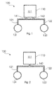
- FIG. 1 shows a schematic drawing of an arrangement for supplying two air springs 131, 132 of a secondary suspension of a rail vehicle.
- the secondary suspension is arranged between the car body and the bogie of a rail vehicle.
- the air springs 131, 132 are connected to an additional air volume 111 in a compressed air tank 110.
- the first air spring 131 is connected by a first connecting line 121 to the compressed air tank 110 and the second air spring 132 by a second connecting line 122 to the same compressed air tank 110.
- the compressed air tank 110 has a single compressed air volume 111, with which the two air springs are connected.
- the compressed air tank meets the safety requirements for pressures from 0 bar to about 10 bar. and is equipped accordingly, for example by a suitable wall thickness, the choice of a suitable material, a suitable attachment of the individual parts of the container and the like.
- a single compressed air volume of the compressed air tank refers to a volume (for example, an additional air volume) for connection to an air spring.
- Subdivisions in the container which serve, for example, the filling, the pressure equalization, the stabilization of the container or the like, are not to be understood in the context of this application as "compressed air volume”.
- the air spring assembly 100 has a port 141 to the compressed air tank 110 to establish the connection between the compressed air tank 110 and the connecting line 121.
- the second connection line 122 is connected by means of connection 142 to the compressed air tank.
- FIG. 1 shows that both connecting lines are connected to one side of the compressed air tank 110. This is particularly favorable with regard to the installation space, since the connection lines can be made relatively short.
- the connecting lines 121 and 122 are also in fluid communication with each other, ie in a connection that allows the Austasuch of fluids between the two connecting lines.
- the connecting pipes 121, 122 are connected to each other and to the compressed air tank by a type of double tee, the double tee containing a shutter.
- the connection between the connection lines, but also the connection lines themselves, can contain orifice or a control valve for regulating the air flow in the connection lines.
- FIG. 2 shows a further embodiment of the inventive air spring assembly 100.
- two air springs 131, 132 are connected to two connecting lines 121, 122.
- the connecting lines 121, 122 are in turn connected to a compressed air tank 110 in order to supply compressed air to the air springs 131, 132 can.
- the two connecting lines 121, 122 have a common connection 140 to the compressed air tank.
- This can be realized for example by a simple T-piece between the connecting lines 121, 122 become.
- the common port 140 increases flexibility, since the space required for the compressed air tank does not depend on whether two ports find space. Also, this simplifies the assembly and maintenance work, since a connection, or replacement of either the connecting lines or the compressed air tank can be done by a single connection step.
- FIG. 3a shows a side view of a compressed air tank 110 for an air spring assembly 100, as shown for example in the Figures 1 and 2 was shown.
- the compressed air tank 110 is formed as a substantially cylindrical body.
- the compressed air tank is composed of a first dished bottom 113, a middle part 116 and a second dished bottom 114.
- the dished bottoms 113 and 114 close the cylindrical body and may, for example, be welded to the central part 116. In another example, the dished bottoms 113, 114 may be secured to the center portion by rivets or similar attachment means.
- the central part 116 of the compressed air tank 110 may be configured as a cylinder.
- the dished bottoms 113 and 114 may have a first portion continuing the cylindrical shape of the center portion 116 and an outwardly bowed or arched second portion.
- the resulting by the composition of the central portion 116 and the dished ends 113 and 114 compressed air tank with a substantially cylindrical shape has a longitudinal axis 115 which extends in the longitudinal direction of the compressed air tank.
- the longitudinal axis 115 may be an axis of symmetry.
- the compressed air tank has a transverse direction 117 which extends in the radial direction of the substantially cylindrical compressed air tank.
- the compressed air tank 110 may also have connections for filling the compressed air tank with compressed air, for example during maintenance.
- the air spring arrangement of air springs and additional air volume can, for example, be fed from outside via one or more supply lines. This supply is controlled by at least one level control valve (usually two per vehicle - therefore 2-point control).
- the compressed air tank can identify seals, which largely prevent escape of compressed air.
- the compressed air tank may also have openings for draining water.
- FIG. 3b showed a front view of the compressed air tank FIG. 3a ,
- the dished bottom 114 is provided with the two terminals 141, 142 for the connecting lines 121, 122, as shown in FIG FIG. 1 is shown.
- the pressure vessel 110 has a diameter D.
- the diameter D of the compressed air tank may be up to about 50 cm.
- the compressed air reservoir may have a total volume of, for example, a volume of about 80 to 100 liters, but also a volume of up to about 200 liters and more
- the two connections 141, 142 are arranged in the vicinity of the longitudinal axis 115 of the compressed air tank 110.
- the ports 141 and 142 may be disposed on the dished bottom in an area having a radius of approximately 0.4 x D about the longitudinal axis 115 of the compressed air tank 110.
- the terminals 141 and 142 are disposed in a 0.4 x D radius region about the longitudinal axis. With respect to the size of the area, a balance between sufficient stability of the compressed air tank and small installation space for the connections, or the connecting lines, can be made in order to determine the optimum range.
- the terminals are spaced from each other.
- the distance between the ports 141 and 142 to the longitudinal axis 115 of the compressed air tank may be the same or different.
- Figure 3c shows a detailed view of the dished bottom 114 and the terminal 141 of the compressed air tank 110.
- the terminal 141 is formed as a part of the dished bottom 114.
- the port 141 may also be formed as part of the first connection line, or may be a separate component that is mounted to the compressed air tank.
- the port 141 may be inserted into a designated bore in the dished bottom 114 and / or welded thereto.
- Figure 3c also shows a tank portion 161 of the first connection pipe 121.
- the tank portion 161 is a portion of the first connection pipe 121 that extends inside the compressed air tank 110. For example, this can improve flow characteristics in the connection lines.
- the container portion 161 is welded to the inside of the dished bottom 114 and the terminal 141. To stabilize a weld on the outside of the compressed air tank between the dished bottom 114 and the terminal 141 is attached.
- FIG. 4a shows a side view of an air spring assembly 100 according to embodiments of the invention.
- FIG. 4b shows a view from the top and from the side of the in the FIG. 4a shown air spring assembly 100.
- the air spring assembly 100 has a compressed air tank 110, which may be, for example, a compressed air tank, as in the FIGS. 3a to 3c shown and described.
- a first connection line 121 is connected to the dished bottom 114 of the compressed air tank 110 via a first connection 141.
- the second connection line 122 is connected to the same dished bottom 114 of the compressed air tank 110 via a second connection 142, which is separate from the first connection 141.
- the dished bottom 113 closes the compressed air tank 110 at the opposite side of the connections 141, 142 for the connecting lines.
- the connecting lines 121 and 122 are fluidly connected to one another via a connection 150.
- the connection 150 may include, for example, a control valve that regulates the flow of air in the connection 150.
- the control valve can be controlled from the outside and to a control mechanism for the air springs (in the FIGS. 4a and 4b not shown).
- the connecting lines themselves can be equipped with orifices or control valves.
- the connection 150 between the connecting lines as can be seen in the FIGS. 4a and 4b can recognize, connecting pieces for the connecting lines 121, 122 have. While the connection lines 121, 122 are merely formed by tubes in the example shown, the connection 150 provides connection pieces into which the tubes can be inserted and fastened. In this case, the connection 150th between the connecting lines 121, 122 also contribute to the stabilization of the air spring assembly 100.
- a fastening element 180 is mounted in the form of a bracket.
- the bracket 180 may be used to secure the air tank 110 to the car body or bogie of the rail vehicle.
- the rail vehicle may have a receptacle in the form of an extension or a spike that can engage the bracket 180 to hold the air tank.
- An additional fixation can be done for example by means of fixing straps and / or screws.
- the fastener 180 allows the compressed air tank or the entire air spring assembly easily replaced, for example, for maintenance purposes. But even a replacement of the compressed air tank with another model of the compressed air tank is so uncomplicated possible.
- the compressed air tank having an air volume according to embodiments described herein may be replaced by a compressed air tank having two or more separate compressed air volumes.
- the air tank can be easily disassembled for upgrading or modification to another model and re-mounted to the car body or bogie after upgrade. An upgrade can be done for example by inserting a partition that makes two separate compressed air volumes in the compressed air tank from the one compressed air volume in the compressed air tank.
- the compressed air tank may already have a receptacle for a partition wall, for example by means of corresponding guides, receptacles and / or fastening means.
Landscapes
- Engineering & Computer Science (AREA)
- Mechanical Engineering (AREA)
- Vehicle Body Suspensions (AREA)
- Fluid-Damping Devices (AREA)
Abstract
Description
- Die Erfindung betrifft eine Luftfederanordnung für die Federung eines Schienenfahrzeugs, insbesondere betrifft die Erfindung eine Luftfederanordnung für eine Sekundärfederung zwischen Wagenkasten und Drehgestell eines Schienenfahrzeugs.
- Ein Schienenfahrzeug wird meist auf verschiedene Arten gefedert, um die Sicherheit und den Komfort zu erhöhen. Für einen hohen Komfort und eine damit verbundene hohe Akzeptanz des Schienenverkehrs bei den Fahrgästen und Lokführern werden meist eine Primärfederung und eine Sekundärfederung zur Verfügung gestellt. Die Federung zwischen den Radsätzen und dem Drehgestell wird von der Primärfederung übernommen. Dabei wird die Primärfederung meist durch Blattfedern, aber auch durch Schraubenfedern oder Gummifedern realisiert.
- Die Sekundärfederung wird für die Federung zwischen Drehgestell und Wagenkasten verwendet. Dabei kommen auch Schraubenfedern, jedoch zunehmend Luftfedern zum Einsatz. Eine Sekundärfederung für ein Drehgestell kann zum Beispiel zwei Luftfedern umfassen. Im Falle eines Jakobsdrehgestells kann die Sekundärfederung des Jakobsdrehgestells auch vier Luftfedern umfassen.
- Die Sekundärfederung weist in der Regel sogenannte Zusatzvolumina auf, welche über Verbindungsleitungen mit den eigentlichen Luftfedervolumen verbunden werden. Bei der Anbindung je eines Zusatzluftvolumens an jeweils eine Luftfeder werden zwei Zusatzluftbehälter und entsprechende Zuleitungen verwendet. Diese Zusatzluftvolumina dienen der Vergrößerung des kompressiblen Luftvolumens der Luftfedern und damit der Erhöhung der Nachgiebigkeit der Luftfeder.
- In der
EP 0 568 043 B1 wird beispielsweise ein Drehgestell für Schienenfahrzeuge mit Primär- und Sekundärfederung beschrieben. Die Sekundärfederung ist dabei als eine Luftfederung ausgebildet, wobei die Luftfedern als Torusbälge ausgeführt sind, die über Leitungen mit zwei getrennten Zusatzvolumina verbunden sind. Zwischen den Torusbälgen und den Zusatzvolumina sind Dreiwegeventile angeordnet. - Die
EP 1 610 995 B1 beschreibt ein Fahrwerk für ein Schienenfahrzeug mit einem Radsatz. Das Schienenfahrzeug weist einen über eine Primärfederung an dem Radsatz abgestützten Fahrwerkrahmen und eine Sekundärfederung zur Abstützung eines Wagenkastens auf dem Fahrwerkrahmen auf. Zusätzlich ist das Schienenfahrzeug mit einer Querfederung ausgestattet, wobei die Querfederung oberhalb der Sekundärfederung und unterhalb des Bodens des Wagenkastens angeordnet ist. - Die obigen Lösungen erfordern eine doppelte Auslegung der Luftfederanordnung hinsichtlich der Zusatzluftvolumina. Dies verursacht jedoch eine erhöhte Masse und einen erhöhten Raumbedarf. Die erhöhte Masse wirkt sich dabei negativ auf die benötigte Energie zum Betreiben des Schienenfahrzeugs aus, während der erhöhte Raumbedarf Schwierigkeiten bei der Unterbringung der Luftfederanordnung oder anderer Komponenten des Schienenfahrzeugs bedeuten kann.
- Es ist daher Aufgabe der vorliegenden Erfindung, eine Luftfederanordnung für eine Sekundärfederung eines Schienenfahrzeugs zur Verfügung zu stellen, die die Systemmasse und den Bauraumbedarf verringert.
- Diese Aufgabe wird gelöst durch eine Luftfederanordnung nach Anspruch 1, ein Schienenfahrzeug nach Anspruch 12 und ein Verfahren zur Anbindung von Zusatzluftvolumina an Luftfedern nach Anspruch 14. Weitere Ausführungsformen, Modifikationen und Verbesserungen ergeben sich anhand der folgenden Beschreibung und der beigefügten Ansprüche.
- Gemäß einer Ausführungsform wird eine Luftfederanordnung für eine sekundäre Luftfederung zwischen Wagenkasten und Drehgestell eines Schienenfahrzeugs zur Verfügung gestellt. Die Luftfederanordnung umfasst eine erste Verbindungsleitung zum Verbinden einer ersten Luftfeder mit einem Druckluftvolumen und eine zweite Verbindungsleitung zum Verbinden einer zweiten Luftfeder mit einem Druckluftvolumen. Die Luftfederanordnung weist außerdem einen Druckluftbehälter auf, der ein einzelnes Druckluftvolumen zur Verfügung stellt, wobei sowohl die erste Verbindungsleitung als auch die zweite Verbindungsleitung mit dem einen Druckluftvolumen in Verbindung stehen. Das einzelne Druckluftvolumen bildet für die beiden Luftfedern ein gemeinsames Zusatzluftvolumen. Der Druckluftbehälter ist typischerweise am Wagenkasten oder am Drehgestell eines Schienenfahrzeugs befestigbar. Insbesondere ist der Druckluftbehälter am Wagenkasten oder am Drehgestell eines Schienenfahrzeugs austauschbar befestigbar.
- Die Luftfederanordnung gemäß Ausführungsformen der Erfindung erlaubt durch das Verbinden beider Luftfedern mit einem gemeinsamen Druckluftvolumen eines Druckluftbehälters eine Reduzierung der Masse der Versorgungsanordnung für die Luftfedern. Anstatt zwei getrennte Druckluftbehälter und zwei getrennte Zusatzluftvolumina für die Erhöhung des kompressiblen Luftvolumens bereit zu stellen, wird nun ein Druckluftbehälter mit nur einem Zusatzluftvolumen bereitgestellt. Insbesondere bei einer im Wesentlichen zylindrischen Ausgestaltung des Druckluftbehälters wirkt dabei das Verhältnis von Volumen zu Oberfläche vorteilhaft, insbesondere bei einer größeren Ausgestaltung des Druckluftbehälters im Vergleich zu bisherigen Druckluftbehältern. Eine reduzierte Masse spart dabei nicht nur Materialkosten, sondern auch Energiekosten beim Betrieb des Schienenfahrzeugs.
- Ein weiterer Vorteil der hierin beschriebenen Luftfederanordnung besteht in dem verringerten Bauraumbedarf. Der eine Druckluftbehälter, der das Zusatzluftvolumen für beide Federn bereitstellt, nimmt weniger Platz ein, als zwei getrennte Behälter. Ein verringerter Bauraumbedarf erlaubt eine günstigere Positionierung des Behälters im Schienenfahrzeug, insbesondere in Bezug auf die Position der Luftfedern. Die günstigere Positionierung kann wiederum eine Verkürzung der Verbindungsleitungen ermöglichen. Kürzere Verbindungsleitungen tragen zusätzlich zur Reduzierung der Masse der Versorgungsanordnung bei. Die Ausgestaltung der Verbindungsleitungen zwischen Druckluftbehälter und Luftfedern kann in einigen Ausführungsformen einen symmetrischen Aufbau zur Folge haben, der wiederum die Herstellungskosten positiv beeinflusst. Die (insbesondere austauschbare) Befestigung des Druckluftbehälters am Wagenkasten oder an dem Drehgestell erlaubt ein einfaches Austauschen des Druckluftbehälters, zum Beispiel mit einem neuen Druckluftbehälter im Rahmen von Wartungsarbeiten oder mit einem Druckluftbehälter, der mehrere Druckluftvolumina aufweist.
- Gemäß einer Ausführungsform stehen die erste Verbindungsleitung und die zweite Verbindungsleitung miteinander in fluidischer Verbindung. Insbesondere können in einer Ausführungsform die erste Verbindungsleitung und die zweite Verbindungsleitung über eine Blende oder ein Regelventil zum Regeln des Luftstroms zwischen der ersten Verbindungsleitung und der zweiten Verbindungsleitung in fluidischer Verbindung stehen. Dadurch können weitere Regelparameter für den Druckluftstrom zu den Luftfedern eingeführt werden. Ein Regelventil lässt sich darüber hinaus einfach, zuverlässig und schnell steuern. Außerdem können die derart ausgestalteten Leitungen, unabhängig von dem verwendeten Druckluftbehälter, weiter verwendet werden, auch wenn zum Beispiel ein Druckluftbehälter verwendet wird, der eine zusätzliche Dämpfungsfunktion bereitstellt.
- Die oben beschriebene "fluidische Verbindung" kann zum Beispiel durch eine Ausgleichsleitung realisiert werden. In einer Ausführungsform kann die Ausgleichsleitung einen reduzierten Durchmesser aufweisen und somit zugleich als Drossel zwischen der ersten und der zweiten Luftfeder wirken. Alternativ oder zusätzlich kann eine Blende oder ein Regelventil vorgesehen werden.
- Der Druckluftbehälter kann in einem Beispiel einen ersten Anschluss für den Anschluss der ersten Verbindungsleitung an das Druckluftvolumen und einen zweiten Anschluss für den Anschluss der zweiten Verbindungsleitung an das Druckluftvolumen aufweisen. Beide Anschlüsse können dabei auf derselben Seite des Druckluftbehälters angeordnet sein. Damit können beide Verbindungsleitungen an einer Seite des Behälters bereitgestellt werden, was zu einer einfacheren Positionierung und Montage des Druckluftbehälters und der beiden Verbindungsleitungen führt. Auch können mit den Anschlüssen an einer Seite des Druckluftbehälters kürzere Verbindungsleitungen realisiert werden. Ein solcher Behälter lässt sich wesentlich einfacher und besser positionieren als zwei separate Behälter.
- Nach einer Ausführungsform der hierin beschriebenen Luftfederanordnung weist der Druckluftbehälter zwei Klöpperböden auf, wobei der erste Anschluss für die erste Verbindungsleitung und der zweite Anschluss für die zweite Versorgungsanordnung an demselben Klöpperboden mit dem Druckluftbehälters verbunden sein können. Neben den oben genannten Vorteilen der Anordnung der beiden Anschlüsse an einer Seite des Druckluftbehälters kann die Ausgestaltung mittels Klöpperboden Herstellungskosten sparen, da einer der Klöpperböden vor dem Zusammensetzen des Druckluftbehälters unkompliziert angepasst werden kann.
- Die erste Verbindungsleitung und die zweite Verbindungsleitung können über ein Regel- oder Drosselventil miteinander in fluidischer Verbindung stehen. Beide Verbindungsleitungen können weiterhin eine direkte Verbindung zum Druckluftvolumen aufweisen, d.h. es besteht eine separate fluidische Verbindungen zwischen dem gemeinsamen Druckluftvolumen und der ersten Verbindungsleitung einerseits und zwischen dem gemeinsamen Druckluftvolumen und der zweiten Verbindungsleitung andererseits, die jeweils nicht das Regel- oder Drosselventil einschließen. In diesem Fall weist der Druckluftbehälter für jede Verbindungsleitung einen eignen Anschluss auf. Die fluidische Verbindung zwischen den beiden Verbindungsleitungen über das Regel- oder Drosselventil stellt demnach einen Bypass für die Druckluft dar, die damit direkt, teilweise oder vollständig in Abhängigkeit von der Stellung des Regel- oder Drosselventils, zwischen den beiden Luftfedern über die beiden Verbindungsleitungen fließen kann. Das Regel- oder Drosselventil ist nicht zwingend erforderlich, sondern nur optional.
- Alternativ kann der Druckluftbehälter auch nur einen Anschluss für beide Verbindungsleitungen aufweisen.
- Gemäß einer Ausführungsform weist der Druckluftbehälter eine kreiszylindrische Form mit einem Außendurchmesser D auf, wobei mindestens eine der beiden Stirnenden des Druckluftbehälters von einem Klöpperboden gebildet wird. Ein erster Anschluss für den Anschluss der ersten Verbindungsleitung an das Druckluftvolumen und ein zweiter Anschluss für den Anschluss der zweiten Verbindungsleitung an das Druckluftvolumen sind am Klöpperboden in einem Bereich mit einem Radius von 0,4 x D um eine Längsachse des Druckluftbehälters angeordnet. Dabei können die ersten und zweiten Anschlüsse einen gleichen oder einen unterschiedlichen Abstand zur Längsachse des Druckluftbehälters aufweisen. Die Position der Anschlüsse am Klöpperboden können in dem Bereich mit einem Radius von mind. 0,4x D frei gewählt werden. Hierdurch ist eine Platzierung des Behälters noch variabler.
- In einer weiteren Ausführungsform wird mit der Luftfederanordnung eine Zwei-Punkt-Regelung der Luftfedern realisiert. Die Zwei-Punkt-Regelung bietet eine zuverlässige und ausreichende Regelung der Luftfedern der Sekundärfederung des Schienenfahrzeugs, wobei gleichzeitig die einfache und wenig komplexe Regelung Kosten und Wartungsarbeiten spart.
- Die Luftfederanordnung kann in einem weiteren Beispiel eine oder mehrere weitere Verbindungsleitung(en) aufweisen, wobei die weitere(n) Verbindungsleitung(en) mit dem Druckluftvolumen des Druckluftbehälter verbunden wird/werden. Damit können zum Beispiel auch drei oder vier Luftfedern (zum Beispiel vier Luftfedern für ein Jakobsdrehgestell) an das eine Druckluftvolumen angeschlossen werden. Dadurch wird die Konstruktion komplexerer Sekundärfederungen vereinfacht und sowohl die Gesamtmasse des Sekundärfederungssystems als auch der benötigte Einbauraum reduziert.
- In einer Ausführungsform weist der Druckluftbehälter einer Luftfederanordnung ein Befestigungselement auf, um den Druckluftbehälter an einem Schienenfahrzeug, insbesondere an einem Wagenkasten oder einem Drehgestell eines Schienenfahrzeugs anbringen zu können. In einem Beispiel kann das Befestigungselement ein Bügel, eine Schlaufe, eine Einkerbung, ein Spannband oder dergleichen sein.
- Gemäß Ausführungsformen der hierin beschriebenen Luftfederanordnung werden symmetrische Federdrücke in der ersten Luftfeder und in der zweiten Luftfeder ermöglicht, wobei die symmetrische Anbindung des Zusatzluftvolumens für beide Luftfedern durch die hierein beschriebene Luftfederanordnung ohne komplexe Regelung und auf einfache Weise realisiert wird.
- In einer Ausführungsform weist der Druckluftbehälter eine Aufnahme im Inneren des Druckluftbehälters auf, die eine Trennwand innerhalb des Druckluftbehälters zum Abtrennen von zwei Volumina aufnehmen kann. Durch das Bereitstellen einer Aufnahme kann die Luftfederanordnung schnell und einfach umgebaut werden, um mehr als ein Luftvolumen zur Verfügung zu stellen. Zum Beispiel können durch eine Abtrennung von zwei Volumina für zwei Verbindungsleitungen zusätzliche Regelparameter für die Luftfederung beeinflusst werden. Bei einer gleichzeitigen Fluidverbindung zwischen den Verbindungsleitungen kann auch eine Dämpfung des Wankens des Wagenkastens realisiert werden. Die Aufnahme für eine Trennwand kann dabei Führungen, Aufnahmen, Dichtungen und dergleichen aufweisen.
- In einer weiteren Ausführungsform der Luftfederanordnung weisen die erste Verbindungsleitung und die zweite Verbindungsleitung einen gemeinsamen Zugang zum Druckluftvolumen auf. Diese Ausgestaltung ist einerseits in Bezug auf die Einbausituation vorteilhaft, da bei der Montage nur ein Anschluss für beide Verbindungsleitungen berücksichtigt werden muss. Andererseits ist dies in Bezug auf die Flexibilität vorteilhaft, da nur ein Anschluss für beide Verbindungsleitungen ein einfaches und unkompliziertes Austauschen entweder des Druckluftbehälters oder der Verbindungsleitungen ermöglicht.
- Gemäß einer Ausführungsform wird ein Schienenfahrzeug mit einer Sekundärfederung zwischen dem Drehgestell und dem Wagenkasten des Schienenfahrzeugs zur Verfügung gestellt, wobei die Sekundärfederung je Drehgestell eine erste Luftfeder und eine zweite Luftfeder aufweist. Das Schienenfahrzeug weist außerdem eine Aufnahme für eine Luftfederanordnung gemäß hierin beschriebenen Ausführungsformen auf. Insbesondere kann das Schienenfahrzeug eine Aufnahme für den Druckluftbehälter der Luftfederanordnung aufweisen. In einem Beispiel kann die Aufnahme eine Befestigung des Druckluftbehälters der Luftfederanordnung am Wagenkasten oder am Drehgestell des Schienenfahrzeugs ermöglichen. Zum Beispiel kann das Schienenfahrzeug die Aufnahme in Form einer Ausformung (z.B. ein entsprechender Einbauraum oder ein ausgebildeter Zwischenraum), einer Befestigungsvorrichtung (z.B. in Form von Befestigungs- oder Spannbändern, Befestigungs- oder Spannschellen, Verschraubungen und dergleichen), und/oder einer komplementären Struktur zur Verfügung stellen. In einer Ausführungsform wird ein Schienenfahrzeug mit einer Luftfederanordnung bereitgestellt.
- In einer weiteren Ausführungsform wird ein Verfahren zur Anbindung eines Zusatzluftvolumens an Luftfedern einer Sekundärfederung zwischen Wagenkasten und Drehgestell eines Schienenfahrzeugs zur Verfügung gestellt. Das Verfahren weist das Bereitstellen einer ersten Druckluftverbindung zwischen einem Druckluftvolumen eines Druckluftbehälters und einer ersten Luftfeder einer Sekundärfederung sowie das Bereitstellen einer zweiten Druckluftverbindung zwischen demselben Druckluftvolumen desselben Druckluftbehälters und einer zweiten Luftfeder der Sekundärfederung auf. Weiterhin umfasst das Verfahren das Verbinden der ersten Druckluftverbindung und der zweiten Druckluftverbindung mit dem Druckluftbehälter.. Gemäß einer Ausführungsform umfasst das Bereitstellen der ersten Verbindungsleitung und der zweiten Verbindungsleitung das Verbinden der ersten Verbindungsleitung und der zweiten Verbindungsleitung mit dem Druckluftbehälter an derselben Seite des Druckluftbehälters.
- Die beschriebene Luftfederanordnung nach Ausführungsformen der Erfindung kann in allen Schienenfahrzeugen mit einer Sekundärfederung, aber auch in anderen Fahrzeugen verwendet werden.
- Die beiliegenden Zeichnungen veranschaulichen Ausführungsformen und dienen zusammen mit der Beschreibung der Erläuterung der Prinzipien der Erfindung. Die Elemente der Zeichnungen sind relativ zueinander und nicht notwendigerweise maßstabsgetreu. Gleiche Bezugszeichen bezeichnen entsprechend ähnliche Teile.
-
Figur 1 zeigt eine Luftfederanordnung mit zwei Luftfedern gemäß einer hierin beschriebenen Ausführungsform. -
Figur 2 zeigt eine Luftfederanordnung mit zwei Luftfedern gemäß einer weiteren, hierin beschriebenen Ausführungsform. -
Figur 3a zeigt eine Seitenansicht eines Druckluftbehälters für eine Luftfederanordnung gemäß hierin beschriebenen Ausführungsformen. -
Figur 3b zeigt eine Vorderansicht des Druckluftbehälters ausFigur 3a . -
Figur 3c zeigt eine Detailansicht des Druckluftbehälters ausFigur 3a . -
Figur 4a zeigt eine Seitenansicht einer Luftfederanordnung nach Ausführungsformen der Erfindung. -
Figur 4b zeigt eine Sicht von oben und von der Seite auf die Luftfederanordnung ausFigur 4a . -
Figur 1 zeigt eine schematische Zeichnung einer Anordnung zur Versorgung von zwei Luftfedern 131, 132 einer Sekundärfederung eines Schienenfahrzeugs. Typischerweise ist die Sekundärfederung zwischen dem Wagenkasten und dem Drehgestell eines Schienenfahrzeugs angeordnet. Die Luftfedern 131, 132 sind mit einem Zusatzluftvolumen 111 in einem Druckluftbehälter 110 verbunden. Dafür ist die erste Luftfeder 131 durch eine erste Verbindungsleitung 121 mit dem Druckluftbehälter 110 und die zweite Luftfeder 132 durch eine zweite Verbindungsleitung 122 mit demselben Druckluftbehälter 110 verbunden. Der Druckluftbehälter 110 weist ein einziges Druckluftvolumen 111 auf, mit dem die zwei Luftfedern verbunden sind. Gemäß Ausführungsformen der Erfindung genügt der Druckluftbehälter den Sicherheitsanforderungen für Drücke von 0 bar bis ungefähr 10 bar. und ist entsprechend ausgestattet, zum Beispiel durch eine geeignete Wandstärke, die Wahl eines geeigneten Materials, eine geeignete Befestigung der Einzelteile des Behälters und dergleichen. - Der Fachmann wird verstehen, dass der Ausdruck "ein einziges Druckluftvolumen" des Druckluftbehälters sich auf ein Volumen (zum Beispiel ein Zusatzluftvolumen) zum Verbinden mit einer Luftfeder bezieht. Unterteilungen in dem Behälter, die zum Beispiel dem Befüllen, dem Druckausgleich, der Stabilisierung des Behälters oder ähnlichem dienen, sind im Rahmen dieser Anmeldung nicht als "Druckluftvolumen" zu verstehen.
- Die Luftfederanordnung 100 weist einen Anschluss 141 an den Druckluftbehälter 110 auf, um die Verbindung zwischen dem Druckluftbehälter 110 und der Verbindungsleitung 121 herzustellen. Die zweite Verbindungsleitung 122 ist mittels Anschluss 142 an den Druckluftbehälter angeschlossen.
Figur 1 zeigt, dass beide Verbindungsleitungen an einer Seite des Druckluftbehälters 110 angeschlossen sind. Dies ist in Hinblick auf den Einbauraum besonders günstig, da die Verbindungsleitungen realtiv kurz gestaltet werden können. - Die Verbindungsleitungen 121 und 122 stehen darüberhinaus auch miteinander in fluidischer Verbindung, d.h. in einer Verbindung, die den Austasuch von Fluiden zwischen den beiden Verbindungsleitungen erlaubt. In dem in
Figur 1 gezeigten Beispiel sind die Verbindungsleitungen 121, 122 durch eine Art Doppel-T-Stück aneinander und an dem Druckluftbehälter angeschlossen, wobei das Doppel-T-Stück eine Blende enthält. Wie später noch im Detail beschrieben werden wird, kann die Verbindung zwischen den Verbindungsleitungen, aber auch die Verbindungsleitungen selber, Blenden oder ein Regelventil zum Regeln des Luftstroms in den Verbindungsleitungen enthalten. -
Figur 2 zeigt eine weitere Ausführungsform der erfindungsgemäßen Luftfederanordnung 100. Wie in derFigur 1 sind auch hier zwei Luftfedern 131, 132 mit zwei Verbindungsleitungen 121, 122verbunden. Die Verbindungsleitungen 121, 122 sind widerum mit einem Druckluftbehälter 110 verbunden, um Druckluft an die Luftfedern 131, 132 liefern zu können. - In dem in
Figur 2 gezeigten Beispiel weisen die beiden Verbindungsleitungen 121, 122 einen gemeinsamen Anschluss 140 zum Druckluftbehälter auf. Dies kann zum Beispiel durch ein einfaches T-Stück zwischen den Verbindungsleitungen 121, 122 realisiert werden. Der gemeinsame Anschluss 140 erhöht die Flexibilität, da der benötigte Bauraum für den Druckluftbehälter nicht davon abhängt, ob zwei Anschlüsse Platz finden. Auch werden dadurch die Montage- und Wartungsarbeiten vereinfacht, da ein Anschluss, bzw. Austausch entweder der Verbindungsleitungen oder des Druckluftbehälters durch einen einzigen Anschlussschritt erfolgen kann. -
Figur 3a zeigt eine Seitenansicht eines Druckluftbehälters 110 für eine Luftfederanordnung 100, wie sie zum Beispiel in denFiguren 1 und 2 gezeigt wurde. Der Druckluftbehälter 110 ist als ein im Wesentlichen zylindrischer Körper ausgebildet. Der Druckluftbehälter setzt sich dabei aus einem ersten Klöpperboden 113, einem Mittelteil 116 und einem zweiten Klöpperboden 114 zusammen. Die Klöpperböden 113 und 114 verschließen den zylindrischen Körper und können zum Beispiel an den Mittelteil 116 angeschweißt sein. In einem anderen Beispiel können die Klöpperböden 113, 114 an dem Mittelteil mittels Nieten oder ähnlichen Befestigungsmitteln befestigt sein. - Der Mittelteil 116 des Druckluftbehälters 110 kann als ein Zylinder ausgestaltet sein. Die Klöpperböden 113 und 114 können einen die Zylinderform des Mittelteils 116 fortführenden ersten Abschnitt und einen nach außen hin gebogenen oder gewölbten zweiten Abschnitt aufweisen. Der durch die Zusammensetzung des Mittelteils 116 und der Klöpperböden 113 und 114 entstandene Druckluftbehälter mit im Wesentlichen zylindrischer Form weist eine Längsachse 115 auf, die in Längsrichtung des Druckluftbehälters verläuft. Insbesondere kann die Längsachse 115 eine Symmetrieachse sein. Außerdem weist der Druckluftbehälter eine Querrichtung 117 auf, die sich in radialer Richtung des im Wesentlichen zylinderförmigen Druckluftbehälters erstreckt.
- Der Druckluftbehälter 110 kann außerdem Anschlüsse aufweisen zum Befüllen des Druckluftbehälters mit Druckluft, zum Beispiel im Rahmen von Wartungsarbeiten. Die Luftfederanordnung aus Luftfedern und Zusatzluftvolumen kann zum Beispiel von außen noch über eine oder mehrere Versorgungsleitungen gespeist werden. Diese Speisung wird von mindestens einem Niveauregulierungsventil geregelt (üblicherweise zwei pro Fahrzeug -daher 2-Punkt Regelung). Außerdem kann der Druckluftbehälter Dichtungen ausweisen, die ein Entweichen der Druckluft weitgehend verhindern. Der Druckluftbehälter kann zudem Öffnungen zum Ablassen von Wasser aufweisen.
-
Figur 3b zeigte eine Vorderansicht des Druckluftbehälters ausFigur 3a . Der Klöpperboden 114 ist mit den beiden Anschlüssen 141, 142 für die Verbindungsleitungen 121, 122 versehen, wie es inFigur 1 gezeigt ist. Dabei zeigtFigur 3b die im Wesentlichen kreisförmige Kontur des Druckbehälters 110. Der Druckbehälter 110 weist einen Durchmesser D auf. In einem Beispiel kann der Durchmesser D des Druckluftbehälters bis ca. 50 cm betragen. Gemäß hierin beschriebener Ausführungsformen kann der Druckluftbehälter insgesamt zum Beispiel ein Volumen von ca. 80 bis 100 Liter, aber auch ein Volumen von bis zu ca. 200 Liter und mehr aufweisen - Die beiden Anschlüsse 141, 142 sind in der Nähe der Längsachse 115 des Druckluftbehälters 110 angeordnet. Insbesondere können die Anschlüsse 141 und 142 am Klöpperboden in einem Bereich mit einem Radius von ungefähr 0,4 x D um die Längsachse 115 des Druckluftbehälters 110 angeordnet sein. In einem Beispiel sind die Anschlüsse 141 und 142 in einem Bereich mit einem Radius von 0,4 x D um die Längsachse angeordnet. Bezüglich der Größe des Bereichs kann eine Abwägung zwischen ausreichender Stabilität des Druckluftbehälters und geringer Einbauraum für die Anschlüsse, bzw. die Verbindungsleitungen, erfolgen, um den optimalen Bereich zu ermitteln.
- Wie die
Figur 3b zeigt, sind die Anschlüsse beabstandet zueinander angeordnet. Dabei kann der Abstand der Anschlüsse 141 und 142 zur Längsachse 115 des Druckluftbehälters gleich oder unterschiedlich sein. -
Figur 3c zeigt eine Detailansicht des Klöpperbodens 114 und des Anschlusses 141 des Druckluftbehälters 110. In dem in derFigur 3c gezeigten Beispiel ist der Anschluss 141 als ein Teil des Klöpperbodens 114 ausgebildet. In anderen Ausführungsformen kann der Anschluss 141 auch als Teil der ersten Verbindungsleitung ausgebildet sein, oder kann ein separates Bauteil sein, das an den Druckluftbehälter montiert ist. Zum Beispiel kann der Anschluss 141 in eine dafür vorgesehene Bohrung in dem Klöpperboden 114 eingeführt werden und/oder daran angeschweißt werden. -
Figur 3c zeigt außerdem einen Behälterabschnitt 161 der ersten Verbindungsleitung 121. Der Behälterabschnitt 161 ist ein Abschnitt der ersten Verbindungsleitung 121, der innerhalb des Druckluftbehälters 110 verläuft. Zum Beispiel können dadurch Strömungseigenschaften in den Verbindungsleitungen verbessert werden. Der Behälterabschnitt 161 ist innen an dem Klöpperboden 114 und dem Anschluss 141 angeschweißt. Zur Stabilisierung ist auch eine Schweißnaht an der Außenseite des Druckluftbehälters zwischen dem Klöpperboden 114 und dem Anschluss 141 angebracht. -
Figur 4a zeigt eine Seitenansicht einer Luftfederanordnung 100 nach Ausführungsformen der Erfindung.Figur 4b zeigt eine Ansicht von oben und von der Seite auf die in derFigur 4a gezeigte Luftfederanordnung 100. Die Luftfederanordnung 100 weist einen Druckluftbehälter 110 auf, der zum Beispiel ein Druckluftbehälter sein kann, wie er in denFiguren 3a bis 3c gezeigt und beschrieben ist. Eine erste Verbindungsleitung 121 ist über einen ersten Anschluss 141 an dem Klöpperboden 114 des Druckluftbehälters 110 angeschlossen. Die zweite Verbindungsleitung 122 ist über einen zweiten, vom ersten Anschluss 141 getrennten Anschluss 142 an denselben Klöpperboden 114 des Druckluftbehälters 110 angeschlossen. Der Klöpperboden 113 verschließt den Druckluftbehälter 110 an der den Anschlüssen 141, 142 für die Verbindungsleitungen gegenüberliegenden Seite. - Die Verbindungsleitungen 121 und 122 sind über eine Verbindung 150 miteinander fluidisch verbunden. Die Verbindung 150 kann zum Beispiel ein Regelventil enthalten, das den Luftstrom in der Verbindung 150 reguliert. Das Regelventil kann von außen angesteuert sein und an einen Kontrollmechanismus für die Luftfedern (in den
Figuren 4a und 4b nicht gezeigt) angeschlossen sein. Auch die Verbindungsleitungen selbst können mit Blenden oder Regelventilen ausgestattet sein. Die Verbindung 150 zwischen den Verbindungsleitungen kann, wie man in denFiguren 4a und 4b erkennen kann, Anschlusstücke für die Verbindungsleitungen 121, 122 aufweisen. Während die Verbindungsleitungen 121, 122 in dem gezeigten Beispiel lediglich durch Rohre gebildet werden, stellt die Verbindung 150 Anschlussstücke zur Verfügung, in die die Rohre eingeführt und durch diese befestigt werden können. Dabei kann die Verbindung 150 zwischen den Verbindungsleitungen 121, 122 auch zur Stabilisierung der Luftfederanordnung 100 beitragen. - An der Außenseite des Druckluftbehälters 110, insbesondere an der Außenseite des Mittelteils 116 des Druckluftbehälters, ist ein Befestigungselement 180 in Form eines Bügels angebracht. Der Bügel 180 kann dafür verwendet werden, den Druckluftbehälter 110 an dem Wagenkasten oder dem Drehgestell des Schienenfahrzeugs zu befestigen. Zum Beispiel kann das Schienenfahrzeug eine Aufnahme in Form einer Verlängerung oder eines Dorns aufweisen, der in den Bügel 180 eingreifen kann, um den Druckluftbehälter zu halten. Eine zusätzliche Fixierung kann zum Beispiel mittels Fixierbändern und/oder Schrauben erfolgen.
- Das Befestigungselement 180 erlaubt es, den Druckluftbehälter oder die ganze Luftfederanordnung einfach auszutauschen, zum Beispiel für Wartungszwecke. Aber auch ein Tausch des Druckluftbehälters mit einem anderen Modell des Druckluftbehälters ist damit unkompliziert möglich. Zum Beispiel kann der Druckluftbehälter mit einem Luftvolumen gemäß hierin beschriebener Ausführungsformen durch einen Druckluftbehälter mit zwei oder mehreren getrennten Druckluftvolumina ersetzt werden. In einem anderen Beispiel kann der Druckluftbehälter zur Aufrüstung oder Modifizierung zu einem anderen Modell einfach demontiert werden und nach der Aufrüstung wieder an den Wagenkasten oder das Drehgestell montiert werden. Eine Aufrüstung kann zum Beispiel durch das Einfügen einer Trennwand erfolgen, die aus dem einen Druckluftvolumen in dem Druckluftbehälter zwei getrennte Druckluftvolumina in dem Druckluftbehälter macht. In einer Ausführungsform kann der Druckluftbehälter bereits eine Aufnahme für eine Trennwand aufweisen, zum Beispiel durch entsprechende Führungen, Aufnahmen und/oder Befestigungsmittel.
-
- 100
- Luftfederanordnung
- 110
- Druckluftbehälter
- 111
- Druckluftvolumen
- 113, 114
- Klöpperböden
- 115
- Längsachse
- 116
- Mittelteil des Druckluftbehälters
- 117
- Querrichtung des Druckluftbehälters
- 121, 122
- Verbindungsleitungen
- 131, 132
- Luftfedern
- 141, 142
- Anschluss an Druckluftbehälter
- 150
- Verbindung der Verbindungsleitungen
- 161
- Behälterabschnitt der Verbindungsleitung
- 180
- Befestigungselement
Claims (15)
- Luftfederanordnung (100) für eine sekundäre Luftfederung zwischen Wagenkasten und Drehgestell eines Schienenfahrzeugs, aufweisend:eine erste Verbindungsleitung (121) zum Verbinden einer ersten Luftfeder (131) mit einem Druckluftvolumen und eine zweite Verbindungsleitung (122) zum Verbinden einer zweiten Luftfeder (132) mit einem Druckluftvolumen;dadurch gekennzeichnet, dass die Luftfederanordnung (100) weiterhin aufweist:einen Druckluftbehälter (110), der ein gemeinsames oder einzelnes Druckluftvolumen (111) zur Verfügung stellt, wobei sowohl die erste Verbindungsleitung (121) als auch die zweite Verbindungsleitung (121) mit dem einen Druckluftvolumen (111) in Verbindung stehen, wobeider Druckluftbehälter (110) am Wagenkasten oder am Drehgestell eines Schienenfahrzeugs befestigbar, insbesondere austauschbar befestigbar, ist.
- Die Luftfederanordnung nach Anspruch 1, wobei die erste Verbindungsleitung (121) und die zweite Verbindungsleitung (122) miteinander in fluidischer Verbindung stehen.
- Die Luftfederanordnung nach einem der vorangehenden Ansprüche, wobei die erste Verbindungsleitung (121) und die zweite Verbindungsleitung (122) über eine Blende oder ein Regelventil (150) zum Regeln des Luftstroms zwischen der ersten Verbindungsleitung und der zweiten Verbindungsleitung in fluidischer Verbindung stehen.
- Die Luftfederanordnung nach einem der vorangehenden Ansprüche, wobei der Druckluftbehälter (110) einen ersten Anschluss (141) für den Anschluss der ersten Verbindungsleitung (121) an das Druckluftvolumen (111) und einen zweiten Anschluss (142) für den Anschluss der zweiten Verbindungsleitung (122) an das Druckluftvolumen (111) aufweist, wobei beide Anschlüsse (141; 142) auf derselben Seite des Druckluftbehälters (110) angeordnet sind.
- Die Luftfederanordnung nach Anspruch 4, wobei der Druckluftbehälter (110) zwei Klöpperböden (113, 114) aufweist und wobei der erste Anschluss (141) und der zweite Anschluss (142) an demselben Klöpperboden (114) mit dem Druckluftbehälters (110) verbunden sind.
- Die Luftfederanordnung nach einem der vorangehenden Ansprüche, wobei der Druckluftbehälter eine kreiszylindrische Form mit einem Außendurchmesser D aufweist und mindestens eine der beiden Stirnenden des Druckluftbehälters von einem Klöpperboden gebildet wird, wobei ein erster Anschluss (141) für den Anschluss der ersten Verbindungsleitung (121) und ein zweiter Anschluss (142) für den Anschluss der zweiten Verbindungsleitung (122) an den Klöpperboden in einem Bereich mit einem Radius von 0, 4 x D um eine Längsachse (115) des Druckluftbehälters (110) angeordnet sind, wobei die ersten und zweiten Anschlüsse (141; 142) einen gleichen oder einen unterschiedlichen Abstand zur Längsachse aufweisen können.
- Die Luftfederanordnung nach einem der vorangehenden Ansprüche, wobei mit der Luftfederanordnung (100) eine Zwei-Punkt-Regelung der Luftfedern (131, 132) realisiert wird.
- Die Luftfederanordnung nach einem der vorangehenden Ansprüche, weiterhin aufweisend eine oder mehrere weitere Verbindungsleitung(en), wobei die weitere(n) Verbindungsleitung(en) mit dem Druckluftvolumen (111) des Druckluftbehälter (110) in Verbindung stehen.
- Die Luftfederanordnung nach einem der vorangehenden Ansprüche, wobei der Druckluftbehälter (110) ein Befestigungselement (180) aufweist zum Befestigen des Druckluftbehälters an einem Schienenfahrzeug, insbesondere an einem Wagenkasten oder Drehgestell eines Schienenfahrzeugs.
- Die Luftfederanordnung nach einem der vorangehenden Ansprüche, wobei der Druckluftbehälter (110) eine Aufnahme im Inneren des Druckluftbehälters aufweist, die eine Trennwand innerhalb des Druckluftbehälters zum Abtrennen von zwei Volumina aufnehmen kann.
- Die Luftfederanordnung nach einem der vorangehenden Ansprüche, wobei die erste Verbindungsleitung (121) und die zweite Verbindungsleitung (122) einen gemeinsamen Anschluss (140) zum gemeinsamen Druckluftvolumen (111) des Druckluftbehälters (110) aufweisen.
- Schienenfahrzeug mit einer Sekundärfederung zwischen dem Drehgestell und dem Wagenkasten des Schienenfahrzeugs, die je Drehgestell eine erste Luftfeder (131) und eine zweite Luftfeder (132) aufweist, wobei das Schienenfahrzeug eine Aufnahme für eine Luftfederanordnung (100) nach einem der vorangehenden Ansprüche aufweist.
- Schienenfahrzeug nach Anspruch 12, wobei die Aufnahme eine Befestigung des Druckluftbehälters (110) der Luftfederanordnung (100) am Wagenkasten oder am Drehgestell des Schienenfahrzeugs ermöglicht.
- Verfahren zum Versorgen von Luftfedern (131; 132) einer Sekundärfederung zwischen Wagenkasten und Drehgestell eines Schienenfahrzeugs, aufweisend:Bereitstellen einer ersten Druckluftverbindung (121) zwischen einem Druckluftvolumen (111) eines Druckluftbehälters (110) und einer ersten Luftfeder (131) einer Sekundärfederung;Bereitstellen einer zweiten Druckluftverbindung (122) zwischen demselben Druckluftvolumen (111) desselben Druckluftbehälters (110) und einer zweiten Luftfeder (131) der Sekundärfederung; undVerbinden der ersten Druckluftverbindung (121) und der zweiten Druckluftverbindung (122) mit dem Druckluftbehälter (110).
- Verfahren nach Anspruch 14, wobei das Bereitstellen der ersten Verbindungsleitung (121) und der zweiten Verbindungsleitung (122) das Verbinden der ersten Verbindungsleitung (121) und der zweiten Verbindungsleitung (122) mit dem Druckluftbehälter (110) an derselben Seite des Druckluftbehälters (110) aufweist.
Applications Claiming Priority (1)
| Application Number | Priority Date | Filing Date | Title |
|---|---|---|---|
| DE102015112015.1A DE102015112015B3 (de) | 2015-07-23 | 2015-07-23 | Luftfederanordnung für schienenfahrzeug und schienenfahrzeug mit luftfederanordnung |
Publications (3)
| Publication Number | Publication Date |
|---|---|
| EP3121090A1 true EP3121090A1 (de) | 2017-01-25 |
| EP3121090B1 EP3121090B1 (de) | 2019-09-04 |
| EP3121090B2 EP3121090B2 (de) | 2025-07-02 |
Family
ID=56507469
Family Applications (1)
| Application Number | Title | Priority Date | Filing Date |
|---|---|---|---|
| EP16180567.6A Active EP3121090B2 (de) | 2015-07-23 | 2016-07-21 | Luftfederanordnung für schienenfahrzeug und schienenfahrzeug mit luftfederanordnung |
Country Status (2)
| Country | Link |
|---|---|
| EP (1) | EP3121090B2 (de) |
| DE (1) | DE102015112015B3 (de) |
Families Citing this family (2)
| Publication number | Priority date | Publication date | Assignee | Title |
|---|---|---|---|---|
| DE102018128858A1 (de) * | 2018-11-16 | 2020-05-20 | Bombardier Transportation Gmbh | Luftfederanordnung für eine Sekundärfederung eines Niederflurschienenfahrzeugs, Wagenkasten und Schienenfahrzeug mit Luftfederanordnung |
| IT202000017020A1 (it) * | 2020-07-14 | 2022-01-14 | Faiveley Transport Italia Spa | Sistema di recupero di aria compressa rilasciata da sospensioni pneumatiche di almeno un veicolo ferroviario o di un convoglio ferroviario |
Citations (6)
| Publication number | Priority date | Publication date | Assignee | Title |
|---|---|---|---|---|
| EP0100513A2 (de) * | 1982-07-30 | 1984-02-15 | Knorr-Bremse Ag | Federung für Losräder von Schienenfahrzeugen |
| JPH0617867A (ja) * | 1992-06-29 | 1994-01-25 | Bridgestone Corp | 高さ調整機構付き空気ばね |
| EP0568043B1 (de) | 1992-04-30 | 1996-04-10 | AEG Schienenfahrzeuge GmbH | Schienenfahrzeug mit Drehgestellen |
| EP1610995B1 (de) | 2003-04-09 | 2007-06-13 | Bombardier Transportation GmbH | Fahrwerk für ein schienenfahrzeug mit verbesserter querfederung |
| DE102009036722A1 (de) * | 2009-08-08 | 2010-03-25 | Daimler Ag | Druckluftbehälter |
| EP2778011A1 (de) * | 2013-03-15 | 2014-09-17 | Bombardier Transportation GmbH | Baugruppe für einen Behälter und Schienenfahrzeug mit einer Baugruppe für einen Behälter |
Family Cites Families (9)
| Publication number | Priority date | Publication date | Assignee | Title |
|---|---|---|---|---|
| US2790650A (en) | 1955-02-22 | 1957-04-30 | Gomma Antivibranti Applic | Pneumatic load-responsive spring suspension for vehicles |
| DE1036072B (de) * | 1955-09-12 | 1958-08-07 | Daimler Benz Ag | Pneumatische Ausgleichsfederung fuer Fahrzeuge |
| DE1214098B (de) * | 1961-07-19 | 1966-04-07 | Italiana Magneti Marelli Soc P | Ausgleichvorrichtung fuer die hoehengleiche Achsenlage zwischen Motorwagen und Anhaenger von Kraftfahrzeugen mit pneumatischer Aufhaengung |
| DE2830359A1 (de) | 1978-07-11 | 1980-01-24 | Knorr Bremse Gmbh | Luftfederung mit niveauregelung fuer fahrzeuge, insbesondere schienenfahrzeuge |
| EP0099597B1 (de) | 1982-07-23 | 1985-12-11 | Werkzeugmaschinenfabrik Oerlikon-Bührle AG | Pneumatische Steuereinrichtung |
| AT407138B (de) * | 1994-09-21 | 2000-12-27 | Siemens Sgp Verkehrstech Gmbh | Laufwerk mit druckbehälter |
| DE102009007674A1 (de) | 2009-02-05 | 2010-08-19 | Knorr-Bremse Systeme für Nutzfahrzeuge GmbH | Niveauregelventil mit je einem Anschluss für Luftfederbälge der rechten und der linken Seite |
| JP4461189B1 (ja) | 2009-02-20 | 2010-05-12 | 三菱重工業株式会社 | 軌道系車両 |
| WO2012132240A1 (ja) | 2011-03-31 | 2012-10-04 | 住友金属工業株式会社 | 鉄道車両の車体傾斜制御方法 |
-
2015
- 2015-07-23 DE DE102015112015.1A patent/DE102015112015B3/de active Active
-
2016
- 2016-07-21 EP EP16180567.6A patent/EP3121090B2/de active Active
Patent Citations (6)
| Publication number | Priority date | Publication date | Assignee | Title |
|---|---|---|---|---|
| EP0100513A2 (de) * | 1982-07-30 | 1984-02-15 | Knorr-Bremse Ag | Federung für Losräder von Schienenfahrzeugen |
| EP0568043B1 (de) | 1992-04-30 | 1996-04-10 | AEG Schienenfahrzeuge GmbH | Schienenfahrzeug mit Drehgestellen |
| JPH0617867A (ja) * | 1992-06-29 | 1994-01-25 | Bridgestone Corp | 高さ調整機構付き空気ばね |
| EP1610995B1 (de) | 2003-04-09 | 2007-06-13 | Bombardier Transportation GmbH | Fahrwerk für ein schienenfahrzeug mit verbesserter querfederung |
| DE102009036722A1 (de) * | 2009-08-08 | 2010-03-25 | Daimler Ag | Druckluftbehälter |
| EP2778011A1 (de) * | 2013-03-15 | 2014-09-17 | Bombardier Transportation GmbH | Baugruppe für einen Behälter und Schienenfahrzeug mit einer Baugruppe für einen Behälter |
Also Published As
| Publication number | Publication date |
|---|---|
| DE102015112015B3 (de) | 2016-09-29 |
| EP3121090B1 (de) | 2019-09-04 |
| EP3121090B2 (de) | 2025-07-02 |
Similar Documents
| Publication | Publication Date | Title |
|---|---|---|
| DE102021202007A1 (de) | Stossdämpfer mit kontinuierlicher dämpfungsregelung | |
| EP0239788A2 (de) | Anordnung zur Gasabscheidung | |
| DE3233160A1 (de) | Vorrichtung zum federn und stabilisieren von fahrzeugen, insbesondere von kraftfahrzeugen | |
| DE102019218022A1 (de) | Fahrzeugschwingungssteuerung durch schaltbare Luftvolumenfederung | |
| CH442413A (de) | Einrichtung an Schienenfahrzeugen zur Abstützung des Fahrzeugoberteils auf den Radgestellen | |
| EP3121090B1 (de) | Luftfederanordnung für schienenfahrzeug und schienenfahrzeug mit luftfederanordnung | |
| WO2016001268A1 (de) | Traeger mit luftausgleichsbehälter | |
| EP3653464B1 (de) | Luftfederanordnung für eine sekundärfederung eines niederflur-schienenfahrzeugs, wagenkasten und schienenfahrzeug mit luftfederanordnung | |
| EP3121089B1 (de) | Luftfederanordnung für schienenfahrzeug und schienenfahrzeug mit luftfederanordnung | |
| EP0040675A2 (de) | Selbstpumpende Niveauregelungsvorrichtung für Fahrzeuge, insbesondere Kraftfahrzeuge | |
| DE202018002498U1 (de) | Druckhaltevorrichtung | |
| DE2656414A1 (de) | Schnellbetriebsbremsvorrichtung fuer druckmittel-fahrzeugbremsanlagen | |
| DE2136732A1 (de) | Vorrichtung zum speichern eines gases in einem loesungsmittel | |
| DE102019008257B4 (de) | Modulare Halterungsvorrichtung zum Montieren eines Gegenstands an einem Fahrzeug, Halteranordnung und Fahrzeug umfassend solch eine Halteranordnung | |
| DE102021214241A1 (de) | Verfahren zum Herstellen einer Abscheidevorrichtung, Verwendung einer Variante eines variablen Wandungselements, Kombination aus mehreren Wandungselementen und Abscheidevorrichtung zum Abscheiden von Flüssigkeit aus einem Fluidstrom | |
| DE102021213990A1 (de) | Kabinenlagerung für ein Nutzfahrzeug sowie Nutzfahrzeug | |
| EP0099597B1 (de) | Pneumatische Steuereinrichtung | |
| DE102020215005A1 (de) | Vorratsbehälter | |
| DE2324340C3 (de) | Vorrichtung zum Einstellen der Neigung von Fahrzeugscheinwerfern | |
| DE102022132720B4 (de) | Verfahren zur Montage eines hydraulischen Dämpfers und System zur Dämpfungsregelung | |
| DE102017130583B3 (de) | Druckflüssigkeitsbereitstellungseinheit | |
| DE3521925A1 (de) | Einrichtung zur automatischen drucksteuerung von luftkissen | |
| DE3140470C2 (de) | Vorrichtung zum Transport von Flüssigkeiten | |
| DE2447795C3 (de) | Vorrichtung zum Steuern des zeitlichen Druckverlaufes in einem Druckluftbehälter | |
| DE1219298B (de) | Vorrichtung zum Zerstaeuben von OEl in druckluftfuehrende Leitungen |
Legal Events
| Date | Code | Title | Description |
|---|---|---|---|
| PUAI | Public reference made under article 153(3) epc to a published international application that has entered the european phase |
Free format text: ORIGINAL CODE: 0009012 |
|
| STAA | Information on the status of an ep patent application or granted ep patent |
Free format text: STATUS: THE APPLICATION HAS BEEN PUBLISHED |
|
| AK | Designated contracting states |
Kind code of ref document: A1 Designated state(s): AL AT BE BG CH CY CZ DE DK EE ES FI FR GB GR HR HU IE IS IT LI LT LU LV MC MK MT NL NO PL PT RO RS SE SI SK SM TR |
|
| AX | Request for extension of the european patent |
Extension state: BA ME |
|
| STAA | Information on the status of an ep patent application or granted ep patent |
Free format text: STATUS: REQUEST FOR EXAMINATION WAS MADE |
|
| RAP1 | Party data changed (applicant data changed or rights of an application transferred) |
Owner name: BOMBARDIER TRANSPORTATION GMBH |
|
| 17P | Request for examination filed |
Effective date: 20170719 |
|
| RBV | Designated contracting states (corrected) |
Designated state(s): AL AT BE BG CH CY CZ DE DK EE ES FI FR GB GR HR HU IE IS IT LI LT LU LV MC MK MT NL NO PL PT RO RS SE SI SK SM TR |
|
| GRAP | Despatch of communication of intention to grant a patent |
Free format text: ORIGINAL CODE: EPIDOSNIGR1 |
|
| STAA | Information on the status of an ep patent application or granted ep patent |
Free format text: STATUS: GRANT OF PATENT IS INTENDED |
|
| INTG | Intention to grant announced |
Effective date: 20181023 |
|
| GRAJ | Information related to disapproval of communication of intention to grant by the applicant or resumption of examination proceedings by the epo deleted |
Free format text: ORIGINAL CODE: EPIDOSDIGR1 |
|
| STAA | Information on the status of an ep patent application or granted ep patent |
Free format text: STATUS: REQUEST FOR EXAMINATION WAS MADE |
|
| GRAP | Despatch of communication of intention to grant a patent |
Free format text: ORIGINAL CODE: EPIDOSNIGR1 |
|
| INTC | Intention to grant announced (deleted) | ||
| STAA | Information on the status of an ep patent application or granted ep patent |
Free format text: STATUS: GRANT OF PATENT IS INTENDED |
|
| INTG | Intention to grant announced |
Effective date: 20190321 |
|
| GRAS | Grant fee paid |
Free format text: ORIGINAL CODE: EPIDOSNIGR3 |
|
| GRAA | (expected) grant |
Free format text: ORIGINAL CODE: 0009210 |
|
| STAA | Information on the status of an ep patent application or granted ep patent |
Free format text: STATUS: THE PATENT HAS BEEN GRANTED |
|
| AK | Designated contracting states |
Kind code of ref document: B1 Designated state(s): AL AT BE BG CH CY CZ DE DK EE ES FI FR GB GR HR HU IE IS IT LI LT LU LV MC MK MT NL NO PL PT RO RS SE SI SK SM TR |
|
| REG | Reference to a national code |
Ref country code: GB Ref legal event code: FG4D Free format text: NOT ENGLISH |
|
| REG | Reference to a national code |
Ref country code: CH Ref legal event code: EP |
|
| REG | Reference to a national code |
Ref country code: AT Ref legal event code: REF Ref document number: 1174945 Country of ref document: AT Kind code of ref document: T Effective date: 20190915 |
|
| REG | Reference to a national code |
Ref country code: DE Ref legal event code: R096 Ref document number: 502016006388 Country of ref document: DE |
|
| REG | Reference to a national code |
Ref country code: IE Ref legal event code: FG4D Free format text: LANGUAGE OF EP DOCUMENT: GERMAN |
|
| REG | Reference to a national code |
Ref country code: CH Ref legal event code: NV Representative=s name: TR-IP CONSULTING LLC, CH |
|
| REG | Reference to a national code |
Ref country code: NL Ref legal event code: MP Effective date: 20190904 |
|
| REG | Reference to a national code |
Ref country code: LT Ref legal event code: MG4D |
|
| PG25 | Lapsed in a contracting state [announced via postgrant information from national office to epo] |
Ref country code: SE Free format text: LAPSE BECAUSE OF FAILURE TO SUBMIT A TRANSLATION OF THE DESCRIPTION OR TO PAY THE FEE WITHIN THE PRESCRIBED TIME-LIMIT Effective date: 20190904 Ref country code: HR Free format text: LAPSE BECAUSE OF FAILURE TO SUBMIT A TRANSLATION OF THE DESCRIPTION OR TO PAY THE FEE WITHIN THE PRESCRIBED TIME-LIMIT Effective date: 20190904 Ref country code: FI Free format text: LAPSE BECAUSE OF FAILURE TO SUBMIT A TRANSLATION OF THE DESCRIPTION OR TO PAY THE FEE WITHIN THE PRESCRIBED TIME-LIMIT Effective date: 20190904 Ref country code: LT Free format text: LAPSE BECAUSE OF FAILURE TO SUBMIT A TRANSLATION OF THE DESCRIPTION OR TO PAY THE FEE WITHIN THE PRESCRIBED TIME-LIMIT Effective date: 20190904 Ref country code: BG Free format text: LAPSE BECAUSE OF FAILURE TO SUBMIT A TRANSLATION OF THE DESCRIPTION OR TO PAY THE FEE WITHIN THE PRESCRIBED TIME-LIMIT Effective date: 20191204 Ref country code: NO Free format text: LAPSE BECAUSE OF FAILURE TO SUBMIT A TRANSLATION OF THE DESCRIPTION OR TO PAY THE FEE WITHIN THE PRESCRIBED TIME-LIMIT Effective date: 20191204 |
|
| REG | Reference to a national code |
Ref country code: CH Ref legal event code: PCAR Free format text: NEW ADDRESS: ROUTE DU COUTSET 18, 1485 NUVILLY (CH) |
|
| PG25 | Lapsed in a contracting state [announced via postgrant information from national office to epo] |
Ref country code: AL Free format text: LAPSE BECAUSE OF FAILURE TO SUBMIT A TRANSLATION OF THE DESCRIPTION OR TO PAY THE FEE WITHIN THE PRESCRIBED TIME-LIMIT Effective date: 20190904 Ref country code: ES Free format text: LAPSE BECAUSE OF FAILURE TO SUBMIT A TRANSLATION OF THE DESCRIPTION OR TO PAY THE FEE WITHIN THE PRESCRIBED TIME-LIMIT Effective date: 20190904 Ref country code: LV Free format text: LAPSE BECAUSE OF FAILURE TO SUBMIT A TRANSLATION OF THE DESCRIPTION OR TO PAY THE FEE WITHIN THE PRESCRIBED TIME-LIMIT Effective date: 20190904 Ref country code: RS Free format text: LAPSE BECAUSE OF FAILURE TO SUBMIT A TRANSLATION OF THE DESCRIPTION OR TO PAY THE FEE WITHIN THE PRESCRIBED TIME-LIMIT Effective date: 20190904 Ref country code: GR Free format text: LAPSE BECAUSE OF FAILURE TO SUBMIT A TRANSLATION OF THE DESCRIPTION OR TO PAY THE FEE WITHIN THE PRESCRIBED TIME-LIMIT Effective date: 20191205 |
|
| PG25 | Lapsed in a contracting state [announced via postgrant information from national office to epo] |
Ref country code: IT Free format text: LAPSE BECAUSE OF FAILURE TO SUBMIT A TRANSLATION OF THE DESCRIPTION OR TO PAY THE FEE WITHIN THE PRESCRIBED TIME-LIMIT Effective date: 20190904 Ref country code: PT Free format text: LAPSE BECAUSE OF FAILURE TO SUBMIT A TRANSLATION OF THE DESCRIPTION OR TO PAY THE FEE WITHIN THE PRESCRIBED TIME-LIMIT Effective date: 20200106 Ref country code: RO Free format text: LAPSE BECAUSE OF FAILURE TO SUBMIT A TRANSLATION OF THE DESCRIPTION OR TO PAY THE FEE WITHIN THE PRESCRIBED TIME-LIMIT Effective date: 20190904 Ref country code: NL Free format text: LAPSE BECAUSE OF FAILURE TO SUBMIT A TRANSLATION OF THE DESCRIPTION OR TO PAY THE FEE WITHIN THE PRESCRIBED TIME-LIMIT Effective date: 20190904 Ref country code: EE Free format text: LAPSE BECAUSE OF FAILURE TO SUBMIT A TRANSLATION OF THE DESCRIPTION OR TO PAY THE FEE WITHIN THE PRESCRIBED TIME-LIMIT Effective date: 20190904 Ref country code: PL Free format text: LAPSE BECAUSE OF FAILURE TO SUBMIT A TRANSLATION OF THE DESCRIPTION OR TO PAY THE FEE WITHIN THE PRESCRIBED TIME-LIMIT Effective date: 20190904 |
|
| REG | Reference to a national code |
Ref country code: DE Ref legal event code: R026 Ref document number: 502016006388 Country of ref document: DE |
|
| PG25 | Lapsed in a contracting state [announced via postgrant information from national office to epo] |
Ref country code: IS Free format text: LAPSE BECAUSE OF FAILURE TO SUBMIT A TRANSLATION OF THE DESCRIPTION OR TO PAY THE FEE WITHIN THE PRESCRIBED TIME-LIMIT Effective date: 20200224 Ref country code: SM Free format text: LAPSE BECAUSE OF FAILURE TO SUBMIT A TRANSLATION OF THE DESCRIPTION OR TO PAY THE FEE WITHIN THE PRESCRIBED TIME-LIMIT Effective date: 20190904 Ref country code: SK Free format text: LAPSE BECAUSE OF FAILURE TO SUBMIT A TRANSLATION OF THE DESCRIPTION OR TO PAY THE FEE WITHIN THE PRESCRIBED TIME-LIMIT Effective date: 20190904 Ref country code: CZ Free format text: LAPSE BECAUSE OF FAILURE TO SUBMIT A TRANSLATION OF THE DESCRIPTION OR TO PAY THE FEE WITHIN THE PRESCRIBED TIME-LIMIT Effective date: 20190904 |
|
| PLBI | Opposition filed |
Free format text: ORIGINAL CODE: 0009260 |
|
| PLAX | Notice of opposition and request to file observation + time limit sent |
Free format text: ORIGINAL CODE: EPIDOSNOBS2 |
|
| 26 | Opposition filed |
Opponent name: SIEMENS MOBILITY GMBH Effective date: 20200526 |
|
| PG2D | Information on lapse in contracting state deleted |
Ref country code: IS |
|
| PG25 | Lapsed in a contracting state [announced via postgrant information from national office to epo] |
Ref country code: DK Free format text: LAPSE BECAUSE OF FAILURE TO SUBMIT A TRANSLATION OF THE DESCRIPTION OR TO PAY THE FEE WITHIN THE PRESCRIBED TIME-LIMIT Effective date: 20190904 Ref country code: IS Free format text: LAPSE BECAUSE OF FAILURE TO SUBMIT A TRANSLATION OF THE DESCRIPTION OR TO PAY THE FEE WITHIN THE PRESCRIBED TIME-LIMIT Effective date: 20200105 |
|
| PG25 | Lapsed in a contracting state [announced via postgrant information from national office to epo] |
Ref country code: SI Free format text: LAPSE BECAUSE OF FAILURE TO SUBMIT A TRANSLATION OF THE DESCRIPTION OR TO PAY THE FEE WITHIN THE PRESCRIBED TIME-LIMIT Effective date: 20190904 |
|
| PLBB | Reply of patent proprietor to notice(s) of opposition received |
Free format text: ORIGINAL CODE: EPIDOSNOBS3 |
|
| PG25 | Lapsed in a contracting state [announced via postgrant information from national office to epo] |
Ref country code: MC Free format text: LAPSE BECAUSE OF FAILURE TO SUBMIT A TRANSLATION OF THE DESCRIPTION OR TO PAY THE FEE WITHIN THE PRESCRIBED TIME-LIMIT Effective date: 20190904 |
|
| GBPC | Gb: european patent ceased through non-payment of renewal fee |
Effective date: 20200721 |
|
| REG | Reference to a national code |
Ref country code: BE Ref legal event code: MM Effective date: 20200731 |
|
| PG25 | Lapsed in a contracting state [announced via postgrant information from national office to epo] |
Ref country code: GB Free format text: LAPSE BECAUSE OF NON-PAYMENT OF DUE FEES Effective date: 20200721 Ref country code: LU Free format text: LAPSE BECAUSE OF NON-PAYMENT OF DUE FEES Effective date: 20200721 |
|
| PG25 | Lapsed in a contracting state [announced via postgrant information from national office to epo] |
Ref country code: BE Free format text: LAPSE BECAUSE OF NON-PAYMENT OF DUE FEES Effective date: 20200731 |
|
| PG25 | Lapsed in a contracting state [announced via postgrant information from national office to epo] |
Ref country code: IE Free format text: LAPSE BECAUSE OF NON-PAYMENT OF DUE FEES Effective date: 20200721 |
|
| APBM | Appeal reference recorded |
Free format text: ORIGINAL CODE: EPIDOSNREFNO |
|
| APBP | Date of receipt of notice of appeal recorded |
Free format text: ORIGINAL CODE: EPIDOSNNOA2O |
|
| APAH | Appeal reference modified |
Free format text: ORIGINAL CODE: EPIDOSCREFNO |
|
| PG25 | Lapsed in a contracting state [announced via postgrant information from national office to epo] |
Ref country code: TR Free format text: LAPSE BECAUSE OF FAILURE TO SUBMIT A TRANSLATION OF THE DESCRIPTION OR TO PAY THE FEE WITHIN THE PRESCRIBED TIME-LIMIT Effective date: 20190904 Ref country code: MT Free format text: LAPSE BECAUSE OF FAILURE TO SUBMIT A TRANSLATION OF THE DESCRIPTION OR TO PAY THE FEE WITHIN THE PRESCRIBED TIME-LIMIT Effective date: 20190904 Ref country code: CY Free format text: LAPSE BECAUSE OF FAILURE TO SUBMIT A TRANSLATION OF THE DESCRIPTION OR TO PAY THE FEE WITHIN THE PRESCRIBED TIME-LIMIT Effective date: 20190904 |
|
| APBM | Appeal reference recorded |
Free format text: ORIGINAL CODE: EPIDOSNREFNO |
|
| APBP | Date of receipt of notice of appeal recorded |
Free format text: ORIGINAL CODE: EPIDOSNNOA2O |
|
| PG25 | Lapsed in a contracting state [announced via postgrant information from national office to epo] |
Ref country code: MK Free format text: LAPSE BECAUSE OF FAILURE TO SUBMIT A TRANSLATION OF THE DESCRIPTION OR TO PAY THE FEE WITHIN THE PRESCRIBED TIME-LIMIT Effective date: 20190904 |
|
| APBQ | Date of receipt of statement of grounds of appeal recorded |
Free format text: ORIGINAL CODE: EPIDOSNNOA3O |
|
| APBQ | Date of receipt of statement of grounds of appeal recorded |
Free format text: ORIGINAL CODE: EPIDOSNNOA3O |
|
| PLAB | Opposition data, opponent's data or that of the opponent's representative modified |
Free format text: ORIGINAL CODE: 0009299OPPO |
|
| R26 | Opposition filed (corrected) |
Opponent name: SIEMENS MOBILITY GMBH Effective date: 20200526 |
|
| RAP2 | Party data changed (patent owner data changed or rights of a patent transferred) |
Owner name: ALSTOM HOLDINGS |
|
| P01 | Opt-out of the competence of the unified patent court (upc) registered |
Effective date: 20230822 |
|
| APBU | Appeal procedure closed |
Free format text: ORIGINAL CODE: EPIDOSNNOA9O |
|
| PUAH | Patent maintained in amended form |
Free format text: ORIGINAL CODE: 0009272 |
|
| STAA | Information on the status of an ep patent application or granted ep patent |
Free format text: STATUS: PATENT MAINTAINED AS AMENDED |
|
| 27A | Patent maintained in amended form |
Effective date: 20250702 |
|
| AK | Designated contracting states |
Kind code of ref document: B2 Designated state(s): AL AT BE BG CH CY CZ DE DK EE ES FI FR GB GR HR HU IE IS IT LI LT LU LV MC MK MT NL NO PL PT RO RS SE SI SK SM TR |
|
| REG | Reference to a national code |
Ref country code: DE Ref legal event code: R102 Ref document number: 502016006388 Country of ref document: DE |
|
| PGFP | Annual fee paid to national office [announced via postgrant information from national office to epo] |
Ref country code: DE Payment date: 20250722 Year of fee payment: 10 |
|
| PGFP | Annual fee paid to national office [announced via postgrant information from national office to epo] |
Ref country code: FR Payment date: 20250725 Year of fee payment: 10 Ref country code: AT Payment date: 20250722 Year of fee payment: 10 |
|
| PGFP | Annual fee paid to national office [announced via postgrant information from national office to epo] |
Ref country code: CH Payment date: 20250801 Year of fee payment: 10 |