EP3121015B1 - Vorrichtung und verfahren zum bedrucken von textilen oberflächen - Google Patents
Vorrichtung und verfahren zum bedrucken von textilen oberflächen Download PDFInfo
- Publication number
- EP3121015B1 EP3121015B1 EP15177435.3A EP15177435A EP3121015B1 EP 3121015 B1 EP3121015 B1 EP 3121015B1 EP 15177435 A EP15177435 A EP 15177435A EP 3121015 B1 EP3121015 B1 EP 3121015B1
- Authority
- EP
- European Patent Office
- Prior art keywords
- printing
- textile
- pallet
- station
- pallets
- Prior art date
- Legal status (The legal status is an assumption and is not a legal conclusion. Google has not performed a legal analysis and makes no representation as to the accuracy of the status listed.)
- Active
Links
- 239000004753 textile Substances 0.000 title claims description 61
- 238000000034 method Methods 0.000 title claims description 10
- 238000006073 displacement reaction Methods 0.000 description 1
- 238000002360 preparation method Methods 0.000 description 1
- 239000000725 suspension Substances 0.000 description 1
Images

Classifications
-
- B—PERFORMING OPERATIONS; TRANSPORTING
- B41—PRINTING; LINING MACHINES; TYPEWRITERS; STAMPS
- B41J—TYPEWRITERS; SELECTIVE PRINTING MECHANISMS, i.e. MECHANISMS PRINTING OTHERWISE THAN FROM A FORME; CORRECTION OF TYPOGRAPHICAL ERRORS
- B41J3/00—Typewriters or selective printing or marking mechanisms characterised by the purpose for which they are constructed
- B41J3/407—Typewriters or selective printing or marking mechanisms characterised by the purpose for which they are constructed for marking on special material
- B41J3/4078—Printing on textile
-
- B—PERFORMING OPERATIONS; TRANSPORTING
- B41—PRINTING; LINING MACHINES; TYPEWRITERS; STAMPS
- B41J—TYPEWRITERS; SELECTIVE PRINTING MECHANISMS, i.e. MECHANISMS PRINTING OTHERWISE THAN FROM A FORME; CORRECTION OF TYPOGRAPHICAL ERRORS
- B41J11/00—Devices or arrangements of selective printing mechanisms, e.g. ink-jet printers or thermal printers, for supporting or handling copy material in sheet or web form
- B41J11/02—Platens
- B41J11/06—Flat page-size platens or smaller flat platens having a greater size than line-size platens
-
- B—PERFORMING OPERATIONS; TRANSPORTING
- B41—PRINTING; LINING MACHINES; TYPEWRITERS; STAMPS
- B41J—TYPEWRITERS; SELECTIVE PRINTING MECHANISMS, i.e. MECHANISMS PRINTING OTHERWISE THAN FROM A FORME; CORRECTION OF TYPOGRAPHICAL ERRORS
- B41J11/00—Devices or arrangements of selective printing mechanisms, e.g. ink-jet printers or thermal printers, for supporting or handling copy material in sheet or web form
- B41J11/02—Platens
- B41J11/14—Platen-shift mechanisms; Driving gear therefor
-
- D—TEXTILES; PAPER
- D06—TREATMENT OF TEXTILES OR THE LIKE; LAUNDERING; FLEXIBLE MATERIALS NOT OTHERWISE PROVIDED FOR
- D06P—DYEING OR PRINTING TEXTILES; DYEING LEATHER, FURS OR SOLID MACROMOLECULAR SUBSTANCES IN ANY FORM
- D06P5/00—Other features in dyeing or printing textiles, or dyeing leather, furs, or solid macromolecular substances in any form
- D06P5/30—Ink jet printing
Definitions
- the invention relates to a device for printing textile surfaces according to the preamble of claim 1.
- Such a device has at least one printing device which can be moved in a longitudinal direction along a longitudinal axis of the device, the printing device having a print head by means of which at least one textile can be printed with at least one printing ink, at least one pallet for receiving and holding the textile to be printed , a set-up station, which is arranged on a first longitudinal side for feeding the textile and attaching it to the pallet, and at least one moving device with which the at least one pallet transversely to the longitudinal axis between a first lateral set-up position at the set-up station and a printing position on the printing device is movable.
- the invention also relates to a method for printing textile surfaces. Such a method is defined in claim 2.
- a generic device and a corresponding method for printing textile surfaces is, for example, from EP 1 740 388 A2 known.
- a pallet can be equipped with a textile, the pallet being able to be delivered on a path to a printing device.
- the printing device has at least one digital print head and is mounted so as to be movable in a longitudinal direction on a longitudinal suspension along a longitudinal axis which is formed transversely to the direction of movement of the pallet.
- the pallet is usually fitted with a textile in a first position along the path and then delivered on a guide rail of the printing device for printing the textile in a second position.
- the printing device is not in the printing mode until the equipped pallet has been delivered to the printing device. Once the pallet with the textile has been delivered to the printing device, no further preparations can be made by an employee for a next printing cycle, that is, the printing of further textile along the same path.
- the US 2005/0179708 A1 teaches a printing device with a moving device on which a textile holder is arranged, which can be fed to a printing device.
- the printing device can be loaded with textile from both sides along the travel device.
- the present invention is based on the object of specifying a device for printing textile surfaces and a corresponding method which make it possible to reduce the idle time between individual printing cycles and thus noticeably increase the efficiency of such a printing device.
- a basic idea of the invention consists in arranging more than one setup station on a device for printing textile surfaces.
- the idle time of the printing device i.e. the time in which no textile is printed by the printing device, is reduced by the shorter time span between the removal of a printed textile from the common printing position to a setup station and the feeding of a textile to be printed into the printing position.
- the setup station can be equipped with textile for printing, while a textile can be printed by means of the printing device in the printing position.
- the pallets are arranged opposite one another in pairs along the two longitudinal sides.
- the at least two pallets By arranging the at least two pallets in pairs, it would be conceivable in an embodiment which does not fall under the claims to feed more than one pallet in succession from different sides to the common printing position on the printing device.
- the common printing position of the printing device could thus be used particularly efficiently.
- the paired arrangement of the opposite pallets could in particular be provided in a transverse direction transverse to the longitudinal axis.
- the opposite pallets can be moved along a common axis between their set-up positions in the respective set-up stations and the printing position.
- this could enable the device to be operated alternately, in which the pallets arranged in pairs can be delivered from their opposite set-up positions to the printing position on a common guide rail.
- the pallets can be guided through the device in a linear mode, in which a pallet can be equipped with a textile in a first set-up position at a first set-up station, the pallet can be fed along the guide rail of the printing device, and after Printing the pallet with the printed textile can be moved into the second setup position at the second setup station for removal.
- the pallets are designed so that they can be removed from the guide rail in the second set-up station in a particularly simple manner. According to the invention, this is made possible by a latching system by means of which the pallets can be reversibly latched onto the guide rail.
- An expedient development of the invention can consist in that one pallet of the opposite pallets can be equipped with a textile in the set-up position, while the other pallet is stored in the printing position.
- a plurality of pallets arranged next to one another are provided in the setup stations, the pallets of each setup station being able to be moved independently of one another between their lateral setup positions and the printing position.
- the arrangement of several pallets at each set-up station can make it possible, in a particularly space-saving manner, to provide a large number of the printing device units according to the invention, each of which can enable particularly efficient printing of textile surfaces in the manner described above.
- the provision of several pallets stored next to one another in the setup stations are provided in the setup stations, the pallets of each setup station being able to be moved independently of one another between their lateral setup positions and the printing position.
- the individual moving devices of the multiple pallets of the set-up stations arranged next to one another can be moved parallel to one another. It can thus be made possible that pallets of a set-up station can be equipped with textile to be printed by a single user. Furthermore, it can be useful that all pallets of both set-up stations can be printed using the same printing device. It is thus possible to provide a printing device for printing all textiles that have been delivered.
- a modified method which does not fall under the claims, could consist in moving the at least one textile and the at least one further textile on their respective pallets into the printing position from opposite longitudinal sides of a longitudinal axis. Textile to be printed can thus be fed to the printing position from opposite sides.
- the respective pallets can be equipped with textile at their setup stations and then fed to the printing position.
- the moving devices of the at least one pallet and the at least one further pallet are moved individually, the pallets being arranged in pairs along a common axis which differs from the longitudinal axis.
- the alignment of the common axis is designed in this way be that the pallets are delivered from the setup stations to the printing position in a transverse direction transverse to the longitudinal direction of the device of the printing position.
- it is particularly preferred that the two pallets which are moved along the common axis are alternately in the printing position and their respective set-up positions.
- pallets of the same setup station are moved independently of one another between the corresponding setup station and the printing position.
- the independent movement of pallets from the same setup station enables them to be fitted with a textile one after the other and fed to the printing device.
- a single user can operate a set-up station which has several pallets, with a particularly short idle time in which individual pallets remain unequipped in the set-up station.
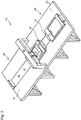
- Fig. 1 shows a device 10 for printing textile surfaces.
- the device 10 has a first set-up station 20 at which a pallet 21 is stored in its set-up position 22.
- the setup station 20 is arranged on a first longitudinal side along a longitudinal beam 50.
- a displacing device 23, which faces a printing device 51, is provided in a front region of the pallet 21.
- the pallet 21 can be moved along a guide rail 40 between the setup position 22 and a printing position below the printing device 51 (see FIG Fig. 2 ).
- the printing device 51 is variably mounted along the longitudinal beam 50 in order to capture the entire width of a pallet that has been delivered and to be able to print a textile located on it over the entire width ( Fig. 2 ).
- several digital print heads (not shown) are provided, which can print a print image on a textile in the print position.
- another pallet 31 is arranged on the guide rail 40 and is located at a second setup station 30 in the second setup position 32.
- a further displacement device 33 is provided on a side facing the printing device 51 and the side member 50, by means of which the pallet 31 can be moved between the second setup position 32 in the second setup station 30 and the common printing position below the side member 50.
- the textile on pallet 31 has an already printed surface.
- the pallets 21, 31 can be fitted with a textile in their respective setup positions 22, 32 and fed to the printing device 51 along a common path 41 on the guide rail 40.
- two pallets 21, 31 are provided along a common axis which runs transversely to the longitudinal beam 50, which in an embodiment which does not fall under the claims can be moved alternately into the common printing position below the longitudinal beam 50.
- Fig. 2 shows the device 10 according to the invention, the further pallet 31 being in the printing position and the pallet 21 in its set-up position 22 in the set-up station 20.
- the printing device 51 By means of the printing device 51, a textile which is located on the further pallet 31 is printed with a print image. The result of such printing is, for example, in Fig. 1 pictured.
- the printing device moves here 51 across the web 41 and the further pallet 31 along the web 41, so that the print heads of the printing device 51 cover the entire printing area on the textile.
- the further pallet 31 moves at least partially under the longitudinal beam 50 to the side of the pallet 21.
- the guide rail 40 is expediently designed continuously for this purpose between the two set-up stations 22, 32.
- the pallet 21 After the textile has been printed on the further pallet 31, in an embodiment which does not fall under the claims, the latter is moved with the printed textile into its set-up position 32 at the set-up station 30, where the printed textile is removed. While the textile is printed on the further pallet 31 in the printing position by the printing device 51, the pallet 21 can already be equipped with a textile in its set-up position 22 at the set-up station 20. As soon as the further pallet 31 in the aforementioned embodiment, which does not fall under the claims, has left the printing position in order to be fed to the further setup station 30, the pallet 21 with the textile to be printed can be moved into the printing position (see for example Fig. 3 , Pallets 21, 31).
- the alternate feeding of the pallets 21, 31 from setup positions 22, 32 to the printing position enables particularly efficient operation of the device with a particularly short idle time of the printing device 51.
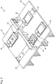
- Fig. 3 shows an embodiment of the device 10 according to the invention, in which two guide rails 40, 42 are arranged parallel to one another and transversely to a longitudinal axis along the longitudinal member 50.
- the setup station 20 thus now has two pallets 21, 24, one of the two pallets being arranged on one of the guide rails 40, 42.
- the pallets 21 and 24 can be moved independently of one another on their respective guide rails 40 and 42 between their setup positions 22, 25 in the setup station 20 and the printing position.
- two further pallets 31, 34 are provided, the further pallet 31 having a printed textile which is moved between the printing position and the second setup station 30 and the further pallet 34 is fed to the printing device 52.
- the pallet 21 is in delivery to the printing position. In an embodiment not falling under the claims, this can already take place while the pallet 31 has not yet reached the second set-up station 30.
- each pallet can be moved linearly from the printing position to the second setup station for removing the pallet on the common guide rail and can be removed from the guide rail.
- a latching system is provided, by means of which each pallet can be reversibly latched on the guide rail.
- An expedient embodiment can consist in that pallet pairs of several parallel guide rails can be printed by means of a single printing device. In the manner described above, any number of pairs of pallets, which are each mounted on a common guide rail, can be provided parallel to one another. This can be an arrangement which is basically a multiple of the embodiment Fig. 1 corresponds. Alternatively, such a device can be designed with only a single printing device by means of which textiles can be printed on all pallets delivered to the printing position.
Landscapes
- Engineering & Computer Science (AREA)
- Textile Engineering (AREA)
- Coloring (AREA)
- Treatment Of Fiber Materials (AREA)
- Ink Jet (AREA)
- Dot-Matrix Printers And Others (AREA)
- Handling Of Cut Paper (AREA)
Description
- Die Erfindung betrifft eine Vorrichtung zum Bedrucken von textilen Oberflächen nach dem Oberbegriff des Anspruchs 1.
- Eine solche Vorrichtung weist mindestens eine Druckeinrichtung, welche entlang einer Längsachse der Vorrichtung in einer Längsrichtung verfahrbar ist, wobei die Druckeinrichtung einen Druckkopf aufweist, mittels welchem mindestens ein Textil mit mindestens einer Druckerfarbe bedruckbar ist, mindestens eine Palette zum Aufnehmen und Halten des zu bedruckenden Textils, eine Rüststation, welche an einer ersten Längsseite zum Zuführen des Textils und Anbringen auf der Palette angeordnet ist, und mindestens eine Verfahreinrichtung auf, mit welcher die mindestens eine Palette quer zur Längsachse zwischen einer ersten seitlichen Rüstposition an der Rüststation und einer Druckposition an der Druckeinrichtung verfahrbar ist.
- Weiterhin betrifft die Erfindung ein Verfahren zum Bedrucken von textilen Oberflächen. Ein solches Verfahren ist im Anspruch 2 definiert.
- Eine gattungsgemäße Vorrichtung und ein entsprechendes Verfahren zum Bedrucken von textilen Oberflächen ist zum Beispiel aus der
EP 1 740 388 A2 bekannt. Bei dieser Vorrichtung und dem entsprechenden Verfahren ist eine Palette mit einem Textil bestückbar, wobei die Palette auf einer Bahn einer Druckeinrichtung zustellbar ist. Die Druckeinrichtung weist mindestens einen digitalen Druckkopf auf und ist entlang einer Längsachse, welche quer zur Verfahrrichtung der Palette ausgebildet ist, in einer Längsrichtung an einer Längsaufhängung verfahrbar gelagert. - Bei einer solchen Vorrichtung wird üblicherweise die Palette entlang der Bahn in einer ersten Position mit einem Textil bestückt und anschließend auf einer Führungsschiene der Druckeinrichtung zum Bedrucken des Textils in einer zweiten Position zugestellt. Während dem Bestücken mit einem Textil oder dem Verfahren der Palette zwischen den Positionen befindet sich die Druckeinrichtung nicht im Druckbetrieb, bis die bestückte Palette der Druckeinrichtung zugestellt ist. Ist die Palette mit dem Textil der Druckeinrichtung zugestellt können durch einen Mitarbeiter keine weiteren Vorbereitungen für einen nächsten Druckzyklus, also dem Bedrucken von weiterem Textil entlang derselben Bahn vorgenommen werden.
- Das Vorsehen mehrerer solcher Vorrichtungen, welche parallel nebeneinander angeordnet sind, mit jeweils einer Palette und einer Führungsschiene, auf welcher die Palette verfahrbar ist, kann lediglich die Effizienz des Mitarbeiters, welcher die Vorrichtung bedient, aber nicht die Effizienz der Druckeinrichtung an sich steigern.
- Die
US 2005/0179708 A1 lehrt eine Druckvorrichtung mit einer Verfahreinrichtung, auf welcher eine Textilhalterung angeordnet ist, welche einer Druckeinrichtung zuführbar ist. Grundsätzlich kann die Druckeinrichtung entlang der Verfahreinrichtung von beiden Seiten mit Textil beschickt werden. - Der vorliegenden Erfindung liegt die Aufgabe zugrunde, eine Vorrichtung zum Bedrucken von textilen Oberflächen sowie ein entsprechendes Verfahren anzugeben, welche es erlauben, die Leerzeit zwischen einzelnen Druckzyklen zu verringern und somit die Effizienz einer solchen Druckvorrichtung merklich zu erhöhen.
- Die Aufgabe wird nach der Erfindung einerseits durch eine Vorrichtung mit den Merkmalen nach Anspruch 1 und andererseits durch ein Verfahren mit den Merkmalen nach Anspruch 2 gelöst. Vorteilhafte Ausgestaltungen sind in der Beschreibung und den Figuren angegeben.
- Ein Grundgedanke der Erfindung besteht darin, an einer Vorrichtung zum Bedrucken textiler Oberflächen mehr als eine Rüststation anzuordnen.
- Die Leerzeit der Druckeinrichtung, also die Zeit in welcher kein Textil durch die Druckeinrichtung bedruckt wird, ist durch die geringere Zeitspanne zwischen dem Abführen eines bedruckten Textils aus der gemeinsamen Druckposition in eine Rüststation und dem Zuführen eines zu bedruckenden Textils indie Druckposition verringert.
- Eine weitere Palette in der zweiten Rüststation kann mit Textil für einen Druck bestückbar sein, während mittels der Druckeinrichtung in der Druckposition ein Textil bedruckbar ist.
- Weiterhin ist es bevorzugt, dass die Paletten entlang der beiden Längsseiten paarweise gegenüberliegend angeordnet sind. Durch eine paarweise Anordnung der mindestens zwei Paletten wäre es in einer Ausführung, die nicht unter die Ansprüche fällt, denkbar, der gemeinsamen Druckposition an der Druckeinrichtung mehr als eine Palette nacheinander von unterschiedlichen Seiten zuzuführen. Somit könnte die gemeinsame Druckposition der Druckeinrichtung besonders effizient genutzt werden. Die paarweise Anordnung der gegenüber liegenden Paletten könnte insbesondere in einer Querrichtung quer zur Längsachse vorgesehen sein.
- Nach Erfindung sind die gegenüberliegenden Paletten entlang einer gemeinsamen Achse zwischen ihren Rüstpositionen in den jeweiligen Rüststationen und der Druckposition verfahrbar. Dies könnte in einer Ausführung, die nicht unter die Ansprüche fällt, den wechselseitigen Betrieb der Vorrichtung ermöglichen, bei welchem die paarweise angeordneten Paletten aus ihren gegenüber liegenden Rüstpositionen der Druckposition auf einer gemeinsamen Führungsschiene zugestellt werden können. Erfindungsgemäß ist es vorgesehen, dass die Paletten in einem linearen Modus durch die Vorrichtung geführt werden können, bei welchem in einer ersten Rüstposition an einer ersten Rüststation eine Palette mit einem Textil bestückbar ist, die Palette entlang der Führungsschiene der Druckeinrichtung zuführbar ist, und nach dem Bedrucken die Palette mit dem bedruckten Textil in die zweite Rüstposition an der zweiten Rüststation zur Entnahme verfahrbar ist. Für einen solchen Betriebsmodus sind die Paletten so ausgebildet, dass sie in besonders einfacher Weise von der Führungsschiene in der zweiten Rüststation entnehmbar sind. Dies ist erfindungsgemäß durch ein Rastsystem ermöglicht, mittels welchem die Paletten auf der Führungsschiene reversibel verrastbar sind.
- Eine zweckmäßige Weiterbildung der Erfindung kann darin bestehen, dass eine Palette der gegenüberliegenden Paletten in der Rüstposition mit einem Textil bestückbar ist, während die andere Palette in der Druckposition gelagert ist.
- Besonders bevorzugt nach der Erfindung ist es, dass in den Rüststationen mehrere nebeneinander angeordnete Paletten vorgesehen sind, wobei die Paletten jeder Rüststation jeweils unabhängig voneinander zwischen ihren seitlichen Rüstpositionen und der Druckposition verfahrbar sind. Das Anordnen mehrerer Paletten an jeder Rüststation kann es ermöglichen in besonders Platz sparender Weise eine Vielzahl der erfindungsgemäßen Druck-Vorrichtungseinheiten vorzusehen, welche jeweils in voranstehend beschriebener Weise ein besonders effizientes Bedrucken von textilen Oberflächen ermöglichen können. Insbesondere unter dem Gesichtspunkt einer wirtschaftlicheren Nutzung von Arbeitskraft kann das Vorsehen von mehreren nebeneinandergelagerten Paletten in den Rüststationen.
- Hierbei können die einzelnen Verfahreinrichtungen der mehreren nebeneinander angeordneten Paletten der Rüststationen parallel zueinander verfahrbar sein. So kann es ermöglicht sein, dass Paletten einer Rüststation durch einen einzelnen Benutzer mit zu bedruckendem Textil bestückbar sind. Weiterhin kann es zweckmäßig sein, dass alle Paletten beider Rüststationen mittels derselben Druckeinrichtung bedruckbar sind. Somit kann eine Druckeinrichtung für das Bedrucken aller zugestellten Textile vorsehbar sein.
- Ein abgewandeltes Verfahren, das nicht unter die Ansprüche fällt, könnte darin bestehen, dass das mindestens eine Textil und das mindestens eine weitere Textil auf ihren jeweiligen Paletten von gegenüberliegenden Längsseiten einer Längsachse aus in die Druckposition verfahren werden. Somit kann zu bedruckendes Textil der Druckposition von gegenüberliegenden Seiten her zugestellt werden. Die jeweiligen Paletten können hierzu an ihren Rüststationen mit Textil bestückt und anschließend der Druckposition zugeführt werden.
- Weiterhin ist es nach einer Weiterbildung der Erfindung bevorzugt, dass die Verfahreinrichtungen der mindestens einen Palette und der mindestens einen weiteren Palette individuell verfahren werden, wobei die Paletten paarweise entlang einer gemeinsamen Achse angeordnet sind, welche sich von der Längsachse unterscheidet. Die Ausrichtung der gemeinsamen Achse ist so ausgestaltet sein, dass die Paletten von den Rüststationen in die Druckposition in einer Querrichtung quer zur Längsrichtung der Vorrichtung der Druckposition zugestellt werden. Besonders bevorzugt ist es nach einer Weiterbildung der Erfindung, dass die zwei Paletten, welche entlang der gemeinsamen Achse verfahren werden, sich im Wechsel in der Druckposition und ihren jeweiligen Rüstpositionen befinden. Ein solches Verfahren kann die besonders effiziente Ausnutzung einer gemeinsamen Druckposition ermöglichen, wodurch die Zeit zwischen einzelnen Druckzyklen, also die Leerzeiten an der Druckposition, deutlich verringert werden kann.
- Es wäre in einer nicht unter die Ansprüche fallenden Ausführung denkbar, dass Paletten derselben Rüststation, unabhängig voneinander zwischen der entsprechenden Rüststation und der Druckposition verfahren werden. Das unabhängige Verfahren von Paletten derselben Rüststation ermöglicht es diese nacheinander mit einem Textil zu bestücken und der Druckeinrichtung zuzuführen. Dadurch kann bereits ein einzelner Benutzer eine Rüststation, welche mehrere Paletten aufweist, mit besonders geringer Leerlaufzeit, in welcher einzelne Paletten unbestückt in der Rüststation verweilen, bedienen.
- Die Erfindung wird nachfolgend anhand der beigefügten, schematischen Zeichnung weiter erläutert. In der Zeichnung zeigt:
- Fig. 1
- eine schematische Darstellung der erfindungsgemäßen Vorrichtung zum Bedrucken von textilen Oberflächen mit einer Palette je Rüststation;
- Fig. 2
- eine schematische Darstellung der erfindungsgemäßen Vorrichtung zum Bedrucken von textilen Oberflächen nach
Fig. 1 , wobei sich eine der Paletten in der gemeinsamen Druckposition befindet und die andere Palette in der Rüstposition gelagert ist; - Fig. 3
- eine schematische Darstellung der erfindungsgemäßen Vorrichtung zum Bedrucken von textilen Oberflächen mit zwei Paletten je Rüststation.
-
Fig. 1 zeigt eine Vorrichtung 10 zum Bedrucken von textilen Oberflächen. Die Vorrichtung 10 weist eine erste Rüststation 20 auf, an welcher eine Palette 21 in ihrer Rüstposition 22 gelagert ist. Die Rüststation 20 ist an einer ersten Längsseite entlang eines Längsträgers 50 angeordnet. An der Palette 21 ist in einem vorderen Bereich eine Verfahreinrichtung 23 vorgesehen, welche einer Druckeinrichtung 51 zugewandt ist. Mittels der Verfahreinrichtung 23 kann die Palette 21 entlang einer Führungsschiene 40 zwischen der Rüstposition 22 und einer Druckposition unterhalb der Druckeinrichtung 51 verfahren werden (sieheFig. 2 ). Die Druckeinrichtung 51 ist entlang des Längsträgers 50 veränderbar gelagert, um die gesamte Breite einer zugestellten Palette zu erfassen und ein darauf befindliches Textil über die gesamte Breite bedrucken zu können (Fig. 2 ). An der Druckeinrichtung 51 nachFig. 1 sind mehrere digitale Druckköpfe (nicht dargestellt) vorgesehen, welche ein Druckbild auf einem Textil in der Druckposition aufdrucken können. - Auf einer gegenüberliegenden zweiten Seite des Längsträgers 50 ist auf der Führungsschiene 40 eine weitere Palette 31 angeordnet, welche sich an einer zweiten Rüststation 30 in der zweiten Rüstposition 32 befindet. An der weiteren Palette 31 ist eine weitere Verfahreinrichtung 33 auf einer der Druckeinrichtung 51 sowie dem Längsträger 50 zugewandten Seite vorgesehen, mittels welcher die Palette 31 zwischen der zweiten Rüstposition 32 in der zweiten Rüststation 30 und der gemeinsamen Druckposition unterhalb des Längsträgers 50 verfahrbar ist. Das Textil auf Palette 31 weist eine bereits bedruckte Oberfläche auf.
- Die Paletten 21, 31 können in ihren jeweiligen Rüstpositionen 22, 32 mit einem Textil bestückt und der Druckeinrichtung 51 entlang einer gemeinsamen Bahn 41 auf der Führungsschiene 40 zugeführt werden. Somit sind entlang einer gemeinsamen Achse, welche quer zu dem Längsträger 50 verläuft zwei Paletten 21, 31 vorgesehen, welche in einer Ausführungsform, die nicht unter die Ansprüche fällt, abwechselnd in die gemeinsame Druckposition unterhalb des Längsträgers 50 verfahrbar sind.
-
Fig. 2 zeigt die erfindungsgemäße Vorrichtung 10, wobei sich die weitere Palette 31 in der Druckposition und die Palette 21 in seiner Rüstposition 22 in der Rüststation 20 befindet. Mittels der Druckeinrichtung 51 wird ein Textil, welches sich auf der weiteren Palette 31 befindet mit einem Druckbild bedruckt. Das Ergebnis eines solchen Drucks ist beispielsweise inFig. 1 abgebildet. Hierbei verfährt die Druckeinrichtung 51 quer zur Bahn 41 und die weitere Palette 31 längs zur Bahn 41, so dass die Druckköpfe der Druckeinrichtung 51 den gesamten Druckbereich auf dem Textil erfassen. Dazu verfährt die weitere Palette 31 zumindest teilweise unter dem Längsträger 50 hindurch auf die Seite der Palette 21. Zweckdienlicherweise ist die Führungsschiene 40 hierfür zwischen den beiden Rüststationen 22, 32 durchgehend ausgebildet. Nach dem Bedrucken des Textils auf der weiteren Palette 31 wird in einer Ausführungsform, die nicht unter die Ansprüche fällt, diese mit dem bedruckten Textil in seine Rüstposition 32 an der Rüststation 30 verfahren, wo das bedruckte Textil entnommen wird. Während das Textil auf der weiteren Palette 31 in der Druckposition durch die Druckeinrichtung 51 bedruckt wird, kann die Palette 21 in seiner Rüstposition 22 an der Rüststation 20 bereits mit einem Textil bestückt werden. Sobald die weitere Palette 31 in der vorgenannten Ausführungsform, die nicht unter die Ansprüche fällt, die Druckposition verlassen hat um der weiteren Rüststation 30 zugeführt zu werden, kann die Palette 21 mit dem zu bedruckenden Textil in die Druckposition verfahren werden (siehe beispielsweiseFig. 3 , Paletten 21, 31). - Durch das wechselseitige Zuführen der Paletten 21, 31 aus Rüstpositionen 22, 32 zu der Druckposition ist ein besonders effizienter Betrieb der Vorrichtung mit besonders geringer Leerzeit der Druckeinrichtung 51 ermöglicht.
-
Fig. 3 zeigt eine Ausführungsform der erfindungsgemäßen Vorrichtung 10, bei welcher zwei Führungsschienen 40, 42 parallel nebeneinander und quer zu einer Längsachse entlang des Längsträgers 50 angeordnet sind. Somit weist nun die Rüststation 20 zwei Paletten 21, 24 auf, wobei jeweils eine der zwei Paletten an einer der Führungsschienen 40, 42 angeordnet ist. Die Paletten 21 und 24 sind unabhängig voneinander auf ihren jeweiligen Führungs-Schienen 40 und 42 zwischen ihren Rüstpositionen 22, 25 in der Rüststation 20 und der Druckposition verfahrbar. Auch in der zweiten Rüststation 30 sind nach der Ausführungsform inFig. 3 zwei weitere Paletten 31, 34 vorgesehen, wobei die weitere Palette 31 ein bedrucktes Textil aufweist, welches zwischen der Druckposition und der zweiten Rüststation 30 verfahren wird und die weitere Palette 34 der Druckeinrichtung 52 zugestellt ist. NachFig. 3 befindet sich die Palette 21 in Zustellung zu der Druckposition. Dies kann in einer nicht unter die Ansprüche fallenden Ausführungsform bereits geschehen, während die Palette 31 die zweite Rüststation 30 noch nicht erreicht hat. Selbiges gilt für die Paletten 24 und 34 - Erfindungsgemäß ist jede Palette aus der Druckposition zu der zweiten Rüststation linear zur Entnahme der Palette auf der gemeinsamen Führungsschiene verfahrbar und von der Führungsschiene entnehmbar. Dazu ist ein Rastsystem vorgesehen, mittels welchem jede Palette auf der Führungsschiene reversibel verrastbar ist.
- Entlang des Längsträgers 50 ist jeweils eine Druckeinrichtung 51, 52 für je ein Paar Paletten, welche auf einer gemeinsamen Schiene 40, 41 gelagert sind, vorgesehen (
Fig. 3 ). Eine zweckmäßige Ausführungsform kann darin bestehen, dass Palettenpaare mehrerer paralleler Führungsschienen mittels einer einzelnen Druckeinrichtung bedruckbar sind. In der voranstehend beschriebenen Weise sind beliebig viele Palettenpaare, welche auf jeweils einer gemeinsamen Führungsschiene gelagert sind parallel nebeneinander vorsehbar. Dabei kann es sich um eine Anordnung handeln, welche dem Grunde nach ein Vielfaches der Ausführungsform nachFig. 1 entspricht. Alternativ kann eine solche Vorrichtung mit nur einer einzelnen Druckeinrichtung ausgebildet sein, mittels welcher Textile auf allen der Druckposition zugestellten Paletten bedruckbar sind.
Claims (2)
- Vorrichtung (10) zum Bedrucken von textilen Oberflächen, mit- einer Druckeinrichtung (51), welche entlang einer Längsachse der Vorrichtung in eine Längsrichtung verfahrbar ist, wobei die Druckeinrichtung (51) einen Druckkopf aufweist, mittels welchem mindestens ein Textil mit mindestens einer Druckerfarbe bedruckbar ist,- zwei Paletten (21, 31) zum Aufnehmen und Halten eines zu bedruckenden Textils,- einer Rüststation (20), welche an einer ersten Längsseite zum Zuführen des Textils und Anbringen auf einer der Paletten (21, 31) angeordnet ist, und- Verfahreinrichtungen (23, 33), mit welchen die Paletten (21, 31) quer zur Längsachse zwischen einer ersten seitlichen Rüstposition (22) an der Rüststation (20) und einer Druckposition an der Druckeinrichtung (51) auf einer gemeinsamen Führungsschiene (40) verfahrbar sind,- wobei eine zweite Rüststation (30) vorgesehen ist, welche an einer zweiten Längsseite angeordnet ist, die der ersten Längsseite gegenüber liegt, dadurch gekennzeichnet,- dass jede Palette (21, 31) aus der Druckposition zu der zweiten Rüststation (30) linear zur Entnahme der Palette (21, 31) auf der gemeinsamen Führungsschiene (40) verfahrbar und von der Führungsschiene (40) entnehmbar ist, und- dass ein Rastsystem vorgesehen ist, mittels welchem jede Palette (21, 31) auf der Führungsschiene (40) reversibel verrastbar ist.
- Verfahren zum Bedrucken von textilen Oberflächen, mit einer Vorrichtung (10) nach Anspruch 1, bei welchem für jede Palette (21, 31)- ein Textil auf eine Palette (21, 31) aufgenommen und gehaltert wird, wobei sich die Palette (21, 31) an der Rüststation (20) in einer ersten seitlichen Rüstposition (22) an einer ersten Längsseite befindet,- das Textil mittels einer Verfahreinrichtung (23, 33) zwischen der ersten seitlichen Rüstposition (22) an der ersten Längsseite der Rüststation (20) und einer Druckposition an einer Druckeinrichtung (51) verfahren wird, und- das Textil in der Druckposition durch die Druckeinrichtung (51) mittels mindestens eines Druckkopfs, welcher längs einer Längsachse verfahren wird, bedruckt wird,- das bedruckte Textil mittels der Verfahreinrichtung (23) der jeweiligen Palette (21, 31) von der Druckposition linear in eine zweite seitliche Rüstposition (32) an der zweiten Rüststation (30) zur Entnahme verfahren wird, und - die Paletten (21, 31) nach dem Bedrucken in der Druckposition in der zweiten Rüststation (30) mit dem Textil von der Führungsschiene (40) entnommen werden.
Priority Applications (12)
| Application Number | Priority Date | Filing Date | Title |
|---|---|---|---|
| EP15177435.3A EP3121015B1 (de) | 2015-07-20 | 2015-07-20 | Vorrichtung und verfahren zum bedrucken von textilen oberflächen |
| PT151774353T PT3121015T (pt) | 2015-07-20 | 2015-07-20 | Dispositivo e processo para impressão de superfícies têxteis |
| ES15177435T ES2869382T3 (es) | 2015-07-20 | 2015-07-20 | Dispositivo y procedimiento para la impresión de superficies textiles |
| US15/746,301 US10232637B2 (en) | 2015-07-20 | 2016-07-20 | Device and method for printing textile surfaces |
| CN201680042701.9A CN107921786B (zh) | 2015-07-20 | 2016-07-20 | 用于印刷织物表面的装置和方法 |
| EA201890054A EA034021B1 (ru) | 2015-07-20 | 2016-07-20 | Устройство и способ печатания текстильных поверхностей |
| CA2991946A CA2991946C (en) | 2015-07-20 | 2016-07-20 | Device and method for printing textile surfaces |
| PCT/EP2016/067272 WO2017013166A1 (de) | 2015-07-20 | 2016-07-20 | Vorrichtung und verfahren zum bedrucken von textilen oberflächen |
| BR112018000775-7A BR112018000775B1 (pt) | 2015-07-20 | 2016-07-20 | Dispositivo e método para imprimir superfícies têxteis |
| KR1020187004924A KR102206723B1 (ko) | 2015-07-20 | 2016-07-20 | 직물 표면 인쇄 장치 및 방법 |
| JP2018503522A JP6936785B2 (ja) | 2015-07-20 | 2016-07-20 | 布地表面をプリントする装置および方法 |
| HK17105941.0A HK1232189A1 (zh) | 2015-07-20 | 2017-06-15 | 用於印刷織物表面的設備和方法 |
Applications Claiming Priority (1)
| Application Number | Priority Date | Filing Date | Title |
|---|---|---|---|
| EP15177435.3A EP3121015B1 (de) | 2015-07-20 | 2015-07-20 | Vorrichtung und verfahren zum bedrucken von textilen oberflächen |
Publications (2)
| Publication Number | Publication Date |
|---|---|
| EP3121015A1 EP3121015A1 (de) | 2017-01-25 |
| EP3121015B1 true EP3121015B1 (de) | 2021-02-24 |
Family
ID=53673844
Family Applications (1)
| Application Number | Title | Priority Date | Filing Date |
|---|---|---|---|
| EP15177435.3A Active EP3121015B1 (de) | 2015-07-20 | 2015-07-20 | Vorrichtung und verfahren zum bedrucken von textilen oberflächen |
Country Status (12)
| Country | Link |
|---|---|
| US (1) | US10232637B2 (de) |
| EP (1) | EP3121015B1 (de) |
| JP (1) | JP6936785B2 (de) |
| KR (1) | KR102206723B1 (de) |
| CN (1) | CN107921786B (de) |
| BR (1) | BR112018000775B1 (de) |
| CA (1) | CA2991946C (de) |
| EA (1) | EA034021B1 (de) |
| ES (1) | ES2869382T3 (de) |
| HK (1) | HK1232189A1 (de) |
| PT (1) | PT3121015T (de) |
| WO (1) | WO2017013166A1 (de) |
Families Citing this family (9)
| Publication number | Priority date | Publication date | Assignee | Title |
|---|---|---|---|---|
| PL3781407T3 (pl) | 2018-08-01 | 2022-06-20 | Angelo Schiestl | System drukujący i sposób zadrukowywania produktów zadrukowywalnych |
| EP3738778B1 (de) * | 2019-05-14 | 2023-06-28 | Angelo Schiestl | Druckmaschine und verfahren zum bedrucken von textilien |
| JP7175296B2 (ja) | 2020-07-15 | 2022-11-18 | ローランドディー.ジー.株式会社 | 印刷用治具および印刷装置 |
| DE212021000011U1 (de) * | 2021-03-02 | 2021-06-02 | Suzhou Kangfu Intelligent Technology Co., Ltd. | Eine Vorrichtung zur Herstellung flexibler Verbundgewebe |
| CN114670557B (zh) * | 2021-03-31 | 2023-07-21 | 厦门汉印电子技术有限公司 | 一种成衣打印机及成衣打印工艺 |
| CN113858824B (zh) * | 2021-10-27 | 2023-06-23 | 浙江隆生数码纺织科技有限公司 | 一种水性热熔胶墨水数码印花设备 |
| EP4289631A1 (de) | 2022-06-09 | 2023-12-13 | Angelo Schiestl | Druckanlage und verfahren zum bedrucken von druckgut |
| KR102690160B1 (ko) * | 2022-06-14 | 2024-07-30 | 김대갑 | 섬유원단용 발염 스피드 프린터 |
| WO2023249615A1 (en) * | 2022-06-21 | 2023-12-28 | Hewlett-Packard Development Company, L.P. | Printing with a plurality of trays |
Family Cites Families (10)
| Publication number | Priority date | Publication date | Assignee | Title |
|---|---|---|---|---|
| US6059391A (en) * | 1997-08-19 | 2000-05-09 | Fulkerson; Timothy Jerome | Apparatus and method for ink jet printing on large or irregular fabrics |
| KR200189488Y1 (ko) * | 1999-12-29 | 2000-07-15 | 박상업 | 디지털 날염용 잉크젯 프린터 |
| US20070103529A1 (en) * | 2003-06-16 | 2007-05-10 | Kornit Digital Ltd. | Process and system for printing images on absorptive surfaces |
| US7607745B2 (en) * | 2004-02-12 | 2009-10-27 | Kornit Digital Ltd. | Digital printing machine |
| ATE552981T1 (de) | 2004-02-12 | 2012-04-15 | Kornit Digital Technologies Ltd | Digitale druckvorrichtung |
| JP5062427B2 (ja) * | 2008-03-24 | 2012-10-31 | ブラザー工業株式会社 | 印刷装置 |
| CN201287505Y (zh) * | 2008-09-24 | 2009-08-12 | 徐中九 | 一种彩色喷印机 |
| US8177442B2 (en) * | 2009-05-21 | 2012-05-15 | Hbi Branded Apparel Enterprises, Llc | Digital printing machine and platen assembly for printing on multiple garment portions |
| US8540358B2 (en) * | 2009-08-10 | 2013-09-24 | Kornit Digital Ltd. | Inkjet compositions and processes for stretchable substrates |
| JP5982988B2 (ja) * | 2012-04-24 | 2016-08-31 | セイコーエプソン株式会社 | セットトレイ、インクジェット捺染装置、セットトレイの保管方法及び印捺物の製造方法 |
-
2015
- 2015-07-20 PT PT151774353T patent/PT3121015T/pt unknown
- 2015-07-20 EP EP15177435.3A patent/EP3121015B1/de active Active
- 2015-07-20 ES ES15177435T patent/ES2869382T3/es active Active
-
2016
- 2016-07-20 KR KR1020187004924A patent/KR102206723B1/ko active IP Right Grant
- 2016-07-20 BR BR112018000775-7A patent/BR112018000775B1/pt active IP Right Grant
- 2016-07-20 US US15/746,301 patent/US10232637B2/en active Active
- 2016-07-20 CA CA2991946A patent/CA2991946C/en active Active
- 2016-07-20 EA EA201890054A patent/EA034021B1/ru not_active IP Right Cessation
- 2016-07-20 CN CN201680042701.9A patent/CN107921786B/zh active Active
- 2016-07-20 WO PCT/EP2016/067272 patent/WO2017013166A1/de active Application Filing
- 2016-07-20 JP JP2018503522A patent/JP6936785B2/ja active Active
-
2017
- 2017-06-15 HK HK17105941.0A patent/HK1232189A1/zh unknown
Non-Patent Citations (1)
| Title |
|---|
| None * |
Also Published As
| Publication number | Publication date |
|---|---|
| JP2018529546A (ja) | 2018-10-11 |
| JP6936785B2 (ja) | 2021-09-22 |
| KR102206723B1 (ko) | 2021-01-25 |
| WO2017013166A1 (de) | 2017-01-26 |
| US10232637B2 (en) | 2019-03-19 |
| CA2991946A1 (en) | 2017-01-26 |
| ES2869382T3 (es) | 2021-10-25 |
| EA201890054A1 (ru) | 2018-07-31 |
| US20180215171A1 (en) | 2018-08-02 |
| CA2991946C (en) | 2021-07-13 |
| BR112018000775B1 (pt) | 2023-11-07 |
| CN107921786B (zh) | 2019-09-10 |
| EP3121015A1 (de) | 2017-01-25 |
| HK1232189A1 (zh) | 2018-01-05 |
| PT3121015T (pt) | 2021-05-18 |
| BR112018000775A2 (pt) | 2019-05-07 |
| KR20180035231A (ko) | 2018-04-05 |
| EA034021B1 (ru) | 2019-12-19 |
| CN107921786A (zh) | 2018-04-17 |
Similar Documents
| Publication | Publication Date | Title |
|---|---|---|
| EP3121015B1 (de) | Vorrichtung und verfahren zum bedrucken von textilen oberflächen | |
| DE3234216C2 (de) | ||
| AT514929B1 (de) | Werkzeugrüstsystem für Biegepresse | |
| AT518520B1 (de) | Werkzeug-Speichersystem, Fertigungsanlage sowie Verfahren zum Manipulieren mit einem derartigen Werkzeug-Speichersystem | |
| WO1986003153A1 (fr) | Systeme de fabrication flexible pour le traitement et la production d'ensembles a plusieurs parties, en particulier d'ensembles de carrosseries brutes. | |
| DE102010056123B3 (de) | Drucktischanordnung, Verfahren zum Betreiben einer Drucktischanordnung | |
| EP1979128B1 (de) | Vorrichtung zur handhabung von teilen jedweder art, insbesondere zum linearen be- und entladen von maschinen | |
| DE102007059303A1 (de) | Verarbeitungsanlage | |
| EP1990160A2 (de) | Durchlaufbohrmaschine | |
| DE2731762C2 (de) | Verfahren und Vorrichtung zum Herstellen von Bürsten | |
| DE19925217A1 (de) | Verfahren zum Bestücken von Substraten mit Bauelementen | |
| EP2484483A1 (de) | Zuführ- und Ladeeinheit | |
| EP1365886B1 (de) | Werkstückspanntisch | |
| EP3028806A1 (de) | Bearbeitungsvorrichtung | |
| DE4224522C1 (de) | Verfahren und Pressenanlage zur Herstellung plattenförmiger, beidseitig mit Furnier versehener Werkstücke | |
| WO2017109036A1 (de) | Vorrichtung und verfahren zum bedrucken von druckgütern | |
| DE102007028786B4 (de) | Vorrichtung zum Fördern von Holzplatten oder dergleichen | |
| EP1186219B1 (de) | Verfahren zum bestücken von substraten mit bauelementen | |
| WO1997015513A1 (de) | Vorrichtung zum ausziehen von rollpaletten in der kompakt-lagertechnik, sowie rollpalette hierfür | |
| WO2018099515A2 (de) | VERFAHREN ZUM BONDEN GROßER MODULE UND BONDANORDNUNG | |
| DE102008024558A1 (de) | Positioniersystem für Werkzeuge | |
| EP2949439B1 (de) | Bearbeitungsvorrichtung und bearbeitungsverfahren | |
| DE10047385C2 (de) | Verfahren und Vorrichtung zur Bearbeitung von fortlaufend bewegten Werkstücken | |
| AT402052B (de) | Einrichtung zum ausrichten und stapeln von formatzuschnitten | |
| DE102018102417A1 (de) | Vorrichtung zum Transportieren und Ausrichten von einem oder mehreren flächigen Bauteilen |
Legal Events
| Date | Code | Title | Description |
|---|---|---|---|
| PUAI | Public reference made under article 153(3) epc to a published international application that has entered the european phase |
Free format text: ORIGINAL CODE: 0009012 |
|
| STAA | Information on the status of an ep patent application or granted ep patent |
Free format text: STATUS: THE APPLICATION HAS BEEN PUBLISHED |
|
| AK | Designated contracting states |
Kind code of ref document: A1 Designated state(s): AL AT BE BG CH CY CZ DE DK EE ES FI FR GB GR HR HU IE IS IT LI LT LU LV MC MK MT NL NO PL PT RO RS SE SI SK SM TR |
|
| AX | Request for extension of the european patent |
Extension state: BA ME |
|
| STAA | Information on the status of an ep patent application or granted ep patent |
Free format text: STATUS: REQUEST FOR EXAMINATION WAS MADE |
|
| 17P | Request for examination filed |
Effective date: 20170620 |
|
| RBV | Designated contracting states (corrected) |
Designated state(s): AL AT BE BG CH CY CZ DE DK EE ES FI FR GB GR HR HU IE IS IT LI LT LU LV MC MK MT NL NO PL PT RO RS SE SI SK SM TR |
|
| RAP1 | Party data changed (applicant data changed or rights of an application transferred) |
Owner name: SCHIESTL, ANGELO |
|
| RIN1 | Information on inventor provided before grant (corrected) |
Inventor name: SCHIESTL, ANGELO |
|
| REG | Reference to a national code |
Ref country code: HK Ref legal event code: DE Ref document number: 1232189 Country of ref document: HK |
|
| STAA | Information on the status of an ep patent application or granted ep patent |
Free format text: STATUS: EXAMINATION IS IN PROGRESS |
|
| 17Q | First examination report despatched |
Effective date: 20191111 |
|
| GRAP | Despatch of communication of intention to grant a patent |
Free format text: ORIGINAL CODE: EPIDOSNIGR1 |
|
| STAA | Information on the status of an ep patent application or granted ep patent |
Free format text: STATUS: GRANT OF PATENT IS INTENDED |
|
| INTG | Intention to grant announced |
Effective date: 20201126 |
|
| GRAS | Grant fee paid |
Free format text: ORIGINAL CODE: EPIDOSNIGR3 |
|
| GRAA | (expected) grant |
Free format text: ORIGINAL CODE: 0009210 |
|
| STAA | Information on the status of an ep patent application or granted ep patent |
Free format text: STATUS: THE PATENT HAS BEEN GRANTED |
|
| AK | Designated contracting states |
Kind code of ref document: B1 Designated state(s): AL AT BE BG CH CY CZ DE DK EE ES FI FR GB GR HR HU IE IS IT LI LT LU LV MC MK MT NL NO PL PT RO RS SE SI SK SM TR |
|
| REG | Reference to a national code |
Ref country code: GB Ref legal event code: FG4D Free format text: NOT ENGLISH |
|
| REG | Reference to a national code |
Ref country code: CH Ref legal event code: EP |
|
| REG | Reference to a national code |
Ref country code: DE Ref legal event code: R096 Ref document number: 502015014281 Country of ref document: DE |
|
| REG | Reference to a national code |
Ref country code: AT Ref legal event code: REF Ref document number: 1363958 Country of ref document: AT Kind code of ref document: T Effective date: 20210315 |
|
| REG | Reference to a national code |
Ref country code: IE Ref legal event code: FG4D Free format text: LANGUAGE OF EP DOCUMENT: GERMAN |
|
| REG | Reference to a national code |
Ref country code: NL Ref legal event code: FP |
|
| REG | Reference to a national code |
Ref country code: CH Ref legal event code: NV Representative=s name: BOGENSBERGER PATENT- AND MARKENBUERO DR. BURKHA, LI |
|
| REG | Reference to a national code |
Ref country code: PT Ref legal event code: SC4A Ref document number: 3121015 Country of ref document: PT Date of ref document: 20210518 Kind code of ref document: T Free format text: AVAILABILITY OF NATIONAL TRANSLATION Effective date: 20210512 |
|
| REG | Reference to a national code |
Ref country code: GR Ref legal event code: EP Ref document number: 20210401212 Country of ref document: GR Effective date: 20210614 |
|
| REG | Reference to a national code |
Ref country code: LT Ref legal event code: MG9D |
|
| PG25 | Lapsed in a contracting state [announced via postgrant information from national office to epo] |
Ref country code: LT Free format text: LAPSE BECAUSE OF FAILURE TO SUBMIT A TRANSLATION OF THE DESCRIPTION OR TO PAY THE FEE WITHIN THE PRESCRIBED TIME-LIMIT Effective date: 20210224 Ref country code: HR Free format text: LAPSE BECAUSE OF FAILURE TO SUBMIT A TRANSLATION OF THE DESCRIPTION OR TO PAY THE FEE WITHIN THE PRESCRIBED TIME-LIMIT Effective date: 20210224 Ref country code: FI Free format text: LAPSE BECAUSE OF FAILURE TO SUBMIT A TRANSLATION OF THE DESCRIPTION OR TO PAY THE FEE WITHIN THE PRESCRIBED TIME-LIMIT Effective date: 20210224 Ref country code: NO Free format text: LAPSE BECAUSE OF FAILURE TO SUBMIT A TRANSLATION OF THE DESCRIPTION OR TO PAY THE FEE WITHIN THE PRESCRIBED TIME-LIMIT Effective date: 20210524 Ref country code: BG Free format text: LAPSE BECAUSE OF FAILURE TO SUBMIT A TRANSLATION OF THE DESCRIPTION OR TO PAY THE FEE WITHIN THE PRESCRIBED TIME-LIMIT Effective date: 20210524 |
|
| PG25 | Lapsed in a contracting state [announced via postgrant information from national office to epo] |
Ref country code: LV Free format text: LAPSE BECAUSE OF FAILURE TO SUBMIT A TRANSLATION OF THE DESCRIPTION OR TO PAY THE FEE WITHIN THE PRESCRIBED TIME-LIMIT Effective date: 20210224 Ref country code: PL Free format text: LAPSE BECAUSE OF FAILURE TO SUBMIT A TRANSLATION OF THE DESCRIPTION OR TO PAY THE FEE WITHIN THE PRESCRIBED TIME-LIMIT Effective date: 20210224 Ref country code: RS Free format text: LAPSE BECAUSE OF FAILURE TO SUBMIT A TRANSLATION OF THE DESCRIPTION OR TO PAY THE FEE WITHIN THE PRESCRIBED TIME-LIMIT Effective date: 20210224 Ref country code: SE Free format text: LAPSE BECAUSE OF FAILURE TO SUBMIT A TRANSLATION OF THE DESCRIPTION OR TO PAY THE FEE WITHIN THE PRESCRIBED TIME-LIMIT Effective date: 20210224 |
|
| PG25 | Lapsed in a contracting state [announced via postgrant information from national office to epo] |
Ref country code: IS Free format text: LAPSE BECAUSE OF FAILURE TO SUBMIT A TRANSLATION OF THE DESCRIPTION OR TO PAY THE FEE WITHIN THE PRESCRIBED TIME-LIMIT Effective date: 20210624 |
|
| REG | Reference to a national code |
Ref country code: ES Ref legal event code: FG2A Ref document number: 2869382 Country of ref document: ES Kind code of ref document: T3 Effective date: 20211025 |
|
| PG25 | Lapsed in a contracting state [announced via postgrant information from national office to epo] |
Ref country code: CZ Free format text: LAPSE BECAUSE OF FAILURE TO SUBMIT A TRANSLATION OF THE DESCRIPTION OR TO PAY THE FEE WITHIN THE PRESCRIBED TIME-LIMIT Effective date: 20210224 Ref country code: EE Free format text: LAPSE BECAUSE OF FAILURE TO SUBMIT A TRANSLATION OF THE DESCRIPTION OR TO PAY THE FEE WITHIN THE PRESCRIBED TIME-LIMIT Effective date: 20210224 Ref country code: SM Free format text: LAPSE BECAUSE OF FAILURE TO SUBMIT A TRANSLATION OF THE DESCRIPTION OR TO PAY THE FEE WITHIN THE PRESCRIBED TIME-LIMIT Effective date: 20210224 |
|
| REG | Reference to a national code |
Ref country code: DE Ref legal event code: R097 Ref document number: 502015014281 Country of ref document: DE |
|
| PG25 | Lapsed in a contracting state [announced via postgrant information from national office to epo] |
Ref country code: DK Free format text: LAPSE BECAUSE OF FAILURE TO SUBMIT A TRANSLATION OF THE DESCRIPTION OR TO PAY THE FEE WITHIN THE PRESCRIBED TIME-LIMIT Effective date: 20210224 Ref country code: RO Free format text: LAPSE BECAUSE OF FAILURE TO SUBMIT A TRANSLATION OF THE DESCRIPTION OR TO PAY THE FEE WITHIN THE PRESCRIBED TIME-LIMIT Effective date: 20210224 Ref country code: SK Free format text: LAPSE BECAUSE OF FAILURE TO SUBMIT A TRANSLATION OF THE DESCRIPTION OR TO PAY THE FEE WITHIN THE PRESCRIBED TIME-LIMIT Effective date: 20210224 |
|
| PLBE | No opposition filed within time limit |
Free format text: ORIGINAL CODE: 0009261 |
|
| STAA | Information on the status of an ep patent application or granted ep patent |
Free format text: STATUS: NO OPPOSITION FILED WITHIN TIME LIMIT |
|
| PG25 | Lapsed in a contracting state [announced via postgrant information from national office to epo] |
Ref country code: AL Free format text: LAPSE BECAUSE OF FAILURE TO SUBMIT A TRANSLATION OF THE DESCRIPTION OR TO PAY THE FEE WITHIN THE PRESCRIBED TIME-LIMIT Effective date: 20210224 |
|
| 26N | No opposition filed |
Effective date: 20211125 |
|
| PG25 | Lapsed in a contracting state [announced via postgrant information from national office to epo] |
Ref country code: SI Free format text: LAPSE BECAUSE OF FAILURE TO SUBMIT A TRANSLATION OF THE DESCRIPTION OR TO PAY THE FEE WITHIN THE PRESCRIBED TIME-LIMIT Effective date: 20210224 |
|
| PG25 | Lapsed in a contracting state [announced via postgrant information from national office to epo] |
Ref country code: MC Free format text: LAPSE BECAUSE OF FAILURE TO SUBMIT A TRANSLATION OF THE DESCRIPTION OR TO PAY THE FEE WITHIN THE PRESCRIBED TIME-LIMIT Effective date: 20210224 |
|
| REG | Reference to a national code |
Ref country code: BE Ref legal event code: MM Effective date: 20210731 |
|
| PG25 | Lapsed in a contracting state [announced via postgrant information from national office to epo] |
Ref country code: IS Free format text: LAPSE BECAUSE OF FAILURE TO SUBMIT A TRANSLATION OF THE DESCRIPTION OR TO PAY THE FEE WITHIN THE PRESCRIBED TIME-LIMIT Effective date: 20210624 Ref country code: LU Free format text: LAPSE BECAUSE OF NON-PAYMENT OF DUE FEES Effective date: 20210720 |
|
| PG25 | Lapsed in a contracting state [announced via postgrant information from national office to epo] |
Ref country code: IE Free format text: LAPSE BECAUSE OF NON-PAYMENT OF DUE FEES Effective date: 20210720 Ref country code: BE Free format text: LAPSE BECAUSE OF NON-PAYMENT OF DUE FEES Effective date: 20210731 |
|
| PG25 | Lapsed in a contracting state [announced via postgrant information from national office to epo] |
Ref country code: HU Free format text: LAPSE BECAUSE OF FAILURE TO SUBMIT A TRANSLATION OF THE DESCRIPTION OR TO PAY THE FEE WITHIN THE PRESCRIBED TIME-LIMIT; INVALID AB INITIO Effective date: 20150720 |
|
| P01 | Opt-out of the competence of the unified patent court (upc) registered |
Effective date: 20230508 |
|
| PG25 | Lapsed in a contracting state [announced via postgrant information from national office to epo] |
Ref country code: CY Free format text: LAPSE BECAUSE OF FAILURE TO SUBMIT A TRANSLATION OF THE DESCRIPTION OR TO PAY THE FEE WITHIN THE PRESCRIBED TIME-LIMIT Effective date: 20210224 |
|
| PGFP | Annual fee paid to national office [announced via postgrant information from national office to epo] |
Ref country code: TR Payment date: 20230719 Year of fee payment: 9 Ref country code: IT Payment date: 20230731 Year of fee payment: 9 Ref country code: GB Payment date: 20230724 Year of fee payment: 9 Ref country code: ES Payment date: 20230821 Year of fee payment: 9 Ref country code: CH Payment date: 20230801 Year of fee payment: 9 Ref country code: AT Payment date: 20230718 Year of fee payment: 9 |
|
| PGFP | Annual fee paid to national office [announced via postgrant information from national office to epo] |
Ref country code: GR Payment date: 20230718 Year of fee payment: 9 Ref country code: FR Payment date: 20230724 Year of fee payment: 9 Ref country code: DE Payment date: 20230726 Year of fee payment: 9 |
|
| PG25 | Lapsed in a contracting state [announced via postgrant information from national office to epo] |
Ref country code: MK Free format text: LAPSE BECAUSE OF FAILURE TO SUBMIT A TRANSLATION OF THE DESCRIPTION OR TO PAY THE FEE WITHIN THE PRESCRIBED TIME-LIMIT Effective date: 20210224 |
|
| PGFP | Annual fee paid to national office [announced via postgrant information from national office to epo] |
Ref country code: PT Payment date: 20240625 Year of fee payment: 10 |
|
| PGFP | Annual fee paid to national office [announced via postgrant information from national office to epo] |
Ref country code: NL Payment date: 20240722 Year of fee payment: 10 |