EP3120732A1 - Mechanik für einen bürostuhl - Google Patents
Mechanik für einen bürostuhl Download PDFInfo
- Publication number
- EP3120732A1 EP3120732A1 EP16001495.7A EP16001495A EP3120732A1 EP 3120732 A1 EP3120732 A1 EP 3120732A1 EP 16001495 A EP16001495 A EP 16001495A EP 3120732 A1 EP3120732 A1 EP 3120732A1
- Authority
- EP
- European Patent Office
- Prior art keywords
- support
- seat
- backrest
- seat support
- base support
- Prior art date
- Legal status (The legal status is an assumption and is not a legal conclusion. Google has not performed a legal analysis and makes no representation as to the accuracy of the status listed.)
- Granted
Links
- 230000008878 coupling Effects 0.000 claims description 23
- 238000010168 coupling process Methods 0.000 claims description 23
- 238000005859 coupling reaction Methods 0.000 claims description 23
- 238000006073 displacement reaction Methods 0.000 claims description 4
- 230000037396 body weight Effects 0.000 description 2
- 238000010276 construction Methods 0.000 description 2
- 230000000875 corresponding effect Effects 0.000 description 2
- 238000004519 manufacturing process Methods 0.000 description 2
- 230000007935 neutral effect Effects 0.000 description 2
- 230000015572 biosynthetic process Effects 0.000 description 1
- 230000006835 compression Effects 0.000 description 1
- 238000007906 compression Methods 0.000 description 1
- 230000002596 correlated effect Effects 0.000 description 1
- 230000001419 dependent effect Effects 0.000 description 1
- 230000000694 effects Effects 0.000 description 1
- 230000001360 synchronised effect Effects 0.000 description 1
Images


Classifications
-
- A—HUMAN NECESSITIES
- A47—FURNITURE; DOMESTIC ARTICLES OR APPLIANCES; COFFEE MILLS; SPICE MILLS; SUCTION CLEANERS IN GENERAL
- A47C—CHAIRS; SOFAS; BEDS
- A47C1/00—Chairs adapted for special purposes
- A47C1/02—Reclining or easy chairs
- A47C1/031—Reclining or easy chairs having coupled concurrently adjustable supporting parts
- A47C1/032—Reclining or easy chairs having coupled concurrently adjustable supporting parts the parts being movably-coupled seat and back-rest
- A47C1/03261—Reclining or easy chairs having coupled concurrently adjustable supporting parts the parts being movably-coupled seat and back-rest characterised by elastic means
- A47C1/03266—Reclining or easy chairs having coupled concurrently adjustable supporting parts the parts being movably-coupled seat and back-rest characterised by elastic means with adjustable elasticity
-
- A—HUMAN NECESSITIES
- A47—FURNITURE; DOMESTIC ARTICLES OR APPLIANCES; COFFEE MILLS; SPICE MILLS; SUCTION CLEANERS IN GENERAL
- A47C—CHAIRS; SOFAS; BEDS
- A47C1/00—Chairs adapted for special purposes
- A47C1/02—Reclining or easy chairs
- A47C1/031—Reclining or easy chairs having coupled concurrently adjustable supporting parts
- A47C1/032—Reclining or easy chairs having coupled concurrently adjustable supporting parts the parts being movably-coupled seat and back-rest
- A47C1/03255—Reclining or easy chairs having coupled concurrently adjustable supporting parts the parts being movably-coupled seat and back-rest with a central column, e.g. rocking office chairs
-
- A—HUMAN NECESSITIES
- A47—FURNITURE; DOMESTIC ARTICLES OR APPLIANCES; COFFEE MILLS; SPICE MILLS; SUCTION CLEANERS IN GENERAL
- A47C—CHAIRS; SOFAS; BEDS
- A47C1/00—Chairs adapted for special purposes
- A47C1/02—Reclining or easy chairs
- A47C1/031—Reclining or easy chairs having coupled concurrently adjustable supporting parts
- A47C1/032—Reclining or easy chairs having coupled concurrently adjustable supporting parts the parts being movably-coupled seat and back-rest
- A47C1/03261—Reclining or easy chairs having coupled concurrently adjustable supporting parts the parts being movably-coupled seat and back-rest characterised by elastic means
- A47C1/03272—Reclining or easy chairs having coupled concurrently adjustable supporting parts the parts being movably-coupled seat and back-rest characterised by elastic means with coil springs
-
- A—HUMAN NECESSITIES
- A47—FURNITURE; DOMESTIC ARTICLES OR APPLIANCES; COFFEE MILLS; SPICE MILLS; SUCTION CLEANERS IN GENERAL
- A47C—CHAIRS; SOFAS; BEDS
- A47C1/00—Chairs adapted for special purposes
- A47C1/02—Reclining or easy chairs
- A47C1/031—Reclining or easy chairs having coupled concurrently adjustable supporting parts
- A47C1/032—Reclining or easy chairs having coupled concurrently adjustable supporting parts the parts being movably-coupled seat and back-rest
- A47C1/03294—Reclining or easy chairs having coupled concurrently adjustable supporting parts the parts being movably-coupled seat and back-rest slidingly movable in the base frame, e.g. by rollers
-
- A—HUMAN NECESSITIES
- A47—FURNITURE; DOMESTIC ARTICLES OR APPLIANCES; COFFEE MILLS; SPICE MILLS; SUCTION CLEANERS IN GENERAL
- A47C—CHAIRS; SOFAS; BEDS
- A47C7/00—Parts, details, or accessories of chairs or stools
- A47C7/002—Chair or stool bases
- A47C7/004—Chair or stool bases for chairs or stools with central column, e.g. office chairs
Definitions
- the invention relates to a mechanism for an office chair with a base support placeable on a chair column, with a arranged on the base support, relative to the base support movable seat support and coupled to the seat support backrest, wherein pivoting the backrest movement of the seat support relative to the Causes base carrier.
- a kinematics is provided which brings a certain relative movement of the seat and backrest to each other, so that there is a correlated seat-backrest movement.
- This seat and backrest are pivoted together backwards down.
- the seat in the loaded state should be able to assume a position deviating from the horizontal position, slightly inclined forward.
- the inclination resistance of the seat support is indeed adjustable.
- this is often solved structurally complicated. Additional components increase the production and assembly costs and require a corresponding space.
- An object of the present invention is to provide an alternative solution for adjusting the inclination resistance of the seat support of an office chair. This object is achieved by a mechanism according to claim 1.
- Advantageous embodiments of the invention are specified in the subclaims.
- a basic idea of the invention is to provide a seat carrier which can be tilted forward out of the horizontal against the spring force of a spring arrangement acting on the seat carrier, wherein the same spring arrangement also acts on the backrest carrier.
- the spring arrangement used for adjusting the pivoting resistance of the backrest support is used for adjusting the inclination resistance of the seat support.
- the seat support is, preferably using a suitable movable coupling element between the base support and the seat support, lowered in a possession of the chair in its front region against the spring force of the spring assembly and accordingly when relieving the seat by means of the spring force off automatically to its original position or Erected.
- a suitable movable coupling element between the base support and the seat support, lowered in a possession of the chair in its front region against the spring force of the spring assembly and accordingly when relieving the seat by means of the spring force off automatically to its original position or Erected.
- a presetting of the spring force of the spring arrangement with respect to the weight of the user has a direct effect on the side-tilt functionality.
- the spring action for the seat tilt also harder, so that automatically results in a stronger spring action for lowering into the seat tilt position.
- the more the swinging resistance of the backrest is adjusted the stronger the inclination resistance of the seat will be.
- the rocking or rocking of the seat in the seat tilt position for all user weights is equally enabled and felt by all users, regardless of their weight, equally if the mechanics, in particular the spring arrangement of the mechanism, is adjusted to the user suitable.
- the basic idea of the invention is independent of the specific movement carried out by the seat support relative to the base support. In general, however, in the movement of the seat support is a movement in the seat longitudinal direction, which is superimposed by a tilting, pivoting and / or tilting movement of the seat support.
- the mechanism 1 for an office chair comprises a means of in Fig. 1 indicated Konusfact 2 on the upper end of a chair column (not shown) placeable, preferably fixed base support. 3
- On the seat support 4 is usually provided with a padded seat seat (not shown) of the office chair mounted.
- the mechanism 1 further comprises an associated both with the base support 3, and with the seat support 4, relative to the base support 3 movable backrest support 5, the pivoting causes movement of the seat support 4 relative to the base support 3.
- the cheeks 6 of the backrest support 5 forked in plan view are arranged on both sides of the base support 3.
- the mechanism 1 is mirror-symmetrical in terms of the central longitudinal plane, as far as the actual kinematics is concerned. In that regard, in the following description is always on both sides pairwise existing construction elements of the mechanism 1 go out.
- front or “front” means that a component in the seat longitudinal direction 7 is arranged at the front or refers to a component extending in the direction of the front seat edge 8 or pointing in this direction
- rear or “rear” means in that a component is arranged at the rear in the seat longitudinal direction 7 or refers to a component extending in the direction of the backrest or the backrest support 5 or the rear seat edge 9 or pointing in this direction.
- the statements “above” and “below” refer to the intended use state of the office chair or office chair mechanism 1.
- the backrest support 5 for forming a first connection of the seat support 4 with the base support 3 both at a rear end 11 of the seat support 4, namely with the free ends of his cheeks 6 in the vicinity of the cone seat 2 to form a transverse to the seat longitudinal direction 7 extending first seat support pivot axis 12, as well as to the base support 3, namely at one of the free ends spaced portion of his cheeks 6 to form a transverse to the seat longitudinal direction 7 extending first base support pivot axis 13, pivoted, wherein a pivoting of the backrest support 5 in the pivoting direction 14 backwards downwards, ie, causes a movement of the seat support 4 relative to the base support 3 from an upright starting position into a rear pivot position.
- the manner of coupling the pivotable backrest support 5 to the seat support 4 plays only a minor role for the present invention. It can be, as in the present case, to act as a direct or even an indirect coupling.
- the mechanism 1 also comprises on both sides of the base support 3, here in extension of the cheeks 6 of the backrest support 5, arranged coupling elements 15 which extend from the base support 3 in the direction of the front edge 8 of the seat support 4.
- Each coupling element 15 is for forming a second connection of the seat support 4 with the base support 3 both at a front end 16 of the seat support 4, namely forming a transversely to the seat longitudinal direction 7 extending second seat support pivot axis 17, and to the base support 3, namely forming a transverse to the seat longitudinal direction 7 extending second base support pivot axis 18, pivoted.
- the front ends of the coupling elements 15 terminate in two arms 19 ending on both sides of the seat support 4.
- the coupling elements 15 are connected, for example, arranged in the interior of the seat support 4 construction elements, the mobility of the coupling elements 15 is ensured with respect to the seat support 4 in the seat longitudinal direction 7 through openings 21 in the manner of slots.
- the backrest can perform a defined pivoting movement, 5 directly or indirectly cooperating spring elements must be provided with the backrest or the backrest support.
- the pivoting resistance of the backrest is determined at a pivoting from a starting position into a pivoting position and the corresponding restoring force of the backrest.
- the mechanism 1 comprises a force acting between the backrest support 5 and the seat support 4 spring assembly 22.
- the type of spring assembly 22 and the type of possible adjustment of the spring assembly 22 are not decisive for the present invention. Therefore, the spring assembly 22 is indicated only symbolically in the figures, see Fig. 1 ,
- the spring assembly 22 may be a number of coil springs.
- it is one or more lentenzugfedern whose spring ends are attached to the seat carrier pivot axes 12, 17.
- other spring elements or spring packs with a plurality of spring elements can also be used.
- the points of application of the spring elements of the spring arrangement 22 are determined by their connections to the backrest support 5 or the seat support 4.
- the spring elements are mounted with their ends in the seat support pivot axes 12, 17. All pivot axes 12, 13, 17, 18, but preferably at least the seat support pivot axes 12, 17 are formed as physical axes.
- the seat support 4 is at a load of the seat support 4 by 'a user relative to the base support 3 against the spring force of the spring assembly 22 relative to the horizontal 23 tilted.
- the seat carrier 4 engages at a first end 24 of the spring assembly 22 during tilting. By tilting so the spring assembly 22 is acted upon by the first end 24 of the spring assembly 22 is moved away from the opposite second end 25 of the spring assembly 22.
- the backrest support 5 is pivotable relative to the base support 3 against the spring force of the spring assembly 22. Different When expressed, the backrest support 5 engages the second end 25 of the spring arrangement 22 during the pivoting of the backrest support 5.
- the spring assembly 22, the spring force determines the pivoting resistance of the backrest support 5, determined together with the weight of the user, the strength of tilting the seat support 4.
- Die Restoring force of the spring assembly 22 at the same time causes a partial or complete movement of the seat support 4 from the seat tilt position to its initial position when the user partially or completely relieves the seat support, so either moves on the seat or rises from the seat.
- the weight of the user in the seat longitudinal direction is shifted forward. Due to the shift of weight, a simultaneous leaning against the backrest is excluded. If the user wants to lean against the backrest, he will first shift his weight in the seat longitudinal direction to the rear.
- the seat support 4 then shifts back to its original position. In other words, the seat support 4 springs back to its original position before a pivoting of the backrest can take place. In other words, the seat support 4 is then in a substantially horizontal position, despite a user sitting on the chair.
- the spring force of the spring assembly 22 is adjustable.
- a manual presetting of the spring assembly 22 can take place.
- Changing the spring force presetting of the spring assembly 22 is important in view of a subsequent tilting of the seat support 4.
- the preset not only the swinging resistance of the seatback support 5 but also the seat pitching resistance to a particular user, more specifically its weight, can be adjusted.
- the device for changing the bias voltage is preferably an adjustment device with a web element, as described in the patent application DE 10 2014 104 870.9 is described.
- the spring assembly 22 acts between the seat support pivot axes 12, 17.
- the position of the second seat support pivot axis 17, and thus the position of the articulation point of the coupling element 15 to the seat support 4, in the seat longitudinal direction 7 changeable, namely at a tilt of the seat support 4 and / or upon pivoting of the backrest support 5 in the pivoting direction 14th
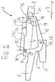
- the mechanism 1 is designed such that a loading of the seat support 4 by a sitting down a user, with a simultaneous pivoting of the coupling element 15, namely a lowering of the front, movable arm 19 of the coupling element 15, a lowering of the front edge 8 and the front part 16 of the seat support 4 has the result, as well as a displacement of the articulation point 17 of the coupling element 15 on the seat support 4 in the seat longitudinal direction 7 to the front, see Fig. 2 ,
- the pivoting resistance of the backrest support 5 and the resulting seat inclination resistance results from the distance L (0) of the points of application of the spring arrangement 22, in this case the seat support pivot axes 12, 17, in the unloaded state.
- the spring elements of the spring arrangement 22 are acted upon in a tilting of the seat support 4 and thus a movement of the seat support 4 relative to the base support 3.
- the tension spring is curious; excited.
- the seat support 4 In this first movement there is no movement of the seat support 4 in the seat longitudinal direction 7.
- the seat support 4 only tilts. From a starting position, in which the seat support 4, more precisely its top 26 and thus the seat mounted thereon (not shown), in the horizontal 23, the seat support 4 by an inclination angle 27, for example, 5 ° relative to the horizontal 23 after inclined forward. If the seat support 4 is in such an inclined position, then the front edge 8 of the seat support 4 is lower than the rear edge 9 of the seat support 4, see Fig. 2 ,
- the seat support 4 Before pivoting the backrest support 5, the seat support 4 is in its non-inclined starting position, in which it is retrieved by the spring assembly 22 when the user stands up or bends backwards for leaning against the backrest.
- the mechanism 1 is designed such that a loading of the backrest support 5 by a leaning of the user to the backrest, with a simultaneous pivoting of the backrest support 5, a lowering of the rear edge 9 and the rear part 11 of the seat support 4th entails, as well as a displacement of the articulation point 17 of the coupling element 15 on the seat support 15 in the seat longitudinal direction 7 to the front, see Fig. 3 , The pivot point 17 of the coupling element 15 on the seat support 4 is further moved in the seat longitudinal direction 7 forward than in the seat tilt position.
- the seat support 4 at the same time performs a movement in the seat longitudinal direction 7 to the rear.
- the seat support 4 is moved backwards down, more specifically pulled by the backrest support 5.
- the seat support 4 is pivoted so that the seat support 4, more precisely its top 26 and thus the seat mounted thereon (not shown), is inclined backwards and relative to the horizontal 23 has an inclination angle 28 of for example 5 °.
- the rear edge 9 of the seat support 4 is therefore lower than the front edge 8 of the seat support 4th
- the spring elements of the spring assembly 22 are acted upon pivoting of the backrest support 5 and thus a movement of the seat support 4 relative to the base support 3 again.
- the distance L (2) of the points 12, 17 of the spring assembly 22 increases with respect to the distance L (0) the unschwenkten position of the backrest support 5 and is also greater than the distance L (1) of the points 12, 17 in the seat tilt position.
- the covered spring travel .DELTA.L L (2) - L (0) is dependent on the tilt angle of the backrest.
- the two base support pivot axes 13, 18 extend coaxially.
- the articulation point 13 of the backrest support 5 on the base support 3 corresponds to the articulation point 18 of the coupling element 15 on the base support 3, see Fig. 1 to 3 ,
- the two base support pivot axes 13, 18 are spaced apart in the seat longitudinal direction 7.
- the articulation point 13 of the backrest support 5 is offset from the base support 3 in the seat longitudinal direction 7 to the articulation point 18 of the coupling element 15 on the base support 3.
- the pivot axes 13, 18 are spaced apart.
- center distance 29 can be by the appropriate choice of the axial distance 29, the ratio of the pivoting resistances, namely the pivotal resistance of the backrest support 5 and the seat inclination resistance of the seat support 4, change. In other words, by a more or less large axial distance 29, a matching of the proportionality of the pivoting resistances to a concrete mechanical design is possible. Thus, the mechanism 1 can be easily preset for certain audiences.
Abstract
Description
- Die Erfindung betrifft eine Mechanik für einen Bürostuhl mit einem auf einer Stuhlsäule plazierbaren Basisträger, mit einem auf dem Basisträger angeordneten, relativ zu dem Basisträger bewegbaren Sitzträger und mit einer mit dem Sitzträger gekoppelten Rückenlehne, wobei ein Verschwenken der Rückenlehne eine Bewegung des Sitzträgers relativ zu dem Basisträger bewirkt.
- Mit einer solchen Mechanik, wie sie als Baugruppe im Sitzunterbau eines Bürostuhles verwendet wird, wird eine Kinematik bereitgestellt, die eine bestimmte Relativbewegung von Sitz und Rückenlehne zueinander mit sich bringt, so daß sich eine korrelierte Sitz-Rückenlehnen-Bewegung ergibt. Dabei werden Sitz und Rückenlehne gemeinsam nach hinten unten verschwenkt.
- Aus dem Stand der Technik sind zahlreiche Lösungen zum Ändern der Bewegungscharakteristik einer solchen Mechanik bekannt, insbesondere zum Verändern des Schwenkwiderstandes der Rückenlehne. Üblicherweise wird mit Hilfe eines Betätigungselements, beispielsweise einer Drehkurbel oder dergleichen, eine Einstellung zwischen "hart" und "weich" gewählt, je nachdem ob es sich bei dem Benutzer des Bürostuhles um eine schwere oder leichte Person handelt.
- Darüber hinaus wird zur weiteren Verbesserung der Ergonomie von Bürostühlen zunehmend eine Einstellbarkeit der Neigung des Sitzes gefordert. Dabei soll der Sitz im belasteten Zustand eine von der waagerechten Position abweichende, leicht nach vorn geneigte Position einnehmen können.
- Der Neigungswiderstand, gegen den sich der Sitzträger bei einem Besitzen des Bürostuhles neigt, ist bei vielen aus dem Stand der Technik bekannten Lösungen nicht veränderbar. Leichte und schwere Personen erfahren daher stets ein und denselben Neigungswiderstand.
- Bei anderen Lösungen ist der Neigungswiderstand des Sitzträgers zwar einstellbar. Dies ist jedoch oftmals konstruktiv aufwendig gelöst. Zusätzliche Bauteile erhöhen die Fertigungs- und Montagekosten und benötigen einen entsprechenden Bauraum.
- Eine Aufgabe der vorliegenden Erfindung ist es, eine alternative Lösung zum Einstellen des Neigungswiderstandes des Sitzträgers eines Bürostuhls anzugeben. Diese Aufgabe wird durch eine Mechanik nach Anspruch 1 gelöst. Vorteilhafte Ausführungen der Erfindung sind in den Unteransprüchen angegeben.
- Eine Grundidee der Erfindung ist es, einen nach vorn aus der Waagerechten heraus gegen die Federkraft einer an dem Sitzträger angreifenden Federanordnung neigbaren Sitzträger vorzusehen, wobei dieselbe Federanordnung auch an dem Rückenlehnenträger angreift. Die für die Einstellung des Schwenkwiderstandes des Rückenlehnenträgers verwendete Federanordnung wird mit anderen Worten für die Einstellung des Neigungswiderstandes des Sitzträgers genutzt. Durch die Wahl der Angriffspunkte der Federanordnung an dem Sitzträger und dem Rückenlehnenträger sowie durch die Wahl geeigneter konstruktiver Ausführungen kann somit auf einfache Weise die Schwenkcharakteristik des Sitzes eingestellt und an die Schwenkcharakteristik der Rückenlehne angepaßt werden.
- Durch eine Änderung der Federkraft-Voreinstellung der Federanordnung wird somit zugleich der Neigungswiderstand des Sitzträgers stärker oder schwächer eingestellt und damit an unterschiedliche Körpergewichte der Benutzer angepaßt.
- Der Sitzträger wird, vorzugsweise unter Verwendung eines geeigneten beweglichen Koppelelements zwischen Basisträger und Sitzträger, bei einem Besitzen des Stuhles in seinem vorderen Bereich gegen die Federkraft der Federanordnung abgesenkt und entsprechend bei einem Entlasten des Sitzes mit Hilfe der Federkraft selbsttätig wieder in seine Ausgangsposition aus- bzw. aufgerichtet. Anders ausgedrückt entsteht bei einem Besitzen des Stuhles und insbesondere bei einem Verlagern des Körpergewichtes auf dem Sitzträger, ein Wippen bzw. Schaukeln des Sitzträgers in die Sitzneigeposition und aus der Sitzneigeposition heraus. Für den Benutzer des Stuhles ergibt sich dadurch ein vergleichsweise "dynamisches" Sitzgefühl.
- Dieses Ein- und Ausfedern in die Sitzneigeposition hinein bzw. aus der Sitzneigeposition heraus wird erfindungsgemäß nicht mit einer eigens dafür zuständigen Feder bewirkt; statt dessen wird die primär für die Rückenlehnenverschwenkung verantwortliche Hauptfeder der Mechanik verwendet. Mit der Erfindung wird also nicht nur eine besonders dynamische Sitzneige-Funktionalität bereitgestellt. Diese Funktionalität wird auch mit minimalem konstruktiven Aufwand erreicht, insbesondere ohne zusätzliche Federelemente. Dadurch verringern sich Herstellungs- und Montageaufwand.
- Besonders vorteilhaft ist es, daß sich eine Voreinstellung der Federkraft der Federanordnung bezüglich des Gewichts des Benutzers unmittelbar auf die Seitzneige-Funktionalität auswirkt. Bei schweren Benutzern, die einen höheren Rückenlehnen-Schwenkwiderstand benötigen, fällt die Federwirkung für die Sitzneigung ebenfalls härter aus, so daß sich automatisch eine stärkere Federwirkung für das Absenken in die Sitzneigeposition ergibt. Je stärker der Schwenkwiderstand der Rückenlehne eingestellt ist, desto stärker wird auch der Neigungswiderstand des Sitzes sein. Somit wird das Wippen oder Schaukeln des Sitzes in die Sitzneigeposition für alle Benutzergewichte gleichermaßen ermöglicht und von allen Benutzern, unabhängig von ihrem Gewicht, gleichermaßen empfunden, sofern die Mechanik, insbesondere die Federanordnung der Mechanik, auf den Benutzer passend eingestellt ist.
- Dabei ist es unerheblich, auf welche Art die Einstellung der Federanordnung erfolgt, beispielsweise manuell und/oder selbsteinstellend in Abhängigkeit von dem Gewicht des Benutzers.
- Die Grundidee der Erfindung ist unabhängig von der konkreten von dem Sitzträger ausgeführten Bewegung relativ zu dem Basisträger. In der Regel handelt es sich bei der Bewegung des Sitzträgers jedoch um eine Bewegung in Sitzlängsrichtung, die von einer Kipp-, Schwenk- und/oder Neigebewegung des Sitzträgers überlagert ist.
- Ausführungsbeispiele der Erfindung werden nachfolgend anhand der Zeichnungen näher erläutert. Hierbei zeigen:
- Fig. 1
- eine Seitenansicht der Mechanik im unbelasteten Zustand,
- Fig. 2
- eine Seitenansicht der Mechanik aus
Fig. 1 mit einem belastetem Sitz, - Fig. 3
- eine Seitenansicht der Mechanik aus
Fig. 1 mit einem belastetem Sitz und einer Belastung der Rückenlehne., - Fig. 4
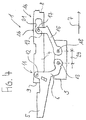
- eine Seitenansicht einer weiteren Mechanik im unbelasteten Zustand.
- Sämtliche Figuren zeigen die Erfindung nicht maßstabsgerecht, dabei lediglich schematisch und nur mit ihren wesentlichen Bestandteilen. Gleiche Bezugszeichen entsprechen dabei Elementen gleicher oder vergleichbarer Funktion.
- In einer bevorzugten Ausführungsform der Erfindung umfaßt die Mechanik 1 für einen Bürostuhl einen mittels einer in
Fig. 1 angedeuteten Konusaufnahme 2 auf das obere Ende einer Stuhlsäule (nicht abgebildet) plazierbaren, vorzugsweise feststehenden Basisträger 3. - Sie umfaßt weiter einen mit dem Basisträger 3 verbundenen, relativ zu dem Basisträger 3 bewegbaren Sitzträger 4, wobei der Sitzträger 4 weder direkt noch unmittelbar mit dem Basisträger 3 verbunden ist. Auf dem Sitzträger 4 ist der in aller Regel mit einer gepolsterten Sitzfläche versehen Sitz (nicht abgebildet) des Bürostuhls montiert.
- Die Mechanik 1 umfaßt weiter einen sowohl mit dem Basisträger 3, als auch mit dem Sitzträger 4 verbundenen, relativ zu dem Basisträger 3 bewegbaren Rückenlehnenträger 5, dessen Verschwenken eine Bewegung des Sitzträgers 4 relativ zu dem Basisträger 3 bewirkt. Die Wangen 6 des in Draufsicht gabelförmigen Rückenlehnenträgers 5 sind zu beiden Seiten des Basisträgers 3 angeordnet.
- Die Mechanik 1 ist bezüglich der Mittellängsebene, was die eigentliche Kinematik betrifft, spiegelsymmetrisch aufgebaut. Insoweit ist bei der folgenden Beschreibung immer von beiderseits paarweise vorhandenen Konstruktionselementen der Mechanik 1 auszugehen.
- "Vorn" oder "vorderes" bedeutet dabei, das ein Bauteil in Sitzlängsrichtung 7 vorn angeordnet ist bzw. bezieht sich auf ein sich in Richtung der vorderen Sitzkante 8 erstreckendes bzw. in diese Richtung weisendes Bauteil, während "hinten" oder "hinteres" bedeutet, das ein Bauteil in Sitzlängsrichtung 7 hinten angeordnet ist bzw. bezieht sich auf ein sich in Richtung der Rückenlehne bzw. des Rückenlehnenträgers 5 bzw. der hinteren Sitzkante 9 erstreckendes bzw. in diese Richtung weisendes Bauteil. Die Angaben "oben" bzw. "unten" beziehen sich auf den bestimmungsgemäßen Verwendungszustand des Bürostuhles bzw. der Bürostuhlmechanik 1.
- In einer bevorzugten Ausführungsform der Erfindung ist der Rückenlehnenträger 5 zur Ausbildung einer ersten Verbindung des Sitzträgers 4 mit dem Basisträger 3 sowohl an einem hinteren Ende 11 des Sitzträgers 4, nämlich mit den freien Enden seiner Wangen 6 in der Nähe der Konusaufnahme 2 unter Ausbildung einer quer zu der Sitzlängsrichtung 7 verlaufenden ersten Sitzträger-Schwenkachse 12, als auch an dem Basisträger 3, nämlich an einem von den Freienden beabstandeten Bereich seiner Wangen 6 unter Ausbildung einer quer zu der Sitzlängsrichtung 7 verlaufenden ersten Basisträger-Schwenkachse 13, verschwenkbar angelenkt, wobei ein Verschwenken des Rückenlehnenträgers 5 in Schwenkrichtung 14 nach hinten unten, d.h. von einer aufrechten Ausgangsstellung in eine hintere Schwenkstellung, eine Bewegung des Sitzträgers 4 relativ zu dem Basisträger 3 bewirkt. Die Art und Weise der Ankopplung des verschwenkbaren Rückenlehnenträgers 5 an den Sitzträger 4 spielt für die vorliegende Erfindung nur eine untergeordnete Rolle. Es kann sich dabei, wie im vorliegenden Fall, um eine direkte oder aber auch eine indirekte Ankopplung handeln.
- Die Mechanik 1 umfaßt darüber hinaus an beiden Seiten des Basisträgers 3, hier in Verlängerung der Wangen 6 des Rückenlehnenträgers 5, angeordnete Koppelelemente 15, die sich von dem Basisträger 3 nach vorn in Richtung der Vorderkante 8 des Sitzträgers 4 erstrecken. Jedes Koppelelement 15 ist zur Ausbildung einer zweiten Verbindung des Sitzträgers 4 mit dem Basisträger 3 sowohl an einem vorderen Ende 16 des Sitzträgers 4, nämlich unter Ausbildung einer quer zu der Sitzlängsrichtung 7 verlaufenden zweiten Sitzträger-Schwenkachse 17, als auch an dem Basisträger 3, nämlich unter Ausbildung einer quer zu der Sitzlängsrichtung 7 verlaufenden zweiten Basisträger-Schwenkachse 18, verschwenkbar angelenkt. Die vorderen Enden der Koppelelemente 15 laufen in zwei zu beiden Seiten des Sitzträgers 4 endenden Armen 19 aus. Dort sind die Koppelelemente 15 beispielsweise mit im Inneren des Sitzträgers 4 angeordneten Konstruktionselementen verbunden, wobei die Verfahrbarkeit der Koppelelemente 15 gegenüber dem Sitzträger 4 in Sitzlängsrichtung 7 durch Öffnungen 21 nach Art von Langlöchern gewährleistet wird. In anderen Fällen sind die Koppelelemente 15 beispielsweise unter Ausbildung von Dreh-/Schiebegelenken mit dem Sitzträger 4 verbunden.
- Damit die Rückenlehne eine definierte Schwenkbewegung vollführen kann, müssen mit der Rückenlehne bzw. dem Rückenlehnenträger 5 unmittelbar oder mittelbar zusammenwirkende Federelemente vorgesehen sein. Durch diese Federelemente wird der Schwenkwiderstand der Rückenlehne bei einem Verschwenken von einer Ausgangsstellung in eine Schwenkstellung sowie die entsprechende Rückstellkraft der Rückenlehne bestimmt. Dementsprechend umfaßt die Mechanik 1 eine zwischen dem Rückenlehnenträger 5 und dem Sitzträger 4 wirkenden Federanordnung 22. Die Art der Federanordnung 22 sowie die Art der möglichen Verstellung der Federanordnung 22 sind für die vorliegende Erfindung nicht ausschlaggebend. Daher ist die Federanordnung 22 in den Figuren lediglich symbolisch angedeutet, siehe
Fig. 1 . So kann es sich bei der Federanordnung 22 beispielsweise in einem einfachen Fall um eine Anzahl von Schraubenfedern handeln. Vorzugsweise handelt es sich um eine oder mehrere Schraubenzugfedern, deren Federenden an den Sitzträger-Schwenkachsen 12, 17 befestigt sind. Es können jedoch auch andere Federelemente oder Federpakete mit mehreren Federelementen zum Einsatz kommen. - Die Angriffspunkte der Federelemente der Federanordnung 22 sind durch ihre Verbindungen mit dem Rückenlehnenträger 5 bzw. dem Sitzträger 4 bestimmt. In einem einfachen Fall sind die Federelemente mit ihren Enden in die Sitzträger-Schwenkachsen 12, 17 eingehängt. Sämtliche Schwenkachsen 12, 13, 17, 18, vorzugsweise jedoch mindestens die Sitzträger-Schwenkachsen 12, 17, sind als physische Achsen ausgebildet.
- Der Sitzträger 4 ist bei einer Belastung des Sitzträgers 4 durch' einen Benutzer relativ zu dem Basisträger 3 gegen die Federkraft der Federanordnung 22 gegenüber der Waagerechten 23 neigbar. Mit anderen Worten greift der Sitzträger 4 während des Neigens an einem ersten Ende 24 der Federanordnung 22 an. Durch das Neigen wird also die Federanordnung 22 beaufschlagt, indem das erste Ende 24 der Federanordnung 22 von dem gegenüberliegenden zweiten Ende 25 der Federanordnung 22 wegbewegt wird.
- Der Rückenlehnenträger 5 ist relativ zu dem Basisträger 3 gegen die Federkraft der Federanordnung 22 verschwenkbar. Anders ausgedrückt greift der Rückenlehnenträger 5 während des Verschwenkens des Rückenlehnenträgers 5 an dem zweiten Ende 25 der Federanordnung 22 an. Die Federanordnung 22, deren Federkraft den Schwenkwiderstand des Rückenlehnenträgers 5 festlegt, bestimmt zusammen mit dem Gewicht des Benutzers die Stärke des Neigens des Sitzträgers 4. Setzt sich ein Benutzer auf den Stuhl, dann neigt sich der Sitzträger 4 gegen die Federkraft der Federanordnung 22. Die Rückstellkraft der Federanordnung 22 bewirkt zugleich ein teilweises oder vollständiges Bewegen des Sitzträgers 4 aus der Sitzneigeposition in seine Ausgangsposition, wenn der Benutzer den Sitzträger teilweise oder vollständig entlastet, also sich entweder auf dem Sitz bewegt oder von dem Sitz aufsteht.
- In der Sitzneigeposition ist das Gewicht des Benutzers in Sitzlängsrichtung nach vorn verlagert. Aufgrund der Gewichtsverlagerung ist ein gleichzeitiges Anlehnen an die Rückenlehne ausgeschlossen. Will sich der Benutzer an die Rückenlehne anlehnen, wird er sein Gewicht zunächst in Sitzlängsrichtung nach hinten verlagern. Der Sitzträger 4 verlagert sich dann erneut in seiner Ausgangsposition. Anders ausgedrückt federt der Sitzträger 4 in seine Ausgangsposition zurück, bevor ein Verschwenken der Rückenlehne erfolgen kann. Mit anderen Worten befindet sich der Sitzträger 4 dann in einer im wesentlichen waagerechten Lage, trotzdem ein Benutzer auf dem Stuhl sitzt. Durch diese mit geeigneten konstruktiven Mitteln erfolgte Abstimmung der Schwenkbewegungen von Sitzträger 4 und Rückenlehnenträger 5 aufeinander und durch das Einführen eines zwangsweise von dem Benutzer zu durchlaufenden neutralen Gleichgewichtszustandes, in dem weder Sitzträger 4 noch Rückenlehnenträger 5 aus ihren Ausgangspositionen heraus verschwenkt sind, wird sichergestellt, daß eine gleichzeitiges Verschwenken von Sitzträger 4 und Rückenlehnenträger 5 ausgeschlossen ist.
- In einer bevorzugten Ausführungsform der Erfindung ist die Federkraft der Federanordnung 22 einstellbar. Vorzugsweise im unbelasteten Zustand, d.h. ohne daß ein Benutzer auf dem Stuhl sitzt, kann eine manuelle Voreinstellung der Federanordnung 22 erfolgen. Ein Ändern der Federkraft-Voreinstellung der Federanordnung 22 ist mit Blick auf ein nachfolgendes Neigen des Sitzträgers 4 von Bedeutung. Durch das Einstellen der Voreinstellung kann nicht nur der Schwenkwiderstand des Rückenlehnenträgers 5, sondern auch der Sitzneigungswiderstand auf einen bestimmten Benutzer, genauer gesagt dessen Gewicht, eingestellt werden. Zugleich ist es auf diese Art und Weise möglich, die Stuhlmechanik 1 auf eine bestimmte Benutzergruppe einzustellen, beispielsweise durch eine entsprechende Einstellung ab Werk. Es kann jedoch auch während des Gebrauchs des Bürostuhles ein mehrmaliger Wechsel der Federkrafteinstellung erfolgen.
- Bei der Vorrichtung zur Änderung der Vorspannung handelt es sich vorzugsweise um eine Einstellvorrichtung mit einem Bahnelement handeln, wie es in der Patentanmeldung
DE 10 2014 104 870.9 beschrieben ist. - Durch die simple Einstellung der Vorspannung der Federanordnung 22 kann, in Verbindung mit einer geeigneten geometrischen Anordnung der einzelnen Bauteile der Mechanik 1 zueinander, insbesondere der Anordnung der Anlenkpunkte und Schwenkachsen 12, 13, 17, 18, insbesondere deren Abstand zueinander, auf besonders einfache Weise die gesamte Synchronbewegung der Bürostuhlmechanik 1 eingestellt und der gewünschte neutrale Gleichgewichtszustand zwischen einer Sitzneigung und einer Verschwenkung der Rückenlehne erreicht werden.
- In einer bevorzugten Ausführungsform der Erfindung wirkt die Federanordnung 22 zwischen den Sitzträger-Schwenkachsen 12, 17. Die Enden 24, 25 der verwendeten Federelemente greifen mit anderen Worten an den Sitzträger-Schwenkachsen 12, 17 an.
- In einer bevorzugten Ausführungsform der Erfindung ist die Lage der zweiten Sitzträger-Schwenkachse 17, und damit die Lage des Anlenkpunktes des Koppelelements 15 an den Sitzträger 4, in Sitzlängsrichtung 7 veränderbar, nämlich bei einem Neigen des Sitzträgers 4 und/oder bei einem Verschwenken des Rückenlehnenträgers 5 in Schwenkrichtung 14.
- In einer bevorzugten Ausführungsform der Erfindung ist die Mechanik 1 derart ausgeführt, daß ein Belasten des Sitzträgers 4 durch ein Hinsetzen eines Benutzers, bei einem gleichzeitigen Verschwenken des Koppelelements 15, nämlich einem Absenken des vorderen, beweglichen Armes 19 des Koppelelementes 15, ein Absenken der Vorderkante 8 bzw. des vorderen Teils 16 des Sitzträgers 4 zur Folge hat, sowie ein Verschieben des Anlenkpunktes 17 des Koppelelements 15 an dem Sitzträger 4 in Sitzlängsrichtung 7 nach vorne, siehe
Fig. 2 . - Der Schwenkwiderstand des Rückenlehnenträgers 5 sowie der daraus resultierende Sitzneigungswiderstand ergibt sich aus dem Abstand L(0) der Angriffspunkte der Federanordnung 22, hier also der Sitzträger-Schwenkachsen 12, 17, im unbelasteten Zustand.
- Die Federelemente der Federanordnung 22 werden bei einem Neigen des Sitzträgers 4 und damit einer Bewegung des Sitzträgers 4 relativ zu dem Basisträger 3 beaufschlagt. Die Zugfeder wird gespannt. Der hierbei zurückgelegte Federweg ΔL = L(1)- L(0) ist von der voreingestellten Vorspannung der Federanordnung 22 sowie von dem Gewicht des Benutzers abhängig.
- Bei dieser ersten Bewegung erfolgt keine Bewegung des Sitzträgers 4 in Sitzlängsrichtung 7. Der Sitzträger 4 neigt sich lediglich. Aus einer Ausgangsposition, in der sich der Sitzträger 4, genauer gesagt dessen Oberseite 26 und damit der darauf montierte Sitz (nicht abgebildet), in der Waagerechten 23 befindet, wird der Sitzträger 4 um einen Neigungswinkel 27 von beispielsweise 5° gegenüber der Waagerechten 23 nach vorn geneigt. Befindet sich der Sitzträger 4 in einer solchen geneigten Position, dann ist die Vorderkante 8 des Sitzträgers 4 niedriger als die Hinterkante 9 des Sitzträgers 4, siehe
Fig. 2 . - Vor einem Verschwenken des Rückenlehnenträgers 5 befindet sich der Sitzträger 4 in seiner nichtgeneigten Ausgangsposition, in die er durch die Federanordnung 22 zurückgeholt wird, wenn sich der Benutzer aufrichtet bzw. sich nach hinten beugt zum Anlehnen an die Rückenlehne.
- In einer bevorzugten Ausführungsform der Erfindung ist die Mechanik 1 derart ausgeführt, daß ein Belasten des Rückenlehnenträgers 5 durch ein Anlehnen des Benutzers an die Rückenlehne, bei einem gleichzeitigen Verschwenken des Rückenlehnenträgers 5, ein Absenken der Hinterkante 9 bzw. des hinteren Teils 11 des Sitzträgers 4 zur Folge hat, sowie ein Verschieben des Anlenkpunktes 17 des Koppelelements 15 an dem Sitzträger 15 in Sitzlängsrichtung 7 nach vorne, siehe
Fig. 3 . Der Anlenkpunkt 17 des Koppelelements 15 an dem Sitzträger 4 ist dabei weiter in Sitzlängsrichtung 7 nach vorn verschoben, als in der Sitzneigeposition. - Hierbei vollführt der Sitzträger 4 zugleich eine Bewegung in Sitzlängsrichtung 7 nach hinten. Mit anderen Worten wird der Sitzträger 4 nach hinten unten verfahren, genauer gesagt von dem Rückenlehnenträger 5 gezogen. Der Sitzträger 4 wird dabei derart verschwenkt, daß der Sitzträger 4, genauer gesagt dessen Oberseite 26 und damit der darauf montierte Sitz (nicht abgebildet), nach hinten geneigt ist und gegenüber der Waagerechten 23 einen Neigungswinkel 28 von beispielsweise 5° aufweist. Im maximal nach hinten verschwenkten Zustand des Rückenlehnenträgers 5 ist die Hinterkante 9 des Sitzträgers 4 daher niedriger als die Vorderkante 8 des Sitzträgers 4.
- Die Federelemente der Federanordnung 22 werden bei einem Verschwenken des Rückenlehnenträgers 5 und damit einer Bewegung des Sitzträgers 4 relativ zu dem Basisträger 3 erneut beaufschlagt. Der Abstand L(2) der Angriffspunkte 12, 17 der Federanordnung 22 nimmt gegenüber dem Abstand L(0) der unverschwenkten Stellung des Rückenlehnenträgers 5 zu und ist auch größer als der Abstand L(1) der Angriffspunkte 12, 17 in der Sitzneigeposition. Der zurückgelegte Federweg ΔL = L(2)- L(0) ist von dem Schwenkwinkel der Rückenlehne abhängig.
- In einer bevorzugten Ausführungsform der Erfindung verlaufen die beiden Basisträger-Schwenkachsen 13, 18 koaxial. Mit anderen Worten entspricht der Anlenkpunkt 13 des Rückenlehnenträgers 5 an dem Basisträger 3 dem Anlenkpunkt 18 des Koppelelements 15 an dem Basisträger 3, siehe
Fig. 1 bis 3 . - Ist der Achsabstand 29 gleich Null, liegt also am Basisträger 3 lediglich eine einzige gemeinsame Drehachse 13, 18 vor, ergibt sich eine konstruktiv besonders einfach aufgebaute Mechanik 1. In einer hierzu alternativen anderen bevorzugten Ausführungsform der Erfindung sind die beiden Basisträgers-Schwenkachsen 13, 18 in Sitzlängsrichtung 7 voneinander beabstandet. Mit anderen Worten ist der Anlenkpunkt 13 des Rückenlehnenträgers 5 an dem Basisträger 3 in Sitzlängsrichtung 7 zu dem Anlenkpunkt 18 des Koppelelements 15 an dem Basisträger 3 versetzt angeordnet. Die Schwenkachsen 13, 18 sind voneinander beabstandet.
- Bei vorhandenem Achsabstand 29 läßt sich durch die geeignete Wahl des Achsabstandes 29 das Verhältnis der Schwenkwiderstände, nämlich des Schwenkwiderstandes des Rückenlehnenträgers 5 und des Sitzneigungswiderstandes des Sitzträgers 4, verändern. Durch einen mehr oder weniger großen Achsabstand 29 ist anders ausgedrückt eine Abstimmung der Proportionalität der Schwenkwiderstände auf ein konkretes Mechanikdesign möglich. So kann die Mechanik 1 besonders einfach für bestimmte Zielgruppen voreingestellt werden.
- Alle in der Beschreibung, den nachfolgenden Ansprüchen und der Zeichnung dargestellten Merkmale können sowohl einzeln als auch in beliebiger Kombination miteinander erfindungswesentlich sein.
-
- 1
- Mechanik
- 2
- Konusaufnahme
- 3
- Basisträger
- 4
- Sitzträger
- 5
- Rückenlehnenträger
- 6
- Wange
- 7
- Sitzlängsrichtung
- 8
- Vordere Sitzkante
- 9
- Hintere Sitzkante
- 10
- (frei)
- 11
- hinteres Ende des Sitzträgers
- 12
- erste Sitzträger-Schwenkachse
- 13
- erste Basisträger-Schwenkachse
- 14
- Schwenkrichtung
- 15
- Koppelelement
- 16
- vorderes Ende des Sitzträgers
- 17
- zweite Sitzträger-Schwenkachse
- 18
- zweite Basisträger-Schwenkachse
- 19
- vorderes Ende des Koppelelements
- 20
- (frei)
- 21
- Öffnung
- 22
- Federanordnung
- 23
- Waagerechte
- 24
- erstes Ende der Federanordnung, erster Angriffspunkt
- 25
- zweites Ende der Federanordnung, zweiter Angriffspunkt
- 26
- Oberseite des Sitzträgers
- 27
- erster Neigungswinkel
- 28
- zweiter Neigungswinkel
- 29
- Achsabstand
Claims (10)
- Mechanik (1) für einen Bürostuhl,- mit einem auf einer Stuhlsäule plazierbaren Basisträger (3),- mit einem mit dem Basisträger (3) verbundenen, relativ zu dem Basisträger (3) bewegbaren Sitzträger (4),- mit einem sowohl mit dem Basisträger (3), als auch mit dem Sitzträger (4) verbundenen, relativ zu dem Basisträger (3) bewegbaren Rückenlehnenträger (5), dessen Verschwenken eine Bewegung des Sitzträgers (4) relativ zu dem Basisträger (3) bewirkt, und- mit einer zwischen dem Rückenlehnenträger (5) und dem Sitzträger (4) wirkenden Federanordnung (22) zur Festlegung des Schwenkwiderstandes des Rückenlehnenträgers (5), wobei der Rückenlehnenträger (5) relativ zu dem Basisträger (3) gegen die Federkraft der Federanordnung (22) verschwenkbar ist,dadurch gekennzeichnet, daß der Sitzträger (4) relativ zu dem Basisträger (3) gegen die Federkraft der Federanordnung (22) neigbar ist und die Federanordnung zugleich den Neigungswiderstand des Sitzträgers (4) festlegt.
- Mechanik (1) nach Anspruch 1, wobei die Federkraft der Federanordnung (22) einstellbar ist, wodurch gleichzeitig der Schwenkwiderstandes des Rückenlehnenträgers (5) und der Neigungswiderstand des Sitzträgers (4) veränderbar sind.
- Mechanik (1) nach Anspruch 1 oder 2, wobei die Mechanik (1) ein Basisträger (3) und Sitzträger (4) beweglich miteinander verbindbares Koppelelement (15) aufweist.
- Mechanik (1) nach Anspruch 3,
wobei der Rückenlehnenträger (5)sowohl an einem hinteren Ende (11) des Sitzträgers (4), dies unter Ausbildung einer quer zu der Sitzlängsrichtung (7) verlaufenden ersten Sitzträger-Schwenkachse (12),als auch an dem Basisträger (3), dies unter Ausbildung einer quer zu der Sitzlängsrichtung (7) verlaufenden ersten Basisträger-Schwenkachse (13),angelenkt ist, wobei ein Verschwenken des Rückenlehnenträgers (5) eine Bewegung des Sitzträgers (4) relativ zu dem Basisträger (3) bewirkt,
und wobei das Koppelelement (15)sowohl an einem vorderen Ende (16) des Sitzträgers (4), dies unter Ausbildung einer quer zu der Sitzlängsrichtung (7) verlaufenden zweiten Sitzträger-Schwenkachse (17),als auch an dem Basisträger (3), dies unter Ausbildung einer quer zu der Sitzlängsrichtung (7) verlaufenden zweiten Basisträger-Schwenkachse (18), angelenkt ist. - Mechanik (1) nach Anspruch 4, wobei die Federanordnung (22) zwischen den Sitzträger-Schwenkachsen (12, 17) wirkt.
- Mechanik (1) nach Anspruch 4 oder 5, wobei die Lage der zweiten Sitzträger-Schwenkachse (17) bei einem Neigen des Sitzträgers (4) und/oder bei einem Verschwenken des Rückenlehnenträgers (5) in Sitzlängsrichtung (7) veränderbar ist.
- Mechanik (1) nach Anspruch 6, bei der ein Belasten des Sitzträgers (4) ein Absenken der Vorderkante (8) des Sitzträgers (4) zur Folge hat, sowie ein Verschieben des Anlenkpunktes (17) des Koppelelements (15) an dem Sitzträger (4) in Sitzlängsrichtung (7) nach vorne.
- Mechanik (1) nach Anspruch 6 oder 7, bei der ein Belasten des Rückenlehnenträgers (5) ein Absenken der Hinterkante (9) des Sitzträgers (4) zur Folge hat, sowie ein Verschieben des Anlenkpunktes (17) des Koppelelements (15) an dem Sitzträger (4) in Sitzlängsrichtung (7) nach vorne.
- Mechanik (1) nach einem der Ansprüche 4 bis 8, wobei die beiden Basisträger-Schwenkachsen (13, 18) koaxial verlaufen.
- Mechanik (1) nach einem der Ansprüche 4 bis 8, wobei die beiden Basisträgers-Schwenkachsen (13, 18) in Sitzlängsrichtung (7) voneinander beabstandet sind.
Applications Claiming Priority (1)
| Application Number | Priority Date | Filing Date | Title |
|---|---|---|---|
| DE102015111946.3A DE102015111946A1 (de) | 2015-07-22 | 2015-07-22 | Mechanik für einen Bürostuhl |
Publications (2)
| Publication Number | Publication Date |
|---|---|
| EP3120732A1 true EP3120732A1 (de) | 2017-01-25 |
| EP3120732B1 EP3120732B1 (de) | 2020-12-30 |
Family
ID=56360149
Family Applications (1)
| Application Number | Title | Priority Date | Filing Date |
|---|---|---|---|
| EP16001495.7A Active EP3120732B1 (de) | 2015-07-22 | 2016-07-05 | Mechanik für einen bürostuhl |
Country Status (3)
| Country | Link |
|---|---|
| US (1) | US10143306B2 (de) |
| EP (1) | EP3120732B1 (de) |
| DE (1) | DE102015111946A1 (de) |
Cited By (3)
| Publication number | Priority date | Publication date | Assignee | Title |
|---|---|---|---|---|
| US20180289159A1 (en) * | 2017-04-10 | 2018-10-11 | Bock 1 Gmbh & Co. Kg | Synchronized mechanism for an office chair |
| US20180332967A1 (en) * | 2016-09-01 | 2018-11-22 | Ue Furniture Co., Ltd | Seat structure and chair |
| US11350750B2 (en) | 2018-04-17 | 2022-06-07 | L&P Property Management Company | Tilt mechanism for a chair and chair |
Families Citing this family (2)
| Publication number | Priority date | Publication date | Assignee | Title |
|---|---|---|---|---|
| US10098890B2 (en) * | 2016-10-29 | 2018-10-16 | Cipla Limited | Stable carfilzomib formulations |
| US11957246B2 (en) | 2020-07-22 | 2024-04-16 | Formway Furniture Limited | Chair |
Citations (4)
| Publication number | Priority date | Publication date | Assignee | Title |
|---|---|---|---|---|
| JPH0231530U (de) * | 1988-08-22 | 1990-02-28 | ||
| US6234573B1 (en) * | 1998-05-27 | 2001-05-22 | Peter Röder | Chair, in particular office chair |
| CH702970A2 (de) * | 2010-04-07 | 2011-10-14 | Sitag Ag | Stuhl mit Sitzplatte und Rückenlehne. |
| DE102014104870A1 (de) | 2014-04-04 | 2015-10-08 | Bock 1 Gmbh & Co. Kg | Mechanik für einen Bürostuhl |
Family Cites Families (13)
| Publication number | Priority date | Publication date | Assignee | Title |
|---|---|---|---|---|
| US4966411A (en) * | 1987-10-24 | 1990-10-30 | Kokuyo Co., Ltd. | Chair provided with a backrest |
| DE3930983C2 (de) * | 1989-09-16 | 1993-09-30 | Rolf Voelkle | Sitzmöbel mit neigungsverstellbarer Sitzfläche |
| EP0485868A1 (de) * | 1990-11-14 | 1992-05-20 | Giroflex-Entwicklungs AG | Stuhl, insbesondere Bürostuhl |
| IL103477A0 (en) * | 1992-10-20 | 1993-03-15 | Paltechnica Nitzanim | Office and like chairs |
| GB9802447D0 (en) * | 1998-02-04 | 1998-04-01 | Unit Press Limited | Mechanism for chair |
| DE10122948C1 (de) * | 2001-05-11 | 2003-03-13 | Armin Sander | Stuhl, insbesondere Bürostuhl |
| DE10122945A1 (de) * | 2001-05-11 | 2002-12-12 | Armin Sander | Stuhl, insbesondere Bürostuhl |
| DE202006018268U1 (de) * | 2006-12-04 | 2007-02-08 | Sato Office Gmbh | Sitz mit einer Sitzplatte und einer Rückenlehne |
| DE102008011309B3 (de) * | 2008-02-27 | 2009-06-04 | Thonet Gmbh | Bürostuhl |
| US7922247B2 (en) * | 2008-04-18 | 2011-04-12 | Spark Innovations, Inc. | Hydraulic adjustable seat |
| US8646839B2 (en) * | 2008-06-17 | 2014-02-11 | Co.Fe.Mo. Industrie S.R.L. | Adjustment device for chairs |
| US9060612B2 (en) * | 2011-05-17 | 2015-06-23 | Rebecca M. Lee | Balance chair |
| EP2896325B1 (de) * | 2014-01-20 | 2018-02-28 | L&P Property Management Company | Kippvorrichtung für ein Sitzmöbel und Sitzmöbel damit |
-
2015
- 2015-07-22 DE DE102015111946.3A patent/DE102015111946A1/de not_active Withdrawn
-
2016
- 2016-07-05 EP EP16001495.7A patent/EP3120732B1/de active Active
- 2016-07-22 US US15/217,250 patent/US10143306B2/en active Active
Patent Citations (4)
| Publication number | Priority date | Publication date | Assignee | Title |
|---|---|---|---|---|
| JPH0231530U (de) * | 1988-08-22 | 1990-02-28 | ||
| US6234573B1 (en) * | 1998-05-27 | 2001-05-22 | Peter Röder | Chair, in particular office chair |
| CH702970A2 (de) * | 2010-04-07 | 2011-10-14 | Sitag Ag | Stuhl mit Sitzplatte und Rückenlehne. |
| DE102014104870A1 (de) | 2014-04-04 | 2015-10-08 | Bock 1 Gmbh & Co. Kg | Mechanik für einen Bürostuhl |
Cited By (5)
| Publication number | Priority date | Publication date | Assignee | Title |
|---|---|---|---|---|
| US20180332967A1 (en) * | 2016-09-01 | 2018-11-22 | Ue Furniture Co., Ltd | Seat structure and chair |
| US10595636B2 (en) * | 2016-09-01 | 2020-03-24 | Ue Furniture Co., Ltd | Seat structure and chair |
| US20180289159A1 (en) * | 2017-04-10 | 2018-10-11 | Bock 1 Gmbh & Co. Kg | Synchronized mechanism for an office chair |
| US10610019B2 (en) * | 2017-04-10 | 2020-04-07 | Bock 1 Gmbh & Co. Kg | Synchronized mechanism for an office chair |
| US11350750B2 (en) | 2018-04-17 | 2022-06-07 | L&P Property Management Company | Tilt mechanism for a chair and chair |
Also Published As
| Publication number | Publication date |
|---|---|
| US10143306B2 (en) | 2018-12-04 |
| US20170020290A1 (en) | 2017-01-26 |
| EP3120732B1 (de) | 2020-12-30 |
| DE102015111946A1 (de) | 2017-01-26 |
Similar Documents
| Publication | Publication Date | Title |
|---|---|---|
| EP0635227B1 (de) | Stuhl, insbesondere Bürostuhl | |
| EP1712410B1 (de) | Fahrzeugsitz mit verformbarer Rückenlehne | |
| EP1454568B1 (de) | Stuhl, insbesondere Bürostuhl | |
| EP3120732B1 (de) | Mechanik für einen bürostuhl | |
| CH636252A5 (de) | Ergonomischer stuhl. | |
| WO2011141107A1 (de) | Verstellmechanik zur einstellung einer auf eine rückenlehne eines stuhls einwirkende rückstellkraft und bürostuhl mit einer solchen verstellmechanik | |
| EP3019047B1 (de) | Mechanik für einen bürostuhl | |
| DE102004053965B4 (de) | Stuhl | |
| DE60221793T2 (de) | Stühle | |
| DE19902467A1 (de) | Sessel mit Aufstehhilfe | |
| EP3263396A1 (de) | Federungsvorrichtung | |
| EP3345507B1 (de) | Mechanik für einen stuhl | |
| DE202009009612U1 (de) | Stuhl | |
| DE10123231C2 (de) | Bürostuhl | |
| EP3973820A1 (de) | Mechanik für einen stuhl | |
| EP3528664B1 (de) | Synchronstuhlmechanik und stuhl mit einer solchen | |
| DE202020104509U1 (de) | Sitz- und Liegemöbel | |
| EP2477523B1 (de) | Wippmechanik für einen bürostuhl | |
| EP0341344B1 (de) | Sitzmöbel | |
| EP2173218B1 (de) | Stuhl, insbesondere bürostuhl | |
| DE69722986T2 (de) | Verstellbarer Bürostuhl | |
| EP3403534B1 (de) | Sitzvorrichtung | |
| DE102020103680A1 (de) | Armlehne, insbesondere für einen Bürostuhl | |
| WO2024013141A1 (de) | Synchronmechanik für einen stuhl | |
| DE102004050854B4 (de) | Stuhl |
Legal Events
| Date | Code | Title | Description |
|---|---|---|---|
| PUAI | Public reference made under article 153(3) epc to a published international application that has entered the european phase |
Free format text: ORIGINAL CODE: 0009012 |
|
| STAA | Information on the status of an ep patent application or granted ep patent |
Free format text: STATUS: THE APPLICATION HAS BEEN PUBLISHED |
|
| AK | Designated contracting states |
Kind code of ref document: A1 Designated state(s): AL AT BE BG CH CY CZ DE DK EE ES FI FR GB GR HR HU IE IS IT LI LT LU LV MC MK MT NL NO PL PT RO RS SE SI SK SM TR |
|
| AX | Request for extension of the european patent |
Extension state: BA ME |
|
| STAA | Information on the status of an ep patent application or granted ep patent |
Free format text: STATUS: REQUEST FOR EXAMINATION WAS MADE |
|
| 17P | Request for examination filed |
Effective date: 20170719 |
|
| RBV | Designated contracting states (corrected) |
Designated state(s): AL AT BE BG CH CY CZ DE DK EE ES FI FR GB GR HR HU IE IS IT LI LT LU LV MC MK MT NL NO PL PT RO RS SE SI SK SM TR |
|
| STAA | Information on the status of an ep patent application or granted ep patent |
Free format text: STATUS: EXAMINATION IS IN PROGRESS |
|
| 17Q | First examination report despatched |
Effective date: 20180423 |
|
| GRAP | Despatch of communication of intention to grant a patent |
Free format text: ORIGINAL CODE: EPIDOSNIGR1 |
|
| STAA | Information on the status of an ep patent application or granted ep patent |
Free format text: STATUS: GRANT OF PATENT IS INTENDED |
|
| INTG | Intention to grant announced |
Effective date: 20200825 |
|
| GRAS | Grant fee paid |
Free format text: ORIGINAL CODE: EPIDOSNIGR3 |
|
| GRAA | (expected) grant |
Free format text: ORIGINAL CODE: 0009210 |
|
| STAA | Information on the status of an ep patent application or granted ep patent |
Free format text: STATUS: THE PATENT HAS BEEN GRANTED |
|
| AK | Designated contracting states |
Kind code of ref document: B1 Designated state(s): AL AT BE BG CH CY CZ DE DK EE ES FI FR GB GR HR HU IE IS IT LI LT LU LV MC MK MT NL NO PL PT RO RS SE SI SK SM TR |
|
| REG | Reference to a national code |
Ref country code: GB Ref legal event code: FG4D Free format text: NOT ENGLISH |
|
| REG | Reference to a national code |
Ref country code: AT Ref legal event code: REF Ref document number: 1349073 Country of ref document: AT Kind code of ref document: T Effective date: 20210115 |
|
| REG | Reference to a national code |
Ref country code: DE Ref legal event code: R096 Ref document number: 502016012050 Country of ref document: DE |
|
| REG | Reference to a national code |
Ref country code: IE Ref legal event code: FG4D Free format text: LANGUAGE OF EP DOCUMENT: GERMAN |
|
| PG25 | Lapsed in a contracting state [announced via postgrant information from national office to epo] |
Ref country code: GR Free format text: LAPSE BECAUSE OF FAILURE TO SUBMIT A TRANSLATION OF THE DESCRIPTION OR TO PAY THE FEE WITHIN THE PRESCRIBED TIME-LIMIT Effective date: 20210331 Ref country code: NO Free format text: LAPSE BECAUSE OF FAILURE TO SUBMIT A TRANSLATION OF THE DESCRIPTION OR TO PAY THE FEE WITHIN THE PRESCRIBED TIME-LIMIT Effective date: 20210330 Ref country code: RS Free format text: LAPSE BECAUSE OF FAILURE TO SUBMIT A TRANSLATION OF THE DESCRIPTION OR TO PAY THE FEE WITHIN THE PRESCRIBED TIME-LIMIT Effective date: 20201230 Ref country code: FI Free format text: LAPSE BECAUSE OF FAILURE TO SUBMIT A TRANSLATION OF THE DESCRIPTION OR TO PAY THE FEE WITHIN THE PRESCRIBED TIME-LIMIT Effective date: 20201230 |
|
| PG25 | Lapsed in a contracting state [announced via postgrant information from national office to epo] |
Ref country code: LV Free format text: LAPSE BECAUSE OF FAILURE TO SUBMIT A TRANSLATION OF THE DESCRIPTION OR TO PAY THE FEE WITHIN THE PRESCRIBED TIME-LIMIT Effective date: 20201230 Ref country code: SE Free format text: LAPSE BECAUSE OF FAILURE TO SUBMIT A TRANSLATION OF THE DESCRIPTION OR TO PAY THE FEE WITHIN THE PRESCRIBED TIME-LIMIT Effective date: 20201230 Ref country code: BG Free format text: LAPSE BECAUSE OF FAILURE TO SUBMIT A TRANSLATION OF THE DESCRIPTION OR TO PAY THE FEE WITHIN THE PRESCRIBED TIME-LIMIT Effective date: 20210330 |
|
| REG | Reference to a national code |
Ref country code: NL Ref legal event code: MP Effective date: 20201230 |
|
| PG25 | Lapsed in a contracting state [announced via postgrant information from national office to epo] |
Ref country code: HR Free format text: LAPSE BECAUSE OF FAILURE TO SUBMIT A TRANSLATION OF THE DESCRIPTION OR TO PAY THE FEE WITHIN THE PRESCRIBED TIME-LIMIT Effective date: 20201230 |
|
| REG | Reference to a national code |
Ref country code: LT Ref legal event code: MG9D |
|
| PG25 | Lapsed in a contracting state [announced via postgrant information from national office to epo] |
Ref country code: LT Free format text: LAPSE BECAUSE OF FAILURE TO SUBMIT A TRANSLATION OF THE DESCRIPTION OR TO PAY THE FEE WITHIN THE PRESCRIBED TIME-LIMIT Effective date: 20201230 Ref country code: NL Free format text: LAPSE BECAUSE OF FAILURE TO SUBMIT A TRANSLATION OF THE DESCRIPTION OR TO PAY THE FEE WITHIN THE PRESCRIBED TIME-LIMIT Effective date: 20201230 Ref country code: EE Free format text: LAPSE BECAUSE OF FAILURE TO SUBMIT A TRANSLATION OF THE DESCRIPTION OR TO PAY THE FEE WITHIN THE PRESCRIBED TIME-LIMIT Effective date: 20201230 Ref country code: CZ Free format text: LAPSE BECAUSE OF FAILURE TO SUBMIT A TRANSLATION OF THE DESCRIPTION OR TO PAY THE FEE WITHIN THE PRESCRIBED TIME-LIMIT Effective date: 20201230 Ref country code: PT Free format text: LAPSE BECAUSE OF FAILURE TO SUBMIT A TRANSLATION OF THE DESCRIPTION OR TO PAY THE FEE WITHIN THE PRESCRIBED TIME-LIMIT Effective date: 20210430 Ref country code: RO Free format text: LAPSE BECAUSE OF FAILURE TO SUBMIT A TRANSLATION OF THE DESCRIPTION OR TO PAY THE FEE WITHIN THE PRESCRIBED TIME-LIMIT Effective date: 20201230 Ref country code: SK Free format text: LAPSE BECAUSE OF FAILURE TO SUBMIT A TRANSLATION OF THE DESCRIPTION OR TO PAY THE FEE WITHIN THE PRESCRIBED TIME-LIMIT Effective date: 20201230 |
|
| PG25 | Lapsed in a contracting state [announced via postgrant information from national office to epo] |
Ref country code: PL Free format text: LAPSE BECAUSE OF FAILURE TO SUBMIT A TRANSLATION OF THE DESCRIPTION OR TO PAY THE FEE WITHIN THE PRESCRIBED TIME-LIMIT Effective date: 20201230 |
|
| PG25 | Lapsed in a contracting state [announced via postgrant information from national office to epo] |
Ref country code: IS Free format text: LAPSE BECAUSE OF FAILURE TO SUBMIT A TRANSLATION OF THE DESCRIPTION OR TO PAY THE FEE WITHIN THE PRESCRIBED TIME-LIMIT Effective date: 20210430 |
|
| REG | Reference to a national code |
Ref country code: DE Ref legal event code: R097 Ref document number: 502016012050 Country of ref document: DE |
|
| PG25 | Lapsed in a contracting state [announced via postgrant information from national office to epo] |
Ref country code: AL Free format text: LAPSE BECAUSE OF FAILURE TO SUBMIT A TRANSLATION OF THE DESCRIPTION OR TO PAY THE FEE WITHIN THE PRESCRIBED TIME-LIMIT Effective date: 20201230 |
|
| PLBE | No opposition filed within time limit |
Free format text: ORIGINAL CODE: 0009261 |
|
| STAA | Information on the status of an ep patent application or granted ep patent |
Free format text: STATUS: NO OPPOSITION FILED WITHIN TIME LIMIT |
|
| PG25 | Lapsed in a contracting state [announced via postgrant information from national office to epo] |
Ref country code: ES Free format text: LAPSE BECAUSE OF FAILURE TO SUBMIT A TRANSLATION OF THE DESCRIPTION OR TO PAY THE FEE WITHIN THE PRESCRIBED TIME-LIMIT Effective date: 20201230 Ref country code: DK Free format text: LAPSE BECAUSE OF FAILURE TO SUBMIT A TRANSLATION OF THE DESCRIPTION OR TO PAY THE FEE WITHIN THE PRESCRIBED TIME-LIMIT Effective date: 20201230 |
|
| 26N | No opposition filed |
Effective date: 20211001 |
|
| PG25 | Lapsed in a contracting state [announced via postgrant information from national office to epo] |
Ref country code: SI Free format text: LAPSE BECAUSE OF FAILURE TO SUBMIT A TRANSLATION OF THE DESCRIPTION OR TO PAY THE FEE WITHIN THE PRESCRIBED TIME-LIMIT Effective date: 20201230 |
|
| REG | Reference to a national code |
Ref country code: CH Ref legal event code: PL |
|
| GBPC | Gb: european patent ceased through non-payment of renewal fee |
Effective date: 20210705 |
|
| PG25 | Lapsed in a contracting state [announced via postgrant information from national office to epo] |
Ref country code: MC Free format text: LAPSE BECAUSE OF FAILURE TO SUBMIT A TRANSLATION OF THE DESCRIPTION OR TO PAY THE FEE WITHIN THE PRESCRIBED TIME-LIMIT Effective date: 20201230 |
|
| REG | Reference to a national code |
Ref country code: BE Ref legal event code: MM Effective date: 20210731 |
|
| PG25 | Lapsed in a contracting state [announced via postgrant information from national office to epo] |
Ref country code: LI Free format text: LAPSE BECAUSE OF NON-PAYMENT OF DUE FEES Effective date: 20210731 Ref country code: GB Free format text: LAPSE BECAUSE OF NON-PAYMENT OF DUE FEES Effective date: 20210705 Ref country code: CH Free format text: LAPSE BECAUSE OF NON-PAYMENT OF DUE FEES Effective date: 20210731 |
|
| PG25 | Lapsed in a contracting state [announced via postgrant information from national office to epo] |
Ref country code: IS Free format text: LAPSE BECAUSE OF FAILURE TO SUBMIT A TRANSLATION OF THE DESCRIPTION OR TO PAY THE FEE WITHIN THE PRESCRIBED TIME-LIMIT Effective date: 20210430 Ref country code: LU Free format text: LAPSE BECAUSE OF NON-PAYMENT OF DUE FEES Effective date: 20210705 Ref country code: FR Free format text: LAPSE BECAUSE OF NON-PAYMENT OF DUE FEES Effective date: 20210731 |
|
| PG25 | Lapsed in a contracting state [announced via postgrant information from national office to epo] |
Ref country code: IE Free format text: LAPSE BECAUSE OF NON-PAYMENT OF DUE FEES Effective date: 20210705 Ref country code: BE Free format text: LAPSE BECAUSE OF NON-PAYMENT OF DUE FEES Effective date: 20210731 |
|
| REG | Reference to a national code |
Ref country code: AT Ref legal event code: MM01 Ref document number: 1349073 Country of ref document: AT Kind code of ref document: T Effective date: 20210705 |
|
| PG25 | Lapsed in a contracting state [announced via postgrant information from national office to epo] |
Ref country code: AT Free format text: LAPSE BECAUSE OF NON-PAYMENT OF DUE FEES Effective date: 20210705 |
|
| PG25 | Lapsed in a contracting state [announced via postgrant information from national office to epo] |
Ref country code: HU Free format text: LAPSE BECAUSE OF FAILURE TO SUBMIT A TRANSLATION OF THE DESCRIPTION OR TO PAY THE FEE WITHIN THE PRESCRIBED TIME-LIMIT; INVALID AB INITIO Effective date: 20160705 |
|
| PG25 | Lapsed in a contracting state [announced via postgrant information from national office to epo] |
Ref country code: CY Free format text: LAPSE BECAUSE OF FAILURE TO SUBMIT A TRANSLATION OF THE DESCRIPTION OR TO PAY THE FEE WITHIN THE PRESCRIBED TIME-LIMIT Effective date: 20201230 |
|
| PG25 | Lapsed in a contracting state [announced via postgrant information from national office to epo] |
Ref country code: SM Free format text: LAPSE BECAUSE OF FAILURE TO SUBMIT A TRANSLATION OF THE DESCRIPTION OR TO PAY THE FEE WITHIN THE PRESCRIBED TIME-LIMIT Effective date: 20201230 |
|
| PGFP | Annual fee paid to national office [announced via postgrant information from national office to epo] |
Ref country code: IT Payment date: 20230606 Year of fee payment: 8 |
|
| PGFP | Annual fee paid to national office [announced via postgrant information from national office to epo] |
Ref country code: DE Payment date: 20230628 Year of fee payment: 8 |