EP3120421B1 - Elektrische anschlussklemme - Google Patents
Elektrische anschlussklemme Download PDFInfo
- Publication number
- EP3120421B1 EP3120421B1 EP15710490.2A EP15710490A EP3120421B1 EP 3120421 B1 EP3120421 B1 EP 3120421B1 EP 15710490 A EP15710490 A EP 15710490A EP 3120421 B1 EP3120421 B1 EP 3120421B1
- Authority
- EP
- European Patent Office
- Prior art keywords
- spring
- limb
- recess
- tongue
- electrical connection
- Prior art date
- Legal status (The legal status is an assumption and is not a legal conclusion. Google has not performed a legal analysis and makes no representation as to the accuracy of the status listed.)
- Active
Links
- 239000002184 metal Substances 0.000 claims description 28
- 239000000463 material Substances 0.000 claims description 3
- 239000004020 conductor Substances 0.000 description 6
- 238000011161 development Methods 0.000 description 5
- 230000018109 developmental process Effects 0.000 description 5
- 238000004080 punching Methods 0.000 description 4
- 238000005452 bending Methods 0.000 description 2
- 238000004519 manufacturing process Methods 0.000 description 2
- 238000000034 method Methods 0.000 description 2
Images

Classifications
-
- H—ELECTRICITY
- H01—ELECTRIC ELEMENTS
- H01R—ELECTRICALLY-CONDUCTIVE CONNECTIONS; STRUCTURAL ASSOCIATIONS OF A PLURALITY OF MUTUALLY-INSULATED ELECTRICAL CONNECTING ELEMENTS; COUPLING DEVICES; CURRENT COLLECTORS
- H01R4/00—Electrically-conductive connections between two or more conductive members in direct contact, i.e. touching one another; Means for effecting or maintaining such contact; Electrically-conductive connections having two or more spaced connecting locations for conductors and using contact members penetrating insulation
- H01R4/28—Clamped connections, spring connections
- H01R4/48—Clamped connections, spring connections utilising a spring, clip, or other resilient member
- H01R4/4809—Clamped connections, spring connections utilising a spring, clip, or other resilient member using a leaf spring to bias the conductor toward the busbar
Definitions
- the invention relates to an electrical terminal for receiving and electrical contacting of an electrical conductor.
- Electrical connection terminals for receiving and electrical contacting of an electrical conductor are well known in practice.
- Such electrical terminals usually have a metal part with a holding portion and a contact portion and a fixed to the metal part spring clip with an angled mounting portion.
- For attachment of the spring clip to the metal part are often on the holding portion an embossed locking lug and arranged in the mounting portion a receiving opening into which engages the latching lug.
- Embossed locking lugs usually have only a small amount and therefore have the disadvantage that the attachment of the spring clip on the metal part is susceptible to tolerances. In addition, the bending of the mounting portion in the manufacture of the spring clip additional bending operations are required.
- an electrical connection terminal comprising a metal part and a clamping spring which can be pushed onto the metal part, wherein the metal part has a contact leg and a fastening leg connected to the contact limb via a web, the fastening leg has a spring receiving section with an inside, an outside and a spring receiving section arranged opening and the contact leg comprises a contact portion having an inner side and an outer side, wherein the clamping spring has a spring leg with an end portion, a remote on the end portion side connected to the spring leg back and connected to the back holding leg, the spine a first Recess and the holding leg has a second recess, the second recess is formed such that the holding leg two mutually parallel side arms, a lower investment kel and an upper transverse web, and the upper crosspiece, the first recess of the back and the second recess of the retaining leg from each other, characterized in that a first tongue is formed on the upper crosspiece and the clamping spring is plugged onto the metal part such that
- the spine has a first recess and the retaining leg has a second recess, the first recess and the second recess are separated from one another by the upper transverse web and at the upper transverse web a first tongue is formed, wherein the first tongue for fixing the clamping spring on the metal part engages from the inside into the arranged on the spring receiving portion of the mounting leg opening and abuts the end portion of the spring leg against the inside of the contact portion.
- a further preferred embodiment of the invention provides that the upper transverse web abuts against the inside of the spring receiving portion. In this way, the spring force exerted by the spring leg is introduced as a reaction force via the upper transverse web in the spring receiving portion of the mounting leg.
- the length of the first tongue can have different dimensions. Therefore, the length of the first tongue may also have a length which is greater than the material thickness of the attachment leg.
- a particularly preferred development of the invention provides that the length of the first tongue corresponds to the material thickness of the fastening leg. In this way, a length of the first tongue is specified, which provides a secure attachment of the clamping spring on the mounting leg.
- a preferred embodiment of the invention is that a portion of the contact portion is angled down and the lower abutment leg rests against the outside of the angled contact portion.
- the clamping spring is fixed to the contact portion such that a rotation of the clamping spring about the axis of the upper crosspiece can be reduced.
- the edge region of the contact section has two recesses, in each of which a side bracket engages. In this way, a fixation of the clamping spring on the metal part in the region of the contact portion is specified, which prevents rotation about the longitudinal axis of the first tongue.
- a preferred embodiment of the invention provides that the first recess is formed such that the back has two mutually parallel webs, the spring receiving portion of the mounting leg has two recesses in the edge region and each engages a web in a recess. In this way, a fixation of the clamping spring on the metal part in the region of the spring receiving portion is specified, which prevents rotation about the longitudinal axis of the first tongue.
- the stripped conductor end between the end portion of the spring leg and the inside of the contact portion is clamped.
- the spring leg of the clamping spring is pivoted.
- the upper transverse web has a second tongue directed counter to the first tongue. The second tongue serves as a stop for the spring leg and reduces the pivot angle of the spring leg.
- clamping spring and the metal part are stamped and bent parts. In this way, clamping spring and metal part can be produced with little effort. Due to the fact that the first tongue and the second tongue are formed on the upper transverse web and the upper transverse web separates the first recess and the second recess from one another, the first tongue can during the punching process of the first recess and the second tongue during the punching process of the second recess in Length and width are formed independently.
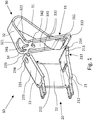
- FIG. 1 is an electrical terminal 10, comprising a metal part 20 and an attachable to the metal part 20 clamping spring 30 is shown.
- the metal part 20 has a contact leg 21 and a mounting leg 23 connected to the contact leg 21 via a web 22. Furthermore, it can be seen that the fastening leg 23 has a spring receiving portion 231 with an inner side 232, an outer side 233 and a spring receiving portion 231 arranged opening 234 and the contact leg 21 comprises a contact portion 211 with an inner side 212 and an outer side 213.
- the clamping spring 30 has a spring leg 31 with an end section 311, a back 32 connected to the spring leg 31 on the side remote from the end section 311, and a retaining leg 33 connected to the back 32.
- the back 32 includes a first recess 321 and the holding leg 33 includes a second recess 331, wherein the second recess 331 is formed such that the holding leg 33 comprises two side brackets 332 arranged parallel to each other, a lower support leg 333 and an upper transverse leg 34. Furthermore, it can be seen that the upper transverse web 34, the first recess 321 of the back 32 and the second recess 331 of the retaining leg 33 is separated from each other and at the upper transverse web 34, a first tongue 341 is formed.
- the clamping spring 30 can be plugged onto the metal part 20 such that the first tongue 341 engages from the inside 232 into the opening 234 of the spring receiving portion 231 and the end portion 311 of the spring leg 31 abuts against the inside 212 of the contact portion 21 and a spring force on the inside 212th of the contact portion 21 exerts.
- FIG. 2 is the plugged onto the metal part 20 clamping spring 30 is shown. It can be seen that in the attached state, the upper transverse web 34 abuts against the inner side 232 of the spring receiving portion 231. In this way, the spring force exerted by the spring leg 31 as a reaction force on the upper crossbar 34th introduced into the spring receiving portion 231 of the mounting leg 23.
- a portion of the contact portion 211 is angled downward and the lower abutment leg 333 abuts against the outer side 213 of the angled contact portion 211.
- the clamping spring 30 is fixed to the contact portion 211 such that a rotation of the clamping spring 30 can be reduced about the axis of the upper transverse web 34 or even completely prevented.
- a corresponding fixation on the spring receiving portion 231 may be formed.
- the first recess 321 is formed such that the back 32 has two webs 322 arranged parallel to one another.
- two recesses 235 are arranged, and in each case a web 322 engages in a recess 235 a.
- a fixation of the clamping spring 30 is indicated on the metal part 20 in the region of the spring receiving portion 231, which prevents rotation about the longitudinal axis of the first tongue 341.
- one of the first tongue 341 is also formed opposite second tongue 342.
- This second tongue 342 is used to prevent overloading of the clamping spring 30 when giving the spring leg 31 for contacting an electrical conductor end between the end portion 311 of the spring leg 31 and the inner side 212 of the contact portion 211.
- Both the clamping spring 30 and the metal part 20 are each a stamped and bent part. In this way, clamping spring 30 and metal part 20 can be produced with little effort. Due to the fact that the first tongue 341 and the second tongue 342 are formed on the upper transverse web 34 and the upper transverse web 34 separates the first recess 321 and the second recess 331 from each other, the first tongue 341 can during punching operation of the first recess 321 and second tongue 342 in the punching operation of the second recess 331 in length and width are formed independently.
Landscapes
- Connections Arranged To Contact A Plurality Of Conductors (AREA)
- Coupling Device And Connection With Printed Circuit (AREA)
- Connection Of Batteries Or Terminals (AREA)
Description
- Die Erfindung betrifft eine elektrische Anschlussklemme zur Aufnahme und elektrischen Kontaktierung eines elektrischen Leiters.
- Elektrische Anschlussklemmen zur Aufnahme und elektrischen Kontaktierung eines elektrischen Leiters sind aus der Praxis allgemein bekannt. Beispielsweise ist aus der
US 2010/0081346 A1 eine derartige Anschlussklemme bekannt. Derartige elektrische Anschlussklemmen weisen in der Regel ein Metallteil mit einem Halteabschnitt und einem Kontaktabschnitt und eine an dem Metallteil befestigte Federklemme mit einem abgewinkelten Befestigungsabschnitt auf. Zur Befestigung der Federklemme an dem Metallteil sind häufig an dem Halteabschnitt eine geprägte Rastnase und im Befestigungsabschnitt eine Aufnahmeöffnung angeordnet, in die die Rastnase eingreift. - Geprägte Rastnasen weisen in der Regel nur eine geringe Höhe auf und haben daher den Nachteil, dass die Befestigung der Federklemme auf dem Metallteil toleranzanfällig ist. Zudem sind durch die Abwinkelung des Befestigungsabschnitts bei der Herstellung der Federklemme zusätzliche Biegevorgänge erforderlich.
- Es ist daher die Aufgabe der Erfindung, eine elektrische Anschlussklemme anzugeben, die einfach herstellbar ist und eine toleranzunempfindliche Befestigungsvorrichtung aufweist.
- Diese Aufgabe wird durch den Gegenstand des Patentanspruchs 1 gelöst. Bevorzugte Weiterbildungen sind in den Unteransprüchen angegeben.
- Erfindungsgemäß ist somit eine elektrische Anschlussklemme vorgesehen, umfassend ein Metallteil und eine auf das Metallteil aufsteckbare Klemmfeder, wobei das Metallteil einen Kontaktschenkel und einen über einen Steg mit dem Kontaktschenkel verbundenen Befestigungsschenkel aufweist, der Befestigungsschenkel einen Federaufnahmeabschnitt mit einer Innenseite, einer Außenseite und einer im Federaufnahmeabschnitt angeordneten Öffnung aufweist und der Kontaktschenkel einen Kontaktabschnitt mit einer Innenseite und einer Außenseite umfasst, wobei die Klemmfeder einen Federschenkel mit einem Endabschnitt, einen auf der dem Endabschnitt abgewandten Seite mit dem Federschenkel verbundenen Rücken und einen mit dem Rücken verbundenen Halteschenkel aufweist, der Rücken eine erste Ausnehmung und der Halteschenkel eine zweite Ausnehmung aufweist, die zweite Ausnehmung derart ausgebildet ist, dass der Halteschenkel zwei parallel zueinander angeordnete Seitenbügel, einen unteren Anlageschenkel und einen oberen Quersteg umfasst, und der obere Quersteg die erste Ausnehmung des Rückens und die zweite Ausnehmung des Halteschenkels voneinander trennt, dadurch gekennzeichnet, dass am oberen Quersteg eine erste Zunge ausgebildet ist und die Klemmfeder derart auf das Metallteil aufsteckbar ist, dass die erste Zunge von der Innenseite in die Öffnung des Federaufnahmeabschnitts eingreift und der Endabschnitt des Federschenkels gegen die Innenseite des Kontaktabschnitts anliegt sowie eine Federkraft auf die Innenseite des Kontaktabschnitts ausübt.
- Es ist somit ein wesentlicher Aspekt der Erfindung, dass der Rücken eine erste Ausnehmung und der Halteschenkel eine zweite Ausnehmung aufweisen, die erste Ausnehmung und die zweite Ausnehmung durch den oberen Quersteg voneinander getrennt sind und am oberen Quersteg eine erste Zunge ausgebildet ist, wobei die erste Zunge zur Befestigung der Klemmfeder auf dem Metallteil von der Innenseite in die am Federaufnahmeabschnitt des Befestigungsschenkels angeordnete Öffnung eingreift und der Endabschnitt des Federschenkels gegen die Innenseite des Kontaktabschnitts anliegt.
- Eine weitere bevorzugte Weiterbildung der Erfindung sieht vor, dass der obere Quersteg gegen die Innenseite des Federaufnahmeabschnitts anliegt. Auf diese Weise wird die von dem Federschenkel ausgeübte Federkraft als Reaktionskraft über den oberen Quersteg in den Federaufnahmeabschnitt des Befestigungsschenkels eingeleitet.
- Die Länge der ersten Zunge kann unterschiedliche Maße aufweisen. Daher kann die Länge der ersten Zunge auch eine Länge aufweisen die größer als die Materialdicke des Befestigungsschenkels ist. Eine besonders bevorzugte Weiterbildung der Erfindung sieht jedoch vor, dass die Länge der ersten Zunge der Materialdicke des Befestigungsschenkels entspricht. Auf diese Weise wird eine Länge der ersten Zunge angegeben, die eine sichere Befestigung der Klemmfeder am Befestigungsschenkel bereitstellt.
- Weiterhin liegt eine bevorzugte Weiterbildung der Erfindung darin, dass ein Teilbereich des Kontaktabschnitts nach unten abgewinkelt ist und der untere Anlageschenkel gegen die Außenseite des abgewinkelten Kontaktabschnitts anliegt. Auf diese Weise wird die Klemmfeder am Kontaktabschnitt derart fixiert, dass eine Rotation der Klemmfeder um die Achse des oberen Querstegs reduziert werden kann.
- Gemäß einer weiteren bevorzugten Weiterbildung der Erfindung ist vorgesehen, dass der Randbereich des Kontaktabschnitts zwei Aussparungen aufweist, in die jeweils ein Seitenbügel eingreift. Auf diese Weise wird eine Fixierung der Klemmfeder auf dem Metallteil im Bereich des Kontaktabschnitts angegeben, die eine Rotation um die Längsachse der ersten Zunge unterbindet.
- Weiterhin sieht eine bevorzugte Weiterbildung der Erfindung vor, dass die erste Ausnehmung derart ausgebildet ist, dass der Rücken zwei parallel zueinander angeordnete Stege aufweist, der Federaufnahmeabschnitt des Befestigungsschenkels im Randbereich zwei Aussparungen aufweist und jeweils ein Steg in eine Aussparung eingreift. Auf dieses Weise wird eine Fixierung der Klemmfeder auf dem Metallteil im Bereich des Federaufnahmeabschnitts angegeben, die eine Rotation um die Längsachse der ersten Zunge unterbindet.
- Zur elektrischen Verbindung eines abisolierten Leiterendes mit der elektrischen Anschlussklemme wird das abisolierte Leiterende zwischen dem Endabschnitt des Federschenkels und der Innenseite des Kontaktabschnitts verklemmt. Zum Einführen des abisolierten Leiterendes in die elektrische Anschlussklemme wird der Federschenkel der Klemmfeder verschwenkt. Um eine Überlastung der Klemmfeder beim Verschwenken des Federschenkels vorzubeugen, sieht eine bevorzugte Weiterbildung der Erfindung vor, dass der obere Quersteg eine der ersten Zunge entgegen gerichtete zweite Zunge aufweist. Die zweite Zunge dient als Anschlag für den Federschenkel und reduziert den Schwenkwinkel des Federschenkels.
- Schließlich liegt eine weitere bevorzugte Weiterbildung der Erfindung darin, dass die Klemmfeder und das Metallteil Stanzbiegeteil sind. Auf diese Weise können Klemmfeder und Metallteil mit geringem Aufwand hergestellt werden. Bedingt dadurch, dass die erste Zunge und die zweite Zunge an dem oberen Quersteg ausgebildet sind und der obere Quersteg die erste Ausnehmung und die zweite Ausnehmung voneinander trennt, können die erste Zunge beim Stanzvorgang der ersten Ausnehmung und die zweite Zunge beim Stanzvorgang der zweiten Ausnehmung in Länge und Bereite unabhängig voneinander ausgebildet werden.
- Nachfolgend wird die Erfindung anhand eines bevorzugten Ausführungsbeispiels unter Bezugnahme auf die Zeichnung näher erläutert. In der Zeichnung zeigen:
- Fig. 1
- eine Explosionsdarstellung einer elektrischen Anschlussklemme gemäß einem bevorzugten Ausführungsbeispiel der Erfindung und
- Fig. 2
- eine dreidimensionale Ansicht der elektrischen Anschlussklemme gemäß dem bevorzugten Ausführungsbeispiel der Erfindung.
- In
Figur 1 ist eine elektrische Anschlussklemme 10, umfassend ein Metallteil 20 und eine auf das Metallteil 20 aufsteckbare Klemmfeder 30 gezeigt. - Das Metallteil 20 weist einen Kontaktschenkel 21 und einen über einen Steg 22 mit dem Kontaktschenkel 21 verbundenen Befestigungsschenkel 23 auf. Weiterhin ist ersichtlich, dass der Befestigungsschenkel 23 einen Federaufnahmeabschnitt 231 mit einer Innenseite 232, einer Außenseite 233 und einer im Federaufnahmeabschnitt 231 angeordneten Öffnung 234 aufweist und der Kontaktschenkel 21 einen Kontaktabschnitt 211 mit einer Innenseite 212 und einer Außenseite 213 umfasst.
- Die Klemmfeder 30 weist eine Federschenkel 31 mit einem Endabschnitt 311, einen auf der dem Endabschnitt 311 abgewandten Seite mit dem Federschenkel 31 verbundenen Rücken 32 und einen mit dem Rücken 32 verbundenen Halteschenkel 33 auf.
- Der Rücken 32 umfasst eine erste Ausnehmung 321 und der Halteschenkel 33 umfasst eine zweite Ausnehmung 331, wobei die zweite Ausnehmung 331 derart ausgebildet ist, dass der Halteschenkel 33 zwei parallel zueinander angeordnete Seitenbügel 332, einen unteren Anlageschenkel 333 und einen oberen Quersteg 34 umfasst. Weiterhin ist ersichtlich, dass der obere Quersteg 34 die erste Ausnehmung 321 des Rückens 32 und die zweite Ausnehmung 331 des Halteschenkels 33 voneinander trennt und am oberen Quersteg 34 eine erste Zunge 341 ausgebildet ist. Die Klemmfeder 30 ist derart auf das Metallteil 20 aufsteckbar, dass die erste Zunge 341 von der Innenseite 232 in die Öffnung 234 des Federaufnahmeabschnitts 231 eingreift und der Endabschnitt 311 des Federschenkels 31 gegen die Innenseite 212 des Kontaktabschnitts 21 anliegt sowie eine Federkraft auf die Innenseite 212 des Kontaktabschnitts 21 ausübt.
- In
Figur 2 ist die auf das Metallteil 20 aufgesteckte Klemmfeder 30 gezeigt. Es ist ersichtlich, dass im aufgesteckten Zustand der obere Quersteg 34 gegen die Innenseite 232 des Federaufnahmeabschnitts 231 anliegt. Auf diese Weise wird die von dem Federschenkel 31 ausgeübte Federkraft als Reaktionskraft über den oberen Quersteg 34 in den Federaufnahmeabschnitt 231 des Befestigungsschenkels 23 eingeleitet. - Weiterhin ist ersichtlich, dass ein Teilbereich des Kontaktabschnitts 211 nach unten abgewinkelt ist und der untere Anlageschenkel 333 gegen die Außenseite 213 des abgewinkelten Kontaktabschnitts 211 anliegt. Auf diese Weise wird die Klemmfeder 30 am Kontaktabschnitt 211 derart fixiert, dass eine Rotation der Klemmfeder 30 um die Achse des oberen Querstegs 34 reduziert oder sogar vollständig unterbunden werden kann.
- Im Randbereich des Kontaktabschnitts 211 sind zwei Aussparungen 214 angeordnet, in die jeweils ein Seitenbügel 332 eingreift. Auf diese Weise wird eine Fixierung der Klemmfeder 30 auf dem Metallteil 20 im Bereich des Kontaktabschnitts 211 erzielt, die eine Rotation um die Längsachse der ersten Zunge 341 unterbindet.
- Alternativ oder in Ergänzung zur Fixierung der Klemmfeder 30 im Bereich des Kontaktabschnitts 211, um eine Rotation der Klemmfeder 30 um die Längsachse der ersten Zunge 341 zu vermeiden, kann eine entsprechende Fixierung am Federaufnahmeabschnitt 231 ausgebildet sein. Hierzu ist die erste Ausnehmung 321 derart ausgebildet, dass der Rücken 32 zwei parallel zueinander angeordnete Stege 322 aufweist. Am Federaufnahmeabschnitt 231 des Befestigungsschenkels 23 im Randbereich sind zwei Aussparungen 235 angeordnet, und jeweils ein Steg 322 greift in eine Aussparung 235 ein. Auf dieses Weise wird eine Fixierung der Klemmfeder 30 auf dem Metallteil 20 im Bereich des Federaufnahmeabschnitts 231 angegeben, die eine Rotation um die Längsachse der ersten Zunge 341 unterbindet.
- Am oberen Quersteg 34 ist zudem eine der ersten Zunge 341 entgegen gerichtete zweite Zunge 342 ausgebildet. Diese zweite Zunge 342 dient der Vorbeugung einer Überlastung der Klemmfeder 30 beim Verschenken des Federschenkels 31 zur Kontaktierung eines elektrischen Leiterendes zwischen dem Endabschnitt 311 des Federschenkels 31 und der Innenseite 212 des Kontaktabschnitts 211.
- Sowohl die Klemmfeder 30 als auch das das Metallteil 20 sind jeweils ein Stanzbiegeteil. Auf diese Weise können Klemmfeder 30 und Metallteil 20 mit geringem Aufwand hergestellt werden. Bedingt dadurch, dass die erste Zunge 341 und die zweite Zunge 342 an dem oberen Quersteg 34 ausgebildet sind und der obere Quersteg 34 die erste Ausnehmung 321 und die zweite Ausnehmung 331 voneinander trennt, können die erste Zunge 341 beim Stanzvorgang der ersten Ausnehmung 321 und die zweite Zunge 342 beim Stanzvorgang der zweiten Ausnehmung 331 in Länge und Bereite unabhängig voneinander ausgebildet werden.
-
- 10
- Elektrische Anschlussklemme
- 20
- Metallteil
- 21
- Kontaktschenkel
- 211
- Kontaktabschnitt
- 212
- Innenseite
- 213
- Außenseite
- 214
- Aussparung
- 22
- Steg
- 23
- Befestigungsschenkel
- 231
- Federaufnahmeabschnitt
- 232
- Innenseite
- 233
- Außenseite
- 234
- Öffnung
- 235
- Aussparungen
- 30
- Klemmfeder
- 31
- Federschenkel
- 311
- Endabschnitt
- 32
- Rücken
- 321
- Erste Ausnehmung
- 322
- Stege
- 33
- Halteschenkel
- 331
- Zweite Ausnehmung
- 332
- Seitenbügel
- 333
- Anlageschenkel
- 34
- Quersteg
- 341
- Erste Zunge
Claims (8)
- Elektrische Anschlussklemme, umfassend ein Metallteil (20) und eine auf das Metallteil (20) aufsteckbare Klemmfeder (30), wobei
das Metallteil (20) einen Kontaktschenkel (21) und einen über einen Steg (22) mit dem Kontaktschenkel (21) verbundenen Befestigungsschenkel (23) aufweist,
der Befestigungsschenkel (23) einen Federaufnahmeabschnitt (231) mit einer Innenseite (232), einer Außenseite (233) und einer im Federaufnahmeabschnitt (231) angeordneten Öffnung (234) aufweist und
der Kontaktschenkel (21) einen Kontaktabschnitt (211) mit einer Innenseite (212) und einer Außenseite (213) umfasst, wobei
die Klemmfeder (30) einen Federschenkel (31) mit einem Endabschnitt (311), einen auf der dem Endabschnitt (311) abgewandten Seite mit dem Federschenkel (31) verbundenen Rücken (32) und einen mit dem Rücken (32) verbundenen Halteschenkel (33) aufweist,
der Rücken (32) eine erste Ausnehmung (321) und der Halteschenkel (33) eine zweite Ausnehmung (331) aufweist,
die zweite Ausnehmung (331) derart ausgebildet ist, dass der Halteschenkel (33) zwei parallel zueinander angeordnete Seitenbügel (332), einen unteren Anlageschenkel (333) und einen oberen Quersteg (34) umfasst, und
der obere Quersteg (34) die erste Ausnehmung (321) des Rückens (32) und die zweite Ausnehmung (331) des Halteschenkels (33) voneinander trennt,
dadurch gekennzeichnet, dass am oberen Quersteg (34) eine erste Zunge (341) ausgebildet ist und die Klemmfeder (30) derart auf das Metallteil (20) aufsteckbar ist, dass die erste Zunge (341) von der Innenseite (232) in die Öffnung (234) des Federaufnahmeabschnitts (231) eingreift und der Endabschnitt (311) des Federschenkels (31) gegen die Innenseite (212) des Kontaktabschnitts (211) anliegt sowie eine Federkraft auf die Innenseite (212) des Kontaktabschnitts (211) ausübt. - Elektrische Anschlussklemme nach Anspruch 1, dadurch gekennzeichnet, dass der obere Quersteg (34) gegen die Innenseite (232) des Federaufnahmeabschnitts (231) anliegt.
- Elektrische Anschlussklemme nach Anspruch 1 oder 2, dadurch gekennzeichnet, dass die Länge der ersten Zunge (341) der Materialdicke des Befestigungsschenkels (23) entspricht.
- Elektrische Anschlussklemme nach einem der Ansprüche 1 bis 3, dadurch gekennzeichnet, dass ein Teilbereich des Kontaktabschnitts (211) nach unten abgewinkelt ist und der untere Anlageschenkel (333) gegen die Außenseite (213) des abgewinkelten Kontaktabschnitts (211) anliegt.
- Elektrische Anschlussklemme nach einem der Ansprüche 1 bis 4, dadurch gekennzeichnet, dass der Randbereich des Kontaktabschnitts (211) zwei Aussparungen (214) aufweist, in die jeweils ein Seitenbügel (332) eingreift.
- Elektrische Anschlussklemme nach einem der Ansprüche 1 bis 5, dadurch gekennzeichnet, dass die erste Ausnehmung (321) derart ausgebildet ist, dass der Rücken (32) zwei parallel zueinander angeordnete Stege (322) aufweist und der Federaufnahmeabschnitt (231) des Befestigungsschenkels (23) im Randbereich zwei Aussparungen (235) aufweist, und jeweils ein Steg (322) in eine Aussparung (235) eingreift.
- Elektrische Anschlussklemme nach einem der Ansprüche 1 bis 6, dadurch gekennzeichnet, dass der obere Quersteg (34) eine der ersten Zunge (341) entgegen gerichtete zweite Zunge (342) aufweist.
- Elektrische Anschlussklemme nach einem der Ansprüche 1 bis 7, dadurch gekennzeichnet, dass die Klemmfeder (30) und das Metallteil (20) jeweils ein Stanzbiegeteil ist.
Applications Claiming Priority (2)
| Application Number | Priority Date | Filing Date | Title |
|---|---|---|---|
| DE102014103638.7A DE102014103638B4 (de) | 2014-03-17 | 2014-03-17 | Elektrische Anschlussklemme |
| PCT/EP2015/055524 WO2015140148A1 (de) | 2014-03-17 | 2015-03-17 | Elektrische anschlussklemme |
Publications (2)
| Publication Number | Publication Date |
|---|---|
| EP3120421A1 EP3120421A1 (de) | 2017-01-25 |
| EP3120421B1 true EP3120421B1 (de) | 2018-04-18 |
Family
ID=52686364
Family Applications (1)
| Application Number | Title | Priority Date | Filing Date |
|---|---|---|---|
| EP15710490.2A Active EP3120421B1 (de) | 2014-03-17 | 2015-03-17 | Elektrische anschlussklemme |
Country Status (5)
| Country | Link |
|---|---|
| US (1) | US9831568B2 (de) |
| EP (1) | EP3120421B1 (de) |
| CN (1) | CN106104928B (de) |
| DE (1) | DE102014103638B4 (de) |
| WO (1) | WO2015140148A1 (de) |
Families Citing this family (9)
| Publication number | Priority date | Publication date | Assignee | Title |
|---|---|---|---|---|
| DE102016208291B4 (de) * | 2016-05-13 | 2023-09-07 | Zf Friedrichshafen Ag | Federklammer, Montagewerkzeug sowie Verfahren zum Fixieren von Kontaktpartnern und Verbindungssystem zum Herstellen einer elektrischen und mechanischen Verbindung zwischen Kontaktpartnern |
| DE102016111536A1 (de) * | 2016-06-23 | 2017-12-28 | Wago Verwaltungsgesellschaft Mbh | Kontakteinsatz einer Federkraftanschlussklemme sowie damit ausgebildete Federkraftanschlussklemme |
| DE102016111627A1 (de) | 2016-06-24 | 2017-12-28 | Wago Verwaltungsgesellschaft Mbh | Leiteranschlussklemme |
| US9705212B1 (en) | 2016-10-05 | 2017-07-11 | Dinkle Enterprise Co., Ltd. | Structure improvement for connection terminals of terminal block |
| EP3306750A1 (de) * | 2016-10-06 | 2018-04-11 | Dinkle Enterprise Co., Ltd. | Strukturverbesserung für anschlussklemmen einer anschlussleiste |
| DE102016122238A1 (de) * | 2016-11-18 | 2018-05-24 | Wago Verwaltungsgesellschaft Mbh | Federklemmkontakt zur Kontaktierung elektrischer Leiter, Leiteranschlussklemme und Verfahren zur Herstellung eines Federklemmkontakts |
| TWD184275S (zh) * | 2016-12-13 | 2017-07-11 | 百容電子股份有限公司 | 連接器端子的部分 |
| US11808116B2 (en) | 2020-06-23 | 2023-11-07 | Halliburton Energy Services, Inc. | Connector for perforating gun system |
| CN113972506B (zh) * | 2020-07-24 | 2022-12-16 | 菲尼克斯亚太电气(南京)有限公司 | 一种带有操作声音反馈的接线端子 |
Family Cites Families (15)
| Publication number | Priority date | Publication date | Assignee | Title |
|---|---|---|---|---|
| TW395069B (en) * | 1995-08-23 | 2000-06-21 | Connector Systems Tech Nv | Connector |
| DE102004046471B3 (de) | 2004-09-23 | 2006-02-09 | Phoenix Contact Gmbh & Co. Kg | Elektrische Anschluß- oder Verbindungsklemme |
| DE102007024661A1 (de) * | 2006-05-26 | 2007-11-29 | Phoenix Contact Gmbh & Co. Kg | Elektrische Anschlussklemme mit einem Klemmengehäuse |
| DE102006057712B3 (de) * | 2006-12-07 | 2008-04-10 | Phoenix Contact Gmbh & Co. Kg | Federkraftklemme zum Anschluß von Leiterenden und Kabelschuhen |
| RU2422957C2 (ru) * | 2007-01-31 | 2011-06-27 | Мульти-Холдинг Аг | Контактный элемент и применение этого элемента в разъемном соединении |
| DE102007024690B4 (de) * | 2007-05-25 | 2009-06-04 | Phoenix Contact Gmbh & Co. Kg | Elektrische Anschluß- oder Verbindungsklemme |
| DE102008025433B4 (de) * | 2008-02-29 | 2011-01-13 | Phoenix Contact Gmbh & Co. Kg | Klemmenanschlußblock |
| DE102008039219B4 (de) * | 2008-08-22 | 2014-08-07 | Phoenix Contact Gmbh & Co. Kg | Elektrische Anschlussvorrichtung |
| DE202009016064U1 (de) * | 2009-11-26 | 2011-04-14 | Phoenix Contact Gmbh & Co. Kg | Kontaktelementanordnung sowie Anschlussvorrichtung für eine derartige Kontaktelementanordnung |
| DE102010025930B4 (de) * | 2010-07-02 | 2019-10-17 | Phoenix Contact Gmbh & Co. Kg | Anschlussklemme |
| ES2473892T3 (es) * | 2010-10-12 | 2014-07-08 | Bals Elektrotechnik Gmbh & Co. Kg | Borne de conexión sin tornillo |
| DE102011011080B4 (de) * | 2011-02-11 | 2013-04-11 | Wago Verwaltungsgesellschaft Mbh | Federklemmanschluss und Leiteranschlusseinheit |
| DE102011051536A1 (de) * | 2011-07-04 | 2013-01-10 | Phoenix Contact Gmbh & Co. Kg | Klemmeinheit einer elektrischen Anschlussklemme |
| CN202259804U (zh) * | 2011-09-22 | 2012-05-30 | 菲尼克斯亚太电气(南京)有限公司 | 一种蝶形弹簧连接器 |
| DE202013100635U1 (de) * | 2013-02-13 | 2013-03-04 | Wago Verwaltungsgesellschaft Mbh | Federklemmkontakt und Verbindungsklemme für elektrische Leiter |
-
2014
- 2014-03-17 DE DE102014103638.7A patent/DE102014103638B4/de not_active Expired - Fee Related
-
2015
- 2015-03-17 CN CN201580014572.8A patent/CN106104928B/zh active Active
- 2015-03-17 WO PCT/EP2015/055524 patent/WO2015140148A1/de active Application Filing
- 2015-03-17 US US15/122,641 patent/US9831568B2/en active Active
- 2015-03-17 EP EP15710490.2A patent/EP3120421B1/de active Active
Non-Patent Citations (1)
| Title |
|---|
| None * |
Also Published As
| Publication number | Publication date |
|---|---|
| US9831568B2 (en) | 2017-11-28 |
| CN106104928B (zh) | 2018-08-28 |
| US20170069978A1 (en) | 2017-03-09 |
| DE102014103638B4 (de) | 2016-05-19 |
| DE102014103638A1 (de) | 2015-09-17 |
| CN106104928A (zh) | 2016-11-09 |
| EP3120421A1 (de) | 2017-01-25 |
| WO2015140148A1 (de) | 2015-09-24 |
Similar Documents
| Publication | Publication Date | Title |
|---|---|---|
| EP3120421B1 (de) | Elektrische anschlussklemme | |
| EP2162952B1 (de) | Elektrische anschluss- oder verbindungsklemme | |
| DE102011055919B4 (de) | Anschlussklemme | |
| EP3058624B1 (de) | Steckverbinder mit verrastungssystem | |
| EP2131449A1 (de) | Einzelklemme | |
| EP1085618B1 (de) | Steckverbindungssystem | |
| EP3586404B1 (de) | Federkraftanschluss und rundsteckverbinder mit einer vielzahl von federkraftanschlüssen | |
| EP1691454B1 (de) | Elektrischer Steckverbinder mit Verriegelungsklammern | |
| BE1025389A1 (de) | ANSCHLUSSEINRICHTUNG ZUM ANSCHLIEßEN EINER ELEKTRISCHEN LEITUNG | |
| DE102014117062B4 (de) | Federkraftklemme | |
| WO2011082748A1 (de) | Elektrische anschlussklemme | |
| DE102016112831A1 (de) | Anschlussklemme | |
| AT13943U1 (de) | Anschluss- oder Verbindungsklemme | |
| EP1394902A1 (de) | Anschlussklemme | |
| DE202008016856U1 (de) | Elektrische Anschluss- oder Verbindungsklemme | |
| DE202005005548U1 (de) | Mit einer bügelförmigen Drahtschutzfeder versehenes elektrisches Kontaktelement | |
| DE3408115C2 (de) | Verriegelbare und abdrückbare mehrpolige elektrische Steckverbindung in Rechteckform | |
| EP3026350B1 (de) | Dunstabzugshaube mit einer baueinheit | |
| DE102015120002B4 (de) | Verbindungsvorrichtung und Verbindungsverfahren | |
| DE102008015374B4 (de) | Elektrische Klemme | |
| WO2012116970A1 (de) | Federkäfig | |
| DE202009016064U1 (de) | Kontaktelementanordnung sowie Anschlussvorrichtung für eine derartige Kontaktelementanordnung | |
| EP2009745B1 (de) | Elektrisches Gerät mit einer Federklemmeinheit | |
| DE102010039454A1 (de) | Verschluss einer Befestigungsvorrichtung für ein Flächenelement einer Dunstabzugshaube und Dunstabzugshaube | |
| DE102018107886B4 (de) | Steckverbindersystem mit einem bistabilen Element |
Legal Events
| Date | Code | Title | Description |
|---|---|---|---|
| STAA | Information on the status of an ep patent application or granted ep patent |
Free format text: STATUS: THE INTERNATIONAL PUBLICATION HAS BEEN MADE |
|
| PUAI | Public reference made under article 153(3) epc to a published international application that has entered the european phase |
Free format text: ORIGINAL CODE: 0009012 |
|
| STAA | Information on the status of an ep patent application or granted ep patent |
Free format text: STATUS: REQUEST FOR EXAMINATION WAS MADE |
|
| 17P | Request for examination filed |
Effective date: 20160902 |
|
| AK | Designated contracting states |
Kind code of ref document: A1 Designated state(s): AL AT BE BG CH CY CZ DE DK EE ES FI FR GB GR HR HU IE IS IT LI LT LU LV MC MK MT NL NO PL PT RO RS SE SI SK SM TR |
|
| AX | Request for extension of the european patent |
Extension state: BA ME |
|
| DAV | Request for validation of the european patent (deleted) | ||
| DAX | Request for extension of the european patent (deleted) | ||
| GRAP | Despatch of communication of intention to grant a patent |
Free format text: ORIGINAL CODE: EPIDOSNIGR1 |
|
| STAA | Information on the status of an ep patent application or granted ep patent |
Free format text: STATUS: GRANT OF PATENT IS INTENDED |
|
| INTG | Intention to grant announced |
Effective date: 20170830 |
|
| GRAS | Grant fee paid |
Free format text: ORIGINAL CODE: EPIDOSNIGR3 |
|
| GRAL | Information related to payment of fee for publishing/printing deleted |
Free format text: ORIGINAL CODE: EPIDOSDIGR3 |
|
| GRAS | Grant fee paid |
Free format text: ORIGINAL CODE: EPIDOSNIGR3 |
|
| GRAA | (expected) grant |
Free format text: ORIGINAL CODE: 0009210 |
|
| STAA | Information on the status of an ep patent application or granted ep patent |
Free format text: STATUS: THE PATENT HAS BEEN GRANTED |
|
| AK | Designated contracting states |
Kind code of ref document: B1 Designated state(s): AL AT BE BG CH CY CZ DE DK EE ES FI FR GB GR HR HU IE IS IT LI LT LU LV MC MK MT NL NO PL PT RO RS SE SI SK SM TR |
|
| REG | Reference to a national code |
Ref country code: GB Ref legal event code: FG4D Free format text: NOT ENGLISH |
|
| REG | Reference to a national code |
Ref country code: CH Ref legal event code: EP |
|
| REG | Reference to a national code |
Ref country code: AT Ref legal event code: REF Ref document number: 991407 Country of ref document: AT Kind code of ref document: T Effective date: 20180515 |
|
| REG | Reference to a national code |
Ref country code: IE Ref legal event code: FG4D Free format text: LANGUAGE OF EP DOCUMENT: GERMAN |
|
| REG | Reference to a national code |
Ref country code: DE Ref legal event code: R096 Ref document number: 502015003929 Country of ref document: DE |
|
| REG | Reference to a national code |
Ref country code: NL Ref legal event code: MP Effective date: 20180418 |
|
| REG | Reference to a national code |
Ref country code: LT Ref legal event code: MG4D |
|
| PG25 | Lapsed in a contracting state [announced via postgrant information from national office to epo] |
Ref country code: NL Free format text: LAPSE BECAUSE OF FAILURE TO SUBMIT A TRANSLATION OF THE DESCRIPTION OR TO PAY THE FEE WITHIN THE PRESCRIBED TIME-LIMIT Effective date: 20180418 |
|
| PG25 | Lapsed in a contracting state [announced via postgrant information from national office to epo] |
Ref country code: FI Free format text: LAPSE BECAUSE OF FAILURE TO SUBMIT A TRANSLATION OF THE DESCRIPTION OR TO PAY THE FEE WITHIN THE PRESCRIBED TIME-LIMIT Effective date: 20180418 Ref country code: PL Free format text: LAPSE BECAUSE OF FAILURE TO SUBMIT A TRANSLATION OF THE DESCRIPTION OR TO PAY THE FEE WITHIN THE PRESCRIBED TIME-LIMIT Effective date: 20180418 Ref country code: LT Free format text: LAPSE BECAUSE OF FAILURE TO SUBMIT A TRANSLATION OF THE DESCRIPTION OR TO PAY THE FEE WITHIN THE PRESCRIBED TIME-LIMIT Effective date: 20180418 Ref country code: BG Free format text: LAPSE BECAUSE OF FAILURE TO SUBMIT A TRANSLATION OF THE DESCRIPTION OR TO PAY THE FEE WITHIN THE PRESCRIBED TIME-LIMIT Effective date: 20180718 Ref country code: SE Free format text: LAPSE BECAUSE OF FAILURE TO SUBMIT A TRANSLATION OF THE DESCRIPTION OR TO PAY THE FEE WITHIN THE PRESCRIBED TIME-LIMIT Effective date: 20180418 Ref country code: NO Free format text: LAPSE BECAUSE OF FAILURE TO SUBMIT A TRANSLATION OF THE DESCRIPTION OR TO PAY THE FEE WITHIN THE PRESCRIBED TIME-LIMIT Effective date: 20180718 Ref country code: AL Free format text: LAPSE BECAUSE OF FAILURE TO SUBMIT A TRANSLATION OF THE DESCRIPTION OR TO PAY THE FEE WITHIN THE PRESCRIBED TIME-LIMIT Effective date: 20180418 Ref country code: ES Free format text: LAPSE BECAUSE OF FAILURE TO SUBMIT A TRANSLATION OF THE DESCRIPTION OR TO PAY THE FEE WITHIN THE PRESCRIBED TIME-LIMIT Effective date: 20180418 |
|
| PG25 | Lapsed in a contracting state [announced via postgrant information from national office to epo] |
Ref country code: GR Free format text: LAPSE BECAUSE OF FAILURE TO SUBMIT A TRANSLATION OF THE DESCRIPTION OR TO PAY THE FEE WITHIN THE PRESCRIBED TIME-LIMIT Effective date: 20180719 Ref country code: RS Free format text: LAPSE BECAUSE OF FAILURE TO SUBMIT A TRANSLATION OF THE DESCRIPTION OR TO PAY THE FEE WITHIN THE PRESCRIBED TIME-LIMIT Effective date: 20180418 Ref country code: HR Free format text: LAPSE BECAUSE OF FAILURE TO SUBMIT A TRANSLATION OF THE DESCRIPTION OR TO PAY THE FEE WITHIN THE PRESCRIBED TIME-LIMIT Effective date: 20180418 Ref country code: LV Free format text: LAPSE BECAUSE OF FAILURE TO SUBMIT A TRANSLATION OF THE DESCRIPTION OR TO PAY THE FEE WITHIN THE PRESCRIBED TIME-LIMIT Effective date: 20180418 |
|
| PG25 | Lapsed in a contracting state [announced via postgrant information from national office to epo] |
Ref country code: PT Free format text: LAPSE BECAUSE OF FAILURE TO SUBMIT A TRANSLATION OF THE DESCRIPTION OR TO PAY THE FEE WITHIN THE PRESCRIBED TIME-LIMIT Effective date: 20180820 |
|
| REG | Reference to a national code |
Ref country code: DE Ref legal event code: R097 Ref document number: 502015003929 Country of ref document: DE |
|
| PG25 | Lapsed in a contracting state [announced via postgrant information from national office to epo] |
Ref country code: DK Free format text: LAPSE BECAUSE OF FAILURE TO SUBMIT A TRANSLATION OF THE DESCRIPTION OR TO PAY THE FEE WITHIN THE PRESCRIBED TIME-LIMIT Effective date: 20180418 Ref country code: EE Free format text: LAPSE BECAUSE OF FAILURE TO SUBMIT A TRANSLATION OF THE DESCRIPTION OR TO PAY THE FEE WITHIN THE PRESCRIBED TIME-LIMIT Effective date: 20180418 Ref country code: SK Free format text: LAPSE BECAUSE OF FAILURE TO SUBMIT A TRANSLATION OF THE DESCRIPTION OR TO PAY THE FEE WITHIN THE PRESCRIBED TIME-LIMIT Effective date: 20180418 Ref country code: CZ Free format text: LAPSE BECAUSE OF FAILURE TO SUBMIT A TRANSLATION OF THE DESCRIPTION OR TO PAY THE FEE WITHIN THE PRESCRIBED TIME-LIMIT Effective date: 20180418 Ref country code: RO Free format text: LAPSE BECAUSE OF FAILURE TO SUBMIT A TRANSLATION OF THE DESCRIPTION OR TO PAY THE FEE WITHIN THE PRESCRIBED TIME-LIMIT Effective date: 20180418 |
|
| PLBE | No opposition filed within time limit |
Free format text: ORIGINAL CODE: 0009261 |
|
| STAA | Information on the status of an ep patent application or granted ep patent |
Free format text: STATUS: NO OPPOSITION FILED WITHIN TIME LIMIT |
|
| PG25 | Lapsed in a contracting state [announced via postgrant information from national office to epo] |
Ref country code: SM Free format text: LAPSE BECAUSE OF FAILURE TO SUBMIT A TRANSLATION OF THE DESCRIPTION OR TO PAY THE FEE WITHIN THE PRESCRIBED TIME-LIMIT Effective date: 20180418 |
|
| 26N | No opposition filed |
Effective date: 20190121 |
|
| PG25 | Lapsed in a contracting state [announced via postgrant information from national office to epo] |
Ref country code: SI Free format text: LAPSE BECAUSE OF FAILURE TO SUBMIT A TRANSLATION OF THE DESCRIPTION OR TO PAY THE FEE WITHIN THE PRESCRIBED TIME-LIMIT Effective date: 20180418 |
|
| PG25 | Lapsed in a contracting state [announced via postgrant information from national office to epo] |
Ref country code: MC Free format text: LAPSE BECAUSE OF FAILURE TO SUBMIT A TRANSLATION OF THE DESCRIPTION OR TO PAY THE FEE WITHIN THE PRESCRIBED TIME-LIMIT Effective date: 20180418 |
|
| REG | Reference to a national code |
Ref country code: CH Ref legal event code: PL |
|
| GBPC | Gb: european patent ceased through non-payment of renewal fee |
Effective date: 20190317 |
|
| PG25 | Lapsed in a contracting state [announced via postgrant information from national office to epo] |
Ref country code: LU Free format text: LAPSE BECAUSE OF NON-PAYMENT OF DUE FEES Effective date: 20190317 |
|
| REG | Reference to a national code |
Ref country code: BE Ref legal event code: MM Effective date: 20190331 |
|
| PG25 | Lapsed in a contracting state [announced via postgrant information from national office to epo] |
Ref country code: GB Free format text: LAPSE BECAUSE OF NON-PAYMENT OF DUE FEES Effective date: 20190317 Ref country code: CH Free format text: LAPSE BECAUSE OF NON-PAYMENT OF DUE FEES Effective date: 20190331 Ref country code: IE Free format text: LAPSE BECAUSE OF NON-PAYMENT OF DUE FEES Effective date: 20190317 Ref country code: LI Free format text: LAPSE BECAUSE OF NON-PAYMENT OF DUE FEES Effective date: 20190331 |
|
| PG25 | Lapsed in a contracting state [announced via postgrant information from national office to epo] |
Ref country code: BE Free format text: LAPSE BECAUSE OF NON-PAYMENT OF DUE FEES Effective date: 20190331 |
|
| PG25 | Lapsed in a contracting state [announced via postgrant information from national office to epo] |
Ref country code: TR Free format text: LAPSE BECAUSE OF FAILURE TO SUBMIT A TRANSLATION OF THE DESCRIPTION OR TO PAY THE FEE WITHIN THE PRESCRIBED TIME-LIMIT Effective date: 20180418 |
|
| PG25 | Lapsed in a contracting state [announced via postgrant information from national office to epo] |
Ref country code: MT Free format text: LAPSE BECAUSE OF FAILURE TO SUBMIT A TRANSLATION OF THE DESCRIPTION OR TO PAY THE FEE WITHIN THE PRESCRIBED TIME-LIMIT Effective date: 20180418 |
|
| REG | Reference to a national code |
Ref country code: AT Ref legal event code: MM01 Ref document number: 991407 Country of ref document: AT Kind code of ref document: T Effective date: 20200317 |
|
| PG25 | Lapsed in a contracting state [announced via postgrant information from national office to epo] |
Ref country code: CY Free format text: LAPSE BECAUSE OF FAILURE TO SUBMIT A TRANSLATION OF THE DESCRIPTION OR TO PAY THE FEE WITHIN THE PRESCRIBED TIME-LIMIT Effective date: 20180418 |
|
| PG25 | Lapsed in a contracting state [announced via postgrant information from national office to epo] |
Ref country code: IS Free format text: LAPSE BECAUSE OF FAILURE TO SUBMIT A TRANSLATION OF THE DESCRIPTION OR TO PAY THE FEE WITHIN THE PRESCRIBED TIME-LIMIT Effective date: 20180818 |
|
| PG25 | Lapsed in a contracting state [announced via postgrant information from national office to epo] |
Ref country code: HU Free format text: LAPSE BECAUSE OF FAILURE TO SUBMIT A TRANSLATION OF THE DESCRIPTION OR TO PAY THE FEE WITHIN THE PRESCRIBED TIME-LIMIT; INVALID AB INITIO Effective date: 20150317 |
|
| PG25 | Lapsed in a contracting state [announced via postgrant information from national office to epo] |
Ref country code: AT Free format text: LAPSE BECAUSE OF NON-PAYMENT OF DUE FEES Effective date: 20200317 |
|
| PG25 | Lapsed in a contracting state [announced via postgrant information from national office to epo] |
Ref country code: MK Free format text: LAPSE BECAUSE OF FAILURE TO SUBMIT A TRANSLATION OF THE DESCRIPTION OR TO PAY THE FEE WITHIN THE PRESCRIBED TIME-LIMIT Effective date: 20180418 |
|
| PGFP | Annual fee paid to national office [announced via postgrant information from national office to epo] |
Ref country code: FR Payment date: 20230323 Year of fee payment: 9 |
|
| PGFP | Annual fee paid to national office [announced via postgrant information from national office to epo] |
Ref country code: IT Payment date: 20230321 Year of fee payment: 9 |
|
| P01 | Opt-out of the competence of the unified patent court (upc) registered |
Effective date: 20230424 |
|
| PGFP | Annual fee paid to national office [announced via postgrant information from national office to epo] |
Ref country code: DE Payment date: 20230530 Year of fee payment: 9 |