EP3117809B1 - Einwegwindel vom hosentyp und herstellungsverfahren dafür - Google Patents
Einwegwindel vom hosentyp und herstellungsverfahren dafür Download PDFInfo
- Publication number
- EP3117809B1 EP3117809B1 EP15761058.5A EP15761058A EP3117809B1 EP 3117809 B1 EP3117809 B1 EP 3117809B1 EP 15761058 A EP15761058 A EP 15761058A EP 3117809 B1 EP3117809 B1 EP 3117809B1
- Authority
- EP
- European Patent Office
- Prior art keywords
- elastic belt
- folded part
- underpants
- folded
- disposable diaper
- Prior art date
- Legal status (The legal status is an assumption and is not a legal conclusion. Google has not performed a legal analysis and makes no representation as to the accuracy of the status listed.)
- Active
Links
- 238000004519 manufacturing process Methods 0.000 title claims description 44
- 239000000463 material Substances 0.000 claims description 50
- 238000005304 joining Methods 0.000 claims description 40
- 238000005520 cutting process Methods 0.000 claims description 26
- 238000003466 welding Methods 0.000 claims description 16
- 230000001965 increasing effect Effects 0.000 claims description 14
- 238000000034 method Methods 0.000 claims description 13
- 230000015572 biosynthetic process Effects 0.000 claims description 9
- 210000002414 leg Anatomy 0.000 description 61
- 239000000835 fiber Substances 0.000 description 34
- 239000006096 absorbing agent Substances 0.000 description 33
- 239000002250 absorbent Substances 0.000 description 32
- 230000000694 effects Effects 0.000 description 26
- 239000007788 liquid Substances 0.000 description 26
- 239000004745 nonwoven fabric Substances 0.000 description 23
- 229920000642 polymer Polymers 0.000 description 23
- 239000000853 adhesive Substances 0.000 description 22
- 230000001070 adhesive effect Effects 0.000 description 22
- 239000002245 particle Substances 0.000 description 21
- 239000004831 Hot glue Substances 0.000 description 19
- 210000001217 buttock Anatomy 0.000 description 14
- 230000002745 absorbent Effects 0.000 description 13
- 238000010521 absorption reaction Methods 0.000 description 13
- 238000012360 testing method Methods 0.000 description 12
- -1 polyethylene Polymers 0.000 description 11
- XLYOFNOQVPJJNP-UHFFFAOYSA-N water Substances O XLYOFNOQVPJJNP-UHFFFAOYSA-N 0.000 description 11
- 239000011229 interlayer Substances 0.000 description 9
- 239000004743 Polypropylene Substances 0.000 description 8
- 229920001155 polypropylene Polymers 0.000 description 8
- 238000007789 sealing Methods 0.000 description 8
- 229920001971 elastomer Polymers 0.000 description 7
- 239000002985 plastic film Substances 0.000 description 7
- 239000005060 rubber Substances 0.000 description 7
- 238000010586 diagram Methods 0.000 description 6
- 230000029142 excretion Effects 0.000 description 6
- 210000004013 groin Anatomy 0.000 description 6
- 229920006255 plastic film Polymers 0.000 description 6
- 239000000047 product Substances 0.000 description 6
- 238000004080 punching Methods 0.000 description 6
- 239000004698 Polyethylene Substances 0.000 description 5
- 239000002131 composite material Substances 0.000 description 5
- 229920000573 polyethylene Polymers 0.000 description 5
- 229920002994 synthetic fiber Polymers 0.000 description 5
- 239000012209 synthetic fiber Substances 0.000 description 5
- 244000043261 Hevea brasiliensis Species 0.000 description 4
- 229920003052 natural elastomer Polymers 0.000 description 4
- 229920001194 natural rubber Polymers 0.000 description 4
- 238000003672 processing method Methods 0.000 description 4
- 229920003051 synthetic elastomer Polymers 0.000 description 4
- 239000005061 synthetic rubber Substances 0.000 description 4
- 229920000297 Rayon Polymers 0.000 description 3
- 230000008602 contraction Effects 0.000 description 3
- 239000002964 rayon Substances 0.000 description 3
- 229920005989 resin Polymers 0.000 description 3
- 239000011347 resin Substances 0.000 description 3
- 150000003839 salts Chemical class 0.000 description 3
- 238000000926 separation method Methods 0.000 description 3
- 210000002700 urine Anatomy 0.000 description 3
- 229920000742 Cotton Polymers 0.000 description 2
- 239000004952 Polyamide Substances 0.000 description 2
- 150000001336 alkenes Chemical class 0.000 description 2
- 238000007664 blowing Methods 0.000 description 2
- 230000003247 decreasing effect Effects 0.000 description 2
- 238000001035 drying Methods 0.000 description 2
- 238000004049 embossing Methods 0.000 description 2
- 230000002349 favourable effect Effects 0.000 description 2
- 239000012510 hollow fiber Substances 0.000 description 2
- 238000005259 measurement Methods 0.000 description 2
- 239000000203 mixture Substances 0.000 description 2
- JRZJOMJEPLMPRA-UHFFFAOYSA-N olefin Natural products CCCCCCCC=C JRZJOMJEPLMPRA-UHFFFAOYSA-N 0.000 description 2
- 230000002093 peripheral effect Effects 0.000 description 2
- 229920002647 polyamide Polymers 0.000 description 2
- 229920000728 polyester Polymers 0.000 description 2
- 229920006149 polyester-amide block copolymer Polymers 0.000 description 2
- 229920005672 polyolefin resin Polymers 0.000 description 2
- 230000002265 prevention Effects 0.000 description 2
- 230000002940 repellent Effects 0.000 description 2
- 239000005871 repellent Substances 0.000 description 2
- 238000007873 sieving Methods 0.000 description 2
- 229920000247 superabsorbent polymer Polymers 0.000 description 2
- 239000004583 superabsorbent polymers (SAPs) Substances 0.000 description 2
- SMZOUWXMTYCWNB-UHFFFAOYSA-N 2-(2-methoxy-5-methylphenyl)ethanamine Chemical compound COC1=CC=C(C)C=C1CCN SMZOUWXMTYCWNB-UHFFFAOYSA-N 0.000 description 1
- NIXOWILDQLNWCW-UHFFFAOYSA-N 2-Propenoic acid Natural products OC(=O)C=C NIXOWILDQLNWCW-UHFFFAOYSA-N 0.000 description 1
- 206010012735 Diarrhoea Diseases 0.000 description 1
- FAPWRFPIFSIZLT-UHFFFAOYSA-M Sodium chloride Chemical compound [Na+].[Cl-] FAPWRFPIFSIZLT-UHFFFAOYSA-M 0.000 description 1
- 229920002334 Spandex Polymers 0.000 description 1
- 229920002472 Starch Polymers 0.000 description 1
- XSQUKJJJFZCRTK-UHFFFAOYSA-N Urea Chemical compound NC(N)=O XSQUKJJJFZCRTK-UHFFFAOYSA-N 0.000 description 1
- DPXJVFZANSGRMM-UHFFFAOYSA-N acetic acid;2,3,4,5,6-pentahydroxyhexanal;sodium Chemical compound [Na].CC(O)=O.OCC(O)C(O)C(O)C(O)C=O DPXJVFZANSGRMM-UHFFFAOYSA-N 0.000 description 1
- 239000011324 bead Substances 0.000 description 1
- LLSDKQJKOVVTOJ-UHFFFAOYSA-L calcium chloride dihydrate Chemical compound O.O.[Cl-].[Cl-].[Ca+2] LLSDKQJKOVVTOJ-UHFFFAOYSA-L 0.000 description 1
- 229940052299 calcium chloride dihydrate Drugs 0.000 description 1
- 239000004202 carbamide Substances 0.000 description 1
- 229920003123 carboxymethyl cellulose sodium Polymers 0.000 description 1
- 229940063834 carboxymethylcellulose sodium Drugs 0.000 description 1
- 229920002678 cellulose Polymers 0.000 description 1
- 239000001913 cellulose Substances 0.000 description 1
- 229920002301 cellulose acetate Polymers 0.000 description 1
- 239000003795 chemical substances by application Substances 0.000 description 1
- 239000011248 coating agent Substances 0.000 description 1
- 238000000576 coating method Methods 0.000 description 1
- 239000013065 commercial product Substances 0.000 description 1
- 230000006835 compression Effects 0.000 description 1
- 238000007906 compression Methods 0.000 description 1
- 239000000470 constituent Substances 0.000 description 1
- 229920001577 copolymer Polymers 0.000 description 1
- 238000004132 cross linking Methods 0.000 description 1
- 230000006866 deterioration Effects 0.000 description 1
- 230000002708 enhancing effect Effects 0.000 description 1
- 230000007613 environmental effect Effects 0.000 description 1
- 239000004744 fabric Substances 0.000 description 1
- 229920000578 graft copolymer Polymers 0.000 description 1
- 230000002209 hydrophobic effect Effects 0.000 description 1
- 239000011256 inorganic filler Substances 0.000 description 1
- 229910003475 inorganic filler Inorganic materials 0.000 description 1
- 238000004898 kneading Methods 0.000 description 1
- QUSPCAWMRRSNCW-UHFFFAOYSA-N magnesium oxygen(2-) heptahydrate Chemical compound [O-2].[Mg+2].O.O.O.O.O.O.O QUSPCAWMRRSNCW-UHFFFAOYSA-N 0.000 description 1
- 239000004750 melt-blown nonwoven Substances 0.000 description 1
- 238000002844 melting Methods 0.000 description 1
- 230000008018 melting Effects 0.000 description 1
- 230000035515 penetration Effects 0.000 description 1
- 229920001296 polysiloxane Polymers 0.000 description 1
- 239000000843 powder Substances 0.000 description 1
- 229920006395 saturated elastomer Polymers 0.000 description 1
- 239000011780 sodium chloride Substances 0.000 description 1
- 239000007787 solid Substances 0.000 description 1
- 239000004759 spandex Substances 0.000 description 1
- 239000008107 starch Substances 0.000 description 1
- 235000019698 starch Nutrition 0.000 description 1
- 239000000126 substance Substances 0.000 description 1
- 230000008961 swelling Effects 0.000 description 1
- 229920001059 synthetic polymer Polymers 0.000 description 1
Images


Classifications
-
- A—HUMAN NECESSITIES
- A61—MEDICAL OR VETERINARY SCIENCE; HYGIENE
- A61F—FILTERS IMPLANTABLE INTO BLOOD VESSELS; PROSTHESES; DEVICES PROVIDING PATENCY TO, OR PREVENTING COLLAPSING OF, TUBULAR STRUCTURES OF THE BODY, e.g. STENTS; ORTHOPAEDIC, NURSING OR CONTRACEPTIVE DEVICES; FOMENTATION; TREATMENT OR PROTECTION OF EYES OR EARS; BANDAGES, DRESSINGS OR ABSORBENT PADS; FIRST-AID KITS
- A61F13/00—Bandages or dressings; Absorbent pads
- A61F13/15—Absorbent pads, e.g. sanitary towels, swabs or tampons for external or internal application to the body; Supporting or fastening means therefor; Tampon applicators
- A61F13/45—Absorbent pads, e.g. sanitary towels, swabs or tampons for external or internal application to the body; Supporting or fastening means therefor; Tampon applicators characterised by the shape
- A61F13/49—Absorbent articles specially adapted to be worn around the waist, e.g. diapers
- A61F13/496—Absorbent articles specially adapted to be worn around the waist, e.g. diapers in the form of pants or briefs
-
- A—HUMAN NECESSITIES
- A61—MEDICAL OR VETERINARY SCIENCE; HYGIENE
- A61F—FILTERS IMPLANTABLE INTO BLOOD VESSELS; PROSTHESES; DEVICES PROVIDING PATENCY TO, OR PREVENTING COLLAPSING OF, TUBULAR STRUCTURES OF THE BODY, e.g. STENTS; ORTHOPAEDIC, NURSING OR CONTRACEPTIVE DEVICES; FOMENTATION; TREATMENT OR PROTECTION OF EYES OR EARS; BANDAGES, DRESSINGS OR ABSORBENT PADS; FIRST-AID KITS
- A61F13/00—Bandages or dressings; Absorbent pads
- A61F13/15—Absorbent pads, e.g. sanitary towels, swabs or tampons for external or internal application to the body; Supporting or fastening means therefor; Tampon applicators
- A61F13/15577—Apparatus or processes for manufacturing
- A61F13/15585—Apparatus or processes for manufacturing of babies' napkins, e.g. diapers
-
- A—HUMAN NECESSITIES
- A61—MEDICAL OR VETERINARY SCIENCE; HYGIENE
- A61F—FILTERS IMPLANTABLE INTO BLOOD VESSELS; PROSTHESES; DEVICES PROVIDING PATENCY TO, OR PREVENTING COLLAPSING OF, TUBULAR STRUCTURES OF THE BODY, e.g. STENTS; ORTHOPAEDIC, NURSING OR CONTRACEPTIVE DEVICES; FOMENTATION; TREATMENT OR PROTECTION OF EYES OR EARS; BANDAGES, DRESSINGS OR ABSORBENT PADS; FIRST-AID KITS
- A61F13/00—Bandages or dressings; Absorbent pads
- A61F13/15—Absorbent pads, e.g. sanitary towels, swabs or tampons for external or internal application to the body; Supporting or fastening means therefor; Tampon applicators
- A61F13/15577—Apparatus or processes for manufacturing
- A61F13/15707—Mechanical treatment, e.g. notching, twisting, compressing, shaping
- A61F13/15723—Partitioning batts; Cutting
-
- A—HUMAN NECESSITIES
- A61—MEDICAL OR VETERINARY SCIENCE; HYGIENE
- A61F—FILTERS IMPLANTABLE INTO BLOOD VESSELS; PROSTHESES; DEVICES PROVIDING PATENCY TO, OR PREVENTING COLLAPSING OF, TUBULAR STRUCTURES OF THE BODY, e.g. STENTS; ORTHOPAEDIC, NURSING OR CONTRACEPTIVE DEVICES; FOMENTATION; TREATMENT OR PROTECTION OF EYES OR EARS; BANDAGES, DRESSINGS OR ABSORBENT PADS; FIRST-AID KITS
- A61F13/00—Bandages or dressings; Absorbent pads
- A61F13/15—Absorbent pads, e.g. sanitary towels, swabs or tampons for external or internal application to the body; Supporting or fastening means therefor; Tampon applicators
- A61F13/15577—Apparatus or processes for manufacturing
- A61F13/15707—Mechanical treatment, e.g. notching, twisting, compressing, shaping
- A61F13/15747—Folding; Pleating; Coiling; Stacking; Packaging
-
- A—HUMAN NECESSITIES
- A61—MEDICAL OR VETERINARY SCIENCE; HYGIENE
- A61F—FILTERS IMPLANTABLE INTO BLOOD VESSELS; PROSTHESES; DEVICES PROVIDING PATENCY TO, OR PREVENTING COLLAPSING OF, TUBULAR STRUCTURES OF THE BODY, e.g. STENTS; ORTHOPAEDIC, NURSING OR CONTRACEPTIVE DEVICES; FOMENTATION; TREATMENT OR PROTECTION OF EYES OR EARS; BANDAGES, DRESSINGS OR ABSORBENT PADS; FIRST-AID KITS
- A61F13/00—Bandages or dressings; Absorbent pads
- A61F13/15—Absorbent pads, e.g. sanitary towels, swabs or tampons for external or internal application to the body; Supporting or fastening means therefor; Tampon applicators
- A61F13/15577—Apparatus or processes for manufacturing
- A61F13/15764—Transferring, feeding or handling devices; Drives
-
- A—HUMAN NECESSITIES
- A61—MEDICAL OR VETERINARY SCIENCE; HYGIENE
- A61F—FILTERS IMPLANTABLE INTO BLOOD VESSELS; PROSTHESES; DEVICES PROVIDING PATENCY TO, OR PREVENTING COLLAPSING OF, TUBULAR STRUCTURES OF THE BODY, e.g. STENTS; ORTHOPAEDIC, NURSING OR CONTRACEPTIVE DEVICES; FOMENTATION; TREATMENT OR PROTECTION OF EYES OR EARS; BANDAGES, DRESSINGS OR ABSORBENT PADS; FIRST-AID KITS
- A61F13/00—Bandages or dressings; Absorbent pads
- A61F13/15—Absorbent pads, e.g. sanitary towels, swabs or tampons for external or internal application to the body; Supporting or fastening means therefor; Tampon applicators
- A61F13/15577—Apparatus or processes for manufacturing
- A61F13/15804—Plant, e.g. involving several steps
-
- A—HUMAN NECESSITIES
- A61—MEDICAL OR VETERINARY SCIENCE; HYGIENE
- A61F—FILTERS IMPLANTABLE INTO BLOOD VESSELS; PROSTHESES; DEVICES PROVIDING PATENCY TO, OR PREVENTING COLLAPSING OF, TUBULAR STRUCTURES OF THE BODY, e.g. STENTS; ORTHOPAEDIC, NURSING OR CONTRACEPTIVE DEVICES; FOMENTATION; TREATMENT OR PROTECTION OF EYES OR EARS; BANDAGES, DRESSINGS OR ABSORBENT PADS; FIRST-AID KITS
- A61F13/00—Bandages or dressings; Absorbent pads
- A61F13/15—Absorbent pads, e.g. sanitary towels, swabs or tampons for external or internal application to the body; Supporting or fastening means therefor; Tampon applicators
- A61F13/45—Absorbent pads, e.g. sanitary towels, swabs or tampons for external or internal application to the body; Supporting or fastening means therefor; Tampon applicators characterised by the shape
- A61F13/49—Absorbent articles specially adapted to be worn around the waist, e.g. diapers
- A61F13/49001—Absorbent articles specially adapted to be worn around the waist, e.g. diapers having preferential bending zones, e.g. fold lines or grooves
-
- A—HUMAN NECESSITIES
- A61—MEDICAL OR VETERINARY SCIENCE; HYGIENE
- A61F—FILTERS IMPLANTABLE INTO BLOOD VESSELS; PROSTHESES; DEVICES PROVIDING PATENCY TO, OR PREVENTING COLLAPSING OF, TUBULAR STRUCTURES OF THE BODY, e.g. STENTS; ORTHOPAEDIC, NURSING OR CONTRACEPTIVE DEVICES; FOMENTATION; TREATMENT OR PROTECTION OF EYES OR EARS; BANDAGES, DRESSINGS OR ABSORBENT PADS; FIRST-AID KITS
- A61F13/00—Bandages or dressings; Absorbent pads
- A61F13/15—Absorbent pads, e.g. sanitary towels, swabs or tampons for external or internal application to the body; Supporting or fastening means therefor; Tampon applicators
- A61F13/45—Absorbent pads, e.g. sanitary towels, swabs or tampons for external or internal application to the body; Supporting or fastening means therefor; Tampon applicators characterised by the shape
- A61F13/49—Absorbent articles specially adapted to be worn around the waist, e.g. diapers
- A61F13/49007—Form-fitting, self-adjusting disposable diapers
- A61F13/49009—Form-fitting, self-adjusting disposable diapers with elastic means
- A61F13/49011—Form-fitting, self-adjusting disposable diapers with elastic means the elastic means is located at the waist region
-
- A—HUMAN NECESSITIES
- A61—MEDICAL OR VETERINARY SCIENCE; HYGIENE
- A61F—FILTERS IMPLANTABLE INTO BLOOD VESSELS; PROSTHESES; DEVICES PROVIDING PATENCY TO, OR PREVENTING COLLAPSING OF, TUBULAR STRUCTURES OF THE BODY, e.g. STENTS; ORTHOPAEDIC, NURSING OR CONTRACEPTIVE DEVICES; FOMENTATION; TREATMENT OR PROTECTION OF EYES OR EARS; BANDAGES, DRESSINGS OR ABSORBENT PADS; FIRST-AID KITS
- A61F13/00—Bandages or dressings; Absorbent pads
- A61F13/15—Absorbent pads, e.g. sanitary towels, swabs or tampons for external or internal application to the body; Supporting or fastening means therefor; Tampon applicators
- A61F13/51—Absorbent pads, e.g. sanitary towels, swabs or tampons for external or internal application to the body; Supporting or fastening means therefor; Tampon applicators characterised by the outer layers
- A61F13/511—Topsheet, i.e. the permeable cover or layer facing the skin
- A61F13/51104—Topsheet, i.e. the permeable cover or layer facing the skin the top sheet having a three-dimensional cross-section, e.g. corrugations, embossments, recesses or projections
- A61F13/51108—Topsheet, i.e. the permeable cover or layer facing the skin the top sheet having a three-dimensional cross-section, e.g. corrugations, embossments, recesses or projections the top sheet having corrugations or embossments having one axis relatively longer than the other axis, e.g. forming channels or grooves in a longitudinal direction
-
- A—HUMAN NECESSITIES
- A61—MEDICAL OR VETERINARY SCIENCE; HYGIENE
- A61F—FILTERS IMPLANTABLE INTO BLOOD VESSELS; PROSTHESES; DEVICES PROVIDING PATENCY TO, OR PREVENTING COLLAPSING OF, TUBULAR STRUCTURES OF THE BODY, e.g. STENTS; ORTHOPAEDIC, NURSING OR CONTRACEPTIVE DEVICES; FOMENTATION; TREATMENT OR PROTECTION OF EYES OR EARS; BANDAGES, DRESSINGS OR ABSORBENT PADS; FIRST-AID KITS
- A61F13/00—Bandages or dressings; Absorbent pads
- A61F13/15—Absorbent pads, e.g. sanitary towels, swabs or tampons for external or internal application to the body; Supporting or fastening means therefor; Tampon applicators
- A61F13/51—Absorbent pads, e.g. sanitary towels, swabs or tampons for external or internal application to the body; Supporting or fastening means therefor; Tampon applicators characterised by the outer layers
- A61F13/511—Topsheet, i.e. the permeable cover or layer facing the skin
- A61F13/513—Topsheet, i.e. the permeable cover or layer facing the skin characterised by its function or properties, e.g. stretchability, breathability, rewet, visual effect; having areas of different permeability
- A61F2013/51338—Topsheet, i.e. the permeable cover or layer facing the skin characterised by its function or properties, e.g. stretchability, breathability, rewet, visual effect; having areas of different permeability having improved touch or feeling, e.g. smooth film
-
- A—HUMAN NECESSITIES
- A61—MEDICAL OR VETERINARY SCIENCE; HYGIENE
- A61F—FILTERS IMPLANTABLE INTO BLOOD VESSELS; PROSTHESES; DEVICES PROVIDING PATENCY TO, OR PREVENTING COLLAPSING OF, TUBULAR STRUCTURES OF THE BODY, e.g. STENTS; ORTHOPAEDIC, NURSING OR CONTRACEPTIVE DEVICES; FOMENTATION; TREATMENT OR PROTECTION OF EYES OR EARS; BANDAGES, DRESSINGS OR ABSORBENT PADS; FIRST-AID KITS
- A61F13/00—Bandages or dressings; Absorbent pads
- A61F13/15—Absorbent pads, e.g. sanitary towels, swabs or tampons for external or internal application to the body; Supporting or fastening means therefor; Tampon applicators
- A61F13/51—Absorbent pads, e.g. sanitary towels, swabs or tampons for external or internal application to the body; Supporting or fastening means therefor; Tampon applicators characterised by the outer layers
- A61F13/511—Topsheet, i.e. the permeable cover or layer facing the skin
- A61F13/513—Topsheet, i.e. the permeable cover or layer facing the skin characterised by its function or properties, e.g. stretchability, breathability, rewet, visual effect; having areas of different permeability
- A61F2013/51355—Topsheet, i.e. the permeable cover or layer facing the skin characterised by its function or properties, e.g. stretchability, breathability, rewet, visual effect; having areas of different permeability for improving fluid flow
- A61F2013/51361—Topsheet, i.e. the permeable cover or layer facing the skin characterised by its function or properties, e.g. stretchability, breathability, rewet, visual effect; having areas of different permeability for improving fluid flow with pleats or folds
Definitions
- the present invention relates to an underpants-type disposable diaper and a production method therefor.
- an underpants-type disposable diaper including an outer body formed in a cylindrical shape by joining both side portions of a ventral side outer body and both side portions of a dorsal side outer body and an inner body that is provided from a central portion of an inner surface of the ventral side outer body in a width direction to a central portion of an inner surface of the dorsal side outer body in a width direction, and absorbs excretion, wherein the ventral side outer body and the dorsal side outer body are not continuous but separated from each other on the crotch side (refer to Patent Documents 1 to 4).
- trim loss material loss resulting from the trims
- the conventional underpants-type disposable diapers have room for improvement in fit of edge portions of the outer body around the legs.
- the outer halved type has the problem that the more decreased the cut areas of the leg openings to reduce trim loss, the more the fit of the edge portions around the legs is deteriorated.
- a pants-type disposable wearing article comprising a liquid-absorbent sheet facing a wearer's body, a liquid-impervious sheet facing away from said wearer's body and a liquid-absorbent first panel between said sheets, said article further having a waist-hole and a pair of leg-holes surrounded by leg-surrounding flaps extending in a leg-surrounding direction outside transversely opposite side edges of said first panel wherein a transverse dimension between said transversely opposite side edges of said first panel is minimized at bottoms of the respective leg-holes (Patent Document 7).
- a major object of the present invention is to improve the fit of the edge portions of the outer body around the legs.
- the present invention to solve the foregoing problems is as follows:
- An underpants-type disposable diaper including:
- the edges of the leg openings positioned on the lateral sides of the inner body are faced in the obliquely upward direction to the side edge portions, and the oblique resilient and elastic members are fixed in the extended state along the edges. Accordingly, the edges of the leg openings favorably fit around buttocks and groin region of the wearer.
- This configuration eliminates the need to fix the folded part separately.
- the number of overlapping sheets is large in the region having the folded part out of the side edge portions.
- the joining strength varies with a locally increased number of sheets in the side edge portions, thereby resulting in reduction of productivity. Accordingly, by configuring the side edge portions so as not to be joined by welding at least in the region having the folded part as described above, the joint becomes favorably stable to prevent reduction in productivity.
- the underpants-type disposable diaper according to any one of claims 1 to 3, wherein the outer body is formed by joining the ventral side outer body constituting the ventral side outer part and the dorsal side outer body constituting the dorsal side outer part at both sides, and the ventral side outer body and the dorsal side outer body are separated from each other without being continuous at the crotch side.
- the characteristic structure with the folded part and its unfolding allows the edges of the leg openings to fit around the buttocks and the groin region of the wearer. Accordingly, the leg openings can be formed without cutting (or with cutting) as understood from a production method described later. Therefore, the edges of the leg openings can be fitted around the groin region and the buttocks with no trim loss or less trim loss at the producing of the outer body than in the conventional diaper.
- elongated resilient and elastic members are arranged obliquely or in a curved shape along the edges of the leg openings by the means of swing attachment. According to the present invention, however, the elongated resilient and elastic members can be attached obliquely without performing swing attachment as understood from the production method described later.
- the edges of the leg openings can be fitted around the groin region and the buttocks without trim loss at the producing of the outer body.
- the unfolded portion of the folded part is unlikely to lift from the skin and is tightly fitted to the skin.
- the unfolded portion of the folded part is shaped three-dimensionally to cover the round buttocks.
- the unfolded portion of the folded part is softly fitted to the skin by weak force.
- the unfolded portion of the folded part covers around swelling of the buttocks. This effect is especially prominent in the invention according to claim 6.
- the unfolded portion of the folded part is wider to cover the buttocks more widely.
- the effect is especially prominent in the invention according to claim 6.
- the underpants-type disposable diaper according to any one of claims 1 to 8, wherein the at least one of the outer parts is the ventral side outer part, and the number of folds in the folded part is an odd number.
- This form is suited to the case in which the angle of the edges of the leg openings is to be larger.
- MD direction refers to a mechanical direction (conveyance direction)
- CD direction refers to a lateral direction orthogonal to the MD direction
- the portion of the folded part closer to the forward edge than to the fold closest to the forward edge is oriented toward the opposite elastic body. Accordingly, no force acts in the detachment direction when the folded part is unfolded in the connecting member, and therefore the connecting is stable and turn-up or detachment is unlikely to occur.
- an underpants-type disposable diaper including:
- underpants-type disposable diaper providing almost the same advantageous effects as those of the underpants-type disposable diaper described in claim 1, except for the welding and fixation of the folded part. Accordingly, it is possible to provide almost the same advantageous effects as those of the invention described in claim 1.
- MD direction refers to a mechanical direction (conveyance direction)
- CD direction refers to a lateral direction orthogonal to the MD direction.
- the folded part can be fixed directly at the time of folding. This provides the advantage that the diaper can be easily produced without having to hold the folded part in the folded state, as compared to the method by which the folded part is welded and fixed at the side part joining and cutoff step described later.
- the production method it is possible to produce the underpants-type disposable diaper descried in claim 1.
- the adhesion step simplify the production process, reduce material costs by the reduction in the use of the adhesive, and suppress hardening of the outer body by the reduction in the use of the adhesive.
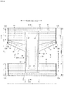
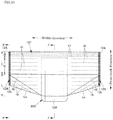
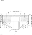
- Figs. 1 to 10(a) illustrate one example of an underpants-type disposable diaper.
- this underpants-type disposable diaper both side edges of a ventral side outer body 12F in a width direction and both side edges of a dorsal side outer body 12B in the width direction are joined along a vertical direction by heat sealing, ultrasonic welding, or the like to form cylindrical-shaped outer bodies 12F and 12B.
- a front end portion of an inner body 200 is connected by a hot-melt adhesive or the like to an inner surface of a central portion of the ventral side outer body 12F in the width direction
- a back end portion of the inner body 200 is connected by the hot-melt adhesive or the like to the inner surface of a central portion of the dorsal side outer body 12B in the width direction.
- Reference sign 12A indicates a joined section (side seal portion) of the ventral side outer body 12F and the dorsal side outer body 12B.
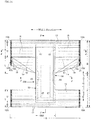
- reference sign Y indicates the entire length (vertical length from an edge of a waist opening in the front panel F to an edge of the waist opening in the back panel B) of the diaper in the open state
- reference sign X indicates the entire width of the diaper in the open state.
- the inner body 200 is a part absorbing and retaining excretion such as urine, and the outer bodies 12F and 12B are parts for supporting the inner body 200 for the wearer's body.
- the dot patterns in the drawing represent a hot-melt adhesive for joining the constituent members. Alternatively, the members may be joined by welding process (heat sealing or ultrasonic sealing).
- the hot-melt adhesive may be applied in a solid, bead, curtain, summit, or spiral pattern. Instead of or in addition to this, for fixation of the resilient and elastic members, the hot-melt adhesive may be applied to the outer peripheral surface of the resilient and elastic members by the means of a comb gun or a Sure-Wrap application means.
- the upper opening of the outer bodies 12F and 12B constitutes a waist opening through which the wearer's waist is passed.
- Parts surrounded, respectively, by lower edges of the outer bodies 12F and 12B and side edges of the inner body 200 at both sides of the inner body 200 in the width direction constitute leg openings through which the wearer's legs are passed.
- the inner body 200 With respective welded portions 12A taken off and the outer bodies 12F and 12B opened, the inner body 200 has a narrower shaped intermediate portion in the front-back direction, as illustrated in Figs. 1 and 2 .
- the inner body 200 extends from the dorsal side to the ventral side, passing through and covering the crotch portion.
- the inner body 200 is a portion receiving and absorbing excretion and retaining the liquid thereof, and the outer bodies 12F and 12B are portions to support the inner body 200 to the wearer.
- the inner body 200 may be formed in any shape, although it is rectangular in the illustrated form.
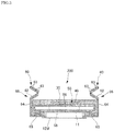
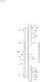
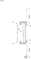
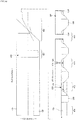
- the inner body 200 is a main body part with absorptive function that includes a top sheet 30 on the wearer's body side, a liquid impervious sheet 11, and an absorbent element 50 intervening between these sheets, as illustrated in Figs. 3 to 5 .
- Reference sign 40 indicates an interlayer sheet (second sheet) provided between the top sheet 30 and the absorbent element 50 to move quickly the liquid having passed through the top sheet 30 to the absorbent element 50 and to prevent reflowing.
- Reference sign 60 indicates three-dimensional gathers 60 standing from the both sides of the inner body 200 toward the wearer's body to prevent excretion from leaking toward the both sides of the inner body 200.
- the top sheet 30 is pervious to liquid and may be a porous or non-porous non-woven fabric or a porous plastic sheet, for example.
- raw fibers for the non-woven fabric may be synthetic fibers based on olefin such as polyethylene and polypropylene, polyester, or polyamide, reproduced fibers of rayon, cupra, or the like, natural fibers of cotton or the like, and mixed fibers or composite fibers of two or more of the foregoing fibers.
- the non-woven fabric may be produced by any processing method.
- the processing method may be any of publicly known methods such as spun-lacing, spun-bonding, thermal bonding, melt-blowing, needle-punching, air-through processing, and point-bonding, for example.
- spun-bonding and spun-lacing are preferred.
- air-through processing, point-bonding, and thermal bonding are preferred.
- the top sheet 30 may be composed of a single sheet or a layered sheet obtained by sticking two or more sheets to each other. Similarly, the top sheet 30 may be composed of a single sheet or two or more sheets in a planar direction.
- both sides of the top sheet 30 are extended up to the back side of the absorbent element 50 through between the liquid impervious sheet 11 and the three-dimensional gathers 60, and are adhered to the liquid impervious sheet 11 and the three-dimensional gathers 60 by a hot-melt adhesive or the like to prevent liquid penetration.
- the interlayer sheet 40 higher in liquid permeation speed than the top sheet 30 may be provided.
- the interlayer sheet 40 can not only move the liquid quickly to the absorber with enhancement in absorption performance of the absorber but also prevent a "reflowing" phenomenon of the absorbed liquid from the absorber to keep the top sheet 30 in a dry state at any time.
- the interlayer sheet 40 may not be provided.
- the interlayer sheet 40 may be made from the same material as that for the top sheet 30, or spun-laced, spun-bonded, SMS, or pulp non-woven fabric, or mixture sheet of pulp and rayon, point-bonded or crape paper, for example.
- air-through non-woven fabric is preferred due to its bulkiness.
- the air-through non-woven fabric preferably uses composite fibers of core-sheath structure.
- the resin for the core is acceptably polypropylene (PP) but preferably polyester (PET) with high rigidity.
- the basis weight of the fiber is preferably 20 to 80 g/m 2 , more preferably 25 to 60 g/m 2 .
- the fineness of raw fibers for the non-woven fabric is preferably 2.2 to 10 dtex.
- all or some composite fibers of the raw fibers are preferably eccentric fibers with cores not centered, hollow fibers, or eccentric and hollow fibers.
- the interlayer sheet 40 in the illustrated form is centered on an absorber 56 and is narrower than the absorber 56 in the width direction. Alternatively, the interlayer sheet 40 may be provided over the entire width of the absorber 56. The interlayer sheet 40 may be the same in length as the absorber 56, or may be shorter than the absorber 56, falling within the central area for receiving liquid.
- the liquid impervious sheet 11 may be a plastic film made from an olefin resin such as polyethylene and polypropylene, a laminate non-woven fabric with a plastic film on the surface of non-woven fabric, a layered sheet in which non-woven fabric and the like is laid on a plastic film.
- the liquid impervious sheet 11 is preferably made from a liquid-impervious and moisture-pervious material that has been favorably used in recent years for the viewpoint of prevention of stuffiness.
- the liquid impervious sheet 11 may be a non-woven fabric of microdenier fibers, or may be a liquid-impervious sheet that is formed without the use of a plastic film, by enhancing leak-proof performance by reducing the size of gaps between fibers with the application of heat or pressure or by coating the sheet with a high-water absorption resin, a hydrophobic resin, or a water repellent agent.
- the liquid impervious sheet 11 is preferably extended through the both sides of the absorbent element 50 to the both sides of the absorbent element 50 at the top sheet 30 side.
- the appropriate width of the extended portion is about 5 to 20 mm at each of the right and left sides.
- An excretion indicator changing in color by absorption of liquid may be provided at the inside of the liquid impervious sheet 11, in particular, on the side surface of the absorber 56.
- the three-dimensional gathers 60 are belt-like members extended entirely along the both sides of the inner body 200 in the front-back direction.
- the three-dimensional gathers 60 are provided to shut off urine or loose stool moving laterally over the top sheet 30 to prevent lateral leakage of the liquid.
- the three-dimensional gathers 60 stand on the sides of the inner body 200.
- Each of the three-dimensional gathers 60 stands obliquely toward the central portion in the width direction at the base portion, and stands obliquely toward the outside in the width direction from the intermediate portion to the forward edge.
- each of the three-dimensional gathers 60 is formed such that a belt-like gather sheet 62 having the same length as the length of the inner body 200 in the front-back direction is folded back in two in the width direction, and a plurality of elongated resilient and elastic members 63 is fixed in the extended state along the longitudinal direction with spacing therebetween in the width direction between the sheets at a folded portion and its neighborhood.
- the base portions (ends opposite to the sheet folded portion in the width direction) of the three-dimensional gathers 60 positioned opposite to the forward edge portions constitute attachment portions 65 fixed to the under side surface of the inner body 200 at side edges.
- the portions of the three-dimensional gathers 60 other than the attachment portions 65 constitute protrusions 66 (folded portions) that protrude from the attachment portions 65.
- the protrusions 66 include the base portions toward the central side in the width direction and the edge portions that are folded back from the edges of the base portions toward the outside in the width direction.
- this form uses the three-dimensional gathers of surface-touching type, three-dimensional gathers (not illustrated) of a line-touching type that are not folded back toward the outside in the width direction may also be used.
- the gather sheet 62 may be preferably formed by applying a water repellent treatment with silicone or the like as necessary to flexible non-woven fabric excellent in uniformity and concealing performance such as spun-bonded non-woven fabric (SS, SSS, or the like), SMS non-woven fabric (SMS, SSMMS, or the like), and melt-blown non-woven fabric.
- the basis weight of the fibers is preferably about 10 to 30 g/m 2 .
- the elongated resilient and elastic members 63 may be rubber threads or the like. In the case of using spandex rubber threads, the fineness of the threads is preferably 470 to 1240 dtex, more preferably 620 to 940 dtex.
- the extension ratio of the threads at the time of fixing is preferably 150 to 350%, more preferably 200 to 300%.
- a water-proof film 64 may intervene in the gather sheet folded in two as illustrated in the drawing.
- the number of elongated resilient and elastic members 63 provided in the free portions of the three-dimensional gathers 60 is preferably two to six, more specifically three to five.
- the arrangement spacing 60d is appropriately 3 to 10 mm. According to this configuration, the diaper is likely to touch the skin by surface with arrangement of the elongated resilient and elastic members 63.
- the elongated resilient and elastic members 63 may be arranged not only at the edge portions but also at the base portions.
- the attachment portions 65 of the three-dimensional gathers 60 may be fixed to appropriate members in the inner body 200 such as the top sheet 30, the liquid impervious sheet 11, and the absorbent element 50.
- the contraction force of the elongated resilient and elastic members 63 acts to make the both end portions in the front-back direction closer to each other.
- the both end portions of the protrusions 66 in the front-back direction are fixed so as not to stand, whereas the middle portions between the both ends of the protrusions 66 are non-fixed free portions. Accordingly, only the free portions stand to touch the wearer's body as illustrated in Fig. 3 .
- the attachment portions 65 are positioned on the back surface of the inner body 200, the three-dimensional gathers 60 stand and open outward in the width direction at the crotch portion and its neighborhood. Accordingly, the three-dimensional gathers 60 are brought into surface contact around the legs to produce an improved fit.
- the dimensions of the three-dimensional gathers 60 can be decided as appropriate.
- the standing height W6 width of the protrusions 66 in an open state
- the separation distance W3 between the folds at the innermost side is preferably 60 to 190 mm, more preferably 70 to 140 mm in the flatly folded state where the three-dimensional gathers 60 are made parallel to the surface of the top sheet 30.
- the three-dimensional gathers may be provided doubly (in two rows) at each of the right and left sides of the inner body 200.
- the absorbent element 50 has the absorber 56 and a wrapping sheet 58 for wrapping the entire absorber 56.
- the wrapping sheet 58 may not be provided.
- the absorber 56 may be formed from a fiber assembly.
- the fiber assembly may be fluff pulp fibers or accumulated short fibers such as synthetic fibers, or a filament assembly obtained by opening tows (fiber bundles) of synthetic fibers such as cellulose acetate, as necessary.
- the basis weight of fluff pulp or accumulated short fibers may be about 100 to 300 g/m 2
- the basis weight of a filament assembly may be about 30 to 120 g/m 2 , for example.
- the fineness of synthetic fibers is, for example, 1 to 16 dtex, preferably 1 to 10 dtex, more preferably 1 to 5 dtex.
- the filaments may be non-crimped fibers but are preferably crimped fibers.
- the number of crimps in the crimped fibers may be, for example, about 5 to 75 per inch, preferably about 10 to 50 per inch, more preferably about 15 to 50 per inch.
- the crimped fibers are evenly crimped in many cases.
- High-absorbent polymer particles are preferably dispersed and held in the absorber 56.
- the absorber 56 may be rectangular in shape but preferably has an hourglass shape having a front end portion, a back end portion, and a narrower portion that is positioned between the front and back end portions and is narrower than the two end portions as illustrated in Fig. 1 to improve the absorber 56 and the three-dimensional gathers 60 in a fit of the edges around the legs.
- the dimensions of the absorber 56 can be decided as appropriate. Nevertheless, the absorber preferably extends to the peripheral edges or their neighborhoods of the inner body in the front-back direction and the width direction. Reference sign 56X indicates the width of the absorber 56.
- the absorber 56 may partially or entirely contain high-absorbent polymer particles.
- the high-absorbent polymer particles include "powders" as well as “particles".
- the diameter of the high-absorbent polymer particles 54 may be the same as that of particles for general use in this type of absorbent article.
- the ratio of particles that remain on a sieve after sieving (shaking for five minutes) with a standard sieve (JIS Z8801-1:2006) of 500 ⁇ m is preferably 30 weight % or less.
- the ratio of particles that remain on the sieve after sieving (shaking for five minutes) with the standard sieve (JIS Z8801-1:2006) of 180 ⁇ m is preferably 60 weight % or more.
- the high-absorbent polymer particles may be based on starch, cellulose, or synthetic polymer.
- the high-absorbent polymer particles may be made of a starch-acrylic acid (salt) graft copolymer, a saponified material of starch-acrylonitrile copolymer, a crosslinking substance of carboxymethyl-cellulose sodium, an acrylic acid (salt) polymer, or the like.
- the high-absorbent polymer particles are preferably used in a general particulate form but may be used in another form.
- the water absorption rate of the high-absorbent polymer particles is preferably 70 seconds or less, more preferably 40 seconds or less. When the water absorption is too late, the liquid, which has supplied to the absorber 56, is more likely to flow back to the outside of the absorber 56 (so called "reflowing").
- the gel strength of the high-absorbent polymer particles is preferably 1000 Pa or more. Accordingly, it is possible to suppress effectively a sticky feeling of the absorber 56 after liquid absorption even when the absorber 56 is of high bulk.
- the basis weight of the high absorbent polymer particles can be decided as appropriate depending on the absorption volume required in the use of the absorber 56. Therefore, although being not specified absolutely, the basis weight may be 50 to 350 g/m 2 . When the basis weight of the polymer is lower than 50g/m 2 , it is hard to assure the absorption volume. When the basis weight of the polymer exceeds 350g/m 2 , the effect becomes saturated.
- the high-absorbent polymer particles can be adjusted in dispersing density or dispersing quantity along the planar direction of the absorber 56.
- the dispersing quantity of the high-absorbent polymer particles may be larger in the excretion region than the other regions.
- the dispersing density (quantity) of the high-absorbent polymer particles may be increased at the front side of the product for male, and may be increased at the central part of the product for female.
- the polymer may not be provided locally (in spots for example) in the absorber 56 in the planar direction.
- the material thereof may be tissue paper, in particular, crape paper, non-woven fabric, polyethylene-laminated non-woven fabric, a porous sheet, or the like.
- the material sheet is desirably configured to retain the high-absorbent polymer particles.
- the hydrophilic SMS non-woven fabric (SMS, SSMMS, or the like) is preferred in particular and its material may be polypropylene, polyethylene/polypropylene composite, or the like.
- the basis weight of the material is desirably 5 to 40 g/m 2 , in particular 10 to 30 g/m 2 .
- the form of wrapping by the wrapping sheet 58 can be decided as appropriate. Nevertheless, from the viewpoint of ease of producing and prevention of leakage of the high-absorbent polymer particles from the front and back end edges, the wrapping sheet 58 preferably wraps the absorber 56 in a cylindrical form to surround the front and back surfaces and both side surfaces of the absorber 56, and has front and back edges extended off from the upper side surface and under side surface of the absorber 56 so that the extended portions are crushed in the upper side-under side direction and joined together by a joint means such as a hot-melt adhesive.
- a crotch portion cover sheet 12M so as to cover a part of exposed portion of the inner body 200 (for example, along the entire front-back direction of the exposed portion between the ventral side outer body 12F and the dorsal side outer body 12B but not extending to the front and back ends of the inner body 200, or both side edges in the width direction not reaching the both side edges of the inner body 200) or the entire inner body 200.
- a material for the crotch portion cover sheet 12M similar to that of the outer bodies 12F and 12B may be used as explained below.
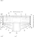
- the outer bodies 12F and 12B have waist portions T having the side seal portions 12A and determined as vertical areas (vertical areas from the waist opening to the upper ends of the leg openings) and an intermediate portion L determined as a front-back area of a portion forming the leg openings (between a vertical region of the ventral-side outer body 12F having the side seal portions 12A and a vertical region of the back-side outer body 12B having the side seal portions 12A).
- the waist portions T are conceptually divided into "waist edge portions" W forming the edge of the waist opening and "lower waist portions" U as the portions under the waist edge portions W.
- portions closer to the waist opening WO than to boundaries closest to the waist opening WO correspond to the waist edge portions W.
- portions closer to the waist opening WO than to the absorber 56 or to the inner body 200 correspond to the waist edge portions W.
- the lengths of these portions in the vertical direction vary depending on the size of the product and can be decided as appropriate.
- the length of the waist edge portion W may be 15 to 40 mm, and the length of the lower waist portion U may be 65 to 120 mm.
- the intermediate portion L can be also omitted or the intermediate portions L can be provided on both of the ventral-side outer body and the back-side outer body.
- the intermediate portion L is provided on only the back-side outer body 12B and covers buttocks.
- the outer bodies 12F and 12B are constituted by the ventral-side outer body 12F and the back-side outer body 12B, and the ventral-side outer body 12F and the back-side outer body 12B are not continuous at the leg sides and are separated from each other.
- a separation distance L8 therebetween may be set to approximately 150 to 250 mm.
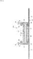
- the outer body 12 is formed by joining the two sheet materials 12S and 12H with an adhesive such as a hot-melt adhesive as illustrated in Figs. 3 to 5 .
- the inner sheet material 12H positioned inside extends up to the edge of the waist opening, whereas the outer sheet material 12S wraps around the edge of the inner sheet material 12H on the waist side and folds back toward the inside.
- Folded part 12w is extended to cover the upper end portion of the inner body 200 on the waist side.
- the sheet materials 12S and 12H are sheet-like, but they are preferably formed from non-woven fabric.
- the raw fibers may be synthetic fibers based on olefin such as polyethylene and polypropylene, polyester, or polyamide, reproduced fibers of rayon or cupra, natural fibers of cotton or the like, or mixed fibers or composite fibers of two or more of the foregoing fibers.
- the non-woven fabric may be produced by any processing method.
- the processing method may be any of publicly known methods such as spun-lacing, spun-bonding, thermal bonding, melt-blowing, needle-punching, air-through processing, and point-bonding, for example.
- the basis weight thereof is approximately 10 to 30 g/m 2 .
- elongated resilient and elastic members 15 to 19 are provided at a predetermined extension ratio between both the sheet materials 12S and 12H, in order to enhance the fit around the wearer's waist.
- the elongated resilient and elastic members 15 to 19 may be made from a synthetic rubber or a natural rubber.
- the resilient and elastic members 15 to 19 may be elongated like threads, strings, or belts, or may be net-like or sheet-like.
- a hot-melt adhesive can be used by various application methods, or heat sealing or ultrasonic adhesion can be used.
- a plurality of waist edge resilient and elastic members 17 is fixed at the waist edge portion W in the extended state along the width direction at a predetermined extension ratio with spacing therebetween in the up-down direction in such a manner as to be entirely continuous in the width direction.
- One or more of the waist edge resilient and elastic members 17 in a region adjacent to the lower waist portion U may overlap the inner body 200 or may be provided on a lateral side of a center portion in the width direction overlapping with the inner body 200 so as to be continuous in the width direction.
- the waist edge resilient and elastic members 17, about 3 to 22 rubber threads with a fineness of 155 to 1880 dtex, in particular about 470 to 1240 dtex (This is applied in the case of a synthetic rubber.
- a cross-section area of 0.05 to 1.5 mm 2 , in particular about 0.1 to 1.0 mm 2 ) are preferably fixed at an extension ratio of 150 to 400%, in particular about 220 to 320%, with spacing of 4 to 12 mm.
- All of the waist edge resilient and elastic members 17 may not be equal in thickness and extension ratio.
- the resilient and elastic members may be different in fineness and extension ratio between the upper and lower sides of the waist edge portions W.
- a plurality of lower waist portion resilient and elastic members 15 and 18 composed of elongated resilient and elastic members is fixed in the extended state along the width direction at a predetermined extension ratio with up-down direction space therebetween in such a manner as to be entirely continuous in the width direction, at upper sides and at the lateral sides of central portions of the lower waist portions U in the width direction overlapping the inner body 200.
- the intermediate portion L in the dorsal side outer body 12B is folded once or plural times in a zigzag manner in the front-back direction at the side edge and fixed by a hot-melt adhesive or the like to form a folded part 12W.
- the folded part 12W is gradually unfolded downward with increasing proximity to the width-direction central portion, and the folded part 12W is fixed by a hot-melt adhesive or the like to the inner body 200 in a halfway or completely downward unfolded state at the width-direction central portion.
- the fixed portion of the folded part 12W is shown with reference sign 12k.
- oblique resilient and elastic members 19 composed of elongated resilient and elastic members fixed in the extended state are provided in the direction from the folded part 12W to the side edge under the folded part 12W in the inner body 200.
- the oblique resilient and elastic members 19 are provided on the lateral sides of the the width direction overlapping the inner body 200, and are set along the width direction when the folded part 12W is unfolded.
- a plurality of intermediate portion resilient and elastic members 16 constituted of elongated resilient and elastic members continuous in the width direction is fixed at up-down direction intervals and in the state extended along the width direction at a predetermined extension ratio on the lateral sides of the width direction central portion overlapping the inner body 200.
- edges Le of the leg openings disposed on the lateral sides of the inner body 200 are faced in an obliquely upward direction toward the side edge portions in the dorsal side outer body 12B, and the oblique resilient and elastic members 19 are fixed in the extended state along the edges. Accordingly, the edges Le of the leg openings fit closely and favorably around the round buttocks of the wearer.
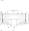
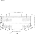
- Fig. 9(a) is a photograph of a dummy doll wearing a sample in the form illustrated in Figs. 1 to 8 and 10(a) .
- FIG. 9(b) is a photograph of a dummy doll wearing an outer halved-structure commercial product not having the folded and unfolded structure or the oblique resilient and elastic members 19.
- the sample according to the present invention has the edges Le of the leg openings in the dorsal side outer body 12B fitting favorably to the round buttocks and covering favorably the buttocks, as compared to the commercial products.
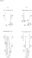
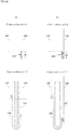
- the folded part 12W and the oblique resilient and elastic members 19 may be provided only on the dorsal side outer body 12B as illustrated in Figs. 10(a) , 13 , 20 , and 21(a) , as well as on both the ventral side outer body 12F and the dorsal side outer body 12B as illustrated in Figs. 10(b) , 11 , 12 , and 22 .
- the folded part 12W and the oblique resilient and elastic members 19 may be provided only on the ventral side outer body 12F as illustrated in Fig. 21(b) .
- the folded part 12W may be folded in a direction toward the inside of the diaper as illustrated in Figs. 10 , 11 , 12(b) , 13 , 20 , and 21(b) , as well as in a direction toward the outside of the diaper as illustrated in Figs. 12(a) and 21(a) .
- the folded part 12W is formed by folding inward as in the former case, the unfolded portion of the folded part 12W is unlikely to lift from the skin and fits tightly to the skin.
- the folded part 12W is provided in the dorsal side outer body 12B, the unfolded portion of the folded part 12W is formed in a three-dimensional shape to cover the round buttocks.
- the folded part 12W is formed by folding outward as in the latter case, the unfolded portion of the folded part 12W fits softly to the skin by weak force.
- the number of folds in the folded part 12W can be decided as appropriate, and is preferably one as illustrated in Figs. 20(a) , 21 , and 22 when the diaper is produced by a production method shown in Figs. 25 to 28 described later. Meanwhile, when the folded part 12W is provided in the dorsal side outer body 12B as illustrated in Figs. 10 , 11(b) to 13 , 20 , and 21(a) , forming an even number of folds widens the unfolded portion of the folded part 12W to cover the buttocks more widely. This effect is more significant in particular when the folded part 12W is folded in the direction toward the inside of the diaper.
- the folded part 12W may be positioned under the side seal portions 12A as illustrated in Figs 10(a) , 12(b) , 13 , 20 , 21 , and 22(b) .
- the folded part 12W may be configured such that the outer body forming the folded part 12W is extended toward the leg opening side beyond the other outer body and the extended portion is folded as illustrated.
- the folded part 12W may overlap partially or entirely the side seal portions 12A as illustrated in Figs. 10(b) , 11 , 12(a) , 22(a) , and 24 .
- both the ventral side outer body 12F and the dorsal side outer body 12B may be integrally folded to the ventral side (or the dorsal side) as illustrated in Fig. 12(b) .
- the side seal portions 12A may be formed including the folded part 12W as illustrated in Figs. 10(b) to 12(a) .
- the side seal portions 12A are preferably not formed in the leg opening side region having the folded part 12W as illustrated in Figs. 10(a) , 12(b) , and 13 . Accordingly, the side seal portions 12A can be stably joined to prevent reduction in productivity.
- the folded part 12W may be fixed with an adhesive 12p and by welding process such that the folded part 12W is first fixed with the adhesive 12p and then the side seal portions 12A and the folded part 12W are integrally welded as illustrated in Figs. 18 to 20(a) . Otherwise, the folded part 12W may be fixed by welding integrally with the side seal portions 12A without the use of the adhesive as illustrated in Fig. 23 .
- the folded part 12W is positioned under the side seal portions 12A as illustrated in Figs. 18 to 20(a) , only the side seal portions 12A may be welded and the folded part 12W may be fixed only with the adhesive, although not illustrated,.
- Figs. 10 to 13 and 20 to 22 represent the lower end of the side seal portions 12A.
- the waist portion T and the intermediate portion L are corresponding to the side edge correspondence region in the present invention, and the intermediate portion L is corresponding to the lower side portion (leg side portion) of the side edge correspondence region in the present invention, respectively.
- the waist portion T is corresponding to the side edge correspondence region in the present invention
- the lower side portion (leg side portion) of the waist portion T is corresponding to the lower side portion of the side edge correspondence region in the present invention, respectively.
- the waist portion T and the intermediate portion L are corresponding to the side edge correspondence region, and the lower end portion of the waist portion T and the intermediate portion L are corresponding to the lower side portion of the side edge correspondence region, respectively.
- the dot patterns in Figs. 10 to 13 and 20 to 22 represent the hot-melt adhesive for fixing the ventral side outer body 12F and the dorsal side outer body 12B to the inner body, and the hot-melt adhesive for fixing the folded part.
- the edges Le of the leg openings obliquely face up to the edge portions.
- the edges Le of the leg openings are not cut to fit around the wearer's legs, instead the edges can be formed around the wearer's legs even by configuring the ventral side outer body 12F and the dorsal side outer body 12B to be rectangular in shape in a state where the folded part 12W is unfolded.
- trim loss in the producing of the outer bodies 12F and 12B can be completely eliminated.
- the intermediate resilient ad elastic members 16 and the oblique resilient and elastic members 19 about 2 to 10 rubber threads with a fineness of 155 to 1880 dtex, in particular about 470 to 1240 dtex (This is applied in the case of a synthetic rubber.
- a cross-section area of 0.05 to 1.5 mm 2 , in particular about 0.1 to 1.0 mm 2 ) are preferably fixed at an extension ratio of 150 to 300%, in particular about 180 to 260%, with spacing of 5 to 40 mm, in particular 5 to 20 mm.
- the inner body 200 does not contract more than necessary in the width direction, thus the diaper does not become rough with deterioration in appearance and does not decrease in absorbing performance.
- the foregoing form includes the form in which the resilient and elastic members reside only at the both sides in the width direction, and the form in which the resilient and elastic members reside crossing over the inner body 200 from one side to the other side in the width direction, but the resilient and elastic members are finely cut and exert no contraction force at the central portion overlapping the inner body 200 in the width direction(this substantially means that no resilient and elastic members are provided), and thus the contraction force of the resilient and elastic members acts only at the both sides in the width direction.
- the arrangement forms of the lower waist portion resilient and elastic members 15, 18 and the intermediate portion resilient and elastic members 16 and the oblique resilient and elastic members 19 are not limited to the foregoing examples.
- some or all of the lower waist portion resilient and elastic members 15, 18 and the intermediate portion resilient and elastic members 16 and the oblique resilient and elastic members 19 may be provided crossing over the inner body 200 from the one side to the other side in the width direction so that the stretching force acts on the entire lower waist portions U in the width direction.
- the foregoing example is based on an outer halved structure in which the ventral side outer body 12F and the dorsal side outer body 12B are separated from each other.
- the foregoing example is also applicable to an outer body 12 that is continuous from the ventral side to the dorsal side via the crotch.
- the ventral side region and dorsal side region in the continuous outer body 12 are corresponding to the ventral side outer body 12F and the dorsal side outer body 12B. Accordingly, in the present invention, they are connectively called ventral side outer part and dorsal side outer part.
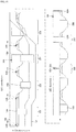
- Figs. 14 and 15 illustrate an example of a method for producing an underpants-type disposable diaper of the first form.
- This production line is formed for a lateral flow with the diaper width direction in parallel to the MD direction (machine direction or line flow direction).
- a ventral side elastic belt 12f that is to be a ventral side outer body 12F and a dorsal side elastic belt 12b that is to be a dorsal side outer body 12B are formed, and an inner body 200 produced in another line is attached to the ventral side elastic belt 12f and the dorsal side elastic belt 12b.
- the continuous members in the production process are given the same reference signs as those of the members after the production.
- the production line has a resilient member attachment step 301, a resilient member cutting step 302, a center slit step 303, a folding step 304, an inner body attachment step 305, a width increasing step 306, an inner body attachment step 307, a folding up step 308, and a side part joining step 309, and a cutoff step 310.
- the folding step 304 is more characteristic than the conventional production method.
- the resilient member attachment step 301 while a belt-like sheet material 12H of predetermined width is conveyed in the continuous direction thereof, the elongated resilient members 15 to 19 such as rubber threads are fixed in an extended state in the MD direction, with spacing in the almost entire CD direction of the sheet material 12H. Furthermore, a belt-like material 12S of predetermined width is supplied along the continuous direction thereof to top surfaces of the elongated elastic members and stuck thereto to form an elastic belt. In the illustrated example a form is assumed in which two sheet materials 12S and 12H are stuck to sandwich the resilient and elastic members 15 to 19. However, the resilient and elastic members may also be sandwiched by folding one sheet material double or in C form.
- the resilient member cutting step 302 is carried out on the formed elastic belt, as needed.
- the resilient and elastic members 15, 16, 18, and 19 positioned at a portion CT that will later overlap the inner body 200 are cut by a cutting device such as heat embossing device so that the stretching force of the resilient and elastic members 15, 16, 18, and 19 do not act on the portion CT.
- an intermediate predetermined region SL of the elastic member in the CD direction is cut along the MD direction to split the member into the ventral side elastic belt 12f and the dorsal side elastic belt 12b and expand spacing between the ventral side elastic belt 12f and the dorsal side elastic belt 12b to a predetermined distance.
- a side edge that is to be an edge Le of a leg opening
- at the center side in the CD direction of at least one of the ventral side elastic belt 12f and the dorsal side elastic belt 12b may be cut off in a curved manner, as needed, such cutting is not carried out if trim loss is completely eliminated.
- the edge Le of the leg opening may be formed so as to be along an oblique direction.
- the ventral side elastic belt 12f and the dorsal side elastic belt 12b are split separately in the cutting and splitting step 303 after being formed as an integrated elastic belt.
- the resilient and elastic members may be sandwiched by sticking two sheet materials as well as by folding one sheet material double or in C form.
- the edge side portion of the dorsal side elastic belt 12b on the ventral side elastic belt 12f side is folded once or plural times in a zigzag manner in the CD direction and fixed to form the folded part 12W.
- the fixed portion 12k of the folded part 12W can be formed by an appropriate joining means such as a hot-melt adhesive or heat sealing.
- the edge side portion of the ventral side elastic belt 12f on the dorsal side elastic belt 12b side is also folded once or plural times in a zigzag manner in the CD direction to form the folded part.
- the even number is advantageous because the portion of the folded part 12W closer to the forward edge than to the fold closest to the forward edge is faced to the opposite elastic belt (ventral side elastic belt). Accordingly, when the folded part 12W is unfolded by the connecting member 12M at the connecting step described later, no force acts in the detachment direction, and therefore the connecting is stable and turn-up or detachment is unlikely to occur.
- the portion of the folded part 12W closer to the forward edge than to the fold closest to the forward edge is connected to the opposite elastic belt by the connecting member with a predetermined space in a MD direction. That is, in the case of providing the folded part 12W in the dorsal side elastic belt 12b as in the illustrated form, the portion of the folded part 12W in the dorsal side elastic belt closer to the forward edge than to the fold closest to the forward edge is connected to the ventral side elastic belt 12f by the connecting member 12M.
- the portion of the folded part 12W in the ventral side elastic belt 12f closer to the forward edge than to the fold closest to the forward edge is connected to the dorsal side elastic belt 12b by the connecting member.
- the portion of the folded part 12W in the dorsal side elastic belt 12b closer to the forward edge than to the fold closest to the forward edge and the portion of the folded part 12W in the ventral side elastic belt 12f closer to the forward edge than to the fold closest to the forward edge are connected by the connecting member.
- the connecting can be performed by an appropriate joining means such as a hot-melt adhesive or heat sealing.
- the connecting member 12M may be a member dedicated for connecting, and in that case, there is no particular limitation on the shape and dimension of the connecting member 12M.
- the connecting means 12M in the illustrated form has a certain degree of width and is assumed to become the crotch cover sheet 12M described above in the diaper product.
- a relative space between the ventral side elastic belt 12f and the dorsal side elastic belt 12b in the CD direction is increased, and the portion of the folded part 12W connected by the connecting member 12M is pulled to unfold the folded part 12W halfway or completely. Accordingly, the oblique edge of the dorsal side elastic belt 12b becomes the edges Le of the leg openings.
- the inner body 200 produced in advance in another production line is supplied at predetermined intervals in the MD direction, a front part of the inner body 200 is joined to the ventral side elastic belt 12f and a back part of the inner body 200 is joined to the dorsal side elastic belt 12b, and the unfolded portion of the folded part is fixed to the inner body 200 to form an inner assembly body.
- the inner body is desirably fixed to the connecting member 12M as well. These joining and fixation can be performed by an appropriate means such as a hot-melt adhesive or heat sealing.
- the inner assembly body is folded at center in the CD direction such that an attachment surface of the ventral side elastic belt 12f relative to the inner body 200 and an attachment surface of the dorsal side elastic belt 12b relative to the inner body 200 overlap.
- the ventral side elastic belt 12f and the dorsal side elastic belt 12b are joined by parts to be both sides of each individual diaper to form the side seal portions 12A.
- the ventral side elastic belt 12f and the dorsal side elastic belt 12b are cut off at boundaries of each individual diaper, thereby obtaining each individual diaper DP.
- the side part joining step 309 and the cutoff step 310 can be performed simultaneously.
- the edges Le of the leg openings in the dorsal side outer body 12B positioned on the lateral sides of the inner body 200 are faced in an obliquely upward direction toward the side edge portions, and the oblique resilient and elastic members 19 are fixed in an extended state along the edges. Accordingly, the edges Le of the leg openings fit favorably around the buttocks of the wearer without slack.
- the formation of the leg openings does not need cutting, which eliminates completely trim loss in the production of the outer bodies 12F and 12B.
- the oblique resilient and elastic members 19 can be provided in an oblique direction in the product.
- the underpants-type disposable diaper having the outer body 12 continuous from the ventral side to the dorsal side via the crotch as illustrated in Fig. 13 , out of steps 301 to 310 in the foregoing production method, at least the center slit step 303 and the connecting step 305 are not provided but a punching step for forming leg openings in one large elastic belt is provided instead. In this case, cut pieces are generated but the connecting member 12M is not needed.
- the punching step may be provided at any stage between the steps 301 to 310, but is preferably provided between the resilient member cutting step 302 and the folding step 304.
- Figs. 25 and 26 illustrate an example of a production method by which the side seal portions 12A and the folded part 12W are welded integrally.
- the production line is formed for a lateral flow with the diaper width direction in parallel to the MD direction (machine direction or line flow direction).
- the ventral side elastic belt 12f to be the ventral side outer body 12F and the dorsal side elastic belt 12b to be the dorsal side outer body 12B are formed, and the inner body 200 produced in another line is attached to the ventral side elastic belt 12f and the dorsal-side elastic belt 12b.
- the members continuous in the production process are given the same reference signs of the members after the production.
- the production line includes a resilient member attachment step 401, a resilient member cutting step 402, an outer body cutting and splitting step 403, an inner body attachment step 407, a folding up step 408, an adhesive application step 404, a folding step 405, and a side part joining step 409, a cutoff step 410.
- the folding step 405 is characteristic in particular as compared to the conventional production method.
- the resilient and elastic members 15 to 19 such as rubber threads are fixed in an extended state in the MD direction to almost the entire sheet material 12S at a space therebetween in the CD direction, and the belt-like sheet material 12H of a predetermined width is supplied and stuck to the upper surface of the sheet material 12S along the continuous direction thereof, thereby forming the elastic belt.
- the two sheet materials 12S and 12H are stuck to sandwich the resilient and elastic members 15 to 19.
- one sheet material may be folded double or in C form to sandwich the resilient and elastic members.
- at least one end of one sheet material in the CD direction may be folded toward the back side (opposite to the opposed surface) of the other sheet material.
- the resilient member cutting step 402 is performed as needed on the formed elastic belt to cut by a cutting device such as a heat embossing device the resilient and elastic members 15, 16, 18, and 19 positioned at the portion CT to overlap the inner body 200 later at a predetermined space therebetween in the MD direction so that the stretching force of the resilient and elastic members 15, 16, 18, and 19 does not act on the portion CT.
- a cutting device such as a heat embossing device the resilient and elastic members 15, 16, 18, and 19 positioned at the portion CT to overlap the inner body 200 later at a predetermined space therebetween in the MD direction so that the stretching force of the resilient and elastic members 15, 16, 18, and 19 does not act on the portion CT.
- a predetermined central site SL of the elastic belt in the CD direction is cut by a slitter along the MD direction to split the elastic belt into the ventral side elastic belt 12f and the dorsal side elastic belt 12b, and the space between the ventral side elastic belt 12f and the dorsal side elastic belt 12b is increased to a predetermined distance.
- a CD direction central side edge to be the edges Le of the leg openings
- the cutting is not to be performed to eliminate completely trim loss.
- the edges Le of the leg openings can be shaped in an oblique direction as described later.
- the integrally-formed elastic belt is split into the ventral side elastic belt 12f and the dorsal side elastic belt 12b at the cutting and splitting step 403.
- the ventral side elastic belt 12f and the dorsal side elastic belt 12b may be formed from separate sheet materials to omit the cutting and splitting step 404.
- the two sheet materials may be stuck to sandwich the resilient and elastic members, one sheet material may be folded double or in C form to sandwich the resilient and elastic members, or at least one end of one of the sheet materials in the CD direction may be folded toward the back side (opposite of the opposed surface) of the other sheet material.
- the inner body 200 produced in a simultaneous parallel manner in another line by a publicly known method is supplied at predetermined intervals in the MD direction, and the front part of the inner body 200 is joined to the ventral side elastic belt 12f and the back part of the inner body 200 is joined to the dorsal side elastic belt 12b, thereby forming the inner assembly body.
- joining and fixing operations can be performed by an appropriate means such as a hot-melt adhesive or heat sealing.
- the inner assembly body is folded at center in the CD direction such that the attachment surface of the ventral side elastic belt 12f relative to the inner body 200 and the attachment surface of the dorsal side elastic belt 12b relative to the inner body 200 overlap.
- the adhesive 12p such as a hot-melt adhesive is applied to the leg opening side portion of the dorsal side elastic belt 12b at a folded part formative position with a predetermined space in the MD direction.
- the leg opening side portion of the dorsal side elastic belt 12b is folded in the CD direction and fixed with the previously applied adhesive 12p, thereby forming the folded part 12W. Accordingly, the oblique edge of the dorsal side elastic belt 12b constitutes the edges Le of the leg openings.
- the ventral side elastic belt 12f and the dorsal side elastic belt 12b are joined at the both sides of each individual diaper to form the side seal portions 12A.
- the ventral side elastic belt 12f and the dorsal side elastic belt 12b are cut at boundaries of each individual diaper to obtain each individual diaper DP.
- the side part joining step 409 and the cutoff step 410 may be performed in sequence or simultaneously.
- the side seal portions 12A and the folded part 12W may be welded integrally as in the illustrated form, or when the folded part 12W is positioned under the side seal portions 12A, the folded part 12W may not be welded.
- the adhesive application step 404 and the folding step 405 are performed between the folding up step 408 and the side part joining step 409.
- the adhesive application step 404 and the folding step 405 may be performed anywhere between the inner body attachment step 407 and the cutoff step 410.
- Fig. 27 illustrates a production flow of forming the folded part 12W in the form illustrated in Fig. 24 .
- the leg opening side portion of the dorsal side elastic belt 12b is folded in the CD direction over the ventral side elastic body 12f, and is fixed with the previously applied adhesive 12p to form the folded part 12W.
- This form is suitable for the case in which the angle of the edges Le of the leg openings is to be higher.
- the adhesive application step 404 and the folding step 405 are performed after the folding up step 408. In the other respects, this form is the same as the form illustrated in Figs. 25 and 26 .
- Fig. 28 illustrates a production flow of forming the folded part 12W in the form illustrated in Fig. 23 .
- the adhesive application step 404 is omitted.
- the folding step 405 while the folded state is held, the joining of the ventral side elastic belt 12f and the dorsal side elastic belt 12b and the fixation of the folded part 12W are performed simultaneously by welding at the side part joining step 409.
- This provides advantages that the production method can be simplified, the material cost can be reduced by the reduction in the use of the adhesive, and the hardening of the outer bodies 12F and 12B can be suppressed by the reduction in the use of the adhesive.
- this form is the same as the form illustrated in Figs. 25 and 26 .
- the leg opening side portion of the ventral side elastic belt 12f is folded in the CD direction and fixed to form the folded part.
- At least the center slit step 403 is not provided in the foregoing production method including the steps 401 to 410.
- a punching step is provided to form leg openings in one large elastic belt.
- the punching step may be provided at any stage, but is preferably provided between the resilient member attachment step 401 and the inner body attachment step 407.
- the present invention is usable to an underpants-type disposable diaper and a production method therefor.
Landscapes
- Health & Medical Sciences (AREA)
- Engineering & Computer Science (AREA)
- Life Sciences & Earth Sciences (AREA)
- Biomedical Technology (AREA)
- Heart & Thoracic Surgery (AREA)
- Vascular Medicine (AREA)
- Epidemiology (AREA)
- Animal Behavior & Ethology (AREA)
- General Health & Medical Sciences (AREA)
- Public Health (AREA)
- Veterinary Medicine (AREA)
- Manufacturing & Machinery (AREA)
- Mechanical Engineering (AREA)
- Botany (AREA)
- Absorbent Articles And Supports Therefor (AREA)
Claims (13)
- Unterhosenartige Einwegwindel, umfassend:Einen äußeren Körper (12F, 12B), der einen bauchseitigen äußeren Teil und einen rückseitigen äußeren Teil und eine Taillenaussparung aufweist, die durch verbundene Seitenrandabschnitte des bauchseitigen äußeren Teiles und Seitenrandabschnitte des rückseitigen äußeren Teiles an beiden Breitenrichtungsseiten gebildet wird; undeinen inneren Körper (200), der ein Vorderteil, das mit einem Breitenrichtungszentralbereich des bauchseitigen äußeren Teiles verbunden ist, und ein Hinterteil, das mit einem Breitenrichtungszentralbereich des rückseitigen äußeren Teiles verbunden ist, aufweist und durch den Schritt eines Trägers führt, Ränder von Beinöffnungen (Le), die zumindest teilweise durch Ränder von Teilen des äußeren Körpers (12F, 12B) gebildet werden, positioniert an beiden Breitenrichtungsseiten des inneren Körpers (200), wobeiin mindestens einem von dem bauchseitigen äußeren Teil und dem rückseitigen äußeren Teil Teile an einem unteren Rand eines Seitenrandentsprechungsbereiches, der den Seitenrandabschnitten in einer vorne-hinten-Richtung entspricht, positioniert an den beiden Breitenrichtungsseiten des inneren Körpers, die Ränder der Beinöffnungen (Le) bilden, ein unterer Teil des Seitenrandentsprechungsbereiches als ein gefalteter Teil (12W) eingeführt ist, der in der vorne-hinten-Richtung einmal oder viele Male in einer Zigzagweise gefaltet ist und an den Seitenrandabschnitten fixiert ist, der gefaltete Teil nach unten fortschreitend mit zunehmender Nähe zu der Breitenrichtungzentralseite entfaltet ist, und der gefaltete Teil (12W) in auf halbem Wege oder vollständig nach unten entfaltetem Zustand an dem inneren Körper (200) in dem Breitenrichtungzentralabschnitt fixiert ist und gestreckte, versteckte, dehnfähige und elastische Teile in einem ausgedehnten Zustand in einer Richtung von dem gefalteten Teil zu den Seitenrändern des inneren Körpers unterhalb des gefalteten Teiles fixiert werden.
- Unterhosenartige Einwegwindel nach Anspruch 1, wobei das Verbinden zwischen den Seitenrandabschnitten des bauchseitigen äußeren Teiles und den Seitenrandabschnitten des rückseitigen äußeren Teiles und die Fixierung des gefalteten Teiles ganzheitlich durch ein Schweißverfahren durchgeführt wird.
- Unterhosenartige Einwegwindel nach Anspruch 1, wobei die Seitenrandabschnitte des bauchseitigen äußeren Teiles und die Seitenrandabschnitte des rückseitigen äußeren Teiles durch Schweißen verbunden werden, aber zumindest in einem Bereich mit dem gefalteten Teil (12W) nicht durch das Schweißen verbunden werden.
- Unterhosenartige Einwegwindel nach irgendeinem der Ansprüche 1 bis 3, wobei der äußere Körper (12F, 12B) durch Verbinden des bauchseitigen äußeren Körpers (12F), der den bauchseitigen äußeren Teil bildet, und des rückseitigen äußeren Körpers (12B), der den rückseitigen äußeren Teil bildet, an beiden Seiten gebildet wird und der bauchseitige äußere Körper (12F) und der rückseitige äußere Körper (12B) voneinander getrennt sind ohne an Stelle des Schrittes durchgängig zu sein.
- Unterhosenartige Einwegwindel nach Anspruch 4, wobei die Form von mindestens einem der äußeren Teile mit dem gefalteten Teil (12W) in dem ungefalteten Zustand rechtwinklig ist.
- Unterhosenartige Einwegwindel nach Anspruch 4 oder 5, wobei der gefaltete Teil (12W) gebildet wird, indem er nach Innen von mindestens einem der äußeren Teile gefaltet wird.
- Unterhosenartige Einwegwindel nach Anspruch 4 oder 5, wobei der gefaltete Teil (12W) durch Falten nach Außen von mindestens einem der äußeren Teile gebildet wird.
- Unterhosenartige Einwegwindel nach irgendeinem der Ansprüche 1 bis 7, wobei der mindestens eine der äußeren Teile der rückseitige äußere Teil ist.
- Unterhosenartige Einwegwindel nach Anspruch 8, wobei die Anzahl an Faltungen in dem gefalteten Teil (12W) eine gerade Anzahl ist.
- Unterhosenartige Einwegwindel nach irgendeinem der Ansprüche 1 bis 8, wobei der mindestens eine der äußeren Teile der bauchseitige äußere Teil ist und die Anzahl an Faltungen in dem gefalteten Teil (12W) eine ungerade Anzahl ist.
- Unterhosenartige Einwegwindel nach irgendeinem der Ansprüche 1 bis 10, wobei der gefaltete Teil in einem der äußeren Teile gebildet wird und der gefaltete Teil (12W) über das Äußere des anderen äußeren Teiles verlängert wird.
- Herstellungsverfahren für eine unterhosenartige Einwegwindel nach irgendeinem der Ansprüche 1 bis 11, umfassend:Einen Bildungsschritt eines elastischen Gürtels aus Bilden eines bauchseitigen elastischen Gürtels (12f) und eines rückseitigen elastischen Gürtels (12b) in welchem gestreckte, dehnfähige und elastische Teile (15-19) in einem ausgedehnten Zustand in ein gürtelähnliches, durchgängiges Lagenmaterial entlang einer kontinuierlichen Richtung davon fixiert werden;einen Faltschritt (304) während der bauchseitige elastische Gürtel (12f) und der rückseitige elastische Gürtel (12b) mit einem Raum dazwischen parallel in einer CD Richtung befördert werden aus Falten und Fixieren eines Randseitenabschnittes von mindestens einem der elastischen Gürtel auf der Seite, die dem anderen elastischen Gürtel zugewandt ist, einmal oder viele Male in einer Zigzagweise in der CD Richtung, um ein gefaltetes Teil zu bilden;einen Verbindungsschritt (305) nach dem Bildungsschritt des gefalteten Teiles aus Verbinden eines Abschnittes des gefalteten Teiles näher an dem vorderen Rand als an der Faltung am nächsten zu dem vorderen Rand mit dem anderen elastischen Gürtel durch ein Verbindungsteil mit einem vorbestimmten Raum in einer MD Richtung;einen Schritt der Weitenvergrößerung (306) nach dem Verbindungsschritt aus Erhöhen des relativen Raumes zwischen dem bauchseitigen elastischen Gürtel (12f) und dem rückseitigen elastischen Gürtel (12b) in der CD Richtung, Ziehen des Abschnittes des gefalteten Teiles, das durch das Verbindungsteil verbunden ist, um das gefaltete Teil auf halbem Wege oder vollständig zu entfalten;einen Innenkörperbefestigungsschritt (307) aus Bereitstellen eines separat hergestellten inneren Körpers (200) in Intervallen in der MD Richtung und Verbinden eines Vorderteiles des inneren Körpers mit dem bauchseitigen elastischen Gürtel und eines Hinterteiles des inneren Körpers (200) mit dem rückseitigen elastischen Gürtel und Fixieren des ungefalteten Abschnittes des gefalteten Teiles in dem ungefalteten Zustand an dem inneren Körper (200), um einen inneren Montagekörper zu bilden;einen Faltschritt (308) des Doppelfaltens des inneren Montagekörpers in der CD Richtung;
undeinen Seitenteilverbindungsschritt und Abschneideschritt (309, 310) des Verbindens des bauchseitigen elastischen Gürtels (12f) und des rückseitigen elastischen Gürtels (12b) an beiden Seitenteilen jeder individuellen Windel und des Abschneidens des bauchseitigen elastischen Gürtels (12f) und des rückseitigen elastischen Gürtels (12b) an Grenzen jeder individuellen Windel, um jede individuelle Windel zu erhalten. - Herstellungsverfahren für die unterhosenartige Einwegwindel nach Anspruch 12, wobei die Anzahl an Faltungen in dem Bildungsschritt des gefalteten Teiles eine gerade Anzahl ist.
Applications Claiming Priority (3)
| Application Number | Priority Date | Filing Date | Title |
|---|---|---|---|
| JP2014049108A JP5904605B2 (ja) | 2014-03-12 | 2014-03-12 | パンツタイプ使い捨ておむつ及びその製造方法 |
| JP2014190187A JP5988398B2 (ja) | 2014-09-18 | 2014-09-18 | パンツタイプ使い捨ておむつ及びその製造方法 |
| PCT/JP2015/055561 WO2015137130A1 (ja) | 2014-03-12 | 2015-02-26 | パンツタイプ使い捨ておむつ及びその製造方法 |
Publications (3)
| Publication Number | Publication Date |
|---|---|
| EP3117809A1 EP3117809A1 (de) | 2017-01-18 |
| EP3117809A4 EP3117809A4 (de) | 2017-12-13 |
| EP3117809B1 true EP3117809B1 (de) | 2018-11-28 |
Family
ID=54071578
Family Applications (1)
| Application Number | Title | Priority Date | Filing Date |
|---|---|---|---|
| EP15761058.5A Active EP3117809B1 (de) | 2014-03-12 | 2015-02-26 | Einwegwindel vom hosentyp und herstellungsverfahren dafür |
Country Status (7)
| Country | Link |
|---|---|
| US (1) | US10470944B2 (de) |
| EP (1) | EP3117809B1 (de) |
| KR (1) | KR102263871B1 (de) |
| CN (1) | CN106061448B (de) |
| BR (1) | BR112016020648B1 (de) |
| RU (1) | RU2661391C2 (de) |
| WO (1) | WO2015137130A1 (de) |
Families Citing this family (12)
| Publication number | Priority date | Publication date | Assignee | Title |
|---|---|---|---|---|
| JP6415399B2 (ja) * | 2015-06-25 | 2018-10-31 | ユニ・チャーム株式会社 | 使い捨て着用物品 |
| JP6351686B2 (ja) * | 2016-10-21 | 2018-07-04 | 大王製紙株式会社 | パンツタイプ使い捨ておむつ |
| US11096835B2 (en) * | 2016-12-19 | 2021-08-24 | The Procter & Gamble Company | Methods for sealing absorbent cores on absorbent articles |
| EP3630035A4 (de) * | 2017-05-31 | 2021-03-03 | Kimberly-Clark Worldwide, Inc. | Saugfähige artikel mit geschlossenen seiten und vorder- oder rückseitiger öffnung |
| KR102539552B1 (ko) | 2017-05-31 | 2023-06-05 | 킴벌리-클라크 월드와이드, 인크. | 전방 또는 후방 개방 측면-폐쇄형 흡수 용품 |
| KR102547007B1 (ko) | 2017-05-31 | 2023-06-26 | 킴벌리-클라크 월드와이드, 인크. | 전방 또는 후방 개방 측면-폐쇄형 흡수 용품 |
| EP3661471B1 (de) * | 2017-07-31 | 2023-11-29 | Kimberly-Clark Worldwide, Inc. | Elastifizierte absorbierende artikel und verfahren zur herstellung elastifizierter absorbierender artikel |
| JP7408268B2 (ja) * | 2017-08-08 | 2024-01-05 | ユニ・チャーム株式会社 | パンツ型吸収性物品 |
| JP6503448B1 (ja) * | 2017-12-28 | 2019-04-17 | ユニ・チャーム株式会社 | パンツ型吸収性物品 |
| JP7201358B2 (ja) * | 2018-07-31 | 2023-01-10 | 大王製紙株式会社 | パンツタイプ使い捨て着用物品 |
| EP3960141B1 (de) * | 2020-08-31 | 2024-02-14 | W. Pelz GmbH & Co. KG | Hygieneartikel in höschenform |
| CN112168498A (zh) * | 2020-09-27 | 2021-01-05 | 英氏控股集团股份有限公司 | 一种轻薄透气纸尿裤弹性部件及生产工艺 |
Family Cites Families (17)
| Publication number | Priority date | Publication date | Assignee | Title |
|---|---|---|---|---|
| JP3478722B2 (ja) * | 1998-01-30 | 2003-12-15 | ユニ・チャーム株式会社 | 使い捨ておむつ |
| JPH11290380A (ja) | 1998-04-06 | 1999-10-26 | Zuiko Corp | 使い捨て着用物品 |
| JP3696115B2 (ja) * | 2001-04-06 | 2005-09-14 | ユニ・チャーム株式会社 | 使い捨ておむつ |
| JP4051208B2 (ja) * | 2002-01-31 | 2008-02-20 | ユニ・チャーム株式会社 | パンツ型の使い捨て着用物品 |
| US7569039B2 (en) | 2003-11-19 | 2009-08-04 | The Procter & Gamble Company | Disposable pull-on garment |
| JP4521214B2 (ja) | 2004-03-30 | 2010-08-11 | 株式会社瑞光 | パンツタイプ着用物品の製造方法 |
| JP4439342B2 (ja) * | 2004-06-30 | 2010-03-24 | 大王製紙株式会社 | パンツ型使い捨ておむつ |
| JP5118909B2 (ja) * | 2007-07-13 | 2013-01-16 | 大王製紙株式会社 | 使い捨ておむつ |
| CN101909568B (zh) * | 2007-12-28 | 2013-03-13 | 大王制纸株式会社 | 短裤型一次性尿布 |
| CN101909564B (zh) * | 2008-05-28 | 2016-08-03 | 株式会社瑞光 | 一次性穿戴物品的制造方法 |
| JP5208781B2 (ja) | 2009-01-19 | 2013-06-12 | 大王製紙株式会社 | パンツタイプ使い捨ておむつ及びその製造方法 |
| JP5328590B2 (ja) | 2009-09-30 | 2013-10-30 | ユニ・チャーム株式会社 | 使い捨ておむつ |
| JP2011120626A (ja) | 2009-12-08 | 2011-06-23 | Kao Corp | パンツ型吸収性物品 |
| JP5596379B2 (ja) | 2010-03-16 | 2014-09-24 | 大王製紙株式会社 | パンツタイプ使い捨ておむつ |
| JP5782822B2 (ja) | 2011-05-17 | 2015-09-24 | 王子ホールディングス株式会社 | 使い捨ておむつ |
| JP5740448B2 (ja) | 2013-10-18 | 2015-06-24 | 大王製紙株式会社 | 使い捨て紙おむつ |
| JP6025215B2 (ja) * | 2014-03-12 | 2016-11-16 | 大王製紙株式会社 | パンツタイプ使い捨ておむつ |
-
2015
- 2015-02-26 KR KR1020167025170A patent/KR102263871B1/ko active IP Right Grant
- 2015-02-26 WO PCT/JP2015/055561 patent/WO2015137130A1/ja active Application Filing
- 2015-02-26 BR BR112016020648-7A patent/BR112016020648B1/pt active IP Right Grant
- 2015-02-26 US US15/119,980 patent/US10470944B2/en active Active
- 2015-02-26 EP EP15761058.5A patent/EP3117809B1/de active Active
- 2015-02-26 CN CN201580009046.2A patent/CN106061448B/zh active Active
- 2015-02-26 RU RU2016138567A patent/RU2661391C2/ru active
Non-Patent Citations (1)
| Title |
|---|
| None * |
Also Published As
| Publication number | Publication date |
|---|---|
| RU2016138567A (ru) | 2018-04-12 |
| EP3117809A1 (de) | 2017-01-18 |
| RU2661391C2 (ru) | 2018-07-16 |
| CN106061448B (zh) | 2019-07-23 |
| BR112016020648A2 (de) | 2017-08-15 |
| CN106061448A (zh) | 2016-10-26 |
| US20170049638A1 (en) | 2017-02-23 |
| KR102263871B1 (ko) | 2021-06-10 |
| US10470944B2 (en) | 2019-11-12 |
| EP3117809A4 (de) | 2017-12-13 |
| WO2015137130A1 (ja) | 2015-09-17 |
| BR112016020648B1 (pt) | 2022-05-03 |
| KR20160132847A (ko) | 2016-11-21 |
Similar Documents
| Publication | Publication Date | Title |
|---|---|---|
| EP3117813B1 (de) | Hosenähnliche einwegwindel | |
| EP3117809B1 (de) | Einwegwindel vom hosentyp und herstellungsverfahren dafür | |
| EP3117810B1 (de) | Herstellungsverfahren für unterhosenartige einwegwindel und mit besagtem verfahren hergestellte unterhosenähnliche einwegwindel | |
| EP3199132B1 (de) | Verfahren zur herstellung einer dehnbaren struktur für absorbierende artikel und dehnbare struktur für absorbierende artikel | |
| EP3162332B1 (de) | Verfahren zur herstellung vom höschenartigen wegwerfwindel sowie höschenartige wegwerfwindel | |
| EP3127517A1 (de) | Verfahren zur herstellung einer dehnbaren struktur für einen absorbierenden artikel, verfahren zur herstellung einer hosenähnlichen einwegwindel und hosenähnliche einwegwindel | |
| JP2015171502A5 (de) | ||
| EP3150182A1 (de) | Verfahren zur herstellung eines dehnbaren elastischen elements und wegwerfwindel mit dehnbarem elastischem element | |
| CN107874914B (zh) | 一次性穿着物品和有孔无纺布的粘贴方法 | |
| EP3563818B1 (de) | Verfahren zur herstellung eines saugfähigen artikels und saugfähiger artikel | |
| EP3210582A1 (de) | Hosenartige wegwerfwindel | |
| JP6315337B2 (ja) | パンツタイプ使い捨ておむつの製造方法 | |
| JP2016054989A5 (de) | ||
| JP5904605B2 (ja) | パンツタイプ使い捨ておむつ及びその製造方法 | |
| JP5988398B2 (ja) | パンツタイプ使い捨ておむつ及びその製造方法 | |
| JP2015171500A5 (de) | ||
| EP3639800B1 (de) | Überziehbare einwegwindel | |
| JP2016067435A (ja) | パンツタイプ使い捨ておむつ及びその製造方法 | |
| JP6396148B2 (ja) | パンツタイプ使い捨ておむつの製造方法及びパンツタイプ使い捨ておむつ | |
| JP2016202942A (ja) | パンツタイプ使い捨ておむつ | |
| JP6837359B2 (ja) | 使い捨ておむつ及びその製造方法 |
Legal Events
| Date | Code | Title | Description |
|---|---|---|---|
| STAA | Information on the status of an ep patent application or granted ep patent |
Free format text: STATUS: THE INTERNATIONAL PUBLICATION HAS BEEN MADE |
|
| PUAI | Public reference made under article 153(3) epc to a published international application that has entered the european phase |
Free format text: ORIGINAL CODE: 0009012 |
|
| STAA | Information on the status of an ep patent application or granted ep patent |
Free format text: STATUS: REQUEST FOR EXAMINATION WAS MADE |
|
| 17P | Request for examination filed |
Effective date: 20160921 |
|
| AK | Designated contracting states |
Kind code of ref document: A1 Designated state(s): AL AT BE BG CH CY CZ DE DK EE ES FI FR GB GR HR HU IE IS IT LI LT LU LV MC MK MT NL NO PL PT RO RS SE SI SK SM TR |
|
| AX | Request for extension of the european patent |
Extension state: BA ME |
|
| DAX | Request for extension of the european patent (deleted) | ||
| A4 | Supplementary search report drawn up and despatched |
Effective date: 20171109 |
|
| RIC1 | Information provided on ipc code assigned before grant |
Ipc: A61F 13/49 20060101ALI20171103BHEP Ipc: A61F 13/494 20060101ALI20171103BHEP Ipc: A61F 13/15 20060101AFI20171103BHEP |
|
| GRAP | Despatch of communication of intention to grant a patent |
Free format text: ORIGINAL CODE: EPIDOSNIGR1 |
|
| STAA | Information on the status of an ep patent application or granted ep patent |
Free format text: STATUS: GRANT OF PATENT IS INTENDED |
|
| INTG | Intention to grant announced |
Effective date: 20180601 |
|
| GRAS | Grant fee paid |
Free format text: ORIGINAL CODE: EPIDOSNIGR3 |
|
| GRAA | (expected) grant |
Free format text: ORIGINAL CODE: 0009210 |
|
| STAA | Information on the status of an ep patent application or granted ep patent |
Free format text: STATUS: THE PATENT HAS BEEN GRANTED |
|
| AK | Designated contracting states |
Kind code of ref document: B1 Designated state(s): AL AT BE BG CH CY CZ DE DK EE ES FI FR GB GR HR HU IE IS IT LI LT LU LV MC MK MT NL NO PL PT RO RS SE SI SK SM TR |
|
| REG | Reference to a national code |
Ref country code: CH Ref legal event code: EP |
|
| REG | Reference to a national code |
Ref country code: AT Ref legal event code: REF Ref document number: 1069377 Country of ref document: AT Kind code of ref document: T Effective date: 20181215 |
|
| REG | Reference to a national code |
Ref country code: DE Ref legal event code: R096 Ref document number: 602015020491 Country of ref document: DE |
|
| REG | Reference to a national code |
Ref country code: IE Ref legal event code: FG4D |
|
| REG | Reference to a national code |
Ref country code: NL Ref legal event code: MP Effective date: 20181128 |
|
| REG | Reference to a national code |
Ref country code: LT Ref legal event code: MG4D |
|
| REG | Reference to a national code |
Ref country code: AT Ref legal event code: MK05 Ref document number: 1069377 Country of ref document: AT Kind code of ref document: T Effective date: 20181128 |
|
| PG25 | Lapsed in a contracting state [announced via postgrant information from national office to epo] |
Ref country code: AT Free format text: LAPSE BECAUSE OF FAILURE TO SUBMIT A TRANSLATION OF THE DESCRIPTION OR TO PAY THE FEE WITHIN THE PRESCRIBED TIME-LIMIT Effective date: 20181128 Ref country code: LV Free format text: LAPSE BECAUSE OF FAILURE TO SUBMIT A TRANSLATION OF THE DESCRIPTION OR TO PAY THE FEE WITHIN THE PRESCRIBED TIME-LIMIT Effective date: 20181128 Ref country code: IS Free format text: LAPSE BECAUSE OF FAILURE TO SUBMIT A TRANSLATION OF THE DESCRIPTION OR TO PAY THE FEE WITHIN THE PRESCRIBED TIME-LIMIT Effective date: 20190328 Ref country code: FI Free format text: LAPSE BECAUSE OF FAILURE TO SUBMIT A TRANSLATION OF THE DESCRIPTION OR TO PAY THE FEE WITHIN THE PRESCRIBED TIME-LIMIT Effective date: 20181128 Ref country code: LT Free format text: LAPSE BECAUSE OF FAILURE TO SUBMIT A TRANSLATION OF THE DESCRIPTION OR TO PAY THE FEE WITHIN THE PRESCRIBED TIME-LIMIT Effective date: 20181128 Ref country code: NO Free format text: LAPSE BECAUSE OF FAILURE TO SUBMIT A TRANSLATION OF THE DESCRIPTION OR TO PAY THE FEE WITHIN THE PRESCRIBED TIME-LIMIT Effective date: 20190228 Ref country code: HR Free format text: LAPSE BECAUSE OF FAILURE TO SUBMIT A TRANSLATION OF THE DESCRIPTION OR TO PAY THE FEE WITHIN THE PRESCRIBED TIME-LIMIT Effective date: 20181128 Ref country code: BG Free format text: LAPSE BECAUSE OF FAILURE TO SUBMIT A TRANSLATION OF THE DESCRIPTION OR TO PAY THE FEE WITHIN THE PRESCRIBED TIME-LIMIT Effective date: 20190228 Ref country code: ES Free format text: LAPSE BECAUSE OF FAILURE TO SUBMIT A TRANSLATION OF THE DESCRIPTION OR TO PAY THE FEE WITHIN THE PRESCRIBED TIME-LIMIT Effective date: 20181128 |
|
| PG25 | Lapsed in a contracting state [announced via postgrant information from national office to epo] |
Ref country code: SE Free format text: LAPSE BECAUSE OF FAILURE TO SUBMIT A TRANSLATION OF THE DESCRIPTION OR TO PAY THE FEE WITHIN THE PRESCRIBED TIME-LIMIT Effective date: 20181128 Ref country code: PT Free format text: LAPSE BECAUSE OF FAILURE TO SUBMIT A TRANSLATION OF THE DESCRIPTION OR TO PAY THE FEE WITHIN THE PRESCRIBED TIME-LIMIT Effective date: 20190328 Ref country code: AL Free format text: LAPSE BECAUSE OF FAILURE TO SUBMIT A TRANSLATION OF THE DESCRIPTION OR TO PAY THE FEE WITHIN THE PRESCRIBED TIME-LIMIT Effective date: 20181128 Ref country code: GR Free format text: LAPSE BECAUSE OF FAILURE TO SUBMIT A TRANSLATION OF THE DESCRIPTION OR TO PAY THE FEE WITHIN THE PRESCRIBED TIME-LIMIT Effective date: 20190301 Ref country code: RS Free format text: LAPSE BECAUSE OF FAILURE TO SUBMIT A TRANSLATION OF THE DESCRIPTION OR TO PAY THE FEE WITHIN THE PRESCRIBED TIME-LIMIT Effective date: 20181128 |
|
| PG25 | Lapsed in a contracting state [announced via postgrant information from national office to epo] |
Ref country code: NL Free format text: LAPSE BECAUSE OF FAILURE TO SUBMIT A TRANSLATION OF THE DESCRIPTION OR TO PAY THE FEE WITHIN THE PRESCRIBED TIME-LIMIT Effective date: 20181128 |
|
| PG25 | Lapsed in a contracting state [announced via postgrant information from national office to epo] |
Ref country code: PL Free format text: LAPSE BECAUSE OF FAILURE TO SUBMIT A TRANSLATION OF THE DESCRIPTION OR TO PAY THE FEE WITHIN THE PRESCRIBED TIME-LIMIT Effective date: 20181128 Ref country code: CZ Free format text: LAPSE BECAUSE OF FAILURE TO SUBMIT A TRANSLATION OF THE DESCRIPTION OR TO PAY THE FEE WITHIN THE PRESCRIBED TIME-LIMIT Effective date: 20181128 Ref country code: IT Free format text: LAPSE BECAUSE OF FAILURE TO SUBMIT A TRANSLATION OF THE DESCRIPTION OR TO PAY THE FEE WITHIN THE PRESCRIBED TIME-LIMIT Effective date: 20181128 Ref country code: DK Free format text: LAPSE BECAUSE OF FAILURE TO SUBMIT A TRANSLATION OF THE DESCRIPTION OR TO PAY THE FEE WITHIN THE PRESCRIBED TIME-LIMIT Effective date: 20181128 |
|
| REG | Reference to a national code |
Ref country code: DE Ref legal event code: R097 Ref document number: 602015020491 Country of ref document: DE |
|
| PG25 | Lapsed in a contracting state [announced via postgrant information from national office to epo] |
Ref country code: RO Free format text: LAPSE BECAUSE OF FAILURE TO SUBMIT A TRANSLATION OF THE DESCRIPTION OR TO PAY THE FEE WITHIN THE PRESCRIBED TIME-LIMIT Effective date: 20181128 Ref country code: SK Free format text: LAPSE BECAUSE OF FAILURE TO SUBMIT A TRANSLATION OF THE DESCRIPTION OR TO PAY THE FEE WITHIN THE PRESCRIBED TIME-LIMIT Effective date: 20181128 Ref country code: SM Free format text: LAPSE BECAUSE OF FAILURE TO SUBMIT A TRANSLATION OF THE DESCRIPTION OR TO PAY THE FEE WITHIN THE PRESCRIBED TIME-LIMIT Effective date: 20181128 Ref country code: EE Free format text: LAPSE BECAUSE OF FAILURE TO SUBMIT A TRANSLATION OF THE DESCRIPTION OR TO PAY THE FEE WITHIN THE PRESCRIBED TIME-LIMIT Effective date: 20181128 |
|
| REG | Reference to a national code |
Ref country code: CH Ref legal event code: PL |
|
| PLBE | No opposition filed within time limit |
Free format text: ORIGINAL CODE: 0009261 |
|
| STAA | Information on the status of an ep patent application or granted ep patent |
Free format text: STATUS: NO OPPOSITION FILED WITHIN TIME LIMIT |
|
| PG25 | Lapsed in a contracting state [announced via postgrant information from national office to epo] |
Ref country code: SI Free format text: LAPSE BECAUSE OF FAILURE TO SUBMIT A TRANSLATION OF THE DESCRIPTION OR TO PAY THE FEE WITHIN THE PRESCRIBED TIME-LIMIT Effective date: 20181128 Ref country code: MC Free format text: LAPSE BECAUSE OF FAILURE TO SUBMIT A TRANSLATION OF THE DESCRIPTION OR TO PAY THE FEE WITHIN THE PRESCRIBED TIME-LIMIT Effective date: 20181128 Ref country code: LU Free format text: LAPSE BECAUSE OF NON-PAYMENT OF DUE FEES Effective date: 20190226 |
|
| 26N | No opposition filed |
Effective date: 20190829 |
|
| REG | Reference to a national code |
Ref country code: BE Ref legal event code: MM Effective date: 20190228 |
|
| REG | Reference to a national code |
Ref country code: IE Ref legal event code: MM4A |
|
| PG25 | Lapsed in a contracting state [announced via postgrant information from national office to epo] |
Ref country code: CH Free format text: LAPSE BECAUSE OF NON-PAYMENT OF DUE FEES Effective date: 20190228 Ref country code: LI Free format text: LAPSE BECAUSE OF NON-PAYMENT OF DUE FEES Effective date: 20190228 |
|
| PG25 | Lapsed in a contracting state [announced via postgrant information from national office to epo] |
Ref country code: IE Free format text: LAPSE BECAUSE OF NON-PAYMENT OF DUE FEES Effective date: 20190226 |
|
| PG25 | Lapsed in a contracting state [announced via postgrant information from national office to epo] |
Ref country code: BE Free format text: LAPSE BECAUSE OF NON-PAYMENT OF DUE FEES Effective date: 20190228 |
|
| PG25 | Lapsed in a contracting state [announced via postgrant information from national office to epo] |
Ref country code: MT Free format text: LAPSE BECAUSE OF NON-PAYMENT OF DUE FEES Effective date: 20190226 |
|
| PG25 | Lapsed in a contracting state [announced via postgrant information from national office to epo] |
Ref country code: CY Free format text: LAPSE BECAUSE OF FAILURE TO SUBMIT A TRANSLATION OF THE DESCRIPTION OR TO PAY THE FEE WITHIN THE PRESCRIBED TIME-LIMIT Effective date: 20181128 |
|
| PG25 | Lapsed in a contracting state [announced via postgrant information from national office to epo] |
Ref country code: HU Free format text: LAPSE BECAUSE OF FAILURE TO SUBMIT A TRANSLATION OF THE DESCRIPTION OR TO PAY THE FEE WITHIN THE PRESCRIBED TIME-LIMIT; INVALID AB INITIO Effective date: 20150226 |
|
| PG25 | Lapsed in a contracting state [announced via postgrant information from national office to epo] |
Ref country code: MK Free format text: LAPSE BECAUSE OF FAILURE TO SUBMIT A TRANSLATION OF THE DESCRIPTION OR TO PAY THE FEE WITHIN THE PRESCRIBED TIME-LIMIT Effective date: 20181128 |
|
| REG | Reference to a national code |
Ref country code: DE Ref legal event code: R084 Ref document number: 602015020491 Country of ref document: DE |
|
| PGFP | Annual fee paid to national office [announced via postgrant information from national office to epo] |
Ref country code: DE Payment date: 20231229 Year of fee payment: 10 Ref country code: GB Payment date: 20240108 Year of fee payment: 10 |
|
| REG | Reference to a national code |
Ref country code: GB Ref legal event code: 746 Effective date: 20240501 |
|
| PGFP | Annual fee paid to national office [announced via postgrant information from national office to epo] |
Ref country code: TR Payment date: 20240210 Year of fee payment: 10 Ref country code: FR Payment date: 20240103 Year of fee payment: 10 |