EP3117788A1 - Ensemble fixation osseuse plane - Google Patents
Ensemble fixation osseuse plane Download PDFInfo
- Publication number
- EP3117788A1 EP3117788A1 EP16162864.9A EP16162864A EP3117788A1 EP 3117788 A1 EP3117788 A1 EP 3117788A1 EP 16162864 A EP16162864 A EP 16162864A EP 3117788 A1 EP3117788 A1 EP 3117788A1
- Authority
- EP
- European Patent Office
- Prior art keywords
- anchor
- bone
- collet
- bone fixation
- subassembly
- Prior art date
- Legal status (The legal status is an assumption and is not a legal conclusion. Google has not performed a legal analysis and makes no representation as to the accuracy of the status listed.)
- Granted
Links
- 210000000988 bone and bone Anatomy 0.000 title claims abstract description 410
- 125000006850 spacer group Chemical group 0.000 description 29
- 238000000034 method Methods 0.000 description 10
- 238000003780 insertion Methods 0.000 description 8
- 230000037431 insertion Effects 0.000 description 8
- 241001274197 Scatophagus argus Species 0.000 description 6
- 230000000712 assembly Effects 0.000 description 4
- 238000000429 assembly Methods 0.000 description 4
- 239000012530 fluid Substances 0.000 description 2
- 239000000463 material Substances 0.000 description 2
- 230000000717 retained effect Effects 0.000 description 2
- 239000007787 solid Substances 0.000 description 2
- 229910001257 Nb alloy Inorganic materials 0.000 description 1
- 238000013459 approach Methods 0.000 description 1
- 239000011324 bead Substances 0.000 description 1
- 230000008901 benefit Effects 0.000 description 1
- 238000005422 blasting Methods 0.000 description 1
- 230000008859 change Effects 0.000 description 1
- 230000006835 compression Effects 0.000 description 1
- 238000007906 compression Methods 0.000 description 1
- 238000000605 extraction Methods 0.000 description 1
- 239000007943 implant Substances 0.000 description 1
- 238000002513 implantation Methods 0.000 description 1
- 230000008676 import Effects 0.000 description 1
- 238000002347 injection Methods 0.000 description 1
- 239000007924 injection Substances 0.000 description 1
- 230000014759 maintenance of location Effects 0.000 description 1
- 238000004519 manufacturing process Methods 0.000 description 1
- 230000013011 mating Effects 0.000 description 1
- 230000008569 process Effects 0.000 description 1
- 230000004044 response Effects 0.000 description 1
- 206010039722 scoliosis Diseases 0.000 description 1
- 239000010935 stainless steel Substances 0.000 description 1
- 229910001220 stainless steel Inorganic materials 0.000 description 1
- 230000003746 surface roughness Effects 0.000 description 1
- 210000000115 thoracic cavity Anatomy 0.000 description 1
- -1 titanium-aluminum-niobium Chemical compound 0.000 description 1
Images


Classifications
-
- A—HUMAN NECESSITIES
- A61—MEDICAL OR VETERINARY SCIENCE; HYGIENE
- A61B—DIAGNOSIS; SURGERY; IDENTIFICATION
- A61B17/00—Surgical instruments, devices or methods, e.g. tourniquets
- A61B17/56—Surgical instruments or methods for treatment of bones or joints; Devices specially adapted therefor
- A61B17/58—Surgical instruments or methods for treatment of bones or joints; Devices specially adapted therefor for osteosynthesis, e.g. bone plates, screws, setting implements or the like
- A61B17/68—Internal fixation devices, including fasteners and spinal fixators, even if a part thereof projects from the skin
- A61B17/70—Spinal positioners or stabilisers ; Bone stabilisers comprising fluid filler in an implant
- A61B17/7001—Screws or hooks combined with longitudinal elements which do not contact vertebrae
- A61B17/7035—Screws or hooks, wherein a rod-clamping part and a bone-anchoring part can pivot relative to each other
- A61B17/7038—Screws or hooks, wherein a rod-clamping part and a bone-anchoring part can pivot relative to each other to a different extent in different directions, e.g. within one plane only
-
- A—HUMAN NECESSITIES
- A61—MEDICAL OR VETERINARY SCIENCE; HYGIENE
- A61B—DIAGNOSIS; SURGERY; IDENTIFICATION
- A61B17/00—Surgical instruments, devices or methods, e.g. tourniquets
- A61B17/56—Surgical instruments or methods for treatment of bones or joints; Devices specially adapted therefor
- A61B17/58—Surgical instruments or methods for treatment of bones or joints; Devices specially adapted therefor for osteosynthesis, e.g. bone plates, screws, setting implements or the like
- A61B17/68—Internal fixation devices, including fasteners and spinal fixators, even if a part thereof projects from the skin
- A61B17/70—Spinal positioners or stabilisers ; Bone stabilisers comprising fluid filler in an implant
- A61B17/7001—Screws or hooks combined with longitudinal elements which do not contact vertebrae
- A61B17/7032—Screws or hooks with U-shaped head or back through which longitudinal rods pass
-
- A—HUMAN NECESSITIES
- A61—MEDICAL OR VETERINARY SCIENCE; HYGIENE
- A61B—DIAGNOSIS; SURGERY; IDENTIFICATION
- A61B17/00—Surgical instruments, devices or methods, e.g. tourniquets
- A61B17/56—Surgical instruments or methods for treatment of bones or joints; Devices specially adapted therefor
- A61B17/58—Surgical instruments or methods for treatment of bones or joints; Devices specially adapted therefor for osteosynthesis, e.g. bone plates, screws, setting implements or the like
- A61B17/68—Internal fixation devices, including fasteners and spinal fixators, even if a part thereof projects from the skin
- A61B17/70—Spinal positioners or stabilisers ; Bone stabilisers comprising fluid filler in an implant
- A61B17/7001—Screws or hooks combined with longitudinal elements which do not contact vertebrae
- A61B17/7035—Screws or hooks, wherein a rod-clamping part and a bone-anchoring part can pivot relative to each other
- A61B17/7037—Screws or hooks, wherein a rod-clamping part and a bone-anchoring part can pivot relative to each other wherein pivoting is blocked when the rod is clamped
-
- A—HUMAN NECESSITIES
- A61—MEDICAL OR VETERINARY SCIENCE; HYGIENE
- A61B—DIAGNOSIS; SURGERY; IDENTIFICATION
- A61B17/00—Surgical instruments, devices or methods, e.g. tourniquets
- A61B17/56—Surgical instruments or methods for treatment of bones or joints; Devices specially adapted therefor
- A61B17/58—Surgical instruments or methods for treatment of bones or joints; Devices specially adapted therefor for osteosynthesis, e.g. bone plates, screws, setting implements or the like
- A61B17/68—Internal fixation devices, including fasteners and spinal fixators, even if a part thereof projects from the skin
- A61B17/70—Spinal positioners or stabilisers ; Bone stabilisers comprising fluid filler in an implant
- A61B17/7049—Connectors, not bearing on the vertebrae, for linking longitudinal elements together
-
- A—HUMAN NECESSITIES
- A61—MEDICAL OR VETERINARY SCIENCE; HYGIENE
- A61B—DIAGNOSIS; SURGERY; IDENTIFICATION
- A61B17/00—Surgical instruments, devices or methods, e.g. tourniquets
- A61B17/56—Surgical instruments or methods for treatment of bones or joints; Devices specially adapted therefor
- A61B17/58—Surgical instruments or methods for treatment of bones or joints; Devices specially adapted therefor for osteosynthesis, e.g. bone plates, screws, setting implements or the like
- A61B17/68—Internal fixation devices, including fasteners and spinal fixators, even if a part thereof projects from the skin
- A61B17/84—Fasteners therefor or fasteners being internal fixation devices
- A61B17/86—Pins or screws or threaded wires; nuts therefor
- A61B17/8685—Pins or screws or threaded wires; nuts therefor comprising multiple separate parts
Definitions
- Pedicle screw assemblies include a plurality of pedicle screws joined by a rod that extends through rod slots formed in the pedicle screws.
- Uni-planar pedicle screws provide one degree of freedom. That is, the bone anchor retained within the anchor seat and, in some systems, the collet, is free to move with respect to the anchor seat in only one plane, e.g., the sagittal plane. Motion of the bone anchor is limited to this sagittal plane in conventional pedicle screws by a pinning or staking process during manufacture of the assemblies to create a pivot in the sagittal plane.
- the height of the bone screw is limited by the orientation of the rod slot.
- the anchor seat must be turned, which results in either advancing or withdrawing the screw toward and away from the bone surface.
- a bone fixation subassembly is configured to receive a fixation rod and a locking cap.
- the bone fixation subassembly includes an anchor seat and a collet.
- the anchor seat includes an anchor seat body extending along a central axis and defining an upper end and a lower end.
- the upper end includes a pair of opposing fixation rod-receiving gaps therebetween that are spaced along a longitudinal axis, and a bore disposed between the rod-receiving gaps.
- the collet includes a collet body disposed in the anchor seat. The collet body is configured to attach to a bone anchor that extends along an axis of rotation.
- a bone anchor attached to the collet is permitted to rotate about the axis of rotation relative to the anchor seat, and the bone anchor is further permitted to pivot relative to the anchor seat along a desired plane.
- the bone anchor is prevented from pivoting in another plane that includes the central axis and is angularly offset with respect to the desired plane.
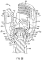
- a bone fixation assembly 20 includes one or more bone fixation elements 22, and four bone fixation elements 22A-D as illustrated in Fig. 1A .
- each bone fixation element 22 extends vertically along an axial direction A, and generally horizontally along a radial direction R extends perpendicular to the axial direction A.
- the radial direction R includes a longitudinal direction L and a lateral direction LA that extends perpendicular to the longitudinal direction L.
- the directional terms are used herein with reference to the orientation of the bone fixation assembly 20 and its components as illustrated, and that the actual orientation of the bone fixation assembly 20 and its components may change during use.
- the axial direction is illustrated as extending along a vertical direction
- the radial direction is illustrated as extending along a horizontal direction, however the directions that encompass the various directions may differ during use, depending, for instance, on the desired orientation of the bone fixation assembly 20 during use.
- the directional terms are used herein merely for the purposes of clarity and convenience only, in a non-limiting manner.
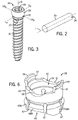
- the bone anchor 30 is configured as a bone screw, or pedicle screw, that includes an externally threaded shaft 31 coupled at its upper end to an enlarged curved head 33.
- the shaft 31 extends axially along a central axis B of rotation, and can define any suitable diameter, length, and thread design so as to engage the underlying bone, such as a vertebra 27.
- the shaft 31 can be unthreaded so as to define a pin or a nail if desired.
- the bone anchor 30 is not limited to any particular type of shaft 31.
- the bone anchor 30 may also be cannulated and fenestrated such that openings extend radially outward from a central hollow channel in a cannulated shaft to urge fluid out of the bone anchor 30 during injection or draw fluid into the central hollow channel from the radial sides of the anchor during extraction of material adjacent the anchor if desired.
- the head 33 can define a semi-spherical curvature, or can alternatively define any suitable curvature as desired to facilitate rotation with respect to the collet 28 as is described in more detail below.
- the head 33 defines a pivot location that extends along a lateral pivot axis of rotation LAp that extends through the head in a direction parallel to the lateral axis LA.
- the head 33 further defines a pivot location that extends along a longitudinal axis of rotation L P that extends through the head in a direction parallel to the longitudinal axis L.
- the head 33 also includes a drive surface 39 configured to receive a corresponding tip of a drive tool, such as a screw driver configured to rotate the bone anchor 30 into engagement with the vertebrae 27 or other underlying bone surface.
- the drive surface 39 can define a hexagon, a star drive pattern, a Phillips head pattern, a slot for a screw driver, threads configured to receive corresponding threads of a threaded drive post, or any suitable drive tool engaging structure as desired.
- a gap G extends circumferentially between adjacent circumferentially outer ends of the arms 42.
- the opposing gaps G are in alignment with the axial bore 54.
- the arms 42 can be disposed radially opposite each other such that the gaps G, in combination with the aligned portion of the axial bore 54, define a rod-receiving channel 36 that is sized and configured to receive the fixation rod 24 such that the fixation rod 24 extends through the bone fixation element 22.
- the gaps G are aligned in the longitudinal direction.
- the fixation rod 24 can thus extend through the opposing gaps G and the axial bore 54.
- the arms 42 define radially inner and outer surfaces 60 and 62, respectively.
- the inner surfaces 60 define threads 62, and are configured to threadedly receive the locking cap 34, as will now be described.
- the saddle 66 can be coupled to the set screw 64 in any desired manner, including adhesion, mechanical fastening, and the like.
- the saddle 66 includes a stem 78 extending centrally upward from the saddle body 72.
- the stem 78 is configured to be received in a central bore 32 extending vertically into the lower end of the set screw body 65, and can be fastened within the central bore with a rivet 80 or other like fastener.
- the saddle 66 is rotatable relative to the set screw 64, such that the saddle 66 can self-align with the fixation rod 24 as the set screw 64 is being rotated with respect to the anchor seat 26, for instance when the locking cap 34 is being tightened against the fixation rod 24.
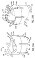
- the support walls 56 each define opposing inner and outer surfaces 86 and 88, respectively.
- the support walls 56 flare inward toward axis A in a downward direction from the arms 42, and terminate at respective lower ends 90.
- the inner surfaces 86 of each support wall 56 at the lower end 90 define a distance D therebetween that is less than the distance between opposing radially opposing inner surfaces 60 of the arms 42, and greater than the diameter of the head 33 of the bone anchor 30.
- the inner surfaces 86 flare radially inward toward the central axis A, and toward each other, along a downward direction, and are each connected to bottommost, and innermost, surfaces that define respective longitudinal guide walls 92.
- each guide wall 92 defines respective inner guide surfaces 93 that extend in a desired plane through which the bone anchor 30 is permitted to pivot relative to the anchor seat 26.
- the desired plane is the sagittal plane SP.
- the anchor seat 26 can be constructed such that the guide walls 92 extend in any desired alternative plane, such as a plane defined by the medial-lateral and anterior-posterior directions.
- the guide walls 92 can be spaced apart a distance greater than the diameter of the neck 35, but disposed within close proximity of the bone anchor 30, so as to limit pivotal movement of the bone anchor 30 relative to the anchor seat 34 in the first direction D in a plane that is perpendicular to the desired (e.g., sagittal plane), for instance about the longitudinal pivot axis L P .
- the bone anchor 30 can pivot about the longitudinal pivot axis L P through a range of angles defined by the central anchor axis B and the central anchor seat axis A that is less than 10°, for instance less than 5°, such as 0°.
- the distance between the opposing guide walls 92 is less than the diameter of the head 33 of the bone anchor 30, while the inner surfaces 86 define a distance therebetween that is slightly greater than the diameter of the anchor head 33.
- the bone anchor can pivot more in the second direction E than in the first direction D.
- the bone anchor 30 can pivot such that the central axis B of the bone anchor can be angularly offset with respect to the central axis A of the anchor seat 26 through a range of angles +/- between 0° and 90° with respect to the vertical, such as between 5° and 45°, including between 15° and 35°, for instance 25° in the sagittal plane before the neck 35 abuts the lower ends 82.
- the neck 35 of the anchor 30 can ride along the guide wall 92 as it pivots in the sagittal plane SP.
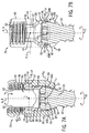
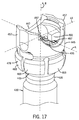
- the collet 28 includes a collet body 45 that defines a first or upper end 47 sized and configured to contact or support at least a portion of the fixation rod 24 when the rod is received within the rod-receiving channel 36, and a second or lower end 49 sized and configured to contact or otherwise engage, directly or indirectly, a portion of the bone anchor head 33.
- the collet body 45 is annular, and thus defines an axial bore 53 extending between and through the upper and lower ends 47 and 49. The axial bore 53 is aligned with the axial bore 54 when the collet 28 is installed in the anchor seat 26.
- the upper end 47 defines radially opposing upwardly facing seat portions 51 having a curvature or semi-spherical shape corresponding to the outer surface of the fixation rod 24, and is therefore configured to receive or otherwise support at least a portion (e.g., a lower portion) of the rod 24.
- the lower end 49 defines an inner surface 55 defining a curvature or semi-spherical shape corresponding to the outer surface of the anchor head 33, and is therefore configured to receive or otherwise engage at least a portion of the head 33, so that the head can rotate with respect to the collet 28 and the anchor seat 26, and can further pivot with respect to the collet 28 as permitted by the anchor seat 26.
- the collet 28 further includes a pair of flanges 57 extending up from the upper end 47 of the collet body 45 at a location radially between the seat portions 51.
- a locking lip 59 extends radially out from each flange 57.
- the anchor seat 26 defines a pair of opposing recesses 61 formed radially in the opposing inner surfaces 86 of the support walls 56 at a location below the threaded inner surfaces 60 of the arms 42.
- the collet 28 can be inserted down into the anchor seat 26, thereby causing the flanges 57 to flex inwardly past the threaded inner surfaces 60, until the lips 59 clear the upper ends 63 of the recesses 61, at which point the flanges 57 snap back out so that the lips 59 are disposed in the recesses 61. Interference between the lips 59 and the upper ends 63 prevent the collet 28 from backing out through the upper end of the anchor scat 26.
- the recesses 61 further define a circumferential length substantially equal to that of the flanges 57 and locking lips 59, such that the collet 28 is rotationally fixed with respect to the anchor seat 26 in a position whereby the upper surface 47 is aligned with the fixation rod 24 when the fixation rod 24 is inserted into the anchor seat 26.
- the lower end 49 of the collet 28 defines an outer diameter that is greater than the inner distance between the guide walls 92. Accordingly, the collet 28 is unable to pass axially down through the lower end of the anchor body 26.
- the lower end 49 includes one or more slots 67 (illustrated as a plurality of slots) extending radially therethrough so as to define opposing pluralities of fingers 69A and 69B.
- the fingers 69A and 69B when the collet 28 and anchor 30 are installed in the anchor seat 24, the fingers 69A and 69B radially expand to conform with the outer surface of the anchor head 33 and the inner surfaces of the support walls 56 and spacer walls 58, respectively, as illustrated in Figs. 7A-B .
- the inner diameters defined by the opposing fingers 69A and 69B are less than the outer diameter of the anchor head 33 to prevent the anchor 30 from being removed from the anchor seat 26 in an axially downward direction.
- the lower ends of the fingers 69A terminate at a location above the guide walls 92, and the lower ends of the fingers 69B terminate at a location above the lower ends 82. Accordingly, the fingers 69A and 69B do not interfere with the engagement between the anchor neck 35 and the guide walls 92 and lower ends 82, and thus do not interfere with the permissible movement of the bone anchors 30 relative to the anchor seat 26.
- one or both of the pluralities of fingers 69A-B could extend below the anchor seat 26, and thus abut the anchor 30 in the manner described above with respect to the guide 92 and stop surface 82 so as to direct movement of the bone anchor 30 in a desired direction (e.g., pivot in the sagittal plane).
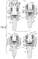
- a method for assembling a bone fixation subassembly 75 includes at step 1, inserting the bone anchor 30 vertically down through the axial bore 54, such that the shaft 31 extends through the lower opening 52 of the lower end 50 of the anchor scat 26.
- the collet 28 is inserted into the axial bore 54 to a location whereby the locking lips 59 can engage the lowermost threads 62 of the inner surface 60 of the arms 42.
- an upward force can be applied to the bone anchor 30 so as to insert the anchor head 33 into the lower end 49 of the collet 28.
- the locking lips 59 of the collet 28 brace against the anchor seat 26 inside the threads 62 to prevent the upward force applied by the screw 28 from causing the collet 28 to back out of the upper opening of the anchor seat 26.
- a downward force is applied to the collet 28, thereby inserting the locking lips 59 into the recesses 61 in the manner described above, and locking the anchor 30 and collet 28 in the anchor seat 26.
- the subassembly 75 can include the collet 28 installed in the anchor seat 26, and the bone anchor 30 installed in the collet 28.
- a subassembly can be provided include the collet installed in the anchor seat without a bone anchor installed in the collet.
- the bone anchor can be implanted into underlying bone before the anchor head is inserted into the collet.
- the anchor 30 can comprise a pin or nail, or a screw as desired.
- bone fixation subassembly 75 and the alternative bone fixation subassemblies described herein can likewise be referred to as spine fixation subassemblies when, for instance, they are configured for implantation into one or more vertebrae for vertebral fixation.
- a driving tool can engage the drive surface 39 of the head 33 so as to insert the threaded shaft 31 into the underlying bone, as shown in Fig. 1A .
- the anchor seat 26 can be rotated about axis A in the direction of Arrow R about the full 360° range of angles so as to align the rod-receiving channel 36 with the longitudinal axis of the fixation rod 24.
- the fixation rod 24 can be inserted into the subassembly 75.
- the fixation rod 24 is inserted into the axial bore 54 either horizontally through the gaps G, or vertically down into the axial bore 54. It should be appreciated that the fixation rod 24 will be seated in the upper end 47 of the collet 28.
- the locking cap 34 can be attached to the subassembly 75 so as to fully assembly the anchor assembly 22.
- the subassembly 75 can further include the fixation rod 24 and/or the locking cap 34.
- the external threads 68 of the set screw 64 are rotated within the inner threads 62 of the anchor seat arms 42, thereby causing the set screw and saddle 66 to move axially down in the axial bore 54.
- the saddle 66 is rotated with respect to the set screw 64 so as to bring the rod-contacting surface 76 into alignment with the fixation rod 24.
- the set screw 64 is continuously threadedly inserted into the bone anchor 26, such that the locking cap 34 can be tightened against the rod 24, thereby applying a downward axial force to the rod 24.
- the locking cap 34 can be said to be in an initial position when installed in the locking cap 34 but before applying an axial force against the fixation rod 24.
- the axial force applied to the rod 24 by the locking cap 34 is transmitted to the collet 28, which causes the fingers 69A to ride along the inner surfaces 86 of the support wall 56, and fingers 69B to ride along the radially inner surfaces of the spacer walls 58.
- the locking cap 34 is configured to transmit a locking force onto the collet 28 and bone anchor 30 to fix or lock the position of the bone anchor 30 relative to the anchor scat 26 and fixation rod 24. Furthermore, when the locking cap 34 is in the locked position, the fixation rod 24 is captured between the saddle 66 and the upper surface of the collet 28 such that the anchor seat 26 is prevented from movement relative to the fixation rod 24.
- the locking cap 34 can be tightened against the rod to an intermediate position that sufficiently radially compresses the fingers 69A-B against the bone anchor 30 that prevents the bone anchor 30 from freely pivoting in the sagittal plane, for instance under gravitational forces, while allowing a surgeon to pivotally adjust the angular position of the bone anchor 30 in from an initial position in a desired plane to a desired position in the desired plane by applying a force to the bone anchor 30 that overcomes the friction between the bone anchor 30 and the fingers 69A-B.
- the desired plane is the sagittal plane
- the locking cap 34 can be further tightened to a locked position whereby the bone anchor 30 is locked in place in the desired angular position in the desired plane. It should be appreciated that the end cap 34 can be unthreaded from the locked position into the intermediate position or the initial position if it is desired to further adjust the angular position of the bone anchor 30.
- the above-described method steps can be performed for each bone fixation element of the bone fixation assembly 20 as desired. Furthermore, the method steps described above need not be performed in the order described, and it should be appreciated that that one or more of the steps can be omitted if desired. It should be further appreciated that while the guide walls 92 prevent the bone anchor 30 from pivoting in a first plane that intersects the sagittal plane relative to the anchor seat 26 and fixation rod 24, the guide walls 92 could alternatively be slightly spaced with respect to the neck 35, such that the anchor 30 can pivot about a first plane that intersects the second sagittal plane within an angular range that is less than the angular range that the anchor 30 can pivot in the sagittal plane.
- one or more bone fixation assemblies 20 can be provided as one or more bone fixation elements 22 provided as a bone fixation kit.
- the kit can include at least one of the following components: one or more bone anchors 30, one or more locking caps 34, one or more collets 28, one or more fixation rods 24, one or more anchor seats 26, and/or one or more preassembled bone fixation subassemblies 75, including a bone anchor 30 and collet 28 pre-installed in the anchor seat 26 in the manner described above.
- the surgeon can implant the bone anchor 30 of a plurality of subassemblies in an underlying bone, such as a vertebra, and the anchor seats of the subassemblies can be coupled to a fixation rod 24 in the manner described above.
- the components included in the kit may vary by at least one characteristic.
- the components included in the kit can vary in size and shape, and/or they can be constructed in accordance with alternative embodiments as described herein, or they could be identically constructed with the same size and shape.
- fixation rods 24 and bone anchors 30 can be provided having different diameters and lengths, and the bone anchors 30 can be provided as screws and nails or pins.
- several kits can be provided, each individual kit including components corresponding to a particular size, and shape, and embodiment, wherein the size, shape, and/or embodiment of the components of the kits can vary from kit to kit.
- a bone fixation subassembly 175 constructed in accordance with an alternative embodiment is illustrated including reference numerals corresponding to like elements of the bone fixation subassembly 75 incremented by 100.
- the bone fixation subassembly 175 can be constructed as described with respect to the bone fixation subassembly 75 except as otherwise noted.
- one or more up to all of the bone fixation elements of the bone fixation assembly 20 can include the bone fixation elements 22 or alternative bone fixation elements as described herein, one or more of which can include the bone fixation subassembly 75, the bone fixation subassembly 175, or any alternative bone fixation subassembly as described herein.
- the bone fixation subassembly 175 includes an anchor seat 126, and a collet 128 preinstalled in the anchor seat 126.
- the subassembly 175 can further include a bone anchor 30 preinstalled in the collet 128, which in turn is preinstalled in the anchor seat 126.
- the subassembly 175 can include the collet 128 preinstalled in the anchor seat 126, and the bone anchor 30 can be later installed as desired.
- the arms 142 extend up from respective support walls 156, and the opposing spacer walls 158 are connected between the support walls 156.
- the arms 142 define internal threads 162 that are configured to engage the external threads 68 of the locking cap 34 as described above.
- the arms 142 further define gaps G therebetween that are configured to receive the fixation rod 24 as described above.
- the support walls 156 flare radially inward toward axis A in a downward direction from the arms 142 toward the lower end 150.
- the lower ends 150 in combination with the collet 128, limit pivotal movement of the bone anchor 30 to a single plane, such as the sagittal plane, as described above.
- the bone anchor 30 can also rotate about its central axial axis B relative to the collet 128 and anchor seat 126 in the manner described above.
- the collet 128 includes a collet body 145 that defines a first or upper end 147 sized and configured to contact or support at least a portion of the fixation rod 24 when the rod is received within the rod-receiving channel 136, and a second or lower end 149 sized and configured to contact or otherwise engage, directly or indirectly, a portion of the bone anchor head 33.
- the upper and lower ends 147 and 149 are constructed as described above, except the collet body 145 includes a finger extension 173 defining the bottom end of each of the fingers 169A.
- the bone fixation subassembly 175 is constructed by inserting the collet 128 down through the top of the anchor seat 126 until the locking lips 59 extend in the corresponding recesses 161.
- the fingers 169A and extensions 173, along with the fingers 169B, are placed over the head 33 of the bone anchor 30, and a downward force is applied until the fingers 169A-B and extensions 173 expand radially outward to capture the head 33 of the bone anchor 30 therein.
- the threaded shaft 31 of the bone anchor 30 may already be implanted into bone prior to popping the collet 128 over the head 33 of the bone anchor 30. It should be appreciated that the diameter of the anchor shaft 31 is not limited by the diameter of the opening 152 of the base 140.
- the radially inner ends of the lower ends of the finger extensions 173 define guide walls 192 that are spaced apart a distance substantially equal to the cross-sectional dimension of the anchor neck 35.
- the guide walls 192 therefore abut the neck 35 when the head 33 is captured in the collet 128. Accordingly, the guide walls 192 permit the anchor 33 to pivot only in a desired plane that is parallel to the guide walls 192, or about the lateral pivot axis LA P (e.g., the sagittal plane).
- the permitted angulation in the sagittal plane is limited by contact between the neck 35 and the lower ends of the spacer walls 158 in the manner described above with respect to the bone fixation element 22.
- a bone fixation subassembly 275 constructed in accordance with an alternative embodiment is illustrated including reference numerals corresponding to like elements of the bone fixation subassembly 75 incremented by 200.
- the bone fixation subassembly 275 can be constructed as described above with respect to one or both of the bone fixation subassemblies except as otherwise described. It should be appreciated that one or more up to all of the bone fixation elements of the bone fixation assembly 20 can include the bone fixation elements 22 or alternative bone fixation elements as described herein, one or more of which can include the bone fixation subassembly 275 as will now be described.
- the anchor seat body 238 includes a recess 285 extending in the support walls 256 and one of the spacer walls 258 sized to receive the anchor seat extension 277.
- the recess 285 is keyed to receive the posts 281 in the support walls 256, such that the circumferential collar extends along one longitudinal end of the collar body but not the other longitudinal end.
- the outer diameter of the anchor seat extension 277 is substantially equal to the outer diameter of the lower end 250 of the anchor seat body 238, such that the outer circumferential surface of the extension 277 is flush with the outer circumferential surface of the anchor seat body 238 when the extension 277 is disposed in the recess 285.
- the outer diameter defined by the tabs 283 is substantially equal to the inner diameter of the support walls 256.
- the collar 279 can be disposed at the inferior end of the anchor seat 226 when the bone fixation element is implanted, such that the anchor 230 can pivot along a greater angular range toward the superior end in the sagittal plane than toward the inferior end.
- the collar 279 can be disposed at the superior end of the anchor seat 226 when the bone fixation element is implanted, such that the anchor 230 can pivot along a greater angular range toward the superior end in the sagittal plane than toward the inferior end.
- the locking cap 34 can be locked in the subassembly 275 in the manner described above.
- a bone fixation subassembly 375 constructed in accordance with an alternative embodiment is illustrated including reference numerals corresponding to like elements of the bone fixation subassembly 75 incremented by 300.
- the bone fixation subassembly 375 can be constructed as described with respect to one or all of the bone fixation subassemblies described above, except as otherwise noted. It should be appreciated that one or more up to all of the bone fixation elements of the bone fixation assembly 20 can include the bone fixation elements 22 or alternative bone fixation elements as described herein, one or more of which can include the bone fixation subassembly 375 as will now be described.
- the bone fixation subassembly 375 includes an anchor seat 326, and a collet 328 preinstalled in the anchor seat 326.
- the subassembly 375 can further include a bone anchor 330 preinstalled in the collet 328, which in turn is preinstalled in the anchor seat 326.
- the subassembly 375 be provided with the collet 328 preinstalled in the anchor seat 326, such that the bone anchor 330 can be later installed as desired.
- the collet 328 includes a collet extension 387 that is separate from the collet body 345.
- the extension 387 is configured to fasten to the bone anchor 330 after the bone anchor 330 has been attached to the collet 328.
- the extension 387 is provided as a clip that can be snapped onto the neck 335 of the bone anchor 330.
- the bone anchor 330 is illustrated as a nail or a pin, it should be appreciated that the anchor 330 could alternatively comprise a screw.
- the collet extension 387 includes a circumferential collar 389 and a pair of opposing posts 391 extending out (or vertically up in the illustrated orientation) from the collar 389.
- the posts 391 also flare radially outward along a vertically upward direction of travel.
- the collar 389 extends circumferentially greater than 180° but less than 360°, defines an inner diameter substantially equal to the inner diameter of the collet body 345, and an outer diameter substantially equal to the outer diameter of the collet body 345
- the subassembly 375 is constructed using a method that begins at step 1) wherein the collet 328 is installed in the anchor seat 326 by inserting the collet 328 vertically upward into the lower opening 352 of the anchor seat body 338, in the manner described above.
- the kit can include the subassembly 375 as including the anchor seat 326 and the installed collet 328.
- the anchor body 338 is brought down onto the anchor head 333 (or the anchor head 333 is brought up into the anchor body 338), thereby causing the collet fingers 169A-B to expand radially over the head 333 and snap down over the head 333 to secure the anchor therein.
- Fig. 16 illustrates the subassembly as including the anchor seat 326 and the collet 328 installed in the anchor seat 326, the collet extension 387 clipped onto the bone anchor 330, and the bone anchor 330 and collet extension 387 attached to the anchor seat 326 and collet 328.
- the subassembly 375 can include the anchor seat and the collet 328 without the anchor 330 and extension 387 installed.
- the anchor 330 can be implanted into the underlying bone (e.g., vertebra) before or after the collet extension 387 is clipped onto the neck, and prior to or after the anchor 330 is attached to the collet 328.
- the anchor 330 is freely rotatable within the collet 328 and extension 387 with respect to the anchor seat 326.
- the bottom surface of the posts 381 abut the neck 333, and therefore provide a laterally extending guide 392 that allows the anchor 330 to pivot in the sagittal plane, while preventing the anchor 330 from pivoting in any other angle that intersects the sagittal plane.
- the extension 377 does not extend entirely around the anchor neck 335, and thus defines a gap that is disposed on one longitudinal side of the anchor 330.
- the anchor 330 is free to pivot toward that longitudinal side in the sagittal plane until the anchor 330 abuts the lower end of the respective spacer wall 338, which provides a stop for the anchor 330 in the sagittal plane.
- the collar 379 extends along the opposing longitudinal side of the anchor 330, and can be vertically flush with or above the bottom surface of the corresponding spacer wall 338 such that the spacer wall provides a stop with respect to angular movement of the anchor 330 in the sagittal plane.
- the collar 379 could be disposed below the bottom surface of the corresponding spacer wall 338 such that the collar 379 provides a stop with respect to angular movement of the anchor 330 in the sagittal plane.
- the collar 379 can limit pivotal movement in one direction in the pivotal plane.
- the radially inner surface of the collar 379 could be radially outwardly displaced with respect to the radial inner surface of the posts 381, such that the collar 379 does not abut the neck 335 and thus permits pivotal movement in the sagittal plane toward the collar 379.
- the collar 379 can be disposed at the inferior end of the anchor seat 326 when the bone fixation element is implanted, such that the anchor 330 can pivot along a greater angular range toward the superior end in the sagittal plane than toward the inferior end.
- the collar 379 can be disposed at the superior end of the anchor seat 326 when the bone fixation element is implanted, such that the anchor 330 can pivot along a greater angular range toward the superior end in the sagittal plane than toward the inferior end.
- the locking cap 34 can be locked in the subassembly 375 in the manner described above.
- a bone fixation subassembly 475 constructed in accordance with an alternative embodiment is illustrated including reference numerals corresponding to like elements of the bone fixation subassembly 75 incremented by 400.
- the bone fixation subassembly 475 can be constructed as described with respect to one or all of the bone fixation subassemblies, except as otherwise noted.
- one or more up to all of the bone fixation elements of the bone fixation assembly 20 can include the bone fixation elements 22 or alternative bone fixation elements as described herein, one or more of which can include the bone fixation subassembly 475 as will now be described.
- the bone fixation subassembly 475 includes an anchor seat 426, and a collet 428 preinstalled in the anchor seat 426.
- the subassembly 475 can further include a bone anchor 430 that can be preinstalled in the collet 428 as part of the subassembly 475 provide in the kit, or the bone anchor 430 can be provided separately, and later installed in the subassembly 475, for instance before or after being implanted in an underlying bone.
- the anchor can comprise a pin or nail, or a screw as desired.
- the anchor seat 426 includes an anchor seat body 438 extending centrally along the central axis A.
- the body 438 includes a base 440 and a pair of spaced opposing arms 442 extending up from the base 440.
- the base 440 defines a lower end 450 that is also the lower end of the body 438, and defines a lower opening 452.
- the body 438 defines an axial bore 454 extending from the lower opening 452 to the upper opening 448.
- the arms 442 extend up from respective support walls 456, and the opposing spacer walls 458 are connected between the support walls 456.
- the arms 442 define gaps G therebetween that are configured to receive the fixation rod 24 as described above.
- the arms 442 further define internal threads 462 that are configured to engage the external threads 68 of the locking cap 34 as described above.
- the collet 428 includes a collet body 445 that defines a first or upper end 447 sized and configured to contact or support at least a portion of the fixation rod 24 when the rod is received within the rod-receiving channel 436, and a second or lower end 449 sized and configured to contact or otherwise engage, directly or indirectly, a portion of the bone anchor head 33.
- the upper and lower ends 447 and 449 are generally constructed as described above, with respect to the collet 28, except the collet body includes fingers 469 of the same vertical length. Of course, it should be appreciated that one or more of the fingers 469 can extend down a greater or lesser difference than one or more of the other fingers.
- the collet 428 further includes a pair of radially opposing protrusions 493 projecting radially inward from the upper ends of the collet flanges 457.
- the flanges 457 are located in the recesses 461 such that the protrusion 493 is disposed radially centrally with respect to the arms 442 when the collet 428 is installed in the anchor seat.
- Each protrusion 493 defines a lower vertex 495 and upwardly angled walls 497 extending longitudinally out from the vertex 495.
- the protrusion 493 permits the anchor 430 to pivot in a desired plane (e.g., the sagittal plane) relative to the collet 428 and anchor seat 426, while interference between the vertex 495 and the anchor head 433 prevents the anchor 430 from pivoting in any plane that intersects the sagittal plane.
- the anchor 430 can pivot in the desired plane through an angular range defined by the axis A and pivoted axes of rotation B' of the bone anchor 430.
- the protrusions 493 provide a guide that permits the anchor 430 to pivot in the desired plane while preventing pivotal movement of the bone anchor in all other planes that intersect the sagittal plane.
- the anchor 430 can freely rotate about its axis B with respect to the collet 428 and the anchor 426 in the manner described above.
- the bone fixation subassembly 475 is constructed by inserting the collet 428 down through the top of the anchor seat 426 until the flanges 457 are locked in the corresponding recesses 461.
- the fingers 469A are placed over the head 33 of the bone anchor 30, and a downward force is applied against the anchor 430 until the fingers 169 expand radially outward to capture the head 433 of the bone anchor 430 therein.
- the threaded shaft 431 of the bone anchor 430 may already be implanted into bone prior to popping the collet 428 over the anchor head 433.
- the locking cap 34 can be locked in the subassembly 475 in the manner described above.
- a bone fixation subassembly 575 constructed in accordance with an alternative embodiment is illustrated including reference numerals corresponding to like elements of the bone fixation subassembly 75 incremented by 500.
- the bone fixation subassembly 575 can be constructed as described above with respect to one or all of the bone fixation subassemblies, except as otherwise noted. It should be appreciated that one or more up to all of the bone fixation elements of the bone fixation assembly 20 can include the bone fixation elements 22 or alternative bone fixation elements as described herein, one or more of which can include the bone fixation subassembly 575 as will now be described.
- the bone fixation subassembly 575 includes an anchor seat 526, and a collet 528 preinstalled in the anchor seat 526.
- the subassembly 575 can further include a bone anchor 530 that can be preinstalled in the collet 528 as part of the subassembly 575 provide in the kit, or the bone anchor 530 can be provided separately, and later installed in the subassembly 575, for instance before or after being implanted in an underlying bone.
- the anchor 530 is illustrated as a pin or nail, though the anchor 530 could alternatively be constructed as a screw.
- the anchor scat 526 includes an anchor scat body 538 extending centrally along the central axis A.
- the body 538 includes a base 540 and a pair of spaced opposing arms 542 extending up from the base 540.
- the base 540 defines a lower end 550 that is also the lower end of the body 538, and defines a lower opening 552.
- the body 538 defines an axial bore 554 extending from the lower opening 552 to the upper opening 548.
- the arms 542 extend up from respective support walls 556, and the opposing spacer walls 558 are connected between the support walls 556.
- the arms 542 define gaps G therebetween that are configured to receive the fixation rod 24 as described above.
- the arms 542 further define internal threads 562 that are configured to engage the external threads 68 of the locking cap 34 as described above.
- the collet 528 includes a collet body 545 that defines a first or upper end 547 sized and configured to contact or support at least a portion of the fixation rod 24 when the rod is received within the rod-receiving channel 536, and a second or lower end 549 sized and configured to contact or otherwise engage, directly or indirectly, a portion of the bone anchor head 33.
- the upper and lower ends 547 and 549 are generally constructed as described above, with respect to the collet 428, except the collet body defines a U-shaped recess 599 extending radially inward into the radially outer surface of each flange 557.
- the recess 599 is configured to engage mating structure of the anchor seat 226 that prevents the collet 528 from inadvertently backing out of the anchor seat 226 during use.
- the collet 528 further includes an interior threaded surface 601 disposed axially above the protrusion 593, which can receive corresponding threads of an insertion tool when assembling the subassembly 575.
- the protrusion extends radially inward with respect to the protrusion 493, such that it engages the upper surface of a flat ledge 603 extending circumferentially about the anchor head 533.
- the flat ledge 603 defines a pair of opposing abutment surfaces that extend along a lateral axis that extends perpendicular to the longitudinal axis L defined by the opposing gaps G.
- the anchor 530 can therefore pivot in a desired (e.g., sagittal) plane about the protrusion 593 as described above. Additionally, as described above, the bone anchor 530 is free to rotate within the collet 528 relative to the anchor seat 526 as described above.
- the bone fixation subassembly 575 is constructed by inserting the collet 528 down through the top of the anchor seat 526 until the flanges 557 are locked in the corresponding recesses 561.
- the fingers 569 are placed over the head 33 of the bone anchor 30, and a downward force is applied against the anchor 530 until the fingers 169 expand radially outward to capture the head 533 of the bone anchor 530 therein.
- the threaded shaft 531 of the bone anchor 530 may already be implanted into bone prior to popping the collet 528 over the anchor head 533.
- the bone anchor 530 can be installed in the collet 528, and subsequently implanted into underlying bone.
- the internal threading 601 of the collet 528 allows for the use of a special driver instrument having an engagement feature, e.g., a T25 feature, which can mate with the screwdriver to further stabilize the bone anchor 530 as it is implanted into the underlying bone.
- a special driver instrument having an engagement feature, e.g., a T25 feature, which can mate with the screwdriver to further stabilize the bone anchor 530 as it is implanted into the underlying bone.
- the locking cap 34 can be locked in the subassembly 575 in the manner described above.
- a bone fixation subassembly 675 constructed in accordance with an alternative embodiment is illustrated including reference numerals corresponding to like elements of the bone fixation subassembly 75 incremented by 600.
- the bone fixation subassembly 675 can be constructed as described above with respect to one or all of the bone fixation subassemblies, except as otherwise noted.
- one or more up to all of the bone fixation elements of the bone fixation assembly 20 can include the bone fixation elements 22 or alternative bone fixation elements as described herein, one or more of which can include the bone fixation subassembly 675 as will now be described.
- the bone fixation subassembly 675 includes an anchor seat 626, and a collet 628 preinstalled in the anchor seat 626.
- the subassembly 675 can further include a bone anchor 630 that can be preinstalled in the collet 628 as part of the subassembly 675 provide in the kit, or the bone anchor 630 can be provided separately, and later installed in the subassembly 675, for instance before or after being implanted in an underlying bone.
- the anchor 630 is illustrated as a pin or nail, though the anchor 530 could alternatively be constructed as a screw.
- the anchor seat 626 extends centrally along the central axis A, and includes a pair of spaced opposing arms 642 extending up from respective support walls 656.
- the opposing spacer walls 658 are connected between the support walls 656.
- the anchor seat 626 defines a lower end 650 that defines a lower opening 652.
- An axial bore 654 extends from the lower opening 652 to the upper opening 648.
- the arms 642 define gaps G therebetween that are configured to receive the fixation rod 24 as described above.
- the arms 642 further define internal threads 662 that are configured to engage the external threads 68 of the locking cap 34 in the manner described above.
- the collet 628 includes a collet body 645 that defines a first or upper end 647 sized and configured to contact or support at least a portion of the fixation rod 24 when the rod is received within the rod-receiving channel 636, and a second or lower end 649 sized and configured to contact or otherwise engage, directly or indirectly, a portion of the bone anchor head 33.
- the upper and lower ends 647 and 649 are generally constructed as described above, with respect to the collet 528, except each flange 657 includes a pair of opposing vertical ribs 707 spaced apart a distance by a gap 709.
- the outer circumferential edges of the ribs 707 are spaced apart substantially the same distance as the circumferential edges of the recess 661 formed in the inner surface of the support walls 656. As a result, when the collet 628 is inserted into the anchor seat 626, the ribs 707 become disposed in the recess 661.
- the collet 628 further includes an inner threaded surface 701, and protrusions 693 disposed below the threaded surface 701.
- the protrusions 693 define a guide that allows the bone anchor 30 to pivot relative to the anchor seat in the sagittal plane, in the manner described above.
- the bone anchor 630 includes a pair of opposing flat ledges 703 extending circumferentially around the anchor head 633 in the manner described above.
- the remainder of the anchor head 633 can be round in the manner described above.
- the ledges 703 are configured to abut the lower end of the protrusions 693 when the collet 628, anchor 630, and fixation rod 24 are installed in the anchor seat 626, as will now be described with respect to Figs. 24-25 .
- the bone fixation subassembly 675 is constructed by inserting the collet 628 down through the top of the anchor seat 626 to an initial insertion position at step 1, until the flanges 657 are disposed in the corresponding recesses 661 in the manner described above.
- the upper end 647 of the collet can be aligned with the gaps G.
- the bone anchor 630 is inserted into the lower end 652 of the anchor seat 626, thereby popping the fingers 669 over the anchor head 633 so as to attach the anchor 630 to the collet 628.
- the bone anchor 630 can be inserted into the anchor seat 626 and collet 628 when assembling the subassembly 675, or after the subassembly 675 has been assembled, for instance interoperatively (e.g., after the bone anchor 630 has been affixed in a vertebrae).
- the upper ends 647 of the collet 628 are angularly offset with respect to the rod-receiving channel 636.
- the upper ends 647 are oriented perpendicular with respect to the channel 636.
- a downward force is applied on the anchor 630 relative to the anchor seat 626 at step 3, which brings the collet 628 to an intermediate insertion position, whereby the fingers 669 bear against the support walls 656 and spacer walls 658.
- the intermediate insertion position the lower ends of the fingers 669 are aligned with the lower ends of the support walls 656 and spacer walls 658.
- the flanges 657 flare radially inward out of engagement with the recesses 661, and bear against the radially inner surfaces of the support walls 656.
- the flanges 657 of the collet 628 are disposed in the rod-receiving channel 636, and thus positioned to interfere with the fixation rod 24 when the fixation rod is inserted. Because the flanges ledges 703 are not disposed in the recess 661, the collet 628, and thus the bone anchor 633, is unimpeded with respect to pivotal movement about any radial axis about a 360° range with respect to the anchor seat 626, and therefore along any corresponding plane as desired, including the sagittal plane and any other plane angularly offset with respect to the sagittal plane.
- the anchor 630 is further able to freely rotate about its central axis B relative to the collet 628 and the anchor seat 626.
- the collet 628 is rotated in the direction of Arrow A about axis A, until the flanges 657 are brought into alignment with the corresponding recesses 661.
- the anchor scat 626 includes a retention dimple 711 extending radially inward from each support wall 656 at a location circumferentially centrally disposed in the corresponding recess 661.
- the collet 628 is rotated in the direction of Arrow A, one of each pair of ribs 707 cams over the dimple 711. Until each dimple 711 is disposed in the corresponding gap 709. Interference between the dimple 711 and the ribs 707 therefore resists rotation of the collet 628 relative to the anchor seat 626.
- the collet 628 is unable to freely rotate or pivot relative to the anchor seat 626. Because the protrusions 693 are aligned with, and abut, the ledges 703 of the anchor 630, the protrusions 693 provide a guide that prevents pivotal movement of the anchor 630 relative to the anchor seat 626 in all planes other than the sagittal plane as described above.
- the upper ends 647 of the collet 626 are aligned with the rod-receiving channel 636, thereby providing a seat for the fixation rod 24 in the manner described above.
- interference between the dimples 711 and the flanges 707 prevent inadvertent rotation of the collet 628 relative to the anchor seat 626 that would bring the flange out of the recess 661.
- deliberate rotation of the collet 628 about axis A relative to the anchor seat for instance with a tool that engages the internal threads 701, can cause the flange 657 to flex radially inward as the ribs 707 cam over the dimples 71 1. Once the flange 657 flexes inward, the dimple 711 is no longer disposed in the gap 709.
- the flange 657 rotates to a position circumferentially between recesses 661, whereby the collet 628 and bone anchor 630 can freely pivot and rotate relative to the anchor seat 626 as described above.
- a surgical instrument could rotate the collet 628 between its locked position whereby the dimples 711 are disposed in the gaps 709 and its unlocked position whereby the flanges 657 are disposed outside of the recesses 661.
- the bone anchor 630 When the collet 628 is in the unlocked position, the bone anchor 630 is permitted to pivot both in the sagittal plane and in any other plane angularly offset with respect to the sagittal plane about a 360° range. When the collet 628 is in the locked position, the bone anchor 630 is permitted to pivot only in the sagittal plane relative to the anchor seat 626. Once the anchor seat 626 has been aligned with the fixation rod 24, and the position of the bone anchor 630 has been located as desired, the locking cap 34 can be locked in the subassembly 675 in the manner described above.
Priority Applications (2)
| Application Number | Priority Date | Filing Date | Title |
|---|---|---|---|
| EP24152971.8A EP4335395A2 (fr) | 2008-11-03 | 2009-11-03 | Ensemble de fixation osseuse uniplanaire |
| EP20162237.0A EP3682828B1 (fr) | 2008-11-03 | 2009-11-03 | Ensemble de fixation d'os uniplanaire |
Applications Claiming Priority (3)
| Application Number | Priority Date | Filing Date | Title |
|---|---|---|---|
| US11070408P | 2008-11-03 | 2008-11-03 | |
| EP09745263.5A EP2376005B1 (fr) | 2008-11-03 | 2009-11-03 | Ensemble fixation osseuse plane |
| PCT/US2009/063056 WO2010062736A1 (fr) | 2008-11-03 | 2009-11-03 | Ensemble fixation osseuse plane |
Related Parent Applications (2)
| Application Number | Title | Priority Date | Filing Date |
|---|---|---|---|
| EP09745263.5A Division EP2376005B1 (fr) | 2008-11-03 | 2009-11-03 | Ensemble fixation osseuse plane |
| EP09745263.5A Division-Into EP2376005B1 (fr) | 2008-11-03 | 2009-11-03 | Ensemble fixation osseuse plane |
Related Child Applications (2)
| Application Number | Title | Priority Date | Filing Date |
|---|---|---|---|
| EP24152971.8A Division EP4335395A2 (fr) | 2008-11-03 | 2009-11-03 | Ensemble de fixation osseuse uniplanaire |
| EP20162237.0A Division EP3682828B1 (fr) | 2008-11-03 | 2009-11-03 | Ensemble de fixation d'os uniplanaire |
Publications (2)
| Publication Number | Publication Date |
|---|---|
| EP3117788A1 true EP3117788A1 (fr) | 2017-01-18 |
| EP3117788B1 EP3117788B1 (fr) | 2020-04-01 |
Family
ID=41503738
Family Applications (4)
| Application Number | Title | Priority Date | Filing Date |
|---|---|---|---|
| EP20162237.0A Active EP3682828B1 (fr) | 2008-11-03 | 2009-11-03 | Ensemble de fixation d'os uniplanaire |
| EP16162864.9A Active EP3117788B1 (fr) | 2008-11-03 | 2009-11-03 | Ensemble fixation osseuse plane |
| EP09745263.5A Active EP2376005B1 (fr) | 2008-11-03 | 2009-11-03 | Ensemble fixation osseuse plane |
| EP24152971.8A Pending EP4335395A2 (fr) | 2008-11-03 | 2009-11-03 | Ensemble de fixation osseuse uniplanaire |
Family Applications Before (1)
| Application Number | Title | Priority Date | Filing Date |
|---|---|---|---|
| EP20162237.0A Active EP3682828B1 (fr) | 2008-11-03 | 2009-11-03 | Ensemble de fixation d'os uniplanaire |
Family Applications After (2)
| Application Number | Title | Priority Date | Filing Date |
|---|---|---|---|
| EP09745263.5A Active EP2376005B1 (fr) | 2008-11-03 | 2009-11-03 | Ensemble fixation osseuse plane |
| EP24152971.8A Pending EP4335395A2 (fr) | 2008-11-03 | 2009-11-03 | Ensemble de fixation osseuse uniplanaire |
Country Status (8)
| Country | Link |
|---|---|
| US (5) | US8628558B2 (fr) |
| EP (4) | EP3682828B1 (fr) |
| JP (1) | JP2012508038A (fr) |
| KR (1) | KR20110081875A (fr) |
| CN (1) | CN102202589A (fr) |
| BR (1) | BRPI0920181A2 (fr) |
| CA (1) | CA2742399A1 (fr) |
| WO (1) | WO2010062736A1 (fr) |
Families Citing this family (89)
| Publication number | Priority date | Publication date | Assignee | Title |
|---|---|---|---|---|
| US6716214B1 (en) | 2003-06-18 | 2004-04-06 | Roger P. Jackson | Polyaxial bone screw with spline capture connection |
| US8444681B2 (en) | 2009-06-15 | 2013-05-21 | Roger P. Jackson | Polyaxial bone anchor with pop-on shank, friction fit retainer and winged insert |
| US9393047B2 (en) | 2009-06-15 | 2016-07-19 | Roger P. Jackson | Polyaxial bone anchor with pop-on shank and friction fit retainer with low profile edge lock |
| US9980753B2 (en) | 2009-06-15 | 2018-05-29 | Roger P Jackson | pivotal anchor with snap-in-place insert having rotation blocking extensions |
| US8100946B2 (en) | 2005-11-21 | 2012-01-24 | Synthes Usa, Llc | Polyaxial bone anchors with increased angulation |
| EP2117451A1 (fr) * | 2006-12-29 | 2009-11-18 | Zimmer Spine Austin, Inc. | Systèmes et procédés de stabilisation de la colonne vertébrale |
| US8636783B2 (en) * | 2006-12-29 | 2014-01-28 | Zimmer Spine, Inc. | Spinal stabilization systems and methods |
| DE602008004916D1 (de) * | 2007-07-20 | 2011-03-24 | Synthes Gmbh | Mehrachsiges Knochenfixierungselement |
| US9439681B2 (en) | 2007-07-20 | 2016-09-13 | DePuy Synthes Products, Inc. | Polyaxial bone fixation element |
| EP2211742A4 (fr) | 2007-10-24 | 2012-12-19 | Nuvasive Inc | Système de fixation chirugicale et procédés associés |
| US9060813B1 (en) | 2008-02-29 | 2015-06-23 | Nuvasive, Inc. | Surgical fixation system and related methods |
| JP2012529969A (ja) | 2008-08-01 | 2012-11-29 | ロジャー・ピー・ジャクソン | スリーブ付き張力付与りコードを備える長手方向接続部材 |
| WO2010028287A2 (fr) | 2008-09-05 | 2010-03-11 | Synthes Usa, Llc | Ensemble fixation osseuse |
| US9241739B2 (en) | 2008-09-12 | 2016-01-26 | DePuy Synthes Products, Inc. | Spinal stabilizing and guiding fixation system |
| EP2339975B1 (fr) | 2008-09-29 | 2015-03-25 | Synthes GmbH | Vis polyaxiale à chargement par le bas et ensemble tige |
| WO2010062736A1 (fr) | 2008-11-03 | 2010-06-03 | Synthes Usa, Llc | Ensemble fixation osseuse plane |
| EP2221013B1 (fr) | 2009-02-20 | 2015-08-05 | Biedermann Technologies GmbH & Co. KG | Pièce de réception pour recevoir une tige pour coupler la tige sur un élément d'ancrage d'os et dispositif d'ancrage d'os avec une telle pièce de réception |
| WO2010120989A1 (fr) | 2009-04-15 | 2010-10-21 | Synthes Usa, Llc | Connecteur de révision pour constructions rachidiennes |
| US11229457B2 (en) * | 2009-06-15 | 2022-01-25 | Roger P. Jackson | Pivotal bone anchor assembly with insert tool deployment |
| US11464549B2 (en) | 2009-06-15 | 2022-10-11 | Roger P. Jackson | Pivotal bone anchor assembly with horizontal tool engagement grooves and insert with upright arms having flared outer portions |
| EP2757988A4 (fr) | 2009-06-15 | 2015-08-19 | Jackson Roger P | Dispositif d'ancrage osseux polyaxial doté d'une tige à enclenchement par pression et insert à ailettes à pince de compression à ajustement par friction |
| US8998959B2 (en) * | 2009-06-15 | 2015-04-07 | Roger P Jackson | Polyaxial bone anchors with pop-on shank, fully constrained friction fit retainer and lock and release insert |
| JP5654584B2 (ja) | 2009-06-17 | 2015-01-14 | ジンテス ゲゼルシャフト ミット ベシュレンクテル ハフツング | 脊柱構築用の修正コネクタ |
| EP2609883B1 (fr) * | 2009-08-12 | 2016-11-02 | Biedermann Technologies GmbH & Co. KG | Pièce de réception pour recevoir une tige pour coupler la tige sur un élément d'ancrage d'os |
| EP2727546A3 (fr) | 2009-08-20 | 2014-07-30 | Biedermann Technologies GmbH & Co. KG | Dispositif d'ancrage d'os, outil et procédé d'assemblage de celui-ci et outil destiné à être utilisé avec celui-ci. |
| AU2010303934B2 (en) | 2009-10-05 | 2014-03-27 | Roger P. Jackson | Polyaxial bone anchor with non-pivotable retainer and pop-on shank, some with friction fit |
| EP2335625B1 (fr) * | 2009-12-21 | 2014-10-22 | Biedermann Technologies GmbH & Co. KG | Dispositif d'ancrage d'os |
| US8740945B2 (en) * | 2010-04-07 | 2014-06-03 | Zimmer Spine, Inc. | Dynamic stabilization system using polyaxial screws |
| US10603083B1 (en) | 2010-07-09 | 2020-03-31 | Theken Spine, Llc | Apparatus and method for limiting a range of angular positions of a screw |
| US9084634B1 (en) | 2010-07-09 | 2015-07-21 | Theken Spine, Llc | Uniplanar screw |
| EP2611373B1 (fr) | 2010-08-30 | 2015-11-04 | Zimmer Spine, Inc. | Vis pédiculaire polyaxiale |
| GB2502449A (en) | 2010-11-02 | 2013-11-27 | Roger P Jackson | Polyaxial bone anchor with pop-on shank and pivotable retainer |
| US9044274B2 (en) * | 2010-12-01 | 2015-06-02 | Amendia, Inc. | Bone screw system |
| EP2460484A1 (fr) * | 2010-12-01 | 2012-06-06 | FACET-LINK Inc. | Agencement de fixation de vis d'os à angle variable |
| ES2436067T3 (es) * | 2010-12-13 | 2013-12-26 | Biedermann Technologies Gmbh & Co. Kg | Dispositivo de anclaje para huesos |
| ES2614270T3 (es) * | 2010-12-27 | 2017-05-30 | Biedermann Technologies Gmbh & Co. Kg | Dispositivo de anclaje óseo poliaxial |
| US9387013B1 (en) | 2011-03-01 | 2016-07-12 | Nuvasive, Inc. | Posterior cervical fixation system |
| US8337530B2 (en) * | 2011-03-09 | 2012-12-25 | Zimmer Spine, Inc. | Polyaxial pedicle screw with increased angulation |
| WO2012128825A1 (fr) * | 2011-03-24 | 2012-09-27 | Jackson Roger P | Ancrage osseux polyaxial avec articulation composée et tige enclipsable |
| US9603630B2 (en) * | 2011-04-29 | 2017-03-28 | Warsaw Orthopedic, Inc. | Rotatable base multi-axial screw assembly |
| US9993269B2 (en) * | 2011-07-15 | 2018-06-12 | Globus Medical, Inc. | Orthopedic fixation devices and methods of installation thereof |
| EP2586392B1 (fr) | 2011-10-27 | 2015-06-24 | Biedermann Technologies GmbH & Co. KG | Dispositif d'ancrage d'os polyaxial à angulation élevée |
| EP2606841B1 (fr) * | 2011-12-23 | 2016-03-09 | Biedermann Technologies GmbH & Co. KG | Dispositif polyaxial d'ancrage osseux |
| US8911479B2 (en) | 2012-01-10 | 2014-12-16 | Roger P. Jackson | Multi-start closures for open implants |
| KR101199458B1 (ko) * | 2012-02-17 | 2012-11-09 | 고려대학교 산학협력단 | 척추 고정용 장치 |
| ES2527766T3 (es) * | 2012-05-29 | 2015-01-29 | Biedermann Technologies Gmbh & Co. Kg | Pieza receptora para recibir y alojar una barra con el fin de acoplarla con un elemento de anclaje de hueso, y dispositivo de anclaje de hueso con una pieza receptora de este tipo |
| AU2013271549A1 (en) * | 2012-06-06 | 2015-01-22 | Medivest, Llc | Expandable tissue spacer implant and method of use |
| ES2539388T3 (es) | 2012-07-18 | 2015-06-30 | Biedermann Technologies Gmbh & Co. Kg | Dispositivo de anclaje óseo poliaxial |
| US9572598B2 (en) | 2012-08-09 | 2017-02-21 | Spine Craft, LLC | Uniplanar surgical screw assembly |
| US9179957B2 (en) | 2012-08-09 | 2015-11-10 | Spinecraft, LLC | Systems, assemblies and methods for spinal derotation |
| US9579125B2 (en) * | 2013-02-09 | 2017-02-28 | Vertiscrew, Llc | Bone screw |
| EP2764840B1 (fr) | 2013-02-11 | 2017-05-03 | Biedermann Technologies GmbH & Co. KG | Ensemble de couplage d'une tige à un élément d'ancrage osseux et dispositif d'ancrage osseux avec un tel ensemble de couplage |
| US9649134B2 (en) * | 2013-04-12 | 2017-05-16 | Alphatec Spine, Inc. | Uniplanar screw assembly and methods of use |
| US20150073488A1 (en) * | 2013-09-09 | 2015-03-12 | James A. Rinner | Spinal stabilization system |
| EP2851021B1 (fr) * | 2013-09-19 | 2016-12-14 | Biedermann Technologies GmbH & Co. KG | Ensemble de couplage d'une tige à un élément d'ancrage osseux, dispositif d'ancrage osseux polyaxial et dispositif de stabilisation modulaire |
| JP5799066B2 (ja) * | 2013-09-27 | 2015-10-21 | 株式会社ロバート・リード商会 | 脊椎固定装置及び脊椎固定システム |
| CN105848597A (zh) * | 2013-11-22 | 2016-08-10 | 脊柱平衡股份有限公司 | 多轴向椎弓根螺钉组件及用于该螺钉组件的封装 |
| US10918419B2 (en) * | 2014-04-01 | 2021-02-16 | K2M, Inc. | Spinal fixation device |
| EP2932929B1 (fr) * | 2014-04-15 | 2017-02-08 | Biedermann Technologies GmbH & Co. KG | Élément de vis destiné à être utilisé dans la colonne vertébrale, en chirurgie des accidents ou orthopédique, système d'un tel élément de vis et tournevis adapté à celui-ci |
| US10543021B2 (en) * | 2014-10-21 | 2020-01-28 | Roger P. Jackson | Pivotal bone anchor assembly having an open ring positioner for a retainer |
| US11219471B2 (en) | 2014-10-21 | 2022-01-11 | Roger P. Jackson | Pivotal bone anchor receiver having an insert with post-placement tool deployment |
| WO2016077606A1 (fr) | 2014-11-12 | 2016-05-19 | Medivest, Llc | Implant d'espacement vertébral, ensemble d'espacement vertébral, dispositif d'expansion et instrument de mise en place, nécessaire et procédés d'assemblage et d'utilisation |
| EP3023064B1 (fr) | 2014-11-20 | 2019-01-09 | Biedermann Technologies GmbH & Co. KG | Partie réceptrice d'accouplement d'un ancrage osseux à une tige et dispositif d'ancrage osseux avec une telle pièce |
| US9717541B2 (en) * | 2015-04-13 | 2017-08-01 | DePuy Synthes Products, Inc. | Lamina implants and methods for spinal decompression |
| US9707013B2 (en) * | 2015-04-30 | 2017-07-18 | Warsaw Orthopedic, Inc. | Spinal implant system and methods of use |
| DE102015008036A1 (de) * | 2015-06-09 | 2016-12-15 | Signus Medizintechnik Gmbh | Pedikelschraube mit Tulpe |
| US10130395B2 (en) | 2015-08-17 | 2018-11-20 | Globus Medical, Inc. | Modular uniplanar pedicle screw assembly for use with a polyaxial bone fastener |
| US9956003B2 (en) * | 2015-09-18 | 2018-05-01 | Warsaw Orthopedic, Inc | Spinal implant system and methods of use |
| EP3355813B1 (fr) | 2015-09-28 | 2021-09-01 | Regenimmune, Inc. | Vis osseuse modulaire destinée à la fixation chirurgicale à un os |
| US10070895B2 (en) * | 2015-09-30 | 2018-09-11 | Amendia, Inc. | Dual tulip assembly |
| US10034691B1 (en) | 2015-12-03 | 2018-07-31 | Nuvasive, Inc. | Bone anchor |
| US10485594B2 (en) * | 2016-10-04 | 2019-11-26 | Amendia, Inc. | Modular tulip assembly |
| US11154331B2 (en) * | 2016-10-04 | 2021-10-26 | Spinal Elements, Inc. | Modular tulip assembly |
| US10588666B2 (en) | 2017-04-10 | 2020-03-17 | Life Spine, Inc. | Modular bone screw |
| US10299843B2 (en) * | 2017-06-02 | 2019-05-28 | Bret Michael Berry | Tulip head and collet for a poly axial screw |
| EP3441028B1 (fr) * | 2017-08-08 | 2021-10-06 | Biedermann Technologies GmbH & Co. KG | Partie de réception et instrument pour maintenir la partie de réception |
| US10507043B1 (en) | 2017-10-11 | 2019-12-17 | Seaspine Orthopedics Corporation | Collet for a polyaxial screw assembly |
| WO2019216852A2 (fr) * | 2018-04-02 | 2019-11-14 | Atici Fatih | Vis d'ancrage palatale orthodontique |
| WO2019195347A1 (fr) * | 2018-04-02 | 2019-10-10 | Life Spine, Inc. | Vis pédiculaire modulaire ayant une structure de verrouillage de came en plusieurs parties |
| WO2020102787A1 (fr) | 2018-11-16 | 2020-05-22 | Surber, James L. | Ensemble ancrage osseux pivotant ayant un insert de douille de serrage déployable avec bague de pression interne |
| US11219472B2 (en) * | 2019-01-28 | 2022-01-11 | Nexxt Spine. LLC | Poly-axial implant fixation system |
| US11337734B2 (en) * | 2019-05-22 | 2022-05-24 | Nuvasive, Inc. | Posterior spinal fixation screws |
| DE102019006963A1 (de) * | 2019-10-07 | 2021-04-08 | Signus Medizintechnik Gmbh | Implantat, insbesondere wirbelsäulenimplantat |
| EP3878386B1 (fr) * | 2020-03-12 | 2023-08-30 | Biedermann Technologies GmbH & Co. KG | Dispositif de couplage à utiliser avec un élément d'ancrage osseux et dispositif d'ancrage osseux comportant un tel dispositif |
| US11751915B2 (en) | 2021-07-09 | 2023-09-12 | Roger P. Jackson | Modular spinal fixation system with bottom-loaded universal shank heads |
| EP4129220A1 (fr) * | 2021-08-04 | 2023-02-08 | Biedermann Technologies GmbH & Co. KG | Dispositif de couplage d'une tige à un élément d'ancrage d'os et son procédé de fabrication |
| US20230200860A1 (en) * | 2021-12-29 | 2023-06-29 | Zimmer Biomet Spine, Inc. | Rotating rod connectors for spine stabilization |
| US20230363802A1 (en) * | 2022-05-16 | 2023-11-16 | Warsaw Orthopedic, Inc. | Spinal implant system and method |
| DE102022002763A1 (de) | 2022-07-29 | 2024-02-01 | Taurus Gmbh & Co. Kg | Instrumentensatz und Tulpe selbigens |
Citations (5)
| Publication number | Priority date | Publication date | Assignee | Title |
|---|---|---|---|---|
| US20050283157A1 (en) * | 2004-06-17 | 2005-12-22 | Coates Bradley J | Multi-axial bone attachment assembly |
| US20070118123A1 (en) * | 2005-11-21 | 2007-05-24 | Strausbaugh William L | Polyaxial bone anchors with increased angulation |
| WO2008048953A2 (fr) * | 2006-10-16 | 2008-04-24 | Innovative Delta Technology Llc | Vis d'os et assemblage associé, et leurs procédés d'utilisation |
| WO2008089096A2 (fr) * | 2007-01-12 | 2008-07-24 | Lanx, Inc. | Ensemble de fixation osseuse |
| US20080243185A1 (en) * | 2006-09-27 | 2008-10-02 | Felix Brent A | Spinal stabilizing system |
Family Cites Families (434)
| Publication number | Priority date | Publication date | Assignee | Title |
|---|---|---|---|---|
| US405546A (en) | 1889-06-18 | Insulator | ||
| US513630A (en) | 1894-01-30 | Detachable electric-wire-holding device | ||
| US527678A (en) | 1894-10-16 | Compression-tank | ||
| US802896A (en) | 1904-11-01 | 1905-10-24 | Nicholas W Webb | Electric lock. |
| US2005348A (en) | 1932-05-23 | 1935-06-18 | Anthony G M Michell | Nut, screw, and like article |
| US2396925A (en) | 1942-08-01 | 1946-03-19 | Adel Prec Products Corp | Subassembly conduit clip |
| US2338659A (en) | 1942-10-24 | 1944-01-04 | Adel Prec Products Corp | Conduit clip and supporting bracket |
| GB820252A (en) | 1957-10-04 | 1959-09-16 | Standard Telephones Cables Ltd | Semiconductor device |
| US3173987A (en) | 1963-03-04 | 1965-03-16 | Lumidor Products Corp | Terminal box with yoke and clip supporting means for cables |
| US3463427A (en) | 1967-08-07 | 1969-08-26 | Illinois Tool Works | Cable strap |
| US4447934A (en) | 1982-06-07 | 1984-05-15 | National Molding Corporation | Cable harness |
| US4601491A (en) | 1983-10-19 | 1986-07-22 | Vetco Offshore, Inc. | Pipe connector |
| US4719905B1 (en) | 1985-11-01 | 1995-10-31 | Acromed Corp | Apparatus and method for maintaining vertebrae in a desired relationship |
| DE3614101C1 (de) | 1986-04-25 | 1987-10-22 | Juergen Prof Dr Med Harms | Pedikelschraube |
| US4805602A (en) | 1986-11-03 | 1989-02-21 | Danninger Medical Technology | Transpedicular screw and rod system |
| US4846614A (en) | 1986-12-08 | 1989-07-11 | Rolf Steinbock | Differential thread for transfer of screw thread forces |
| DE3708638A1 (de) | 1987-03-17 | 1988-09-29 | Grafelmann Hans L | Selbstschneidendes einschraubbares knochenimplantat fuer zahnaerztliche zwecke |
| JPH051947Y2 (fr) | 1987-09-04 | 1993-01-19 | ||
| US5468241A (en) | 1988-02-18 | 1995-11-21 | Howmedica Gmbh | Support device for the human vertebral column |
| FR2633177B1 (fr) | 1988-06-24 | 1991-03-08 | Fabrication Materiel Orthopedi | Implant pour dispositif d'osteosynthese rachidienne, notamment en traumatologie |
| US4936851A (en) | 1988-08-26 | 1990-06-26 | Colin Electronics Co., Ltd. | Analytic bone implant |
| FR2642643B1 (fr) | 1989-02-09 | 1991-05-10 | Vignaud Jean Louis | Instrumentation rachidienne pour fixation pediculaire universelle par vis diapason a reglage micrometrique |
| CH678803A5 (fr) | 1989-07-12 | 1991-11-15 | Sulzer Ag | |
| DE3923996A1 (de) | 1989-07-20 | 1991-01-31 | Lutz Biedermann | Aufnahmeteil zum gelenkigen verbinden mit einer schraube zum bilden einer pedikelschraube |
| WO1991016020A1 (fr) | 1990-04-26 | 1991-10-31 | Danninger Medical Technology, Inc. | Systeme de vis transpediculaire et procede d'utilisation de celle-ci |
| DE4115959C1 (fr) | 1991-05-13 | 1993-04-15 | Eberle Medizintechnische Elemente Gmbh, 7131 Wurmberg, De | |
| US5116337A (en) | 1991-06-27 | 1992-05-26 | Johnson Lanny L | Fixation screw and method for ligament reconstruction |
| DE9112176U1 (fr) | 1991-09-30 | 1991-11-14 | Howmedica Gmbh, 2314 Schoenkirchen, De | |
| US5242446A (en) | 1992-01-02 | 1993-09-07 | Acromed Corporation | Connector for a spinal column corrective device |
| DE9202745U1 (fr) | 1992-03-02 | 1992-04-30 | Howmedica Gmbh, 2314 Schoenkirchen, De | |
| US5270678A (en) | 1992-03-06 | 1993-12-14 | Walker Magnetics Group, Inc. | Magnetic rail chuck |
| US5304178A (en) | 1992-05-29 | 1994-04-19 | Acromed Corporation | Sublaminar wire |
| EP0572790B1 (fr) | 1992-06-04 | 1996-02-14 | Synthes AG, Chur | Elément de fixation d'ostéosynthèse |
| US5501684A (en) | 1992-06-25 | 1996-03-26 | Synthes (U.S.A.) | Osteosynthetic fixation device |
| EP0582857B1 (fr) | 1992-08-12 | 1997-02-05 | Synthes AG, Chur | Elément de fixation du rachis |
| GB9217578D0 (en) | 1992-08-19 | 1992-09-30 | Surgicarft Ltd | Surgical implants,etc |
| DE4228909C2 (de) | 1992-08-28 | 1994-06-09 | Ethicon Gmbh | Endoskopisches Instrument zur Applizierung von Ligaturbindern und Ligaturbinder |
| US5312410A (en) | 1992-12-07 | 1994-05-17 | Danek Medical, Inc. | Surgical cable tensioner |
| DE4243951C2 (de) | 1992-12-23 | 1997-07-03 | Plus Endoprothetik Ag | Vorrichtung zur Versteifung eines aus wenigstens zwei Wirbeln bestehenden Wirbelsäulenabschnitts |
| US5498262A (en) | 1992-12-31 | 1996-03-12 | Bryan; Donald W. | Spinal fixation apparatus and method |
| US5306275A (en) | 1992-12-31 | 1994-04-26 | Bryan Donald W | Lumbar spine fixation apparatus and method |
| US5413576A (en) | 1993-02-10 | 1995-05-09 | Rivard; Charles-Hilaire | Apparatus for treating spinal disorder |
| FR2702362B3 (fr) | 1993-02-24 | 1995-04-14 | Soprane Sa | Fixateur pour les ostéosynthèses du rachis lombo-sacré. |
| DE9302700U1 (fr) | 1993-02-25 | 1993-04-08 | Howmedica Gmbh, 2314 Schoenkirchen, De | |
| DE4307576C1 (de) | 1993-03-10 | 1994-04-21 | Biedermann Motech Gmbh | Knochenschraube |
| AU6405994A (en) | 1993-03-11 | 1994-09-26 | Wilson Greatbatch Ltd. | Laparoscopic surgical grasper |
| ES2124302T3 (es) | 1993-03-15 | 1999-02-01 | Synthes Ag | Gancho con tornillo para el tratamiento de deformidades de la columna vertebral. |
| US5540698A (en) | 1993-04-21 | 1996-07-30 | Amei Technologies Inc. | System and method for securing a medical cable |
| US5449361A (en) | 1993-04-21 | 1995-09-12 | Amei Technologies Inc. | Orthopedic cable tensioner |
| US5306285A (en) | 1993-04-30 | 1994-04-26 | Komet Medical | Surgical saw blade |
| CA2106866C (fr) | 1993-05-11 | 1999-02-09 | Johannes Fridolin Schlapfer | Dispositif d'attache osteosynthetique et auxiliaire de manipulation |
| DE4316542C1 (de) | 1993-05-18 | 1994-07-21 | Schaefer Micomed Gmbh | Osteosynthesevorrichtung |
| US5282825A (en) | 1993-06-02 | 1994-02-01 | Muck Kin C | Surgical ligaturing and animal restraining device |
| US6077262A (en) | 1993-06-04 | 2000-06-20 | Synthes (U.S.A.) | Posterior spinal implant |
| US5527183A (en) | 1993-08-18 | 1996-06-18 | Collaborative Enterprises, Inc. | Endosseous implant system |
| FR2709246B1 (fr) | 1993-08-27 | 1995-09-29 | Martin Jean Raymond | Orthèse vertébrale implantée dynamique. |
| DE4329220A1 (de) | 1993-08-31 | 1995-03-09 | Volkmar Dipl Ing Dr Me Jansson | Medizinische Drahtzange |
| US5395374A (en) | 1993-09-02 | 1995-03-07 | Danek Medical, Inc. | Orthopedic cabling method and apparatus |
| DE9314297U1 (de) | 1993-09-22 | 1994-04-14 | Schaefer Micomed Gmbh | Knochenchirurgische Halteeinrichtung |
| ATE262839T1 (de) | 1993-11-19 | 2004-04-15 | Cross Med Prod Inc | Befestigungsstangensitz mit schiebeverschluss |
| US5466237A (en) | 1993-11-19 | 1995-11-14 | Cross Medical Products, Inc. | Variable locking stabilizer anchor seat and screw |
| WO1995022294A1 (fr) | 1994-02-17 | 1995-08-24 | Surgical Accessories, Inc. | Attache et tendeur pour cable de maintien d'os |
| DE9402839U1 (de) | 1994-02-22 | 1994-04-14 | Howmedica Gmbh | Vorrichtung zum Einrichten einer Wirbelsäule mit geschädigten Wirbeln |
| US5536270A (en) | 1994-02-24 | 1996-07-16 | Pioneer Laboratories, Inc. | Cable system for bone securance |
| US5545168A (en) | 1994-03-11 | 1996-08-13 | Burke; Dennis W. | Apparatus for both tensioning and crimping a surgical wire |
| AU689846B2 (en) | 1994-03-29 | 1998-04-09 | Zimmer Gmbh | Screw made of biodegradable material for bone surgery purposes, and screwdriver suitable therefor |
| AU4089697A (en) | 1994-05-25 | 1998-03-19 | Roger P Jackson | Apparatus and method for spinal fixation and correction of spinal deformities |
| DE9409123U1 (de) | 1994-06-04 | 1994-09-01 | Howmedica Gmbh | Vorrichtung zum Stabilisieren bzw. Komprimieren oder Distrahieren von Abschnitten der Wirbelsäule |
| JP3267451B2 (ja) | 1994-07-29 | 2002-03-18 | 株式会社パイオラックス | バンドクリップ |
| FR2724553B1 (fr) | 1994-09-15 | 1996-12-20 | Tornier Sa | Fixateur externe ou interne destine a la reparation des fractures ou des arthroplasties du squelette |
| CA2156027C (fr) | 1994-10-04 | 2006-07-18 | Keith Ratcliff | Ecarteur chirurgical |
| JPH08112291A (ja) | 1994-10-17 | 1996-05-07 | Terumo Corp | ネジ固定システム |
| US5620443A (en) | 1995-01-25 | 1997-04-15 | Danek Medical, Inc. | Anterior screw-rod connector |
| US5605457A (en) | 1995-02-13 | 1997-02-25 | Crystal Medical Technology, A Division Of Folsom Metal Products, Inc. | Implant connector |
| US5643260A (en) | 1995-02-14 | 1997-07-01 | Smith & Nephew, Inc. | Orthopedic fixation system |
| US5605458A (en) | 1995-03-06 | 1997-02-25 | Crystal Medical Technology, A Division Of Folsom Metal Products, Inc. | Negative load flank implant connector |
| FR2731344B1 (fr) | 1995-03-06 | 1997-08-22 | Dimso Sa | Instrumentation rachidienne notamment pour tige |
| US5562661A (en) | 1995-03-16 | 1996-10-08 | Alphatec Manufacturing Incorporated | Top tightening bone fixation apparatus |
| US5520690A (en) | 1995-04-13 | 1996-05-28 | Errico; Joseph P. | Anterior spinal polyaxial locking screw plate assembly |
| US5888204A (en) | 1996-04-15 | 1999-03-30 | Fastenetix, Llc | Acetabular cup having capped polyaxial locking screws |
| US6780186B2 (en) | 1995-04-13 | 2004-08-24 | Third Millennium Engineering Llc | Anterior cervical plate having polyaxial locking screws and sliding coupling elements |
| US5882350A (en) | 1995-04-13 | 1999-03-16 | Fastenetix, Llc | Polyaxial pedicle screw having a threaded and tapered compression locking mechanism |
| US5669911A (en) | 1995-04-13 | 1997-09-23 | Fastenetix, L.L.C. | Polyaxial pedicle screw |
| US5607304A (en) | 1995-04-17 | 1997-03-04 | Crystal Medical Technology, A Division Of Folsom Metal Products, Inc. | Implant connector |
| US5584834A (en) | 1995-07-13 | 1996-12-17 | Fastenetix, L.L.C. | Polyaxial locking screw and coupling element assembly for use with side loading rod fixation apparatus |
| US5733285A (en) | 1995-07-13 | 1998-03-31 | Fastenetix, Llc | Polyaxial locking mechanism |
| US5554157A (en) | 1995-07-13 | 1996-09-10 | Fastenetix, L.L.C. | Rod securing polyaxial locking screw and coupling element assembly |
| EP0837656B1 (fr) | 1995-07-13 | 2003-12-03 | Fastenetix, L.L.C. | Mecanisme de verrouillage pivotant sur plusieurs axes |
| US5586984A (en) | 1995-07-13 | 1996-12-24 | Fastenetix, L.L.C. | Polyaxial locking screw and coupling element assembly for use with rod fixation apparatus |
| US5578033A (en) | 1995-07-13 | 1996-11-26 | Fastenetix, L.L.C. | Advanced polyaxial locking hook and coupling element device for use with side loading rod fixation devices |
| US5609593A (en) | 1995-07-13 | 1997-03-11 | Fastenetix, Llc | Advanced polyaxial locking hook and coupling element device for use with top loading rod fixation devices |
| US5609594A (en) | 1995-07-13 | 1997-03-11 | Fastenetix Llc | Extending hook and polyaxial coupling element device for use with side loading road fixation devices |
| US5549608A (en) | 1995-07-13 | 1996-08-27 | Fastenetix, L.L.C. | Advanced polyaxial locking screw and coupling element device for use with rod fixation apparatus |
| US5575792A (en) | 1995-07-14 | 1996-11-19 | Fastenetix, L.L.C. | Extending hook and polyaxial coupling element device for use with top loading rod fixation devices |
| US5601429A (en) | 1995-08-11 | 1997-02-11 | Blacklock; Gordon D. | Dental implant anchor |
| US5645544A (en) | 1995-09-13 | 1997-07-08 | Danek Medical, Inc. | Variable angle extension rod |
| US6273914B1 (en) | 1995-09-28 | 2001-08-14 | Sparta, Inc. | Spinal implant |
| US5683392A (en) | 1995-10-17 | 1997-11-04 | Wright Medical Technology, Inc. | Multi-planar locking mechanism for bone fixation |
| US5688273A (en) | 1995-10-23 | 1997-11-18 | Fastenetix, Llc. | Spinal implant apparatus having a single central rod and plow hooks |
| US5810818A (en) | 1995-10-23 | 1998-09-22 | Fastenetix, Llc | Spinal hook implant having a low blade and S swivel hook |
| DE29600879U1 (de) | 1996-01-19 | 1996-03-28 | Howmedica Gmbh | Wirbelsäulenimplantat |
| US5704939A (en) | 1996-04-09 | 1998-01-06 | Justin; Daniel F. | Intramedullary skeletal distractor and method |
| US5667508A (en) | 1996-05-01 | 1997-09-16 | Fastenetix, Llc | Unitary locking cap for use with a pedicle screw |
| FR2748387B1 (fr) | 1996-05-13 | 1998-10-30 | Stryker France Sa | Dispositif de fixation osseuse, en particulier au sacrum, en osteosynthese du rachis |
| US5683404A (en) | 1996-06-05 | 1997-11-04 | Metagen, Llc | Clamp and method for its use |
| DE19627864C2 (de) | 1996-07-11 | 2003-05-08 | Aesculap Ag & Co Kg | Chirurgische Spannvorrichtung |
| US5694760A (en) | 1996-07-19 | 1997-12-09 | General Electric Company | Cumbustor lean flameout control |
| US5879350A (en) | 1996-09-24 | 1999-03-09 | Sdgi Holdings, Inc. | Multi-axial bone screw assembly |
| US5885286A (en) | 1996-09-24 | 1999-03-23 | Sdgi Holdings, Inc. | Multi-axial bone screw assembly |
| US5797911A (en) | 1996-09-24 | 1998-08-25 | Sdgi Holdings, Inc. | Multi-axial bone screw assembly |
| US5863293A (en) | 1996-10-18 | 1999-01-26 | Spinal Innovations | Spinal implant fixation assembly |
| US5964760A (en) | 1996-10-18 | 1999-10-12 | Spinal Innovations | Spinal implant fixation assembly |
| US5782831A (en) | 1996-11-06 | 1998-07-21 | Sdgi Holdings, Inc. | Method an device for spinal deformity reduction using a cable and a cable tensioning system |
| US5728098A (en) | 1996-11-07 | 1998-03-17 | Sdgi Holdings, Inc. | Multi-angle bone screw assembly using shape-memory technology |
| ATE234046T1 (de) | 1996-12-12 | 2003-03-15 | Synthes Ag | Vorrichtung zur verbindung eines langstragers mit einer pedikelschraube |
| US6485494B1 (en) | 1996-12-20 | 2002-11-26 | Thomas T. Haider | Pedicle screw system for osteosynthesis |
| US6001098A (en) | 1997-01-17 | 1999-12-14 | Howmedica Gmbh | Connecting element for spinal stabilizing system |
| US6371957B1 (en) | 1997-01-22 | 2002-04-16 | Synthes (Usa) | Device for connecting a longitudinal bar to a pedicle screw |
| US5899940A (en) | 1997-02-11 | 1999-05-04 | Carchidi; Joseph Edward | Maxillofacial anchoring system for alveolar and small bone skeletal distraction |
| US5951287A (en) | 1997-04-17 | 1999-09-14 | Hawkinson; Roy T. | Dental implant failed fastener recovery systems, devices and methods |
| DE19720782B4 (de) | 1997-05-17 | 2004-12-09 | Synthes Ag Chur, Chur | Vorrichtung zur Verbindung eines Längsträgers mit einer Pedikelschraube |
| US6248105B1 (en) | 1997-05-17 | 2001-06-19 | Synthes (U.S.A.) | Device for connecting a longitudinal support with a pedicle screw |
| EP0891075A3 (fr) | 1997-06-09 | 2002-03-06 | Seiko Epson Corporation | Appareil et procédé de traitement d'images, et dispositif et procédé d'évaluation d'images |
| DE29710484U1 (de) | 1997-06-16 | 1998-10-15 | Howmedica Gmbh | Aufnahmeteil für ein Haltebauteil eines Wirbelsäulenimplantats |
| US5961329A (en) | 1997-07-02 | 1999-10-05 | Stucki-Mccormick; Suzanne U. | Combination distraction dental implant and method of use |
| US5891145A (en) | 1997-07-14 | 1999-04-06 | Sdgi Holdings, Inc. | Multi-axial screw |
| FR2767263B1 (fr) | 1997-08-13 | 1999-10-01 | Aesculap Jbs | Pince pour systeme d'osteosynthese vertebrale |
| US6217331B1 (en) | 1997-10-03 | 2001-04-17 | Implant Innovations, Inc. | Single-stage implant system |
| US6017177A (en) | 1997-10-06 | 2000-01-25 | Mcgard, Inc. | Multi-tier security fastener |
| US6010503A (en) | 1998-04-03 | 2000-01-04 | Spinal Innovations, Llc | Locking mechanism |
| DE29806563U1 (de) | 1998-04-09 | 1998-06-18 | Howmedica Gmbh | Pedikelschraube und Montagehilfe dafür |
| DE19822802C2 (de) | 1998-05-20 | 2001-11-08 | Medicon Eg Chirurgiemechaniker | Vorrichtung zur Distraktion von Knochensegmenten, insbesondere im Kieferbereich |
| US6565565B1 (en) | 1998-06-17 | 2003-05-20 | Howmedica Osteonics Corp. | Device for securing spinal rods |
| DE29810798U1 (de) | 1998-06-17 | 1999-10-28 | Schaefer Micomed Gmbh | Osteosynthesevorrichtung |
| EP1109502B1 (fr) | 1998-09-11 | 2006-03-15 | Synthes AG Chur | Systeme de fixation vertebrale a angle variable |
| ATE266976T1 (de) | 1998-09-29 | 2004-06-15 | Synthes Ag | Vorrichtung zur verbindung eines längsträgers mit einem knochenfixationsmittel |
| US6126662A (en) | 1998-10-09 | 2000-10-03 | Carmichael; Robert P. | Bone implant |
| CA2249948C (fr) | 1998-10-09 | 2006-04-04 | Donald R. Johnson | Implant dans l'os |
| US6296642B1 (en) | 1998-11-09 | 2001-10-02 | Sdgi Holdings, Inc. | Reverse angle thread for preventing splaying in medical devices |
| US6482208B1 (en) | 1998-11-25 | 2002-11-19 | Alliance Orthopedic, Inc. | Fracture reduction clamp |
| ATE299672T1 (de) | 1998-11-26 | 2005-08-15 | Synthes Ag | Schraube |
| FR2789886B1 (fr) | 1999-02-18 | 2001-07-06 | Dimso Sa | Dispositif de distraction/contraction pour systeme d'osteosynthese rachidienne |
| DE29903342U1 (de) | 1999-02-24 | 1999-06-02 | Grzibek Egbert | Fixierelement für Halteelemente von Wirbelsäulenimplantaten |
| DE19912364B4 (de) | 1999-03-19 | 2004-10-07 | Peter Brehm | Pedikelschraube |
| FR2796545B1 (fr) | 1999-07-22 | 2002-03-15 | Dimso Sa | Liaison poly-axiale pour systeme d'osteosynthese, notamment pour le rachis |
| DE19936286C2 (de) | 1999-08-02 | 2002-01-17 | Lutz Biedermann | Knochenschraube |
| ES2153331B1 (es) | 1999-08-05 | 2001-09-01 | Traiber S A | Sistema de fijacion intervertebral para tratamientos de columna. |
| US6280442B1 (en) | 1999-09-01 | 2001-08-28 | Sdgi Holdings, Inc. | Multi-axial bone screw assembly |
| US6378289B1 (en) | 1999-11-19 | 2002-04-30 | Pioneer Surgical Technology | Methods and apparatus for clamping surgical wires or cables |
| ES2223442T3 (es) | 1999-11-25 | 2005-03-01 | Zimmer Gmbh | Instrumento quirurgico para tensar un elemento de tension del tipo de cable. |
| ES2223446T3 (es) | 2000-01-13 | 2005-03-01 | Synthes Ag Chur | Dispositivo para el bloqueo de forma liberable de un soporte longitudinal en un implante quirurgico. |
| JP2003524493A (ja) | 2000-02-03 | 2003-08-19 | アルファテック マニュファクチャリング, インコーポレイテッド | 骨髄内結合ネジ |
| DE10005385A1 (de) | 2000-02-07 | 2001-08-09 | Ulrich Gmbh & Co Kg | Pedikelschraube |
| US6443953B1 (en) | 2000-02-08 | 2002-09-03 | Cross Medical Products, Inc. | Self-aligning cap nut for use with a spinal rod anchor |
| US6224598B1 (en) | 2000-02-16 | 2001-05-01 | Roger P. Jackson | Bone screw threaded plug closure with central set screw |
| US6514255B1 (en) | 2000-02-25 | 2003-02-04 | Bret Ferree | Sublaminar spinal fixation apparatus |
| US20050209592A1 (en) | 2000-05-11 | 2005-09-22 | Fridolin Schlapfer | Plug-type connection for releasably connecting two bodies |
| US6440132B1 (en) | 2000-05-24 | 2002-08-27 | Roger P. Jackson | Open head bone screw closure with threaded boss |
| WO2002000124A1 (fr) | 2000-06-30 | 2002-01-03 | Sdgi Holdings, Inc. | Dispositif de liaison intervertebral |
| US6482207B1 (en) | 2000-07-13 | 2002-11-19 | Fastenetix, Llc | Efficient assembling modular locking pedicle screw |
| EP1174092A3 (fr) | 2000-07-22 | 2003-03-26 | Corin Spinal Systems Limited | Ensemble de connection à un pédicule |
| US7833250B2 (en) | 2004-11-10 | 2010-11-16 | Jackson Roger P | Polyaxial bone screw with helically wound capture connection |
| US6554831B1 (en) | 2000-09-01 | 2003-04-29 | Hopital Sainte-Justine | Mobile dynamic system for treating spinal disorder |
| US6533226B2 (en) | 2000-09-14 | 2003-03-18 | Hellermanntyton Corporation | Saddle mount |
| US6485491B1 (en) | 2000-09-15 | 2002-11-26 | Sdgi Holdings, Inc. | Posterior fixation system |
| US6755829B1 (en) | 2000-09-22 | 2004-06-29 | Depuy Acromed, Inc. | Lock cap anchor assembly for orthopaedic fixation |
| EP1192908A3 (fr) | 2000-10-02 | 2004-05-26 | Howmedica Osteonics Corp. | Dispositif et méthode de reconstruction de la colonne vertébrale |
| DE20018390U1 (de) | 2000-10-27 | 2001-01-18 | Wenzler Medizintechnik Gmbh | Schneidzange |
| DE10055888C1 (de) | 2000-11-10 | 2002-04-25 | Biedermann Motech Gmbh | Knochenschraube |
| US6524311B2 (en) | 2000-12-01 | 2003-02-25 | Robert W. Gaines, Jr. | Method and apparatus for performing spinal procedures |
| US6368321B1 (en) | 2000-12-04 | 2002-04-09 | Roger P. Jackson | Lockable swivel head bone screw |
| US6454768B1 (en) | 2000-12-05 | 2002-09-24 | Roger P. Jackson | Removable gripping set screw |
| US6454772B1 (en) | 2000-12-08 | 2002-09-24 | Roger P. Jackson | Set screw for medical implant with gripping side slots |
| US6726687B2 (en) | 2000-12-08 | 2004-04-27 | Jackson Roger P | Closure plug for open-headed medical implant |
| EP1219255B1 (fr) | 2000-12-27 | 2003-10-15 | BIEDERMANN MOTECH GmbH | Vis pour connexion avec une tige |
| US6869433B2 (en) | 2001-01-12 | 2005-03-22 | Depuy Acromed, Inc. | Polyaxial screw with improved locking |
| US6558387B2 (en) | 2001-01-30 | 2003-05-06 | Fastemetix, Llc | Porous interbody fusion device having integrated polyaxial locking interference screws |
| US6451021B1 (en) | 2001-02-15 | 2002-09-17 | Third Millennium Engineering, Llc | Polyaxial pedicle screw having a rotating locking element |
| WO2002068741A2 (fr) | 2001-02-26 | 2002-09-06 | Federal-Mogul Powertrain, Inc. | Gainage de protection rigidifie |
| FR2822053B1 (fr) | 2001-03-15 | 2003-06-20 | Stryker Spine Sa | Organe d'ancrage avec bague de securite pour systeme d'osteosynthese rachidienne |
| US6802844B2 (en) | 2001-03-26 | 2004-10-12 | Nuvasive, Inc | Spinal alignment apparatus and methods |
| DE10115014A1 (de) | 2001-03-27 | 2002-10-24 | Biedermann Motech Gmbh | Verankerungselement |
| US6641588B2 (en) | 2001-05-08 | 2003-11-04 | Medtronic, Inc. | Surgical tool for tensioning a cranial-flap clamp |
| US6770075B2 (en) | 2001-05-17 | 2004-08-03 | Robert S. Howland | Spinal fixation apparatus with enhanced axial support and methods for use |
| EP1269929A1 (fr) | 2001-06-20 | 2003-01-02 | Copf jun., Franz | Système de liaison destiné à l'arthrodese de la region lombaire de la colonne vertébrale |
| FR2827499B1 (fr) | 2001-07-20 | 2004-05-07 | Henry Graf | Dispositif de liaison intervertebral |
| US6520963B1 (en) | 2001-08-13 | 2003-02-18 | Mckinley Lawrence M. | Vertebral alignment and fixation assembly |
| US6932597B2 (en) | 2001-09-12 | 2005-08-23 | Norbert Abels | Self-ligating orthodontic brackets including a metal ligation cover hingedly connected to a bracket base |
| US6974460B2 (en) | 2001-09-14 | 2005-12-13 | Stryker Spine | Biased angulation bone fixation assembly |
| US8021399B2 (en) | 2005-07-19 | 2011-09-20 | Stephen Ritland | Rod extension for extending fusion construct |
| FR2830433B1 (fr) | 2001-10-04 | 2005-07-01 | Stryker Spine | Ensemble pour l'osteosynthese du rachis comprenant une tete d'organe d'ancrage et un outil pour la fixation de la tete |
| US6800079B2 (en) * | 2002-03-15 | 2004-10-05 | Lock-N-Stitch, Inc. | Orthopedic stabilization device and method |
| US6783527B2 (en) | 2001-10-30 | 2004-08-31 | Sdgi Holdings, Inc. | Flexible spinal stabilization system and method |
| US20060079892A1 (en) | 2001-10-31 | 2006-04-13 | Suranjan Roychowdhury | Adjustable tandem connectors for corrective devices for the spinal column and other bones and joints |
| US7766947B2 (en) | 2001-10-31 | 2010-08-03 | Ortho Development Corporation | Cervical plate for stabilizing the human spine |
| US6695852B2 (en) | 2001-10-31 | 2004-02-24 | Spineology, Inc. | Tension tools for tension band clip |
| DE10157969C1 (de) | 2001-11-27 | 2003-02-06 | Biedermann Motech Gmbh | Element mit einem Schaft und einem damit verbundenen Halteelement zum Verbinden mit einem Stab |
| FR2832620B1 (fr) | 2001-11-27 | 2004-01-23 | Eurosurgical | Connecteur pour systeme d'ancrage vertebral |
| DE10157814B4 (de) | 2001-11-27 | 2004-12-02 | Biedermann Motech Gmbh | Verschlußeinrichtung zum Sichern eines stabförmigen Elements in einem mit einem Schaft verbundenen Halteelement |
| US6887275B2 (en) | 2001-12-15 | 2005-05-03 | Ace Surgical Supply Co., Inc. | Maxillofacial anchoring system for alveolar and small bone skeletal distraction |
| DE10164323C1 (de) | 2001-12-28 | 2003-06-18 | Biedermann Motech Gmbh | Verschlußeinrichtung zum Sichern eines stabförmigen Elements in einem mit einem Schaft verbundenen Halteelement |
| US6641586B2 (en) | 2002-02-01 | 2003-11-04 | Depuy Acromed, Inc. | Closure system for spinal fixation instrumentation |
| US20040006342A1 (en) | 2002-02-13 | 2004-01-08 | Moti Altarac | Posterior polyaxial plate system for the spine |
| US7066937B2 (en) | 2002-02-13 | 2006-06-27 | Endius Incorporated | Apparatus for connecting a longitudinal member to a bone portion |
| US7163538B2 (en) | 2002-02-13 | 2007-01-16 | Cross Medical Products, Inc. | Posterior rod system |
| US7008227B2 (en) | 2002-03-04 | 2006-03-07 | Carmichael Robert P | Self-drilling implant |
| DE10213855A1 (de) | 2002-03-27 | 2003-10-16 | Biedermann Motech Gmbh | Knochenverankerungsvorrichtung zum Stabilisieren von Knochensegmenten und Aufnahmeteil einer Knochenverankerungsvorrichtung |
| US6740086B2 (en) | 2002-04-18 | 2004-05-25 | Spinal Innovations, Llc | Screw and rod fixation assembly and device |
| US7842073B2 (en) | 2002-04-18 | 2010-11-30 | Aesculap Ii, Inc. | Screw and rod fixation assembly and device |
| AUPS226402A0 (en) | 2002-05-13 | 2002-06-13 | Advanced Metal Coatings Pty Limited | An ablation catheter |
| DE20207785U1 (de) | 2002-05-17 | 2003-09-25 | Geomed Medizin Technik Gmbh & | Chirurgische Zange |
| WO2003099148A2 (fr) | 2002-05-21 | 2003-12-04 | Sdgi Holdings, Inc. | Cable de reduction et ancrage osseux |
| ATE299671T1 (de) | 2002-05-21 | 2005-08-15 | Spinelab Gmbh | Elastisches stabilisiersystem für wirbelsäulen |
| DE20207851U1 (de) | 2002-05-21 | 2002-10-10 | Metz Stavenhagen Peter | Verankerungselement zur Befestigung eines Stabes einer Vorrichtung zum Einrichten einer menschlichen oder tierischen Wirbelsäule an einem Wirbelknochen |
| US7306603B2 (en) | 2002-08-21 | 2007-12-11 | Innovative Spinal Technologies | Device and method for percutaneous placement of lumbar pedicle screws and connecting rods |
| DE10246177A1 (de) | 2002-10-02 | 2004-04-22 | Biedermann Motech Gmbh | Verankerungselement |
| US7131467B2 (en) | 2002-10-24 | 2006-11-07 | Pilling Weck Incorporated | Instrument for applying a tie to two items and method of making same |
| EP1558157B1 (fr) | 2002-10-30 | 2012-11-21 | Zimmer Spine, Inc. | Insertion de systeme de stabilisation rachidien |
| US8162989B2 (en) | 2002-11-04 | 2012-04-24 | Altus Partners, Llc | Orthopedic rod system |
| SE522397C2 (sv) | 2002-11-05 | 2004-02-03 | Volvo Lastvagnar Ab | Kabelkanal för ett fordon samt metod för att montera ett kablage på ett fordon |
| US20040199169A1 (en) | 2002-11-20 | 2004-10-07 | Koons Kirk C. | Cable clamp tool for surgical applications |
| DE10256095B4 (de) | 2002-12-02 | 2004-11-18 | Biedermann Motech Gmbh | Element mit einem Schaft und einem damit verbundenen Halteelement zum Verbinden mit einem Stab |
| AU2002368445B2 (en) | 2002-12-06 | 2006-10-05 | Synthes Gmbh | Device for stabilising bones |
| US20040111088A1 (en) | 2002-12-06 | 2004-06-10 | Picetti George D. | Multi-rod bone attachment member |
| US6843791B2 (en) | 2003-01-10 | 2005-01-18 | Depuy Acromed, Inc. | Locking cap assembly for spinal fixation instrumentation |
| US20040162558A1 (en) | 2003-02-18 | 2004-08-19 | Hegde Sajan K. | Spinal plate having an integral rod connector portion |
| DE10310540B3 (de) | 2003-03-11 | 2004-08-19 | Biedermann Motech Gmbh | Verankerungselement zur Verwendung in der Wirbelsäulen- oder Knochenchirurgie und Verfahren zu seiner Herstellung |
| US20040186473A1 (en) | 2003-03-21 | 2004-09-23 | Cournoyer John R. | Spinal fixation devices of improved strength and rigidity |
| US20060200128A1 (en) | 2003-04-04 | 2006-09-07 | Richard Mueller | Bone anchor |
| US6964666B2 (en) | 2003-04-09 | 2005-11-15 | Jackson Roger P | Polyaxial bone screw locking mechanism |
| US6716214B1 (en) | 2003-06-18 | 2004-04-06 | Roger P. Jackson | Polyaxial bone screw with spline capture connection |
| US20070016200A1 (en) | 2003-04-09 | 2007-01-18 | Jackson Roger P | Dynamic stabilization medical implant assemblies and methods |
| EP1470790B1 (fr) | 2003-04-24 | 2006-04-05 | Zimmer GmbH | Ensemble d'instruments pour vis pédiculaire |
| US7615068B2 (en) | 2003-05-02 | 2009-11-10 | Applied Spine Technologies, Inc. | Mounting mechanisms for pedicle screws and related assemblies |
| US7354442B2 (en) | 2003-05-05 | 2008-04-08 | Warsaw Orthopedic, Inc. | Bone anchor and methods of using the same |
| US7377923B2 (en) | 2003-05-22 | 2008-05-27 | Alphatec Spine, Inc. | Variable angle spinal screw assembly |
| US7270665B2 (en) | 2003-06-11 | 2007-09-18 | Sdgi Holdings, Inc. | Variable offset spinal fixation system |
| US8137386B2 (en) | 2003-08-28 | 2012-03-20 | Jackson Roger P | Polyaxial bone screw apparatus |
| US7322981B2 (en) | 2003-08-28 | 2008-01-29 | Jackson Roger P | Polyaxial bone screw with split retainer ring |
| US7087057B2 (en) | 2003-06-27 | 2006-08-08 | Depuy Acromed, Inc. | Polyaxial bone screw |
| US7291151B2 (en) | 2003-07-25 | 2007-11-06 | Traiber, S.A. | Vertebral fixation device for the treatment of spondylolisthesis |
| US6981973B2 (en) | 2003-08-11 | 2006-01-03 | Mckinley Laurence M | Low profile vertebral alignment and fixation assembly |
| JP2007502677A (ja) | 2003-08-20 | 2007-02-15 | ウォーソー・オーソペディック・インコーポレーテッド | 例えば脊椎手術用の、多軸型整形外科デバイスおよびシステム |
| JP4146316B2 (ja) | 2003-09-02 | 2008-09-10 | 矢崎総業株式会社 | プロテクタ |
| US20050080415A1 (en) | 2003-10-14 | 2005-04-14 | Keyer Thomas R. | Polyaxial bone anchor and method of spinal fixation |
| DE10349046A1 (de) | 2003-10-17 | 2005-06-02 | Newfrey Llc, Newark | Halterung für langgestreckte Gegenstände, insbesondere Kabel |
| US7645282B2 (en) | 2003-11-20 | 2010-01-12 | Osseus, Llc | Method and device for cutting surgical wire or cable |
| US7527638B2 (en) | 2003-12-16 | 2009-05-05 | Depuy Spine, Inc. | Methods and devices for minimally invasive spinal fixation element placement |
| EP1699371A4 (fr) | 2003-12-30 | 2008-09-24 | Depuy Spine Sarl | Ensembles d'ancrage osseux |
| US20050143737A1 (en) | 2003-12-31 | 2005-06-30 | John Pafford | Dynamic spinal stabilization system |
| US7678137B2 (en) | 2004-01-13 | 2010-03-16 | Life Spine, Inc. | Pedicle screw constructs for spine fixation systems |
| US20050177179A1 (en) | 2004-02-10 | 2005-08-11 | Baynham Bret O. | Surgical cable system |
| US7993373B2 (en) | 2005-02-22 | 2011-08-09 | Hoy Robert W | Polyaxial orthopedic fastening apparatus |
| US8562649B2 (en) | 2004-02-17 | 2013-10-22 | Gmedelaware 2 Llc | System and method for multiple level facet joint arthroplasty and fusion |
| US7862594B2 (en) | 2004-02-27 | 2011-01-04 | Custom Spine, Inc. | Polyaxial pedicle screw assembly |
| US7163539B2 (en) | 2004-02-27 | 2007-01-16 | Custom Spine, Inc. | Biased angle polyaxial pedicle screw assembly |
| US7819902B2 (en) | 2004-02-27 | 2010-10-26 | Custom Spine, Inc. | Medialised rod pedicle screw assembly |
| DE102004010382B4 (de) | 2004-03-03 | 2006-04-20 | Biedermann Motech Gmbh | Knochenverankerungselement zur Verankerung in einem Knochen oder in einem Wirbel und dessen Verwendung in einer Stabilisierungseinrichtung |
| DE102004010380A1 (de) | 2004-03-03 | 2005-09-22 | Biedermann Motech Gmbh | Verankerungselement und Stabilisierungseinrichtung zur dynamischen Stabilisierung von Wirbeln bzw. Knochen mit einem solchen Verankerungselement |
| US7491221B2 (en) | 2004-03-23 | 2009-02-17 | Stryker Spine | Modular polyaxial bone screw and plate |
| US7717939B2 (en) | 2004-03-31 | 2010-05-18 | Depuy Spine, Inc. | Rod attachment for head to head cross connector |
| US8236028B2 (en) | 2004-03-31 | 2012-08-07 | Depuy Spine Sarl | Spinal rod connector |
| US8475495B2 (en) | 2004-04-08 | 2013-07-02 | Globus Medical | Polyaxial screw |
| US7503924B2 (en) | 2004-04-08 | 2009-03-17 | Globus Medical, Inc. | Polyaxial screw |
| JP4845344B2 (ja) | 2004-04-14 | 2011-12-28 | ユニ・チャーム株式会社 | 使い捨ておむつ |
| US7648520B2 (en) | 2004-04-16 | 2010-01-19 | Kyphon Sarl | Pedicle screw assembly |
| WO2005102195A1 (fr) | 2004-04-20 | 2005-11-03 | Allez Spine, Llc | Ensemble vis pediculaire |
| GB2414674B (en) | 2004-06-04 | 2009-08-12 | John Burke | Apparatus for the correction of skeletal deformities |
| US7935135B2 (en) | 2004-06-09 | 2011-05-03 | Zimmer Spine, Inc. | Spinal fixation device |
| US7857834B2 (en) | 2004-06-14 | 2010-12-28 | Zimmer Spine, Inc. | Spinal implant fixation assembly |
| US7744634B2 (en) | 2004-06-15 | 2010-06-29 | Warsaw Orthopedic, Inc. | Spinal rod system |
| EP1768585B1 (fr) | 2004-07-12 | 2012-01-04 | Synthes GmbH | Dispositif de fixation dynamique d'os |
| US7186255B2 (en) | 2004-08-12 | 2007-03-06 | Atlas Spine, Inc. | Polyaxial screw |
| EP1786342A1 (fr) | 2004-09-07 | 2007-05-23 | Smith and Nephew, Inc. | Mecanisme de blocage de plaque vissee presentant une epaisseur minimale |
| US20060052818A1 (en) | 2004-09-08 | 2006-03-09 | Drake Daniel H | Surgical clamp and cutting blade |
| US8469966B2 (en) | 2004-09-23 | 2013-06-25 | Smith & Nephew, Inc. | Systems, methods, and apparatuses for tensioning an orthopedic surgical cable |
| US7896906B2 (en) | 2004-12-30 | 2011-03-01 | Depuy Spine, Inc. | Artificial facet joint |
| US8267969B2 (en) | 2004-10-20 | 2012-09-18 | Exactech, Inc. | Screw systems and methods for use in stabilization of bone structures |
| US20080154277A1 (en) | 2004-10-26 | 2008-06-26 | Scott Machalk | Tool apparatus for locking a spinal rod in an anchoring device therefor |
| US8926672B2 (en) | 2004-11-10 | 2015-01-06 | Roger P. Jackson | Splay control closure for open bone anchor |
| US20060111779A1 (en) | 2004-11-22 | 2006-05-25 | Orthopedic Development Corporation, A Florida Corporation | Minimally invasive facet joint fusion |
| US9393047B2 (en) | 2009-06-15 | 2016-07-19 | Roger P. Jackson | Polyaxial bone anchor with pop-on shank and friction fit retainer with low profile edge lock |
| US9216041B2 (en) | 2009-06-15 | 2015-12-22 | Roger P. Jackson | Spinal connecting members with tensioned cords and rigid sleeves for engaging compression inserts |
| US9168069B2 (en) | 2009-06-15 | 2015-10-27 | Roger P. Jackson | Polyaxial bone anchor with pop-on shank and winged insert with lower skirt for engaging a friction fit retainer |
| US8308782B2 (en) | 2004-11-23 | 2012-11-13 | Jackson Roger P | Bone anchors with longitudinal connecting member engaging inserts and closures for fixation and optional angulation |
| US8444681B2 (en) | 2009-06-15 | 2013-05-21 | Roger P. Jackson | Polyaxial bone anchor with pop-on shank, friction fit retainer and winged insert |
| JP4573163B2 (ja) | 2004-11-29 | 2010-11-04 | 株式会社ニコン | オートフォーカス装置およびオートフォーカス調整方法 |
| US7306606B2 (en) | 2004-12-15 | 2007-12-11 | Orthopaedic Innovations, Inc. | Multi-axial bone screw mechanism |
| US7744636B2 (en) | 2004-12-16 | 2010-06-29 | Aesculap Ii, Inc. | Locking mechanism |
| AU2005325623A1 (en) | 2005-01-18 | 2006-07-27 | Synthes Gmbh | Angularly stable device for mutually fixing a longitudinal carrier to a bone fixing element |
| US7445627B2 (en) | 2005-01-31 | 2008-11-04 | Alpinespine, Llc | Polyaxial pedicle screw assembly |
| WO2006088452A2 (fr) | 2005-02-11 | 2006-08-24 | Innovative Spinal Design | Systeme de cable chirurgical |
| US7476239B2 (en) | 2005-05-10 | 2009-01-13 | Jackson Roger P | Polyaxial bone screw with compound articulation |
| US7951172B2 (en) | 2005-03-04 | 2011-05-31 | Depuy Spine Sarl | Constrained motion bone screw assembly |
| US20060217717A1 (en) | 2005-03-24 | 2006-09-28 | Dale Whipple | Methods and devices for stabilizing a bone anchor |
| US20060229611A1 (en) | 2005-03-30 | 2006-10-12 | Sdgi Holdings, Inc. | Spinal rod connector |
| US20060235385A1 (en) | 2005-03-31 | 2006-10-19 | Dale Whipple | Low profile polyaxial screw |
| US7708762B2 (en) | 2005-04-08 | 2010-05-04 | Warsaw Orthopedic, Inc. | Systems, devices and methods for stabilization of the spinal column |
| JP2006288864A (ja) | 2005-04-13 | 2006-10-26 | Padoru:Kk | 外科手術用の骨固定具 |
| CA2605775C (fr) | 2005-04-25 | 2013-08-13 | Synthes (U.S.A.) | Ancrage osseux equipe d'un bouchon de verrouillage et procede de fixation vertebrale |
| DE102005019362A1 (de) | 2005-04-26 | 2006-11-02 | Deere & Company, Moline | Elektrische Schnittstellenvorrichtung zum Übertragen elektrischer Energie zwischen einem Fahrzeug und einem an das Fahrzeug ankoppelbaren Arbeitsgerät |
| EP1876975A2 (fr) | 2005-04-27 | 2008-01-16 | James Marino | Procede, systeme et kit de vis pedonculaire mono-planaire |
| US20060247668A1 (en) | 2005-04-28 | 2006-11-02 | Park Kee B | Surgical tool |
| JP3721189B1 (ja) | 2005-05-02 | 2005-11-30 | アルフレッサファーマ株式会社 | 骨締結ケーブル用緊縛装置 |
| DE102005021879B4 (de) | 2005-05-04 | 2007-04-12 | Aesculap Ag & Co. Kg | Orthopädisches Verankerungselement und Osteosynthesevorrichtung |
| WO2006135555A2 (fr) | 2005-06-08 | 2006-12-21 | Accelerated Innovation, Llc | Stabilisateur de facettes vertebrales |
| US7547319B2 (en) | 2005-06-15 | 2009-06-16 | Ouroboros Medical | Mechanical apparatus and method for artificial disc replacement |
| JP4950519B2 (ja) | 2005-06-30 | 2012-06-13 | キヤノン株式会社 | 光波長変換装置、光波長変換方法、及びそれを用いた画像形成装置 |
| EP1741396B1 (fr) | 2005-07-08 | 2009-09-23 | BIEDERMANN MOTECH GmbH | Dispositif d'ancrage osseux |
| CN101252888A (zh) | 2005-07-18 | 2008-08-27 | D·M·全 | 双极骨螺钉组件 |
| US7628799B2 (en) | 2005-08-23 | 2009-12-08 | Aesculap Ag & Co. Kg | Rod to rod connector |
| JP4417307B2 (ja) | 2005-08-26 | 2010-02-17 | 理研ビタミン株式会社 | デザートミックス |
| FR2890850B1 (fr) | 2005-09-20 | 2009-04-17 | Abbott Spine Sa | Systeme de fixation vertebrale |
| FR2890851B1 (fr) | 2005-09-21 | 2008-06-20 | Abbott Spine Sa | Ancillaire de mise en tension d'un lien souple. |
| EP1926443B1 (fr) | 2005-09-23 | 2013-04-03 | Synthes GmbH | Dispositif de support osseux |
| TW200722034A (en) | 2005-09-30 | 2007-06-16 | Paradigm Spine Llc | Hinged polyaxial screw and methods of use |
| ES2436101T3 (es) | 2005-10-07 | 2013-12-27 | Alphatec Spine, Inc. | Placa occipital ajustable |
| USD527678S1 (en) | 2005-10-13 | 2006-09-05 | Exhart Environmental Systems, Inc. | Fanciful fish novelty |
| US8075599B2 (en) | 2005-10-18 | 2011-12-13 | Warsaw Orthopedic, Inc. | Adjustable bone anchor assembly |
| US8002806B2 (en) | 2005-10-20 | 2011-08-23 | Warsaw Orthopedic, Inc. | Bottom loading multi-axial screw assembly |
| US7722651B2 (en) | 2005-10-21 | 2010-05-25 | Depuy Spine, Inc. | Adjustable bone screw assembly |
| GB0521582D0 (en) | 2005-10-22 | 2005-11-30 | Depuy Int Ltd | An implant for supporting a spinal column |
| US7803174B2 (en) | 2005-11-04 | 2010-09-28 | Warsaw Orthopedic, Inc. | Dorsal adjusting multi-rod connector |
| WO2007067443A2 (fr) | 2005-12-08 | 2007-06-14 | Alphaspine, Inc. | Ensemble vis percutanée |
| US8029546B2 (en) | 2005-12-15 | 2011-10-04 | Warsaw Orthopedic, Inc. | Variable angle offset spinal connector assembly |
| DE102005061074A1 (de) | 2005-12-21 | 2007-06-28 | Mahle International Gmbh | Kolben für einen Verbrennungsmotor und Verfahren zu seiner Herstellung |
| GB0600662D0 (en) | 2006-01-13 | 2006-02-22 | Depuy Int Ltd | Spinal support rod kit |
| US20070191844A1 (en) | 2006-01-31 | 2007-08-16 | Sdgi Holdings, Inc. | In-series, dual locking mechanism device |
| DE502006004368D1 (de) | 2006-02-03 | 2009-09-10 | Spinelab Ag | Wirbelsäulenimplantat |
| US8029545B2 (en) | 2006-02-07 | 2011-10-04 | Warsaw Orthopedic Inc. | Articulating connecting member and anchor systems for spinal stabilization |
| US20070233091A1 (en) | 2006-02-23 | 2007-10-04 | Naifeh Bill R | Multi-level spherical linkage implant system |
| KR20090007715A (ko) | 2006-03-22 | 2009-01-20 | 파이어니어 서지컬 테크놀로지, 아이엔씨. | 로우-탑 뼈 고정 시스템 및 이를 이용하기 위한 방법 |
| US7867255B2 (en) | 2006-04-07 | 2011-01-11 | Warsaw Orthopedic, Inc. | Spinal rod connector system and method for a bone anchor |
| DE202006006347U1 (de) | 2006-04-19 | 2006-06-14 | Veritas Ag | Halteeinrichtung für mindestens eine Leitung |
| US7862573B2 (en) | 2006-04-21 | 2011-01-04 | Darois Roger E | Method and apparatus for surgical fastening |
| US20070270817A1 (en) | 2006-04-24 | 2007-11-22 | Sdgi Holdings, Inc. | Connector apparatus |
| US8435267B2 (en) | 2006-04-24 | 2013-05-07 | Spinefrontier Inc | Spine fixation method and apparatus |
| US8979903B2 (en) | 2006-04-26 | 2015-03-17 | Warsaw Orthopedic, Inc. | Revision fixation plate and method of use |
| US20070270820A1 (en) | 2006-04-26 | 2007-11-22 | Sdgi Holdings, Inc. | Revision fixation plate and method of use |
| US20070270880A1 (en) | 2006-04-28 | 2007-11-22 | Lindemann Gary S | Bone screw revision tools and methods of use |
| US7909854B2 (en) | 2006-04-29 | 2011-03-22 | Warsaw Orthopedic, Inc. | Variable connector |
| US7806895B2 (en) | 2006-05-08 | 2010-10-05 | Device Evolutions Llc | Thoracic closure device and methods |
| EP2078506A4 (fr) | 2006-06-05 | 2011-11-09 | Traiber S L | Dispositif de fixation vertébrale et outil de montage dudit dispositif |
| US8277485B2 (en) | 2006-06-07 | 2012-10-02 | Spinadyne, Inc. | Pedicle screw system |
| AU2007272889A1 (en) | 2006-07-13 | 2008-01-17 | Mass Modular Spine System | Modular spinal fixation system |
| US20080021456A1 (en) | 2006-07-21 | 2008-01-24 | Depuy Spine, Inc. | Sacral or iliac cross connector |
| US20080021455A1 (en) | 2006-07-21 | 2008-01-24 | Depuy Spine, Inc. | Articulating Sacral or Iliac Connector |
| US20080039843A1 (en) | 2006-08-11 | 2008-02-14 | Abdou M S | Spinal motion preservation devices and methods of use |
| US20080058805A1 (en) | 2006-08-28 | 2008-03-06 | Microdexterity Systems, Inc. | Spinal fusion implant |
| AU2007289258A1 (en) | 2006-08-31 | 2008-03-06 | Warsaw Orthopedic, Inc. | Spinal rod extenders and methods of use |
| US7922746B2 (en) | 2006-08-31 | 2011-04-12 | Warsaw Orthopedic, Inc. | Spinal rod extenders and methods of use |
| JP5187594B2 (ja) | 2006-09-26 | 2013-04-24 | ジンテス ゲゼルシャフト ミット ベシュレンクテル ハフツング | トランスコネクタ |
| US7976567B2 (en) | 2006-10-18 | 2011-07-12 | Warsaw Orthopedic, Inc. | Orthopedic revision connector |
| KR100829338B1 (ko) | 2006-12-07 | 2008-05-13 | 김수경 | 척추 고정 장치 |
| US9867640B2 (en) | 2006-12-07 | 2018-01-16 | Nexus Spine, LLC | Press-on pedicle screw assembly |
| US20080154308A1 (en) | 2006-12-21 | 2008-06-26 | Warsaw Orthopedic, Inc. | Spinal fixation system |
| US20080188260A1 (en) | 2007-02-02 | 2008-08-07 | Motorola, Inc. | Method and apparatus for uplink power control in a communication system |
| US8097022B2 (en) | 2007-02-20 | 2012-01-17 | Warsaw Orthopedic, Inc. | Flexible coupling members for spinal stabilization members |
| EP2301456B1 (fr) | 2007-02-23 | 2013-04-17 | Biedermann Technologies GmbH & Co. KG | Connecteur de tiges pour stabiliser des vertèbres |
| US7967849B2 (en) * | 2007-04-06 | 2011-06-28 | Warsaw Orthopedic, Inc. | Adjustable multi-axial spinal coupling assemblies |
| WO2008128105A1 (fr) | 2007-04-12 | 2008-10-23 | Texas Scottish Rite Hospital For Children | Attache orthopédique pour stabilisation et fixation |
| US8337527B2 (en) | 2007-04-18 | 2012-12-25 | Ebi, Llc | Spinal connector |
| US7922725B2 (en) | 2007-04-19 | 2011-04-12 | Zimmer Spine, Inc. | Method and associated instrumentation for installation of spinal dynamic stabilization system |
| US8016832B2 (en) | 2007-05-02 | 2011-09-13 | Zimmer Spine, Inc. | Installation systems for spinal stabilization system and related methods |
| US8197517B1 (en) | 2007-05-08 | 2012-06-12 | Theken Spine, Llc | Frictional polyaxial screw assembly |
| US8353937B2 (en) | 2007-05-22 | 2013-01-15 | Warsaw Orthopedic, Inc. | Spinal stabilization systems and methods |
| DK200700157U3 (da) | 2007-05-27 | 2008-09-12 | Hede Simon Christian | Kabelstrips i plast (cable ties) forsynet med longitudinelt forlöbende metaltråd/tråde. Dette for at göre radiologisk påvisning af evt. knækkede strips mulig efter implantation i dyr eller mennesker. Endvidere for at öge stripsenes mekaniske styrke. |
| US8105356B2 (en) * | 2007-06-05 | 2012-01-31 | Spartek Medical, Inc. | Bone anchor with a curved mounting element for a dynamic stabilization and motion preservation spinal implantation system and method |
| US8313515B2 (en) | 2007-06-15 | 2012-11-20 | Rachiotek, Llc | Multi-level spinal stabilization system |
| KR100896043B1 (ko) | 2007-06-22 | 2009-05-11 | 주식회사 지에스메디칼 | 로드 클램프 |
| DE602008004916D1 (de) | 2007-07-20 | 2011-03-24 | Synthes Gmbh | Mehrachsiges Knochenfixierungselement |
| US9439681B2 (en) | 2007-07-20 | 2016-09-13 | DePuy Synthes Products, Inc. | Polyaxial bone fixation element |
| FR2921248A1 (fr) | 2007-09-25 | 2009-03-27 | Abbott Spine Sa | Dispositif de serrage de deux portions d'une tresse et implant intervertebral comprenant une cale, une tresse et un tel dispositif de serrage |
| US8096998B2 (en) | 2007-09-26 | 2012-01-17 | Ebi, Llc | External fixation tensioner |
| US20090088803A1 (en) | 2007-10-01 | 2009-04-02 | Warsaw Orthopedic, Inc. | Flexible members for correcting spinal deformities |
| US8147519B2 (en) | 2007-10-09 | 2012-04-03 | Warsaw Orthopedic, Inc. | Variable angle rod connectors and the methods of use |
| US8038701B2 (en) * | 2007-10-22 | 2011-10-18 | K2M, Inc. | Uni-planar, taper lock bone screw |
| US8469960B2 (en) | 2007-10-23 | 2013-06-25 | Alphatec Spine, Inc. | Systems and methods for spinal fixation |
| US8398683B2 (en) | 2007-10-23 | 2013-03-19 | Pioneer Surgical Technology, Inc. | Rod coupling assembly and methods for bone fixation |
| EP2052689B1 (fr) | 2007-10-23 | 2011-12-14 | Zimmer Spine | Dispositifs de fixation et systèmes de stabilisation utilisant ces dispositifs de fixation |
| GB0720762D0 (en) | 2007-10-24 | 2007-12-05 | Depuy Spine Sorl | Assembly for orthopaedic surgery |
| US8864798B2 (en) | 2008-01-18 | 2014-10-21 | Globus Medical, Inc. | Transverse connector |
| US8298266B2 (en) | 2008-04-11 | 2012-10-30 | Warsaw Orthopedic, Inc. | Connectors for elongated surgical members and methods of use |
| US9504494B2 (en) | 2008-04-28 | 2016-11-29 | DePuy Synthes Products, Inc. | Implants for securing spinal fixation elements |
| WO2009152302A1 (fr) | 2008-06-11 | 2009-12-17 | K2M, Inc. | Dispositif de réduction de tige |
| WO2010002466A1 (fr) | 2008-07-01 | 2010-01-07 | Alphatec Spine, Inc. | Ensemble de vis |
| US8398684B2 (en) | 2008-07-29 | 2013-03-19 | Aflatoon Kamran | Bone anchoring member |
| US8257367B2 (en) | 2008-08-12 | 2012-09-04 | Pioneer Surgical Technology, Inc. | Surgical cable tensioning apparatus and method |
| US8252025B2 (en) | 2008-09-03 | 2012-08-28 | Zimmer Spine, Inc. | Vertebral fixation system |
| WO2010028287A2 (fr) | 2008-09-05 | 2010-03-11 | Synthes Usa, Llc | Ensemble fixation osseuse |
| US9241739B2 (en) | 2008-09-12 | 2016-01-26 | DePuy Synthes Products, Inc. | Spinal stabilizing and guiding fixation system |
| EP2339975B1 (fr) | 2008-09-29 | 2015-03-25 | Synthes GmbH | Vis polyaxiale à chargement par le bas et ensemble tige |
| US20100087864A1 (en) | 2008-10-03 | 2010-04-08 | Assaf Klein | Fastener assembly that fastens to polyaxial pedicle screw |
| US20100191286A1 (en) | 2008-10-03 | 2010-07-29 | Butler Jesse P | Facet compression system and related surgical methods |
| WO2010062736A1 (fr) | 2008-11-03 | 2010-06-03 | Synthes Usa, Llc | Ensemble fixation osseuse plane |
| GB2465156B (en) | 2008-11-05 | 2012-09-26 | Dalmatic Lystrup As | Bone fixation system |
| JP5555711B2 (ja) | 2008-11-24 | 2014-07-23 | シンピライカ スパイン, インコーポレイテッド | 脊椎分節の屈曲および伸展を制限する方法およびデバイス |
| US8172772B2 (en) | 2008-12-11 | 2012-05-08 | Ethicon Endo-Surgery, Inc. | Specimen retrieval device |
| US8137356B2 (en) | 2008-12-29 | 2012-03-20 | Zimmer Spine, Inc. | Flexible guide for insertion of a vertebral stabilization system |
| US8998961B1 (en) | 2009-02-26 | 2015-04-07 | Lanx, Inc. | Spinal rod connector and methods |
| US8911470B2 (en) | 2012-09-04 | 2014-12-16 | A.M. Surgical, Inc. | Compact endoscopic surgical blade assembly and method of use thereof |
| US20100241172A1 (en) | 2009-03-23 | 2010-09-23 | Ashok Biyani | Pedicle screw including stationary and movable members for facilitating the surgical correction of spinal deformities |
| US9351767B2 (en) | 2009-03-24 | 2016-05-31 | Life Spine, Inc. | Supplementary spinal fixation/stabilization apparatus with dynamic inter-vertebral connection |
| US8882803B2 (en) | 2009-04-01 | 2014-11-11 | Globus Medical, Inc. | Orthopedic clamp and extension rod |
| WO2010120989A1 (fr) | 2009-04-15 | 2010-10-21 | Synthes Usa, Llc | Connecteur de révision pour constructions rachidiennes |
| US8231626B2 (en) | 2009-05-12 | 2012-07-31 | Synthes Usa, Llc | Self-retaining cable tie |
| US20100292736A1 (en) | 2009-05-15 | 2010-11-18 | Warsaw Orthopedic, Inc. | Linkage for Connection of Fusion and Non-Fusion Systems |
| US8382805B2 (en) | 2009-06-02 | 2013-02-26 | Alphatec Spine, Inc. | Bone screw assembly for limited angulation |
| US8430913B2 (en) | 2009-06-10 | 2013-04-30 | Spine Wave, Inc. | Devices and methods for adding an additional level of fixation to an existing construct |
| US20100313428A1 (en) | 2009-06-12 | 2010-12-16 | Osteomed L.P. | Multifunctional Plate Cutter |
| US8998959B2 (en) | 2009-06-15 | 2015-04-07 | Roger P Jackson | Polyaxial bone anchors with pop-on shank, fully constrained friction fit retainer and lock and release insert |
| EP2757988A4 (fr) | 2009-06-15 | 2015-08-19 | Jackson Roger P | Dispositif d'ancrage osseux polyaxial doté d'une tige à enclenchement par pression et insert à ailettes à pince de compression à ajustement par friction |
| JP5654584B2 (ja) | 2009-06-17 | 2015-01-14 | ジンテス ゲゼルシャフト ミット ベシュレンクテル ハフツング | 脊柱構築用の修正コネクタ |
| EP2279707A1 (fr) | 2009-07-31 | 2011-02-02 | Zimmer Spine | Système de fixation d'os |
| EP2609883B1 (fr) | 2009-08-12 | 2016-11-02 | Biedermann Technologies GmbH & Co. KG | Pièce de réception pour recevoir une tige pour coupler la tige sur un élément d'ancrage d'os |
| AU2010303934B2 (en) | 2009-10-05 | 2014-03-27 | Roger P. Jackson | Polyaxial bone anchor with non-pivotable retainer and pop-on shank, some with friction fit |
| US9814493B2 (en) | 2009-10-12 | 2017-11-14 | Globus Medical, Inc. | Trans-iliac connector |
| US8216245B2 (en) | 2009-10-30 | 2012-07-10 | Warsaw Orthopedic | Apparatus and method for applying sustained tension on a tether |
| GB0922614D0 (en) | 2009-12-23 | 2010-02-10 | Butterfield Forbes | Device |
| US20110276051A1 (en) | 2010-03-09 | 2011-11-10 | Vot, Llc | Tether and apparatus for performing a bone resection and method of use |
| US20130012955A1 (en) | 2010-03-17 | 2013-01-10 | Dean Lin | System and Method for Pedicle Screw Placement in Vertebral Alignment |
| US9486296B2 (en) | 2010-07-08 | 2016-11-08 | Warsaw Orthopedic, Inc. | Surgical assembly with flexible arm |
| WO2012048131A2 (fr) | 2010-10-06 | 2012-04-12 | Simpirica Spine, Inc. | Dispositif et accessoires pour limiter la flexion |
| WO2012054744A2 (fr) | 2010-10-20 | 2012-04-26 | Alphatec Spine, Inc. | Vis osseuse polyaxiale comprenant un raccord latéral |
| FR2968739B1 (fr) | 2010-12-08 | 2012-12-28 | Implanet | Dispositif de mise en tension d'une bande souple |
| US20140249530A1 (en) | 2011-05-11 | 2014-09-04 | George Babikian | Cerclage wire insertion device |
| US9649136B2 (en) | 2011-07-15 | 2017-05-16 | Globus Medical, Inc. | Coupling devices and methods of using the same |
| US8932296B2 (en) | 2011-09-27 | 2015-01-13 | Oak Tree Engineering Llc | Spinal rod persuader |
| US8758411B1 (en) | 2011-10-25 | 2014-06-24 | Nuvasive, Inc. | Implants and methods for treating spinal disorders |
| US8911479B2 (en) | 2012-01-10 | 2014-12-16 | Roger P. Jackson | Multi-start closures for open implants |
| US8870881B2 (en) | 2012-04-06 | 2014-10-28 | Warsaw Orthopedic, Inc. | Spinal correction system and method |
| US8911478B2 (en) | 2012-11-21 | 2014-12-16 | Roger P. Jackson | Splay control closure for open bone anchor |
| US9717533B2 (en) | 2013-12-12 | 2017-08-01 | Roger P. Jackson | Bone anchor closure pivot-splay control flange form guide and advancement structure |
| US9451993B2 (en) | 2014-01-09 | 2016-09-27 | Roger P. Jackson | Bi-radial pop-on cervical bone anchor |
-
2009
- 2009-11-03 WO PCT/US2009/063056 patent/WO2010062736A1/fr active Application Filing
- 2009-11-03 EP EP20162237.0A patent/EP3682828B1/fr active Active
- 2009-11-03 JP JP2011534871A patent/JP2012508038A/ja not_active Abandoned
- 2009-11-03 US US12/611,286 patent/US8628558B2/en active Active
- 2009-11-03 CA CA2742399A patent/CA2742399A1/fr not_active Abandoned
- 2009-11-03 EP EP16162864.9A patent/EP3117788B1/fr active Active
- 2009-11-03 BR BRPI0920181A patent/BRPI0920181A2/pt not_active IP Right Cessation
- 2009-11-03 KR KR1020117012101A patent/KR20110081875A/ko not_active Application Discontinuation
- 2009-11-03 CN CN2009801433784A patent/CN102202589A/zh active Pending
- 2009-11-03 EP EP09745263.5A patent/EP2376005B1/fr active Active
- 2009-11-03 EP EP24152971.8A patent/EP4335395A2/fr active Pending
-
2013
- 2013-12-30 US US14/143,489 patent/US9326796B2/en active Active
-
2016
- 2016-04-05 US US15/090,752 patent/US10405892B2/en active Active
-
2019
- 2019-07-31 US US16/527,247 patent/US11484348B2/en active Active
-
2022
- 2022-09-26 US US17/935,241 patent/US20230018198A1/en active Pending
Patent Citations (5)
| Publication number | Priority date | Publication date | Assignee | Title |
|---|---|---|---|---|
| US20050283157A1 (en) * | 2004-06-17 | 2005-12-22 | Coates Bradley J | Multi-axial bone attachment assembly |
| US20070118123A1 (en) * | 2005-11-21 | 2007-05-24 | Strausbaugh William L | Polyaxial bone anchors with increased angulation |
| US20080243185A1 (en) * | 2006-09-27 | 2008-10-02 | Felix Brent A | Spinal stabilizing system |
| WO2008048953A2 (fr) * | 2006-10-16 | 2008-04-24 | Innovative Delta Technology Llc | Vis d'os et assemblage associé, et leurs procédés d'utilisation |
| WO2008089096A2 (fr) * | 2007-01-12 | 2008-07-24 | Lanx, Inc. | Ensemble de fixation osseuse |
Also Published As
| Publication number | Publication date |
|---|---|
| US20140163619A1 (en) | 2014-06-12 |
| US9326796B2 (en) | 2016-05-03 |
| US20230018198A1 (en) | 2023-01-19 |
| US20190350624A1 (en) | 2019-11-21 |
| EP3682828A1 (fr) | 2020-07-22 |
| US8628558B2 (en) | 2014-01-14 |
| EP3682828B1 (fr) | 2024-01-24 |
| EP2376005A1 (fr) | 2011-10-19 |
| CN102202589A (zh) | 2011-09-28 |
| WO2010062736A1 (fr) | 2010-06-03 |
| BRPI0920181A2 (pt) | 2015-12-29 |
| EP3117788B1 (fr) | 2020-04-01 |
| US11484348B2 (en) | 2022-11-01 |
| CA2742399A1 (fr) | 2010-06-03 |
| JP2012508038A (ja) | 2012-04-05 |
| EP4335395A2 (fr) | 2024-03-13 |
| US10405892B2 (en) | 2019-09-10 |
| US20100145394A1 (en) | 2010-06-10 |
| US20160220284A1 (en) | 2016-08-04 |
| KR20110081875A (ko) | 2011-07-14 |
| EP2376005B1 (fr) | 2016-05-18 |
Similar Documents
| Publication | Publication Date | Title |
|---|---|---|
| US20230018198A1 (en) | Uni-planer bone fixation assembly | |
| US20210251663A1 (en) | Revision connector for spinal constructs | |
| US20210244448A1 (en) | Revision connector for spinal constructs | |
| US9763702B2 (en) | Bone fixation assembly | |
| US20190247094A1 (en) | Orthopedic fixation devices and methods of installation thereof | |
| JP7430531B2 (ja) | 抵抗特徴部を備える骨アンカー | |
| US9775660B2 (en) | Bottom-loading bone anchor assemblies and methods | |
| US20220395299A1 (en) | Bone anchoring device | |
| JP2023143859A (ja) | ねじ及びロッドを用いた骨の安定化 |
Legal Events
| Date | Code | Title | Description |
|---|---|---|---|
| PUAI | Public reference made under article 153(3) epc to a published international application that has entered the european phase |
Free format text: ORIGINAL CODE: 0009012 |
|
| STAA | Information on the status of an ep patent application or granted ep patent |
Free format text: STATUS: THE APPLICATION HAS BEEN PUBLISHED |
|
| AC | Divisional application: reference to earlier application |
Ref document number: 2376005 Country of ref document: EP Kind code of ref document: P |
|
| AK | Designated contracting states |
Kind code of ref document: A1 Designated state(s): AT BE BG CH CY CZ DE DK EE ES FI FR GB GR HR HU IE IS IT LI LT LU LV MC MK MT NL NO PL PT RO SE SI SK SM TR |
|
| RIN1 | Information on inventor provided before grant (corrected) |
Inventor name: DEC, BRIAN Inventor name: HARVEY, DUSTIN M. Inventor name: KEYER, TOM |
|
| STAA | Information on the status of an ep patent application or granted ep patent |
Free format text: STATUS: REQUEST FOR EXAMINATION WAS MADE |
|
| 17P | Request for examination filed |
Effective date: 20170707 |
|
| RBV | Designated contracting states (corrected) |
Designated state(s): AT BE BG CH CY CZ DE DK EE ES FI FR GB GR HR HU IE IS IT LI LT LU LV MC MK MT NL NO PL PT RO SE SI SK SM TR |
|
| STAA | Information on the status of an ep patent application or granted ep patent |
Free format text: STATUS: EXAMINATION IS IN PROGRESS |
|
| 17Q | First examination report despatched |
Effective date: 20180316 |
|
| GRAP | Despatch of communication of intention to grant a patent |
Free format text: ORIGINAL CODE: EPIDOSNIGR1 |
|
| STAA | Information on the status of an ep patent application or granted ep patent |
Free format text: STATUS: GRANT OF PATENT IS INTENDED |
|
| INTG | Intention to grant announced |
Effective date: 20191024 |
|
| GRAS | Grant fee paid |
Free format text: ORIGINAL CODE: EPIDOSNIGR3 |
|
| GRAA | (expected) grant |
Free format text: ORIGINAL CODE: 0009210 |
|
| STAA | Information on the status of an ep patent application or granted ep patent |
Free format text: STATUS: THE PATENT HAS BEEN GRANTED |
|
| AC | Divisional application: reference to earlier application |
Ref document number: 2376005 Country of ref document: EP Kind code of ref document: P |
|
| AK | Designated contracting states |
Kind code of ref document: B1 Designated state(s): AT BE BG CH CY CZ DE DK EE ES FI FR GB GR HR HU IE IS IT LI LT LU LV MC MK MT NL NO PL PT RO SE SI SK SM TR |
|
| REG | Reference to a national code |
Ref country code: GB Ref legal event code: FG4D |
|
| REG | Reference to a national code |
Ref country code: CH Ref legal event code: EP Ref country code: CH Ref legal event code: NV Representative=s name: E. BLUM AND CO. AG PATENT- UND MARKENANWAELTE , CH Ref country code: AT Ref legal event code: REF Ref document number: 1250343 Country of ref document: AT Kind code of ref document: T Effective date: 20200415 |
|
| REG | Reference to a national code |
Ref country code: DE Ref legal event code: R096 Ref document number: 602009061630 Country of ref document: DE |
|
| REG | Reference to a national code |
Ref country code: IE Ref legal event code: FG4D |
|
| PG25 | Lapsed in a contracting state [announced via postgrant information from national office to epo] |
Ref country code: BG Free format text: LAPSE BECAUSE OF FAILURE TO SUBMIT A TRANSLATION OF THE DESCRIPTION OR TO PAY THE FEE WITHIN THE PRESCRIBED TIME-LIMIT Effective date: 20200701 |
|
| REG | Reference to a national code |
Ref country code: NL Ref legal event code: MP Effective date: 20200401 |
|
| REG | Reference to a national code |
Ref country code: LT Ref legal event code: MG4D |
|
| PG25 | Lapsed in a contracting state [announced via postgrant information from national office to epo] |
Ref country code: NL Free format text: LAPSE BECAUSE OF FAILURE TO SUBMIT A TRANSLATION OF THE DESCRIPTION OR TO PAY THE FEE WITHIN THE PRESCRIBED TIME-LIMIT Effective date: 20200401 Ref country code: SE Free format text: LAPSE BECAUSE OF FAILURE TO SUBMIT A TRANSLATION OF THE DESCRIPTION OR TO PAY THE FEE WITHIN THE PRESCRIBED TIME-LIMIT Effective date: 20200401 Ref country code: PT Free format text: LAPSE BECAUSE OF FAILURE TO SUBMIT A TRANSLATION OF THE DESCRIPTION OR TO PAY THE FEE WITHIN THE PRESCRIBED TIME-LIMIT Effective date: 20200817 Ref country code: LT Free format text: LAPSE BECAUSE OF FAILURE TO SUBMIT A TRANSLATION OF THE DESCRIPTION OR TO PAY THE FEE WITHIN THE PRESCRIBED TIME-LIMIT Effective date: 20200401 Ref country code: CZ Free format text: LAPSE BECAUSE OF FAILURE TO SUBMIT A TRANSLATION OF THE DESCRIPTION OR TO PAY THE FEE WITHIN THE PRESCRIBED TIME-LIMIT Effective date: 20200401 Ref country code: IS Free format text: LAPSE BECAUSE OF FAILURE TO SUBMIT A TRANSLATION OF THE DESCRIPTION OR TO PAY THE FEE WITHIN THE PRESCRIBED TIME-LIMIT Effective date: 20200801 Ref country code: GR Free format text: LAPSE BECAUSE OF FAILURE TO SUBMIT A TRANSLATION OF THE DESCRIPTION OR TO PAY THE FEE WITHIN THE PRESCRIBED TIME-LIMIT Effective date: 20200702 Ref country code: NO Free format text: LAPSE BECAUSE OF FAILURE TO SUBMIT A TRANSLATION OF THE DESCRIPTION OR TO PAY THE FEE WITHIN THE PRESCRIBED TIME-LIMIT Effective date: 20200701 Ref country code: FI Free format text: LAPSE BECAUSE OF FAILURE TO SUBMIT A TRANSLATION OF THE DESCRIPTION OR TO PAY THE FEE WITHIN THE PRESCRIBED TIME-LIMIT Effective date: 20200401 |
|
| REG | Reference to a national code |
Ref country code: AT Ref legal event code: MK05 Ref document number: 1250343 Country of ref document: AT Kind code of ref document: T Effective date: 20200401 |
|
| PG25 | Lapsed in a contracting state [announced via postgrant information from national office to epo] |
Ref country code: LV Free format text: LAPSE BECAUSE OF FAILURE TO SUBMIT A TRANSLATION OF THE DESCRIPTION OR TO PAY THE FEE WITHIN THE PRESCRIBED TIME-LIMIT Effective date: 20200401 Ref country code: HR Free format text: LAPSE BECAUSE OF FAILURE TO SUBMIT A TRANSLATION OF THE DESCRIPTION OR TO PAY THE FEE WITHIN THE PRESCRIBED TIME-LIMIT Effective date: 20200401 |
|
| REG | Reference to a national code |
Ref country code: DE Ref legal event code: R097 Ref document number: 602009061630 Country of ref document: DE |
|
| PG25 | Lapsed in a contracting state [announced via postgrant information from national office to epo] |
Ref country code: RO Free format text: LAPSE BECAUSE OF FAILURE TO SUBMIT A TRANSLATION OF THE DESCRIPTION OR TO PAY THE FEE WITHIN THE PRESCRIBED TIME-LIMIT Effective date: 20200401 Ref country code: ES Free format text: LAPSE BECAUSE OF FAILURE TO SUBMIT A TRANSLATION OF THE DESCRIPTION OR TO PAY THE FEE WITHIN THE PRESCRIBED TIME-LIMIT Effective date: 20200401 Ref country code: DK Free format text: LAPSE BECAUSE OF FAILURE TO SUBMIT A TRANSLATION OF THE DESCRIPTION OR TO PAY THE FEE WITHIN THE PRESCRIBED TIME-LIMIT Effective date: 20200401 Ref country code: AT Free format text: LAPSE BECAUSE OF FAILURE TO SUBMIT A TRANSLATION OF THE DESCRIPTION OR TO PAY THE FEE WITHIN THE PRESCRIBED TIME-LIMIT Effective date: 20200401 Ref country code: SM Free format text: LAPSE BECAUSE OF FAILURE TO SUBMIT A TRANSLATION OF THE DESCRIPTION OR TO PAY THE FEE WITHIN THE PRESCRIBED TIME-LIMIT Effective date: 20200401 Ref country code: EE Free format text: LAPSE BECAUSE OF FAILURE TO SUBMIT A TRANSLATION OF THE DESCRIPTION OR TO PAY THE FEE WITHIN THE PRESCRIBED TIME-LIMIT Effective date: 20200401 Ref country code: IT Free format text: LAPSE BECAUSE OF FAILURE TO SUBMIT A TRANSLATION OF THE DESCRIPTION OR TO PAY THE FEE WITHIN THE PRESCRIBED TIME-LIMIT Effective date: 20200401 |
|
| PLBE | No opposition filed within time limit |
Free format text: ORIGINAL CODE: 0009261 |
|
| STAA | Information on the status of an ep patent application or granted ep patent |
Free format text: STATUS: NO OPPOSITION FILED WITHIN TIME LIMIT |
|
| PG25 | Lapsed in a contracting state [announced via postgrant information from national office to epo] |
Ref country code: SK Free format text: LAPSE BECAUSE OF FAILURE TO SUBMIT A TRANSLATION OF THE DESCRIPTION OR TO PAY THE FEE WITHIN THE PRESCRIBED TIME-LIMIT Effective date: 20200401 Ref country code: PL Free format text: LAPSE BECAUSE OF FAILURE TO SUBMIT A TRANSLATION OF THE DESCRIPTION OR TO PAY THE FEE WITHIN THE PRESCRIBED TIME-LIMIT Effective date: 20200401 |
|
| 26N | No opposition filed |
Effective date: 20210112 |
|
| PG25 | Lapsed in a contracting state [announced via postgrant information from national office to epo] |
Ref country code: SI Free format text: LAPSE BECAUSE OF FAILURE TO SUBMIT A TRANSLATION OF THE DESCRIPTION OR TO PAY THE FEE WITHIN THE PRESCRIBED TIME-LIMIT Effective date: 20200401 |
|
| PG25 | Lapsed in a contracting state [announced via postgrant information from national office to epo] |
Ref country code: MC Free format text: LAPSE BECAUSE OF FAILURE TO SUBMIT A TRANSLATION OF THE DESCRIPTION OR TO PAY THE FEE WITHIN THE PRESCRIBED TIME-LIMIT Effective date: 20200401 |
|
| PG25 | Lapsed in a contracting state [announced via postgrant information from national office to epo] |
Ref country code: LU Free format text: LAPSE BECAUSE OF NON-PAYMENT OF DUE FEES Effective date: 20201103 |
|
| REG | Reference to a national code |
Ref country code: BE Ref legal event code: MM Effective date: 20201130 |
|
| PG25 | Lapsed in a contracting state [announced via postgrant information from national office to epo] |
Ref country code: IE Free format text: LAPSE BECAUSE OF NON-PAYMENT OF DUE FEES Effective date: 20201103 Ref country code: FR Free format text: LAPSE BECAUSE OF NON-PAYMENT OF DUE FEES Effective date: 20201130 |
|
| PG25 | Lapsed in a contracting state [announced via postgrant information from national office to epo] |
Ref country code: TR Free format text: LAPSE BECAUSE OF FAILURE TO SUBMIT A TRANSLATION OF THE DESCRIPTION OR TO PAY THE FEE WITHIN THE PRESCRIBED TIME-LIMIT Effective date: 20200401 Ref country code: MT Free format text: LAPSE BECAUSE OF FAILURE TO SUBMIT A TRANSLATION OF THE DESCRIPTION OR TO PAY THE FEE WITHIN THE PRESCRIBED TIME-LIMIT Effective date: 20200401 Ref country code: CY Free format text: LAPSE BECAUSE OF FAILURE TO SUBMIT A TRANSLATION OF THE DESCRIPTION OR TO PAY THE FEE WITHIN THE PRESCRIBED TIME-LIMIT Effective date: 20200401 |
|
| PG25 | Lapsed in a contracting state [announced via postgrant information from national office to epo] |
Ref country code: MK Free format text: LAPSE BECAUSE OF FAILURE TO SUBMIT A TRANSLATION OF THE DESCRIPTION OR TO PAY THE FEE WITHIN THE PRESCRIBED TIME-LIMIT Effective date: 20200401 |
|
| PG25 | Lapsed in a contracting state [announced via postgrant information from national office to epo] |
Ref country code: BE Free format text: LAPSE BECAUSE OF NON-PAYMENT OF DUE FEES Effective date: 20201130 |
|
| PGFP | Annual fee paid to national office [announced via postgrant information from national office to epo] |
Ref country code: CH Payment date: 20221103 Year of fee payment: 14 |
|
| PGFP | Annual fee paid to national office [announced via postgrant information from national office to epo] |
Ref country code: GB Payment date: 20230928 Year of fee payment: 15 |
|
| PGFP | Annual fee paid to national office [announced via postgrant information from national office to epo] |
Ref country code: DE Payment date: 20230929 Year of fee payment: 15 |