EP3115262B1 - Fahrzeuginternes endgerät - Google Patents
Fahrzeuginternes endgerät Download PDFInfo
- Publication number
- EP3115262B1 EP3115262B1 EP16178639.7A EP16178639A EP3115262B1 EP 3115262 B1 EP3115262 B1 EP 3115262B1 EP 16178639 A EP16178639 A EP 16178639A EP 3115262 B1 EP3115262 B1 EP 3115262B1
- Authority
- EP
- European Patent Office
- Prior art keywords
- terminal
- portable information
- main terminal
- unit
- electric field
- Prior art date
- Legal status (The legal status is an assumption and is not a legal conclusion. Google has not performed a legal analysis and makes no representation as to the accuracy of the status listed.)
- Active
Links
Images





Classifications
-
- B—PERFORMING OPERATIONS; TRANSPORTING
- B60—VEHICLES IN GENERAL
- B60R—VEHICLES, VEHICLE FITTINGS, OR VEHICLE PARTS, NOT OTHERWISE PROVIDED FOR
- B60R16/00—Electric or fluid circuits specially adapted for vehicles and not otherwise provided for; Arrangement of elements of electric or fluid circuits specially adapted for vehicles and not otherwise provided for
- B60R16/02—Electric or fluid circuits specially adapted for vehicles and not otherwise provided for; Arrangement of elements of electric or fluid circuits specially adapted for vehicles and not otherwise provided for electric constitutive elements
- B60R16/037—Electric or fluid circuits specially adapted for vehicles and not otherwise provided for; Arrangement of elements of electric or fluid circuits specially adapted for vehicles and not otherwise provided for electric constitutive elements for occupant comfort, e.g. for automatic adjustment of appliances according to personal settings, e.g. seats, mirrors, steering wheel
-
- H—ELECTRICITY
- H04—ELECTRIC COMMUNICATION TECHNIQUE
- H04W—WIRELESS COMMUNICATION NETWORKS
- H04W4/00—Services specially adapted for wireless communication networks; Facilities therefor
- H04W4/30—Services specially adapted for particular environments, situations or purposes
- H04W4/40—Services specially adapted for particular environments, situations or purposes for vehicles, e.g. vehicle-to-pedestrians [V2P]
- H04W4/48—Services specially adapted for particular environments, situations or purposes for vehicles, e.g. vehicle-to-pedestrians [V2P] for in-vehicle communication
-
- B—PERFORMING OPERATIONS; TRANSPORTING
- B60—VEHICLES IN GENERAL
- B60N—SEATS SPECIALLY ADAPTED FOR VEHICLES; VEHICLE PASSENGER ACCOMMODATION NOT OTHERWISE PROVIDED FOR
- B60N2/00—Seats specially adapted for vehicles; Arrangement or mounting of seats in vehicles
- B60N2/002—Seats provided with an occupancy detection means mounted therein or thereon
- B60N2/0021—Seats provided with an occupancy detection means mounted therein or thereon characterised by the type of sensor or measurement
- B60N2/0024—Seats provided with an occupancy detection means mounted therein or thereon characterised by the type of sensor or measurement for identifying, categorising or investigation of the occupant or object on the seat
- B60N2/0027—Seats provided with an occupancy detection means mounted therein or thereon characterised by the type of sensor or measurement for identifying, categorising or investigation of the occupant or object on the seat for detecting the position of the occupant or of occupant's body part
-
- G—PHYSICS
- G01—MEASURING; TESTING
- G01S—RADIO DIRECTION-FINDING; RADIO NAVIGATION; DETERMINING DISTANCE OR VELOCITY BY USE OF RADIO WAVES; LOCATING OR PRESENCE-DETECTING BY USE OF THE REFLECTION OR RERADIATION OF RADIO WAVES; ANALOGOUS ARRANGEMENTS USING OTHER WAVES
- G01S5/00—Position-fixing by co-ordinating two or more direction or position line determinations; Position-fixing by co-ordinating two or more distance determinations
- G01S5/02—Position-fixing by co-ordinating two or more direction or position line determinations; Position-fixing by co-ordinating two or more distance determinations using radio waves
- G01S5/14—Determining absolute distances from a plurality of spaced points of known location
-
- H—ELECTRICITY
- H04—ELECTRIC COMMUNICATION TECHNIQUE
- H04W—WIRELESS COMMUNICATION NETWORKS
- H04W4/00—Services specially adapted for wireless communication networks; Facilities therefor
- H04W4/02—Services making use of location information
- H04W4/023—Services making use of location information using mutual or relative location information between multiple location based services [LBS] targets or of distance thresholds
-
- B—PERFORMING OPERATIONS; TRANSPORTING
- B60—VEHICLES IN GENERAL
- B60N—SEATS SPECIALLY ADAPTED FOR VEHICLES; VEHICLE PASSENGER ACCOMMODATION NOT OTHERWISE PROVIDED FOR
- B60N2220/00—Computerised treatment of data for controlling of seats
- B60N2220/10—Computerised treatment of data for controlling of seats using a database
-
- B—PERFORMING OPERATIONS; TRANSPORTING
- B60—VEHICLES IN GENERAL
- B60N—SEATS SPECIALLY ADAPTED FOR VEHICLES; VEHICLE PASSENGER ACCOMMODATION NOT OTHERWISE PROVIDED FOR
- B60N2220/00—Computerised treatment of data for controlling of seats
- B60N2220/20—Computerised treatment of data for controlling of seats using a deterministic algorithm
-
- B—PERFORMING OPERATIONS; TRANSPORTING
- B60—VEHICLES IN GENERAL
- B60N—SEATS SPECIALLY ADAPTED FOR VEHICLES; VEHICLE PASSENGER ACCOMMODATION NOT OTHERWISE PROVIDED FOR
- B60N2230/00—Communication or electronic aspects
- B60N2230/20—Wireless data transmission
Definitions
- the present invention relates to an in-vehicle terminal and a program.
- Japanese Laid-Open Patent Publication No. 2012-132821 discloses an in-vehicle device that identifies a driver and passengers from mobile phones that the occupants of a vehicle own.
- positions of occupants cannot be detected, although it can be detected whether the occupants are present or not.
- An in-vehicle terminal comprises: a measurement unit that measures electric field strengths of radio waves for wireless communication emitted from information terminals located in a vicinity thereof; a main terminal identifying unit that identifies a predetermined main terminal among the information terminals; and a communication unit that establishes wireless communication with the identified main terminal and transmits a first electric field strength for another information terminal than the main terminal measured by the measurement unit, via the wireless communication to the main terminal.
- the measurement unit measures an electric field strength of a radio wave emitted from the main terminal when the communication unit establishes the wireless communication.
- the communication unit transmits a second electric field strength for the main terminal measured by the measurement unit, via the wireless communication to the main terminal.
- the communication unit receives positional information of the other information terminal calculated by the main terminal, from the main terminal via the wireless communication.
- the in-vehicle terminal may further comprise: a display unit that displays a position of the other information terminal, based on the positional information of the other information terminal received by the communication unit.
- An in-vehicle terminal comprises: a measurement unit that measures electric field strengths of radio waves for wireless communication emitted from information terminals located in a vicinity thereof; a main terminal identifying unit that identifies a predetermined main terminal among the information terminals; a keeping unit that keeps a first electric field strength for another portable information terminal than the identified main terminal measured by the measurement unit; and a communication unit that establishes wireless communication with the main terminal and receives a second electric field strength for the other information terminal measured by the main terminal, from the main terminal via the wireless communication.
- the measurement unit measures an electric field strength of a radio wave emitted from the main terminal when the communication unit establishes the wireless communication.
- the keeping unit further keeps a third electric field strength for the main terminal measured by the measurement unit; and the in-vehicle terminal further comprises: a position determining unit that determines a positional relationship between the in-vehicle terminal and the main terminal based on the third electric field strength.
- the position determining unit further determines a position of the other information terminal based on the positional relationship, the first electric field strength, and the second electric field strength.
- the position determining unit determines the position of the other information terminal by excluding candidates that are present out of a predetermined range.
- the in-vehicle terminal according to the tenth aspect may further comprise: a display unit that displays the position of the other information terminal determined by the position determining unit.
- a method comprises: a measuring step of measuring electric field strengths of radio waves for wireless communication emitted from information terminals located in a vicinity thereof; a main terminal identifying step of identifying a predetermined main terminal among the information terminals; and a communication step of establishing wireless communication with the identified main terminal and transmitting a first electric field strength for another information terminal than the main terminal measured in the measuring step, via the wireless communication to the main terminal.
- a method comprises: a measuring step of measuring electric field strengths of radio waves for wireless communication emitted from information terminals located in a vicinity thereof; a main terminal identifying step of identifying a predetermined main terminal among the information terminals; a keeping step of keeping a first electric field strength for another portable information terminal than the identified main terminal measured by the measuring step; and a communication step of establishing wireless communication with the main terminal and receiving a second electric field strength for the other information terminal measured by the main terminal, from the main terminal via the wireless communication.
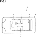
- FIG. 1 is a block diagram schematically showing an in-vehicle system according to a first embodiment.
- the in-vehicle system 1 includes an in-vehicle terminal 3 mounted in a vehicle 2, and a portable information terminal 4 that a driver of the vehicle 2 owns.
- a driver of the vehicle 2 Among occupants of the vehicle 2, occupants other than the driver will be referred to as passengers in the following description.
- the in-vehicle system 1 recognizes occupants who carry portable information terminals, by detecting the portable information terminals.
- the in-vehicle system 1 includes an occupant database (as described hereinafter) that associates portable information terminals with occupants.
- the in-vehicle system 1 retrieves the detected portable information terminals from the occupant database to identify corresponding occupants.
- the portable information terminal 4 that the driver owns will be referred to as a main terminal 4 and distinguished from portable information terminals 5 that passengers own.
- FIG. 2 is a block diagram schematically showing a configuration of the in-vehicle terminal 3.
- the in-vehicle terminal 3 includes a control unit 30, a ROM 31, a DRAM 32, an occupant database (DB) 33, a display unit 34, an input unit 35, a communication unit 36, a music DB 37, and an audio output unit 38.
- the control unit 30 is composed of a CPU (not shown) and its peripheral circuits.
- the ROM 31 is a nonvolatile storage medium. A predetermined control program has been stored in advance in the ROM 31.
- the control unit 30 controls the in-vehicle terminal 3 by reading the control program from the ROM 31 and executing the control program.
- the DRAM 32 is a temporary storage medium. The control unit 30 utilizes the DRAM 32 as a working storage area.
- the occupant DB 33 is a database that stores occupants who own portable information terminals. As schematically shown in FIG. 2 , the occupant DB 33 stores one or more identification information 33a, main terminal flags 33b, owner information 33c, and preference information 33d in such a manner that they are associated to one another.
- the identification information 33a is information indicating a Bluetooth (TM) Device Address (BD_ADDR) of a portable information terminal.
- BD_ADDR Device Address
- the main terminal flag 33b is information indicating whether the respective portable information terminal is the main terminal 4 or not.
- the owner information 33c is information indicating an owner of the respective portable information terminal.
- the preference information 33d is information indicating a music genre matched with the preference of the owner of the respective portable information terminal.
- the display unit 34 is a display device such as a liquid crystal monitor, for example.
- the control unit 30 displays a variety of images and texts on the display unit 34.
- the input unit 35 is an input device such as a touch panel, for example.
- the communication unit 36 wirelessly communicates with the main terminal 4 and the portable information terminals 5.
- the communication unit 36 is a communication module that complies with the Bluetooth standard, for example.
- the communication unit 36 has a measurement unit 361.
- the measurement unit 361 measures electric field strengths of radio waves sent out from the main terminal 4 and the portable information terminals 5 located in the vicinity thereof, before the wireless communication.
- the music DB 37 is a database in which a plurality of music data are stored. As schematically shown in FIG. 2 , the music DB 37 stores a plurality of music information 37a and category information 37b in such a manner that they are associated with each other.
- the music information 37a is digital music data.
- the category information 37b is information indicating genres to which the respective music information 37a belongs. Each music information 37a belongs to one or more genres.
- the control unit 30 has a main terminal identifying unit 301 and a music reproducing unit 302.
- the main terminal identifying unit 301 and the music reproducing unit 302 are functional units in the form of software whose functions are achieved by the control unit 30 executing the control program. It will be noted that each of these functional units may be composed of electronic circuits.
- the main terminal identifying unit 301 identifies the main terminal 4 from portable information terminals located in the vicinity thereof (as described hereinafter in detail).
- the music reproducing unit 302 outputs audio signals produced from the music information 37a to the audio output unit 38.
- the audio output unit 38 is connected to a speaker (not shown) or the like. In other words, the music reproducing unit 302 reproduces the music information 37a by means of the speaker (not shown) or the like.
- FIG. 3 is a block diagram schematically showing a configuration of the main terminal 4.
- the main terminal 4 includes a control unit 40, a ROM 41, a DRAM 42, a display unit 44, an input unit 45, and a communication unit 46.
- the control unit 40 is composed of a CPU (not shown) and its peripheral circuits.
- the ROM 41 is an nonvolatile storage medium. A predetermined control program has been stored in advance in the ROM 41.
- the control unit 40 controls the main terminal 4 by reading the control program from the ROM 41 and executing the control program.
- the DRAM 42 is a temporary storage medium. The control unit 40 utilizes the DRAM 42 as a working storage area.
- the display unit 44 is a display device such as a liquid crystal monitor, for example.
- the control unit 40 displays a variety of images and texts on the display unit 44.
- the input unit 45 is an input device such as a touch panel, for example.
- the communication unit 46 wirelessly communicates with the in-vehicle terminal 3 and the portable information terminals 5.
- the communication unit 46 is a communication module that complies with the Bluetooth standard, for example.
- the communication unit 46 has a measurement unit 461.
- the measurement unit 461 measures electric field strengths of radio waves sent out from the in-vehicle terminal 3 and the portable information terminals 5 located in the vicinity thereof, before the wireless communication.
- the control unit 40 has a position determining unit 401.
- the position determining unit 401 is a functional unit in the form of software whose function is achieved by the control unit 40 executing the control program.
- the position determining unit 401 determines a positional relationship between the in-vehicle terminal 3, the main terminal 4, and the portable information terminals 5 (as described hereinafter in detail).
- the occupant DB 33 stores information about an owner for each portable information terminal (owner information 33c) and information about a preference of the respective owner (preference information 33d).
- owner information 33c information about an owner for each portable information terminal
- preference information 33d information about a preference of the respective owner
- the information about the main terminal 4 is stored at the initial setting time of the in-vehicle system 1, for example. If the Bluetooth is used as a communication scheme, the initial setting is a so-called pairing process.
- the information about the portable information terminals 5 other than the main terminal 4 is manually registered by the driver who carries the main terminal 4. A specific registration procedure will be described below.
- the position determining unit 401 of the main terminal 4 determines positions of the portable information terminals 5 located in the vicinity thereof (as described hereinafter in detail).
- the control unit 40 of the main terminal 4 transmits the identification information 33a of the portable information terminals 5 located in the vicinity thereof and the positions of the portable information terminals 5 determined by the position determining unit 401 to the in-vehicle terminal 3.
- the control unit 30 of the in-vehicle terminal 3 determines whether the identification information 33a is included in the occupant DB 33 or not. In other words, the control unit 30 determines whether the portable information terminal 5 identified by the identification information 33a has already been registered or not. On the basis of this determination result, the control unit 30 displays the position of the portable information terminal 5 on the display unit 34.
- FIG. 4 is an example of a screen image that displays the positions of the portable information terminals 5.
- the control unit 30 displays an image 60 schematically representing a vehicle interior of the vehicle 2 on the display unit 34.
- the control unit 30 displays registered-terminal icons 61 indicating positions of the main terminal 4 and portable information terminals 5 that have already been registered in the occupant DB 33, and unregistered-terminal icons 62 indicating portable information terminals 5 that has not been registered in the occupant DB 33, in such a manner that they are superimposed on the image 60.
- the main terminal 4 and the registered portable information terminals 5 may be displayed by different icons to each other.
- the driver can perform a registration operation of registering the portable information terminal 5 corresponding to the unregistered-terminal icon 62 to the occupant DB 33.
- the driver touches the unregistered-terminal icon 62 via the input unit 35, which is a touch panel.
- the control unit 30 displays an input box or the like for input of information about the portable information terminal 5 corresponding to the unregistered-terminal icon 62 touched by the driver, on the display unit 34.
- the driver inputs the owner information 33c and the preference information 33d in the displayed input box or the like.
- the control unit 30 associates the identification information 33a of the portable information terminal 5 corresponding to the unregistered-terminal icon 62 touched by the driver with the owner information 33c and the preference information 33d which are here input, and then stores (registers) the information in the occupant DB 33. It will be noted that since the portable information terminal 5 that is newly registered here is not the main terminal 4, the control unit 30 stores the portable information terminal 5 with its main terminal flag 33b of 0 in the occupant DB 33.
- control unit 30 changes the unregistered-terminal icon 62 that has been displayed on the display unit 34 into an registered-terminal icon 61.
- the music reproducing unit 302 selects and reproduces music information 37a matched with the preferences of the occupants of the vehicle 2 from a large number of music information 37a stored in the music DB 37. For example, when the driver instructs the in-vehicle terminal 3 to reproduce music via the input unit 35 or the like, the music reproducing unit 302 executes a music reproducing process. The music reproducing process will now be described in detail.
- the music reproducing unit 302 retrieves the identification information 33a of the main terminal 4 and the portable information terminals 5 that are present in the vehicle 2, from the occupant DB 33. If the identification information 33a has been registered in the occupant DB 33, the music reproducing unit 302 reads out corresponding preference information 33d from the occupant DB 33.
- the music reproducing unit 302 retrieves music information 37a associated with category information 37b that includes at least one of genres included in the read-out preference information 33d, from the music DB 37. For example, if the read-out preference information 33d includes two genres, "pop" and "rock", the music reproducing unit 302 retrieves music information 37a having its corresponding category information 37b that includes at least one of "pop" and "rock".
- the music reproducing unit 302 retrieves the music information 37a from the preference information 33d on the basis of an union of genres included in the plurality of preference information 33d. In other words, the music reproducing unit 302 retrieves music information 37a associated with category information 37b that includes at least one of genres included in either one of the plurality of preference information 33d.
- the music reproducing unit 302 selects and reproduces one arbitrary music information 37a, among the music information 37a included in the retrieval result. It will be noted that if the identification information 33a of a portable information terminal 5 that is present in the vehicle 2 is not included in the occupant DB 33, the music reproducing unit 302 ignores this portable information terminal 5.
- the music reproducing unit 302 selects and reproduces the music information 37a belonging to the genres matched with the preferences of the occupants from a large number of music information 37a.
- a method of determining a position of a portable information terminal 5 by means of the in-vehicle system 1 will be described.
- the in-vehicle terminal 3 and the main terminal 4 execute a terminal position determining process as described below in detail.
- the control unit 30 of the in-vehicle terminal 3 displays the position of the portable information terminal 5 determined by the terminal position determining process on the display unit 34.
- the terminal position determining process is started by the control unit 30 of the in-vehicle terminal 3.
- the control unit 30 causes the communication unit 36 to detect portable information terminals located in the vicinity thereof.
- the communication unit 36 performs a Bluetooth inquiry operation, for example, and sends out radio signals (inquiry signals) for causing portable information terminals located in the vicinity thereof to provide information about themselves.
- radio signals inquiry signals
- the communication unit 36 of the in-vehicle terminal 3 receives the response signals sent out from each portable information terminals.
- the communication unit 36 obtains a list of portable information terminals that are present in the vicinity thereof, by listing the identification information 33a included in the received response signals.
- the measurement unit 361 measures electric field strengths of the response signals.
- the control unit 30 associates the electric field strengths measured by the measurement unit 361 with the list of portable information terminals obtained by the communication unit 36 (the list of the identification information 33a) and then keeps this information in the DRAM 32.
- the main terminal identifying unit 301 retrieves each identification information 33a kept in the DRAM 32, from the occupant DB 33. Thereby, the identification information 33a kept in the DRAM 32 is categorized into the identification information 33a that has already been registered in the occupant DB 33 and the (unregistered) identification information 33a that has not been registered in the occupant DB 33.
- the main terminal identifying unit 301 further categorizes the identification information 33a that has already been registered in the occupant DB 33 into the identification information 33a of the main terminal 4 and the identification information 33a of the portable information terminals 5 which are not the main terminal 4, by referring to the values of the main terminal flags 33b. In other words, the main terminal identifying unit 301 identifies the main terminal 4 among the portable information terminals. Namely, at this point of time, the portable information terminals present in the vicinity of the main terminal identifying unit 301 are categorized into the main terminal 4, the registered portable information terminals 5, and the unregistered portable information terminals 5.
- the control unit 30 establishes wireless communication with the main terminal 4.
- the control unit 30 transmits the electric field strength measured for the main terminal 4 which is kept in the DRAM 32 and the identification information 33a and electric field strengths of other portable information terminals 5 which are kept in the DRAM 32, via the established wireless communication to the main terminal 4.
- the control unit 40 of the main terminal 4 keeps these information received by the communication unit 46 in the DRAM 42 of the main terminal 4. At this point of time, the following information are kept in the DRAM 42 of the main terminal 4.
- the position determining unit 401 of the main terminal 4 determines a relative positional relationship between the in-vehicle terminal 3 and the main terminal 4 on the basis of the above-described information (1).
- the in-vehicle terminal 3, the main terminal 4, and the portable information terminals 5 are located in a plane that is parallel to a floor of the vehicle 2 and is at a predetermined height, and the positional relationship in this plane will be considered.
- positional relationships in a vertical direction of the in-vehicle terminal 3, the main terminal 4, and the portable information terminals 5 will not be taken into consideration.
- FIG. 5 is a schematic view explaining a method of determining the relative positional relationship between the in-vehicle terminal 3 and the main terminal 4.
- a two-dimensional coordinate system is established, wherein the right direction of the vehicle 2 is the +x direction and the rear direction of the vehicle 2 is the +y direction.
- the position of the in-vehicle terminal 3 will be set as an origin and represented by a coordinate (0, 0).
- the electric field strength of the radio signal attenuates in proportion to a distance. Therefore, the position determining unit 401 can determine a length L0 from the in-vehicle terminal 3 to the main terminal 4, from the above-described information (1).
- the main terminal 4 is located on a circumference of a circle 64 having a radius L0, with the coordinate (0, 0) being as its center.
- the position determining unit 401 considers that the main terminal 4 is present at a position apart from the origin (0, 0) by a predetermined distance LD in the rear direction of the vehicle 2.
- the predetermined distance LD is a distance that is determined on the basis of the position of a driver seat of the vehicle 2.
- the main terminal 4 should be located either at a coordinate (-xd, LD) or at a coordinate (xd, LD), as shown in FIG. 5 .
- the position determining unit 401 determines the coordinate (xd, LD) as the position of the main terminal 4. If the vehicle 2 is a left-hand-drive vehicle, the position determining unit 401 determines the coordinate (-xd, LD) as the position of the main terminal 4. In the following description, the coordinate of the main terminal 4 determined here will be represented by (Xd, Yd).
- the predetermined distance LD may be adjustable by the driver as desired.
- the predetermined distance LD may vary depending on the position of the driver seat.
- the predetermined distance LD may vary also depending on the posture of the driver or a position where the main terminal 4 is carried. Because the driver can adjust the predetermined distance LD depending on the above-described situations, it is possible to determine the position of the main terminal 4 with a higher accuracy.
- the position determining unit 401 determines the coordinate (Xd, Yd) of the main terminal 4 by means of the above-described process, with the coordinate of the in-vehicle terminal 3 being (0, 0). In other words, the position determining unit 401 determines the relative positional relationship between the in-vehicle terminal 3 and the main terminal 4. On the basis of the thus determined positional relationship, the position determining unit 401 then determines the position of each portable information terminal 5.
- the position determining unit 401 causes the communication unit 46 to detect portable information terminals 5 located in the vicinity thereof.
- the communication unit 36 performs a Bluetooth inquiry operation, for example, and sends out radio signals (inquiry signals) for causing portable information terminals 5 located in the vicinity thereof to provide information about themselves.
- radio signals inquiry signals
- the communication unit 46 of the main terminal 4 receives the response signals sent out from the portable information terminals 5.
- the communication unit 46 obtains a list of portable information terminals that are present in the vicinity thereof, by listing the identification information 33a included in the received response signals.
- the measurement unit 461 measures electric field strengths of the response signals.
- the control unit 40 further associates the electric field strengths measured by the measurement unit 461 with the above-described information (2), (4) received from the in-vehicle terminal 3 and then keeps this information in the DRAM 42.
- the following information (6) to (8) are kept in the DRAM 42 of the main terminal 4, in addition to the information (1) to (5).
- the position determining unit 401 determines the position of each registered portable information terminal 5. Similarly, on the basis of the above-described information (5), (6) and (8), the position determining unit 401 then determines the position of each unregistered portable information terminal 5.
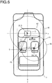
- FIG. 6 is a schematic view explaining a method of determining a position of a portable information terminal 5.
- the electric field strength of the radio signal attenuates in proportion to a distance. Therefore, the position determining unit 401 can determine a length L1 from the in-vehicle terminal 3 to the portable information terminal 5, from the above-described information (3) or (5).
- the portable information terminal 5 is located on a circumference of a circle 65 having a radius L1, with the coordinate (0, 0) being as its center. Further, the position determining unit 401 can determine a length L2 from the main terminal 4 to the portable information terminal 5, from the above-described information (7) or (8).
- the portable information terminal 5 is located on a circumference of a circle 66 having a radius L2, with the coordinate (Xd, Yd) being as its center. Thus, it is found that the portable information terminal 5 is located at either of intersection points P1, P2 of two circles 65, 66.
- the position determining unit 401 determines at which intersection point P1 or P2 the portable information terminal 5 is present, on the basis of a predetermined effective range 67.
- the predetermined effective range 67 is a range in which the occupants may be present, wherein the range is determined on the basis of dimensions of the vehicle interior of the vehicle 2. Considering the circle 65 having a radius L1 and the circle 66 having a radius L2, one of two intersection points P1, P2 of the circles 65, 66 may be located outside of the vehicle interior of the vehicle 2 as illustrated in FIG. 6 .
- the position determining unit 401 excludes the intersection point P1 among the two intersection points P1, P2 that is out of the effective range 67, from candidates for the position of the portable information terminal 5. In the example of FIG. 6 , the position determining unit 401 determines the intersection point P2 that is located within the effective range 67 as the position of the portable information terminal 5.
- the position determining unit 401 determines the position of each portable information terminal 5 that is present in the vicinity thereof, in accordance with the above-described procedure.
- the control unit 40 transmits positional information indicating the position of the main terminal 4 and positional information indicating the positions of portable information terminals 5, in association with the identification information 33a, to the in-vehicle terminal 3.
- the control unit 30 of the in-vehicle terminal 3 displays the positions of the main terminal 4 and the portable information terminals 5 on the display unit 34, on the basis of the received positional information.
- the position determining unit 401 handles the two points as the position of the portable information terminal 5.
- the control unit 30 displays the unregistered-terminal icons 62 or the registered-terminal icons 61 at both positions.
- the position determining unit 401 determines that the portable information terminal 5 is located outside of the vehicle interior and ignores this portable information terminal 5.
- FIGS. 7A to 7C are flowcharts of the terminal position determining process.
- FIG. 7A shows a process executed by the in-vehicle terminal 3.
- FIG. 7B shows a process executed by the main terminal 4.
- FIG. 7C shows a process executed by the portable information terminal 5.
- step S105 the communication unit 36 sends out inquiry signals to the main terminal 4 and the portable information terminals 5 located in the vicinity thereof.
- step S110 the communication unit 36 receives response signals sent out from the main terminal 4 and the portable information terminals 5 located in the vicinity thereof.
- step S115 the measurement unit 361 measures an electric field strength for each received response signal.
- step S120 the control unit 30 looks up the occupant DB 33 and categorizes sources of the response signals into the main terminal 4, the registered portable information terminals 5, and the unregistered portable information terminals 5.
- step S125 the communication unit 36 establishes wireless communication with the main terminal 4.
- step S130 the communication unit 36 transmits the identification information 33a included in the response signals received in step S110 and the electric field strength for each terminal measured in step S115 to the main terminal 4.
- step S160 the communication unit 36 receives positional information for each terminal transmitted from the main terminal 4.
- control program executed by the control unit 30 of the in-vehicle terminal 3 includes: a measuring step of measuring electric field strengths of radio waves for wireless communication emitted from portable information terminals located in the vicinity thereof; a main terminal identifying step of identifying a main terminal 4 among the portable information terminals; and a communicating step of establishing wireless communication with the identified main terminal 4 and transmitting electric field strengths for other portable information terminals 5 than the main terminal 4 measured by the measuring step, via the wireless communication to the main terminal 4.
- step S205 the communication unit 46 receives the inquiry signal sent out from the in-vehicle terminal 3.
- step S210 the communication unit 46 sends out a response signal including the identification information 33a of the main terminal 4 to the in-vehicle terminal 3.
- step S225 the communication unit 46 establishes wireless communication with the in-vehicle terminal 3.
- step S230 the communication unit 46 receives sets of the identification information 33a and the electric field strengths of the portable information terminals 5, which are transmitted from the in-vehicle terminal 3.
- step S235 the position determining unit 401 determines a relative positional relationship between the in-vehicle terminal 3 and the main terminal 4, on the basis of the electric field strength of the response signal sent out from the main terminal 4, as measured by the in-vehicle terminal 3. In other words, the position determining unit 401 determines the coordinate (Xd, Yd) of the main terminal 4, with the coordinate of the in-vehicle terminal 3 being (0, 0).
- the communication unit 46 sends out inquiry signals to the portable information terminals 5 located in the vicinity thereof.
- step S245 the communication unit 46 receives response signals sent out from the portable information terminals 5 located in the vicinity thereof.
- the measurement unit 461 measures an electric field strength for each received response signal.
- step S255 the position determining unit 401 determines the position of each portable information terminal 5, in accordance with the procedure explained in FIG. 6 .
- step S260 the communication unit 46 transmits positional information indicating the position of the identified main terminal 4 and the positions of the portable information terminals 5 to the in-vehicle terminal 3.
- step S305 the communication unit of the portable information terminal 5 receives the inquiry signal sent out from the in-vehicle terminal 3.
- the communication unit of the portable information terminal 5 sends out a response signal including the identification information 33a of the portable information terminal 5 to the in-vehicle terminal 3.
- step S340 the communication unit of the portable information terminal 5 receives the inquiry signal sent out from the main terminal 4.
- step S345 the communication unit of the portable information terminal 5 sends out a response signal including the identification information 33a of the portable information terminal 5 to the main terminal 4.
- the main terminal 4 has the position determining unit 401 that determines the positions of the portable information terminals 5. In other words, the main terminal 4 determines the position of each portable information terminal 5. In a second embodiment described below, the in-vehicle terminal 1003 determines the position of each portable information terminal 5.
- FIG. 8 is a block diagram schematically showing a configuration of the in-vehicle terminal 1003.
- the in-vehicle terminal 1003 is different from the in-vehicle terminal 3 shown in FIG. 2 in that the control unit 30 has the position determining unit 401.
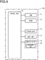
- FIG. 9 is a block diagram schematically showing a configuration of the main terminal 1004.
- the main terminal 1004 is different from the main terminal 4 shown in FIG. 3 in that the control unit 40 does not have any position determining unit.
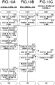
- FIGS. 10A to 10C are flowcharts of a terminal position determining process. It will be noted that the same processes as in the terminal position determining process ( FIGS. 7A to 7C ) according to the first embodiment are denoted by the same reference numerals as in the first embodiment.
- FIG. 10A shows a process executed by the in-vehicle terminal 1003.
- FIG. 10B shows a process executed by the main terminal 1004.
- FIG. 10C shows a process executed by the portable information terminal 5.
- step S105 the communication unit 36 sends out inquiry signals to the main terminal 4 and the portable information terminals 5 located in the vicinity thereof.
- step S110 the communication unit 36 receives response signals sent out from the main terminal 4 and the portable information terminals 5 located in the vicinity thereof.
- step S115 the measurement unit 361 measures an electric field strength for each received response signal. The electric field strength corresponding to each of the main terminal 1004 and the portable information terminals 5 measured here is kept by the DRAM 32.
- step S118 the position determining unit 401 determines a relative positional relationship between the in-vehicle terminal 1003 and the main terminal 1004, on the basis of the electric field strength of the response signal sent out from the main terminal 1004, as measured by the in-vehicle terminal 1003. In other words, the position determining unit 401 determines the coordinate (Xd, Yd) of the main terminal 1004, with the coordinate of the in-vehicle terminal 1003 being (0, 0).
- step S120 the control unit 30 looks up the occupant DB 33 and categorizes sources of the response signals into the main terminal 1004, the registered portable information terminals 5, and the unregistered portable information terminals 5.
- step S125 the communication unit 36 establishes wireless communication with the main terminal 1004.
- step S165 the communication unit 36 receives sets of the identification information 33a and the electric field strengths of the portable information terminals 5, which are transmitted from the main terminal 1004.
- step S170 the position determining unit 401 determines the position of each portable information terminal 5, in accordance with the procedure explained in FIG. 6 .
- the control program executed by the control unit 30 of the in-vehicle terminal 1003 includes: a measuring step of measuring electric field strengths of radio waves for wireless communication emitted from portable information terminals located in the vicinity thereof; a main terminal identifying step of identifying a main terminal 1004 among the portable information terminals; a keeping step of keeping electric field strengths for other portable information terminals 5 than the identified main terminal 1004 measured by the measuring step; and a communication step of establishing wireless communication with the main terminal 1004 and receiving the electric field strengths for other information terminals 5 measured by the main terminal 1004, from the main terminal 1004 via the wireless communication.
- step S205 the communication unit 46 receives the inquiry signal sent out from the in-vehicle terminal 1003.
- step S210 the communication unit 46 sends out a response signal including the identification information 33a of the main terminal 1004 to the in-vehicle terminal 1003.
- step S225 the communication unit 46 establishes wireless communication with the in-vehicle terminal 1003.
- step S240 the communication unit 46 sends out inquiry signals to portable information terminals 5 located in the vicinity thereof.
- step S245 the communication unit 46 receives the response signals sent out from the portable information terminals 5 located in the vicinity thereof.
- step S250 the measurement unit 461 measures an electric field strength for each received response signal.
- step S265 the communication unit 46 transmits the identification information 33a included in the response signals received in step S245 and the electric field strength for each terminal measured in step S250 to the in-vehicle terminal 1003.
- step S305 the communication unit of the portable information terminal 5 receives the inquiry signal sent out from the in-vehicle terminal 1003.
- step S310 the communication unit of the portable information terminal 5 sends out a response signal including the identification information 33a of the portable information terminal 5 to the in-vehicle terminal 1003.
- step S340 the communication unit of the portable information terminal 5 receives the inquiry signal sent out from the main terminal 1004.
- step S345 the communication unit of the portable information terminal 5 sends out a response signal including the identification information 33a of the portable information terminal 5 to the main terminal 1004.
- the positions of the portable information terminals 5 determined by the position determining unit 401 are used for display on the display unit 34.
- the positions of the portable information terminals 5 determined by the position determining unit 401 may be used for other purposes.
- the positional information may be used for preventing the occupants to leave the portable information terminals 5 behind in the vehicle 2 when they get off the vehicle 2, with an alarm or the like.
- air conditioning is turned to be active only in places where the portable information terminals 5 are present, while air conditioning is inactive in other places, so that an energy-saving air conditioning feature can be achieved.
- the music reproducing feature that provides music optimized for the occupants has been described.
- information about whether the occupant is sensitive to heat or cold has been stored in the occupant DB 33 as preference information 33d.
- the control unit 30 changes an air volume or temperature setting of an air conditioner in accordance with the preference information 33d, so that an air conditioning feature that provides air conditioning optimized for the occupants can be implemented.
- the position determining unit 401 may determine a positional relationship between the in-vehicle terminal 3 (or the in-vehicle terminal 1003; the same shall apply hereinafter) and the main terminal 4 (or the main terminal 1004; the same shall apply hereinafter), on the basis of the electric field strength of the radio signal emitted from the in-vehicle terminal 3, as measured by the main terminal 4.
- a personal computer 400 may be provided with the programs through a CD-ROM 404.
- the personal computer 400 has a connect function to a communication line 401.
- a computer 402, which is a server computer that provides the programs described above, may store them on a recording medium such as a hard disk 403.
- the communication line 401 is a communication line such as the Internet or a personal computer communication, or a leased line, etc.
- the computer 402 may read out the programs using the hard disk 403, send them to the personal computer 400 through the communication line 401.
- the programs may be embodied on a carrier wave as a data signal, and sent through the communication line 401.
- the programs can be provided as a computer-readable computer program product in a variety of forms such as recording medium, a carrier wave, etc.
- positions of occupants can be detected without adding any dedicated components.
Landscapes
- Engineering & Computer Science (AREA)
- Computer Networks & Wireless Communication (AREA)
- Signal Processing (AREA)
- Mechanical Engineering (AREA)
- Physics & Mathematics (AREA)
- Transportation (AREA)
- Aviation & Aerospace Engineering (AREA)
- Remote Sensing (AREA)
- Radar, Positioning & Navigation (AREA)
- General Physics & Mathematics (AREA)
- Mobile Radio Communication Systems (AREA)
- Electromagnetism (AREA)
- Quality & Reliability (AREA)
- Traffic Control Systems (AREA)
- Telephone Function (AREA)
Claims (13)
- Bordinternes Endgerät (3; 1003), das Folgendes umfasst:eine Messeinheit (361), die elektrische Feldstärken von Funkwellen für drahtlose Kommunikation misst, die von tragbaren Informationsendgeräten emittiert werden, die sich in ihrer Nähe befinden;eine Hauptendgerätidentifizierungseinheit (301), die ein vorgegebenes Hauptendgerät (4) unter den tragbaren Informationsendgeräten identifiziert; undeine Kommunikationseinheit (36), die eine drahtlose Verbindung mit dem identifizierten Hauptendgerät (4) aufbaut und eine erste elektrische Feldstärke für ein anderes tragbares Informationsendgerät (5) als das Hauptendgerät (4), die von der Messeinheit gemessen wird, über die drahtlose Verbindung an das Hauptendgerät (4) sendet.
- Bordinternes Endgerät (3; 1003) nach Anspruch 1, wobei
die Messeinheit (361) eine elektrische Feldstärke einer Funkwelle, die von dem Hauptendgerät (4) emittiert wird, misst, wenn die Kommunikationseinheit (36) die drahtlose Verbindung aufbaut. - Bordinternes Endgerät (3; 1003) nach Anspruch 1 oder 2, wobei
die Kommunikationseinheit (36) eine zweite elektrische Feldstärke für das Hauptendgerät (4), die von der Messeinheit (361) gemessen wird, über die drahtlose Verbindung an das Hauptendgerät (4) sendet. - Bordinternes Endgerät (3; 1003) nach Anspruch 1 bis 3, wobei
die Kommunikationseinheit (36) Positionsinformationen des anderen tragbaren Informationsendgeräts (5), die von dem Hauptendgerät (4) berechnet werden, von dem Hauptendgerät (4) über die drahtlose Verbindung empfängt. - Bordinternes Endgerät (3; 1003) nach Anspruch 4, das ferner Folgendes umfasst:
eine Anzeigeeinheit (34), die eine Position des anderen tragbaren Informationsendgeräts (5) auf der Grundlage der Positionsinformationen des anderen tragbaren Informationsendgeräts (5), die von der Kommunikationseinheit (36) empfangen werden, anzeigt. - Bordinternes Endgerät (3; 1003), das Folgendes umfasst:eine Messeinheit (361), die elektrische Feldstärken von Funkwellen für drahtlose Kommunikation misst, die von tragbaren Informationsendgeräten emittiert werden, die sich in ihrer Nähe befinden;eine Hauptendgerätidentifizierungseinheit (301), die ein vorgegebenes Hauptendgerät (4) unter den tragbaren Informationsendgeräten identifiziert;eine Beibehaltungseinheit (32), die eine erste elektrische Feldstärke für ein anderes tragbares Informationsendgerät (5) als das identifizierte Hauptendgerät (4), die von der Messeinheit (361) gemessen wird, beibehält; undeine Kommunikationseinheit (36), die eine drahtlose Verbindung mit dem Hauptendgerät (4) aufbaut und eine zweite elektrische Feldstärke für das andere tragbare Informationsendgerät (5), die von dem Hauptendgerät (4) gemessen wird, von dem Hauptendgerät (4) über die drahtlose Verbindung empfängt.
- Bordinternes Endgerät (3; 1003) nach Anspruch 6, wobei
die Messeinheit (361) eine elektrische Feldstärke einer Funkwelle misst, die von dem Hauptendgerät (4) emittiert wird, wenn die Kommunikationseinheit (36) die drahtlose Verbindung aufbaut. - Bordinternes Endgerät (1003) nach Anspruch 6 oder 7, wobei
die Beibehaltungseinheit (32) ferner eine dritte elektrische Feldstärke für das Hauptendgerät (4) beibehält, die von der Messeinheit (4) gemessen wird; und
das bordinterne Endgerät (1003) ferner Folgendes umfasst:
eine Positionsbestimmungseinheit (401), die eine Positionsbeziehung zwischen dem bordinternen Endgerät (1003) und dem Hauptendgerät (4) auf der Grundlage der dritten elektrischen Feldstärke bestimmt. - Bordinternes Endgerät (1003) nach Anspruch 8, wobei
die Positionsbestimmungseinheit (401) ferner eine Position des anderen tragbaren Endgeräts (5) auf der Grundlage der Positionsbeziehung, der ersten elektrischen Feldstärke und der zweiten elektrischen Feldstärke bestimmt. - Bordinternes Endgerät (1003) nach Anspruch 8 oder 9, wobei
dann, wenn mehrere Kandidaten für die Position des anderen tragbaren Informationsendgeräts (5), die auf der Grundlage der Positionsbeziehung, der ersten elektrischen Feldstärke und der zweiten elektrischen Feldstärke bestimmt werden, existieren, die Positionsbestimmungseinheit (401) die Position des anderen tragbaren Informationsendgeräts durch Ausschließen von Kandidaten, die außerhalb eines vorgegebenen Bereichs vorliegen, bestimmt. - Bordinternes Endgerät (1003) nach Anspruch 8 bis 10, das ferner Folgendes umfasst:
eine Anzeigeeinheit (34), die die Position des anderen tragbaren Endgeräts (5), die von der Positionsbestimmungseinheit (401) bestimmt wird, anzeigt. - Verfahren, das Folgendes umfasst:einen Messschritt des Messens elektrischer Feldstärken von Funkwellen für drahtlose Kommunikation, die von tragbaren Informationsendgeräten emittiert werden, die sich in ihrer Nähe befinden;einen Hauptendgerätidentifizierungsschritt des Identifizierens eines vorgegebenen Hauptendgeräts (4) unter den tragbaren Informationsendgeräten; undeinen Kommunikationsschritt des Aufbauens einer drahtlosen Verbindung mit dem identifizierten Hauptendgerät (4) und des Sendens einer ersten elektrischen Feldstärke für ein anderes tragbares Informationsendgerät (5) als das Hauptendgerät (4), die in dem Messschritt gemessen wird, über die drahtlose Verbindung an das Hauptendgerät (4).
- Verfahren, das Folgendes umfasst:einen Messschritt des Messens elektrischer Feldstärken von Funkwellen für drahtlose Kommunikation, die von tragbaren Informationsendgeräten emittiert werden, die sich in der Nähe davon befinden;einen Hauptendgerätidentifizierungsschritt des Identifizierens eines vorgegebenen Hauptendgeräts (4) unter den tragbaren Informationsendgeräten;einen Beibehaltungsschritt des Beibehaltens einer ersten elektrischen Feldstärke für ein anderes Informationsendgerät (5) als das identifizierte Hauptendgerät (4), die in dem Messschritt gemessen wird; undeinen Kommunikationsschritt des Aufbauens einer drahtlosen Verbindung mit dem Hauptendgerät (4) und des Empfangens einer zweiten elektrischen Feldstärke für das andere tragbare Informationsendgerät (5), die von dem Hauptendgerät (4) gemessen wird, über die drahtlose Verbindung von dem Hauptendgerät (4).
Applications Claiming Priority (1)
| Application Number | Priority Date | Filing Date | Title |
|---|---|---|---|
| JP2015137691A JP6539133B2 (ja) | 2015-07-09 | 2015-07-09 | 車載端末およびプログラム |
Publications (2)
| Publication Number | Publication Date |
|---|---|
| EP3115262A1 EP3115262A1 (de) | 2017-01-11 |
| EP3115262B1 true EP3115262B1 (de) | 2018-06-27 |
Family
ID=56408995
Family Applications (1)
| Application Number | Title | Priority Date | Filing Date |
|---|---|---|---|
| EP16178639.7A Active EP3115262B1 (de) | 2015-07-09 | 2016-07-08 | Fahrzeuginternes endgerät |
Country Status (3)
| Country | Link |
|---|---|
| US (1) | US9813170B2 (de) |
| EP (1) | EP3115262B1 (de) |
| JP (1) | JP6539133B2 (de) |
Families Citing this family (4)
| Publication number | Priority date | Publication date | Assignee | Title |
|---|---|---|---|---|
| KR101967670B1 (ko) * | 2012-06-15 | 2019-04-11 | 삼성전자주식회사 | 단말들 간의 무선 통신 방법 |
| KR102039318B1 (ko) * | 2016-01-26 | 2019-11-01 | 베이징 디디 인피니티 테크놀로지 앤드 디벨럽먼트 컴퍼니 리미티드 | 루트-상 수송들을 모니터링하기 위한 시스템들 및 방법들 |
| WO2018203945A2 (en) * | 2017-02-06 | 2018-11-08 | Power Survey Llc | Apparatus and method for detection of hazardously energized objects |
| US11300649B1 (en) * | 2017-06-24 | 2022-04-12 | Robotic Research Opco, Llc | Vehicle localization augmentation for dismounts |
Family Cites Families (25)
| Publication number | Priority date | Publication date | Assignee | Title |
|---|---|---|---|---|
| JP2003248045A (ja) | 2002-02-22 | 2003-09-05 | Alpine Electronics Inc | 車室内乗員位置検出装置および車載機器制御システム |
| JP2004297201A (ja) | 2003-03-25 | 2004-10-21 | Fujitsu Ltd | 携帯電話探索システム及び探索方法 |
| JP4620054B2 (ja) | 2004-06-24 | 2011-01-26 | パナソニック株式会社 | 携帯端末とこれを用いた無線品質表示方法、プログラム、及びシステム |
| MY163773A (en) * | 2005-09-13 | 2017-10-31 | Taiwan Semiconductor Mfg Co Ltd | Position determination of mobile stations in a wireless network |
| WO2007099743A1 (ja) * | 2006-02-28 | 2007-09-07 | Matsushita Electric Industrial Co., Ltd. | 無線通信装置及びその通信方法 |
| CN101064911B (zh) * | 2006-04-28 | 2012-08-22 | 上海贝尔阿尔卡特股份有限公司 | 无线接入系统的切换控制方法、中继站和基站 |
| JP2008042577A (ja) * | 2006-08-07 | 2008-02-21 | Toyota Motor Corp | 車載装置 |
| US20080077261A1 (en) * | 2006-08-29 | 2008-03-27 | Motorola, Inc. | Method and system for sharing an audio experience |
| KR101203461B1 (ko) * | 2006-11-10 | 2012-11-21 | 삼성전자주식회사 | 멀티홉 셀룰러 시스템에서의 라우팅 방법 및 상기 멀티홉셀룰러 시스템 |
| US8145199B2 (en) * | 2009-10-31 | 2012-03-27 | BT Patent LLC | Controlling mobile device functions |
| DE102010002928B4 (de) * | 2010-03-16 | 2023-11-02 | Bayerische Motoren Werke Aktiengesellschaft | Kraftfahrzeugkonfigurationssystem |
| US8812065B2 (en) * | 2010-06-07 | 2014-08-19 | Ford Global Technologies, Llc | System and method for monitoring the location of a communication device in a vehicle based on signal strength |
| JP2012132821A (ja) | 2010-12-22 | 2012-07-12 | Aisin Aw Co Ltd | 車載制御装置、車載制御方法及び車載制御用プログラム |
| JP5866877B2 (ja) | 2011-08-30 | 2016-02-24 | 大日本印刷株式会社 | 位置検出システム、端末装置及び位置検出プログラム |
| US9088572B2 (en) | 2011-11-16 | 2015-07-21 | Flextronics Ap, Llc | On board vehicle media controller |
| JP5861769B2 (ja) * | 2012-03-30 | 2016-02-16 | 富士通株式会社 | 無線通信方法、ノードおよび監視ノード |
| US8914043B2 (en) * | 2012-04-18 | 2014-12-16 | Google Inc. | Creating and sharing private location databases |
| WO2014118647A2 (en) * | 2013-01-09 | 2014-08-07 | Nathanson Martin D | Vehicle communications via wireless access vehicular environment |
| DE102013201959B4 (de) * | 2013-02-06 | 2024-03-21 | Bayerische Motoren Werke Aktiengesellschaft | Erweiterte Personalisierung von Fahrzeugeinstellungen |
| US10052972B2 (en) * | 2013-03-26 | 2018-08-21 | Intel Corporation | Vehicular occupancy assessment |
| JP2014225209A (ja) | 2013-05-17 | 2014-12-04 | 住友電工システムソリューション株式会社 | 通信システム、通信アダプタおよび通信方法 |
| US9248794B2 (en) | 2013-08-26 | 2016-02-02 | Intel Corporation | Configuring user customizable operational features of a vehicle |
| KR101710317B1 (ko) * | 2013-11-22 | 2017-02-24 | 퀄컴 인코포레이티드 | 차량 내의 다수의 모바일 컴퓨팅 디바이스들에 의해 제공된 선호도들에 기초하여 차량의 내면을 구성하기 위한 시스템 및 방법 |
| US9232495B2 (en) * | 2013-12-06 | 2016-01-05 | Location Labs, Inc. | Device association-based locating system and method |
| KR101568335B1 (ko) * | 2014-11-26 | 2015-11-12 | 현대자동차주식회사 | 차량에서의 블루투스 페어링 제공 방법 및 장치 |
-
2015
- 2015-07-09 JP JP2015137691A patent/JP6539133B2/ja active Active
-
2016
- 2016-07-08 EP EP16178639.7A patent/EP3115262B1/de active Active
- 2016-07-08 US US15/205,409 patent/US9813170B2/en active Active
Non-Patent Citations (1)
| Title |
|---|
| None * |
Also Published As
| Publication number | Publication date |
|---|---|
| US9813170B2 (en) | 2017-11-07 |
| JP2017022512A (ja) | 2017-01-26 |
| EP3115262A1 (de) | 2017-01-11 |
| US20170012721A1 (en) | 2017-01-12 |
| JP6539133B2 (ja) | 2019-07-03 |
Similar Documents
| Publication | Publication Date | Title |
|---|---|---|
| US10470131B2 (en) | Electronic device for controlling communication circuit based on identification information received from external device and operation method thereof | |
| CN106156241B (zh) | 可穿戴装置及其控制方法 | |
| EP3270245B1 (de) | Verfahren, server, mobiles endgerät und vorrichtung zur interaktion von daten mit einer fahrzeugmontierten maschine | |
| US20200159481A1 (en) | Method for controlling display of vehicle and electronic device therefor | |
| CN107430524B (zh) | 一种定位声音发出位置的方法和终端设备 | |
| AU2014284934A1 (en) | Electronic device and method for controlling multi-windows in the electronic device | |
| US9813170B2 (en) | In-vehicle terminal that measures electric field strengths of radio waves from information terminals | |
| WO2021238452A1 (zh) | 一种确定密切接触者的方法、终端设备及服务器 | |
| JP2014004860A (ja) | 車載端末および通信方法 | |
| CN109240281B (zh) | 避让行驶方法及相关产品 | |
| CN106126675A (zh) | 一种推荐音频的方法、装置及系统 | |
| KR101936090B1 (ko) | 키 입력 제어 장치 및 방법 | |
| CN108683812B (zh) | 音量调节方法、装置以及移动终端 | |
| US20150002417A1 (en) | Method of processing user input and apparatus using the same | |
| EP3838683B1 (de) | Fahrzeuginterne erkennung einer nur-lade-verbindung mit einer mobilen rechenvorrichtung | |
| US9369417B2 (en) | On-vehicle apparatus, terminal device, and information transmission control method | |
| CN106375950A (zh) | 通信方法、车载设备和终端设备 | |
| KR102611775B1 (ko) | 그룹 메시지의 전달 방법 및 이를 수행하는 전자 장치 | |
| CN104901992A (zh) | 一种资源转移的方法和装置 | |
| CN114598992A (zh) | 信息交互方法、装置、设备及计算机可读存储介质 | |
| JP2014221620A (ja) | 表示制御装置、及び、プログラム | |
| US20220324325A1 (en) | Vehicular electronic device, mobile device for controlling the vehicular electronic device, and method of controlling the vehicular electronic device by using the mobile device | |
| CN116913085A (zh) | 一种辅助跟车方法、装置、电子设备及存储介质 | |
| CN108871356B (zh) | 一种行车导航方法、移动终端 | |
| CN104244452A (zh) | 通信系统以及确定方法 |
Legal Events
| Date | Code | Title | Description |
|---|---|---|---|
| PUAI | Public reference made under article 153(3) epc to a published international application that has entered the european phase |
Free format text: ORIGINAL CODE: 0009012 |
|
| STAA | Information on the status of an ep patent application or granted ep patent |
Free format text: STATUS: REQUEST FOR EXAMINATION WAS MADE |
|
| 17P | Request for examination filed |
Effective date: 20160916 |
|
| AK | Designated contracting states |
Kind code of ref document: A1 Designated state(s): AL AT BE BG CH CY CZ DE DK EE ES FI FR GB GR HR HU IE IS IT LI LT LU LV MC MK MT NL NO PL PT RO RS SE SI SK SM TR |
|
| AX | Request for extension of the european patent |
Extension state: BA ME |
|
| GRAP | Despatch of communication of intention to grant a patent |
Free format text: ORIGINAL CODE: EPIDOSNIGR1 |
|
| STAA | Information on the status of an ep patent application or granted ep patent |
Free format text: STATUS: GRANT OF PATENT IS INTENDED |
|
| RIC1 | Information provided on ipc code assigned before grant |
Ipc: H04L 29/08 20060101ALI20180105BHEP Ipc: B60N 2/00 20060101ALI20180105BHEP Ipc: H04W 4/02 20180101ALI20180105BHEP Ipc: B60R 16/037 20060101AFI20180105BHEP |
|
| INTG | Intention to grant announced |
Effective date: 20180202 |
|
| GRAS | Grant fee paid |
Free format text: ORIGINAL CODE: EPIDOSNIGR3 |
|
| GRAA | (expected) grant |
Free format text: ORIGINAL CODE: 0009210 |
|
| STAA | Information on the status of an ep patent application or granted ep patent |
Free format text: STATUS: THE PATENT HAS BEEN GRANTED |
|
| AK | Designated contracting states |
Kind code of ref document: B1 Designated state(s): AL AT BE BG CH CY CZ DE DK EE ES FI FR GB GR HR HU IE IS IT LI LT LU LV MC MK MT NL NO PL PT RO RS SE SI SK SM TR |
|
| REG | Reference to a national code |
Ref country code: GB Ref legal event code: FG4D |
|
| REG | Reference to a national code |
Ref country code: AT Ref legal event code: REF Ref document number: 1012009 Country of ref document: AT Kind code of ref document: T Effective date: 20180715 |
|
| REG | Reference to a national code |
Ref country code: IE Ref legal event code: FG4D |
|
| REG | Reference to a national code |
Ref country code: DE Ref legal event code: R096 Ref document number: 602016003786 Country of ref document: DE |
|
| REG | Reference to a national code |
Ref country code: FR Ref legal event code: PLFP Year of fee payment: 3 |
|
| PG25 | Lapsed in a contracting state [announced via postgrant information from national office to epo] |
Ref country code: FI Free format text: LAPSE BECAUSE OF FAILURE TO SUBMIT A TRANSLATION OF THE DESCRIPTION OR TO PAY THE FEE WITHIN THE PRESCRIBED TIME-LIMIT Effective date: 20180627 Ref country code: BG Free format text: LAPSE BECAUSE OF FAILURE TO SUBMIT A TRANSLATION OF THE DESCRIPTION OR TO PAY THE FEE WITHIN THE PRESCRIBED TIME-LIMIT Effective date: 20180927 Ref country code: NO Free format text: LAPSE BECAUSE OF FAILURE TO SUBMIT A TRANSLATION OF THE DESCRIPTION OR TO PAY THE FEE WITHIN THE PRESCRIBED TIME-LIMIT Effective date: 20180927 Ref country code: SE Free format text: LAPSE BECAUSE OF FAILURE TO SUBMIT A TRANSLATION OF THE DESCRIPTION OR TO PAY THE FEE WITHIN THE PRESCRIBED TIME-LIMIT Effective date: 20180627 Ref country code: LT Free format text: LAPSE BECAUSE OF FAILURE TO SUBMIT A TRANSLATION OF THE DESCRIPTION OR TO PAY THE FEE WITHIN THE PRESCRIBED TIME-LIMIT Effective date: 20180627 |
|
| REG | Reference to a national code |
Ref country code: NL Ref legal event code: MP Effective date: 20180627 |
|
| REG | Reference to a national code |
Ref country code: LT Ref legal event code: MG4D |
|
| PG25 | Lapsed in a contracting state [announced via postgrant information from national office to epo] |
Ref country code: HR Free format text: LAPSE BECAUSE OF FAILURE TO SUBMIT A TRANSLATION OF THE DESCRIPTION OR TO PAY THE FEE WITHIN THE PRESCRIBED TIME-LIMIT Effective date: 20180627 Ref country code: RS Free format text: LAPSE BECAUSE OF FAILURE TO SUBMIT A TRANSLATION OF THE DESCRIPTION OR TO PAY THE FEE WITHIN THE PRESCRIBED TIME-LIMIT Effective date: 20180627 Ref country code: GR Free format text: LAPSE BECAUSE OF FAILURE TO SUBMIT A TRANSLATION OF THE DESCRIPTION OR TO PAY THE FEE WITHIN THE PRESCRIBED TIME-LIMIT Effective date: 20180928 Ref country code: LV Free format text: LAPSE BECAUSE OF FAILURE TO SUBMIT A TRANSLATION OF THE DESCRIPTION OR TO PAY THE FEE WITHIN THE PRESCRIBED TIME-LIMIT Effective date: 20180627 |
|
| REG | Reference to a national code |
Ref country code: AT Ref legal event code: MK05 Ref document number: 1012009 Country of ref document: AT Kind code of ref document: T Effective date: 20180627 |
|
| PG25 | Lapsed in a contracting state [announced via postgrant information from national office to epo] |
Ref country code: NL Free format text: LAPSE BECAUSE OF FAILURE TO SUBMIT A TRANSLATION OF THE DESCRIPTION OR TO PAY THE FEE WITHIN THE PRESCRIBED TIME-LIMIT Effective date: 20180627 |
|
| PG25 | Lapsed in a contracting state [announced via postgrant information from national office to epo] |
Ref country code: EE Free format text: LAPSE BECAUSE OF FAILURE TO SUBMIT A TRANSLATION OF THE DESCRIPTION OR TO PAY THE FEE WITHIN THE PRESCRIBED TIME-LIMIT Effective date: 20180627 Ref country code: SK Free format text: LAPSE BECAUSE OF FAILURE TO SUBMIT A TRANSLATION OF THE DESCRIPTION OR TO PAY THE FEE WITHIN THE PRESCRIBED TIME-LIMIT Effective date: 20180627 Ref country code: IS Free format text: LAPSE BECAUSE OF FAILURE TO SUBMIT A TRANSLATION OF THE DESCRIPTION OR TO PAY THE FEE WITHIN THE PRESCRIBED TIME-LIMIT Effective date: 20181027 Ref country code: AT Free format text: LAPSE BECAUSE OF FAILURE TO SUBMIT A TRANSLATION OF THE DESCRIPTION OR TO PAY THE FEE WITHIN THE PRESCRIBED TIME-LIMIT Effective date: 20180627 Ref country code: RO Free format text: LAPSE BECAUSE OF FAILURE TO SUBMIT A TRANSLATION OF THE DESCRIPTION OR TO PAY THE FEE WITHIN THE PRESCRIBED TIME-LIMIT Effective date: 20180627 Ref country code: CZ Free format text: LAPSE BECAUSE OF FAILURE TO SUBMIT A TRANSLATION OF THE DESCRIPTION OR TO PAY THE FEE WITHIN THE PRESCRIBED TIME-LIMIT Effective date: 20180627 Ref country code: PL Free format text: LAPSE BECAUSE OF FAILURE TO SUBMIT A TRANSLATION OF THE DESCRIPTION OR TO PAY THE FEE WITHIN THE PRESCRIBED TIME-LIMIT Effective date: 20180627 |
|
| PG25 | Lapsed in a contracting state [announced via postgrant information from national office to epo] |
Ref country code: SM Free format text: LAPSE BECAUSE OF FAILURE TO SUBMIT A TRANSLATION OF THE DESCRIPTION OR TO PAY THE FEE WITHIN THE PRESCRIBED TIME-LIMIT Effective date: 20180627 Ref country code: IT Free format text: LAPSE BECAUSE OF FAILURE TO SUBMIT A TRANSLATION OF THE DESCRIPTION OR TO PAY THE FEE WITHIN THE PRESCRIBED TIME-LIMIT Effective date: 20180627 Ref country code: ES Free format text: LAPSE BECAUSE OF FAILURE TO SUBMIT A TRANSLATION OF THE DESCRIPTION OR TO PAY THE FEE WITHIN THE PRESCRIBED TIME-LIMIT Effective date: 20180627 |
|
| REG | Reference to a national code |
Ref country code: DE Ref legal event code: R097 Ref document number: 602016003786 Country of ref document: DE |
|
| PG25 | Lapsed in a contracting state [announced via postgrant information from national office to epo] |
Ref country code: MC Free format text: LAPSE BECAUSE OF FAILURE TO SUBMIT A TRANSLATION OF THE DESCRIPTION OR TO PAY THE FEE WITHIN THE PRESCRIBED TIME-LIMIT Effective date: 20180627 Ref country code: LU Free format text: LAPSE BECAUSE OF NON-PAYMENT OF DUE FEES Effective date: 20180708 |
|
| REG | Reference to a national code |
Ref country code: BE Ref legal event code: MM Effective date: 20180731 |
|
| REG | Reference to a national code |
Ref country code: IE Ref legal event code: MM4A |
|
| PG25 | Lapsed in a contracting state [announced via postgrant information from national office to epo] |
Ref country code: IE Free format text: LAPSE BECAUSE OF NON-PAYMENT OF DUE FEES Effective date: 20180708 |
|
| PLBE | No opposition filed within time limit |
Free format text: ORIGINAL CODE: 0009261 |
|
| STAA | Information on the status of an ep patent application or granted ep patent |
Free format text: STATUS: NO OPPOSITION FILED WITHIN TIME LIMIT |
|
| PG25 | Lapsed in a contracting state [announced via postgrant information from national office to epo] |
Ref country code: DK Free format text: LAPSE BECAUSE OF FAILURE TO SUBMIT A TRANSLATION OF THE DESCRIPTION OR TO PAY THE FEE WITHIN THE PRESCRIBED TIME-LIMIT Effective date: 20180627 Ref country code: BE Free format text: LAPSE BECAUSE OF NON-PAYMENT OF DUE FEES Effective date: 20180731 |
|
| 26N | No opposition filed |
Effective date: 20190328 |
|
| PG25 | Lapsed in a contracting state [announced via postgrant information from national office to epo] |
Ref country code: SI Free format text: LAPSE BECAUSE OF FAILURE TO SUBMIT A TRANSLATION OF THE DESCRIPTION OR TO PAY THE FEE WITHIN THE PRESCRIBED TIME-LIMIT Effective date: 20180627 |
|
| PG25 | Lapsed in a contracting state [announced via postgrant information from national office to epo] |
Ref country code: AL Free format text: LAPSE BECAUSE OF FAILURE TO SUBMIT A TRANSLATION OF THE DESCRIPTION OR TO PAY THE FEE WITHIN THE PRESCRIBED TIME-LIMIT Effective date: 20180627 |
|
| PG25 | Lapsed in a contracting state [announced via postgrant information from national office to epo] |
Ref country code: MT Free format text: LAPSE BECAUSE OF NON-PAYMENT OF DUE FEES Effective date: 20180708 |
|
| REG | Reference to a national code |
Ref country code: CH Ref legal event code: PL |
|
| PG25 | Lapsed in a contracting state [announced via postgrant information from national office to epo] |
Ref country code: TR Free format text: LAPSE BECAUSE OF FAILURE TO SUBMIT A TRANSLATION OF THE DESCRIPTION OR TO PAY THE FEE WITHIN THE PRESCRIBED TIME-LIMIT Effective date: 20180627 |
|
| PG25 | Lapsed in a contracting state [announced via postgrant information from national office to epo] |
Ref country code: CH Free format text: LAPSE BECAUSE OF NON-PAYMENT OF DUE FEES Effective date: 20190731 Ref country code: PT Free format text: LAPSE BECAUSE OF FAILURE TO SUBMIT A TRANSLATION OF THE DESCRIPTION OR TO PAY THE FEE WITHIN THE PRESCRIBED TIME-LIMIT Effective date: 20180627 Ref country code: LI Free format text: LAPSE BECAUSE OF NON-PAYMENT OF DUE FEES Effective date: 20190731 |
|
| PG25 | Lapsed in a contracting state [announced via postgrant information from national office to epo] |
Ref country code: MK Free format text: LAPSE BECAUSE OF NON-PAYMENT OF DUE FEES Effective date: 20180627 Ref country code: CY Free format text: LAPSE BECAUSE OF FAILURE TO SUBMIT A TRANSLATION OF THE DESCRIPTION OR TO PAY THE FEE WITHIN THE PRESCRIBED TIME-LIMIT Effective date: 20180627 Ref country code: HU Free format text: LAPSE BECAUSE OF FAILURE TO SUBMIT A TRANSLATION OF THE DESCRIPTION OR TO PAY THE FEE WITHIN THE PRESCRIBED TIME-LIMIT; INVALID AB INITIO Effective date: 20160708 |
|
| PGFP | Annual fee paid to national office [announced via postgrant information from national office to epo] |
Ref country code: GB Payment date: 20250619 Year of fee payment: 10 |
|
| PGFP | Annual fee paid to national office [announced via postgrant information from national office to epo] |
Ref country code: FR Payment date: 20250620 Year of fee payment: 10 |
|
| PGFP | Annual fee paid to national office [announced via postgrant information from national office to epo] |
Ref country code: DE Payment date: 20250620 Year of fee payment: 10 |