EP3115018B1 - Verbesserte kupplung für mehrteiliges zahnimplantatsystem - Google Patents
Verbesserte kupplung für mehrteiliges zahnimplantatsystem Download PDFInfo
- Publication number
- EP3115018B1 EP3115018B1 EP16169365.0A EP16169365A EP3115018B1 EP 3115018 B1 EP3115018 B1 EP 3115018B1 EP 16169365 A EP16169365 A EP 16169365A EP 3115018 B1 EP3115018 B1 EP 3115018B1
- Authority
- EP
- European Patent Office
- Prior art keywords
- abutment
- dental implant
- section
- guiding
- implant
- Prior art date
- Legal status (The legal status is an assumption and is not a legal conclusion. Google has not performed a legal analysis and makes no representation as to the accuracy of the status listed.)
- Active
Links
- 239000004053 dental implant Substances 0.000 title claims description 124
- 230000008878 coupling Effects 0.000 title description 29
- 238000010168 coupling process Methods 0.000 title description 29
- 238000005859 coupling reaction Methods 0.000 title description 29
- 239000007943 implant Substances 0.000 claims description 20
- 230000037431 insertion Effects 0.000 claims description 13
- 238000003780 insertion Methods 0.000 claims description 13
- 230000004323 axial length Effects 0.000 claims description 2
- 230000000295 complement effect Effects 0.000 description 8
- 210000000988 bone and bone Anatomy 0.000 description 4
- 230000005540 biological transmission Effects 0.000 description 3
- 230000036512 infertility Effects 0.000 description 3
- 238000007789 sealing Methods 0.000 description 3
- 230000003993 interaction Effects 0.000 description 2
- 241001465754 Metazoa Species 0.000 description 1
- RTAQQCXQSZGOHL-UHFFFAOYSA-N Titanium Chemical compound [Ti] RTAQQCXQSZGOHL-UHFFFAOYSA-N 0.000 description 1
- 230000000844 anti-bacterial effect Effects 0.000 description 1
- 230000004888 barrier function Effects 0.000 description 1
- 239000000919 ceramic Substances 0.000 description 1
- 210000002455 dental arch Anatomy 0.000 description 1
- 230000001627 detrimental effect Effects 0.000 description 1
- 238000006073 displacement reaction Methods 0.000 description 1
- 230000001771 impaired effect Effects 0.000 description 1
- 210000001847 jaw Anatomy 0.000 description 1
- 239000002184 metal Substances 0.000 description 1
- 238000001356 surgical procedure Methods 0.000 description 1
- 210000001519 tissue Anatomy 0.000 description 1
Images


Classifications
-
- A—HUMAN NECESSITIES
- A61—MEDICAL OR VETERINARY SCIENCE; HYGIENE
- A61C—DENTISTRY; APPARATUS OR METHODS FOR ORAL OR DENTAL HYGIENE
- A61C8/00—Means to be fixed to the jaw-bone for consolidating natural teeth or for fixing dental prostheses thereon; Dental implants; Implanting tools
-
- A—HUMAN NECESSITIES
- A61—MEDICAL OR VETERINARY SCIENCE; HYGIENE
- A61C—DENTISTRY; APPARATUS OR METHODS FOR ORAL OR DENTAL HYGIENE
- A61C8/00—Means to be fixed to the jaw-bone for consolidating natural teeth or for fixing dental prostheses thereon; Dental implants; Implanting tools
- A61C8/0048—Connecting the upper structure to the implant, e.g. bridging bars
- A61C8/005—Connecting devices for joining an upper structure with an implant member, e.g. spacers
- A61C8/0068—Connecting devices for joining an upper structure with an implant member, e.g. spacers with an additional screw
-
- A—HUMAN NECESSITIES
- A61—MEDICAL OR VETERINARY SCIENCE; HYGIENE
- A61C—DENTISTRY; APPARATUS OR METHODS FOR ORAL OR DENTAL HYGIENE
- A61C8/00—Means to be fixed to the jaw-bone for consolidating natural teeth or for fixing dental prostheses thereon; Dental implants; Implanting tools
- A61C8/0018—Means to be fixed to the jaw-bone for consolidating natural teeth or for fixing dental prostheses thereon; Dental implants; Implanting tools characterised by the shape
-
- A—HUMAN NECESSITIES
- A61—MEDICAL OR VETERINARY SCIENCE; HYGIENE
- A61C—DENTISTRY; APPARATUS OR METHODS FOR ORAL OR DENTAL HYGIENE
- A61C8/00—Means to be fixed to the jaw-bone for consolidating natural teeth or for fixing dental prostheses thereon; Dental implants; Implanting tools
- A61C8/0048—Connecting the upper structure to the implant, e.g. bridging bars
- A61C8/005—Connecting devices for joining an upper structure with an implant member, e.g. spacers
- A61C8/0054—Connecting devices for joining an upper structure with an implant member, e.g. spacers having a cylindrical implant connecting part
-
- A—HUMAN NECESSITIES
- A61—MEDICAL OR VETERINARY SCIENCE; HYGIENE
- A61C—DENTISTRY; APPARATUS OR METHODS FOR ORAL OR DENTAL HYGIENE
- A61C8/00—Means to be fixed to the jaw-bone for consolidating natural teeth or for fixing dental prostheses thereon; Dental implants; Implanting tools
- A61C8/0048—Connecting the upper structure to the implant, e.g. bridging bars
- A61C8/005—Connecting devices for joining an upper structure with an implant member, e.g. spacers
- A61C8/0066—Connecting devices for joining an upper structure with an implant member, e.g. spacers with positioning means
-
- A—HUMAN NECESSITIES
- A61—MEDICAL OR VETERINARY SCIENCE; HYGIENE
- A61C—DENTISTRY; APPARATUS OR METHODS FOR ORAL OR DENTAL HYGIENE
- A61C8/00—Means to be fixed to the jaw-bone for consolidating natural teeth or for fixing dental prostheses thereon; Dental implants; Implanting tools
- A61C8/0048—Connecting the upper structure to the implant, e.g. bridging bars
- A61C8/005—Connecting devices for joining an upper structure with an implant member, e.g. spacers
- A61C8/0069—Connecting devices for joining an upper structure with an implant member, e.g. spacers tapered or conical connection
-
- A—HUMAN NECESSITIES
- A61—MEDICAL OR VETERINARY SCIENCE; HYGIENE
- A61C—DENTISTRY; APPARATUS OR METHODS FOR ORAL OR DENTAL HYGIENE
- A61C8/00—Means to be fixed to the jaw-bone for consolidating natural teeth or for fixing dental prostheses thereon; Dental implants; Implanting tools
- A61C8/0048—Connecting the upper structure to the implant, e.g. bridging bars
- A61C8/0075—Implant heads specially designed for receiving an upper structure
-
- A—HUMAN NECESSITIES
- A61—MEDICAL OR VETERINARY SCIENCE; HYGIENE
- A61C—DENTISTRY; APPARATUS OR METHODS FOR ORAL OR DENTAL HYGIENE
- A61C13/00—Dental prostheses; Making same
- A61C13/0003—Making bridge-work, inlays, implants or the like
- A61C13/0022—Blanks or green, unfinished dental restoration parts
-
- A—HUMAN NECESSITIES
- A61—MEDICAL OR VETERINARY SCIENCE; HYGIENE
- A61C—DENTISTRY; APPARATUS OR METHODS FOR ORAL OR DENTAL HYGIENE
- A61C8/00—Means to be fixed to the jaw-bone for consolidating natural teeth or for fixing dental prostheses thereon; Dental implants; Implanting tools
- A61C8/0048—Connecting the upper structure to the implant, e.g. bridging bars
- A61C8/005—Connecting devices for joining an upper structure with an implant member, e.g. spacers
- A61C8/006—Connecting devices for joining an upper structure with an implant member, e.g. spacers with polygonal positional means, e.g. hexagonal or octagonal
-
- A—HUMAN NECESSITIES
- A61—MEDICAL OR VETERINARY SCIENCE; HYGIENE
- A61C—DENTISTRY; APPARATUS OR METHODS FOR ORAL OR DENTAL HYGIENE
- A61C8/00—Means to be fixed to the jaw-bone for consolidating natural teeth or for fixing dental prostheses thereon; Dental implants; Implanting tools
- A61C8/0048—Connecting the upper structure to the implant, e.g. bridging bars
- A61C8/0078—Connecting the upper structure to the implant, e.g. bridging bars with platform switching, i.e. platform between implant and abutment
Definitions
- the present invention relates in general to an improved coupling for a multi-part dental implant system and in particular to an improved coupling for a dental implant with an abutment, a secondary part or the like.
- multi-part dental implant systems are used in dental surgery to reconstruct dental parts of a human being.
- multi-part implant systems are comprised of a dental implant, preferably a dental implant screw, which is inserted by screwing or pressing into a receiving bore which has been prepared e.g. in the bone tissue and abutments or secondary parts adapted, inter alia, to support a dental prosthesis.
- a frequent problem arising with the above described multi-part dental implant systems is the correct positioning of the abutment or the secondary part within the dental implant already placed in the bone tissue.
- a cylindrical cavity was devised, at the coronal end of the dental implant screw, to include a plurality of striations for preventing the rotation of the abutment supporting a prosthetic structure.
- the striations were provided right at the upper end surface of the dental implant screw, the stability and sterility of the coupling between the abutment and the dental implant screw was unsatisfactory.
- US-A-5 281 140 Another solution was proposed by US-A-5 281 140 wherein a three part dental implant system comprised of a dental implant, a first intermediate abutment part and a second distal abutment part was disclosed.
- the dental implant was provided at the coronal end thereof with a chamfered shoulder, followed by a hexagonal opening extending apically into the dental implant and followed further apically by an internally-threaded cylindrical-shaped passage adapted to receive a fastener screw.
- the first intermediate abutment part was shaped at the apical end thereof complementary to the chamfered shoulder and the hexagonal opening of the dental implant, respectively, and provided with a multi-sided projection at its side facing the second distal abutment part.
- the second distal abutment part was shaped at an apical end thereof with a cavity complementary to the multi-sided projection of the first intermediate abutment part, such as to provide for the relative rotational positioning of the two abutments when coupled via the fastener screw to the dental implant.
- EP-A-475 299 discloses a dental implant screw which is connectable to a two part abutment, wherein the dental implant is provided with centering and positive lock means spaced from its shoulder and wherein a short cylindrical recess extends between the centering means and the shoulder.
- EP-A-475 299 also fails to provide for a sufficiently stable and sterile coupling of the abutment parts to the dental implant screw.
- WO 9626685 discloses a device for attaching an element to a human or animal body, comprising: an implant pin which is to be implanted in a bone portion of that body and which is hollow through a part of its length.
- a support member to be attached to that implant pin is provided.
- the implant pin comprises a clamping bush pressed into a bore in the implant pin, and the support member has a coupling post which clampingly fits in the clamping bush, the clamping bush comprising resilient clamping means.
- EP1 396 236 relates to a dental implant and relevant kit.
- the dental implant comprises an artificial root or fixture and a stump or abutment.
- the fixture is externally threaded and internally hollow to be firmly implanted in the subgingival bony tissue of a dental arch at a missing tooth.
- the stump is apt to be associated with the fixture providing support for a dental prosthesis.
- the inner cavity of the fixture (1) is of truncated-cone shape, with the major base above and the minor one below, and has a terminal seat having polygonal cross-section.
- the stump has an upper portion to support the prosthesis and a truncated-cone shank terminating with an appendix of polygonal cross-section, that is, of a shape corresponding to polygonal cross-section of the seat (12) of fixture.
- US 6 227 859 relates to a dental implant which has an axis and a hole with a positioning section.
- the positioning section has projecting parts and intermediate spaces distributed alternately, one after the other, along the periphery.
- the intermediate spaces comprise several first intermediate spaces which create a division, and a second, wider intermediate space.
- a secondary and/or supplementary structural part can be attached in the implant.
- the part has a connecting section which extends into the hole.
- the connecting section can have projecting parts for engaging in the intermediate spaces of the implant, and can be configured in such a way that it can be fixed to the implant in several different rotated positions or a single rotated position.
- the secondary and/or supplementary structural part can also be produced without projecting parts of the type mentioned, so that it can be screwed into the implant.
- US 5 667 384 discloses a device for forming a dental prosthesis has at least one support with a base which in the use of the device is inserted into a jawbone of a patient or into a jaw model.
- the support has a conical bearing surface and also a shoulder which faces the base and is formed by a flank of an annular groove.
- the device has for the or each support a cap which bears with a conical countersurface on the conical bearing surface of the support when the device has been assembled.
- the cap has a hole with an internal thread and with an axis which forms an angle with the axis of the two conical surfaces.
- a screw, screwed into the hole engages with a tapering end section on the outer border of the shoulder and thus presses the countersurface against the bearing surface.
- AT 400 804 B describes a dental implant and an abutment which is insertable with play in the implant.
- the implant includes a cylindrical section which is provided with axial grooves cooperating with respective axial protrusions arranged in a cylindrical section of the abutment for rotationally securing abutment in the implant.
- An O-ring is provided in a ring-shaped chamber defined by respective ring-shaped recesses formed distally in the cylindrical sections of the implant and the abutment.
- the aim of the present invention is to provide an improved coupling for a multi-part dental implant system and an improved coupling for a dental implant with an abutment, which avoids the drawbacks of the prior art devices, and thus allows a stable and sterile coupling between the dental implant and the abutment and the secondary part, respectively.
- an object of the present invention is to provide an improved coupling for a multi-part dental implant system, wherein the positioning of the abutment can be accurately performed even by a user who is less experienced.
- the positioning of the abutment on the dental implant is not a trivial matter having regards of the small dimensions of the parts involved and the working environment.
- the solution proposed by the present invention to the above object is intended not to be detrimental to sterility and stability of the coupling.
- Another object is to provide an improved coupling for a multi-part dental implant system, wherein the number of parts is minimized.
- the present invention provides in certain embodiments thereof for an abutment for use in a dental implant system, wherein the abutment is provided with guiding and lock means for associating the abutment to a dental implant, the guiding and lock means including: a first conically tapered section; a second substantially non-tapered section arranged apically adjacent to the first section, the second section being provided with anti-rotational means; and a third substantially circular cylindrical section arranged apically adjacent to the second section, such that to provide axial guiding to the abutment upon the insertion thereof into a dental implant.
- the invention provides for a dental implant for use in a dental implant system, wherein the dental implant is provided with a guiding and lock means for associating the dental implant to an abutment, the guiding and lock means including: a first conically tapered section; a second substantially non-tapered section arranged apically adjacent to the first section, the second section being provided with an anti-rotational means; and a third substantially circular cylindrical section arranged apically adjacent to the second section, such that to provide axial guiding to an abutment upon the insertion thereof into the dental implant
- an abutment for use in a dental implant system wherein the abutment is provided with a guiding and lock means for associating the abutment to a dental implant, the guiding and lock means including: a first conically tapered section; and a second substantially non-tapered section arranged apically adjacent to the first section, the second section being provided with an anti-rotational means, wherein the anti-rotational means of the second section includes a surface extending radially with respect to the axis of the abutment and adapted to cooperate with a dental implant, such that to provide radial guiding to the abutment upon the insertion into the implant.
- the invention also teaches a dental implant for use in a dental implant system, wherein the dental implant is provided with a guiding and lock means for associating the dental implant to an abutment, the guiding and lock means including: a first conically tapered section; and a second substantially non-tapered section arranged apically adjacent to the first section, the second section being provided with an anti-rotational means, wherein the anti-rotational means of the second section includes a surface extending radially with respect to the axis of the dental implant and adapted to cooperate with an abutment, such that to provide radial guiding to the abutment upon the insertion into the implant.
- a combination of a dental implant, an abutement and a threaded screw for use in a dental implant system, according to the invention, is set forth in claim 1.
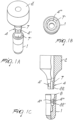
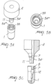
- a dental implant 1 preferably a dental implant having an external thread for insertion into a bone tissue, an abutment or secondary part 2 and a threaded fastener screw 3 forming together a dental implant system.
- the threaded fastener screw 3 is preferably axially hold in the abutment, as best seen in Fig. 1D .
- the abutment 2 is provided with guiding and lock means implemented as a first conically tapered section 7, followed, in a further apical position, by a second substantially non-tapered section 4 with protrusions 4' extending in an axial direction of the abutment 2 and followed, in further remote apical position, by a third substantially circular cylindrical section 22.
- the number of protrusions shown in figures 1A through 1E is equal to eight. This results in a substantially octagonal cross-section of the second non-tapered section 4. Nevertheless, the person skilled in the art will appreciate that the number of protrusions may be varied as need be to adjust the number of relative positions between the dental implant 1 and the abutment 2. Also the shape of the protrusions 4' may be varied, such that the resulting cross-section of the respective abutment section is not necessarily octagonal.
- the axial extension of second section 4 is about twice the axial extension of the third section 22. Further, it has been found that it is particularly advantageous if the axial extension of the first section 7 is approximately equal to the overall axial extension of the second 4 and third 22 sections taken together. Therefore, the user is provided with a longer insertion path and consequently with a better feedback when assembling the abutment to the dental implant.
- the fastening (or threading) of the screw 3 to a dental implant is only possible once the second section 4 along with the third section 22 are fully inserted into their complementary sections of the dental implant, as will be described hereinafter. In this way a wedging of the screw can be avoided.
- the taper of the first section 7 with respect to the axis of the abutment 2 is in the order of about 6° to about 10°, preferably about 7° to about 9° and most preferably about 8° such that sealing and stability requirements of the coupling between the dental implant and the abutment are met.
- the axial extension of the first section 7 is preferably, as explained, in the order of about the overall axial length of the second 4 and third 22 sections taken together. The latter also further improves the sealing and stability characteristic of the dental implant system of the present invention.
- the dental implant 1 is provided with guiding and lock means that are complementary to the guiding and lock means of the abutment 2, namely a first conically tapered section 7' matching the first conically tapered section 7 of the abutment 2, a second substantially non-tapered section 4" with grooves 4′′′ adapted for receiving the second substantially non-tapered section 4 and the protrusions 4' of the abutment 2, and a third substantially circular cylindrical section 22' adapted for receiving the third section 22 of the abutment.
- first 7', second 4", and third 22' sections of the dental implant 1 are, as set forth above, complementary to the first 7, second 4, and third 22 sections of the abutment 2 as regards shape, extension, taper angle etc., the detailed description thereof will be omitted for the sake of avoiding repetitions. Nonetheless, the person skilled in the art will appreciate that the number of protrusions must not equate the number of grooves, as also apparent from some of the embodiments described hereinbelow.
- the shoulder 8 of the dental implant 1 is free of grooves and the grooves/protrusions providing for the anti-rotation lock between the dental implant 1 and the abutment 2 are displaced from the shoulder 8. Therefore, the sealing characteristics of the dental implant system at the interface between the dental implant and the abutment are not impaired and the sterility thereof is maintained. In addition, the jamming of the protrusions 4' is avoided upon the insertion of the abutment 2 into the dental implant 1 due to presence of the first tapered sections 7 and 7'.
- the third sections 22 and 22' of the abutment 2 and dental implant 1, respectively, provide for a guiding function that facilitates the insertion of the abutment 2 into the dental implant 1.
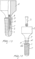
- FIG. 2C A second embodiment of the present invention is described with regard to figures 2A through 2C wherein features similar to those of the first embodiment of the invention are designated by the same reference numerals, and therefore the description thereof will be omitted to the extent of the overlap with the first embodiment of the invention.
- the second and the third sections of the abutment 2 are replaced by a protrusion 24' that is provided apically adjacent to the first section 7 thereof.
- a protrusion 24' that is provided apically adjacent to the first section 7 thereof.
- the abutment is also shown in an inverted view in Fig. 2A .
- the second and third sections are, in turn, replaced by an annular platform 5 with grooves 24′′′ which provide for a rosetted appearance to the guiding and lock means of the dental implant 1. While four grooves 24′′′ are shown in figures 2A and 2B , the person skilled in the art will readily understand that their number can be varied as need be, for instance to adjust the number of relative positions between dental implant and abutment.
- the improved handling of the second embodiment of the invention is achieved by placing the abutment 2 with its protrusion 24' on the annular platform 5 of the dental implant 1 in an intermediate position. In this position it is not possible to tighten the fastener screw 3. Therefore, an improved jamming safety is provided to the abutment. Tightening of the fastener screw 3 is only possible if the protrusion 24' is rotated until it is brought in registration with one of the grooves 24′′′ and fully penetrates it. In this way, the second embodiment of the invention provides for an advantageous implementation of the guiding function that facilitates the insertion of the abutment 2 into the dental implant 1.
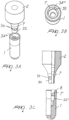
- a third embodiment of the present invention is described with regard to figures 3A through 3C wherein features similar to those of the first embodiment of the invention are designated by the same reference numerals, and therefore the description thereof will be omitted to the extent of the overlap with the first embodiment of the invention.
- the second section 34 is implemented with a substantially octagonal cross-section, with four straight sides connected by four interposed protruding sides, each of the protruding sides having preferably a curved shape.
- the cross-section resembles to a square with rounded edges.
- the substantially cylindrical third section 22 of the abutment 2 is similar to the third section 22 of the abutment of the first embodiment.
- the second section of the dental implant 1 is replaced yet again by a platform 35 with four grooves 34′′′ which provide for the above described square appearance with rounded edges to the guiding and lock means of the dental implant 1.
- the outline or the cross-section of the platform 35 and the grooves 34′′′ of the dental implant is complementary to the outline or cross-section of the second section 34 of the abutment 2.
- the third section 22' of the dental implant is complementary to the third section 22 of the abutment 2.
- the improved handling of the third embodiment of the present invention is achieved by placing the abutment 2 with its second section 34 (forming the square outline with rounded edges) on the platform 35 of the dental implant 1 in an intermediate position, such that the straight sides of the second section 34 of the abutment 2 rest on the platform 35 of the dental implant. In this position it is not possible to tighten the fastener screw 3. Therefore, an improved jamming safety is provided to the abutment. Tightening of the fastener screw 3 is only possible if the second section 34 of the abutment 2 is rotated into registration with the grooves 34′′′.
- the third embodiment of the present invention provides for an advantageous implementation of the guiding function that facilitates the insertion of the abutment 2 into the dental implant 1. Furthermore, the guiding function is enhanced by the presence of the respective third sections on the abut-ment and dental implant.
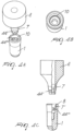
- the abutment 2 is provided with eight protrusion 44' (forming a substantially octagonal outline) while the dental implant 1 is provided with eight matching grooves 44′′′ (also forming a substantially octagonal outline) and adapted to receive the protrusions 44'.
- the number of protrusions and of the matching grooves can be varied as need be.
- the grooves 44′′′ of the dental implant 1 serve only as (rotational) positioning or re-positioning elements and are not subjected to stress due to force transmission.
- a fifth embodiment of the present invention is described with regard to figures 5A through 5C wherein features similar to those of the first embodiment of the invention are designated by the same reference numerals, and therefore the description thereof will be omitted to the extent of the overlap with the first embodiment of the invention.
- the abutment 2 is provided with three protrusions 54' (forming a substantially triangular outline) while the dental implant 1 is provided with three matching grooves 54′′′ (also forming a substantially triangular outline) and adapted to receive the protrusions 54'.
- Such substantially triangular outline allows a better force transmission.
- annular platform 55 surrounding the grooves 54′′′. Accordingly, in a similar manner to the second embodiment an improved jamming safety is provided to the abutment 2, as the abutment 2 is held in an intermediate position on the annular platform 55 until the protrusions 54' are rotated into registration with the grooves 54′′′ such that the abutment 2 fully penetrates the dental implant 1 and may be firmly fastened by the fastener screw 3 thereto.
- a particular feature of the fifth embodiment is the extended cylindrical third section designated by reference numeral 11 provided at the apical end of the abutment 2 adjacent to the second non-tapered section, the extended cylindrical third section 11 providing, in conjunction with a matching third section 12 in the dental implant 1, for a better support and guiding of the abutment 2.
- the axial extension of the extended third section 11 of the abutment is such that the ratio thereof to the axial extension of the second section of the abutment 2 is from about 1.4 to 1.7 and more preferably 1.6.
- the axial extension of the first section of the abutment is about one half of the axial extension second section thereof.
- a sixth embodiment of the present invention is described with regard to figures 6A through 6C wherein features similar to those of the first embodiment of the invention are designated by the same reference numerals, and therefore the description thereof will be omitted to the extent of the overlap with the first embodiment of the invention.
- the abutment 2 is provided with one single protrusion 64' while the dental implant 1 is provided with a plurality (e.g. four) matching grooves 64" and adapted to receive the protrusion 64'.
- annular platform 65 interposed between the grooves 64′′′.
- an improved jamming safety is provided to the abutment 2, as the abutment 2 is held in an intermediate position on the annular platform 65 until the protrusion 64' is rotated into registration with one of the grooves 64′′′ such that the abutment 2 fully penetrates the dental implant 1.
- the guiding and support function in the sixth embodiment is enhanced by the presence of the respective extended third sections on the abutment and dental implant, wherein the sections are devised to have an axial extension similar to that of the fifth embodiment.
- the dental implant and abutment of the invention can be manufactured from ceramics, metal (in particular titan) and combinations thereof.
Claims (3)
- Eine Kombination aus einem Zahnimplantat (1), einem Abutment (2) und einer mit einem Gewinde versehenen Schraube (3) zur Verwendung in einem Zahnimplantatsystem,
wobei das Zahnimplantat (1) mit einem Führungs- und Verriegelungsmittel zur Verbindung des Zahnimplantats (1) mit dem Abutment ausgestattet ist, wobei das Führungs- und Verriegelungsmittel Folgendes einschließt:einen ersten kegelförmig verjüngten Abschnitt (7') undeinen zweiten nicht verjüngten Abschnitt (4"), der apikal direkt angrenzend an den ersten Abschnitt (7') angeordnet ist, wobei der zweite Abschnitt (4") mit einem Anti-Rotationsmittel (4‴; 24‴; 34‴; 54‴; 64‴) ausgestattet ist,wobei das Anti-Rotationsmittel (4‴; 24‴; 34‴; 54‴; 64‴) des zweiten Abschnitts (4") eine Oberfläche einschließt, die sich radial mit Bezug auf die Achse des Zahnimplantats (1) erstreckt und ausgebildet ist, um mit dem Abutment (2) zusammenzuwirken, um so dem Abutment (2) beim Einsetzen in das Implantat (1) eine radiale Führung bereitzustellen, unddas Abutment (2) mit einem Führungs- und Verriegelungsmittel zur Verbindung des Abutments (2) mit dem Zahnimplantat (1) ausgestattet ist, wobei das Führungs- und Verriegelungsmittel Folgendes einschließt:einen ersten kegelförmig verjüngten Abschnitt (7) undeinen zweiten nicht verjüngten Abschnitt (4), der apikal direkt angrenzend an den ersten Abschnitt (7) angeordnet ist, wobei der zweite Abschnitt (4) mit einem Anti-Rotationsmittel (4'; 24'; 34'; 54', 64') ausgestattet ist,wobei das Anti-Rotationsmittel (4'; 24'; 34; 54', 64') des zweiten Abschnitts (4) eine Oberfläche einschließt, die sich radial mit Bezug auf die Achse des Abutments (2) erstreckt und ausgebildet ist, um mit dem Zahnimplantat (1) zusammenzuwirken, um so dem Abutment (2) beim Einsetzen in das Implantat (1) eine radiale Führung bereitzustellen, wobei das Abutment (2) ausgebildet ist, um die mit dem Gewinde versehene Schraube (3) zur Befestigung des Abutments (2) am Zahnimplantat (1) axial zu halten, undwobei eine axiale Gesamtlänge der ersten und zweiten Abschnitte (7, 4) des Abutments (2) und die Position der mit dem Gewinde versehenen Schraube (3) innerhalb des Abutments (2) vor Befestigung desselben am Zahnimplantat (1) so gewählt sind, dass die Befestigung der mit dem Gewinde versehenen Schraube (3) an einem Gewindeabschnitt des Zahnimplantats (1) nur dann möglich ist, wenn die ersten und zweiten Abschnitte (7, 4) des Abutments (2) vollständig in ihre Gegenstücke (7', 4") am Zahnimplantat (1) eingesetzt sind. - Die Kombination gemäß Anspruch 1, wobei die Führungs- und Verriegelungsmittel des Implantats (1) und des Abutments (2) jeweils weiter einen dritten kreiszylindrischen Abschnitt (22', 22; 12, 11) einschließen, der apikal angrenzend an die jeweiligen zweiten Abschnitte (4", 4) des Implantats (1) und des Abutments (2) angeordnet ist, um dem Abutment (2) beim Einsetzen desselben in das Zahnimplantat (1) eine axiale Führung bereitzustellen.
- Die Kombination gemäß Anspruch 1 oder 2, wobei die Verjüngung des ersten Abschnitts (7) des Abutments (2) mit Bezug auf die Achse des Abutments (2) in der Größenordnung von ungefähr 6° bis ungefähr 10°, vorzugsweise ungefähr 7° bis ungefähr 9° und am meisten bevorzugt ungefähr 8° liegt und die Verjüngung des ersten Abschnitts (7') des Zahnimplantats (1) mit Bezug auf die Achse desselben entsprechend in der Größenordnung von ungefähr 6° bis ungefähr 10°, vorzugsweise ungefähr 7° bis ungefähr 9° und am meisten bevorzugt ungefähr 8° liegt.
Priority Applications (2)
| Application Number | Priority Date | Filing Date | Title |
|---|---|---|---|
| EP16169365.0A EP3115018B1 (de) | 2005-06-03 | 2005-06-03 | Verbesserte kupplung für mehrteiliges zahnimplantatsystem |
| EP24156890.6A EP4356870A2 (de) | 2005-06-03 | 2005-06-03 | Verbesserte kupplung für ein mehrteiliges zahnimplantatsystem |
Applications Claiming Priority (2)
| Application Number | Priority Date | Filing Date | Title |
|---|---|---|---|
| EP05104832A EP1728486A1 (de) | 2005-06-03 | 2005-06-03 | Kupplung für ein mehrteiliges Zahnimplantatsystem |
| EP16169365.0A EP3115018B1 (de) | 2005-06-03 | 2005-06-03 | Verbesserte kupplung für mehrteiliges zahnimplantatsystem |
Related Parent Applications (1)
| Application Number | Title | Priority Date | Filing Date |
|---|---|---|---|
| EP05104832A Division EP1728486A1 (de) | 2005-06-03 | 2005-06-03 | Kupplung für ein mehrteiliges Zahnimplantatsystem |
Related Child Applications (1)
| Application Number | Title | Priority Date | Filing Date |
|---|---|---|---|
| EP24156890.6A Division EP4356870A2 (de) | 2005-06-03 | 2005-06-03 | Verbesserte kupplung für ein mehrteiliges zahnimplantatsystem |
Publications (2)
| Publication Number | Publication Date |
|---|---|
| EP3115018A1 EP3115018A1 (de) | 2017-01-11 |
| EP3115018B1 true EP3115018B1 (de) | 2024-02-14 |
Family
ID=35134777
Family Applications (5)
| Application Number | Title | Priority Date | Filing Date |
|---|---|---|---|
| EP05104832A Withdrawn EP1728486A1 (de) | 2005-06-03 | 2005-06-03 | Kupplung für ein mehrteiliges Zahnimplantatsystem |
| EP16169365.0A Active EP3115018B1 (de) | 2005-06-03 | 2005-06-03 | Verbesserte kupplung für mehrteiliges zahnimplantatsystem |
| EP10183177.4A Active EP2260788B1 (de) | 2005-06-03 | 2005-06-03 | Verbesserte Kupplung für mehrteiliges Zahnimplantatsystem |
| EP09167539.7A Revoked EP2119414B1 (de) | 2005-06-03 | 2005-06-03 | Kupplung für mehrteiliges Zahnimplantatsystem |
| EP24156890.6A Pending EP4356870A2 (de) | 2005-06-03 | 2005-06-03 | Verbesserte kupplung für ein mehrteiliges zahnimplantatsystem |
Family Applications Before (1)
| Application Number | Title | Priority Date | Filing Date |
|---|---|---|---|
| EP05104832A Withdrawn EP1728486A1 (de) | 2005-06-03 | 2005-06-03 | Kupplung für ein mehrteiliges Zahnimplantatsystem |
Family Applications After (3)
| Application Number | Title | Priority Date | Filing Date |
|---|---|---|---|
| EP10183177.4A Active EP2260788B1 (de) | 2005-06-03 | 2005-06-03 | Verbesserte Kupplung für mehrteiliges Zahnimplantatsystem |
| EP09167539.7A Revoked EP2119414B1 (de) | 2005-06-03 | 2005-06-03 | Kupplung für mehrteiliges Zahnimplantatsystem |
| EP24156890.6A Pending EP4356870A2 (de) | 2005-06-03 | 2005-06-03 | Verbesserte kupplung für ein mehrteiliges zahnimplantatsystem |
Country Status (11)
| Country | Link |
|---|---|
| US (3) | US8408904B2 (de) |
| EP (5) | EP1728486A1 (de) |
| JP (2) | JP4942742B2 (de) |
| KR (1) | KR101239565B1 (de) |
| CN (1) | CN101188982B (de) |
| AU (1) | AU2006254357B2 (de) |
| CA (1) | CA2607117A1 (de) |
| DK (1) | DK2119414T3 (de) |
| ES (1) | ES2415737T3 (de) |
| WO (1) | WO2006128620A2 (de) |
| ZA (2) | ZA200711030B (de) |
Families Citing this family (78)
| Publication number | Priority date | Publication date | Assignee | Title |
|---|---|---|---|---|
| SE520756C2 (sv) | 2001-12-21 | 2003-08-19 | Nobel Biocare Ab | Förfarande för att åstadkomma ytstruktur på implantat samt sådant implantat |
| SE523395C2 (sv) | 2001-12-21 | 2004-04-13 | Nobel Biocare Ab | Implantat och förfarande och system för tillhandahållande av sådant implantat |
| IL156033A0 (en) | 2003-05-21 | 2004-03-28 | Ophir Fromovich Ophir Fromovic | Dental implant |
| EP1728486A1 (de) | 2005-06-03 | 2006-12-06 | Straumann Holding AG | Kupplung für ein mehrteiliges Zahnimplantatsystem |
| US8038442B2 (en) * | 2007-04-23 | 2011-10-18 | Nobel Biocare Services Ag | Dental implant and dental component connection |
| US7806693B2 (en) | 2007-04-23 | 2010-10-05 | Nobel Biocare Services Ag | Dental implant |
| FR2915674A1 (fr) * | 2007-05-11 | 2008-11-07 | Gilbert Ouaknine | Vis maxillo faciale pour implants dentaires |
| FR2915676A1 (fr) * | 2007-05-11 | 2008-11-07 | Gilbert Ouaknine | Implant dentaire |
| WO2008145869A2 (fr) * | 2007-05-04 | 2008-12-04 | Gilbert Ouaknine | Dispositifs pour implants, faux moignons, obturateurs, stabilisateurs, en implantologie dentaire |
| WO2009009910A1 (de) | 2007-07-16 | 2009-01-22 | Dentalpoint Ag | Zahnimplantat |
| EP2106767A1 (de) * | 2008-03-31 | 2009-10-07 | Ziterion GmbH | Zweiteiliges Zahnimplantat |
| ES2344240B1 (es) * | 2008-06-20 | 2011-06-13 | Biotechnology Institute, I Mas D, S.L. | Herramienta para permitir la extraccion de un implante. |
| CN101732097A (zh) * | 2008-11-19 | 2010-06-16 | 威海威高生物技术有限公司 | 圆锥面加矩形键结构的口腔种植体 |
| CH700097A1 (de) | 2008-12-10 | 2010-06-15 | Straumann Holding Ag | Instrument zum Lösen eines Schraubenstumpfes einer Verbindungsschraube eines Zahnimplantats. |
| IL196872A0 (en) | 2009-02-03 | 2009-11-18 | Daniel Baruc | Dental abutment with indentation for inhibition of crestal bone remodeling |
| DK2215989T3 (da) | 2009-02-05 | 2019-09-23 | Ivoclar Vivadent Ag | Konstruktionsdel til et tandimplantat |
| FR2945205B1 (fr) * | 2009-05-11 | 2012-07-13 | Rech S Et De Fabrication Serf Soc Et | Ensemble prothetique dentaire. |
| DE102009057754B4 (de) | 2009-12-10 | 2016-01-21 | Cera M Gmbh | Zahnimplantat |
| EP2347729A1 (de) * | 2010-01-21 | 2011-07-27 | Camlog Biotechnologies AG | Zahnimplantat, Abutment für ein Zahnimplantat und Kombination davon sowie ein Implantations-Set |
| AU2015207851B2 (en) * | 2010-01-21 | 2017-03-02 | Camlog Biotechnologies Ag | Dental implant, abutment for a dental implant and combination thereof |
| PL2566413T3 (pl) | 2010-05-05 | 2017-07-31 | Holger Zipprich | Implant stomatologiczny |
| WO2012003502A2 (en) | 2010-07-02 | 2012-01-05 | University Of Florida Research Foundation, Inc. | Bioresorbable metal alloy and implants made of same |
| US11491257B2 (en) | 2010-07-02 | 2022-11-08 | University Of Florida Research Foundation, Inc. | Bioresorbable metal alloy and implants |
| EP2444023A1 (de) * | 2010-10-20 | 2012-04-25 | Astra Tech AB | Zahnkomponente, Zahnimplantatfixierung und Zahnimplantatanordnung |
| EP2444024A1 (de) * | 2010-10-20 | 2012-04-25 | Astra Tech AB | Zahnimplantatfixierung, Zahnkomponente und Zahnimplantatanordnung |
| CN101947139B (zh) * | 2010-10-21 | 2013-10-23 | 赵大国 | 一种仿生牙种植体及其基台和子根 |
| DE102010051176A1 (de) | 2010-11-15 | 2012-05-16 | Urs Brodbeck | Dental-Implantatsystem und Verfahren zur Herstellung eines Dental-Implantatsystems |
| CH704382A1 (de) | 2011-01-25 | 2012-07-31 | Dentalpoint Ag | Zahnersatz-System. |
| DE102011009906A1 (de) | 2011-01-31 | 2012-08-02 | Holger Zipprich | Dental- Implantatsystem |
| FR2972625B1 (fr) † | 2011-03-15 | 2014-02-28 | Biotech Internat | Implant dentaire |
| EP2502600A1 (de) * | 2011-03-21 | 2012-09-26 | Biodenta Swiss AG | Dental-Implantatsystem |
| USD721809S1 (en) | 2011-05-13 | 2015-01-27 | Astra Tech Ab | Dental implant |
| KR101093512B1 (ko) * | 2011-05-26 | 2011-12-13 | 염명희 | 임플란트용 어버트먼트 소재 |
| JP2015504315A (ja) * | 2011-08-12 | 2015-02-12 | ワン・ジェ−ウォンWANG, Je−Won | 多角度に製作されるコアクラウンの収容が可能であり、キャップを取り付けるとヒーリングアバットメントの機能を行うアバットメントと、それを用いたインプラント補綴物の製造方法及びインプラント手術方法 |
| EP2570097A1 (de) | 2011-09-14 | 2013-03-20 | Dentsply IH AB | Zahnkomponente, Zahnimplantatanker und Zahnimplantat |
| EP2570095A1 (de) | 2011-09-14 | 2013-03-20 | Dentsply IH AB | Zahnkomponente und Zahnimplantat |
| DE102012201092B4 (de) * | 2012-01-25 | 2019-07-11 | Ivoclar Vivadent Ag | Zahntechnisches Implantatsystem |
| US20130236855A1 (en) * | 2012-03-08 | 2013-09-12 | James R. Glidewell Dental Ceramics, Inc. | Premanufactured ceramic dental implant abutments for mating ceramic prosthetic build-up construction |
| EP2653131B1 (de) * | 2012-04-19 | 2018-02-28 | Dentsply IH AB | Zahnimplantatset |
| DE102012012494B4 (de) * | 2012-06-21 | 2016-02-11 | FairImplant GmbH | Zweiteiliges Dentalimplantat |
| GB201212125D0 (en) * | 2012-07-09 | 2012-08-22 | Nobel Biocare Services Ag | Abutment system and dental methods |
| TR201300434A2 (tr) * | 2013-01-11 | 2014-05-21 | Ibrahim Serce | Bir abutment üretim sistemi ve yöntemi. |
| DE102013102402B4 (de) * | 2013-03-11 | 2018-10-11 | Bruno Spindler | Fräsrohling für einen abutmentaufsatz |
| CN105208965B (zh) * | 2013-03-15 | 2018-10-16 | 捷迈齿科有限公司 | 具有改进假体分界面的牙植入物 |
| USD731655S1 (en) | 2013-03-15 | 2015-06-09 | Benedict Lui | Dental implant abutment |
| US10266922B2 (en) | 2013-07-03 | 2019-04-23 | University Of Florida Research Foundation Inc. | Biodegradable magnesium alloys, methods of manufacture thereof and articles comprising the same |
| ES2809470T3 (es) * | 2013-07-26 | 2021-03-04 | Sic Invent Ag | Implante dental, pilar, sistema de implante y juego de implantación |
| TWM469054U (zh) * | 2013-09-11 | 2014-01-01 | Shi-Zheng Wen | 人工植體組件 |
| USD732169S1 (en) | 2013-09-16 | 2015-06-16 | Benedict Lui | Dental implant abutment |
| GB2519296A (en) | 2013-10-15 | 2015-04-22 | Nobel Biocare Services Ag | Dental implant replica |
| US9795427B2 (en) | 2013-11-05 | 2017-10-24 | University Of Florida Research Foundation, Inc. | Articles comprising reversibly attached screws comprising a biodegradable composition, methods of manufacture thereof and uses thereof |
| DE102014118723A1 (de) * | 2013-12-17 | 2015-06-18 | Epiphanostics GmbH | Enossales Einzelzahnimplantat |
| IL230438A (en) * | 2014-01-13 | 2015-07-30 | Boris Fridzon | Connection kit for dental implant |
| IL230833A0 (en) * | 2014-02-05 | 2014-09-30 | Ophir Fromovich | bone graft |
| ES2568515B1 (es) | 2014-10-29 | 2017-02-21 | Vogul, S.L.U. | Implante dental |
| BR102014031426B1 (pt) | 2014-12-15 | 2018-07-24 | Jjgc Ind E Comercio De Materiais Dentarios S/A | implante |
| CL2015001657S1 (es) | 2014-12-15 | 2016-09-02 | Jjgc Indústria E Comércio De Materiais Dentários S A | Configuracion aplicada a implante oseo. |
| WO2016118444A1 (en) | 2015-01-23 | 2016-07-28 | University Of Florida Research Foundation, Inc. | Radiation shielding and mitigating alloys, methods of manufacture thereof and articles comprising the same |
| DE102015002948A1 (de) | 2015-03-10 | 2016-09-15 | Straumann Holding Ag | System zum Modellieren eines implantatgestützten Zahnersatzelements und seine Verwendung |
| EP3095409A1 (de) * | 2015-05-21 | 2016-11-23 | Epiphanostics GmbH | Insertionsset für ein enossales einzelzahnimplantat |
| CH711169A1 (de) * | 2015-06-08 | 2016-12-15 | Dentalpoint Ag | Zahnersatzsystem. |
| WO2017027860A1 (en) * | 2015-08-12 | 2017-02-16 | Wang Chan Qian | A margin ring and method of making dental crown using the margin ring |
| DE102015121658A1 (de) * | 2015-12-11 | 2017-06-14 | Aesculap Ag | Künstliches Gelenkimplantat und Hüftgelenkendoprothese |
| US10987201B2 (en) | 2016-02-23 | 2021-04-27 | Paltop Advanced Dental Solutions Ltd. | Dental implant |
| EP3443931A4 (de) * | 2016-04-12 | 2019-11-27 | Nantoh.Co., Ltd | Befestigung und implantat |
| BR102016010184B1 (pt) | 2016-05-05 | 2020-10-27 | Jjgc Indústria E Comércio De Materiais Dentários S.A. | conjunto protético e processo para produção do mesmo |
| US10149868B2 (en) * | 2016-05-31 | 2018-12-11 | Tco Co., Ltd. | Use of Streptococcus thermophilis TCI633 in treating arthritis |
| SE1651462A1 (en) | 2016-11-08 | 2017-10-31 | Integrum Ab | Anchoring system for attaching a prosthesis to a human body |
| RU2017102870A (ru) | 2017-01-27 | 2018-07-27 | Никита Сергеевич Черновол | Дентальный имплантат |
| US10792132B2 (en) | 2017-03-20 | 2020-10-06 | Paltop Advanced Dental Solutions Ltd. | Implant placement key |
| JP7299870B2 (ja) | 2017-03-20 | 2023-06-28 | ストラウマン ホールディング アーゲー | インプラントシステム |
| RU2695772C2 (ru) | 2017-07-17 | 2019-07-25 | Никита Сергеевич Черновол | Набор имплантатов для имплантации |
| ES2663539B2 (es) * | 2017-12-05 | 2018-07-12 | Julián CUESTA GARCIA | Sistema de implante dental altamente autorroscante con conexión híbrida y bloqueo de doble cono paralelo entre el pilar protético, el implante y el tornillo interno. |
| US10987196B2 (en) | 2018-06-27 | 2021-04-27 | Paltop Advanced Dental Solutions Ltd. | Drill guide |
| WO2020053641A1 (en) * | 2018-09-15 | 2020-03-19 | Vivek Kumar | Multiple platform dental implant (mpdi) |
| CN110368114B (zh) * | 2019-08-05 | 2021-06-22 | 四川大学 | 用预成嵌体封闭牙种植上部修复螺丝孔的数字化设计方法 |
| CN110547887B (zh) * | 2019-09-16 | 2021-06-11 | 青岛大学附属医院 | 一种口腔种植体装置 |
| BR102020022937A2 (pt) * | 2020-11-10 | 2022-05-24 | Jjgc Indústria E Comércio De Materiais Dentários S.A. | Sistema de componentes e implantes dentários contendo configurações geométricas que apenas permitem montagem entre peças correspondentes |
Citations (5)
| Publication number | Priority date | Publication date | Assignee | Title |
|---|---|---|---|---|
| WO1993008762A1 (fr) | 1991-11-07 | 1993-05-13 | Yeung Jean Claude | Implant dentaire |
| AT400804B (de) | 1994-10-10 | 1996-03-25 | Mke Metall Kunststoffwaren | Implantat |
| US20020031748A1 (en) | 2000-09-12 | 2002-03-14 | Vincenzo Crudo | Implant for fixing dental prostheses |
| DE10315399A1 (de) | 2003-02-21 | 2004-09-02 | Schröder, Ralf, Dr. | Zahnimplantat mit Grundkörper und Implantatpfosten sowie Grundkörper und Implantatpfosten für ein Zahnimplantat |
| DE10340059A1 (de) | 2003-07-24 | 2005-02-10 | Schröder, Ralf, Dr. | Zahnimplantat, insbesondere Grundkörper und Aufbauteil eines Zahnimplantats |
Family Cites Families (29)
| Publication number | Priority date | Publication date | Assignee | Title |
|---|---|---|---|---|
| IL99411A (en) | 1990-09-08 | 1996-01-19 | Eberle Medizintech Elemente | Anus implant of a single tooth with torsional delay |
| US5281140A (en) | 1991-01-02 | 1994-01-25 | Core-Vent Corporation | Multi-part, multi-positionable abutment for use with dental implants |
| US5195852A (en) | 1991-11-18 | 1993-03-23 | Malugani Jack R | Vacuum pick-up nozzle with air boost manifold |
| IL113726A (en) * | 1994-06-03 | 1998-04-05 | Straumann Inst Ag | A device for the production of dentures and a method for its production |
| US5733124A (en) * | 1995-02-21 | 1998-03-31 | Kwan; Norman Ho-Kwong | Dental implant system |
| NL9500393A (nl) * | 1995-02-28 | 1996-10-01 | Accius Bv | Inrichting voor het bevestigen van een element aan een menslijk of dierlijk lichaam. |
| KR19990014953A (ko) * | 1995-05-25 | 1999-02-25 | 키어스 디 비티 | 회전 방지 연결 기구 |
| DE19534979C1 (de) | 1995-09-20 | 1997-01-09 | Imz Fertigung Vertrieb | Enossales Einzelzahnimplantat mit Verdrehsicherung |
| WO1997014371A1 (de) | 1995-10-13 | 1997-04-24 | Institut Straumann Ag | Verbindungsanordnung zwischen einem implantat und einem abutment |
| DE19633570C1 (de) | 1996-08-21 | 1998-01-02 | Imz Fertigung Vertrieb | Enossales Einzelzahnimplantat mit Verdrehsicherung und Stanzwerkzeug sowie Positionierhilfe zur Fertigstellung eines solchen Einzelzahnimplantats |
| DE19713012C2 (de) | 1997-03-27 | 2003-12-04 | Friadent Gmbh | Dentalimplantat |
| US6157733A (en) * | 1997-04-18 | 2000-12-05 | At&T Corp. | Integration of monocular cues to improve depth perception |
| BR9809683A (pt) * | 1997-05-24 | 2000-10-03 | Friadent Gmbh | Implante dentário e dispositivo com um implante dentário |
| US6663388B1 (en) | 1998-12-28 | 2003-12-16 | Institut Straumann Ag | Connection between a dental implant and an abutment |
| ATE424781T1 (de) | 2000-01-04 | 2009-03-15 | Straumann Holding Ag | Enossales dentalimplantat |
| GB0108551D0 (en) | 2001-04-05 | 2001-05-23 | Osseobiotek Ltd | Implant |
| US6824386B2 (en) | 2001-11-01 | 2004-11-30 | Astra Tech Ab | Components for improved impression making |
| WO2003047455A1 (en) | 2001-12-03 | 2003-06-12 | Cottrell Richard D | Modified dental implant fixture |
| EP1396236A1 (de) * | 2002-09-06 | 2004-03-10 | Leone S.p.A. | Ein Dentalimplantat und Kit dazu |
| IL190642A (en) * | 2002-11-13 | 2011-06-30 | Biomet 3I Llc | Dental implant system |
| EP1626670A2 (de) | 2003-02-21 | 2006-02-22 | Ralf Schröder | Zahnimplantat mit grundkörper und implantatpfosten sowie grundkörper und implantatpfosten für ein zahnimplantat |
| DE10315563A1 (de) * | 2003-04-05 | 2004-10-28 | Bego Medical Ag | Verfahren zur Herstellung von Implantataufbauten für Dentalimplantate sowie Implantataufbau für Dentalimplantat |
| DE10329207A1 (de) | 2003-06-28 | 2005-01-13 | Ralf Dr. Schröder | Grundkörper für ein Zahnimplantat, Zahnimplantat mit Grundkörper, Implantatpfosten eines Zahnimplantats zur Einführung in den Grundkörper, Zahnimplantat mit Grundkörper und Implantatpfosten sowie Kronenkörper für den Implantatpfosten oder das Zahnimplantat und Verpackung für Zahnimplantat |
| AR043256A1 (es) * | 2004-02-20 | 2005-07-20 | Odontit S A | Una disposicion de implante dental integrado al hueso para sostener una protesis dental |
| US7249949B2 (en) | 2004-06-29 | 2007-07-31 | Lifecore Biomedical, Inc. | Internal connection dental implant |
| DE202005000208U1 (de) * | 2005-01-07 | 2005-07-07 | Lippe, Rainer | In einem menschlichen Kiefer einschraubbares Dentalimplantat zur Aufnahme und Fixierung eines Zahnersatzes |
| US7785107B2 (en) * | 2005-02-01 | 2010-08-31 | Niznick Gerald A | Multi-functional fixture mount |
| ITTO20050241A1 (it) * | 2005-04-12 | 2006-10-13 | Claudio Gatti | Impianto dentario intraosseo. |
| EP1728486A1 (de) * | 2005-06-03 | 2006-12-06 | Straumann Holding AG | Kupplung für ein mehrteiliges Zahnimplantatsystem |
-
2005
- 2005-06-03 EP EP05104832A patent/EP1728486A1/de not_active Withdrawn
- 2005-06-03 EP EP16169365.0A patent/EP3115018B1/de active Active
- 2005-06-03 EP EP10183177.4A patent/EP2260788B1/de active Active
- 2005-06-03 EP EP09167539.7A patent/EP2119414B1/de not_active Revoked
- 2005-06-03 DK DK09167539.7T patent/DK2119414T3/da active
- 2005-06-03 ES ES09167539T patent/ES2415737T3/es active Active
- 2005-06-03 EP EP24156890.6A patent/EP4356870A2/de active Pending
-
2006
- 2006-05-23 CA CA002607117A patent/CA2607117A1/en not_active Abandoned
- 2006-05-23 KR KR1020087000121A patent/KR101239565B1/ko active IP Right Grant
- 2006-05-23 WO PCT/EP2006/004919 patent/WO2006128620A2/en active Application Filing
- 2006-05-23 JP JP2008513979A patent/JP4942742B2/ja active Active
- 2006-05-23 AU AU2006254357A patent/AU2006254357B2/en active Active
- 2006-05-23 US US11/921,480 patent/US8408904B2/en active Active
- 2006-05-23 CN CN2006800197259A patent/CN101188982B/zh active Active
-
2007
- 2007-05-23 ZA ZA200711030A patent/ZA200711030B/xx unknown
-
2009
- 2009-03-17 ZA ZA200901872A patent/ZA200901872B/en unknown
-
2011
- 2011-12-13 JP JP2011272508A patent/JP5475748B2/ja active Active
-
2013
- 2013-03-05 US US13/785,702 patent/US8968002B2/en active Active
-
2015
- 2015-01-26 US US14/604,966 patent/US11779439B2/en active Active
Patent Citations (5)
| Publication number | Priority date | Publication date | Assignee | Title |
|---|---|---|---|---|
| WO1993008762A1 (fr) | 1991-11-07 | 1993-05-13 | Yeung Jean Claude | Implant dentaire |
| AT400804B (de) | 1994-10-10 | 1996-03-25 | Mke Metall Kunststoffwaren | Implantat |
| US20020031748A1 (en) | 2000-09-12 | 2002-03-14 | Vincenzo Crudo | Implant for fixing dental prostheses |
| DE10315399A1 (de) | 2003-02-21 | 2004-09-02 | Schröder, Ralf, Dr. | Zahnimplantat mit Grundkörper und Implantatpfosten sowie Grundkörper und Implantatpfosten für ein Zahnimplantat |
| DE10340059A1 (de) | 2003-07-24 | 2005-02-10 | Schröder, Ralf, Dr. | Zahnimplantat, insbesondere Grundkörper und Aufbauteil eines Zahnimplantats |
Also Published As
| Publication number | Publication date |
|---|---|
| ZA200901872B (en) | 2010-01-27 |
| KR20080012404A (ko) | 2008-02-11 |
| WO2006128620A2 (en) | 2006-12-07 |
| AU2006254357B2 (en) | 2011-08-04 |
| EP3115018A1 (de) | 2017-01-11 |
| US8968002B2 (en) | 2015-03-03 |
| EP2119414B1 (de) | 2013-04-24 |
| CN101188982B (zh) | 2011-09-21 |
| WO2006128620A3 (en) | 2007-04-19 |
| EP2260788B1 (de) | 2024-03-13 |
| US20150157427A1 (en) | 2015-06-11 |
| JP2012050889A (ja) | 2012-03-15 |
| EP2260788A3 (de) | 2011-06-29 |
| KR101239565B1 (ko) | 2013-03-05 |
| US8408904B2 (en) | 2013-04-02 |
| CA2607117A1 (en) | 2006-12-07 |
| EP2119414A1 (de) | 2009-11-18 |
| EP4356870A2 (de) | 2024-04-24 |
| US11779439B2 (en) | 2023-10-10 |
| JP2008541901A (ja) | 2008-11-27 |
| JP5475748B2 (ja) | 2014-04-16 |
| US20090123890A1 (en) | 2009-05-14 |
| US20130183637A1 (en) | 2013-07-18 |
| AU2006254357A1 (en) | 2006-12-07 |
| CN101188982A (zh) | 2008-05-28 |
| ES2415737T3 (es) | 2013-07-26 |
| JP4942742B2 (ja) | 2012-05-30 |
| EP2260788A2 (de) | 2010-12-15 |
| DK2119414T3 (da) | 2013-05-27 |
| EP1728486A1 (de) | 2006-12-06 |
| ZA200711030B (en) | 2009-07-29 |
Similar Documents
| Publication | Publication Date | Title |
|---|---|---|
| EP3115018B1 (de) | Verbesserte kupplung für mehrteiliges zahnimplantatsystem | |
| EP2934367B1 (de) | Pfeiler | |
| US9095398B2 (en) | Two-part dental component | |
| KR20040023594A (ko) | 이식물 | |
| US10470851B2 (en) | Self-retaining dental screw | |
| WO2002000133A1 (en) | Dental implant | |
| US20060127849A1 (en) | Dental implant system | |
| EP3071141B1 (de) | Zahnimplantat | |
| AU2011202557B2 (en) | Improved coupling for a multi-part dental implant system | |
| KR102208556B1 (ko) | 임플란트 구조체 및 어버트먼트 | |
| JP2018531713A (ja) | 回転防止上部接続部を有する経上皮スリーブを備えた、歯科用インプラントおよび補綴部品のセット | |
| IL266891A (en) | A system of adapters for dental prostheses | |
| IL264788A (en) | Adjustable dynamic structure |
Legal Events
| Date | Code | Title | Description |
|---|---|---|---|
| PUAI | Public reference made under article 153(3) epc to a published international application that has entered the european phase |
Free format text: ORIGINAL CODE: 0009012 |
|
| STAA | Information on the status of an ep patent application or granted ep patent |
Free format text: STATUS: THE APPLICATION HAS BEEN PUBLISHED |
|
| AC | Divisional application: reference to earlier application |
Ref document number: 1728486 Country of ref document: EP Kind code of ref document: P |
|
| AK | Designated contracting states |
Kind code of ref document: A1 Designated state(s): AT BE BG CH CY CZ DE DK EE ES FI FR GB GR HU IE IS IT LI LT LU MC NL PL PT RO SE SI SK TR |
|
| STAA | Information on the status of an ep patent application or granted ep patent |
Free format text: STATUS: REQUEST FOR EXAMINATION WAS MADE |
|
| 17P | Request for examination filed |
Effective date: 20170711 |
|
| RBV | Designated contracting states (corrected) |
Designated state(s): AT BE BG CH CY CZ DE DK EE ES FI FR GB GR HU IE IS IT LI LT LU MC NL PL PT RO SE SI SK TR |
|
| TPAC | Observations filed by third parties |
Free format text: ORIGINAL CODE: EPIDOSNTIPA |
|
| STAA | Information on the status of an ep patent application or granted ep patent |
Free format text: STATUS: EXAMINATION IS IN PROGRESS |
|
| 17Q | First examination report despatched |
Effective date: 20210518 |
|
| STAA | Information on the status of an ep patent application or granted ep patent |
Free format text: STATUS: EXAMINATION IS IN PROGRESS |
|
| TPAC | Observations filed by third parties |
Free format text: ORIGINAL CODE: EPIDOSNTIPA |
|
| TPAC | Observations filed by third parties |
Free format text: ORIGINAL CODE: EPIDOSNTIPA |
|
| TPAC | Observations filed by third parties |
Free format text: ORIGINAL CODE: EPIDOSNTIPA |
|
| TPAC | Observations filed by third parties |
Free format text: ORIGINAL CODE: EPIDOSNTIPA |
|
| TPAC | Observations filed by third parties |
Free format text: ORIGINAL CODE: EPIDOSNTIPA |
|
| TPAC | Observations filed by third parties |
Free format text: ORIGINAL CODE: EPIDOSNTIPA |
|
| GRAP | Despatch of communication of intention to grant a patent |
Free format text: ORIGINAL CODE: EPIDOSNIGR1 |
|
| STAA | Information on the status of an ep patent application or granted ep patent |
Free format text: STATUS: GRANT OF PATENT IS INTENDED |
|
| TPAC | Observations filed by third parties |
Free format text: ORIGINAL CODE: EPIDOSNTIPA |
|
| INTG | Intention to grant announced |
Effective date: 20220603 |
|
| TPAC | Observations filed by third parties |
Free format text: ORIGINAL CODE: EPIDOSNTIPA |
|
| GRAJ | Information related to disapproval of communication of intention to grant by the applicant or resumption of examination proceedings by the epo deleted |
Free format text: ORIGINAL CODE: EPIDOSDIGR1 |
|
| STAA | Information on the status of an ep patent application or granted ep patent |
Free format text: STATUS: EXAMINATION IS IN PROGRESS |
|
| TPAC | Observations filed by third parties |
Free format text: ORIGINAL CODE: EPIDOSNTIPA |
|
| INTC | Intention to grant announced (deleted) | ||
| TPAC | Observations filed by third parties |
Free format text: ORIGINAL CODE: EPIDOSNTIPA |
|
| TPAC | Observations filed by third parties |
Free format text: ORIGINAL CODE: EPIDOSNTIPA |
|
| TPAC | Observations filed by third parties |
Free format text: ORIGINAL CODE: EPIDOSNTIPA |
|
| GRAP | Despatch of communication of intention to grant a patent |
Free format text: ORIGINAL CODE: EPIDOSNIGR1 |
|
| STAA | Information on the status of an ep patent application or granted ep patent |
Free format text: STATUS: GRANT OF PATENT IS INTENDED |
|
| GRAS | Grant fee paid |
Free format text: ORIGINAL CODE: EPIDOSNIGR3 |
|
| GRAJ | Information related to disapproval of communication of intention to grant by the applicant or resumption of examination proceedings by the epo deleted |
Free format text: ORIGINAL CODE: EPIDOSDIGR1 |
|
| GRAL | Information related to payment of fee for publishing/printing deleted |
Free format text: ORIGINAL CODE: EPIDOSDIGR3 |
|
| STAA | Information on the status of an ep patent application or granted ep patent |
Free format text: STATUS: EXAMINATION IS IN PROGRESS |
|
| GRAP | Despatch of communication of intention to grant a patent |
Free format text: ORIGINAL CODE: EPIDOSNIGR1 |
|
| STAA | Information on the status of an ep patent application or granted ep patent |
Free format text: STATUS: GRANT OF PATENT IS INTENDED |
|
| INTG | Intention to grant announced |
Effective date: 20231130 |
|
| INTC | Intention to grant announced (deleted) | ||
| GRAA | (expected) grant |
Free format text: ORIGINAL CODE: 0009210 |
|
| STAA | Information on the status of an ep patent application or granted ep patent |
Free format text: STATUS: THE PATENT HAS BEEN GRANTED |
|
| INTG | Intention to grant announced |
Effective date: 20231220 |
|
| AC | Divisional application: reference to earlier application |
Ref document number: 1728486 Country of ref document: EP Kind code of ref document: P |
|
| AK | Designated contracting states |
Kind code of ref document: B1 Designated state(s): AT BE BG CH CY CZ DE DK EE ES FI FR GB GR HU IE IS IT LI LT LU MC NL PL PT RO SE SI SK TR |
|
| REG | Reference to a national code |
Ref country code: DE Ref legal event code: R026 Ref document number: 602005057561 Country of ref document: DE Ref country code: GB Ref legal event code: FG4D |
|
| REG | Reference to a national code |
Ref country code: CH Ref legal event code: EP |
|
| PLBI | Opposition filed |
Free format text: ORIGINAL CODE: 0009260 |
|
| REG | Reference to a national code |
Ref country code: DE Ref legal event code: R096 Ref document number: 602005057561 Country of ref document: DE |
|
| P01 | Opt-out of the competence of the unified patent court (upc) registered |
Effective date: 20240130 |
|
| REG | Reference to a national code |
Ref country code: IE Ref legal event code: FG4D |
|
| 26 | Opposition filed |
Opponent name: HAGER & MEISINGER GMBH Effective date: 20240214 |
|
| REG | Reference to a national code |
Ref country code: SE Ref legal event code: TRGR |