EP3112200B1 - Kupplungssteuerungsvorrichtung für ein fahrzeug mit allradantrieb - Google Patents
Kupplungssteuerungsvorrichtung für ein fahrzeug mit allradantrieb Download PDFInfo
- Publication number
- EP3112200B1 EP3112200B1 EP15754820.7A EP15754820A EP3112200B1 EP 3112200 B1 EP3112200 B1 EP 3112200B1 EP 15754820 A EP15754820 A EP 15754820A EP 3112200 B1 EP3112200 B1 EP 3112200B1
- Authority
- EP
- European Patent Office
- Prior art keywords
- clutch
- wheel drive
- drive mode
- dog clutch
- wheel
- Prior art date
- Legal status (The legal status is an assumption and is not a legal conclusion. Google has not performed a legal analysis and makes no representation as to the accuracy of the status listed.)
- Active
Links
- 230000007704 transition Effects 0.000 claims description 39
- 230000005540 biological transmission Effects 0.000 claims description 27
- 230000001360 synchronised effect Effects 0.000 claims description 15
- 238000012546 transfer Methods 0.000 claims description 14
- 230000007246 mechanism Effects 0.000 claims description 11
- 238000005461 lubrication Methods 0.000 claims description 10
- 238000004891 communication Methods 0.000 claims description 9
- 238000005192 partition Methods 0.000 claims description 9
- 238000011144 upstream manufacturing Methods 0.000 claims description 7
- 230000008878 coupling Effects 0.000 description 125
- 238000010168 coupling process Methods 0.000 description 125
- 238000005859 coupling reaction Methods 0.000 description 125
- 238000000034 method Methods 0.000 description 26
- 230000008569 process Effects 0.000 description 26
- 230000009471 action Effects 0.000 description 14
- 239000000446 fuel Substances 0.000 description 12
- 230000004043 responsiveness Effects 0.000 description 12
- 230000000694 effects Effects 0.000 description 10
- 238000003756 stirring Methods 0.000 description 10
- 238000004134 energy conservation Methods 0.000 description 8
- 230000003247 decreasing effect Effects 0.000 description 6
- 238000001514 detection method Methods 0.000 description 4
- 230000001050 lubricating effect Effects 0.000 description 4
- 230000003111 delayed effect Effects 0.000 description 3
- 230000006872 improvement Effects 0.000 description 3
- 230000001133 acceleration Effects 0.000 description 2
- 230000001771 impaired effect Effects 0.000 description 2
- AGGKEGLBGGJEBZ-UHFFFAOYSA-N tetramethylenedisulfotetramine Chemical compound C1N(S2(=O)=O)CN3S(=O)(=O)N1CN2C3 AGGKEGLBGGJEBZ-UHFFFAOYSA-N 0.000 description 2
- 238000007792 addition Methods 0.000 description 1
- 238000013461 design Methods 0.000 description 1
- 239000012530 fluid Substances 0.000 description 1
- 238000012986 modification Methods 0.000 description 1
- 230000004048 modification Effects 0.000 description 1
- 230000035939 shock Effects 0.000 description 1
Images


Classifications
-
- B—PERFORMING OPERATIONS; TRANSPORTING
- B60—VEHICLES IN GENERAL
- B60K—ARRANGEMENT OR MOUNTING OF PROPULSION UNITS OR OF TRANSMISSIONS IN VEHICLES; ARRANGEMENT OR MOUNTING OF PLURAL DIVERSE PRIME-MOVERS IN VEHICLES; AUXILIARY DRIVES FOR VEHICLES; INSTRUMENTATION OR DASHBOARDS FOR VEHICLES; ARRANGEMENTS IN CONNECTION WITH COOLING, AIR INTAKE, GAS EXHAUST OR FUEL SUPPLY OF PROPULSION UNITS IN VEHICLES
- B60K23/00—Arrangement or mounting of control devices for vehicle transmissions, or parts thereof, not otherwise provided for
- B60K23/08—Arrangement or mounting of control devices for vehicle transmissions, or parts thereof, not otherwise provided for for changing number of driven wheels, for switching from driving one axle to driving two or more axles
-
- B—PERFORMING OPERATIONS; TRANSPORTING
- B60—VEHICLES IN GENERAL
- B60K—ARRANGEMENT OR MOUNTING OF PROPULSION UNITS OR OF TRANSMISSIONS IN VEHICLES; ARRANGEMENT OR MOUNTING OF PLURAL DIVERSE PRIME-MOVERS IN VEHICLES; AUXILIARY DRIVES FOR VEHICLES; INSTRUMENTATION OR DASHBOARDS FOR VEHICLES; ARRANGEMENTS IN CONNECTION WITH COOLING, AIR INTAKE, GAS EXHAUST OR FUEL SUPPLY OF PROPULSION UNITS IN VEHICLES
- B60K17/00—Arrangement or mounting of transmissions in vehicles
- B60K17/02—Arrangement or mounting of transmissions in vehicles characterised by arrangement, location, or kind of clutch
-
- B—PERFORMING OPERATIONS; TRANSPORTING
- B60—VEHICLES IN GENERAL
- B60K—ARRANGEMENT OR MOUNTING OF PROPULSION UNITS OR OF TRANSMISSIONS IN VEHICLES; ARRANGEMENT OR MOUNTING OF PLURAL DIVERSE PRIME-MOVERS IN VEHICLES; AUXILIARY DRIVES FOR VEHICLES; INSTRUMENTATION OR DASHBOARDS FOR VEHICLES; ARRANGEMENTS IN CONNECTION WITH COOLING, AIR INTAKE, GAS EXHAUST OR FUEL SUPPLY OF PROPULSION UNITS IN VEHICLES
- B60K17/00—Arrangement or mounting of transmissions in vehicles
- B60K17/34—Arrangement or mounting of transmissions in vehicles for driving both front and rear wheels, e.g. four wheel drive vehicles
- B60K17/344—Arrangement or mounting of transmissions in vehicles for driving both front and rear wheels, e.g. four wheel drive vehicles having a transfer gear
-
- F—MECHANICAL ENGINEERING; LIGHTING; HEATING; WEAPONS; BLASTING
- F16—ENGINEERING ELEMENTS AND UNITS; GENERAL MEASURES FOR PRODUCING AND MAINTAINING EFFECTIVE FUNCTIONING OF MACHINES OR INSTALLATIONS; THERMAL INSULATION IN GENERAL
- F16D—COUPLINGS FOR TRANSMITTING ROTATION; CLUTCHES; BRAKES
- F16D21/00—Systems comprising a plurality of actuated clutches
-
- F—MECHANICAL ENGINEERING; LIGHTING; HEATING; WEAPONS; BLASTING
- F16—ENGINEERING ELEMENTS AND UNITS; GENERAL MEASURES FOR PRODUCING AND MAINTAINING EFFECTIVE FUNCTIONING OF MACHINES OR INSTALLATIONS; THERMAL INSULATION IN GENERAL
- F16D—COUPLINGS FOR TRANSMITTING ROTATION; CLUTCHES; BRAKES
- F16D25/00—Fluid-actuated clutches
- F16D25/06—Fluid-actuated clutches in which the fluid actuates a piston incorporated in, i.e. rotating with the clutch
- F16D25/062—Fluid-actuated clutches in which the fluid actuates a piston incorporated in, i.e. rotating with the clutch the clutch having friction surfaces
- F16D25/063—Fluid-actuated clutches in which the fluid actuates a piston incorporated in, i.e. rotating with the clutch the clutch having friction surfaces with clutch members exclusively moving axially
- F16D25/0635—Fluid-actuated clutches in which the fluid actuates a piston incorporated in, i.e. rotating with the clutch the clutch having friction surfaces with clutch members exclusively moving axially with flat friction surfaces, e.g. discs
- F16D25/0638—Fluid-actuated clutches in which the fluid actuates a piston incorporated in, i.e. rotating with the clutch the clutch having friction surfaces with clutch members exclusively moving axially with flat friction surfaces, e.g. discs with more than two discs, e.g. multiple lamellae
-
- F—MECHANICAL ENGINEERING; LIGHTING; HEATING; WEAPONS; BLASTING
- F16—ENGINEERING ELEMENTS AND UNITS; GENERAL MEASURES FOR PRODUCING AND MAINTAINING EFFECTIVE FUNCTIONING OF MACHINES OR INSTALLATIONS; THERMAL INSULATION IN GENERAL
- F16D—COUPLINGS FOR TRANSMITTING ROTATION; CLUTCHES; BRAKES
- F16D48/00—External control of clutches
-
- B—PERFORMING OPERATIONS; TRANSPORTING
- B60—VEHICLES IN GENERAL
- B60K—ARRANGEMENT OR MOUNTING OF PROPULSION UNITS OR OF TRANSMISSIONS IN VEHICLES; ARRANGEMENT OR MOUNTING OF PLURAL DIVERSE PRIME-MOVERS IN VEHICLES; AUXILIARY DRIVES FOR VEHICLES; INSTRUMENTATION OR DASHBOARDS FOR VEHICLES; ARRANGEMENTS IN CONNECTION WITH COOLING, AIR INTAKE, GAS EXHAUST OR FUEL SUPPLY OF PROPULSION UNITS IN VEHICLES
- B60K23/00—Arrangement or mounting of control devices for vehicle transmissions, or parts thereof, not otherwise provided for
- B60K23/08—Arrangement or mounting of control devices for vehicle transmissions, or parts thereof, not otherwise provided for for changing number of driven wheels, for switching from driving one axle to driving two or more axles
- B60K23/0808—Arrangement or mounting of control devices for vehicle transmissions, or parts thereof, not otherwise provided for for changing number of driven wheels, for switching from driving one axle to driving two or more axles for varying torque distribution between driven axles, e.g. by transfer clutch
- B60K2023/0816—Arrangement or mounting of control devices for vehicle transmissions, or parts thereof, not otherwise provided for for changing number of driven wheels, for switching from driving one axle to driving two or more axles for varying torque distribution between driven axles, e.g. by transfer clutch for varying front-rear torque distribution with a central differential
- B60K2023/0825—Arrangement or mounting of control devices for vehicle transmissions, or parts thereof, not otherwise provided for for changing number of driven wheels, for switching from driving one axle to driving two or more axles for varying torque distribution between driven axles, e.g. by transfer clutch for varying front-rear torque distribution with a central differential for adding torque to the front wheels
-
- B—PERFORMING OPERATIONS; TRANSPORTING
- B60—VEHICLES IN GENERAL
- B60K—ARRANGEMENT OR MOUNTING OF PROPULSION UNITS OR OF TRANSMISSIONS IN VEHICLES; ARRANGEMENT OR MOUNTING OF PLURAL DIVERSE PRIME-MOVERS IN VEHICLES; AUXILIARY DRIVES FOR VEHICLES; INSTRUMENTATION OR DASHBOARDS FOR VEHICLES; ARRANGEMENTS IN CONNECTION WITH COOLING, AIR INTAKE, GAS EXHAUST OR FUEL SUPPLY OF PROPULSION UNITS IN VEHICLES
- B60K23/00—Arrangement or mounting of control devices for vehicle transmissions, or parts thereof, not otherwise provided for
- B60K23/08—Arrangement or mounting of control devices for vehicle transmissions, or parts thereof, not otherwise provided for for changing number of driven wheels, for switching from driving one axle to driving two or more axles
- B60K23/0808—Arrangement or mounting of control devices for vehicle transmissions, or parts thereof, not otherwise provided for for changing number of driven wheels, for switching from driving one axle to driving two or more axles for varying torque distribution between driven axles, e.g. by transfer clutch
- B60K2023/0816—Arrangement or mounting of control devices for vehicle transmissions, or parts thereof, not otherwise provided for for changing number of driven wheels, for switching from driving one axle to driving two or more axles for varying torque distribution between driven axles, e.g. by transfer clutch for varying front-rear torque distribution with a central differential
- B60K2023/0833—Arrangement or mounting of control devices for vehicle transmissions, or parts thereof, not otherwise provided for for changing number of driven wheels, for switching from driving one axle to driving two or more axles for varying torque distribution between driven axles, e.g. by transfer clutch for varying front-rear torque distribution with a central differential for adding torque to the rear wheels
-
- B—PERFORMING OPERATIONS; TRANSPORTING
- B60—VEHICLES IN GENERAL
- B60W—CONJOINT CONTROL OF VEHICLE SUB-UNITS OF DIFFERENT TYPE OR DIFFERENT FUNCTION; CONTROL SYSTEMS SPECIALLY ADAPTED FOR HYBRID VEHICLES; ROAD VEHICLE DRIVE CONTROL SYSTEMS FOR PURPOSES NOT RELATED TO THE CONTROL OF A PARTICULAR SUB-UNIT
- B60W2520/00—Input parameters relating to overall vehicle dynamics
- B60W2520/10—Longitudinal speed
-
- B—PERFORMING OPERATIONS; TRANSPORTING
- B60—VEHICLES IN GENERAL
- B60W—CONJOINT CONTROL OF VEHICLE SUB-UNITS OF DIFFERENT TYPE OR DIFFERENT FUNCTION; CONTROL SYSTEMS SPECIALLY ADAPTED FOR HYBRID VEHICLES; ROAD VEHICLE DRIVE CONTROL SYSTEMS FOR PURPOSES NOT RELATED TO THE CONTROL OF A PARTICULAR SUB-UNIT
- B60W2540/00—Input parameters relating to occupants
- B60W2540/10—Accelerator pedal position
-
- F—MECHANICAL ENGINEERING; LIGHTING; HEATING; WEAPONS; BLASTING
- F16—ENGINEERING ELEMENTS AND UNITS; GENERAL MEASURES FOR PRODUCING AND MAINTAINING EFFECTIVE FUNCTIONING OF MACHINES OR INSTALLATIONS; THERMAL INSULATION IN GENERAL
- F16D—COUPLINGS FOR TRANSMITTING ROTATION; CLUTCHES; BRAKES
- F16D2300/00—Special features for couplings or clutches
- F16D2300/02—Overheat protection, i.e. means for protection against overheating
Definitions
- the present invention relates to a clutch control device for a four-wheel drive vehicle in which a system for transmitting drive force to auxiliary drive wheels is provided with a dog clutch and a friction clutch.
- a front wheel drive based four-wheel drive vehicle in which a system for transmitting drive force to the rear wheels is provided with a dog clutch and a friction clutch is known (refer to, for example, Patent Document 1).
- the dog clutch when switching from a two-wheel drive mode to a four-wheel drive mode, the dog clutch is engaged after the friction clutch is engaged.
- the dog clutch when switching from a four-wheel drive mode to a two-wheel drive mode, the dog clutch is released after the friction clutch is released.
- an object of the present invention is to provide a clutch control device for a four-wheel drive vehicle capable of achieving a balance between securing four-wheel drive performance and securing energy conservation performance when there is a request to engage the dog clutch.
- one pair is set as main drive wheels which are connected to a drive source and the other pair is set as auxiliary drive wheels which are connected to the drive source via a clutch.
- a dog clutch and a friction clutch are provided as the clutches.
- a friction clutch disposed in a transmission system path on the drive branch-side across the differential, and in a transmission system path on the auxiliary drive wheel-side, respectively, of a system for transmitting drive force to the auxiliary drive wheels.
- the dog clutch separates the system for transmitting drive force to the auxiliary drive wheels from the system for transmitting drive force to the main drive wheels by releasing the clutch, and the friction clutch allocates a portion of the drive force from the drive source to the auxiliary drive wheels in accordance with the clutch engagement capacity.
- a clutch control means which carries out a control of starting the engagement of the dog clutch, which is in a disengaged state, after putting the dog clutch in a rotationally synchronized state by engaging the friction clutch, when there is a request to engage the dog clutch.
- the four-wheel drive vehicle comprises a disconnected, two-wheel drive mode in which the dog clutch and the friction clutch are disengaged, a standby two-wheel drive mode in which the dog clutch is engaged and the friction clutch is disengaged, and a connected, four-wheel drive mode in which the dog clutch and the friction clutch are engaged.
- the clutch control means sets the engagement start timing of the friction clutch when a transition is made to the connected, four-wheel drive mode to an earlier timing compared to when a transition is made to the standby two-wheel drive mode, when there is a request to engage the dog clutch while in a state in which the disconnected, two-wheel drive mode is selected.
- the engagement start timing of the friction clutch when a transition is made to the connected, four-wheel drive mode is set to an earlier timing compared to when a transition is made to the standby two-wheel drive mode.
- the "disconnected, two-wheel drive mode” is a high energy conservation performance two-wheel drive mode that suppresses friction loss, and the like, by stopping the rotation of the system for transmitting drive force to the auxiliary drive wheels from the dog clutch to the friction clutch.
- the "connected, four-wheel drive mode” is a high drive performance four-wheel drive mode that allocates the drive force from the drive source to the four wheels at the time of an acceleration request, and the like.
- the "standby two-wheel drive mode” is a two-wheel drive mode having an improved responsiveness when a transition is made to a four-wheel drive state compared to the "disconnected, two-wheel drive mode.” Additionally, when there is a request to engage the dog clutch, it is necessary to put the input and output rotations of the dog clutch in a synchronized state by engaging the friction clutch.
- the engagement of the friction clutch is started at a later timing when switching from the "disconnected, two-wheel drive mode" to the "standby two-wheel drive mode.” Accordingly, the state does not enter a rotationally synchronized state until a long time has passed after the engagement request, the travel region in the "disconnected, two-wheel drive mode" is substantially expanded, and energy conservation performance is secured.
- the "drive system configuration of the four-wheel drive vehicle,” the "control system configuration of the four-wheel drive vehicle,” the “drive mode switching configuration,” and the “clutch control configuration” will be separately described regarding the configuration of the clutch control device for a front wheel drive based four-wheel drive vehicle (one example of a four-wheel drive vehicle) in the first embodiment.
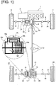
- Figure 1 illustrates the configuration of the drive system of a front wheel drive based four-wheel drive vehicle to which is applied the clutch control device.
- the drive system configuration of the four-wheel drive vehicle will be described below based on Figure 1 .
- the front wheel drive system of the four-wheel drive vehicle is provided with a transverse engine 1 (drive source), a transmission 2, a front differential 3, a left front wheel drive shaft 4, a right front wheel drive shaft 5, a left front wheel 6 (main drive wheel), and a right front wheel 7 (main drive wheel), as illustrated in Figure 1 . That is, the drive force is transmitted from the transverse engine 1 and the transmission 2 to the left and right front wheel drive shafts 4, 5 via the front differential 3, and constantly drives the left and right front wheels 6, 7 while allowing a differential rotation.
- the rear wheel drive system of the four-wheel drive vehicle comprises a dog clutch 8 (dog clutch), a bevel gear 9, an output pinion 10, a rear wheel output shaft 11, and a propeller shaft 12, as illustrated in Figure 1 . Further provided are a drive pinion 13, a ring gear 14, a rear differential 15, an electronically controlled coupling 16 (friction clutch), a left rear wheel drive shaft 17, a right rear wheel drive shaft 18, a left rear wheel 19 (auxiliary drive wheel), and a right rear wheel 20 (auxiliary drive wheel).
- 21 is a universal joint.
- the rotation of the drive system (rotation of the propeller shaft 12, etc.) on the downstream side of the dog clutch 8 is stopped by releasing this dog clutch 8 and electronically controlled coupling 16; it is thereby possible to suppress friction loss and oil stirring loss to achieve improved fuel efficiency.
- the dog clutch 8 is a dog clutch that is provided at a drive branch position from the left and right front wheels 6, 7 to the left and right rear wheels 19, 20, and that separates the system for transmitting drive force to the left and right rear wheels 19, 20 from the system for transmitting drive force to the left and right front wheels 6, 7 by releasing the clutch.
- the input side meshing member of the dog clutch 8 is connected to the differential case of the front differential 3, and the output side meshing member of the dog clutch 8 is connected to the bevel gear 9.
- the dog clutch 8, the bevel gear 9, the output pinion 10, and a portion of the rear wheel output shaft 11 are incorporated in a transfer case 23 that is fixed to a position adjacent to the front differential housing 22.
- a dog clutch in which one of a pair of meshing members is a fixing member and the other is a movable member, in which a spring that biases in the engaging direction is provided between the fixing member and the movable member, and in which a screw groove that can be fitted with a solenoid pin is formed on the outer perimeter of the movable member, is used as this dog clutch 8.
- this dog clutch 8 releases the engagement due to the movable member making a stroke in the releasing direction while being rotated and the stroke amount exceeding a predetermined amount.
- the electronically controlled coupling 16 is a friction clutch that is provided in a downstream position of the dog clutch 8, and that allocates a portion of the drive force from the transverse engine 1 to the left and right rear wheels 19, 20, in accordance with the clutch engagement capacity.
- An input side clutch plate of the electronically controlled coupling 16 is connected to a left side gear of the rear differential 15, and an output side clutch plate is connected to a left rear wheel drive shaft 17.
- This electronically controlled coupling 16 is incorporated in a coupling case 25 that is fixed in a position adjacent to the rear differential housing 24.
- an electronically controlled coupling comprising a multi-plate friction clutch in which multiple input-side and output-side plates are alternately arranged, a fixed cam piston and a movable cam piston which have opposing cam surfaces, and a cam member that is interposed between the opposing cam surfaces, is used as this electronically controlled coupling 16.
- the engagement of the electronically controlled coupling 16 is carried out by the movable cam piston being stroked in the clutch engaging direction in accordance with the rotation angle to increase the frictional engagement force of the multi-plate friction clutch, due to a cam action that expands the piston gap that is generated by an electric motor rotating the movable cam piston.
- the release of the electronically controlled coupling 16 is carried out by the movable cam piston being moved in the clutch releasing direction in accordance with the rotation angle to decrease the frictional engagement force of the multi-plate friction clutch, due to a cam action that reduces the piston gap that is generated by the electric motor rotating the movable cam piston in the opposite direction of the engaging direction.
- the electronically controlled coupling 16 comprises a multi-plate friction clutch 16a, a clutch chamber 16b, a partition wall 16c, an oil chamber 16d, an oil passage 16e, and an open/close valve 16f, as illustrated in the enlarged view of the coupling in Figure 1 .
- the clutch chamber 16b houses the multi-plate friction clutch 16a.
- the oil chamber 16d is a separate chamber partitioned from the clutch chamber 16b by the partition wall 16c.
- the oil passage 16e places the clutch chamber 16b and the oil chamber 16d in communication, and conveys oil from the clutch chamber 16b to the oil chamber 16d by centrifugal force.
- the open/close valve 16f is provided on the partition wall 16c, and is configured to open/close the valve in conjunction with the stroke movement of the movable cam piston, so that the valve closes at the full release position and opens at a position other than the full release position of the movable cam piston. That is, when the electronically controlled coupling 16 is disengaged and the open/close valve 16f is closed, the oil in the clutch chamber 16b flows into the oil chamber 16d by centrifugal force and fills the oil chamber 16d with oil. When the open/close valve 16f is opened, the oil in the oil chamber 16d flows into the clutch chamber 16b. In this manner, when the electronically controlled coupling 16 is disengaged (for example, when the "standby two-wheel drive mode" is selected), the oil stirring resistance is suppressed.
- Figure 2 illustrates the configuration of the control system of the front wheel drive based four-wheel drive vehicle to which is applied the clutch control device.
- the control system configuration of the four-wheel drive vehicle will be described below based on Figure 2 .
- the control system of the four-wheel drive vehicle is provided with an engine control module 31, a transmission control module 32, an ABS actuator control unit 33, and a 4WD control unit 34, as illustrated in Figure 2 .
- the engine control module 31 is a control device of the transverse engine 1, which inputs detection signals from an engine rotational frequency sensor 35, an accelerator position opening amount sensor 36, and the like.
- Engine rotational frequency information and accelerator position opening amount information are input from this engine control module 31 to the 4WD control unit 34 via a CAN communication line 37.
- the transmission control module 32 is a control device of the transmission 2, which inputs detection signals from a transmission input rotational frequency sensor 38, the transmission output rotational frequency sensor 39, and the like. Gear ratio information (gear ratio information) is input from this transmission control module 32 to the 4WD control unit 34 via the CAN communication line 37.
- the ABS actuator control unit 33 is a control device of an ABS actuator which controls the brake fluid pressure of each wheel, which inputs detection signals from a yaw rate sensor 40, a lateral G sensor 41, a longitudinal G sensor 42, and wheel speed sensors 43, 44, 45, 46, and the like.
- Yaw rate information, lateral G information, longitudinal G information, and wheel speed information of each wheel are input from this ABS actuator control unit 33 to the 4WD control unit 34 via the CAN communication line 37.
- steering angle information from a steering angle sensor 47 is input to the 4WD control unit 34 via the CAN communication line 37.
- the average value of the left and right rear wheel speed information will be the vehicle speed information (VSP information).
- the 4WD control unit 34 is a control device that controls the engagement and disengagement of the dog clutch 8 and the electronically controlled coupling 16, and carries out a calculation step based on various input information.
- the control unit outputs drive control commands to a dog clutch actuator 48 (solenoid) and an electronically controlled coupling actuator 49 (electric motor).
- a drive mode selection switch 50, a brake switch 51 that detects the presence/absence of a braking operation, a ring gear rotational frequency sensor 52, a dog clutch stroke sensor 53, a motor rotation angle sensor 54, and the like are provided as input information sources from other than the CAN communication line 37.
- the drive mode selection switch 50 is a switch with which a driver switches to select among a "2WD mode,” a "lock mode,” and an “auto mode.”
- a driver switches to select among a "2WD mode,” a "lock mode,” and an "auto mode.”
- a front wheel drive 2WD state in which the dog clutch 8 and the electronically controlled coupling 16 are released is maintained.
- a full 4WD state in which the dog clutch 8 and the electronically controlled coupling 16 are engaged is maintained.
- the “auto mode” the engagement and disengagement of the dog clutch 8 and the electronically controlled coupling 16 are automatically controlled in accordance with the vehicle state (vehicle speed VSP, accelerator position opening amount ACC).
- auto mode there is a choice between an “eco-auto mode” and a “sports auto mode,” where the release state of the electronically controlled coupling 16 in “standby two-wheel drive mode,” in which the dog clutch 8 is engaged, will differ and depends upon the selected mode. That is, when “eco-auto mode” is selected, the electronically controlled coupling 16 is placed in a fully released state and waits, and when “sports auto mode” is selected, the electronically controlled coupling 16 is placed in a released state immediately before engagement and waits.
- the ring gear rotational frequency sensor 52 is a sensor for acquiring output rotational speed information of the dog clutch 8, and which calculates the output side rotational frequency of the dog clutch 8 by taking into consideration the rear side gear ratio and the front side gear ratio upon calculation with respect to the detected value of the ring gear rotational frequency.
- the input rotational speed information of the dog clutch 8 is obtained by calculating the average value of the left front wheel speed from the left front wheel speed sensor 43 and the right front wheel speed from the right front wheel speed sensor 44.
- Figure 3 illustrates a drive mode switching map corresponding to the vehicle speed VSP and the accelerator position opening amount ACC used in the clutch control when the "auto mode" is selected
- Figure 4 illustrates the switching transition of the drive mode (disconnected, two-wheel drive mode/standby two-wheel drive mode/connected, four-wheel drive mode).
- the drive mode switching configuration will be described below, based on Figure 3 and Figure 4 .
- the drive mode switching map is set to be separated into the disconnected, two-wheel drive mode (Disconnect), the standby two-wheel drive mode (Standby), and the connected, four-wheel drive mode (Connect), in accordance with the vehicle speed VSP and the accelerator position opening amount ACC, as illustrated in Figure 3 .
- These three drive modes are separated by a region dividing line A in which the accelerator position opening amount ACC is increased proportionally with the increase in the vehicle speed VSP from a base point a of a set vehicle speed VSP0 at which the accelerator position opening amount is zero, and a region dividing line B of a constant accelerator position opening amount ACC0, which is drawn from an intersection b with the region dividing line A toward the high vehicle speed side.
- the disconnected, two-wheel drive mode (Disconnect) is set in the region in which the accelerator position opening amount ACC is less than or equal to the set accelerator position opening amount ACC0, and which is surrounded by the vehicle speed axis line on which the accelerator position opening amount ACC is zero, the region dividing line A, and the region dividing line B. That is, the mode is set in a region in which the frequency of occurrence of the differential rotation of the left and right front wheels 6, 7 and the left and right rear wheels 19, 20 due to wheel slip is extremely low, since the accelerator position opening amount ACC is less than or equal to the set accelerator position opening amount ACC0; and even if wheel slip does occur, the four-wheel drive requirement is low, so that slip increases slowly.
- the standby two-wheel drive mode (Standby) is set in a high vehicle speed region in which the accelerator position opening amount ACC exceeds the set accelerator position opening amount ACC0, and which is defined by the region dividing line A and the region dividing line B. That is, the mode is set in a region in which, since the accelerator position opening amount ACC exceeds the set accelerator position opening amount ACC0, while the 4WD requirement is low because the vehicle speed VSP is in a high vehicle speed region, if differential rotation of the left and right front wheels 6, 7 and the left and right rear wheels 19, 20 is generated due to wheel slip, there is a high probability that the slip will increase rapidly.
- the connected, four-wheel drive mode (Connect) is set in the region surrounded by the accelerator position opening amount axis line on which the vehicle speed VSP is zero, the vehicle speed axis line on which the accelerator position opening amount ACC is zero, and the region dividing line A. That is, the mode is set in a region in which the 4WD requirement is high, such as when starting or upon high-load travel in which the vehicle speed VSP is low but the accelerator position opening amount ACC is high.
- the travel mode becomes 2WD travel (Disconnect) in which both the dog clutch 8 and the electronically controlled coupling 16 are released, as illustrated in frame C of Figure 4 .
- front wheel drive 2WD travel (Disconnect)
- the electronically controlled coupling 16 is frictionally engaged.
- differential rotation control of the front and rear wheels to suppress wheel slip is carried out by engaging the dog clutch 8 and allocating drive force to the left and right drive wheels 19, 20.
- the travel mode becomes 2WD travel (Standby) in which the dog clutch 8 is engaged and the electronically controlled coupling 16 is released, as illustrated in frame D of Figure 4 .
- front wheel drive 2WD travel (Standby) in which drive force is transmitted only to the left and right front wheels 6, 7, is maintained.
- Differential rotation control of the front and rear wheels to suppress wheel slip is carried out by allocating drive force to the left and right rear wheels 19, 20 with good responsiveness by this frictional engagement of the electronically controlled coupling 16.
- the travel mode becomes 4WD travel (Connect) in which both the dog clutch 8 and the electronically controlled coupling 16 are engaged, as illustrated in frame E of Figure 4 .
- a drive force distribution control is carried out, which achieves the optimum drive force distribution to the left and right front wheels 6, 7, and to the left and right rear wheels 19, 20 that is suited to the road conditions (for example, control at the time of start, control corresponding to the accelerator position opening amount, and control corresponding to the vehicle speed).
- the switching transition between the 2WD travel (Disconnect), 2WD travel (Standby), and 4WD travel (Connect) is carried out by a switching request of the drive mode that is output when an operating point, which is determined by the vehicle speed VSP and the accelerator position opening amount ACC, crosses the region dividing line A and the region dividing line B illustrated in Figure 3 .
- the switching transition speed of each drive mode is determined so that the transition speed to a drive mode that meets a 4WD request is prioritized over the transition speed to the disconnected, two-wheel drive mode that meets a fuel efficiency request.
- the switching transition speed of 2WD travel (Disconnect) ⁇ 2WD travel (Standby) is configured to be fast
- the switching transition speed of 2WD travel (Standby) ⁇ 2WD travel (Disconnect) (arrow G in Figure 4 ) is configured to be slow
- the switching transition speed of 2WD travel (Disconnect) ⁇ 4WD travel (Connect) (arrow H in Figure 4 ) is configured to be fast
- the switching transition speed of 4WD travel (Connect) ⁇ 2WD travel (Disconnect) (arrow I in Figure 4 ) is configured to be slow.
- the switching transition speed of 2WD travel (Standby) ⁇ 4WD travel (Connect) (arrow J in Figure 4 ) is configured to be the same fast speed as the switching transition speed of 4WD travel (Connect) ⁇ 2WD travel (Standby) (arrow K in Figure 4 ).
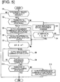
- FIG. 5 illustrates the flow of the clutch control process that is executed in the 4WD control unit 34 (clutch control means). Each of the steps in Figure 5 will be described below, which represents the clutch control process configuration.
- This flowchart is started when the "auto mode” is selected as well as the “disconnected, two-wheel drive mode,” in which both the dog clutch 8 and the electronically controlled coupling 16 are disengaged, is selected as the drive mode.
- Step S1 whether or not there is a request to engage the dog clutch 8 is determined. If YES (engagement request present), the process proceeds to Step S2, and if NO (engagement request absent), the process proceeds to END.
- a request to engage the dog clutch 8 is output when the "disconnected, two-wheel drive mode" is selected and it is determined that there is a mode transition to the "connected, four-wheel drive mode” or the "standby two-wheel drive mode.”
- Step S2 following the determination that there is an engagement request in Step S1, it is determined whether or not it is a transition to the connected, four-wheel drive mode. If YES (transition to the connected, four-wheel drive mode), the process proceeds to Step S4, and if NO (transition to standby two-wheel drive mode), the process proceeds to Step S3.
- Step S3 following the determination that it is a transition to the "standby two-wheel drive mode" in Step S2, an immediately before engagement command is output to the coupling actuator 49 of the electronically controlled coupling 16, and the process proceeds to Step S4.
- the immediately before engagement command of the electronically controlled coupling 16 is a command to maintain the released state immediately before engagement of the electronically controlled coupling 16, and a command to open the closed open/close valve 16f.
- Step S4 following the output of the immediately before engagement command of the electronically controlled coupling 16 in Step S3, it is determined whether or not the value T of the timer, which is initiated starting from the time that a request to engage the dog clutch 8 is output, is greater than or equal to a set value T0. In the case of YES (T ⁇ T0), the process proceeds to Step S4, and in the case of NO (T ⁇ T0), the determination of Step S3 is repeated.
- the set value T0 is set to the time that is required for most of the lubrication oil, which is transferred to the oil chamber 16d, to flow into the clutch chamber 16b via the open open/close valve 16 when the open/close valve 16 is opened by putting the electronically controlled coupling 16, which is in a disengaged state, in an immediately before engagement state.
- step S5 following the determination that it is a transition to the "connected, four-wheel drive mode" in step S2, or, the determination that T ⁇ 0 in step 4, or, the determination that ⁇ N> ⁇ in step S7, an engagement command is output to the coupling actuator 49 of the electronically controlled coupling 16, and the process proceeds to Step S6.
- the engagement command to the coupling actuator 49 will be a high-gradient command with which the electronically controlled coupling 16 is put in a fully engaged state in a short period of time if transitioning to the "connected, four-wheel drive mode," and a low-gradient command with which the electronically controlled coupling 16 is gradually transitioned from a disengaged state to a fully engaged state if transitioning to the "standby two-wheel drive mode.”
- Step S6 following the output of the engagement command of the electronically controlled coupling 16 in Step S5, the clutch differential rotation speed ⁇ N, which is the differential rotation of the dog clutch 8, is calculated, and the process proceeds to Step S7.
- the clutch differential rotation speed ⁇ N is calculated by subtracting the output rotational speed (calculated value based on the detection value of the ring gear rotational frequency) from the input rotational speed (average value of the left and right front wheel speeds) of the dog clutch 8.
- Step S7 following the calculation of the clutch differential rotation speed ⁇ N in Step S6, it is determined whether or not the clutch differential rotation speed ⁇ N is less than or equal to the rotation synchronization determination threshold value ⁇ . If YES ( ⁇ N ⁇ ), the process proceeds to Step S8, and if NO ( ⁇ N> ⁇ ), the process returns to Step S6.
- the rotation synchronization determination threshold value ⁇ is a clutch differential rotation speed value for determining a rotationally synchronized state in which the engagement of the dog clutch 8 is possible, and a fixed value may be given, or a variable value corresponding to the vehicle speed VSP, or the like, may be given.
- Step S8 following the determination that ⁇ N ⁇ in Step S7, or, the determination that clutch engagement is incomplete in Step S9, an engagement command is output to the clutch actuator 48 of the dog clutch 8, and the process proceeds to Step S9.
- Step S9 following the output of an engagement command to the dog clutch 8 in Step S8, it is determined whether or not the engagement of the dog clutch 8 is complete. If YES (clutch engagement complete), the process proceeds to Step S10, and if NO (clutch engagement incomplete), the process returns to Step S8.
- the determination of whether or not the engagement of the dog clutch 8 is complete is carried out on the basis of stroke information from the dog clutch stroke sensor 53.
- Step S10 following the determination that clutch engagement is complete in Step S9, it is determined whether or not it is a transition to the connected, four-wheel drive mode. If YES (transition to the connected, four-wheel drive mode), the process proceeds to END, and if NO (transition to standby two-wheel drive mode), the process proceeds to Step S11.
- Step S11 following the determination that it is a transition to the standby two-wheel drive mode in Step S10, a disengagement command is output to the coupling actuator 49 of the electronically controlled coupling 16, and the step proceed to END.
- the command will be a command to fully disengage the electronically controlled coupling 16
- the command will be a command to maintain the released state immediately before engagement of the electronically controlled coupling 16.
- an engagement request is output to the dog clutch 8 at a timing when the operating point crosses the region dividing line B.
- Step S1 when transitioning from the "disconnected, two-wheel drive mode" to the "connected, four-wheel drive mode" and an engagement request is output to the dog clutch 8, the process proceeds to Step S1 ⁇ Step S2 ⁇ Step S5 ⁇ Step S6 ⁇ Step S7 in the flowchart of Figure 5 .
- Step S5 if there is a request to engage the dog clutch 8, an engagement command is immediately output to the coupling actuator 49 of the electronically controlled coupling 16.
- Step S6 the clutch differential rotation speed ⁇ N, which is the differential rotation of the dog clutch 8, is calculated, and in Step S7, it is determined whether or not the clutch differential rotation speed ⁇ N is less than or equal to the rotation synchronization determination threshold value ⁇ . Then, while it is determined that ⁇ N> ⁇ in Step S7, the flow that proceeds to Step S5 ⁇ S6 ⁇ S7 is repeated.
- Step S7 when the rotation synchronization determination condition is satisfied in Step S7, the process proceeds from Step S7 to S8 ⁇ Step S9 in the flowchart of Figure 5 , and in Step S8, an engagement command is output to the clutch actuator 48 of the dog clutch 8.
- Step S9 it is determined whether or not the engagement of the dog clutch 8 is complete, and while it is determined that the clutch engagement is incomplete, the flow that proceeds to Step S8 ⁇ Step S9 is repeated.
- Step S9 When it is determined that the engagement of the dog clutch 8 is complete in Step S9, the process proceeds from Step S9 to Step S10 ⁇ END.
- the disengaged dog clutch 8 starts to engage.
- the open/close valve 16 opens at time t1 when the electronically controlled coupling 16, which is in a disengaged state, starts to engage, and the lubrication oil, which is transferred to the oil chamber 16d, starts to flow into the clutch chamber 16b.
- time t2 only some of the lubrication oil has flowed in, and the engagement of the dog clutch 8 is started in this state. In other words, all of the lubrication oil, which is transferred to the oil chamber 16d, does not flow into the clutch chamber 16b until time t3.
- Step S1 when transitioning from the "disconnected, two-wheel drive mode" to the "standby two-wheel drive mode" and an engagement request is output to the dog clutch 8, the process proceeds to Step S1 ⁇ Step S2 ⁇ Step S3 ⁇ Step S4 in the flowchart of Figure 5 .
- Step S3 an immediately before engagement command is output to the coupling actuator 49 of the electronically controlled coupling 16, and in Step S4, it is determined whether or not the value T of the timer, which is initiated starting from the time that a request to engage the dog clutch 8 is output, is greater than or equal to a set value T0. While T ⁇ T0, the flow that proceeds to Step S3 ⁇ Step S4 is repeated, and the start of engagement of the electronically controlled coupling 16 is postponed.
- Step S5 When T ⁇ T0, the process proceeds from Step S4 to Step S5 ⁇ Step S6 ⁇ Step S7.
- Step S5 an engagement command is output to the coupling actuator 49 of the electronically controlled coupling 16.
- Step S6 the clutch differential rotation speed ⁇ N, which is the differential rotation of the dog clutch 8, is calculated, and in Step S7, it is determined whether or not the clutch differential rotation speed ⁇ N is less than or equal to the rotation synchronization determination threshold value ⁇ . Then, while it is determined that ⁇ N> ⁇ in Step S7, the flow that proceeds to Step S5 ⁇ S6 ⁇ S7 is repeated.
- Step S7 when the rotation synchronization determination condition is satisfied in Step S7, the process proceeds from Step S7 to S8 ⁇ Step S9 in the flowchart of Figure 5 , and in Step S8, an engagement command is output to the clutch actuator 48 of the dog clutch 8.
- Step S9 it is determined whether or not the engagement of the dog clutch 8 is complete, and while it is determined that the clutch engagement is incomplete, the flow that proceeds to Step S8 ⁇ Step S9 is repeated.
- Step S9 a disengagement command is output to the coupling actuator 49 of the electronically controlled coupling 16. If the "eco-auto mode” is selected, the command will be a command to fully disengage the electronically controlled coupling 16, and if the "sports auto mode” is selected, the command will be a command to maintain the released state immediately before engagement of the electronically controlled coupling 16.
- the dog clutch 8 is a dog clutch that is engaged by putting the input and output rotations of the clutch into a synchronized state. Accordingly, when the "disconnected, two-wheel drive mode," in which the dog clutch 8 is released, is selected, and there is a request to engage the dog clutch 8, it is necessary to put the input and output rotations of the dog clutch 8 in a rotationally synchronized state by engaging the electronically controlled coupling 16.
- the drive modes will be the "standby two-wheel drive mode” in which only the dog clutch 8 is engaged, in addition to the "disconnected, two-wheel drive mode” and the “connected, four-wheel drive mode.”
- a request to engage the dog clutch 8 is output when switching from the "disconnected, two-wheel drive mode” to the "connected, four-wheel drive mode,” and when switching from the "disconnected, two-wheel drive mode” to the "standby two-wheel drive mode.” If the timing from the request to engage the dog clutch 8 to the start of engagement of the electronically controlled coupling 16 is always set to the same timing in either switching of the drive modes, there are the following problems.
- the synchronization timings are varied in accordance with the destination drive mode.
- the configuration is such that the engagement start timing of the electronically controlled coupling 16 when a transition is made to the "connected, four-wheel drive mode” is set to an earlier timing compared to when there is a transition to the "standby two-wheel drive mode.”
- the "disconnected, two-wheel drive mode” is a high energy conservation performance two-wheel drive mode that suppresses friction loss and the like by stopping the rotation of the system for transmitting drive force to the left and right rear wheels 19, 20 from the dog clutch 8 to the electronically controlled coupling 16.
- the "connected, four-wheel drive mode” is a high drive performance four-wheel drive mode that allocates the drive force from the transverse engine 1 to the four wheels at the time of an acceleration request and the like.
- the "standby two-wheel drive mode” is a two-wheel drive mode having an improved responsiveness when a transition is made to a four-wheel drive state compared to the "disconnected, two-wheel drive mode,” by engaging the dog clutch 8 in advance. Additionally, when there is a request to engage the dog clutch 8, it is necessary to increase the output rotation of the dog clutch 8 and place the input and output rotations in a synchronized state by engaging the electronically controlled coupling 16.
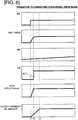
- the inventors paid particular attention to the fact that, in contrast, when switching from the "disconnected, two-wheel drive mode" to the "connected, four-wheel drive mode,” that is, when switching from a two-wheel drive state to a four-wheel drive state, more responsiveness is required than a switching transition in which a two-wheel drive state is maintained. Accordingly, when switching from the "disconnected, two-wheel drive mode" to the “connected, four-wheel drive mode,” the engagement of the electronically controlled coupling 16 is started at the early timing (time t1 in Figure 6 ) when a request to engage the dog clutch 8 is output. Thus, the state becomes a rotationally synchronized state after a short time (time t1 - t2 in Figure 6 ) from the engagement request, and responsiveness of switching to the "connected, four-wheel drive mode" is secured.
- the engagement of the electronically controlled coupling 16 is started at a later timing (time t3 of Figure 7 ) when the clutch chamber 16b is filled with the lubrication oil, when switching from the "disconnected, two-wheel drive mode" to the "standby two-wheel drive mode.” Accordingly, the state does not become a rotationally synchronized state until after a long time (time t1 - t3 of Figure 7 ), the travel region in the "disconnected, two-wheel drive mode" is substantially expanded, and energy conservation performance (fuel efficiency) is secured. As a result, a balance between securing four-wheel drive performance and securing energy conservation performance can be achieved, when there is a request to engage the dog clutch 8.
- the configuration is such that the "disconnected, two-wheel drive mode” is set in a low accelerator position opening amount and high vehicle speed region, the “standby two-wheel drive mode” is set in a high accelerator position opening amount and high vehicle speed region, and the “connected, four-wheel drive mode” is set in all accelerator position opening amount and low vehicle speed regions.
- the switching from the "disconnected, two-wheel drive mode" to the “connected, four-wheel drive mode” is carried out in a low vehicle speed and low accelerator position opening amount region (refer to Figure 3 ).
- this low vehicle speed and low accelerator position opening amount region the load on the electronically controlled coupling 16 is small, and the rotation synchronization can be started without waiting for the lubrication oil to completely flow into the clutch chamber 16b side.
- the switching from the "disconnected, two-wheel drive mode” to the "standby two-wheel drive mode” is carried out in a high vehicle speed and high accelerator position opening amount region (refer to Figure 3 ). In this high vehicle speed and high accelerator position opening amount region, the load on the electronically controlled coupling 16 is large.
- An electronically controlled coupling 16 of the first embodiment comprises a clutch chamber 16b, an oil chamber 16d partitioned from the clutch chamber 16b by a partition wall 16c, an oil passage 16e that brings the clutch chamber 16b and the oil chamber 16d into communication, and an open/close valve 16f provided on the partition wall 16c.
- the configuration thereof is such that when there is a request to engage the dog clutch 8 at the time of switching to the "connected, four-wheel drive mode," the engagement of the electronically controlled coupling 16 starts immediately without waiting for the oil in the oil chamber 16d to flow into the clutch chamber 16b via the open/close valve 16f. That is, if the engagement of the electronically controlled coupling 16 is started in a state in which the clutch chamber 16b is filled with oil, the stirring resistance due to oil is high. In contrast, if the engagement of the electronically controlled coupling 16 is started in a state in which the clutch chamber 16b is not filled with oil, the stirring resistance due to oil is low.
- the configuration is such that when there is a request to engage the dog clutch 8 at the time of switching to the "standby two-wheel drive mode," the engagement of the electronically controlled coupling 16 starts after waiting for the oil in the oil chamber 16d to flow into the clutch chamber 16b via the open/close valve 16f.
- the dog clutch 8 is disposed in an upstream position of the output pinion 10 and the bevel gear 9 provided at a drive branch position to the left and right front wheels 6, 7.
- the electronically controlled coupling 16 is configured to be disposed in the position of the left rear wheel drive shaft 17, which extends to the left rear wheel 19, downstream of the bevel gear 9 and the output pinion 10 via the rear wheel output shaft 11, the propeller shaft 12 and the drive pinion 13, the ring gear 14, and the rear differential 15.
- the second embodiment is an example in which the clutch control device is applied to a rear wheel drive based four-wheel drive vehicle, and the positional relationship of the dog clutch and the friction clutch that sandwich the differential is reversed from the positional relationship thereof in the first embodiment.
- Figure 8 illustrates the configuration of the drive system of a rear wheel drive based four-wheel drive vehicle to which is applied the clutch control device.
- the drive system configuration of the four-wheel drive vehicle will be described below based on Figure 8 .
- the rear wheel drive system of the four-wheel drive vehicle is provided with a transverse engine 61 (drive source), a transmission 62, a rear propeller shaft 63, a rear differential 64, a left rear wheel drive shaft 65, a right rear wheel drive shaft 66, a left rear wheel 67 (main drive wheel), and a right rear wheel 68 (main drive wheel), as illustrated in Figure 8 . That is, the drive force that has passed through the transverse engine 61 and the transmission 62 is transmitted to the left and right rear wheel drive shafts 65, 66 via the rear propeller shaft 63 and the rear differential 64, and constantly drives the left and right rear wheels 67, 68 while allowing a differential rotation.
- a transfer mechanism is configured to comprise, inside a transfer case 69, an electronically controlled coupling 70 (friction clutch), an input side sprocket 71, an output side sprocket 72, and a chain 73, as illustrated in Figure 8 .
- a front propeller shaft 74 that is connected to the output side sprocket 72, a front differential 75, a left front wheel drive shaft 76, a right front wheel drive shaft 77, a left front wheel 78 (auxiliary drive wheel), and a right front wheel 79 (auxiliary drive wheel) are provided.
- the electronically controlled coupling 70 is disposed inside the transfer case 69 in an upstream position of the input side sprocket 71 (main drive system side position).
- the rotation of the drive system (rotation of the front propeller shaft 74, etc.) on the downstream side of the electronically controlled coupling 70 is stopped by releasing these electronically controlled coupling 70 and dog clutch 80; it is thereby possible to suppress friction loss and oil stirring loss so that improved fuel efficiency can be realized.
- the first embodiment is configured so that the dog clutch 8 is disposed in the drive branch-side transmission system path and the electronically controlled coupling 16 is disposed in the auxiliary drive wheel-side transmission system path, which sandwich the rear differential 15, of the system for transmitting drive force to the left and right rear wheels 19, 20, which are the auxiliary drive wheels.
- the clutch differential rotation speed ⁇ N which has been decreasing with time, will reach a limit at a certain differential rotation; thereafter, the clutch differential rotation speed ⁇ N shifts to an increase, and the clutch differential rotation speed ⁇ N increases with time.
- the second embodiment is configured so that the electronically controlled coupling 70 is disposed in the drive branch-side transmission system path and the dog clutch 80 is disposed in the auxiliary drive wheel-side transmission system path, which sandwich the front differential 75, of the system for transmitting drive force to the left and right front wheels 78, 79, which are the auxiliary drive wheels.
- the clutch control device for a four-wheel drive vehicle of the present invention was described above based on the first embodiment and the second embodiment, but specific configurations thereof are not limited to these embodiments, and various modifications and additions to the design can be made without departing from the scope of the invention according to each claim in the Claims section.
- a dog clutch 8 is disposed in an upstream position of the transfer mechanism as a dog clutch.
- a dog clutch may be disposed in a downstream position of the transfer mechanism, in the propeller shaft position, as the dog clutch.
- an electronically controlled coupling 16 is disposed in an intermediate position of the left rear wheel drive shaft 17 as the friction clutch.
- an electronically controlled coupling may be disposed in an intermediate position of the right rear wheel drive shaft as the friction clutch.
- the clutch control device of the present invention is applied to a front wheel drive based four-wheel drive vehicle (4WD engine vehicle) in which an engine is mounted as the drive source.
- the clutch control device of the present invention is applied to a rear wheel drive based four-wheel drive vehicle (4WD engine vehicle) in which the left and right rear wheels are the main drive wheels.
- the clutch control device may be applied to a rear wheel drive based four-wheel drive vehicle in which the positional relationship of the dog clutch and the friction clutch is set with the same relationship as in the first embodiment.
- the clutch control device may be applied to a front wheel drive based four-wheel drive vehicle in which the positional relationship of the dog clutch and the friction clutch is set with the same relationship as in the second embodiment.
- the clutch control device can of course be applied to other vehicles besides a 4WD engine vehicle, such as a 4WD hybrid vehicle in which an engine and an electric motor are mounted as drive sources, or a 4WD electric vehicle in which an electric motor is mounted as the drive source.
Landscapes
- Engineering & Computer Science (AREA)
- Mechanical Engineering (AREA)
- General Engineering & Computer Science (AREA)
- Chemical & Material Sciences (AREA)
- Combustion & Propulsion (AREA)
- Transportation (AREA)
- Arrangement And Mounting Of Devices That Control Transmission Of Motive Force (AREA)
- Arrangement And Driving Of Transmission Devices (AREA)
- Mechanical Operated Clutches (AREA)
Claims (6)
- Fahrzeug mit Allradantrieb mit einer Kupplungssteuerungsvorrichtung, wobei- ein Paar von den linken und rechten Vorderrädern (6, 7 oder 78, 79) und den linken und rechten Hinterräder (19, 20 oder 67, 68) des Fahrzeugs mit Allradantrieb als Hauptantriebsräder (6, 7 oder 67, 68), die mit einer Antriebsquelle (1, 61) verbunden sind, und das andere Paar als Hilfsantriebsräder (19, 20 oder 78, 79), die mit der Antriebsquelle (1, 61) verbunden sind, über eine Kupplung (8, 16) festgelegt ist, wobei die Kupplungssteuerungsvorrichtung aufweist- mehrere Kupplungen (8, 16), das heißt, eine Klauenkupplung (8) und eine Reibungskupplung (16), die jeweils getrennt in einem antriebsstrangseitigen Übertragungssystempfad und in einem hilfsantriebsradseitigen Übertragungssystempfad, die ein Differential umschließen, eines Systems zum Übertragen einer Antriebskraft für die Hilfsantriebsräder angeordnet sind, wobei- die Klauenkupplung (8) das System zum Übertragen einer Antriebskraft auf die Hilfsantriebsräder vom System zum Übertragen einer Antriebskraft zu den Hauptantriebsrädern durch Lösen der Kupplung (8) trennt, und die Reibungskupplung (16) einen Bereich der Antriebskraft von der Antriebsquelle (1) den Hilfsantriebsrädern in Übereinstimmung mit einer Kupplungseingriffskapazität zuordnet, wobei- das Fahrzeug mit Allradantrieb einen getrennten Zweiradantriebsmodus, in dem die Klauenkupplung (8) und die Reibungskupplung (16) ausgekuppelt sind, einen Standby-Zweiradantriebsmodus, in dem die Klauenkupplung (8) eingekuppelt und die Reibungskupplung (16) ausgekoppelt ist und einen verbundenen Vierradantriebsmodus umfasst, in dem die Klauenkupplung (8) und die Reibungskupplung (16) eingekuppelt sind,gekennzeichnet durch- eine Kupplungssteuerungseinrichtung (34), die eine Steuerung zum Starten eines Eingriffs der Klauenkupplung (8) ausführt, die in einem ausgekuppelten Zustand ist, nachdem die Klauenkupplung (8) in einen drehsynchronisierten Zustand durch Eingriff der Reibungskupplung (16) gebracht ist, wenn eine Aufforderung besteht, die Klauenkupplung (8) einzukuppeln; und- die Kupplungssteuerungseinrichtung einen Eingriffs-Startzeitpunkt der Reibungskupplung (16) festlegt, wenn ein Übergang zum verbundenen Vierradantriebsmodus zu einem früheren Zeitpunkt im Vergleich ausgeführt wird, wenn ein Übergang zum Standby-Zweiradantriebsmodus ausgeführt wird, wenn eine Aufforderung besteht, die Klauenkupplung (8) während eines Zustands, in dem der getrennte Zweiradantriebsmodus ausgewählt ist, einzukuppeln.
- Fahrzeug mit Allradantrieb mit der Kupplungssteuerungsvorrichtung gemäß Anspruch 1, wobei- die Kupplungssteuerungseinrichtung den getrennten Zweiradantriebsmodus auf ein geringes Gaspedal-Positionsöffnungsausmaß und einen hohen Fahrzeugdrehzahlbereich festlegt, den Standby-Zweiradantriebsmodus auf ein hohes Gaspedal-Positionsöffnungsausmaß und einen hohen Fahrzeugdrehzahlbereich festlegt und den verbundenen Vierradantriebsmodus auf ein Gaspedal-Positionsöffnungs-Gesamtausmaß und einen niedrigen Fahrzeugdrehzahlbereich festlegt.
- Fahrzeug mit Allradantrieb mit der Kupplungssteuerungsvorrichtung gemäß Anspruch 1 oder 2, wobei- die Reibungskupplung (16) eine Kupplungskammer (16b), die eine Mehrplatten-Reibungskupplung (16a) aufnimmt, eine Ölkammer (16d), die von der Kupplungskammer (16b) durch eine Trennwand (16c) getrennt ist, einen Ölflusskanal, der die Kupplungskammer (16b) und die Ölkammer (16d) kommunikativ anordnet und Schmieröl von der Kupplungskammer (16b) zur Ölkammer (16d) durch eine Zentrifugalkraft leitet und ein Auf-Zu-Ventil (16f), das auf der Trennwand (16c) vorgesehen ist, aufweist, und wobei- die Kupplungssteuerungseinrichtung, wenn eine Aufforderung besteht, die Klauenkupplung (8) zu einem Schaltzeitpunkt vom getrennten Zweiradantriebsmodus zum verbundenen Vierradantriebsmodus einzukuppeln, einen Eingriff der Reibungskupplung (16) unmittelbar zu starten, ohne auf das Öl in der Ölkammer (16d) zu warten, um in die Kupplungskammer (16b) über das Auf-Zu-Ventil (16f) zu fließen.
- Fahrzeug mit Allradantrieb mit der Kupplungssteuerungsvorrichtung gemäß Anspruch 3, wobei- die Kupplungssteuerungseinrichtung, wenn eine Aufforderung besteht, die Klauenkupplung (8) zu einem Schaltzeitpunkt vom getrennten Zweiradantriebsmodus zum Standby-Zweiradantriebsmodus einzukuppeln, einen Eingriff der Reibungskupplung (16) startet, nachdem auf das Öl in der Ölkammer (16d) gewartet wird, um in die Kupplungskammer (16b) über das Auf-Zu-Ventil (16f) zu fließen.
- Fahrzeug mit Allradantrieb mit der Kupplungssteuerungsvorrichtung gemäß einem der Ansprüche 1 bis 4, wobei- die Klauenkupplung (8) an einer stromaufwärts liegenden Position eines Übertragungsmechanismus (9, 10) angeordnet ist, der an einer Antriebsstrangposition zu den Hilfsantriebsrädern (19, 20) vorgesehen ist, und- die Reibungskupplung (16) an einer Antriebswellenposition bezüglich des Hilfsantriebsrads (19) angeordnet ist, die sich vom Übertragungsmechanismus (9, 10) zu einer Kardanwelle (12) und einem Differential (15) erstreckt.
- Fahrzeug mit Allradantrieb mit der Kupplungssteuerungsvorrichtung gemäß einem der Ansprüche 1 bis 4, wobei- die Reibungskupplung (70) an einer stromaufwärts liegenden Position eines Übertragungsmechanismus (71, 72, 73) angeordnet ist, der an einer Antriebsstrangposition zu den Hilfsantriebsrädern (78, 79) vorgesehen ist, und wobei- die Klauenkupplung (80) an einer Antriebswellenposition am Hilfsantriebsrad (78) angeordnet ist, die sich vom Übertragungsmechanismus (71, 72, 73) zu einer Kardanwelle (74) und einem Differential (75) erstreckt.
Applications Claiming Priority (2)
| Application Number | Priority Date | Filing Date | Title |
|---|---|---|---|
| JP2014036446 | 2014-02-27 | ||
| PCT/JP2015/055250 WO2015129695A1 (ja) | 2014-02-27 | 2015-02-24 | 4輪駆動車のクラッチ制御装置 |
Publications (3)
| Publication Number | Publication Date |
|---|---|
| EP3112200A1 EP3112200A1 (de) | 2017-01-04 |
| EP3112200A4 EP3112200A4 (de) | 2017-03-22 |
| EP3112200B1 true EP3112200B1 (de) | 2018-05-02 |
Family
ID=54009013
Family Applications (1)
| Application Number | Title | Priority Date | Filing Date |
|---|---|---|---|
| EP15754820.7A Active EP3112200B1 (de) | 2014-02-27 | 2015-02-24 | Kupplungssteuerungsvorrichtung für ein fahrzeug mit allradantrieb |
Country Status (5)
| Country | Link |
|---|---|
| US (1) | US9688142B2 (de) |
| EP (1) | EP3112200B1 (de) |
| JP (1) | JP6112256B2 (de) |
| CN (1) | CN106029427B (de) |
| WO (1) | WO2015129695A1 (de) |
Families Citing this family (7)
| Publication number | Priority date | Publication date | Assignee | Title |
|---|---|---|---|---|
| EP3112726B1 (de) * | 2014-02-27 | 2018-08-22 | Nissan Motor Co., Ltd | Kupplungssteuerungsvorrichtung für ein fahrzeug mit allradantrieb |
| CN106232411B (zh) * | 2014-04-11 | 2018-09-28 | 日产自动车株式会社 | 四轮驱动车的离合器控制装置 |
| DE102014016078B3 (de) * | 2014-10-29 | 2016-02-04 | Audi Ag | Verfahren zum Betreiben einer Mehrachsantriebseinrichtung sowie entsprechende Mehrachsantriebseinrichtung |
| JP6859730B2 (ja) * | 2017-02-07 | 2021-04-14 | 株式会社ジェイテクト | 四輪駆動車の制御方法、四輪駆動車の制御装置、及び四輪駆動車 |
| JP2019001284A (ja) * | 2017-06-14 | 2019-01-10 | 株式会社ジェイテクト | 駆動力伝達装置 |
| US11602999B1 (en) * | 2018-05-01 | 2023-03-14 | Zoox, Inc. | Predictive control strategies for vehicles |
| JP7431675B2 (ja) * | 2020-06-12 | 2024-02-15 | ジーケーエヌ オートモーティブ リミテッド | 駆動制御装置 |
Family Cites Families (18)
| Publication number | Priority date | Publication date | Assignee | Title |
|---|---|---|---|---|
| JP2002370557A (ja) * | 2001-06-15 | 2002-12-24 | Tochigi Fuji Ind Co Ltd | 4輪駆動システム |
| JP2004009954A (ja) | 2002-06-10 | 2004-01-15 | Toyota Motor Corp | 四輪駆動車の動力伝達装置 |
| JP5265947B2 (ja) | 2008-03-13 | 2013-08-14 | 株式会社ユニバンス | 四輪駆動車用駆動力伝達装置 |
| US8215440B2 (en) * | 2008-05-06 | 2012-07-10 | Getrag Driveline Systems, Gmbh | Drive train for a vehicle with connectable secondary axle |
| DE102009005378C5 (de) * | 2008-10-13 | 2018-06-21 | Magna powertrain gmbh & co kg | Antriebsstrang für ein Kraftfahrzeug |
| US8608611B2 (en) * | 2009-01-21 | 2013-12-17 | Magna Powertrain Of America, Inc. | AWD vehicle with disconnect system |
| JP2010254058A (ja) | 2009-04-23 | 2010-11-11 | Univance Corp | 4輪駆動車用駆動力伝達装置 |
| JP2011079421A (ja) | 2009-10-07 | 2011-04-21 | Univance Corp | 4輪駆動車用駆動力伝達装置 |
| JP2011143790A (ja) * | 2010-01-13 | 2011-07-28 | Jtekt Corp | 駆動力伝達装置及びその制御方法 |
| JP5728861B2 (ja) | 2010-09-15 | 2015-06-03 | 株式会社ジェイテクト | 四輪駆動車及びその制御装置 |
| JP5720165B2 (ja) * | 2010-10-05 | 2015-05-20 | 株式会社ジェイテクト | 四輪駆動車 |
| JP5600286B2 (ja) * | 2010-12-03 | 2014-10-01 | 富士重工業株式会社 | 全輪駆動車の駆動力配分制御装置 |
| US9020723B2 (en) * | 2011-03-31 | 2015-04-28 | Jtekt Corporation | Driving force distribution controller and four-wheel drive vehicle |
| GB2490491B (en) * | 2011-04-28 | 2014-08-06 | Jaguar Land Rover Ltd | Vehicle and method of controlling a vehicle |
| WO2012146785A1 (en) * | 2011-04-28 | 2012-11-01 | Land Rover | Vehicle and method of controlling a vehicle, power transfer unit and method of controlling a power transfer unit |
| JP5794314B2 (ja) | 2011-12-22 | 2015-10-14 | トヨタ自動車株式会社 | トランスファ装置 |
| US8469854B1 (en) * | 2012-05-15 | 2013-06-25 | American Axle & Manufacturing, Inc. | Disconnectable driveline for all-wheel drive vehicle |
| JP5926113B2 (ja) | 2012-05-15 | 2016-05-25 | Gknドライブラインジャパン株式会社 | 自動車の駆動系装置 |
-
2015
- 2015-02-24 WO PCT/JP2015/055250 patent/WO2015129695A1/ja active Application Filing
- 2015-02-24 US US15/117,914 patent/US9688142B2/en active Active
- 2015-02-24 CN CN201580009302.8A patent/CN106029427B/zh active Active
- 2015-02-24 JP JP2016505236A patent/JP6112256B2/ja active Active
- 2015-02-24 EP EP15754820.7A patent/EP3112200B1/de active Active
Non-Patent Citations (1)
| Title |
|---|
| None * |
Also Published As
| Publication number | Publication date |
|---|---|
| JP6112256B2 (ja) | 2017-04-12 |
| US20160355089A1 (en) | 2016-12-08 |
| US9688142B2 (en) | 2017-06-27 |
| JPWO2015129695A1 (ja) | 2017-03-30 |
| EP3112200A4 (de) | 2017-03-22 |
| CN106029427A (zh) | 2016-10-12 |
| EP3112200A1 (de) | 2017-01-04 |
| CN106029427B (zh) | 2017-11-28 |
| WO2015129695A1 (ja) | 2015-09-03 |
Similar Documents
| Publication | Publication Date | Title |
|---|---|---|
| EP3112200B1 (de) | Kupplungssteuerungsvorrichtung für ein fahrzeug mit allradantrieb | |
| US9783053B2 (en) | Clutch control device for 4-wheel drive vehicle | |
| US9758038B2 (en) | Clutch control device for four-wheel drive vehicle | |
| US9981552B2 (en) | Clutch control device for four-wheel drive vehicle | |
| EP3112201B1 (de) | Kupplungssteuerungsvorrichtung für fahrzeug mit allradantrieb | |
| EP3112726B1 (de) | Kupplungssteuerungsvorrichtung für ein fahrzeug mit allradantrieb | |
| US9821655B2 (en) | Clutch control device for 4-wheel drive vehicle | |
| EP3130502B1 (de) | Fahrzeug mit allradantrieb | |
| JP6379691B2 (ja) | 4輪駆動車のクラッチ制御装置 | |
| JP6303822B2 (ja) | 4輪駆動車のクラッチ制御装置 | |
| JP6379685B2 (ja) | 4輪駆動車のクラッチ制御装置 |
Legal Events
| Date | Code | Title | Description |
|---|---|---|---|
| PUAI | Public reference made under article 153(3) epc to a published international application that has entered the european phase |
Free format text: ORIGINAL CODE: 0009012 |
|
| STAA | Information on the status of an ep patent application or granted ep patent |
Free format text: STATUS: REQUEST FOR EXAMINATION WAS MADE |
|
| 17P | Request for examination filed |
Effective date: 20160909 |
|
| AK | Designated contracting states |
Kind code of ref document: A1 Designated state(s): AL AT BE BG CH CY CZ DE DK EE ES FI FR GB GR HR HU IE IS IT LI LT LU LV MC MK MT NL NO PL PT RO RS SE SI SK SM TR |
|
| AX | Request for extension of the european patent |
Extension state: BA ME |
|
| A4 | Supplementary search report drawn up and despatched |
Effective date: 20170222 |
|
| RIC1 | Information provided on ipc code assigned before grant |
Ipc: B60K 17/02 20060101ALI20170214BHEP Ipc: B60K 23/08 20060101AFI20170214BHEP Ipc: F16D 25/12 20060101ALI20170214BHEP Ipc: B60K 17/344 20060101ALI20170214BHEP Ipc: F16D 25/0638 20060101ALI20170214BHEP |
|
| DAX | Request for extension of the european patent (deleted) | ||
| GRAP | Despatch of communication of intention to grant a patent |
Free format text: ORIGINAL CODE: EPIDOSNIGR1 |
|
| STAA | Information on the status of an ep patent application or granted ep patent |
Free format text: STATUS: GRANT OF PATENT IS INTENDED |
|
| INTG | Intention to grant announced |
Effective date: 20171215 |
|
| GRAS | Grant fee paid |
Free format text: ORIGINAL CODE: EPIDOSNIGR3 |
|
| GRAA | (expected) grant |
Free format text: ORIGINAL CODE: 0009210 |
|
| STAA | Information on the status of an ep patent application or granted ep patent |
Free format text: STATUS: THE PATENT HAS BEEN GRANTED |
|
| AK | Designated contracting states |
Kind code of ref document: B1 Designated state(s): AL AT BE BG CH CY CZ DE DK EE ES FI FR GB GR HR HU IE IS IT LI LT LU LV MC MK MT NL NO PL PT RO RS SE SI SK SM TR |
|
| REG | Reference to a national code |
Ref country code: GB Ref legal event code: FG4D |
|
| REG | Reference to a national code |
Ref country code: CH Ref legal event code: EP Ref country code: AT Ref legal event code: REF Ref document number: 994827 Country of ref document: AT Kind code of ref document: T Effective date: 20180515 |
|
| REG | Reference to a national code |
Ref country code: DE Ref legal event code: R096 Ref document number: 602015010801 Country of ref document: DE Ref country code: IE Ref legal event code: FG4D |
|
| REG | Reference to a national code |
Ref country code: NL Ref legal event code: MP Effective date: 20180502 |
|
| REG | Reference to a national code |
Ref country code: LT Ref legal event code: MG4D |
|
| PG25 | Lapsed in a contracting state [announced via postgrant information from national office to epo] |
Ref country code: FI Free format text: LAPSE BECAUSE OF FAILURE TO SUBMIT A TRANSLATION OF THE DESCRIPTION OR TO PAY THE FEE WITHIN THE PRESCRIBED TIME-LIMIT Effective date: 20180502 Ref country code: ES Free format text: LAPSE BECAUSE OF FAILURE TO SUBMIT A TRANSLATION OF THE DESCRIPTION OR TO PAY THE FEE WITHIN THE PRESCRIBED TIME-LIMIT Effective date: 20180502 Ref country code: NO Free format text: LAPSE BECAUSE OF FAILURE TO SUBMIT A TRANSLATION OF THE DESCRIPTION OR TO PAY THE FEE WITHIN THE PRESCRIBED TIME-LIMIT Effective date: 20180802 Ref country code: SE Free format text: LAPSE BECAUSE OF FAILURE TO SUBMIT A TRANSLATION OF THE DESCRIPTION OR TO PAY THE FEE WITHIN THE PRESCRIBED TIME-LIMIT Effective date: 20180502 Ref country code: LT Free format text: LAPSE BECAUSE OF FAILURE TO SUBMIT A TRANSLATION OF THE DESCRIPTION OR TO PAY THE FEE WITHIN THE PRESCRIBED TIME-LIMIT Effective date: 20180502 Ref country code: BG Free format text: LAPSE BECAUSE OF FAILURE TO SUBMIT A TRANSLATION OF THE DESCRIPTION OR TO PAY THE FEE WITHIN THE PRESCRIBED TIME-LIMIT Effective date: 20180802 |
|
| PG25 | Lapsed in a contracting state [announced via postgrant information from national office to epo] |
Ref country code: HR Free format text: LAPSE BECAUSE OF FAILURE TO SUBMIT A TRANSLATION OF THE DESCRIPTION OR TO PAY THE FEE WITHIN THE PRESCRIBED TIME-LIMIT Effective date: 20180502 Ref country code: RS Free format text: LAPSE BECAUSE OF FAILURE TO SUBMIT A TRANSLATION OF THE DESCRIPTION OR TO PAY THE FEE WITHIN THE PRESCRIBED TIME-LIMIT Effective date: 20180502 Ref country code: NL Free format text: LAPSE BECAUSE OF FAILURE TO SUBMIT A TRANSLATION OF THE DESCRIPTION OR TO PAY THE FEE WITHIN THE PRESCRIBED TIME-LIMIT Effective date: 20180502 Ref country code: LV Free format text: LAPSE BECAUSE OF FAILURE TO SUBMIT A TRANSLATION OF THE DESCRIPTION OR TO PAY THE FEE WITHIN THE PRESCRIBED TIME-LIMIT Effective date: 20180502 Ref country code: GR Free format text: LAPSE BECAUSE OF FAILURE TO SUBMIT A TRANSLATION OF THE DESCRIPTION OR TO PAY THE FEE WITHIN THE PRESCRIBED TIME-LIMIT Effective date: 20180803 |
|
| REG | Reference to a national code |
Ref country code: AT Ref legal event code: MK05 Ref document number: 994827 Country of ref document: AT Kind code of ref document: T Effective date: 20180502 |
|
| PG25 | Lapsed in a contracting state [announced via postgrant information from national office to epo] |
Ref country code: EE Free format text: LAPSE BECAUSE OF FAILURE TO SUBMIT A TRANSLATION OF THE DESCRIPTION OR TO PAY THE FEE WITHIN THE PRESCRIBED TIME-LIMIT Effective date: 20180502 Ref country code: SK Free format text: LAPSE BECAUSE OF FAILURE TO SUBMIT A TRANSLATION OF THE DESCRIPTION OR TO PAY THE FEE WITHIN THE PRESCRIBED TIME-LIMIT Effective date: 20180502 Ref country code: DK Free format text: LAPSE BECAUSE OF FAILURE TO SUBMIT A TRANSLATION OF THE DESCRIPTION OR TO PAY THE FEE WITHIN THE PRESCRIBED TIME-LIMIT Effective date: 20180502 Ref country code: AT Free format text: LAPSE BECAUSE OF FAILURE TO SUBMIT A TRANSLATION OF THE DESCRIPTION OR TO PAY THE FEE WITHIN THE PRESCRIBED TIME-LIMIT Effective date: 20180502 Ref country code: CZ Free format text: LAPSE BECAUSE OF FAILURE TO SUBMIT A TRANSLATION OF THE DESCRIPTION OR TO PAY THE FEE WITHIN THE PRESCRIBED TIME-LIMIT Effective date: 20180502 Ref country code: RO Free format text: LAPSE BECAUSE OF FAILURE TO SUBMIT A TRANSLATION OF THE DESCRIPTION OR TO PAY THE FEE WITHIN THE PRESCRIBED TIME-LIMIT Effective date: 20180502 Ref country code: PL Free format text: LAPSE BECAUSE OF FAILURE TO SUBMIT A TRANSLATION OF THE DESCRIPTION OR TO PAY THE FEE WITHIN THE PRESCRIBED TIME-LIMIT Effective date: 20180502 |
|
| REG | Reference to a national code |
Ref country code: DE Ref legal event code: R097 Ref document number: 602015010801 Country of ref document: DE |
|
| PG25 | Lapsed in a contracting state [announced via postgrant information from national office to epo] |
Ref country code: SM Free format text: LAPSE BECAUSE OF FAILURE TO SUBMIT A TRANSLATION OF THE DESCRIPTION OR TO PAY THE FEE WITHIN THE PRESCRIBED TIME-LIMIT Effective date: 20180502 Ref country code: IT Free format text: LAPSE BECAUSE OF FAILURE TO SUBMIT A TRANSLATION OF THE DESCRIPTION OR TO PAY THE FEE WITHIN THE PRESCRIBED TIME-LIMIT Effective date: 20180502 |
|
| PLBE | No opposition filed within time limit |
Free format text: ORIGINAL CODE: 0009261 |
|
| STAA | Information on the status of an ep patent application or granted ep patent |
Free format text: STATUS: NO OPPOSITION FILED WITHIN TIME LIMIT |
|
| 26N | No opposition filed |
Effective date: 20190205 |
|
| PG25 | Lapsed in a contracting state [announced via postgrant information from national office to epo] |
Ref country code: SI Free format text: LAPSE BECAUSE OF FAILURE TO SUBMIT A TRANSLATION OF THE DESCRIPTION OR TO PAY THE FEE WITHIN THE PRESCRIBED TIME-LIMIT Effective date: 20180502 |
|
| REG | Reference to a national code |
Ref country code: CH Ref legal event code: PL |
|
| PG25 | Lapsed in a contracting state [announced via postgrant information from national office to epo] |
Ref country code: LU Free format text: LAPSE BECAUSE OF NON-PAYMENT OF DUE FEES Effective date: 20190224 Ref country code: MC Free format text: LAPSE BECAUSE OF FAILURE TO SUBMIT A TRANSLATION OF THE DESCRIPTION OR TO PAY THE FEE WITHIN THE PRESCRIBED TIME-LIMIT Effective date: 20180502 |
|
| REG | Reference to a national code |
Ref country code: BE Ref legal event code: MM Effective date: 20190228 |
|
| REG | Reference to a national code |
Ref country code: IE Ref legal event code: MM4A |
|
| PG25 | Lapsed in a contracting state [announced via postgrant information from national office to epo] |
Ref country code: AL Free format text: LAPSE BECAUSE OF FAILURE TO SUBMIT A TRANSLATION OF THE DESCRIPTION OR TO PAY THE FEE WITHIN THE PRESCRIBED TIME-LIMIT Effective date: 20180502 |
|
| PG25 | Lapsed in a contracting state [announced via postgrant information from national office to epo] |
Ref country code: LI Free format text: LAPSE BECAUSE OF NON-PAYMENT OF DUE FEES Effective date: 20190228 Ref country code: CH Free format text: LAPSE BECAUSE OF NON-PAYMENT OF DUE FEES Effective date: 20190228 |
|
| PG25 | Lapsed in a contracting state [announced via postgrant information from national office to epo] |
Ref country code: IE Free format text: LAPSE BECAUSE OF NON-PAYMENT OF DUE FEES Effective date: 20190224 |
|
| PG25 | Lapsed in a contracting state [announced via postgrant information from national office to epo] |
Ref country code: BE Free format text: LAPSE BECAUSE OF NON-PAYMENT OF DUE FEES Effective date: 20190228 |
|
| PG25 | Lapsed in a contracting state [announced via postgrant information from national office to epo] |
Ref country code: TR Free format text: LAPSE BECAUSE OF FAILURE TO SUBMIT A TRANSLATION OF THE DESCRIPTION OR TO PAY THE FEE WITHIN THE PRESCRIBED TIME-LIMIT Effective date: 20180502 |
|
| PG25 | Lapsed in a contracting state [announced via postgrant information from national office to epo] |
Ref country code: MT Free format text: LAPSE BECAUSE OF NON-PAYMENT OF DUE FEES Effective date: 20190224 Ref country code: PT Free format text: LAPSE BECAUSE OF FAILURE TO SUBMIT A TRANSLATION OF THE DESCRIPTION OR TO PAY THE FEE WITHIN THE PRESCRIBED TIME-LIMIT Effective date: 20180903 |
|
| PG25 | Lapsed in a contracting state [announced via postgrant information from national office to epo] |
Ref country code: CY Free format text: LAPSE BECAUSE OF FAILURE TO SUBMIT A TRANSLATION OF THE DESCRIPTION OR TO PAY THE FEE WITHIN THE PRESCRIBED TIME-LIMIT Effective date: 20180502 |
|
| PG25 | Lapsed in a contracting state [announced via postgrant information from national office to epo] |
Ref country code: IS Free format text: LAPSE BECAUSE OF FAILURE TO SUBMIT A TRANSLATION OF THE DESCRIPTION OR TO PAY THE FEE WITHIN THE PRESCRIBED TIME-LIMIT Effective date: 20180902 |
|
| PG25 | Lapsed in a contracting state [announced via postgrant information from national office to epo] |
Ref country code: HU Free format text: LAPSE BECAUSE OF FAILURE TO SUBMIT A TRANSLATION OF THE DESCRIPTION OR TO PAY THE FEE WITHIN THE PRESCRIBED TIME-LIMIT; INVALID AB INITIO Effective date: 20150224 |
|
| PG25 | Lapsed in a contracting state [announced via postgrant information from national office to epo] |
Ref country code: MK Free format text: LAPSE BECAUSE OF FAILURE TO SUBMIT A TRANSLATION OF THE DESCRIPTION OR TO PAY THE FEE WITHIN THE PRESCRIBED TIME-LIMIT Effective date: 20180502 |
|
| PGFP | Annual fee paid to national office [announced via postgrant information from national office to epo] |
Ref country code: FR Payment date: 20230119 Year of fee payment: 9 |
|
| PGFP | Annual fee paid to national office [announced via postgrant information from national office to epo] |
Ref country code: DE Payment date: 20240123 Year of fee payment: 10 Ref country code: GB Payment date: 20240123 Year of fee payment: 10 |