EP3106754A2 - Keramische heizung und glühstift - Google Patents
Keramische heizung und glühstift Download PDFInfo
- Publication number
- EP3106754A2 EP3106754A2 EP16174239.0A EP16174239A EP3106754A2 EP 3106754 A2 EP3106754 A2 EP 3106754A2 EP 16174239 A EP16174239 A EP 16174239A EP 3106754 A2 EP3106754 A2 EP 3106754A2
- Authority
- EP
- European Patent Office
- Prior art keywords
- tungsten carbide
- heat
- ceramic heater
- generating resistor
- cross
- Prior art date
- Legal status (The legal status is an assumption and is not a legal conclusion. Google has not performed a legal analysis and makes no representation as to the accuracy of the status listed.)
- Granted
Links
- 239000000919 ceramic Substances 0.000 title claims abstract description 138
- UONOETXJSWQNOL-UHFFFAOYSA-N tungsten carbide Chemical compound [W+]#[C-] UONOETXJSWQNOL-UHFFFAOYSA-N 0.000 claims abstract description 146
- 229910052581 Si3N4 Inorganic materials 0.000 claims abstract description 63
- HQVNEWCFYHHQES-UHFFFAOYSA-N silicon nitride Chemical compound N12[Si]34N5[Si]62N3[Si]51N64 HQVNEWCFYHHQES-UHFFFAOYSA-N 0.000 claims abstract description 63
- 239000000758 substrate Substances 0.000 claims abstract description 26
- 238000000034 method Methods 0.000 claims abstract description 20
- 239000002245 particle Substances 0.000 claims description 48
- 239000000843 powder Substances 0.000 description 67
- 239000000523 sample Substances 0.000 description 43
- 238000010304 firing Methods 0.000 description 31
- 238000005245 sintering Methods 0.000 description 20
- 239000002994 raw material Substances 0.000 description 17
- 239000000463 material Substances 0.000 description 13
- 238000004519 manufacturing process Methods 0.000 description 10
- 238000002485 combustion reaction Methods 0.000 description 9
- 239000011230 binding agent Substances 0.000 description 8
- 238000012360 testing method Methods 0.000 description 8
- 230000004048 modification Effects 0.000 description 7
- 238000012986 modification Methods 0.000 description 7
- 229910052761 rare earth metal Inorganic materials 0.000 description 7
- 230000009467 reduction Effects 0.000 description 6
- 239000002904 solvent Substances 0.000 description 6
- 230000000694 effects Effects 0.000 description 5
- 238000010438 heat treatment Methods 0.000 description 4
- 238000002156 mixing Methods 0.000 description 4
- 239000000203 mixture Substances 0.000 description 4
- 230000007423 decrease Effects 0.000 description 3
- 239000011347 resin Substances 0.000 description 3
- 229920005989 resin Polymers 0.000 description 3
- 229910052691 Erbium Inorganic materials 0.000 description 2
- 238000001159 Fisher's combined probability test Methods 0.000 description 2
- 229910052688 Gadolinium Inorganic materials 0.000 description 2
- 229910052779 Neodymium Inorganic materials 0.000 description 2
- 239000004734 Polyphenylene sulfide Substances 0.000 description 2
- 229910052772 Samarium Inorganic materials 0.000 description 2
- VYPSYNLAJGMNEJ-UHFFFAOYSA-N Silicium dioxide Chemical compound O=[Si]=O VYPSYNLAJGMNEJ-UHFFFAOYSA-N 0.000 description 2
- 239000012298 atmosphere Substances 0.000 description 2
- 150000001875 compounds Chemical class 0.000 description 2
- 239000004020 conductor Substances 0.000 description 2
- 229920001971 elastomer Polymers 0.000 description 2
- UYAHIZSMUZPPFV-UHFFFAOYSA-N erbium Chemical compound [Er] UYAHIZSMUZPPFV-UHFFFAOYSA-N 0.000 description 2
- 238000011156 evaluation Methods 0.000 description 2
- UIWYJDYFSGRHKR-UHFFFAOYSA-N gadolinium atom Chemical compound [Gd] UIWYJDYFSGRHKR-UHFFFAOYSA-N 0.000 description 2
- 239000007789 gas Substances 0.000 description 2
- 229910021480 group 4 element Inorganic materials 0.000 description 2
- 229910021478 group 5 element Inorganic materials 0.000 description 2
- 238000001746 injection moulding Methods 0.000 description 2
- 229910052746 lanthanum Inorganic materials 0.000 description 2
- FZLIPJUXYLNCLC-UHFFFAOYSA-N lanthanum atom Chemical compound [La] FZLIPJUXYLNCLC-UHFFFAOYSA-N 0.000 description 2
- 239000011777 magnesium Substances 0.000 description 2
- 238000005259 measurement Methods 0.000 description 2
- 239000007769 metal material Substances 0.000 description 2
- QEFYFXOXNSNQGX-UHFFFAOYSA-N neodymium atom Chemical compound [Nd] QEFYFXOXNSNQGX-UHFFFAOYSA-N 0.000 description 2
- 239000012299 nitrogen atmosphere Substances 0.000 description 2
- 239000003960 organic solvent Substances 0.000 description 2
- 230000035699 permeability Effects 0.000 description 2
- 239000012071 phase Substances 0.000 description 2
- 238000001020 plasma etching Methods 0.000 description 2
- 229920000069 polyphenylene sulfide Polymers 0.000 description 2
- KZUNJOHGWZRPMI-UHFFFAOYSA-N samarium atom Chemical compound [Sm] KZUNJOHGWZRPMI-UHFFFAOYSA-N 0.000 description 2
- HBMJWWWQQXIZIP-UHFFFAOYSA-N silicon carbide Chemical compound [Si+]#[C-] HBMJWWWQQXIZIP-UHFFFAOYSA-N 0.000 description 2
- 229910010271 silicon carbide Inorganic materials 0.000 description 2
- WFKWXMTUELFFGS-UHFFFAOYSA-N tungsten Chemical compound [W] WFKWXMTUELFFGS-UHFFFAOYSA-N 0.000 description 2
- 229910052721 tungsten Inorganic materials 0.000 description 2
- 239000010937 tungsten Substances 0.000 description 2
- 229910052727 yttrium Inorganic materials 0.000 description 2
- VWQVUPCCIRVNHF-UHFFFAOYSA-N yttrium atom Chemical compound [Y] VWQVUPCCIRVNHF-UHFFFAOYSA-N 0.000 description 2
- ZNQVEEAIQZEUHB-UHFFFAOYSA-N 2-ethoxyethanol Chemical compound CCOCCO ZNQVEEAIQZEUHB-UHFFFAOYSA-N 0.000 description 1
- PIGFYZPCRLYGLF-UHFFFAOYSA-N Aluminum nitride Chemical compound [Al]#N PIGFYZPCRLYGLF-UHFFFAOYSA-N 0.000 description 1
- 229910000975 Carbon steel Inorganic materials 0.000 description 1
- 229910052684 Cerium Inorganic materials 0.000 description 1
- 229910052692 Dysprosium Inorganic materials 0.000 description 1
- 229910052693 Europium Inorganic materials 0.000 description 1
- 229910052689 Holmium Inorganic materials 0.000 description 1
- 229910052765 Lutetium Inorganic materials 0.000 description 1
- FYYHWMGAXLPEAU-UHFFFAOYSA-N Magnesium Chemical compound [Mg] FYYHWMGAXLPEAU-UHFFFAOYSA-N 0.000 description 1
- 239000004677 Nylon Substances 0.000 description 1
- BPQQTUXANYXVAA-UHFFFAOYSA-N Orthosilicate Chemical compound [O-][Si]([O-])([O-])[O-] BPQQTUXANYXVAA-UHFFFAOYSA-N 0.000 description 1
- 239000004743 Polypropylene Substances 0.000 description 1
- 229910052777 Praseodymium Inorganic materials 0.000 description 1
- 229910003564 SiAlON Inorganic materials 0.000 description 1
- 229910052771 Terbium Inorganic materials 0.000 description 1
- 229910052775 Thulium Inorganic materials 0.000 description 1
- 229910052769 Ytterbium Inorganic materials 0.000 description 1
- 150000001242 acetic acid derivatives Chemical class 0.000 description 1
- 150000001298 alcohols Chemical class 0.000 description 1
- 229910052782 aluminium Inorganic materials 0.000 description 1
- XAGFODPZIPBFFR-UHFFFAOYSA-N aluminium Chemical compound [Al] XAGFODPZIPBFFR-UHFFFAOYSA-N 0.000 description 1
- PNEYBMLMFCGWSK-UHFFFAOYSA-N aluminium oxide Inorganic materials [O-2].[O-2].[O-2].[Al+3].[Al+3] PNEYBMLMFCGWSK-UHFFFAOYSA-N 0.000 description 1
- 230000015572 biosynthetic process Effects 0.000 description 1
- 229910052795 boron group element Inorganic materials 0.000 description 1
- 229910052800 carbon group element Inorganic materials 0.000 description 1
- 239000010962 carbon steel Substances 0.000 description 1
- GWXLDORMOJMVQZ-UHFFFAOYSA-N cerium Chemical compound [Ce] GWXLDORMOJMVQZ-UHFFFAOYSA-N 0.000 description 1
- 229910052681 coesite Inorganic materials 0.000 description 1
- 230000006835 compression Effects 0.000 description 1
- 238000007906 compression Methods 0.000 description 1
- 239000000470 constituent Substances 0.000 description 1
- 229910052593 corundum Inorganic materials 0.000 description 1
- 238000002788 crimping Methods 0.000 description 1
- 229910052906 cristobalite Inorganic materials 0.000 description 1
- 239000002270 dispersing agent Substances 0.000 description 1
- KBQHZAAAGSGFKK-UHFFFAOYSA-N dysprosium atom Chemical compound [Dy] KBQHZAAAGSGFKK-UHFFFAOYSA-N 0.000 description 1
- 239000000806 elastomer Substances 0.000 description 1
- OGPBJKLSAFTDLK-UHFFFAOYSA-N europium atom Chemical compound [Eu] OGPBJKLSAFTDLK-UHFFFAOYSA-N 0.000 description 1
- NBVXSUQYWXRMNV-UHFFFAOYSA-N fluoromethane Chemical compound FC NBVXSUQYWXRMNV-UHFFFAOYSA-N 0.000 description 1
- 229910021476 group 6 element Inorganic materials 0.000 description 1
- 230000020169 heat generation Effects 0.000 description 1
- KJZYNXUDTRRSPN-UHFFFAOYSA-N holmium atom Chemical compound [Ho] KJZYNXUDTRRSPN-UHFFFAOYSA-N 0.000 description 1
- 150000002576 ketones Chemical class 0.000 description 1
- 238000004898 kneading Methods 0.000 description 1
- 239000007791 liquid phase Substances 0.000 description 1
- OHSVLFRHMCKCQY-UHFFFAOYSA-N lutetium atom Chemical compound [Lu] OHSVLFRHMCKCQY-UHFFFAOYSA-N 0.000 description 1
- 229910052749 magnesium Inorganic materials 0.000 description 1
- 229920001778 nylon Polymers 0.000 description 1
- 230000003287 optical effect Effects 0.000 description 1
- 239000004014 plasticizer Substances 0.000 description 1
- 238000013001 point bending Methods 0.000 description 1
- -1 polypropylene Polymers 0.000 description 1
- 229920001155 polypropylene Polymers 0.000 description 1
- PUDIUYLPXJFUGB-UHFFFAOYSA-N praseodymium atom Chemical compound [Pr] PUDIUYLPXJFUGB-UHFFFAOYSA-N 0.000 description 1
- 238000003825 pressing Methods 0.000 description 1
- 230000008929 regeneration Effects 0.000 description 1
- 238000011069 regeneration method Methods 0.000 description 1
- 238000009877 rendering Methods 0.000 description 1
- 229910052706 scandium Inorganic materials 0.000 description 1
- SIXSYDAISGFNSX-UHFFFAOYSA-N scandium atom Chemical compound [Sc] SIXSYDAISGFNSX-UHFFFAOYSA-N 0.000 description 1
- 238000001878 scanning electron micrograph Methods 0.000 description 1
- 229910052710 silicon Inorganic materials 0.000 description 1
- 239000010703 silicon Substances 0.000 description 1
- 239000000377 silicon dioxide Substances 0.000 description 1
- 229920002379 silicone rubber Polymers 0.000 description 1
- 239000004945 silicone rubber Substances 0.000 description 1
- 239000007858 starting material Substances 0.000 description 1
- 229910052682 stishovite Inorganic materials 0.000 description 1
- GZCRRIHWUXGPOV-UHFFFAOYSA-N terbium atom Chemical compound [Tb] GZCRRIHWUXGPOV-UHFFFAOYSA-N 0.000 description 1
- FRNOGLGSGLTDKL-UHFFFAOYSA-N thulium atom Chemical compound [Tm] FRNOGLGSGLTDKL-UHFFFAOYSA-N 0.000 description 1
- 229910052905 tridymite Inorganic materials 0.000 description 1
- XLYOFNOQVPJJNP-UHFFFAOYSA-N water Substances O XLYOFNOQVPJJNP-UHFFFAOYSA-N 0.000 description 1
- 229910001845 yogo sapphire Inorganic materials 0.000 description 1
- NAWDYIZEMPQZHO-UHFFFAOYSA-N ytterbium Chemical compound [Yb] NAWDYIZEMPQZHO-UHFFFAOYSA-N 0.000 description 1
Images


Classifications
-
- F—MECHANICAL ENGINEERING; LIGHTING; HEATING; WEAPONS; BLASTING
- F23—COMBUSTION APPARATUS; COMBUSTION PROCESSES
- F23Q—IGNITION; EXTINGUISHING-DEVICES
- F23Q7/00—Incandescent ignition; Igniters using electrically-produced heat, e.g. lighters for cigarettes; Electrically-heated glowing plugs
- F23Q7/001—Glowing plugs for internal-combustion engines
Definitions
- the present invention relates to a ceramic heater and to a glow plug.
- glow plugs are used as auxiliary heat sources for startup.
- Various glow plug structures have been known, and one known type of glow plug includes a ceramic heater.
- a heat-generating resistor is disposed inside an insulating ceramic substrate.
- a sintered body containing tungsten carbide (WC) serving as an electrically conductive component and silicon nitride (Si 3 N 4 ) serving as an insulating component is used as the heat-generating resistor.
- the resistance of the heat-generating resistor can be easily controlled by changing the ratio of the tungsten carbide to the silicon nitride, and the transverse strength of the ceramic heater including the heat-generating resistor can also be increased by adjusting this ratio.
- a battery is installed on a vehicle or the like on which the above-described internal combustion engine is mounted, and the electric power necessary for glow plugs to generate heat is supplied from the battery.
- the internal combustion engine is started while the glow plugs are activated, electric power is supplied from the battery also to a starter for starting the internal combustion engine, and this causes a drop in battery voltage. Therefore, there is a need to further reduce the specific resistance of the ceramic heater included in each glow plug, in order to ensure the heat generation performance of the glow plugs even under the conditions that the battery voltage decreases.
- heat-generating resistors included in ceramic heaters there is a tendency to increase the content of tungsten carbide (WC) in order to reduce the specific resistance of the ceramic heaters.
- WC tungsten carbide
- tungsten carbide (WC) in the heat-generating resistor when the content of tungsten carbide (WC) in the heat-generating resistor is large, the difference in thermal expansion coefficient between the insulating ceramic substrate and the heat-generating resistor becomes large. This may increase the possibility of the occurrence of cracks in the ceramic heater particularly during sintering in the production process of the heater.
- the content of tungsten carbide (WC) in the heat-generating resistor increases, the content of silicon nitride (Si 3 N 4 ) decreases accordingly. In this case, sinterability decreases, and this may cause a reduction in the strength of the ceramic heater.
- the present invention has been made to solve the foregoing problems and can be embodied in the following modes.
- the specific resistance of the ceramic heater is small. Therefore, even when the voltage applied to the glow plug is relatively low, the ceramic heater can be energized sufficiently, and a sufficient amount of heat can be generated. In addition, a reduction in the strength of the ceramic heater is suppressed, and the occurrence of cracks in the heat-generating resistor is suppressed, so that the overall durability of the glow plug can be improved.
- the present invention can be embodied in various modes different from the above modes.
- the present invention can be embodied as a method of producing the ceramic heater and a method of producing the glow plug.
- FIG. 1 is a schematic cross-sectional view schematically showing the structure of a glow plug 500 according to a first embodiment of the present invention.
- the glow plug 500 of the present embodiment is to be attached to an internal combustion engine such as a diesel engine and functions as a heat source for assisting ignition during startup of the internal combustion engine.
- the glow plug 500 can also be used in a regeneration burner system of a diesel particulate filter (DPF).
- DPF diesel particulate filter
- the glow plug 500 includes, as main components, a metallic shell 510, an outer tube 540, a ceramic heater 100, a center shaft 520, and a ring 550.
- the lower side of the glow plug 500 in the direction of an axial line O in FIG. 1 is referred to as the "forward side" of the glow plug 500, and the upper side is referred to as the "rear side.”
- the metallic shell 510 is a generally cylindrical tubular member extending along the axial line O and, in the present embodiment, is formed from carbon steel.
- An axial hole 512 extending through the metallic shell 510 along the axial line O is formed in the metallic shell 510.
- An external threaded 511 is formed on the outer circumferential surface of a rear portion of the metallic shell 510. The external threaded 511 is threadingly engaged with an internal thread formed on the wall surface of a plug attachment hole of a cylinder head (not shown) of an internal combustion engine, and the glow plug 500 is thereby fixed to the internal combustion engine.
- the outer tube 540 is a generally cylindrical tubular metallic member extending along the axial line O.
- An axial hole 542 extending through the outer tube 540 along the axial line O is formed in the outer tube 540.
- the inner diameter of the axial hole 542 is equal to the outer diameter of the ceramic heater 100 or slightly smaller than the outer diameter of the ceramic heater 100, and the ceramic heater 100 is press-fitted into the axial hole 542.
- a rear end portion of the outer tube 540 is fitted into a forward end portion of the axial hole 542 of the metallic shell 510, and the metallic shell 510 is welded to the outer tube 540 at the forward end of the metallic shell 510.
- the ceramic heater 100 is a generally cylindrical columnar member extending along the axial line O and includes a substrate 10 and a heat-generating resistor 20. A central portion of the ceramic heater 100 is fitted into the axial hole 542 of the outer tube 540. A portion located forward of the central portion of the ceramic heater 100 protrudes from the forward end of the outer tube 540. A portion located rearward of the central portion of the ceramic heater 100 is accommodated in the axial hole 512 of the metallic shell 510. The ceramic heater 100 generates heat when electric power is suppled thereto.
- the substrate 10 is formed from an insulating ceramic.
- the insulating ceramic may contain at least one material selected from silicon nitride (Si 3 N 4 ), SiAlON, and aluminum nitride (AlN).
- silicon nitride Si 3 N 4
- SiAlON SiAlON
- AlN aluminum nitride
- silicon nitride-based ceramic examples include ceramics in which primary phase particles composed mainly of silicon nitride (Si 3 N 4 ) are bonded through a grain boundary phase originating from a sintering aid component(s).
- the content of the sintering aid component(s) with respect to the total mass of the substrate 10 is, for example, 2 to 8% by mass.
- the rare-earth element contained may be at least one element selected from scandium (Sc), yttrium (Y), lanthanum (La), cerium (Ce), praseodymium (Pr), neodymium (Nd), samarium (Sm), europium (Eu), gadolinium (Gd), terbium (Tb), dysprosium (Dy), holmium (Ho), erbium (Er), thulium (Tm), ytterbium (Yb), and lutetium (Lu).
- Sc scandium
- Y yttrium
- La lanthanum
- Ce cerium
- Pr praseodymium
- Nd neodymium
- Sm samarium
- Eu europium
- Gd gadolinium
- Tb terbium
- Dy dysprosium
- Ho holmium
- Er erbium
- Tm thulium
- Yb
- At least one selected from magnesium (Mg), group 4 elements, group 5 elements, group 13 elements (e.g., aluminum: Al), and group 14 elements (e.g., silicon: Si) may be contained as a sintering aid component.
- the content of the sintering aid component(s) other than the rare-earth element with respect to the total mass of the substrate 10 may be, for example, 1 to 10% by mass.
- the sintering aid component(s) other than the rare-earth element is added mainly in the form of oxide and contained in the substrate 10 mainly in the form of oxide, silicate, or complex oxide.
- a component (such as silicon carbide: SiC) other than the sintering aid may be further added to the silicon nitride-based ceramic.
- the heat-generating resistor 20 is embedded inside the substrate 10 and formed from an electrically conductive resistance heating ceramic that generates heat when energized.
- the heat-generating resistor 20 contains tungsten carbide (WC) and silicon nitride (Si 3 N 4 ).
- the heat-generating resistor 20 may further contain a sintering aid etc. The features of the microstructure of the materials forming the heat-generating resistor 20 will be described later in detail.
- the heat-generating resistor 20 has a U-shaped structure extending in the direction of the axial line O and having a bent forward apex.
- the bent portion (lower semicircular portion) of the U shape is a forward end portion 25, which is a part of the heat-generating resistor 20.
- Portions of the heat-generating resistor 20 that are connected to the forward end portion 25 and extend along the axial line O are a pair of first and second lead portions 21 and 22.
- the area of a cross section of the forward end portion 25 that extends perpendicularly to the extending direction of the heat-generating resistor 20 is smaller than the cross sectional areas of the first and second lead portions 21 and 22.
- the rear ends of the first and second lead portions 21 and 22 are exposed at the outer surface of a rear end portion of the ceramic heater 100.
- the rear end of the first lead portion 21 is a first-potential-side end (negative-side end) 27, and the rear end of the second lead portion 22 is a second-potential-side end (positive-side end) 28 that is to be at a higher potential than the first-potential-side end 27.
- the first lead portion 21 has a first-potential-side connection terminal (negative-side connection terminal) 23 formed so as to be exposed at the side surface of the ceramic heater 100.
- the second lead portion 22 has a second-potential-side connection terminal (positive-side connection terminal) 24 formed at a position rearward of the first-potential-side connection terminal 23 so as to be exposed at the side surface of the ceramic heater 100.
- the first-potential-side connection terminal (negative-side connection terminal) 23 comes into contact with the inner wall of the axial hole 542 and is thereby electrically connected to the outer tube 540.
- the first-potential-side connection terminal 23 and the second-potential-side connection terminal 24 are formed from the same material as other portions of the heat-generating resistor 20 and are formed as part of the heat-generating resistor 20.
- the first-potential-side connection terminal 23 and the second-potential-side connection terminal 24 may be formed as members independent of the other portions of the heat-generating resistor 20.
- the center shaft 520 is a rod-shaped member extending along the axial line O and formed from an electrically conductive material and is disposed within the axial hole 512 of the metallic shell 510 to be located on the rear end side of the ceramic heater 100.
- the center shaft 520 may be formed from a metal material such as SUS430.
- the outer diameter of the center shaft 520 is smaller than the inner diameter of the axial hole 512 of the metallic shell 510, and a space for electrically insulating the center shaft 520 and the inner wall of the axial hole 512 from each other is formed therebetween.
- the rear end surface of the ceramic heater 100 at which the first-potential-side end 27 and the second-potential-side end 28 are exposed is spaced apart from the forward end surface of the center shaft 520.
- the ring 550 is a cylindrical tubular member formed from an electrically conductive material and is installed between the center shaft 520 and the ceramic heater 100 within the axial hole 512 of the metallic shell 510. Specifically, a rear end portion of the ceramic heater 100 and a forward end portion of the center shaft 520 are fitted into the ring 550. By fitting the rear end portion of the ceramic heater 100 into the ring 550, the second-potential-side connection terminal (positive-side connection terminal) 24 exposed at the side surface of the ceramic heater 100 comes into contact with the inner wall of the ring 550.
- the second-potential-side connection terminal (positive-side connection terminal) 24 of the heat-generating resistor 20 of the ceramic heater 100 is electrically connected to the center shaft 520 through the ring 550.
- the ring 550 may be formed from a metal material such as SUS410 or SUS630.
- a metallic terminal 530 is fixed to a rear end portion of the center shaft 520 by means of crimping.
- a cylindrical tubular insulating member 560 is disposed at a rear end portion of the metallic shell 510 so as to be interposed between the center shaft 520 and the inner wall of the axial hole 512 of the metallic shell 510 and between the metallic terminal 530 and the rear end of the metallic shell 510.
- the insulating member 560 holds and positions the center shaft 520 within the metallic shell 510 such that the space for electrically insulating the center shaft 520 and the metallic shell 510 from each other is formed, and the insulating member 560 electrically insulates the metallic terminal 530 and the metallic shell 510 from each other.
- the insulating member 560 may be formed from a material having electrically insulating properties and heat resistance appropriate for its use environment, e.g., an electrically insulating resin such as Nylon (registered trademark) or a PPS resin (polyphenylene sulfide resin).
- an electrically insulating resin such as Nylon (registered trademark) or a PPS resin (polyphenylene sulfide resin).
- a cylindrical tubular seal member 570 is disposed between the center shaft 520 and the inner wall of the axial hole 512 of the metallic shell 510.
- the seal member 570 is in close contact with each of the center shaft 520, the insulating member 560, and the metallic shell 510 to thereby seal the space inside the metallic shell 510.
- the seal member 570 may be formed from a material having electrically insulating properties, elasticity, and heat resistance appropriate for its use environment, e.g., an elastomer such as fluorocarbon rubber or silicone rubber.
- the glow plug 500 configured as described above, electric power is supplied from the metallic terminal 530.
- the electric power is supplied to the heat-generating resistor 20 through the center shaft 520, the ring 550, and the second-potential-side connection terminal 24, and the ceramic heater 100 thereby generates heat.
- the first-potential-side connection terminal 23 of the heat-generating resistor 20 is grounded through the outer tube 540, the metallic shell 510, and the cylinder head of the internal combustion engine.
- the center shaft 520, the metallic terminal 530, and the ring 550 correspond to the "electrically conductive member" in Means for Solving the Problems.
- the heat-generating resistor 20 of the ceramic heater 100 is formed from an electrically conductive ceramic containing tungsten carbide (WC) and silicon nitride (Si 3 N 4 ).
- the ratio of the area of tungsten carbide portions to the total area of the cross section is preferably 33 to 67%.
- the ratio of the area of tungsten carbide portions to the total area of the cross section may be 40% or more and may be 45% or more.
- the ratio of the area of tungsten carbide portions to the total area of the cross section may be 60% or less and may be 55% or less.
- the ratio of the area of tungsten carbide portions in a cross section to the total area of the cross section can be determined as follows. First, a cross section of the ceramic heater 100 that includes the heat-generating resistor 20 is obtained. Then the cross section obtained is mirror-polished and subjected to plasma etching treatment to reveal grain boundaries in the cross section. Then an electron probe microanalyzer (EPMA) is used to identify, in a field of view in which the heat-generating resistor 20 in the cross section is magnified 3,000 times, regions in which the relative intensity of tungsten detected is high (these regions are hereinafter referred to as WC regions). The identified regions in which the relative intensity of tungsten detected is high are considered as tungsten carbide portions.
- EPMA electron probe microanalyzer
- the "ratio of the area of tungsten carbide portions" described above is a value obtained by dividing the total area of the tungsten carbide portions obtained as described above by the overall area of the field of view.
- FIG. 2 is a photograph showing an example of a cross section of the heat-generating resistor 20.
- the cross section was obtained in the manner described above and observed under a scanning electron microscope (SEM) at a magnification of 3,000 times.
- SEM scanning electron microscope
- tungsten carbide portions appear whiter.
- portions other than the tungsten carbide portions appear darker.
- silicon nitride portions composed mainly of silicon nitride.
- the tungsten carbide portions and also the silicon nitride portions are dispersed over the entire field of view.
- the ratio of the area of tungsten carbide portions to the total area of the cross section is 33% or more, the content of tungsten carbide (WC) in the heat-generating resistor 20 can be easily ensured sufficiently, and the specific resistance of the heat-generating resistor 20 can be reduced.
- the ratio of the area of tungsten carbide portions to the total area of the cross section is 67% or less, the content of tungsten carbide (WC) in the heat-generating resistor 20 is limited so as to ensure a sufficiently large content of silicon nitride (Si 3 N 4 ). Therefore, the difference in thermal expansion coefficient between the heat-generating resistor 20 and the substrate 10 can be easily reduced.
- Si 3 N 4 silicon nitride
- the average diameter of tungsten carbide portions in any cross section is preferably from 1.4 to 7.0 ⁇ m inclusive.
- the average diameter of tungsten carbide portions in any cross section may be 2.0 ⁇ m or more and may be 3.0 ⁇ m or more.
- the average diameter of tungsten carbide portions in any cross section may be 6.0 ⁇ m or less, may be 5.0 ⁇ m or less, and may be 4.0 ⁇ m or less.
- the dispersed tungsten carbide portions are referred to also as tungsten carbide aggregates, and the average diameter of the tungsten carbide portions is referred to also as the average diameter of the tungsten carbide aggregates.
- the dispersed silicon nitride portions are referred to also as silicon nitride particles.
- the average diameter of the tungsten carbide aggregates is measured in the above-described field of view at 3,000 times using a line intercept method.
- the line intercept method a plurality of parallel straight lines with a prescribed length are drawn on the observed image, and the average of the lengths of intersecting portions of the straight lines that intersect particles (tungsten carbide aggregates) is used as the average particle diameter (the average diameter of the tungsten carbide aggregates).
- at least 50 straight lines are drawn to determine the average diameter of the tungsten carbide aggregates.
- the average particle diameter can be determined even when the tungsten carbide aggregates and the silicon nitride particles are not fully isolated particles, as shown in FIG. 2 .
- the overall toughness of the heat-generating resistor 20 can be improved because the toughness of tungsten carbide is higher than the toughness of silicon nitride.
- the average diameter of the tungsten carbide aggregates is set to 1.4 ⁇ m or more, even when stress that can cause cracks to occur in the heat-generating resistor 20 is generated, the propagation of cracks is suppressed by the tungsten carbide aggregates, so that the occurrence of cracks in the heat-generating resistor 20 can be suppressed. The reason for this may be as follows.
- a crack occurs in the heat-generating resistor and propagates and that a tungsten carbide aggregate having a relatively large diameter is present in the propagation path of the crack.
- the crack is likely to propagate into the tungsten carbide aggregate without making a detour around the tungsten carbide aggregate. Since the toughness of the tungsten carbide is relatively high as described above, the propagation of the crack is suppressed in the tungsten carbide aggregate.
- the entire heat-generating resistor 20 since the average diameter of the tungsten carbide aggregates is 7.0 ⁇ m or less, the entire heat-generating resistor 20 has an increased strength. Specifically, the sinterability of the tungsten carbide is lower than the sinterability of the silicon nitride. Therefore, the greater the diameter of the tungsten carbide aggregates, the higher the possibility that the tungsten carbide aggregates serve as starting points of internal fracture such as cracks because lower-strength regions are present in a concentrated manner. When the average diameter of the tungsten carbide aggregates is within the above range, the strength of the entire heat-generating resistor 20 can be increased.
- the average diameter of the silicon nitride particles that is measured by the line intercept method is smaller than the average diameter of the tungsten carbide aggregates.
- This structure increases the possibility that when a crack occurring in the heat-generating resistor 20 propagates, the crack does not propagate through a silicon nitride particle having lower toughness but propagates through a tungsten carbide aggregate having higher toughness is high. Therefore, when the average diameter of the tungsten carbide aggregates is within the range described above, the effect of suppressing the propagation of cracks in the heat-generating resistor 20 can be increased.
- FIG. 3 is a flowchart showing a method for producing the ceramic heater 100.
- tungsten carbide powder and silicon nitride powder are prepared (step S100).
- the average diameter of the tungsten carbide aggregates in the heat-generating resistor 20 can be controlled by changing the particle diameter (average particle diameter) of the tungsten carbide powder prepared in step S100, and the average diameter of the silicon nitride particles in the heat-generating resistor 20 can be controlled by changing the particle diameter (average particle diameter) of the silicon nitride powder.
- the average diameter of the tungsten carbide powder may be measured by the Fisher method, which is one of air permeability methods.
- step S100 the tungsten carbide powder and silicon nitride powder prepared in step S100, sintering aid powder, a solvent, etc., are mixed at a prescribed ratio (wet mixing) and then dried to prepare a powder mixture (step S110).
- a prescribed ratio wet mixing
- step S110 By changing the mixing ratios of the tungsten carbide powder and the silicon nitride powder, the ratio of the area of tungsten carbide portions in a cross section of the heat-generating resistor 20 to the total area of the cross section can be controlled.
- By increasing the mixing ratio of the tungsten carbide powder the ratio of the area of tungsten carbide portions in a cross section of the heat-generating resistor to the total area of the cross section can be increased.
- the mixing ratio of the tungsten carbide powder in step S110 is preferably, for example, 73 to 85% by mass, based on the total mass of the tungsten carbide powder and the silicon nitride powder.
- the sintering aid powder used in step S110 may be a powder of the oxide of a rare-earth element selected from the group consisting of yttrium (Y), lanthanum (La), neodymium (Nd), samarium (Sm), gadolinium (Gd), erbium (Er), etc., or may be a powder of a compound that contains any of the above rare-earth elements and forms oxide by heating.
- the sintering aid used in step S110 may be the oxide of at least one element selected from group 4 elements, group 5 elements, and group 6 elements or may be a compound of any of the above elements that forms oxide by heating.
- the sintering aid may be only one material or two or more materials selected from the above-described materials. Preferably, two or more materials are used.
- the content of the sintering aid is preferably, for example, 10% by mass or less, based on the total mass of the heat-generating resistor 20 taken as 100% by mass.
- a component other than the sintering aid may be added.
- the solvent used in step S110 may be at least one solvent selected from water and organic solvents.
- the organic solvents include Carbitol, Cellosolve, acetates, monohydric alcohols, and ketones.
- the amount of the solvent may be 25% by mass or more and is preferably 50% by mass or more, based on the total mass of the tungsten carbide powder and the silicon nitride powder taken as 100% by mass.
- the amount of the solvent may be 200% by mass or less and is preferably 100% by mass or less, based on the total mass of the tungsten carbide powder and the silicon nitride powder taken as 100% by mass.
- step S110 the powder mixture prepared in step S110 and a binder (an organic binder) are kneaded, and a U-shaped electrically conductive ceramic compact that later becomes the heat-generating resistor 20 is formed by injection molding (step S120).
- a binder an organic binder
- a plasticizer such as polypropylene, a wax, a dispersant, etc.
- Only one type of binder may be used, or a combination of a plurality of types may be used.
- No particular limitation is imposed on the content of the binder during the kneading.
- the content of the binder may be 25% by mass or more and is preferably 50% by mass or more, based on the total mass of the tungsten carbide powder and the silicon nitride powder taken as 100% by mass.
- the content of the binder may be 200% by mass or less and is preferably 100% by mass or less, based on the total mass of the tungsten carbide powder and the silicon nitride powder taken as 100% by mass.
- step S120 the obtained electrically conductive ceramic compact is embedded in insulating ceramic powder for forming the substrate 10, and the insulating ceramic powder is formed into a shape corresponding to the ceramic heater 100 by press forming (step S130).
- the insulating ceramic powder which is the material forming the substrate 10 is pressed to produce a pair of half compacts each having a recess corresponding to the shape of the electrically conductive ceramic compact.
- the electrically conductive ceramic compact is disposed at a prescribed position between the pair of half compacts, and then press forming is performed.
- a green ceramic heater is thereby obtained, in which the electrically conductive ceramic compact that later becomes the heat-generating resistor 20 is embedded in a compact made of the insulating ceramic powder and having the shape of the substrate 10.
- Either of the step of producing the electrically conductive ceramic compact in step S120 and the step of producing the pair of half compacts that is included in step S130 may be performed before the other.
- the green ceramic heater obtained in step S130 is subjected to preliminary firing to remove the binder (debindering) (step S140).
- the temperature of the preliminary firing may be, for example, 600 to 800°C.
- the green ceramic heater is fired (step S150) to complete the ceramic heater 100.
- the green ceramic heater is held between hot press dies and placed in a firing furnace to perform hot press firing.
- the hot press firing may be performed in, for example, an inert atmosphere (in a nitrogen atmosphere).
- the firing temperature may be, for example, 1,750°C to 1,850°C.
- the firing time may be, for example, 30 to 180 minutes.
- the diameter of the above-described silicon nitride particles in the heat-generating resistor 20 can be controlled.
- the average diameter of the silicon nitride particles can be increased.
- the pressing pressure during the sintering may be, for example, 15 to 40 MPa.
- the ceramic heater 100 obtained may be polished as needed.
- the ratio of the area of tungsten carbide portions to the total area of the cross section is 33 to 67%, and this allows the specific resistance of the ceramic heater 100 to be reduced. Therefore, even when the voltage applied to the glow plug including the ceramic heater 100 is relatively low, the ceramic heater 100 can be energized sufficiently, and a sufficient amount of heat can be generated.
- the average diameter of the tungsten carbide aggregates that is measured by the line intercept method is 1.4 to 7.0 ⁇ m.
- the ratio of tungsten carbide in the heat-generating resistor 20 is increased, and therefore the difference in thermal expansion coefficient between the heat-generating resistor 20 and the substrate 10 tends to be large. Even in this case, the occurrence of cracks in the heat-generating resistor 20 of the ceramic heater 100 during sintering in its production process can be suppressed. Since the average diameter of the tungsten carbide aggregates falls within the above-described range, a reduction in strength of the ceramic heater 100 can be suppressed even when the ratio of tungsten carbide in the heat-generating resistor 20 is increased as described above.
- the electrically conductive ceramic forming the heat-generating resistor 20 is uniform, but a different structure may be used.
- the content of tungsten carbide (WC) may vary among different portions thereof.
- the specific resistance varies among the different portions.
- the specific resistance of a forward end portion of the heat-generating resistor 20 may be rendered larger than that on the rear end side thereof by rendering the ratio of tungsten carbide (WC) in the forward end portion lower than that on the rear end side.
- the average diameter of silicon nitride particles that is measured by the line intercept method is smaller than the average diameter of the tungsten carbide aggregates, but a different structure may be used.
- the average diameter of the silicon nitride particles may be equal to or larger than the average diameter of the tungsten carbide aggregates.
- the ratio of the area of tungsten carbide portions to the total area of the cross section and the average diameter of the tungsten carbide aggregates fall within the ranges described above, the same effects as those of the embodiment are obtained.
- the ceramic heater 100 is used as a heater for a glow plug, but a different configuration may be used.
- the present invention can be applied to ceramic heaters included in heaters for igniting burners, heaters for gas sensors, and various heaters for indoor heating etc.
- the heat-generating resistor 20 has a U shape but may have a different shape.
- a shape different from the U shape may be appropriately used according to the application of the ceramic heater.
- Ceramic heaters were produced as ceramic heater samples 1 to 25. These ceramic heaters differ from one another in terms of the ratio of the area of tungsten carbide portions in a cross section of the heat-generating resistor to the total area of the cross section and the average diameter of tungsten carbide aggregates. For each ceramic heater sample, the specific resistance and strength of the ceramic heater and the rate of occurrence of cracks during firing in the production process were examined.
- the ceramic heater samples 1 to 25 were produced. These samples were produced using the same materials except that tungsten carbide powders used as the raw materials of the heat-generating resistors had different average particle diameters.
- the average particle diameter of a tungsten carbide powder is a value measured by the Fisher method, which is one of air permeability methods.
- the conditions when a powder mixture is prepared in step S110 are as follows.
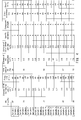
- FIG. 4 is a table summarizing the production conditions of each of the ceramic heater samples 1 to 25 and the results of evaluation described later.
- the ratio of the tungsten carbide powder mixed in step S110 to the total mass of the tungsten carbide powder and the silicon nitride powder was 67% by mass.
- the average particle diameter of the tungsten carbide powder used as a raw material was 0.7 ⁇ m, and the firing time in step S150 was 60 minutes.
- the ratio of the tungsten carbide powder mixed in step S110 to the total mass of the tungsten carbide powder and the silicon nitride powder was 73% by mass.
- the average particle diameter of the tungsten carbide powder used as a raw material was 0.5 ⁇ m
- the firing time in step S150 was 60 minutes.
- the average particle diameter of the tungsten carbide powder used as a raw material was 0.7 ⁇ m.
- the firing time in step S150 was 60 minutes for sample 3 and 120 minutes for sample 4.
- the average particle diameter of the tungsten carbide powder used as a raw material was 2.5 ⁇ m.
- the firing time in step S150 was 60 minutes for sample 5 and 120 minutes for sample 6.
- the average particle diameter of the tungsten carbide powder used as a raw material was 3.5 ⁇ m.
- the firing time in step S150 was 90 minutes for sample 7 and 150 minutes for sample 8.
- sample 9 the average particle diameter of the tungsten carbide powder used as a raw material was 5.1 ⁇ m, and the firing time in step S150 was 150 minutes.
- the ratio of the tungsten carbide powder mixed in step S110 to the total mass of the tungsten carbide powder and the silicon nitride powder was 77% by mass.
- the average particle diameter of the tungsten carbide powder used as a raw material was 0.5 ⁇ m
- the firing time in step S150 was 60 minutes.
- the average particle diameter of the tungsten carbide powder used as a raw material was 0.7 ⁇ m.
- the firing time in step S150 was 60 minutes for sample 11 and 90 minutes for sample 12.
- samples 13 and 14 the average particle diameter of the tungsten carbide powder used as a raw material was 2.5 ⁇ m.
- the firing time in step S150 was 60 minutes for sample 13 and 120 minutes for sample 14.
- the average particle diameter of the tungsten carbide powder used as a raw material was 3.5 ⁇ m.
- the firing time in step S150 was 60 minutes for sample 15 and 150 minutes for sample 16.
- the average particle diameter of the tungsten carbide powder used as a raw material was 5.1 ⁇ m, and the firing time in step S150 was 150 minutes.
- the ratio of the tungsten carbide powder mixed in step S110 to the total mass of the tungsten carbide powder and the silicon nitride powder was 85% by mass.
- the average particle diameter of the tungsten carbide powder used as a raw material was 0.7 ⁇ m.
- the firing time in step S150 was 90 minutes for sample 18 and 120 minutes for sample 19.
- the average particle diameter of the tungsten carbide powder used as a raw material was 2.5 ⁇ m.
- the firing time in step S150 was 60 minutes for sample 20 and 120 minutes for sample 21.
- the average particle diameter of the tungsten carbide powder used as a raw material was 3.5 ⁇ m.
- the firing time in step S150 was 90 minutes for sample 22 and 150 minutes for sample 23.
- the average particle diameter of the tungsten carbide powder used as a raw material was 5.1 ⁇ m, and the firing time in step S150 was 180 minutes.
- the ratio of the tungsten carbide powder mixed in step S110 to the total mass of the tungsten carbide powder and the silicon nitride powder was 90% by mass.
- the average particle diameter of the tungsten carbide powder used as a raw material was 3.0 ⁇ m, and the firing time in step S150 was 120 minutes.
- the firing temperature in step S150 was 1,800°C for all the samples.
- press-pressurization was started before the temperature reached 1,450°C, which is equal to or lower than the shrinkage start temperature (liquid phase formation start temperature) of the constituent materials, and then the pressurized state was maintained.
- the pressure of the nitrogen atmosphere in the furnace was set to 0.1 to 1.0 MPa to start pressurization by the pressurized atmosphere, and then this pressurized state was maintained.
- the ratio of the area of tungsten carbide portions in a cross section of the heat-generating resistor to the total area of the cross section was measured using an electron probe microanalyzer (EPMA, JXA-8800 manufactured by JEOL Ltd.) as described above. Specifically, for each sample, a cross section including the heat-generating resistor was obtained, then mirror-polished, and subjected to plasma etching treatment. Then the EPMA was used to identify WC regions in a field of view in which the cross section was magnified 3,000 times, and the total area of the identified WC regions was divided by the overall area of the field of view to determine the area ratio of WC.
- FIG. 2 described above shows an SEM image of sample 2.
- the average diameter of the tungsten carbide aggregates (the diameter of the WC aggregates) and the average diameter of the silicon nitride particles in a cross section of the heat-generating resistor were measured by the line intercept method, as described above. Specifically, on an image of a field of view in which the cross section of the heat-generating resistor was observed at 3,000 times , a plurality of parallel straight lines with a prescribed length were drawn, and the average of the lengths of intersecting portions of the straight lines that intersected particles (tungsten carbide aggregates or silicon nitride particles) was used as the average particle diameter. When particle diameters were measured, the number of particles intersected by the above straight lines was at least 50.
- the specific resistance of the heat-generating resistor of each sample was measured as follows. First, a test piece for resistance measurement was cut from each ceramic heater. Specifically, the test piece was cut from a portion of the heat-generating resistor with a constant cross sectional area (a portion other than the U-shaped bent portion of the heat-generating resistor). Then the length L (cm) of the test piece and the cross sectional area S (cm 2 ) of the heat-generating resistor were measured. The length of each test piece was set to 1 cm. The resistance value of the heat-generating resistor in the cut test piece was measured at room temperature (23 to 25°C) using a milliohm meter. Then the specific resistance value was computed from the measured resistance value using the following computational formula.
- each ceramic heater sample its transverse strength was measured as follows. To measure the transverse strength, the three-point bending strength of the sample was measured according to JIS R 1601. In this case, a span of 12 mm and a cross head speed of 0.5 mm/min were used. The diameter of each sample used for the measurement was 3.3 mm, and its overall length was 45 mm.
Landscapes
- Engineering & Computer Science (AREA)
- Chemical & Material Sciences (AREA)
- Combustion & Propulsion (AREA)
- Mechanical Engineering (AREA)
- General Engineering & Computer Science (AREA)
- Resistance Heating (AREA)
Applications Claiming Priority (1)
| Application Number | Priority Date | Filing Date | Title |
|---|---|---|---|
| JP2015121117A JP6608627B2 (ja) | 2015-06-16 | 2015-06-16 | セラミックヒータおよびグロープラグ |
Publications (3)
| Publication Number | Publication Date |
|---|---|
| EP3106754A2 true EP3106754A2 (de) | 2016-12-21 |
| EP3106754A3 EP3106754A3 (de) | 2017-03-15 |
| EP3106754B1 EP3106754B1 (de) | 2019-12-04 |
Family
ID=56551115
Family Applications (1)
| Application Number | Title | Priority Date | Filing Date |
|---|---|---|---|
| EP16174239.0A Active EP3106754B1 (de) | 2015-06-16 | 2016-06-13 | Keramische heizung und glühstift |
Country Status (2)
| Country | Link |
|---|---|
| EP (1) | EP3106754B1 (de) |
| JP (1) | JP6608627B2 (de) |
Families Citing this family (1)
| Publication number | Priority date | Publication date | Assignee | Title |
|---|---|---|---|---|
| JP7261949B2 (ja) * | 2018-10-26 | 2023-04-21 | 国立大学法人秋田大学 | WC-Si3N4系複合セラミックス及びその製造方法 |
Citations (3)
| Publication number | Priority date | Publication date | Assignee | Title |
|---|---|---|---|---|
| JP2002220285A (ja) | 2001-01-17 | 2002-08-09 | Ngk Spark Plug Co Ltd | 窒化珪素/炭化タングステン複合焼結体及びその製造方法 |
| JP2006127995A (ja) | 2004-10-29 | 2006-05-18 | Ngk Spark Plug Co Ltd | セラミックヒータ及びその製造方法並びにグロープラグ |
| JP2007335397A (ja) | 2006-05-18 | 2007-12-27 | Ngk Spark Plug Co Ltd | セラミックヒータ及びグロープラグ |
Family Cites Families (5)
| Publication number | Priority date | Publication date | Assignee | Title |
|---|---|---|---|---|
| JP4445595B2 (ja) * | 1995-09-12 | 2010-04-07 | 日本特殊陶業株式会社 | セラミックヒータ、セラミックグロープラグおよびその製造方法 |
| BR9700464A (pt) * | 1996-03-29 | 1998-11-03 | Ngk Spark Plug Co | Aquecedor cerâmico |
| JP3115254B2 (ja) * | 1996-03-29 | 2000-12-04 | 日本特殊陶業株式会社 | セラミックヒータ |
| JPH11214124A (ja) * | 1998-01-30 | 1999-08-06 | Kyocera Corp | セラミックヒータ |
| EP2869666B1 (de) * | 2012-06-29 | 2017-03-29 | Kyocera Corporation | Heizelement und damit versehene glühkerze |
-
2015
- 2015-06-16 JP JP2015121117A patent/JP6608627B2/ja active Active
-
2016
- 2016-06-13 EP EP16174239.0A patent/EP3106754B1/de active Active
Patent Citations (3)
| Publication number | Priority date | Publication date | Assignee | Title |
|---|---|---|---|---|
| JP2002220285A (ja) | 2001-01-17 | 2002-08-09 | Ngk Spark Plug Co Ltd | 窒化珪素/炭化タングステン複合焼結体及びその製造方法 |
| JP2006127995A (ja) | 2004-10-29 | 2006-05-18 | Ngk Spark Plug Co Ltd | セラミックヒータ及びその製造方法並びにグロープラグ |
| JP2007335397A (ja) | 2006-05-18 | 2007-12-27 | Ngk Spark Plug Co Ltd | セラミックヒータ及びグロープラグ |
Also Published As
| Publication number | Publication date |
|---|---|
| EP3106754B1 (de) | 2019-12-04 |
| JP6608627B2 (ja) | 2019-11-20 |
| EP3106754A3 (de) | 2017-03-15 |
| JP2017004915A (ja) | 2017-01-05 |
Similar Documents
| Publication | Publication Date | Title |
|---|---|---|
| JP5989896B2 (ja) | セラミックヒータ | |
| WO2009096477A1 (ja) | セラミックヒータおよびグロープラグ | |
| US9702559B2 (en) | Heater and glow plug provided with same | |
| JP2007335397A (ja) | セラミックヒータ及びグロープラグ | |
| JP5876566B2 (ja) | ヒータおよびこれを備えたグロープラグ | |
| JP5280877B2 (ja) | セラミックヒータ及びグロープラグ | |
| JP5075477B2 (ja) | セラミックヒータ及びグロープラグ | |
| US9291144B2 (en) | Heater and glow plug including the same | |
| EP3106754B1 (de) | Keramische heizung und glühstift | |
| EP2704518B1 (de) | Heizelement und glühkerze damit | |
| WO2014069480A1 (ja) | ヒータおよびこれを備えたグロープラグ | |
| JP2008235034A (ja) | セラミックヒータ及びグロープラグ | |
| JP3078418B2 (ja) | セラミック発熱体 | |
| EP2623866B1 (de) | Heizung und glühstift damit | |
| JP6753711B2 (ja) | セラミックヒータおよびグロープラグ | |
| JP2004061041A (ja) | セラミックグロープラグ | |
| EP2869666B1 (de) | Heizelement und damit versehene glühkerze | |
| JP2010181125A (ja) | セラミックヒータ及びグロープラグ | |
| KR0148449B1 (ko) | 나선형 발열체 팁을 갖는 세라믹 글로우 플러그 | |
| JP6392004B2 (ja) | ヒータおよびグロープラグ | |
| JP4597352B2 (ja) | セラミックヒータ | |
| JP2004146356A (ja) | セラミックヒータ | |
| JP2001173953A (ja) | セラミックグロープラグ | |
| JP2004259611A (ja) | セラミックヒータ | |
| JP2001284017A (ja) | セラミックヒータ及びそれを備えるグロープラグ |
Legal Events
| Date | Code | Title | Description |
|---|---|---|---|
| PUAI | Public reference made under article 153(3) epc to a published international application that has entered the european phase |
Free format text: ORIGINAL CODE: 0009012 |
|
| STAA | Information on the status of an ep patent application or granted ep patent |
Free format text: STATUS: THE APPLICATION HAS BEEN PUBLISHED |
|
| AK | Designated contracting states |
Kind code of ref document: A2 Designated state(s): AL AT BE BG CH CY CZ DE DK EE ES FI FR GB GR HR HU IE IS IT LI LT LU LV MC MK MT NL NO PL PT RO RS SE SI SK SM TR |
|
| AX | Request for extension of the european patent |
Extension state: BA ME |
|
| PUAL | Search report despatched |
Free format text: ORIGINAL CODE: 0009013 |
|
| AK | Designated contracting states |
Kind code of ref document: A3 Designated state(s): AL AT BE BG CH CY CZ DE DK EE ES FI FR GB GR HR HU IE IS IT LI LT LU LV MC MK MT NL NO PL PT RO RS SE SI SK SM TR |
|
| AX | Request for extension of the european patent |
Extension state: BA ME |
|
| RIC1 | Information provided on ipc code assigned before grant |
Ipc: F23Q 7/00 20060101AFI20170203BHEP |
|
| STAA | Information on the status of an ep patent application or granted ep patent |
Free format text: STATUS: REQUEST FOR EXAMINATION WAS MADE |
|
| 17P | Request for examination filed |
Effective date: 20170622 |
|
| RBV | Designated contracting states (corrected) |
Designated state(s): AL AT BE BG CH CY CZ DE DK EE ES FI FR GB GR HR HU IE IS IT LI LT LU LV MC MK MT NL NO PL PT RO RS SE SI SK SM TR |
|
| GRAP | Despatch of communication of intention to grant a patent |
Free format text: ORIGINAL CODE: EPIDOSNIGR1 |
|
| STAA | Information on the status of an ep patent application or granted ep patent |
Free format text: STATUS: GRANT OF PATENT IS INTENDED |
|
| INTG | Intention to grant announced |
Effective date: 20190821 |
|
| GRAS | Grant fee paid |
Free format text: ORIGINAL CODE: EPIDOSNIGR3 |
|
| GRAA | (expected) grant |
Free format text: ORIGINAL CODE: 0009210 |
|
| STAA | Information on the status of an ep patent application or granted ep patent |
Free format text: STATUS: THE PATENT HAS BEEN GRANTED |
|
| AK | Designated contracting states |
Kind code of ref document: B1 Designated state(s): AL AT BE BG CH CY CZ DE DK EE ES FI FR GB GR HR HU IE IS IT LI LT LU LV MC MK MT NL NO PL PT RO RS SE SI SK SM TR |
|
| REG | Reference to a national code |
Ref country code: GB Ref legal event code: FG4D |
|
| REG | Reference to a national code |
Ref country code: CH Ref legal event code: EP |
|
| REG | Reference to a national code |
Ref country code: AT Ref legal event code: REF Ref document number: 1209876 Country of ref document: AT Kind code of ref document: T Effective date: 20191215 |
|
| REG | Reference to a national code |
Ref country code: DE Ref legal event code: R096 Ref document number: 602016025379 Country of ref document: DE |
|
| REG | Reference to a national code |
Ref country code: IE Ref legal event code: FG4D |
|
| REG | Reference to a national code |
Ref country code: NL Ref legal event code: MP Effective date: 20191204 |
|
| REG | Reference to a national code |
Ref country code: LT Ref legal event code: MG4D |
|
| PG25 | Lapsed in a contracting state [announced via postgrant information from national office to epo] |
Ref country code: LT Free format text: LAPSE BECAUSE OF FAILURE TO SUBMIT A TRANSLATION OF THE DESCRIPTION OR TO PAY THE FEE WITHIN THE PRESCRIBED TIME-LIMIT Effective date: 20191204 Ref country code: GR Free format text: LAPSE BECAUSE OF FAILURE TO SUBMIT A TRANSLATION OF THE DESCRIPTION OR TO PAY THE FEE WITHIN THE PRESCRIBED TIME-LIMIT Effective date: 20200305 Ref country code: FI Free format text: LAPSE BECAUSE OF FAILURE TO SUBMIT A TRANSLATION OF THE DESCRIPTION OR TO PAY THE FEE WITHIN THE PRESCRIBED TIME-LIMIT Effective date: 20191204 Ref country code: BG Free format text: LAPSE BECAUSE OF FAILURE TO SUBMIT A TRANSLATION OF THE DESCRIPTION OR TO PAY THE FEE WITHIN THE PRESCRIBED TIME-LIMIT Effective date: 20200304 Ref country code: NO Free format text: LAPSE BECAUSE OF FAILURE TO SUBMIT A TRANSLATION OF THE DESCRIPTION OR TO PAY THE FEE WITHIN THE PRESCRIBED TIME-LIMIT Effective date: 20200304 Ref country code: SE Free format text: LAPSE BECAUSE OF FAILURE TO SUBMIT A TRANSLATION OF THE DESCRIPTION OR TO PAY THE FEE WITHIN THE PRESCRIBED TIME-LIMIT Effective date: 20191204 Ref country code: LV Free format text: LAPSE BECAUSE OF FAILURE TO SUBMIT A TRANSLATION OF THE DESCRIPTION OR TO PAY THE FEE WITHIN THE PRESCRIBED TIME-LIMIT Effective date: 20191204 |
|
| PG25 | Lapsed in a contracting state [announced via postgrant information from national office to epo] |
Ref country code: RS Free format text: LAPSE BECAUSE OF FAILURE TO SUBMIT A TRANSLATION OF THE DESCRIPTION OR TO PAY THE FEE WITHIN THE PRESCRIBED TIME-LIMIT Effective date: 20191204 Ref country code: HR Free format text: LAPSE BECAUSE OF FAILURE TO SUBMIT A TRANSLATION OF THE DESCRIPTION OR TO PAY THE FEE WITHIN THE PRESCRIBED TIME-LIMIT Effective date: 20191204 |
|
| PG25 | Lapsed in a contracting state [announced via postgrant information from national office to epo] |
Ref country code: AL Free format text: LAPSE BECAUSE OF FAILURE TO SUBMIT A TRANSLATION OF THE DESCRIPTION OR TO PAY THE FEE WITHIN THE PRESCRIBED TIME-LIMIT Effective date: 20191204 |
|
| PG25 | Lapsed in a contracting state [announced via postgrant information from national office to epo] |
Ref country code: NL Free format text: LAPSE BECAUSE OF FAILURE TO SUBMIT A TRANSLATION OF THE DESCRIPTION OR TO PAY THE FEE WITHIN THE PRESCRIBED TIME-LIMIT Effective date: 20191204 Ref country code: PT Free format text: LAPSE BECAUSE OF FAILURE TO SUBMIT A TRANSLATION OF THE DESCRIPTION OR TO PAY THE FEE WITHIN THE PRESCRIBED TIME-LIMIT Effective date: 20200429 Ref country code: CZ Free format text: LAPSE BECAUSE OF FAILURE TO SUBMIT A TRANSLATION OF THE DESCRIPTION OR TO PAY THE FEE WITHIN THE PRESCRIBED TIME-LIMIT Effective date: 20191204 Ref country code: ES Free format text: LAPSE BECAUSE OF FAILURE TO SUBMIT A TRANSLATION OF THE DESCRIPTION OR TO PAY THE FEE WITHIN THE PRESCRIBED TIME-LIMIT Effective date: 20191204 Ref country code: RO Free format text: LAPSE BECAUSE OF FAILURE TO SUBMIT A TRANSLATION OF THE DESCRIPTION OR TO PAY THE FEE WITHIN THE PRESCRIBED TIME-LIMIT Effective date: 20191204 Ref country code: EE Free format text: LAPSE BECAUSE OF FAILURE TO SUBMIT A TRANSLATION OF THE DESCRIPTION OR TO PAY THE FEE WITHIN THE PRESCRIBED TIME-LIMIT Effective date: 20191204 |
|
| PG25 | Lapsed in a contracting state [announced via postgrant information from national office to epo] |
Ref country code: SK Free format text: LAPSE BECAUSE OF FAILURE TO SUBMIT A TRANSLATION OF THE DESCRIPTION OR TO PAY THE FEE WITHIN THE PRESCRIBED TIME-LIMIT Effective date: 20191204 Ref country code: IS Free format text: LAPSE BECAUSE OF FAILURE TO SUBMIT A TRANSLATION OF THE DESCRIPTION OR TO PAY THE FEE WITHIN THE PRESCRIBED TIME-LIMIT Effective date: 20200404 Ref country code: SM Free format text: LAPSE BECAUSE OF FAILURE TO SUBMIT A TRANSLATION OF THE DESCRIPTION OR TO PAY THE FEE WITHIN THE PRESCRIBED TIME-LIMIT Effective date: 20191204 |
|
| REG | Reference to a national code |
Ref country code: DE Ref legal event code: R097 Ref document number: 602016025379 Country of ref document: DE |
|
| REG | Reference to a national code |
Ref country code: AT Ref legal event code: MK05 Ref document number: 1209876 Country of ref document: AT Kind code of ref document: T Effective date: 20191204 |
|
| PLBE | No opposition filed within time limit |
Free format text: ORIGINAL CODE: 0009261 |
|
| STAA | Information on the status of an ep patent application or granted ep patent |
Free format text: STATUS: NO OPPOSITION FILED WITHIN TIME LIMIT |
|
| PG25 | Lapsed in a contracting state [announced via postgrant information from national office to epo] |
Ref country code: DK Free format text: LAPSE BECAUSE OF FAILURE TO SUBMIT A TRANSLATION OF THE DESCRIPTION OR TO PAY THE FEE WITHIN THE PRESCRIBED TIME-LIMIT Effective date: 20191204 |
|
| 26N | No opposition filed |
Effective date: 20200907 |
|
| PG25 | Lapsed in a contracting state [announced via postgrant information from national office to epo] |
Ref country code: PL Free format text: LAPSE BECAUSE OF FAILURE TO SUBMIT A TRANSLATION OF THE DESCRIPTION OR TO PAY THE FEE WITHIN THE PRESCRIBED TIME-LIMIT Effective date: 20191204 Ref country code: SI Free format text: LAPSE BECAUSE OF FAILURE TO SUBMIT A TRANSLATION OF THE DESCRIPTION OR TO PAY THE FEE WITHIN THE PRESCRIBED TIME-LIMIT Effective date: 20191204 Ref country code: AT Free format text: LAPSE BECAUSE OF FAILURE TO SUBMIT A TRANSLATION OF THE DESCRIPTION OR TO PAY THE FEE WITHIN THE PRESCRIBED TIME-LIMIT Effective date: 20191204 |
|
| PG25 | Lapsed in a contracting state [announced via postgrant information from national office to epo] |
Ref country code: MC Free format text: LAPSE BECAUSE OF FAILURE TO SUBMIT A TRANSLATION OF THE DESCRIPTION OR TO PAY THE FEE WITHIN THE PRESCRIBED TIME-LIMIT Effective date: 20191204 Ref country code: IT Free format text: LAPSE BECAUSE OF FAILURE TO SUBMIT A TRANSLATION OF THE DESCRIPTION OR TO PAY THE FEE WITHIN THE PRESCRIBED TIME-LIMIT Effective date: 20191204 |
|
| REG | Reference to a national code |
Ref country code: CH Ref legal event code: PL |
|
| GBPC | Gb: european patent ceased through non-payment of renewal fee |
Effective date: 20200613 |
|
| PG25 | Lapsed in a contracting state [announced via postgrant information from national office to epo] |
Ref country code: LU Free format text: LAPSE BECAUSE OF NON-PAYMENT OF DUE FEES Effective date: 20200613 |
|
| REG | Reference to a national code |
Ref country code: BE Ref legal event code: MM Effective date: 20200630 |
|
| PG25 | Lapsed in a contracting state [announced via postgrant information from national office to epo] |
Ref country code: CH Free format text: LAPSE BECAUSE OF NON-PAYMENT OF DUE FEES Effective date: 20200630 Ref country code: LI Free format text: LAPSE BECAUSE OF NON-PAYMENT OF DUE FEES Effective date: 20200630 Ref country code: FR Free format text: LAPSE BECAUSE OF NON-PAYMENT OF DUE FEES Effective date: 20200630 Ref country code: IE Free format text: LAPSE BECAUSE OF NON-PAYMENT OF DUE FEES Effective date: 20200613 Ref country code: GB Free format text: LAPSE BECAUSE OF NON-PAYMENT OF DUE FEES Effective date: 20200613 |
|
| PG25 | Lapsed in a contracting state [announced via postgrant information from national office to epo] |
Ref country code: BE Free format text: LAPSE BECAUSE OF NON-PAYMENT OF DUE FEES Effective date: 20200630 |
|
| PG25 | Lapsed in a contracting state [announced via postgrant information from national office to epo] |
Ref country code: TR Free format text: LAPSE BECAUSE OF FAILURE TO SUBMIT A TRANSLATION OF THE DESCRIPTION OR TO PAY THE FEE WITHIN THE PRESCRIBED TIME-LIMIT Effective date: 20191204 Ref country code: MT Free format text: LAPSE BECAUSE OF FAILURE TO SUBMIT A TRANSLATION OF THE DESCRIPTION OR TO PAY THE FEE WITHIN THE PRESCRIBED TIME-LIMIT Effective date: 20191204 Ref country code: CY Free format text: LAPSE BECAUSE OF FAILURE TO SUBMIT A TRANSLATION OF THE DESCRIPTION OR TO PAY THE FEE WITHIN THE PRESCRIBED TIME-LIMIT Effective date: 20191204 |
|
| PG25 | Lapsed in a contracting state [announced via postgrant information from national office to epo] |
Ref country code: MK Free format text: LAPSE BECAUSE OF FAILURE TO SUBMIT A TRANSLATION OF THE DESCRIPTION OR TO PAY THE FEE WITHIN THE PRESCRIBED TIME-LIMIT Effective date: 20191204 |
|
| REG | Reference to a national code |
Ref country code: DE Ref legal event code: R081 Ref document number: 602016025379 Country of ref document: DE Owner name: NITERRA CO., LTD., NAGOYA-SHI, JP Free format text: FORMER OWNER: NGK SPARK PLUG CO., LTD., NAGOYA-SHI, AICHI-KEN, JP |
|
| PGFP | Annual fee paid to national office [announced via postgrant information from national office to epo] |
Ref country code: DE Payment date: 20240502 Year of fee payment: 9 |