EP3100892A1 - Schaltvorrichtung für ein fahrzeug - Google Patents
Schaltvorrichtung für ein fahrzeug Download PDFInfo
- Publication number
- EP3100892A1 EP3100892A1 EP16171816.8A EP16171816A EP3100892A1 EP 3100892 A1 EP3100892 A1 EP 3100892A1 EP 16171816 A EP16171816 A EP 16171816A EP 3100892 A1 EP3100892 A1 EP 3100892A1
- Authority
- EP
- European Patent Office
- Prior art keywords
- shift
- detent pin
- detent
- shaft portion
- cylindrical shaft
- Prior art date
- Legal status (The legal status is an assumption and is not a legal conclusion. Google has not performed a legal analysis and makes no representation as to the accuracy of the status listed.)
- Granted
Links
Images


Classifications
-
- F—MECHANICAL ENGINEERING; LIGHTING; HEATING; WEAPONS; BLASTING
- F16—ENGINEERING ELEMENTS AND UNITS; GENERAL MEASURES FOR PRODUCING AND MAINTAINING EFFECTIVE FUNCTIONING OF MACHINES OR INSTALLATIONS; THERMAL INSULATION IN GENERAL
- F16H—GEARING
- F16H59/00—Control inputs to control units of change-speed- or reversing-gearings for conveying rotary motion
- F16H59/02—Selector apparatus
- F16H59/08—Range selector apparatus
- F16H59/10—Range selector apparatus comprising levers
-
- F—MECHANICAL ENGINEERING; LIGHTING; HEATING; WEAPONS; BLASTING
- F16—ENGINEERING ELEMENTS AND UNITS; GENERAL MEASURES FOR PRODUCING AND MAINTAINING EFFECTIVE FUNCTIONING OF MACHINES OR INSTALLATIONS; THERMAL INSULATION IN GENERAL
- F16H—GEARING
- F16H59/00—Control inputs to control units of change-speed- or reversing-gearings for conveying rotary motion
- F16H59/02—Selector apparatus
-
- B—PERFORMING OPERATIONS; TRANSPORTING
- B60—VEHICLES IN GENERAL
- B60K—ARRANGEMENT OR MOUNTING OF PROPULSION UNITS OR OF TRANSMISSIONS IN VEHICLES; ARRANGEMENT OR MOUNTING OF PLURAL DIVERSE PRIME-MOVERS IN VEHICLES; AUXILIARY DRIVES FOR VEHICLES; INSTRUMENTATION OR DASHBOARDS FOR VEHICLES; ARRANGEMENTS IN CONNECTION WITH COOLING, AIR INTAKE, GAS EXHAUST OR FUEL SUPPLY OF PROPULSION UNITS IN VEHICLES
- B60K20/00—Arrangement or mounting of change-speed gearing control devices in vehicles
- B60K20/02—Arrangement or mounting of change-speed gearing control devices in vehicles of initiating means
-
- F—MECHANICAL ENGINEERING; LIGHTING; HEATING; WEAPONS; BLASTING
- F16—ENGINEERING ELEMENTS AND UNITS; GENERAL MEASURES FOR PRODUCING AND MAINTAINING EFFECTIVE FUNCTIONING OF MACHINES OR INSTALLATIONS; THERMAL INSULATION IN GENERAL
- F16H—GEARING
- F16H59/00—Control inputs to control units of change-speed- or reversing-gearings for conveying rotary motion
- F16H59/02—Selector apparatus
- F16H59/0278—Constructional features of the selector lever, e.g. grip parts, mounting or manufacturing
-
- F—MECHANICAL ENGINEERING; LIGHTING; HEATING; WEAPONS; BLASTING
- F16—ENGINEERING ELEMENTS AND UNITS; GENERAL MEASURES FOR PRODUCING AND MAINTAINING EFFECTIVE FUNCTIONING OF MACHINES OR INSTALLATIONS; THERMAL INSULATION IN GENERAL
- F16H—GEARING
- F16H61/00—Control functions within control units of change-speed- or reversing-gearings for conveying rotary motion ; Control of exclusively fluid gearing, friction gearing, gearings with endless flexible members or other particular types of gearing
- F16H61/22—Locking of the control input devices
-
- F—MECHANICAL ENGINEERING; LIGHTING; HEATING; WEAPONS; BLASTING
- F16—ENGINEERING ELEMENTS AND UNITS; GENERAL MEASURES FOR PRODUCING AND MAINTAINING EFFECTIVE FUNCTIONING OF MACHINES OR INSTALLATIONS; THERMAL INSULATION IN GENERAL
- F16H—GEARING
- F16H59/00—Control inputs to control units of change-speed- or reversing-gearings for conveying rotary motion
- F16H59/02—Selector apparatus
- F16H2059/026—Details or special features of the selector casing or lever support
-
- F—MECHANICAL ENGINEERING; LIGHTING; HEATING; WEAPONS; BLASTING
- F16—ENGINEERING ELEMENTS AND UNITS; GENERAL MEASURES FOR PRODUCING AND MAINTAINING EFFECTIVE FUNCTIONING OF MACHINES OR INSTALLATIONS; THERMAL INSULATION IN GENERAL
- F16H—GEARING
- F16H59/00—Control inputs to control units of change-speed- or reversing-gearings for conveying rotary motion
- F16H59/02—Selector apparatus
- F16H59/0278—Constructional features of the selector lever, e.g. grip parts, mounting or manufacturing
- F16H2059/0282—Lever handles with lock mechanisms, e.g. for allowing selection of reverse gear or releasing lever from park position
Definitions
- the invention relates to a shift device for a vehicle and, more particularly, to a technique for preventing or reducing a pivot of a detent pin due to contact with a shift lock member.
- the shift device includes a shift lever.
- the shift lever includes a cylindrical shaft portion and a shift knob.
- the proximal end of the cylindrical shaft portion is pivotably supported inside a housing.
- the shift knob is fixed to the distal end of the cylindrical shaft portion.
- the cylindrical shaft portion has elongated holes. Each of the elongated holes extends through the peripheral wall of the cylindrical shaft portion, and is elongated in the longitudinal direction of the cylindrical shaft portion.
- a detent pin is inserted through the elongated holes such that both ends of the detent pin protrude from the elongated holes.
- An operating button is provided in the shift knob.
- a detent rod transmits operating force of the operating button to the detent pin.
- the detent rod is inserted in the cylindrical shaft portion.
- This is, for example, a shift device for a vehicle, described in Japanese Patent Application Publication No. 2012-56430 ( JP 2012-56430 A ).
- the shift device for a vehicle described in JP 2012-56430 A
- the detent pin in a state where an engaging protrusion protruding from the detent rod toward the detent pin is engaged with an engaging hole provided in the detent pin, the detent pin is constantly urged toward the detent rod by a spring.
- Both ends of the detent pin respectively protruding from the elongated holes of the cylindrical shaft portion each are engaged with any one of detent grooves that are provided in each of detent plates provided in the housing and that correspond to shift positions.
- the shift lever is positioned to the any one of the shift positions.
- a shift lock device for a vehicle.
- the shift lock device restricts releasing operation for releasing engagement of the detent pin with the detent groove corresponding to, for example, a P position as a result of contact of a shift lock member with one end of the detent pin to block movement of the detent pin.
- the detent pin urged by the spring toward the detent rod may pivot on the contact position with the shift lock member as a fulcrum to be inclined by operating force of an operating button, transmitted via the detent rod. Because of such a pivot of the detent pin due to activation of the shift lock device, there is a possibility that the durability of the shift device decreases.
- the invention provides a shift device for a vehicle, which prevents or reduces a pivot of a detent pin due to contact with a shift lock member.
- An aspect of the invention provides a shift device for a vehicle.
- the shift device includes a housing and a shift lever.
- the shift lever includes a cylindrical shaft portion of which a proximal end is pivotably supported inside the housing, the cylindrical shaft portion having elongated holes that extend through a peripheral wall of the cylindrical shaft portion and that are elongated in a longitudinal direction of the cylindrical shaft portion, a shift knob fixed to a distal end of the cylindrical shaft portion, a detent pin inserted through the elongated holes in a state where both ends of the detent pin protrude from the corresponding elongated holes, a detent rod inserted in the cylindrical shaft portion, the detent rod being configured to transmit operating force of an operating button provided in the shift knob to the detent pin, and a shift lock member.
- the detent pin is fitted to the detent rod.
- the shift lock member contacts with one end of the detent pin to block movement of the detent pin.
- a support protrusion that protrudes toward the proximal end of the cylindrical shaft portion is provided at the other end of the detent pin. The support protrusion contacts with the cylindrical shaft portion and restricts an inclination of the detent pin due to contact between the shift lock member and the detent pin.
- the support protrusion that contacts with the cylindrical shaft portion to restrict an inclination of the detent pin due to contact between the shift lock member and the detent pin protrudes from the other end of the detent pin toward the proximal end of the cylindrical shaft portion.
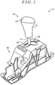
- FIG. 1 is a perspective view of a shift device 10 for a vehicle according to the embodiment of the invention.
- the shift device 10 includes a shift lever 18, a bearing member (not shown), a control lever (not shown), and a housing 20.
- the shift lever 18 includes a support portion 36, a lever pipe 14, and a shift knob 16.
- the support portion 36 is pivotably supported via a spherical proximal end 12 (shown in FIG. 2 ).
- the proximal end of the lever pipe 14 is supported by the support portion 36.
- the shift knob 16 is fixed to the distal end of the lever pipe 14.
- the bearing member has a spherical bearing surface that receives the spherical proximal end 12 and that is slidable on the spherical proximal end 12.
- the control lever is assembled to the shift lever 18, and transmits operation of the shift lever 18 in a shift direction to an automatic transmission via a cable (not shown).
- the housing 20 accommodates the bearing member and the lower end of the shift lever 18 and control lever, and is fixed to a floor, or the like, in a vehicle cabin.
- the support portion 36 of which the spherical proximal end 12 is pivotably supported inside the housing 20 and the lever pipe 14 of which the proximal end is fixed inside the support portion 36 function as a cylindrical shaft portion according to the invention.
- the shift lever 18 is provided upright on the housing 20 so as to be pivotable in the shift direction or a select direction around the center of the spherical proximal end 12 slidably supported by the bearing member.
- the housing 20 includes a shift gate 24 as its upper wall face.
- the shift gate 24 is a plate-shaped member having a guide slot 22.
- the guide slot 22 allows the lever pipe 14 of the shift lever 18 to extend therethrough, and guides the shift lever 18 to any one of shift positions, such as a parking position (P position), a reverse position (R position), a neutral position (N position) and a drive position (D position).
- Detent plates 26 are provided in the housing 20 as shown in FIG. 4 . Each of the detent plates 26 has a wall shape. The detent plates 26 are used to regulate a shift operation, for example, an operation to change the shift position between the parking position and the reverse position, that is, a non-parking position, by placing the shift lever 18 to any one of the above-described shift positions.
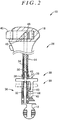
- FIG. 2 is a cross-sectional view of the shift lever 18 accommodated in the housing 20 of the shift device 10.
- the shift lever 18 includes an assembly 28 (lever subassy), a detent pin 30, a spring 32, a detent rod 34, and the shift knob 16.
- the assembly 28 includes the cylindrical lever pipe 14, the support portion 36 and the spherical proximal end 12.
- the lever pipe 14 is made of resin.
- the support portion 36 includes a cylindrical hole and a columnar hole. The cylindrical hole fixes the lever pipe 14 inside by allowing the proximal end of the lever pipe 14 to be fitted therein.
- the columnar hole has an annular end face that is provided on the radially inner side of the cylindrical hole and that supports one end of the spring 32.
- the spring 32 has an outside diameter smaller than the inside diameter of the lever pipe 14.
- the spherical proximal end 12 is formed on the vehicle lower side of the support portion 36.
- FIG. 3 is an enlarged perspective view of part of the assembly 28.
- the assembly 28 has a pair of elongated holes 39 for the detent pin, which are used to insert the detent pin 30 in a direction perpendicular to the assembly 28.
- Each of the pair of elongated holes 39 is formed of a lever pipe-side elongated hole 37 and a support portion-side elongated hole 38 so as to be elongated in the axial direction of the lever pipe 14.
- the lever pipe-side elongated hole 37 extends through the peripheral wall of the lever pipe 14 in a direction perpendicular to the axial direction of the lever pipe 14.
- the support portion-side elongated hole 38 extends through the peripheral wall of the support portion 36, facing the lever pipe-side elongated hole 37.
- the detent pin 30 is inserted in the elongated holes 39 in a state where both ends of the detent pin 30 protrude from the corresponding elongated holes 39.
- the detent pin 30 includes a fitting protrusion 42 and a support protrusion 43.
- the fitting protrusion 42 is protruded toward the detent rod 34, that is, the upward side in FIG. 2 .
- the support protrusion 43 is protruded in an arm shape toward the proximal end of the lever pipe 14 at the other end of both ends protruded from the elongated holes 39 across the fitting protrusion 42 from one end with which a shift lock link 56 (described later) contacts, and supports the detent pin 30 by contact with the support portion 36 that fits the proximal end of the lever pipe 14 therein and supports the proximal end of the lever pipe 14.
- the protruded end of the support protrusion 43 is moved inside a recessed groove 44 that is provided in the support portion 36 below the corresponding elongated hole 39 and that is elongated in the axial direction of the lever pipe 14.
- the shift knob 16 includes a knob button 45.
- the knob button 45 functions as an operating button provided so as to be movable in a direction perpendicular to the axial direction of the lever pipe 14 and urged by a spring (not shown) in a protruded direction.
- the detent rod 34 includes a hemispherical surface 48 at its upper end and a fitting hole 50 at its lower end. The hemispherical surface 48 is in contact with a cam face 46 of the knob button 45.
- the fitting protrusion 42 of the detent pin 30 is fitted to the fitting hole 50.
- the detent rod 34 is inserted in the lever pipe 14 and fitted to the fitting protrusion 42 of the detent pin 30 so as to be able to transmit operating force of the knob button 45 provided in the shift knob 16 to the detent pin 30.
- the detent pin 30 is constantly urged by the spring 32 arranged at the support portion 36 of the assembly 28 toward the detent rod 34 in a direction opposite to the direction of the operating force of the knob button 45. Both ends of the detent pin 30 are respectively engaged with the detent plates 26 (described later).
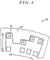
- FIG. 4 is a view that shows one of the detent plates 26 provided in the housing 20.
- a shift operation direction of the shift lever 18 is indicated by the horizontal arrow, and an actuating direction of the detent pin 30 is indicated by the vertical arrow.
- Each detent plate 26 includes detent grooves 52 and a regulating wall 54.
- the detent grooves 52 respectively correspond to the shift positions, that is, the parking position (P position), the reverse position (R position), the neutral position (N position) and the drive position (D position), with which the detent pin 30 is engaged.
- the regulating wall 54 regulates shift operation of the shift lever 18, which is indicated by the horizontal arrow in FIG. 4 .
- the knob button 45 When the knob button 45 is not operated, the detent pin 30 is engaged with the detent groove 52 corresponding to any one of the shift positions of each detent plate 26 by the urging force of the spring 32.
- the regulating wall 54 restricts movement of the detent pin 30 between the parking position and the reverse position and movement of the detent pin 30 from the neutral position to the reverse position to regulate corresponding shift operations of the shift lever 18 when the knob button 45 is not operated.
- the detent pin 30 to which the operating force of the knob button 45 is transmitted via the detent rod 34 is moved to any one of the positions indicated by the squares at the lower side in FIG. 4 and corresponding to the detent groove 52 of each shift position, and is allowed to move in the shift operation direction.
- an operation to change the shift position between the parking position and the reverse position and an operation to change the shift position of the shift lever 18 from the neutral position to the reverse position are enabled.
- the detent pin 30 is moved toward the detent rod 34 by the urging force of the spring 32, and is engaged with the pair of detent grooves 52 corresponding to any changed one of the shift positions.
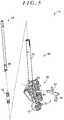
- FIG. 5 is a perspective view that separately shows the assembly 28, the detent rod 34, the detent pin 30 and the spring 32 before assembling, which constitute the shift lever 18 accommodated in the housing 20 of the shift device 10.
- the shift lever 18 is assembled in accordance with the following steps. Initially, the spring 32 is inserted from the upper opening of the lever pipe 14 of the assembly 28, and then the lower end of the spring 32 is supported by the annular end face of the support portion 36.
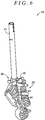
- FIG. 6 is a perspective view of the shift lever 18 in a state where the spring 32 and the detent pin 30 are arranged in the assembly 28.
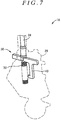
- FIG. 7 is a view that shows an assembled state of the spring 32, detent pin 30 and detent rod 34 inside the assembly 28 of the shift lever 18.
- the assembly 28 is indicated by the dashed line.
- the shift device 10 includes a shift lock device.
- the shift lock device restricts releasing operation for releasing engagement of the detent pin 30 with the detent grooves 52 corresponding to the P position, and cancels the restriction on the releasing operation interlocking with brake operation of the vehicle.
- FIG. 8 is a cross-sectional view taken along the axis of the lever pipe 14, showing a state where the above-described releasing operation of the shift lever 18 is restricted in response to activation of the shift lock device.
- the shift lock device includes the shift lock link 56.
- the shift lock link 56 is movable between a lock position at which the releasing operation is restricted and a non-lock position at which a restriction on the releasing operation is cancelled.
- the shift lock link 56 serves as a shift lock member according to the invention.
- the shift lock link 56 contacts with one end of the detent pin 30 across the fitting protrusion 42 from the other end at which the support protrusion 43 is provided, and blocks movement of the detent pin 30 away from the detent rod 34, that is, downward in FIG. 8 when operating force of operation of the knob button 45, indicated by the arrow, via the detent rod 34 is transmitted to the detent pin 30.
- the shift lever 18 is not allowed to move from the P position.
- reaction force in a direction opposite to moment that is received as a result of operating force of the knob button 45 on the contact position with the shift lock link 56 as a fulcrum is applied to the detent pin 30, that is, the reaction force is applied from the inner wall face of the recessed groove 44, provided in the support portion 36 that fixes the lever pipe 14, to the support protrusion 43 that contacts with the inner wall face of the recessed groove 44.
- a pivot of the detent pin 30 due to contact with the shift lock link 56 is prevented or reduced, and an inclination of the detent pin 30 is restricted, so the position of the detent pin 30 at the time when the detent pin 30 is assembled is maintained.
- FIG. 9 is a cross-sectional view taken along the axis of the lever pipe 14, showing a relevant portion of a shift lever 112 of a shift device 110 for a vehicle.
- the shift device 110 has a similar configuration to that of the above-described shift device 10 except that the support protrusion 43 that contacts with the recessed groove 44 of the support portion 36 that fixes the lever pipe 14 is not provided in a detent pin 114 provided in the shift lever 112.
- a state of the detent pin 114 and the detent rod 34 at the time when the releasing operation of the shift lever 112 of which the shift position is, for example, placed at the P position is restricted by the shift lock device is indicated by the dashed line.
- the shift lock link 56 contacts with one end of the detent pin 114, and blocks movement of the detent pin 114 away from the detent rod 34, that is, downward in FIG. 9 .
- the knob button 45 is operated with a larger force and excessive operating force of the knob button 45 in the direction indicated by the arrow is transmitted to the detent pin 114 via the detent rod 34, the detent pin 114 receives moment resulting from the operating force of the knob button 45 on the shift lock link 56 as a fulcrum, and pivots to be inclined in the arrow direction in FIG. 9 .
- the support protrusion 43 that contacts with the recessed groove 44 of the support portion 36 that fixes the lever pipe 14 and that restricts an inclination of the detent pin 30 due to contact between the shift lock link 56 and the detent pin 30 protrudes toward the proximal end of the lever pipe 14 at the other end of the detent pin 30 across the fitting protrusion 42 from the one end that contacts with the shift lock link 56.
- an inclination of the detent pin 30 due to contact with the shift lock link 56 resulting from operation of the knob button 45 during activation of the shift lock device that restricts the releasing operation of the detent pin 30 is prevented or reduced by the support protrusion 43 provided in the detent pin 30. For this reason, without the necessity for fixing the detent pin 30 to the detent rod 34 by swaging or press-fitting in a special facility, a pivot or inclination of the detent pin 30 due to contact with the shift lock link 56 is prevented or reduced.
- the support protrusion 43 of the detent pin 30 of the shift lever 18 indirectly contacts with the lever pipe 14 via the inner wall face of the recessed groove 44 of the support portion 36 that fixes the lever pipe 14, and reaction force in the direction opposite to moment that is received by the detent pin 30 that contacts with the shift lock link 56 is applied to the detent pin 30; however, the invention is not limited to this mode.
- the support protrusion 43 of the detent pin 30 may be configured to directly contact with the lever pipe 14.
Landscapes
- Engineering & Computer Science (AREA)
- General Engineering & Computer Science (AREA)
- Mechanical Engineering (AREA)
- Chemical & Material Sciences (AREA)
- Combustion & Propulsion (AREA)
- Transportation (AREA)
- Arrangement Or Mounting Of Control Devices For Change-Speed Gearing (AREA)
Applications Claiming Priority (1)
| Application Number | Priority Date | Filing Date | Title |
|---|---|---|---|
| JP2015111777A JP6144722B2 (ja) | 2015-06-01 | 2015-06-01 | 車両用シフト装置 |
Publications (2)
| Publication Number | Publication Date |
|---|---|
| EP3100892A1 true EP3100892A1 (de) | 2016-12-07 |
| EP3100892B1 EP3100892B1 (de) | 2019-04-10 |
Family
ID=56092789
Family Applications (1)
| Application Number | Title | Priority Date | Filing Date |
|---|---|---|---|
| EP16171816.8A Active EP3100892B1 (de) | 2015-06-01 | 2016-05-27 | Schaltvorrichtung für ein fahrzeug |
Country Status (4)
| Country | Link |
|---|---|
| US (1) | US10184557B2 (de) |
| EP (1) | EP3100892B1 (de) |
| JP (1) | JP6144722B2 (de) |
| CN (1) | CN106195236B (de) |
Families Citing this family (16)
| Publication number | Priority date | Publication date | Assignee | Title |
|---|---|---|---|---|
| JP6357378B2 (ja) * | 2014-07-29 | 2018-07-11 | 株式会社東海理化電機製作所 | シフト装置 |
| JP6199271B2 (ja) * | 2014-10-21 | 2017-09-20 | 株式会社東海理化電機製作所 | シフト装置 |
| JP6231518B2 (ja) * | 2015-05-19 | 2017-11-15 | トヨタ自動車株式会社 | 車両用シフト装置 |
| JP2017109510A (ja) * | 2015-12-14 | 2017-06-22 | トヨタ自動車株式会社 | シフトレバー装置 |
| US9890849B1 (en) * | 2016-10-06 | 2018-02-13 | David R. Hall | Electronic shifter with tactile feedback |
| JP6698043B2 (ja) * | 2017-03-14 | 2020-05-27 | 株式会社東海理化電機製作所 | シフト装置 |
| JP6853741B2 (ja) * | 2017-06-20 | 2021-03-31 | 津田工業株式会社 | シフトレバーユニット |
| JP6894798B2 (ja) * | 2017-08-02 | 2021-06-30 | 津田工業株式会社 | シフトレバーユニット |
| WO2019026679A1 (ja) * | 2017-08-02 | 2019-02-07 | 津田工業株式会社 | シフトレバーユニット |
| JP6894797B2 (ja) * | 2017-08-02 | 2021-06-30 | 津田工業株式会社 | シフトレバーユニット |
| JP6940386B2 (ja) * | 2017-12-04 | 2021-09-29 | 株式会社東海理化電機製作所 | シフト装置 |
| CN108278360B (zh) * | 2017-12-27 | 2020-01-31 | 富诚汽车零部件有限公司 | 一种非对称性换挡器解锁装置 |
| JP7180136B2 (ja) * | 2018-06-20 | 2022-11-30 | マツダ株式会社 | 車両用シフタ装置 |
| JP2020032926A (ja) * | 2018-08-31 | 2020-03-05 | 富士機工株式会社 | シフトレバー装置 |
| CN109630666A (zh) * | 2018-11-08 | 2019-04-16 | 泉州台商投资区仁捷机械科技有限公司 | 自卸车的挡位装置 |
| JP7058684B2 (ja) * | 2020-03-30 | 2022-04-22 | 本田技研工業株式会社 | シフト装置 |
Citations (4)
| Publication number | Priority date | Publication date | Assignee | Title |
|---|---|---|---|---|
| EP0939251A2 (de) * | 1998-02-27 | 1999-09-01 | Fuji Kiko Company Limited | Schalthebel |
| DE102008030233A1 (de) * | 2008-06-25 | 2009-12-31 | GM Global Technology Operations, Inc., Detroit | Schaltvorrichtung für ein Kraftfahrzeug-Wechselgetriebe |
| JP2012056430A (ja) | 2010-09-08 | 2012-03-22 | Tokai Rika Co Ltd | シフト装置 |
| DE102013212987A1 (de) * | 2012-10-26 | 2014-04-30 | Hyundai Motor Company | Schalthebel für ein Fahrzeuggetriebe |
Family Cites Families (16)
| Publication number | Priority date | Publication date | Assignee | Title |
|---|---|---|---|---|
| US2945570A (en) * | 1953-08-17 | 1960-07-19 | Int Harvester Co | Interconnected main clutch control and planetary gear lock-up release for relieving reactive force in a change-speed power transmission train |
| US5018610A (en) * | 1989-02-23 | 1991-05-28 | Sparton Corporation | Service brake and shift lever interlock system |
| US5314049A (en) * | 1992-11-24 | 1994-05-24 | Dura Mechanical Components, Inc. | Shifter park position brake-transmission interlock |
| JP3130732B2 (ja) * | 1994-06-30 | 2001-01-31 | 富士機工株式会社 | 自動変速機操作装置のインターロック機構 |
| JP2838370B2 (ja) * | 1994-09-28 | 1998-12-16 | 小島プレス工業株式会社 | At車のセレクトレバー装置のディテントピン保持機構 |
| JPH0891083A (ja) * | 1994-09-28 | 1996-04-09 | Kojima Press Co Ltd | At車のセレクトレバー誤操作防止装置 |
| US5577418A (en) * | 1995-04-04 | 1996-11-26 | Saturn Corporation | Transmission manual shift lever assembly |
| US5799538A (en) * | 1995-04-11 | 1998-09-01 | Grand Haven Stamped Products Co. Div Of Jsj Corporation | Shifter with bottom mounted lever |
| JP3440199B2 (ja) * | 1998-02-27 | 2003-08-25 | 富士機工株式会社 | シフトレバー装置のディテント構造 |
| US6067873A (en) * | 1998-09-18 | 2000-05-30 | Grand Haven Stamped Prod | Shifter with novel mounting arrangement |
| US6927671B2 (en) * | 2002-09-03 | 2005-08-09 | Debono Joseph M. | Biometric shifter lock control |
| US20040226801A1 (en) * | 2003-05-15 | 2004-11-18 | De Jonge Robert A. | Vehicle shifter |
| US20070234837A1 (en) * | 2006-03-30 | 2007-10-11 | Russell Ronald A | Automotive shift lever |
| US8117938B2 (en) * | 2006-07-05 | 2012-02-21 | Ghsp, Inc. | Shifter with shape memory alloy and safety |
| US8602194B2 (en) * | 2006-10-24 | 2013-12-10 | Steering Solutions Ip Holding Corporation | Brake-transmission shift interlock assembly |
| US7832302B2 (en) * | 2008-02-29 | 2010-11-16 | Dura Global Technologies, Llc | Shift-by-wire shifter with default to park |
-
2015
- 2015-06-01 JP JP2015111777A patent/JP6144722B2/ja active Active
-
2016
- 2016-05-23 US US15/161,598 patent/US10184557B2/en active Active
- 2016-05-27 CN CN201610366144.8A patent/CN106195236B/zh active Active
- 2016-05-27 EP EP16171816.8A patent/EP3100892B1/de active Active
Patent Citations (4)
| Publication number | Priority date | Publication date | Assignee | Title |
|---|---|---|---|---|
| EP0939251A2 (de) * | 1998-02-27 | 1999-09-01 | Fuji Kiko Company Limited | Schalthebel |
| DE102008030233A1 (de) * | 2008-06-25 | 2009-12-31 | GM Global Technology Operations, Inc., Detroit | Schaltvorrichtung für ein Kraftfahrzeug-Wechselgetriebe |
| JP2012056430A (ja) | 2010-09-08 | 2012-03-22 | Tokai Rika Co Ltd | シフト装置 |
| DE102013212987A1 (de) * | 2012-10-26 | 2014-04-30 | Hyundai Motor Company | Schalthebel für ein Fahrzeuggetriebe |
Also Published As
| Publication number | Publication date |
|---|---|
| EP3100892B1 (de) | 2019-04-10 |
| CN106195236B (zh) | 2018-06-15 |
| JP2016222158A (ja) | 2016-12-28 |
| US10184557B2 (en) | 2019-01-22 |
| JP6144722B2 (ja) | 2017-06-07 |
| CN106195236A (zh) | 2016-12-07 |
| US20160348784A1 (en) | 2016-12-01 |
Similar Documents
| Publication | Publication Date | Title |
|---|---|---|
| EP3100892B1 (de) | Schaltvorrichtung für ein fahrzeug | |
| US8024990B2 (en) | Shift lever apparatus | |
| US20120298473A1 (en) | Emergency release mechanism for an automatic transmission | |
| EP3104046B1 (de) | Schaltvorrichtung für ein fahrzeug | |
| US9664276B2 (en) | Transmission electronic shifter with adjustable damped friction clutch | |
| JP3934358B2 (ja) | シフトレバー装置 | |
| US20060230858A1 (en) | Shift lever device | |
| CN111051713B (zh) | 末端固定装置 | |
| EP2574828B1 (de) | Schaltanordnung zum Bereitstellen der mechanischen und elektronischen Betätigung für ein Fahrzeuggetriebe und Verfahren zum Betreiben der Schaltanordnung | |
| KR102522916B1 (ko) | 차량용 변속 장치 | |
| JP4810345B2 (ja) | 変速機の操作装置 | |
| KR20200116365A (ko) | 차량용 변속레버 장치 | |
| US12486894B2 (en) | Shift lever | |
| JP2005090621A (ja) | 手動変速機のリバースミスシフト防止装置 | |
| EP3109492A1 (de) | Betätigungshebel und steuerkabelkopplungsstruktur | |
| JP2019026156A (ja) | シフトレバーユニット | |
| JP4778323B2 (ja) | 車両用自動変速機のシフト装置 | |
| JP7218999B2 (ja) | 自動変速機の操作レバー装置 | |
| JP2006248479A (ja) | 自動変速機用シフトレバー装置 | |
| WO2019050488A1 (en) | COMBINED LATCH SYSTEM | |
| JP2002370558A (ja) | ケーブル式シフトロック装置 | |
| JP2004345395A (ja) | 車両のシフト装置 | |
| WO2019026679A1 (ja) | シフトレバーユニット | |
| JP2015205627A (ja) | 変速機のシフト操作装置 | |
| JP2019026155A (ja) | シフトレバーユニット |
Legal Events
| Date | Code | Title | Description |
|---|---|---|---|
| PUAI | Public reference made under article 153(3) epc to a published international application that has entered the european phase |
Free format text: ORIGINAL CODE: 0009012 |
|
| STAA | Information on the status of an ep patent application or granted ep patent |
Free format text: STATUS: REQUEST FOR EXAMINATION WAS MADE |
|
| 17P | Request for examination filed |
Effective date: 20160527 |
|
| AK | Designated contracting states |
Kind code of ref document: A1 Designated state(s): AL AT BE BG CH CY CZ DE DK EE ES FI FR GB GR HR HU IE IS IT LI LT LU LV MC MK MT NL NO PL PT RO RS SE SI SK SM TR |
|
| AX | Request for extension of the european patent |
Extension state: BA ME |
|
| GRAP | Despatch of communication of intention to grant a patent |
Free format text: ORIGINAL CODE: EPIDOSNIGR1 |
|
| STAA | Information on the status of an ep patent application or granted ep patent |
Free format text: STATUS: GRANT OF PATENT IS INTENDED |
|
| RIC1 | Information provided on ipc code assigned before grant |
Ipc: B60K 20/02 20060101AFI20181120BHEP Ipc: F16H 59/02 20060101ALN20181120BHEP |
|
| INTG | Intention to grant announced |
Effective date: 20181211 |
|
| GRAS | Grant fee paid |
Free format text: ORIGINAL CODE: EPIDOSNIGR3 |
|
| GRAA | (expected) grant |
Free format text: ORIGINAL CODE: 0009210 |
|
| STAA | Information on the status of an ep patent application or granted ep patent |
Free format text: STATUS: THE PATENT HAS BEEN GRANTED |
|
| AK | Designated contracting states |
Kind code of ref document: B1 Designated state(s): AL AT BE BG CH CY CZ DE DK EE ES FI FR GB GR HR HU IE IS IT LI LT LU LV MC MK MT NL NO PL PT RO RS SE SI SK SM TR |
|
| REG | Reference to a national code |
Ref country code: GB Ref legal event code: FG4D |
|
| REG | Reference to a national code |
Ref country code: CH Ref legal event code: EP Ref country code: AT Ref legal event code: REF Ref document number: 1118171 Country of ref document: AT Kind code of ref document: T Effective date: 20190415 |
|
| REG | Reference to a national code |
Ref country code: IE Ref legal event code: FG4D |
|
| REG | Reference to a national code |
Ref country code: DE Ref legal event code: R096 Ref document number: 602016012105 Country of ref document: DE |
|
| REG | Reference to a national code |
Ref country code: NL Ref legal event code: MP Effective date: 20190410 |
|
| REG | Reference to a national code |
Ref country code: LT Ref legal event code: MG4D |
|
| REG | Reference to a national code |
Ref country code: AT Ref legal event code: MK05 Ref document number: 1118171 Country of ref document: AT Kind code of ref document: T Effective date: 20190410 |
|
| PG25 | Lapsed in a contracting state [announced via postgrant information from national office to epo] |
Ref country code: NL Free format text: LAPSE BECAUSE OF FAILURE TO SUBMIT A TRANSLATION OF THE DESCRIPTION OR TO PAY THE FEE WITHIN THE PRESCRIBED TIME-LIMIT Effective date: 20190410 |
|
| PG25 | Lapsed in a contracting state [announced via postgrant information from national office to epo] |
Ref country code: PT Free format text: LAPSE BECAUSE OF FAILURE TO SUBMIT A TRANSLATION OF THE DESCRIPTION OR TO PAY THE FEE WITHIN THE PRESCRIBED TIME-LIMIT Effective date: 20190910 Ref country code: HR Free format text: LAPSE BECAUSE OF FAILURE TO SUBMIT A TRANSLATION OF THE DESCRIPTION OR TO PAY THE FEE WITHIN THE PRESCRIBED TIME-LIMIT Effective date: 20190410 Ref country code: FI Free format text: LAPSE BECAUSE OF FAILURE TO SUBMIT A TRANSLATION OF THE DESCRIPTION OR TO PAY THE FEE WITHIN THE PRESCRIBED TIME-LIMIT Effective date: 20190410 Ref country code: LT Free format text: LAPSE BECAUSE OF FAILURE TO SUBMIT A TRANSLATION OF THE DESCRIPTION OR TO PAY THE FEE WITHIN THE PRESCRIBED TIME-LIMIT Effective date: 20190410 Ref country code: SE Free format text: LAPSE BECAUSE OF FAILURE TO SUBMIT A TRANSLATION OF THE DESCRIPTION OR TO PAY THE FEE WITHIN THE PRESCRIBED TIME-LIMIT Effective date: 20190410 Ref country code: NO Free format text: LAPSE BECAUSE OF FAILURE TO SUBMIT A TRANSLATION OF THE DESCRIPTION OR TO PAY THE FEE WITHIN THE PRESCRIBED TIME-LIMIT Effective date: 20190710 Ref country code: AL Free format text: LAPSE BECAUSE OF FAILURE TO SUBMIT A TRANSLATION OF THE DESCRIPTION OR TO PAY THE FEE WITHIN THE PRESCRIBED TIME-LIMIT Effective date: 20190410 Ref country code: ES Free format text: LAPSE BECAUSE OF FAILURE TO SUBMIT A TRANSLATION OF THE DESCRIPTION OR TO PAY THE FEE WITHIN THE PRESCRIBED TIME-LIMIT Effective date: 20190410 |
|
| PG25 | Lapsed in a contracting state [announced via postgrant information from national office to epo] |
Ref country code: GR Free format text: LAPSE BECAUSE OF FAILURE TO SUBMIT A TRANSLATION OF THE DESCRIPTION OR TO PAY THE FEE WITHIN THE PRESCRIBED TIME-LIMIT Effective date: 20190711 Ref country code: BG Free format text: LAPSE BECAUSE OF FAILURE TO SUBMIT A TRANSLATION OF THE DESCRIPTION OR TO PAY THE FEE WITHIN THE PRESCRIBED TIME-LIMIT Effective date: 20190710 Ref country code: RS Free format text: LAPSE BECAUSE OF FAILURE TO SUBMIT A TRANSLATION OF THE DESCRIPTION OR TO PAY THE FEE WITHIN THE PRESCRIBED TIME-LIMIT Effective date: 20190410 Ref country code: LV Free format text: LAPSE BECAUSE OF FAILURE TO SUBMIT A TRANSLATION OF THE DESCRIPTION OR TO PAY THE FEE WITHIN THE PRESCRIBED TIME-LIMIT Effective date: 20190410 Ref country code: PL Free format text: LAPSE BECAUSE OF FAILURE TO SUBMIT A TRANSLATION OF THE DESCRIPTION OR TO PAY THE FEE WITHIN THE PRESCRIBED TIME-LIMIT Effective date: 20190410 |
|
| REG | Reference to a national code |
Ref country code: DE Ref legal event code: R084 Ref document number: 602016012105 Country of ref document: DE |
|
| REG | Reference to a national code |
Ref country code: CH Ref legal event code: PL |
|
| PG25 | Lapsed in a contracting state [announced via postgrant information from national office to epo] |
Ref country code: AT Free format text: LAPSE BECAUSE OF FAILURE TO SUBMIT A TRANSLATION OF THE DESCRIPTION OR TO PAY THE FEE WITHIN THE PRESCRIBED TIME-LIMIT Effective date: 20190410 Ref country code: IS Free format text: LAPSE BECAUSE OF FAILURE TO SUBMIT A TRANSLATION OF THE DESCRIPTION OR TO PAY THE FEE WITHIN THE PRESCRIBED TIME-LIMIT Effective date: 20190810 |
|
| REG | Reference to a national code |
Ref country code: DE Ref legal event code: R097 Ref document number: 602016012105 Country of ref document: DE |
|
| REG | Reference to a national code |
Ref country code: GB Ref legal event code: 746 Effective date: 20200106 |
|
| PG25 | Lapsed in a contracting state [announced via postgrant information from national office to epo] |
Ref country code: EE Free format text: LAPSE BECAUSE OF FAILURE TO SUBMIT A TRANSLATION OF THE DESCRIPTION OR TO PAY THE FEE WITHIN THE PRESCRIBED TIME-LIMIT Effective date: 20190410 Ref country code: CH Free format text: LAPSE BECAUSE OF NON-PAYMENT OF DUE FEES Effective date: 20190531 Ref country code: DK Free format text: LAPSE BECAUSE OF FAILURE TO SUBMIT A TRANSLATION OF THE DESCRIPTION OR TO PAY THE FEE WITHIN THE PRESCRIBED TIME-LIMIT Effective date: 20190410 Ref country code: SK Free format text: LAPSE BECAUSE OF FAILURE TO SUBMIT A TRANSLATION OF THE DESCRIPTION OR TO PAY THE FEE WITHIN THE PRESCRIBED TIME-LIMIT Effective date: 20190410 Ref country code: LI Free format text: LAPSE BECAUSE OF NON-PAYMENT OF DUE FEES Effective date: 20190531 Ref country code: MC Free format text: LAPSE BECAUSE OF FAILURE TO SUBMIT A TRANSLATION OF THE DESCRIPTION OR TO PAY THE FEE WITHIN THE PRESCRIBED TIME-LIMIT Effective date: 20190410 Ref country code: RO Free format text: LAPSE BECAUSE OF FAILURE TO SUBMIT A TRANSLATION OF THE DESCRIPTION OR TO PAY THE FEE WITHIN THE PRESCRIBED TIME-LIMIT Effective date: 20190410 Ref country code: CZ Free format text: LAPSE BECAUSE OF FAILURE TO SUBMIT A TRANSLATION OF THE DESCRIPTION OR TO PAY THE FEE WITHIN THE PRESCRIBED TIME-LIMIT Effective date: 20190410 |
|
| REG | Reference to a national code |
Ref country code: BE Ref legal event code: MM Effective date: 20190531 |
|
| PLBE | No opposition filed within time limit |
Free format text: ORIGINAL CODE: 0009261 |
|
| STAA | Information on the status of an ep patent application or granted ep patent |
Free format text: STATUS: NO OPPOSITION FILED WITHIN TIME LIMIT |
|
| PG25 | Lapsed in a contracting state [announced via postgrant information from national office to epo] |
Ref country code: SM Free format text: LAPSE BECAUSE OF FAILURE TO SUBMIT A TRANSLATION OF THE DESCRIPTION OR TO PAY THE FEE WITHIN THE PRESCRIBED TIME-LIMIT Effective date: 20190410 Ref country code: LU Free format text: LAPSE BECAUSE OF NON-PAYMENT OF DUE FEES Effective date: 20190527 Ref country code: IT Free format text: LAPSE BECAUSE OF FAILURE TO SUBMIT A TRANSLATION OF THE DESCRIPTION OR TO PAY THE FEE WITHIN THE PRESCRIBED TIME-LIMIT Effective date: 20190410 |
|
| 26N | No opposition filed |
Effective date: 20200113 |
|
| PG25 | Lapsed in a contracting state [announced via postgrant information from national office to epo] |
Ref country code: TR Free format text: LAPSE BECAUSE OF FAILURE TO SUBMIT A TRANSLATION OF THE DESCRIPTION OR TO PAY THE FEE WITHIN THE PRESCRIBED TIME-LIMIT Effective date: 20190410 |
|
| PG25 | Lapsed in a contracting state [announced via postgrant information from national office to epo] |
Ref country code: IE Free format text: LAPSE BECAUSE OF NON-PAYMENT OF DUE FEES Effective date: 20190527 |
|
| PG25 | Lapsed in a contracting state [announced via postgrant information from national office to epo] |
Ref country code: SI Free format text: LAPSE BECAUSE OF FAILURE TO SUBMIT A TRANSLATION OF THE DESCRIPTION OR TO PAY THE FEE WITHIN THE PRESCRIBED TIME-LIMIT Effective date: 20190410 Ref country code: BE Free format text: LAPSE BECAUSE OF NON-PAYMENT OF DUE FEES Effective date: 20190531 |
|
| PG25 | Lapsed in a contracting state [announced via postgrant information from national office to epo] |
Ref country code: CY Free format text: LAPSE BECAUSE OF FAILURE TO SUBMIT A TRANSLATION OF THE DESCRIPTION OR TO PAY THE FEE WITHIN THE PRESCRIBED TIME-LIMIT Effective date: 20190410 |
|
| PG25 | Lapsed in a contracting state [announced via postgrant information from national office to epo] |
Ref country code: HU Free format text: LAPSE BECAUSE OF FAILURE TO SUBMIT A TRANSLATION OF THE DESCRIPTION OR TO PAY THE FEE WITHIN THE PRESCRIBED TIME-LIMIT; INVALID AB INITIO Effective date: 20160527 Ref country code: MT Free format text: LAPSE BECAUSE OF FAILURE TO SUBMIT A TRANSLATION OF THE DESCRIPTION OR TO PAY THE FEE WITHIN THE PRESCRIBED TIME-LIMIT Effective date: 20190410 |
|
| PGFP | Annual fee paid to national office [announced via postgrant information from national office to epo] |
Ref country code: FR Payment date: 20210412 Year of fee payment: 6 |
|
| PGFP | Annual fee paid to national office [announced via postgrant information from national office to epo] |
Ref country code: GB Payment date: 20210505 Year of fee payment: 6 |
|
| PG25 | Lapsed in a contracting state [announced via postgrant information from national office to epo] |
Ref country code: MK Free format text: LAPSE BECAUSE OF FAILURE TO SUBMIT A TRANSLATION OF THE DESCRIPTION OR TO PAY THE FEE WITHIN THE PRESCRIBED TIME-LIMIT Effective date: 20190410 |
|
| GBPC | Gb: european patent ceased through non-payment of renewal fee |
Effective date: 20220527 |
|
| PG25 | Lapsed in a contracting state [announced via postgrant information from national office to epo] |
Ref country code: FR Free format text: LAPSE BECAUSE OF NON-PAYMENT OF DUE FEES Effective date: 20220531 |
|
| PG25 | Lapsed in a contracting state [announced via postgrant information from national office to epo] |
Ref country code: GB Free format text: LAPSE BECAUSE OF NON-PAYMENT OF DUE FEES Effective date: 20220527 |
|
| PGFP | Annual fee paid to national office [announced via postgrant information from national office to epo] |
Ref country code: DE Payment date: 20250402 Year of fee payment: 10 |