EP3098638B1 - Adaptive autofocusing system - Google Patents
Adaptive autofocusing system Download PDFInfo
- Publication number
- EP3098638B1 EP3098638B1 EP15169848.7A EP15169848A EP3098638B1 EP 3098638 B1 EP3098638 B1 EP 3098638B1 EP 15169848 A EP15169848 A EP 15169848A EP 3098638 B1 EP3098638 B1 EP 3098638B1
- Authority
- EP
- European Patent Office
- Prior art keywords
- pixels
- sensor
- autofocus
- illuminated regions
- correlation analysis
- Prior art date
- Legal status (The legal status is an assumption and is not a legal conclusion. Google has not performed a legal analysis and makes no representation as to the accuracy of the status listed.)
- Active
Links
- 230000003044 adaptive effect Effects 0.000 title description 5
- 238000010219 correlation analysis Methods 0.000 claims description 39
- 238000001514 detection method Methods 0.000 claims description 32
- 238000006073 displacement reaction Methods 0.000 claims description 28
- 238000000034 method Methods 0.000 claims description 25
- 238000005259 measurement Methods 0.000 claims description 19
- 230000003287 optical effect Effects 0.000 claims description 11
- 238000011156 evaluation Methods 0.000 claims description 8
- 238000003860 storage Methods 0.000 claims description 8
- 238000012856 packing Methods 0.000 description 8
- 230000008901 benefit Effects 0.000 description 7
- 230000006870 function Effects 0.000 description 6
- 238000004458 analytical method Methods 0.000 description 5
- 230000000875 corresponding effect Effects 0.000 description 5
- 230000002596 correlated effect Effects 0.000 description 4
- 230000009977 dual effect Effects 0.000 description 3
- 238000004519 manufacturing process Methods 0.000 description 3
- 230000008569 process Effects 0.000 description 3
- 230000006978 adaptation Effects 0.000 description 2
- 238000013459 approach Methods 0.000 description 2
- 230000008859 change Effects 0.000 description 2
- 238000013461 design Methods 0.000 description 2
- 230000011514 reflex Effects 0.000 description 2
- 238000005070 sampling Methods 0.000 description 2
- 206010034960 Photophobia Diseases 0.000 description 1
- 102000003800 Selectins Human genes 0.000 description 1
- 108090000184 Selectins Proteins 0.000 description 1
- 238000004590 computer program Methods 0.000 description 1
- 230000001934 delay Effects 0.000 description 1
- 238000011161 development Methods 0.000 description 1
- 230000018109 developmental process Effects 0.000 description 1
- 238000009792 diffusion process Methods 0.000 description 1
- 238000000605 extraction Methods 0.000 description 1
- 238000007689 inspection Methods 0.000 description 1
- 208000013469 light sensitivity Diseases 0.000 description 1
- 230000007246 mechanism Effects 0.000 description 1
- 239000000203 mixture Substances 0.000 description 1
- 238000012986 modification Methods 0.000 description 1
- 230000004048 modification Effects 0.000 description 1
- AAEVYOVXGOFMJO-UHFFFAOYSA-N prometryn Chemical compound CSC1=NC(NC(C)C)=NC(NC(C)C)=N1 AAEVYOVXGOFMJO-UHFFFAOYSA-N 0.000 description 1
- 238000000275 quality assurance Methods 0.000 description 1
- 239000004065 semiconductor Substances 0.000 description 1
- 230000035939 shock Effects 0.000 description 1
- 230000003068 static effect Effects 0.000 description 1
- 238000005303 weighing Methods 0.000 description 1
Images


Classifications
-
- G—PHYSICS
- G02—OPTICS
- G02B—OPTICAL ELEMENTS, SYSTEMS OR APPARATUS
- G02B7/00—Mountings, adjusting means, or light-tight connections, for optical elements
- G02B7/28—Systems for automatic generation of focusing signals
- G02B7/34—Systems for automatic generation of focusing signals using different areas in a pupil plane
-
- G—PHYSICS
- G03—PHOTOGRAPHY; CINEMATOGRAPHY; ANALOGOUS TECHNIQUES USING WAVES OTHER THAN OPTICAL WAVES; ELECTROGRAPHY; HOLOGRAPHY
- G03B—APPARATUS OR ARRANGEMENTS FOR TAKING PHOTOGRAPHS OR FOR PROJECTING OR VIEWING THEM; APPARATUS OR ARRANGEMENTS EMPLOYING ANALOGOUS TECHNIQUES USING WAVES OTHER THAN OPTICAL WAVES; ACCESSORIES THEREFOR
- G03B13/00—Viewfinders; Focusing aids for cameras; Means for focusing for cameras; Autofocus systems for cameras
- G03B13/32—Means for focusing
- G03B13/34—Power focusing
- G03B13/36—Autofocus systems
-
- H—ELECTRICITY
- H04—ELECTRIC COMMUNICATION TECHNIQUE
- H04N—PICTORIAL COMMUNICATION, e.g. TELEVISION
- H04N17/00—Diagnosis, testing or measuring for television systems or their details
- H04N17/002—Diagnosis, testing or measuring for television systems or their details for television cameras
-
- H—ELECTRICITY
- H04—ELECTRIC COMMUNICATION TECHNIQUE
- H04N—PICTORIAL COMMUNICATION, e.g. TELEVISION
- H04N23/00—Cameras or camera modules comprising electronic image sensors; Control thereof
- H04N23/60—Control of cameras or camera modules
- H04N23/67—Focus control based on electronic image sensor signals
- H04N23/672—Focus control based on electronic image sensor signals based on the phase difference signals
-
- H—ELECTRICITY
- H04—ELECTRIC COMMUNICATION TECHNIQUE
- H04N—PICTORIAL COMMUNICATION, e.g. TELEVISION
- H04N25/00—Circuitry of solid-state image sensors [SSIS]; Control thereof
- H04N25/70—SSIS architectures; Circuits associated therewith
- H04N25/703—SSIS architectures incorporating pixels for producing signals other than image signals
- H04N25/704—Pixels specially adapted for focusing, e.g. phase difference pixel sets
-
- H—ELECTRICITY
- H04—ELECTRIC COMMUNICATION TECHNIQUE
- H04N—PICTORIAL COMMUNICATION, e.g. TELEVISION
- H04N25/00—Circuitry of solid-state image sensors [SSIS]; Control thereof
- H04N25/70—SSIS architectures; Circuits associated therewith
- H04N25/76—Addressed sensors, e.g. MOS or CMOS sensors
-
- G—PHYSICS
- G02—OPTICS
- G02B—OPTICAL ELEMENTS, SYSTEMS OR APPARATUS
- G02B7/00—Mountings, adjusting means, or light-tight connections, for optical elements
- G02B7/28—Systems for automatic generation of focusing signals
- G02B7/36—Systems for automatic generation of focusing signals using image sharpness techniques, e.g. image processing techniques for generating autofocus signals
Definitions
- the present invention relates to an optical autofocus system and related methods and computer programs for operating the system, in particular for use in a digital still camera.
- Figure 1A illustrates a conventional single lens reflex (SLR) cameras involving a phase detection autofocus (PD AF) system 5 having a dedicated sensor with a number of linear sensor pairs onto which pairs of luminous bundles from the taking lens are focused, each by its own microlens.
- Figure 1B is an image of such autofocus sensor chip with a number of discrete linear sensors (horizontal and vertical black lines). Each luminous bundle focus typically covers several sensors, and each sensor pair makes up a so-called focus point, and each such point corresponds to specific position on the lens and in the frame of the image as typically shown in the image finder.
- optical elements and sensors require high precision to get accurate results, and must be properly installed and aligned during the manufacturing process. Even slight deviations would result in the autofocus being off.
- Camera manufacturers have high precision calibration systems that allows for calibration of the autofocus for each individual camera during the inspection and quality assurance process. Even when precisely calibrated, the precision degrades with changes in temperature.
- Cross type autofocus points provides precise autofocus on horizontal and vertical structures. But structures oriented at for example 45 degrees will be smeared out on both the vertical and the horizontal line sensor of the cross, resulting in poor precision.
- Some cameras have special autofocus points for oblique structures, but since each region in the frame can only be covered by one autofocus point, the specific structure to be focused on may not overlap with an autofocus point suitable for the shape and orientation of this structure.
- CSC compact system cameras
- EVIL Electronic viewfinder interchangeable lens
- an improved autofocus system would be advantageous, and in particular a more precise, flexible and/or reliable autofocus system would be advantageous.
- a method for generating a focus measurement signal for a taking lens of a camera by a phase detection autofocus system as defined by appended claim 1.
- the invention provides a phase detection autofocus system for detecting a focus of a taking lens of a camera as defined by appended claim 9.
- a single high resolution, 2D CMOS image sensor with a single continuous, 2D array of pixels makes up the autofocus sensor.
- the use of an image sensor in accordance with the invention provides a number of advantages in comparison with systems involving multiple line sensors or two area sensors such as:
- the 2D image sensor is a high resolution sensor, which in this context means a resolution of at least 500 pixels in the direction with the fewest pixels, such as preferably at least 800, or 1.000 pixels in the direction with the fewest pixels.
- the preferred resolution i.e. the number of pixels, depends on a large number of factors which will be elaborated later.
- values of the selected pixels are used to generate a curve of pixel value as a function of pixel position, sometimes in prior art literature referred to as the phase signal.
- This curve is generated for a line in both regions and the curves are correlated to identify same shape features and determine relative positions of these. The relative positions will tell whether object is in front focus or back focus position.
- the correlation process may be similar to the comparison of signals from pairs of linear sensors on prior art autofocus sensors.
- each pixel is a subset of pixels comprising two or more abutting pixels whose values are combined for use in the correlation analysis.
- the pixels of such a pixel subset may lie along a given direction, with different sets having the pixels in its subsets lying along different directions. Further, it is preferred that pixel subsets lie, or are "stacked" in a direction parallel to a direction between the illuminated regions.
- phase signals from different regions on the same image sensor are correlated.
- the sequential read-out of the pixels values may cause the two phase signals to be recorded at different times. If the object to be in focus moves, this time-difference could lead to the phase signal not representing the same scene and the focus measurement signal being imprecise. Therefore, the light-insensitive storage element associated with each pixel can store each pixel value locally so that all pixel values can be stored simultaneously without the need for reading values out immediately.
- the light-insensitive storage elements associated with the pixels can for example involve floating diffusion and transistors associated with each pixel, providing charge storage into which the accumulated charge (i.e. the pixel value) from the photodiode in each pixel can be transferred and stored. This allows the entire frame to be captured at the same instant and read out sequentially thereafter.
- These storage elements are on-chip, meaning that they are integrated on the chip holding the photodiodes and internal electronics of the image sensor.
- the focus measurement signal is a signal resulting from the correlation of selected pixels from the two regions, in particular from the relative positions of the identified shapes or patterns.
- the focus measurement signal will contain information as to whether the object is in focus, front focus, or back focus position.
- the focus measurement signal can for example be used to control a lens motor and to present information to the focus state in the viewfinder.
- the illuminated regions are the regions on the 2D image sensor that lie within the foci of the luminous bundles.
- the illuminated regions are positioned in a pattern that is a closest packing for the shape or shapes of the regions, or, if the regions have different shapes and/or sizes, that they are positioned in an optimal packing.
- the sizes of regions of a given shape are adjusted to make a closest packing cover a maximum number of pixels of the sensor.
- the illuminated regions are circular and positioned in a hexagonal packing (closest packing) or a square packing (optimal packing) depending on the dimensions of the sensor or the regions.
- the regions are hexagonal and packed in a honeycomb pattern.
- the regions are rectangular with a size and aspect ratio so that they can cover almost the entire sensor.
- the phase detection autofocus system preferably further comprises means for reading out values from the illuminated pixel regions from the sensor and an evaluation unit performing correlation analysis between values of pixels in the illuminated regions to generate a focus measurement signal.
- the means for reading out values may read out all pixels of the image sensor, or may, if the sensor type allows, address and read out only selected pixels only, such as pixels in the illuminated regions.
- the evaluation unit may be implemented as software or hardware or a combination of such.
- a software implementation may be as applications stored in a memory and executed by a CPU in the camera.
- Software implementation has the advantage that it can easily be updated to fix bugs or to comply with new system requirements, as well as adding new functionalities.
- a hardware implementation may be algorithms encoded in an integrated circuit such as an ASIC or a FPGA.
- Hardware implementation has the advantage that it can the analysis can be made very fast, so that the user to not experience unnecessary delays with the autofocus system.
- the autofocus sensor has a continuous 2D array of pixels, meaning that the foci of all luminous bundles on the sensor (i.e. all illuminated regions) are completely covered by pixels.
- the pixels used in the correlation analysis are dynamically and/or adaptively selected from the illuminated regions.
- the evaluation unit of the autofocus system may dynamically and/or adaptively select pixels from the illuminated regions to be used in the correlation analysis.
- “dynamically” means performed “on the fly” or based on decisions made while the process (of finding a focus) is running rather than beforehand.
- “adaptively” means to make suitable for a particular purpose or new requirements or conditions, by means of modifications or changes. For example, calibrating the autofocus system by selecting which pixels to be used as default after assembly or events that brought it out of calibration would be an adaptive selection of pixels.
- the correlation analysis further comprises a calibration comprising the steps of: placing a target in a field of view of the phase detection autofocus system, bringing the target into focus by means different from the phase detection autofocus system, determining a displacement between depictions of the target in the illuminated regions.
- a component of the determined displacement in a direction orthogonal to a direction between the illuminated regions is determined, and that sets of pixels to be used in the correlation analysis are selected to have a displacement equal to this component in this orthogonal direction.
- An autofocus collection zone is the set of pixels or pixel subsets used in the correlation analysis.
- the terms "collection zone” and "set of pixels” are used interchangeably.
- the pixels can be selected from the entire image sensor in any given direction, e.g. horizontal, vertical, oblique, possibly a curved line, and even an area, and are thus not fixed but can be assigned according to the situation or need and the positions of the illuminated regions in which they lie.
- the selection of pixels comprises selecting a first set of pixels and performing the correlation analysis, and, if the correlation is poor, selecting a second set of pixels and performing the correlation analysis. This might be repeated until a set of pixels with a satisfactory correlation result has been found.
- a poor correlation is a correlation where the best match between the curves (pixels values as a function of position) does not give rise to a prominent maximum. Such poor correlation may be a result of different scenarios. If the values of pixels does not contain any significant structure or variation that can be used to determine a displacement between the curves, the resulting correlation will be poor or indefinite. This lack of structure or variation may be a result of the object having no significant structure or variation or not having such in a direction normal to the direction between the luminous bundles.
- the selection of pixels comprises, performing a correlation analysis between values of different sets of pixels in the regions, scoring the correlations and selecting one or more sets of pixels to be used in generating the focus measurement signal.
- An autofocus collection zones can be orientated in for instance 45 degree for better focus detections of inclined structures in the scene, and cross pattern autofocus collection zones can be established for +45 and -45 degree as well as a either horizontal or vertical zones simultaneously.
- the dynamic selection of pixels provides another novel functionality, in that the method preferably further comprises increasing an effective pixel size by combining adjacent pixels within each illuminated region to accommodate for light conditions and performing the correlation analysis between values of the combined pixels in the regions.
- This dynamic change of autofocus pixel size is advantageous since, depending on the light conditions, pixels from the high resolution 2D sensor can be merged to obtain better signal to noise ratios giving more robust autofocusing in low light situations.
- the correlation is a two-dimensional correlation to determine an image pattern present in both illuminated regions and a displacement between their positions within their respective regions.
- the autofocus collection zone is two-dimensional, i.e. an area of pixels, and the phase detection uses signal correlation in two dimensions rather than the classical AF phase detection on one-dimensional signals.
- Using 2D collection zones provides a number of advantages over linear collection zones. Any linear autofocus sees a snippet of whatever feature lies in the relevant autofocus point sensor. If the snippet is oriented in a direction with little variation, the correlation will generally be poor.
- a 2D collection zone is advantageous since the structures to be in focus may not have any directional features allowing for a good correlation with a linear collection zone, regardless of its orientation. In 2D correlation, all directions are considered simultaneously in that it is a correlation between two small images sections. This leads to a more robust AF system with higher precision.
- the 2D collection zone may have different sizes and shapes. However, the smaller aspect ratio (longer side/shorter side) the collection zone has, the larger chance that any structure in the object will be represented in a way allowing for a useful correlation.
- the 2D collection zones preferably have aspect ratios smaller than 10, such as preferably smaller than 5, 4, or 3. In a preferred embodiment, the 2D collection zones have aspect rations smaller than 2.
- a conventional phase detection autofocus system in a single lens reflex (SLR) camera as shown in Figure 1A uses an autofocus detection unit 5 placed behind the focal plane of the taking lens 1.
- the main mirror 3 directs an image of the object to the prism 2 of the optical viewfinder and also has semitransparent zones to allow the autofocus luminous bundle's to pass through to the autofocus mirror 4, which directs the bundles to the autofocus detection unit 5.
- Behind the autofocus mirror is the camera image sensor 6.
- Figure 2 illustrates the light paths and optical components from an object plane 7 to an embodiment of the autofocus system 8 of the invention.
- the autofocus detection system 8 contains an AF field stop mask 9, an IR filter 10 and a relay lens 11, before the luminous bundles are separated by an AF aperture plate 12 positioned in an out-of-focus plane.
- Each luminous bundle is focused on an autofocus sensor 14 by a microlens 13.
- the objective of the optical components and layout here is to generate and focus pairs of luminous bundles originating from opposite sides of the taking lens, and except from the autofocus sensor 14, the components and layout can be similar to those of prior art autofocus systems. Different layouts using different components to generate foci of such luminous bundles may be contemplated and could be used in the present invention.
- the foci on the autofocus sensor 14 formed by the microlenses 13 are the luminous regions 15 illustrated in Figure 3 , where the front of the autofocus sensor can be seem.
- the autofocus sensor 14 is a high resolution 2D image sensor with a continuous 2D array 16 of light sensitive pixels.
- the preferred resolution is a balance between a number of factors such as:
- an image sensor with a resolution of the order 1.000 ⁇ 1.000 pixels (1 Mpixel sensor).
- the image sensor might be an IBIS5-1300, a 1.3 Megapixel (1280 ⁇ 1024) CMOS active pixel sensor from ON Semiconductor. This sensor has the desired on-chip, light-insensitive storage element associated with each pixel, allowing for instantaneous capture of an entire frame of the 2D sensor.
- the autofocus system can be designed as illustrated Figures 2 and 3 with only two illuminated regions 15 on the sensor 14 corresponding to the two horizontal displaced focus luminous bundles in the lens 1 of Figure 2 .
- the illuminated regions will be horizontal displaced as well and the system will mainly be able to focus on vertical patterns or structures in the scene to be photographed.
- collection zones 18 and 19 in the regions should be oriented parallel to the direction between the regions in which the zones lie. As will be described later, however, it will still be possible to design collection zones in different directions with the same orientation.
- each collection zone pair correspond to a focus point in the viewfinder.
- Collection zones 18 and 19 in Figure 3 are examples of 2 three zone pairs corresponding to three focus points. But since the collection zones can be selected dynamically, the focus points can as well, and as many focus points as desired can be made, with the resolution of the sensor setting the limit.
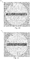
- the embodiment illustrated in Figure 4 has 10 illuminated regions 15, or five pairs a/a', b/b', c/c', d/d', e/e'.
- the optical setup and components of the autofocus system involves five pairs of microlenses 13 and a corresponding AF aperture plate 12.
- the illuminated regions are hexagonal and packed in a honeycomb closest packing. As compared to circular regions, more pixels of the image sensor are used, reducing the need for per-pixel-efficiency of the sensor.
- values of the selected pixels in each region are used to generate a pair of curves of pixel value as a function of pixel position (phase signals). These curves are correlated to identify same shape features and determine relative positions of these.
- curves f and g differing only by an unknown shift along their position (x) axis.
- the cross correlation formula essentially slides the g function along the x-axis, calculating the integral of their product at each position. When the functions match, the value of ( f ⁇ g ) is maximized.
- a calibration target can be held in the centre of the field of view of the camera, preferably on a flat, white background, and brought into focus either by exact knowledge of its distance and the focus state of the camera lens or by a secondary focus system such as contrast focus by the taking sensor.
- the images on the autofocus sensor 14 are shown in Figure 5 , where the calibration target (here an X) is depicted in both illuminated regions as 16 and 17 respectively. Due to non-perfect components and alignment, the illuminated regions and thus the X's are displaced.
- the displacement could be in either or both of the directions parallel to the direction between the regions, here horizontal, x, and orthogonal to thereto, here vertical, y.
- the displacement orthogonal to the direction between the regions is discussed and is also the situation illustrated in Figure 5 where the displacement is y.
- the default corresponding collections zones in the illuminated regions would be lines 18 and 19, respectively. Due to the misalignment, line 19 does not overlap with the centre of the calibration target 17, and a correlation analysis between the curves would give a poor correlation and an imprecise focus adjustment signal.
- the following steps can be carried out to calibrate the autofocus system:
- This offset or displacement is the value required for the calibration and will be referred to as the calibration displacement, and are typically split into a component parallel to a direction between the regions and a component orthogonal to the direction between the regions.
- the calibration displacement can be used to set default collection zones as sets of pixels, which are displaced orthogonally to the direction between the regions by the orthogonal component of the displacement.
- sets of pixels from the regions used in correlation analysis should be orthogonally displaced by this component. In the situation illustrated in Figure 5 , this would mean setting line of pixels 20, displaced y from line 18, as the default collection zone for the right region.
- the calibration displacement parallel to the direction between the regions is also needed. But, since the collection sets in the one-dimensional case, are directed in this direction and often extend through most, or the entirety of, the illuminated regions, it does not affect the selectin of pixels used but is simply a constant added to the correlation result when generating the phase measurement signal.
- the calibration can be carried out by:
- the calibration displacement can be used for selecting a pair of collection zones lying at or close to the centres of the regions (determined in step 1) while having the orthogonal component of the calibration displacement, here y (determined in step 4) as the default to be used when generating the focus measurement signal.
- the orthogonal component can be used whenever selection collection zones, so that zones in the regions are displaced accordingly.
- step 1 If the positions and shape of the regions can be determined with a high precision, in step 1, this would suffice to determine their centres (vertical and horizontal) and their relative displacements, and the default pair of collection zones could be selected intersecting these centres directly.
- the focus profiles are typically not sufficiently defined to determine the displacement as precise as with correlation analysis using a calibration target.
- this procedure involves much more computation - reading entire image to determine region positions and carrying out and scoring many correlation analyses - it allows for a fully automated autofocus calibration procedure that can be carried out anytime by anyone.
- the user would simply place a standard target in front of the camera and initiate the calibration.
- this calibration can be carried out without a standardized calibration target, but any object having significant features that would lead to a precise correlation.
- the instruction could be to draw a black X of about 20 x 20 cm on a white background and place it about one meter in front of the camera.
- the calibration displacement may be determined by determining the positions of the calibration target in both regions by other kinds of analysis (1D or 2D) than correlation analysis.
- the illuminated region is covered multiple columns and rows of small pixels. This renders a number of new functionalities possible where the extraction of the autofocus phase signal can be dynamically optimized for various scene and lightning conditions.
- FIG. 7 illustrates a horizontal line 22 of pixels, each pixel being a subset of three vertically stacked pixels that are combined to collect enough light.
- the small pixels provide a high resolution, but in order to have a large signal to nose ration pixels are typically merged in the lateral direction, which does not affect the sampling rate of the phase signal.
- Figure 8 illustrates a line 23 of pixels directed in an oblique direction of +45°.
- the pixels of the line 23 consist of sets of seven pixels oriented along a -45° direction whose values are merged, corresponding to lateral sections of a +45° oriented line "stacked" in the horizontal direction.
- this collection zone "looks" in the direction of +45°, but is still oriented parallel to the direction between the horizontally displaced regions.
- the phase signals from the sets along different directions are correlated and the pair with the strongest correlation is selected. Having performed the correlation for the selected pair, a focus measurement signal is generated and the lens is moved accordingly. The procedure is iterated until focus is achieved in that there is no displacement between the signals from the selected pair.
- the correlation analysis is performed between values of sets along different directions, the resulting correlations are scored, and one or more sets are selected to be used in generating the focus measurement signal. If more than one set is selected, they might be weighed differently, for example according to the score of their correlations.
- the correlation analysis is first performed between values of a pair of sets along a first direction. If the maximum of the correlation at the best match is not prominent (according to predetermined requirements), then the correlation is poor and another pair of sets along a second direction is selected and correlation analysis is performed. This is repeated along a given number of directions or until a pair with an adequate correlation is found.
- the high-resolution pixels from the 2D image sensor can give a more precise autofocus phase signal than prior art sensors with large pixels, leading to a higher focus precision.
- pixels can be combined to generate larger, digitally generated pixels which collects more light thus giving a more noise free phase signal leading to more robust autofocusing.
- Such effectively larger and thus more light sensitive pixels can also be used if the autofocus speed needs to be faster, requiring shorter exposing time of the autofocus sensor.
- an autofocus procedure utilizing dynamic selection of effective pixel size will be described in relation to Figures 10 and 11 .
- an effective pixel size can be increased by combining adjacent pixels within each illuminated region and performing the correlation analysis between values of the combined pixels.
- the phase signal can still maintain the high resolution in the longitudinal direction, keeping the full precision of the autofocus system.
- Figure 10 pixels are combined with pixels in the rows above and below to generate a line of pixels 25 with nine times larger effective pixel size. If even more light sensitivity is required, then pixels can also be combined in the longitudinal direction, which will keep the robustness of the autofocus but will lack the highest precision.
- Figure 11 pixels are further combined to make a line 26 of 2x9 pixel blocks to generate an eighteen times larger effective pixel size.
- the illuminated regions are images 27 and 28, i.e. two-dimensional signals of pixels values as a function of position in two directions.
- the focus measurement signal can be calculated by determining the displacement, x, of these 2D signals in pair of illuminated regions.
- a 2D cross correlation between the 2D signals can be used to determine the horizontal displacement x between the two 2D signals, which can be used to generate the focus measurement signal.
- 1D cross correlation the maximum value of a 2D cross correlation indicates the location of the best match of the two 2D signals.
- the invention can be implemented by means of hardware, software, firmware or any combination of these.
- the invention or some of the features thereof can also be implemented as software running on one or more data processors and/or digital signal processors.
Landscapes
- Engineering & Computer Science (AREA)
- Multimedia (AREA)
- Signal Processing (AREA)
- Physics & Mathematics (AREA)
- General Physics & Mathematics (AREA)
- Health & Medical Sciences (AREA)
- Biomedical Technology (AREA)
- General Health & Medical Sciences (AREA)
- Optics & Photonics (AREA)
- Focusing (AREA)
- Studio Devices (AREA)
- Automatic Focus Adjustment (AREA)
- Transforming Light Signals Into Electric Signals (AREA)
Priority Applications (3)
| Application Number | Priority Date | Filing Date | Title |
|---|---|---|---|
| EP15169848.7A EP3098638B1 (en) | 2015-05-29 | 2015-05-29 | Adaptive autofocusing system |
| US15/167,492 US10158796B2 (en) | 2015-05-29 | 2016-05-27 | Adaptive autofocusing system |
| JP2016106368A JP2017016103A (ja) | 2015-05-29 | 2016-05-27 | 適応性オートフォーカスシステム |
Applications Claiming Priority (1)
| Application Number | Priority Date | Filing Date | Title |
|---|---|---|---|
| EP15169848.7A EP3098638B1 (en) | 2015-05-29 | 2015-05-29 | Adaptive autofocusing system |
Publications (2)
| Publication Number | Publication Date |
|---|---|
| EP3098638A1 EP3098638A1 (en) | 2016-11-30 |
| EP3098638B1 true EP3098638B1 (en) | 2022-05-11 |
Family
ID=53397798
Family Applications (1)
| Application Number | Title | Priority Date | Filing Date |
|---|---|---|---|
| EP15169848.7A Active EP3098638B1 (en) | 2015-05-29 | 2015-05-29 | Adaptive autofocusing system |
Country Status (3)
| Country | Link |
|---|---|
| US (1) | US10158796B2 (ru) |
| EP (1) | EP3098638B1 (ru) |
| JP (1) | JP2017016103A (ru) |
Families Citing this family (20)
| Publication number | Priority date | Publication date | Assignee | Title |
|---|---|---|---|---|
| US10298834B2 (en) | 2006-12-01 | 2019-05-21 | Google Llc | Video refocusing |
| US10334151B2 (en) * | 2013-04-22 | 2019-06-25 | Google Llc | Phase detection autofocus using subaperture images |
| US10540818B2 (en) | 2015-04-15 | 2020-01-21 | Google Llc | Stereo image generation and interactive playback |
| US10469873B2 (en) | 2015-04-15 | 2019-11-05 | Google Llc | Encoding and decoding virtual reality video |
| US10546424B2 (en) | 2015-04-15 | 2020-01-28 | Google Llc | Layered content delivery for virtual and augmented reality experiences |
| US10341632B2 (en) | 2015-04-15 | 2019-07-02 | Google Llc. | Spatial random access enabled video system with a three-dimensional viewing volume |
| US10444931B2 (en) | 2017-05-09 | 2019-10-15 | Google Llc | Vantage generation and interactive playback |
| US10567464B2 (en) | 2015-04-15 | 2020-02-18 | Google Llc | Video compression with adaptive view-dependent lighting removal |
| US10419737B2 (en) | 2015-04-15 | 2019-09-17 | Google Llc | Data structures and delivery methods for expediting virtual reality playback |
| US10148864B2 (en) * | 2015-07-02 | 2018-12-04 | Pixart Imaging Inc. | Imaging device having phase detection pixels and regular pixels, and operating method thereof |
| JP6700973B2 (ja) * | 2016-05-24 | 2020-05-27 | キヤノン株式会社 | 撮像装置およびその制御方法 |
| US10897566B2 (en) * | 2016-09-28 | 2021-01-19 | Kla-Tencor Corporation | Direct focusing with image binning in metrology tools |
| US10679361B2 (en) | 2016-12-05 | 2020-06-09 | Google Llc | Multi-view rotoscope contour propagation |
| EP3430798B1 (en) * | 2017-03-13 | 2019-06-19 | Lumileds Holding B.V. | Imaging device with an improved autofocusing performance |
| US10594945B2 (en) | 2017-04-03 | 2020-03-17 | Google Llc | Generating dolly zoom effect using light field image data |
| US10474227B2 (en) | 2017-05-09 | 2019-11-12 | Google Llc | Generation of virtual reality with 6 degrees of freedom from limited viewer data |
| US10354399B2 (en) | 2017-05-25 | 2019-07-16 | Google Llc | Multi-view back-projection to a light-field |
| US20190033555A1 (en) * | 2017-07-28 | 2019-01-31 | Qualcomm Incorporated | Phase detection autofocus with diagonal line detection |
| US10965862B2 (en) | 2018-01-18 | 2021-03-30 | Google Llc | Multi-camera navigation interface |
| CN113660425B (zh) * | 2021-08-19 | 2023-08-22 | 维沃移动通信(杭州)有限公司 | 图像处理方法、装置、电子设备及可读存储介质 |
Citations (2)
| Publication number | Priority date | Publication date | Assignee | Title |
|---|---|---|---|---|
| US6297909B1 (en) * | 1998-12-09 | 2001-10-02 | Asahi Kogaku Kogyo Kabushiki Kaisha | Focus detecting optical system |
| EP2938062A1 (en) * | 2014-04-25 | 2015-10-28 | Canon Kabushiki Kaisha | Image capturing apparatus and method for controlling image capturing apparatus |
Family Cites Families (25)
| Publication number | Priority date | Publication date | Assignee | Title |
|---|---|---|---|---|
| US6577344B2 (en) | 1996-09-27 | 2003-06-10 | Canon Kabushiki Kaisha | Focus state detection apparatus with image sensing device controls |
| US6088537A (en) | 1997-04-15 | 2000-07-11 | Canon Kabushiki Kaisha | Focus detecting device |
| JP4384288B2 (ja) | 1999-05-27 | 2009-12-16 | オリンパス株式会社 | 焦点検出装置 |
| JP5264131B2 (ja) * | 2007-09-14 | 2013-08-14 | キヤノン株式会社 | 撮像装置 |
| US8680451B2 (en) | 2007-10-02 | 2014-03-25 | Nikon Corporation | Light receiving device, focus detection device and imaging device |
| JP5317562B2 (ja) * | 2008-07-17 | 2013-10-16 | キヤノン株式会社 | 位相差検出装置、撮像装置、位相差検出方法、位相差検出プログラム |
| JP5276374B2 (ja) * | 2008-07-25 | 2013-08-28 | キヤノン株式会社 | 焦点検出装置 |
| JP5097077B2 (ja) * | 2008-10-10 | 2012-12-12 | キヤノン株式会社 | 撮像装置及びその制御方法及びプログラム |
| JP2010113272A (ja) * | 2008-11-10 | 2010-05-20 | Panasonic Corp | 撮像装置 |
| JP5455397B2 (ja) * | 2009-03-02 | 2014-03-26 | キヤノン株式会社 | 光学機器 |
| JP5578984B2 (ja) * | 2009-12-03 | 2014-08-27 | キヤノン株式会社 | 光電変換装置、焦点検出装置及び撮像システム |
| JP2012137600A (ja) * | 2010-12-27 | 2012-07-19 | Sony Corp | 撮像システム、撮像装置、およびプログラム |
| JP5744545B2 (ja) * | 2011-01-31 | 2015-07-08 | キヤノン株式会社 | 固体撮像装置およびカメラ |
| US8508652B2 (en) * | 2011-02-03 | 2013-08-13 | DigitalOptics Corporation Europe Limited | Autofocus method |
| JP5868056B2 (ja) * | 2011-07-27 | 2016-02-24 | キヤノン株式会社 | 光電変換装置、焦点検出装置及び撮像システム |
| JP2013054288A (ja) * | 2011-09-06 | 2013-03-21 | Nikon Corp | 焦点検出装置、撮像装置 |
| JP2013171178A (ja) * | 2012-02-21 | 2013-09-02 | Sony Corp | オートフォーカス装置、オートフォーカス制御方法、及び、撮像装置 |
| JP5750550B2 (ja) * | 2012-09-06 | 2015-07-22 | 富士フイルム株式会社 | 撮像装置及び合焦制御方法 |
| CN104641275B (zh) * | 2012-09-11 | 2017-12-12 | 索尼公司 | 成像控制装置、成像设备和成像控制装置执行的控制方法 |
| JP6249636B2 (ja) * | 2013-05-28 | 2017-12-20 | キヤノン株式会社 | 撮像装置およびその制御方法 |
| US9473688B2 (en) * | 2012-12-20 | 2016-10-18 | Canon Kabushiki Kaisha | Image pickup apparatus comprising a plurality of imaging sensors and image processing units |
| JP6108884B2 (ja) * | 2013-03-08 | 2017-04-05 | キヤノン株式会社 | 光電変換装置及び撮像システム |
| JP6317548B2 (ja) * | 2013-04-10 | 2018-04-25 | キヤノン株式会社 | 撮像装置及びその制御方法 |
| JP5705270B2 (ja) * | 2013-05-27 | 2015-04-22 | キヤノン株式会社 | 撮像装置、撮像システム、撮像装置の制御方法、プログラム、および、記憶媒体 |
| JP2015102735A (ja) * | 2013-11-26 | 2015-06-04 | 株式会社ニコン | 焦点検出装置および撮像装置 |
-
2015
- 2015-05-29 EP EP15169848.7A patent/EP3098638B1/en active Active
-
2016
- 2016-05-27 JP JP2016106368A patent/JP2017016103A/ja active Pending
- 2016-05-27 US US15/167,492 patent/US10158796B2/en active Active
Patent Citations (2)
| Publication number | Priority date | Publication date | Assignee | Title |
|---|---|---|---|---|
| US6297909B1 (en) * | 1998-12-09 | 2001-10-02 | Asahi Kogaku Kogyo Kabushiki Kaisha | Focus detecting optical system |
| EP2938062A1 (en) * | 2014-04-25 | 2015-10-28 | Canon Kabushiki Kaisha | Image capturing apparatus and method for controlling image capturing apparatus |
Non-Patent Citations (3)
| Title |
|---|
| ANONYMOUS: "Digital single-lens reflex camera - Wikipedia", 26 March 2021 (2021-03-26), XP055790245, Retrieved from the Internet <URL:https://en.wikipedia.org/wiki/Digital_single-lens_reflex_camera> [retrieved on 20210326] * |
| ANONYMOUS: "EVF for Cameras: What it is, and 10 benefits of having one - Improve Photography", 26 March 2021 (2021-03-26), XP055790244, Retrieved from the Internet <URL:https://improvephotography.com/34885/evf/> [retrieved on 20210326] * |
| ANONYMOUS: "Mirrorless interchangeable-lens camera - Wikipedia", 26 March 2021 (2021-03-26), XP055790246, Retrieved from the Internet <URL:https://en.wikipedia.org/wiki/Mirrorless_interchangeable-lens_camera> [retrieved on 20210326] * |
Also Published As
| Publication number | Publication date |
|---|---|
| US10158796B2 (en) | 2018-12-18 |
| US20160353006A1 (en) | 2016-12-01 |
| JP2017016103A (ja) | 2017-01-19 |
| EP3098638A1 (en) | 2016-11-30 |
Similar Documents
| Publication | Publication Date | Title |
|---|---|---|
| EP3098638B1 (en) | Adaptive autofocusing system | |
| US9204067B2 (en) | Image sensor and image capturing apparatus | |
| CN101960353B (zh) | 焦点检测装置和具有焦点检测装置的成像设备 | |
| JP5489641B2 (ja) | 焦点検出装置及びその制御方法 | |
| JP5097077B2 (ja) | 撮像装置及びその制御方法及びプログラム | |
| CN103837959B (zh) | 焦点检测设备、焦点检测方法及摄像设备 | |
| CN104125394B (zh) | 摄像装置及其控制方法 | |
| JP2007121896A (ja) | 焦点検出装置および光学システム | |
| CN107249097A (zh) | 摄像设备及其控制方法 | |
| JP5211590B2 (ja) | 撮像素子および焦点検出装置 | |
| JP4995002B2 (ja) | 撮像装置、合焦装置、撮像方法および合焦方法 | |
| JP2012141240A (ja) | 測距装置、測距方法および撮像装置、撮像方法 | |
| JP2002191060A (ja) | 3次元撮像装量 | |
| CN1275725A (zh) | 焦点检测装置 | |
| JP7292123B2 (ja) | 撮像装置及びその制御方法、プログラム、記憶媒体 | |
| JP2009151154A (ja) | 受光素子、焦点検出装置および撮像装置 | |
| JP2011022457A (ja) | 焦点検出装置 | |
| JPH09126757A (ja) | 距離測定装置 | |
| JP2000019386A (ja) | カメラ | |
| JP2020113948A (ja) | 撮像素子、撮像装置、及び制御方法、並びにプログラム | |
| WO2020066341A1 (ja) | 合焦度検出装置、深度マップ生成装置、及び、電子機器 | |
| JP5725132B2 (ja) | 焦点検出装置 | |
| JP2023114698A (ja) | 撮像装置、撮像装置の制御方法、およびプログラム | |
| JP5409156B2 (ja) | 焦点検出装置 | |
| JP5725131B2 (ja) | 焦点検出装置 |
Legal Events
| Date | Code | Title | Description |
|---|---|---|---|
| PUAI | Public reference made under article 153(3) epc to a published international application that has entered the european phase |
Free format text: ORIGINAL CODE: 0009012 |
|
| 17P | Request for examination filed |
Effective date: 20160610 |
|
| AK | Designated contracting states |
Kind code of ref document: A1 Designated state(s): AL AT BE BG CH CY CZ DE DK EE ES FI FR GB GR HR HU IE IS IT LI LT LU LV MC MK MT NL NO PL PT RO RS SE SI SK SM TR |
|
| AX | Request for extension of the european patent |
Extension state: BA ME |
|
| STAA | Information on the status of an ep patent application or granted ep patent |
Free format text: STATUS: EXAMINATION IS IN PROGRESS |
|
| 17Q | First examination report despatched |
Effective date: 20200422 |
|
| STAA | Information on the status of an ep patent application or granted ep patent |
Free format text: STATUS: EXAMINATION IS IN PROGRESS |
|
| GRAP | Despatch of communication of intention to grant a patent |
Free format text: ORIGINAL CODE: EPIDOSNIGR1 |
|
| STAA | Information on the status of an ep patent application or granted ep patent |
Free format text: STATUS: GRANT OF PATENT IS INTENDED |
|
| INTG | Intention to grant announced |
Effective date: 20211125 |
|
| GRAS | Grant fee paid |
Free format text: ORIGINAL CODE: EPIDOSNIGR3 |
|
| GRAA | (expected) grant |
Free format text: ORIGINAL CODE: 0009210 |
|
| STAA | Information on the status of an ep patent application or granted ep patent |
Free format text: STATUS: THE PATENT HAS BEEN GRANTED |
|
| AK | Designated contracting states |
Kind code of ref document: B1 Designated state(s): AL AT BE BG CH CY CZ DE DK EE ES FI FR GB GR HR HU IE IS IT LI LT LU LV MC MK MT NL NO PL PT RO RS SE SI SK SM TR |
|
| REG | Reference to a national code |
Ref country code: GB Ref legal event code: FG4D |
|
| REG | Reference to a national code |
Ref country code: CH Ref legal event code: EP |
|
| REG | Reference to a national code |
Ref country code: AT Ref legal event code: REF Ref document number: 1491920 Country of ref document: AT Kind code of ref document: T Effective date: 20220515 |
|
| REG | Reference to a national code |
Ref country code: DE Ref legal event code: R096 Ref document number: 602015078845 Country of ref document: DE |
|
| REG | Reference to a national code |
Ref country code: IE Ref legal event code: FG4D |
|
| REG | Reference to a national code |
Ref country code: LT Ref legal event code: MG9D |
|
| REG | Reference to a national code |
Ref country code: NL Ref legal event code: MP Effective date: 20220511 |
|
| REG | Reference to a national code |
Ref country code: AT Ref legal event code: MK05 Ref document number: 1491920 Country of ref document: AT Kind code of ref document: T Effective date: 20220511 |
|
| PG25 | Lapsed in a contracting state [announced via postgrant information from national office to epo] |
Ref country code: SE Free format text: LAPSE BECAUSE OF FAILURE TO SUBMIT A TRANSLATION OF THE DESCRIPTION OR TO PAY THE FEE WITHIN THE PRESCRIBED TIME-LIMIT Effective date: 20220511 Ref country code: PT Free format text: LAPSE BECAUSE OF FAILURE TO SUBMIT A TRANSLATION OF THE DESCRIPTION OR TO PAY THE FEE WITHIN THE PRESCRIBED TIME-LIMIT Effective date: 20220912 Ref country code: NO Free format text: LAPSE BECAUSE OF FAILURE TO SUBMIT A TRANSLATION OF THE DESCRIPTION OR TO PAY THE FEE WITHIN THE PRESCRIBED TIME-LIMIT Effective date: 20220811 Ref country code: NL Free format text: LAPSE BECAUSE OF FAILURE TO SUBMIT A TRANSLATION OF THE DESCRIPTION OR TO PAY THE FEE WITHIN THE PRESCRIBED TIME-LIMIT Effective date: 20220511 Ref country code: LT Free format text: LAPSE BECAUSE OF FAILURE TO SUBMIT A TRANSLATION OF THE DESCRIPTION OR TO PAY THE FEE WITHIN THE PRESCRIBED TIME-LIMIT Effective date: 20220511 Ref country code: HR Free format text: LAPSE BECAUSE OF FAILURE TO SUBMIT A TRANSLATION OF THE DESCRIPTION OR TO PAY THE FEE WITHIN THE PRESCRIBED TIME-LIMIT Effective date: 20220511 Ref country code: GR Free format text: LAPSE BECAUSE OF FAILURE TO SUBMIT A TRANSLATION OF THE DESCRIPTION OR TO PAY THE FEE WITHIN THE PRESCRIBED TIME-LIMIT Effective date: 20220812 Ref country code: FI Free format text: LAPSE BECAUSE OF FAILURE TO SUBMIT A TRANSLATION OF THE DESCRIPTION OR TO PAY THE FEE WITHIN THE PRESCRIBED TIME-LIMIT Effective date: 20220511 Ref country code: ES Free format text: LAPSE BECAUSE OF FAILURE TO SUBMIT A TRANSLATION OF THE DESCRIPTION OR TO PAY THE FEE WITHIN THE PRESCRIBED TIME-LIMIT Effective date: 20220511 Ref country code: BG Free format text: LAPSE BECAUSE OF FAILURE TO SUBMIT A TRANSLATION OF THE DESCRIPTION OR TO PAY THE FEE WITHIN THE PRESCRIBED TIME-LIMIT Effective date: 20220811 Ref country code: AT Free format text: LAPSE BECAUSE OF FAILURE TO SUBMIT A TRANSLATION OF THE DESCRIPTION OR TO PAY THE FEE WITHIN THE PRESCRIBED TIME-LIMIT Effective date: 20220511 |
|
| PG25 | Lapsed in a contracting state [announced via postgrant information from national office to epo] |
Ref country code: RS Free format text: LAPSE BECAUSE OF FAILURE TO SUBMIT A TRANSLATION OF THE DESCRIPTION OR TO PAY THE FEE WITHIN THE PRESCRIBED TIME-LIMIT Effective date: 20220511 Ref country code: PL Free format text: LAPSE BECAUSE OF FAILURE TO SUBMIT A TRANSLATION OF THE DESCRIPTION OR TO PAY THE FEE WITHIN THE PRESCRIBED TIME-LIMIT Effective date: 20220511 Ref country code: LV Free format text: LAPSE BECAUSE OF FAILURE TO SUBMIT A TRANSLATION OF THE DESCRIPTION OR TO PAY THE FEE WITHIN THE PRESCRIBED TIME-LIMIT Effective date: 20220511 Ref country code: IS Free format text: LAPSE BECAUSE OF FAILURE TO SUBMIT A TRANSLATION OF THE DESCRIPTION OR TO PAY THE FEE WITHIN THE PRESCRIBED TIME-LIMIT Effective date: 20220911 |
|
| REG | Reference to a national code |
Ref country code: CH Ref legal event code: PL |
|
| REG | Reference to a national code |
Ref country code: BE Ref legal event code: MM Effective date: 20220531 |
|
| PG25 | Lapsed in a contracting state [announced via postgrant information from national office to epo] |
Ref country code: SM Free format text: LAPSE BECAUSE OF FAILURE TO SUBMIT A TRANSLATION OF THE DESCRIPTION OR TO PAY THE FEE WITHIN THE PRESCRIBED TIME-LIMIT Effective date: 20220511 Ref country code: SK Free format text: LAPSE BECAUSE OF FAILURE TO SUBMIT A TRANSLATION OF THE DESCRIPTION OR TO PAY THE FEE WITHIN THE PRESCRIBED TIME-LIMIT Effective date: 20220511 Ref country code: RO Free format text: LAPSE BECAUSE OF FAILURE TO SUBMIT A TRANSLATION OF THE DESCRIPTION OR TO PAY THE FEE WITHIN THE PRESCRIBED TIME-LIMIT Effective date: 20220511 Ref country code: LU Free format text: LAPSE BECAUSE OF NON-PAYMENT OF DUE FEES Effective date: 20220529 Ref country code: EE Free format text: LAPSE BECAUSE OF FAILURE TO SUBMIT A TRANSLATION OF THE DESCRIPTION OR TO PAY THE FEE WITHIN THE PRESCRIBED TIME-LIMIT Effective date: 20220511 Ref country code: DK Free format text: LAPSE BECAUSE OF FAILURE TO SUBMIT A TRANSLATION OF THE DESCRIPTION OR TO PAY THE FEE WITHIN THE PRESCRIBED TIME-LIMIT Effective date: 20220511 Ref country code: CZ Free format text: LAPSE BECAUSE OF FAILURE TO SUBMIT A TRANSLATION OF THE DESCRIPTION OR TO PAY THE FEE WITHIN THE PRESCRIBED TIME-LIMIT Effective date: 20220511 Ref country code: CH Free format text: LAPSE BECAUSE OF NON-PAYMENT OF DUE FEES Effective date: 20220531 Ref country code: LI Free format text: LAPSE BECAUSE OF NON-PAYMENT OF DUE FEES Effective date: 20220531 |
|
| REG | Reference to a national code |
Ref country code: DE Ref legal event code: R097 Ref document number: 602015078845 Country of ref document: DE |
|
| PG25 | Lapsed in a contracting state [announced via postgrant information from national office to epo] |
Ref country code: MC Free format text: LAPSE BECAUSE OF FAILURE TO SUBMIT A TRANSLATION OF THE DESCRIPTION OR TO PAY THE FEE WITHIN THE PRESCRIBED TIME-LIMIT Effective date: 20220511 |
|
| PLBE | No opposition filed within time limit |
Free format text: ORIGINAL CODE: 0009261 |
|
| STAA | Information on the status of an ep patent application or granted ep patent |
Free format text: STATUS: NO OPPOSITION FILED WITHIN TIME LIMIT |
|
| PG25 | Lapsed in a contracting state [announced via postgrant information from national office to epo] |
Ref country code: AL Free format text: LAPSE BECAUSE OF FAILURE TO SUBMIT A TRANSLATION OF THE DESCRIPTION OR TO PAY THE FEE WITHIN THE PRESCRIBED TIME-LIMIT Effective date: 20220511 |
|
| 26N | No opposition filed |
Effective date: 20230214 |
|
| PG25 | Lapsed in a contracting state [announced via postgrant information from national office to epo] |
Ref country code: IE Free format text: LAPSE BECAUSE OF NON-PAYMENT OF DUE FEES Effective date: 20220529 |
|
| PG25 | Lapsed in a contracting state [announced via postgrant information from national office to epo] |
Ref country code: SI Free format text: LAPSE BECAUSE OF FAILURE TO SUBMIT A TRANSLATION OF THE DESCRIPTION OR TO PAY THE FEE WITHIN THE PRESCRIBED TIME-LIMIT Effective date: 20220511 Ref country code: BE Free format text: LAPSE BECAUSE OF NON-PAYMENT OF DUE FEES Effective date: 20220531 |
|
| PGFP | Annual fee paid to national office [announced via postgrant information from national office to epo] |
Ref country code: FR Payment date: 20230525 Year of fee payment: 9 Ref country code: DE Payment date: 20230530 Year of fee payment: 9 |
|
| PGFP | Annual fee paid to national office [announced via postgrant information from national office to epo] |
Ref country code: GB Payment date: 20230529 Year of fee payment: 9 |
|
| PG25 | Lapsed in a contracting state [announced via postgrant information from national office to epo] |
Ref country code: IT Free format text: LAPSE BECAUSE OF FAILURE TO SUBMIT A TRANSLATION OF THE DESCRIPTION OR TO PAY THE FEE WITHIN THE PRESCRIBED TIME-LIMIT Effective date: 20220511 |
|
| PG25 | Lapsed in a contracting state [announced via postgrant information from national office to epo] |
Ref country code: HU Free format text: LAPSE BECAUSE OF FAILURE TO SUBMIT A TRANSLATION OF THE DESCRIPTION OR TO PAY THE FEE WITHIN THE PRESCRIBED TIME-LIMIT; INVALID AB INITIO Effective date: 20150529 |
|
| PG25 | Lapsed in a contracting state [announced via postgrant information from national office to epo] |
Ref country code: MK Free format text: LAPSE BECAUSE OF FAILURE TO SUBMIT A TRANSLATION OF THE DESCRIPTION OR TO PAY THE FEE WITHIN THE PRESCRIBED TIME-LIMIT Effective date: 20220511 Ref country code: CY Free format text: LAPSE BECAUSE OF FAILURE TO SUBMIT A TRANSLATION OF THE DESCRIPTION OR TO PAY THE FEE WITHIN THE PRESCRIBED TIME-LIMIT Effective date: 20220511 |