EP3092935B1 - Wasserführendes haushaltsgerät - Google Patents
Wasserführendes haushaltsgerät Download PDFInfo
- Publication number
- EP3092935B1 EP3092935B1 EP16169503.6A EP16169503A EP3092935B1 EP 3092935 B1 EP3092935 B1 EP 3092935B1 EP 16169503 A EP16169503 A EP 16169503A EP 3092935 B1 EP3092935 B1 EP 3092935B1
- Authority
- EP
- European Patent Office
- Prior art keywords
- receiving area
- insulation element
- water
- domestic appliance
- insulation
- Prior art date
- Legal status (The legal status is an assumption and is not a legal conclusion. Google has not performed a legal analysis and makes no representation as to the accuracy of the status listed.)
- Active
Links
Images


Classifications
-
- A—HUMAN NECESSITIES
- A47—FURNITURE; DOMESTIC ARTICLES OR APPLIANCES; COFFEE MILLS; SPICE MILLS; SUCTION CLEANERS IN GENERAL
- A47L—DOMESTIC WASHING OR CLEANING; SUCTION CLEANERS IN GENERAL
- A47L15/00—Washing or rinsing machines for crockery or tableware
- A47L15/42—Details
- A47L15/4209—Insulation arrangements, e.g. for sound damping or heat insulation
-
- A—HUMAN NECESSITIES
- A47—FURNITURE; DOMESTIC ARTICLES OR APPLIANCES; COFFEE MILLS; SPICE MILLS; SUCTION CLEANERS IN GENERAL
- A47L—DOMESTIC WASHING OR CLEANING; SUCTION CLEANERS IN GENERAL
- A47L15/00—Washing or rinsing machines for crockery or tableware
- A47L15/42—Details
- A47L15/4246—Details of the tub
Definitions
- the present invention relates to a water-conducting household appliance having a receiving area and an arrangement for acoustic and thermal insulation of the receiving area of the water-conducting household appliance.
- the water-conducting household appliance is in particular a dishwasher.
- the receiving area is in particular a washing container of the dishwasher.
- bitumen mats For the acoustic insulation of a washing container of a dishwasher, it is known to apply bitumen mats to the washing container.
- the bitumen mats can be glued to the outside of the washing container, for example with the aid of a hot melt adhesive. Such bitumen mats have a high heat capacity and direct the heat absorbed by the washing away.
- the publication DE 20 2012 103 799 U1 discloses a sound-absorbing sandwich panel that can be used to demolish a dishwasher.
- the sandwich panel has a first layer for sound insulation and a second layer for Entdröhnung and / or thermal insulation.
- the sound-absorbing sandwich panel is produced as a prefabricated component and can be glued, for example, to a washing container of a dishwasher.
- the publication US 2011/0168217 A1 discloses a home appliance comprising a housing having a top plate and a bottom plate opposite each other are arranged and which have a plurality of walls which are connected to the upper plate and the bottom plate, wherein the upper plate, the bottom plate and the plurality of walls having a working space and wherein the housing has an outermost surface.
- the household appliance further comprises a polyurethane foam comprising the reaction product of an isocyanate composition and a resin composition comprising at least one polyol and disposed around at least a portion of the outermost surface of the housing.
- the polyurethane foam has a density of from 20 to 50 pounds per cubic foot ( determined according to ASTM D 1622), a damping factor of at least 0.2 (measured at a temperature of 40 to 60 ° C (determined according to ASTM D 4065) and a K-factor of less than 2.0 btu-in / hr-ft 2 ° F (determined according to ASTM C 518).
- the publication EP 2 359 737 A2 discloses an electrically operated domestic appliance, in particular a dishwasher, a washing machine, a tumble dryer or the like, with one or more inner walls and with one or more outer walls arranged in front of these, wherein between a respective inner wall and an outer wall lying in front of a gap is provided. At least in one intermediate space, there is at least one bridging between the respective inner wall and the outer wall arranged in front of it by an inserted, provided with at least one elastically deformable foam layer stiffening body and / or at least one bridging between the respective inner and outer wall by an introduced, with at least provided a rubber elastic deformable layer provided stiffening body.
- the stiffening body can be a sound-absorbing Entdröhnungsêt in double function.
- the foam or rubber-elastic layer with the outside of the inner wall connected directly or indirectly, in particular glued be.
- the publication DE 10 2011 085 175 A1 discloses a household appliance, in particular a domestic dishwasher, with a component having at least one component wall, in particular made of plastic. At least one side of the component wall is provided with a base layer of a butyl material, in particular butyl adhesive.
- an object of the present invention is to provide a water-conducting household appliance with a receiving area and an improved Arrangement for acoustic and thermal insulation of the receiving area of the water-bearing household appliance to provide.
- a water-conducting household appliance having a receiving area and an arrangement for acoustic and thermal insulation of the receiving area of the water-conducting household appliance, in particular a washing container of a dishwasher, proposed.
- the assembly includes a first insulation member configured to thermally insulate the receiving area and a second insulation member configured to acoustically isolate the receiving area, wherein the first insulation member is disposed between the receiving area and the second insulation member, and wherein first insulation element is foamed directly to the receiving area.
- the first insulation element has both a specific thermal conductivity of less than 0.1 W / (m * K), preferably less than 0.05 W / (m * K), as well as a mass density or density between 5 and 90 kg / m 3 on.
- the fact that the first insulating element is foamed directly to the receiving area, can be dispensed with a subsequent attachment of the arrangement to the receiving area.
- a cost reduction in the production of a water-conducting household appliance can be achieved with such an arrangement.
- the assembly complexity can be reduced, since an additional step of isolating the receiving area is dispensable.
- the assembly may be attached thereto during manufacture of the receiving area.
- the receiving area preferably has a wall with two opposite side walls, a ceiling, a floor arranged opposite the ceiling and a rear wall arranged opposite a door of the receiving area.
- the arrangement may be provided on the entire wall and on the door.
- the arrangement may comprise the wall or a part of the wall.
- the arrangement may be provided, for example, only on the side walls, on the rear wall and on the ceiling.
- the receiving area is completely foamed with the first insulating element.
- the arrangement is provided on the outside on the receiving area.
- a specific heat capacity of the first insulating member is as small as possible and smaller than 1,400 J / (kg * K).
- chemical additives may be added to the material of the first insulating element and / or the surface of the receiving area may be pretreated, for example roughened, so that the first insulating element is in particular permanently connected to the receiving area.
- the first insulation element in particular represents a rigid connection between the receiving region and the second insulation element. That is to say, the first insulation element can transmit vibrations of the reception region, in particular lossless or at least low-loss, to the second insulation element.
- the mass density or density of the second insulating member is preferably larger than 1,000 kg / m 3 .
- the first insulation element is configured to transmit vibrations from the receiving region to the second insulation element.
- the second insulation element has a higher density than the first insulation element.
- the first insulation element prevents heat transfer from the receiving region to the second insulation element.
- the second insulation element is preferably configured to convert vibrations into heat.
- the first insulation element is made of a foamed plastic material, in particular of a foamed polyurethane material.
- the first insulating element is made of a closed-cell plastic material.
- the first insulating element may be made of a polystyrene foam, for example.
- the second insulation element is made of a bitumen material, in particular of a metal- and / or rock-filled bitumen material, or of a plastic material, in particular of a metal- and / or rock-filled plastic material.
- the bitumen material or the plastic material may comprise finely divided metal powder or rock flour.
- the second insulating element is preferably plate-shaped or mat-shaped.
- the second insulation element may also be made of a butyl material.
- the second insulating element may be a metal plate, in particular a steel plate.
- the first insulation element has a thickness of 5 to 50 mm, preferably 10 to 45 mm, more preferably 15 to 40 mm.
- the thickness of the first insulating element is less than 50 mm.
- the minimum thickness of the first insulating element is preferably 5 mm.
- a thickness of the second insulating member is smaller than the thickness of the first insulating member.
- the thickness of the first insulation element is a multiple of the thickness of the second insulation element.
- the second insulation element may, for example, have a thickness of 1 to 5 mm.
- the second insulating element at a temperature of 20 ° C, a loss factor of greater than 0.08, preferably greater than 0.15, on. As a result, a good Entdröhnung the receiving area or a damping of the vibrations of the receiving area is achieved.
- a cover element in particular a paper sheet, a metal foil or a metal plate, is arranged on the outside of the second insulation element on the outside.
- the cover has a very low emission coefficient.
- the emission coefficient of the cover is less than 0.5, preferably less than 0.1.
- aluminum foil is used as the material for the cover element.
- a mass element in particular a metal plate, is arranged between the first insulation element and the second insulation element.
- the metal plate may be covered with the cover. Alternatively, can be dispensed with the cover. Instead of a steel sheet may be used for the mass element, a damping coating with high mass density or density.
- the density of this material is preferably greater than 1,800 kg / m 3 , preferably greater than 2,200 kg / m 3 .
- a cover element with a low emission coefficient can also be provided here.
- a heat exchanger is arranged in the first insulation element.
- the heat exchanger is foamed with material of the first insulating element.
- the heat exchanger may be, for example, a capillary tube heat exchanger, a copper tube heat exchanger, a plate heat exchanger, or the like.
- the heat exchanger is arranged at least on side walls, preferably also on the rear wall and optionally on the ceiling of the receiving area. The rigid connection between the receiving area and the second insulating element is retained.
- the distance between tubes of the heat exchanger is dimensioned sufficiently large.
- the distance between outer sides of the tubes is at least the diameter of the individual tubes.
- the tubes of the same can be mounted vertically or at least obliquely with sufficient slope at the receiving portion.
- the heat exchanger is in touching contact with the receiving area.
- the heat exchanger may be in linear contact with the receiving area.
- the tubes of the heat exchanger for example, have a rectangular geometry, whereby a larger contact surface is achieved with the receiving area.
- a material with good thermal conductivity can be used.
- the thermal paste has a specific thermal conductivity of 0.5 W / (m * K) or greater.
- the thermal compound is preferably applied to the receiving area only in the region of the heat exchanger.
- a separation of the adhesive connection between the first insulation element and the second insulation element or the mass element is acoustically advantageous.
- the separation can be done by using a release layer such as a wax layer or the like or a polyethylene film.
- the separating layer preferably has a surface free energy of greater than 25 mN / m, preferably greater than 35 mN / m.
- connection of the first insulating element to the receiving area can take place adhesively; but this is not a mandatory requirement. In any case, care should be taken that the space between the receiving area and the second insulating element is largely filled with the first insulating element, so that a force transmission perpendicular to the surface is possible. This is possible with complete filling without adhesive connection. This achieves a reduction of the radiated sound power. This power transmission can also take place when the first insulating element rests only partially on the receiving area or the second insulating element.
- connection between the second insulating member and the cover should be adhesive; but this is not a mandatory requirement.
- the use of viscoelastic polyurethane foam may also be acoustically advantageous. As a result, acoustic vibrations can already be damped in the first insulating element.
- the loss factor of the first insulating element should thus be greater than 0.01, preferably greater than 0.1.
- a receiving area for a water-conducting household appliance, in particular a washing container for a dishwasher proposed with such an arrangement.
- the washing container is preferably made of a steel sheet.
- the water-bearing household appliance can also be a washing machine. Alternatively, the arrangement can also be used in other water-conducting household appliances.
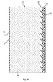
- the Fig. 1 shows a schematic perspective view of a, in particular water-bearing, household appliance 1.
- the household appliance 1 may for example be a dishwasher, a washing machine, a refrigerator or the like.
- a dishwasher is shown.
- the household appliance 1 has a receiving area 2, which is closed by a door 3, in particular watertight.
- a sealing device can be provided between the door 3 and the receiving area 2.
- the receiving area 2, a washing container in the Fig. 1 be shown dishwasher.
- the receiving area 2 is preferably cuboidal.
- the receiving area 2 can be made of a sheet steel.
- the receiving area 2 can be made of a plastic material at least in sections.
- the receiving area 2 and the door 3 can form a rinsing chamber 4 for rinsing dishes.
- the receiving area 2 can be arranged in the interior of a housing of the household appliance 1.
- the door 3 is in the Fig. 1 shown in their open position. By pivoting about a provided at a lower end of the door 3 pivot axis 5, the door 3 can be closed or opened.
- the receiving area 2 has a wall 6 with a bottom 7, a ceiling 7 arranged opposite the floor 7, a door 3 arranged opposite the rear wall 9 and two side walls 10, 11 arranged opposite one another.
- the bottom 7, the ceiling 8, the rear wall 9 and the side walls 10, 11 may for example be made of a stainless steel sheet.
- the bottom 7 may be made of a plastic material.
- the household appliance 1 furthermore has at least one washware receptacle 12.
- a plurality of Spülgutagen 12 may be provided, each one of the multiple Spülgutagen 12 is a lower basket, an upper basket or a cutlery drawer of the household appliance 1.
- the plurality of Spülgutagen 12 are preferably arranged one above the other in the receiving area 2.
- Each Spülgutage 12 is optionally in the receiving area 2 into or out of this displaced.
- each Spülgutage 12 in an insertion direction E (arrow) hineinschiebbar in the receiving area 2 and opposite to the insertion direction E (arrow) in a pull-out direction A (arrow) from the receiving area 2 can be pulled out.
- the Fig. 2A 1 shows a schematic sectional view of the side wall 11.
- the household appliance 1 comprises an arrangement 13 for the acoustic and thermal insulation of the receiving area 2 of the household appliance 1.
- the arrangement 13 has a first insulating element 14 which is designed to thermally insulate the receiving area 2.
- the first insulation element 14 is preferably made of a foamed plastic material, in particular of a foamed polyurethane material.
- the first insulating element 14 may be made of a foamed polystyrene material, for example.
- the first Isolation element 14 a closed-pore structure.
- the first insulation element 14 is provided on the outside of the side wall 11. In this case, the outside is to be understood as meaning that the first insulation element 14 points away from the flushing chamber 4.
- the first insulation element 14 is arranged on an outer surface 15 of the side wall 11.
- the first insulation element 14 has a thickness d 14 of preferably 5 to 50 mm, more preferably 10 to 45 mm, more preferably 15 to 40 mm, further preferably 20 to 35 mm, more preferably 25 to 30 mm.
- a density ⁇ 14 of the first insulating member 14 is between 5 and 90 kg / m 3 .
- a specific thermal conductivity ⁇ 14 of the first insulation element 14 is preferably less than 0.1 W / (m * K), preferably less than 0.05 W / (m * K).
- the first insulating element 14 further preferably has a specific heat capacity c 14 of less than 1,400 J / (kg * K).
- the arrangement 13 may be provided on the entire wall 6 of the receiving area 2.
- the arrangement 13 may be provided on the side walls 10, 11, the rear wall 9, the ceiling 8 and the bottom 7.
- the arrangement 13 may also be provided on the door 3.
- the arrangement 13 may also be provided only on the side walls 10, 11 and for example on the rear wall 9 and / or the ceiling 8. In the following, reference will be made only to the side wall 11 for the sake of simplicity.
- the first insulation element 14 is foamed directly onto the receiving region 2, in particular directly to the wall 6.
- chemical additives can be added to the material of the first insulation element 14, which prevent the first insulation element 14 from being detached from the wall 6.
- the outer surface 15 of the side wall 11 can be pretreated alternatively or additionally, for example, roughened, so that the connection between the side wall 11 and the first insulating member 14 does not dissolve.
- the arrangement 13 furthermore has a second insulation element 16.
- the second insulation element 16 is arranged on the first insulation element 14, so that the first insulation element 14 is arranged between the reception region 2 and the second insulation element 16.
- the first insulation element 14 can be foamed onto the receiving region 2 and then the second insulation element 16 can be attached to the first insulation element 14.
- the first insulating element 14 between the receiving area 2 and the second insulating member 16 are foamed directly.
- the first insulation element 14 is preferably connected directly to the second insulation element 16.
- the material of the first insulating element 14, as explained above, appropriate chemical additives are added, which ensure a reliable and permanent connection with the second insulating member 16.
- a thickness d 16 of the second insulating element 16 is preferably smaller than the thickness d 14 of the first insulating element 14.
- the thickness d 16 may be 1 to 10 mm, preferably 1 to 8 mm, more preferably 1 to 5 mm, further preferably 1 to 3 mm, amount.
- the first insulating element 14 effects a rigid connection of the second insulating element 16 to the receiving region 2.
- the first insulating element 14 is configured to transmit vibrations from the receiving region 2 to the second insulating element 16.
- the first insulation element 14 is preferably not adapted to dampen vibrations.
- the first insulating element 14 prevents heat transfer from the receiving area 2 to the second insulating element 16.
- the second insulating element 16 can not extract heat from the receiving area 2.
- the energy efficiency of the household appliance 1 is improved.
- vibrations of the receiving region 2 are converted into heat.
- the second insulation element 16 preferably has a significantly higher density than the first insulation element 14.
- the second insulation element 16 is preferably made of a bitumen material, in particular of a metal- and / or rock-filled bitumen material, or of a plastic material, in particular of a metal- and / or rock-filled plastic material.
- the second insulating element 16 may be made of a butyl material.
- the second insulation element 16 is in particular plate-shaped or mat-shaped.
- the second insulating element 16 may also be a metal sheet, in particular a steel sheet.
- the second insulating element 16 serves to Entdröhnung the receiving area 2 and the damping of vibrations of the receiving area 2.
- the second insulating element 16 preferably has the highest possible loss factor.
- a loss factor in the present case is to be understood as meaning the ratio of the lossy real part to the lossless imaginary part of a complex variable.
- the loss factor of the material of the second insulating element 16 is greater than 0.08, preferably greater than 0.15 at 20 ° C.
- a density ⁇ 16 of the second insulating member 16 is preferably larger than 1,000 kg / m 3 .
- the arrangement 13 further comprises in the Fig. 2A Shown cover 18, which is disposed on the outside of the second insulating member 16.
- the cover 16 is provided on one of the surface 17 of the second insulating member 16 opposite arranged surface 19 of the second insulating member 16.
- the cover member 18 may be a paper sheet, a metal foil such as an aluminum foil, or a thin metal plate.
- the material of the cover member 18 preferably has a low emission coefficient or emissivity.
- the emissivity of a body indicates how much radiation it emits Comparison to an ideal heat radiator, a black body, gives off.
- the cover element 18 preferably has an emission coefficient of less than 0.5, preferably less than 0.1. As a result, the energy loss can be further reduced.
- the Fig. 2B shows a schematic sectional view of an extended embodiment of an arrangement for the isolation of a receiving area 2 of the water-conducting household appliance 1 according to Fig. 2A so on the description of the Fig. 2A referred and also referred to.
- a release layer 27 such as a wax layer or the like or a polyethylene film is disposed between the first insulating member 14 and the second insulating member 16.
- the separating layer 27 preferably has a surface free energy of greater than 25 mN / m, preferably greater than 35 mN / m.
- the Fig. 3A shows a further embodiment of an arrangement 13 for insulating the receiving area 2 of the household appliance 1.
- the embodiment of the arrangement 13 according to the Fig. 3A differs from the embodiment of the arrangement 13 according to the Fig. 2A in that the cover element 18 is not designed as an aluminum foil but as a metal sheet, in particular as a sheet steel.
- a high density damping lining can also be used.
- the density of the material of the damping lining is preferably greater than 1,800 kg / m 3 , preferably greater than 2,200 kg / m 3 .
- the steel sheet can be additionally covered with an aluminum foil.
- the Fig. 3B shows a schematic sectional view of an extended embodiment of an arrangement for the isolation of a receiving area 2 of the water-conducting household appliance 1 according to Fig. 3A so on the description of the Fig. 3A referred and also referred to.
- a release layer 27 such as a wax layer or the like or a polyethylene film is disposed between the first insulating member 14 and the second insulating member 16.
- the separating layer 27 preferably has a surface free energy of greater than 25 mN / m, preferably greater than 35 mN / m.
- the Fig. 4A shows a further embodiment of an arrangement 13 for the isolation of the receiving area 2 of the household appliance 1.
- the arrangement 13 according to the Fig. 4A differs from the arrangement 13 according to the Fig. 2A in that a mass element 20 is arranged between the first insulation element 14 and the second insulation element 16.
- the mass element 20 is preferably a metal plate, in particular a steel plate. Due to the rigid connection of the Receiving portion 2 with the mass element 20 by means of the first insulating member 14, the mass of the mass member 20 on the outside of the receiving portion 2 is acoustically effective. By the covering of the mass element 20 with the second insulating element 16, the acoustic efficiency can be further improved.
- the Fig. 4B shows a schematic sectional view of an extended embodiment of an arrangement for the isolation of a receiving area 2 of the water-conducting household appliance 1 according to Fig. 4A so on the description of the Fig. 4A referred and also referred to.
- a release layer 27 such as a wax layer or the like or a polyethylene film is arranged between the first insulating member 14 and the mass member 20, a release layer 27, such as a wax layer or the like or a polyethylene film is arranged.
- the separating layer 27 preferably has a surface free energy of greater than 25 mN / m, preferably greater than 35 mN / m.
- the Fig. 5A shows a further embodiment of an arrangement 13 for insulating the receiving area 2 of the household appliance 1.
- the embodiment of the arrangement 13 according to the Fig. 5A is a development of the embodiment of the arrangement 13 according to the Fig. 2A
- the arrangement 13 according to the Fig. 5A has a heat exchanger 21 provided in the first insulating element 14.
- the heat exchanger 21 or tubes 22 to 25 of the heat exchanger 21 are in touching contact with the side wall 11.
- the tubes 22 to 25 may be in linear contact with the side wall 11.
- the tubes 22 to 25 may be thermally coupled to the sidewall 11 by means of a thermal grease 26.
- a wall temperature of the receiving area 2 is controllable.
- the heat exchanger 21 may be formed, for example, as a capillary tube heat exchanger, copper tube heat exchanger, plate heat exchanger or the like.
- the heat exchanger 21 is provided on at least one side wall 10, 11, preferably on both side walls 10, 11, on the rear wall 9 and optionally on the ceiling 8 of the receiving area 2.
- the heat exchanger 21 is preferably provided on vertical surfaces of the receiving area 2.
- a distance a 21 between two tubes 22 to 25 of the heat exchanger 21 is selected so that a sufficient contact of the first insulating member 14 is ensured with the receiving area 2.
- the distance a 21 preferably corresponds to at least one diameter d 21 of the individual tubes 22 to 25. In the case of a tube diameter d 21 of less than 10 mm or less than 5 mm, this corresponds to a distance a 21 of at least 10 mm or at least 5 mm.
- the thermal compound 26 adapts well to the contour of the heat exchanger 21 and to the surface of the receiving area 2. As a result, a good heat transfer is guaranteed.
- the thermal grease 26 has a specific thermal conductivity ⁇ 26 of 0.5 W / (m * K) or more.
- the thermal compound 26 is applied to the receiving area 2 only in the area of the heat exchanger 21.
- the geometry of the heat exchanger 21 can be structurally adapted to the surface of the side wall 11.
- the tubes 22 to 25 may be rectangular or semicircular. In order to allow a complete emptying of the heat exchanger 21, the tubes 22 to 25 can be mounted vertically or at least obliquely with sufficient slope.
- the Fig. 5B shows a schematic sectional view of an extended embodiment of an arrangement for the isolation of a receiving area 2 of the water-conducting household appliance 1 according to Fig. 5A so on the description of the Fig. 5A referred and also referred to.
- a release layer 27 such as a wax layer or the like or a polyethylene film is disposed between the first insulating member 14 and the second insulating member 16.
- the separating layer 27 preferably has a surface free energy of greater than 25 mN / m, preferably greater than 35 mN / m.
- the Fig. 6A shows a further embodiment of an arrangement 13.
- the arrangement 13 according to the Fig. 6A is a development of the arrangement 13 according to the Fig. 3A ,
- the arrangement 13 according to the Fig. 6A differs from the arrangement 13 according to the Fig. 3A only by an additional heat exchanger 21st
- the Fig. 6B shows a schematic sectional view of an extended embodiment of an arrangement for the isolation of a receiving area 2 of the water-conducting household appliance 1 according to Fig. 6A so on the description of the Fig. 6A referred and also referred to.
- a release layer 27 such as a wax layer or the like or a polyethylene film is disposed between the first insulating member 14 and the second insulating member 16.
- the separating layer 27 preferably has a surface free energy of greater than 25 mN / m, preferably greater than 35 mN / m.
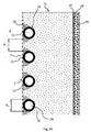
- the Fig. 7A shows a further embodiment of an arrangement 13.
- the arrangement 13 according to the Fig. 7A is a development of the arrangement 13 according to the Fig. 4A ,
- the arrangement 13 according to the Fig. 7A differs from the arrangement 13 according to the Fig. 4A only by an additional heat exchanger 21st
- the Fig. 7B shows a schematic sectional view of an extended embodiment of an arrangement for the isolation of a receiving area 2 of the water-conducting household appliance 1 according to Fig. 7A so on the description of the Fig. 7A referred and also referred to.
- a release layer 27 such as a wax layer or the like or a polyethylene film is arranged between the first insulating member 14 and the mass member 20, a release layer 27, such as a wax layer or the like or a polyethylene film is arranged.
- the separating layer 27 preferably has a surface free energy of greater than 25 mN / m, preferably greater than 35 mN / m.
- the Fig. 8 schematically shows a method for producing the water-conducting household appliance 1.
- the method comprises a step S1 of providing the receiving area 2 of the household appliance 1.
- the receiving area 2 is for example a washing container of a dishwasher. Before the step S1, the receiving area 2 can be made, for example, from a steel sheet.
- the first insulation element 14 is foamed directly onto the receiving region 2, wherein the first insulation element 14 is adapted to thermally isolate the receiving region 2.
- the second insulating element 16 is arranged on the receiving area 2, so that the first insulating element 14 between the receiving area 2 and the second Insulation element 16 is arranged, wherein the second insulating element 16 is adapted to isolate the receiving area 2 acoustically.
- the second insulation element 16 can be placed on the first insulation element 14, for example, as a mat or plate.
- the first insulating element 14 can be foamed between the receiving area 2 and the second insulating element 16, so that the first insulating element 14 is connected directly to the receiving area 2 and the second insulating element 16.
- the arrangement of the second insulation element 16 on the receiving region 2 can be carried out before or after the foaming of the first insulation element 14.
- the thermal insulation of the receiving area 2 by means of the first insulating element 14 prevents heat transfer into the acoustically active materials, that is to say into the second insulating element 16 and into the optional ground element 20, over the entire rinsing cycle.
- the second insulating element 16 and the grounding element 20 can thus open the temperature level of the environment are kept. As a result, little or no energy needs to be expended to heat them up.
- the use of an efficient heat exchanger 21 further ensures a good and reproducible drying result.
Landscapes
- Heat-Pump Type And Storage Water Heaters (AREA)
- Main Body Construction Of Washing Machines And Laundry Dryers (AREA)
- Domestic Plumbing Installations (AREA)
- Detail Structures Of Washing Machines And Dryers (AREA)
Description
- Die vorliegende Erfindung betrifft ein wasserführendes Haushaltsgerät mit einem Aufnahmebereich und einer Anordnung zur akustischen und thermischen Isolation des Aufnahmebereichs des wasserführenden Haushaltsgeräts. Das wasserführende Haushaltsgerät ist insbesondere eine Geschirrspülmaschine. Der Aufnahmebereich ist insbesondere ein Spülbehälter der Geschirrspülmaschine.
Zur akustischen Isolation eines Spülbehälters einer Geschirrspülmaschine ist es bekannt, auf den Spülbehälter Bitumenmatten aufzubringen. Die Bitumenmatten können beispielsweise mit Hilfe eines Schmelzklebers außenseitig auf den Spülbehälter aufgeklebt werden. Derartige Bitumenmatten haben ein hohes Wärmeaufnahmevermögen und leiten die aufgenommene Wärme von dem Spülbehälter weg. Wird der Anteil der mit den Bitumenmatten belegten Fläche des Spülbehälters reduziert, lässt sich die Energieaufnahme der Geschirrspülmaschine reduzieren. Diese Reduktion der belegten Fläche hat jedoch zur Folge, dass die Schallemission der Geschirrspülmaschine ansteigt.
Die DruckschriftDE 20 2012 103 799 U1 offenbart eine schalldämpfende Sandwichplatte, die zum Entdröhnen einer Geschirrspülmaschine eingesetzt werden kann. Die Sandwichplatte weist eine erste Schicht zur Schalldämmung und eine zweite Schicht zur Entdröhnung und/oder thermischen Isolierung auf. Die schalldämpfende Sandwichplatte wird als vorgefertigtes Bauteil hergestellt und kann beispielsweise auf einen Spülbehälter einer Geschirrspülmaschine aufgeklebt werden.
Die DruckschriftUS 2011/0168217 A1 offenbart ein Haushaltsgerät umfassend ein Gehäuse mit einer oberen Platte und einer Bodenplatte, die einander gegenüberliegend angeordnet sind und die eine Vielzahl von Wänden aufweisen, welche mit der oberen Platte und der Bodenplatte verbunden sind, wobei die obere Platte, die Bodenplatte und die Vielzahl von Wänden einem Arbeitsraum aufweisen und wobei das Gehäuse eine äußerste Oberfläche aufweist. Weiterhin umfasst das Haushaltsgerät einen Polyurethanschaum, welcher das Reaktionsprodukt einer Isocyanatzusammensetzung und einer Harzzusammensetzung umfasst, die mindestens ein Polyol umfasst und die um mindestens einen Teil der äußersten Oberfläche des Gehäuses angeordnet ist Der Polyurethan-Schaumstoff besitzt eine Dichte von 20 bis 50 Pfund pro Kubikfuß (bestimmt nach ASTM D 1622), einen Dämpfungsfaktor von mindestens 0,2 (gemessen bei einer Temperatur von 40 bis 60 °C (bestimmt gemäß ASTM D 4065) und einen K-Faktor von weniger als 2,0 btu-in/hr-ft2-°F (bestimmt nach ASTM C 518). - Die Druckschrift
EP 2 359 737 A2 offenbart ein elektrisch betriebenes Haushaltsgerät, insbesondere eine Geschirrspülmaschine, eine Waschmaschine, einen Wäschetrockner oder dergleichen, mit ein oder mehreren Innenwandungen sowie mit ein oder mehreren außen vor diesen angeordneten Außenwandungen, wobei zwischen einer jeweiligen Innenwandung und einer vor dieser liegenden Außenwandung ein Zwischenraum vorgesehen ist. Es ist zumindest in einem Zwischenraum mindestens eine Überbrückung zwischen der jeweiligen Innenwandung und der vor dieser angeordneten Außenwandung durch einen eingebrachten, mit zumindest einer elastisch deformierbaren Schaumlage versehenen Aussteifungskörper und/oder zumindest eine Überbrückung zwischen der jeweiligen Innen- und Außenwandung durch einen eingebrachten, mit zumindest einer gummielastisch deformierbaren Lage versehenen Aussteifungskörper vorgesehen. Der Aussteifungskörper kann in Doppelfunktion ein schallabsorbierender Entdröhnungskörper sein. Weiterhin kann die Schaum- oder gummielastische Lage mit der Außenseite der Innenwandung mittelbar oder unmittelbar fest verbunden, insbesondere verklebt, sein. - Die Druckschrift
DE 10 2011 085 175 A1 offenbart ein Haushaltsgerät, insbesondere eine Haushaltsgeschirrspülmaschine, mit einem wenigstens eine Bauteilwand, insbesondere aus Kunststoff, aufweisenden Bauteil. Es ist wenigstens eine Seite der Bauteilwand mit einer Grundschicht aus einem Butylmaterial, insbesondere Butylkleber versehen. - Vor diesem Hintergrund besteht eine Aufgabe der vorliegenden Erfindung darin, ein wasserführendes Haushaltsgerät mit einem Aufnahmebereich und einer verbesserten Anordnung zur akustischen und thermischen Isolation des Aufnahmebereichs des wasserführenden Haushaltsgeräts zur Verfügung zu stellen.
- Demgemäß wird ein wasserführendes Haushaltsgerät mit einem Aufnahmebereich und einer Anordnung zur akustischen und thermischen Isolation des Aufnahmebereichs des wasserführenden Haushaltsgeräts, insbesondere eines Spülbehälters einer Geschirrspülmaschine, vorgeschlagen. Die Anordnung umfasst ein erstes Isolationselement, welches dazu eingerichtet ist, den Aufnahmebereich thermisch zu isolieren, und ein zweites Isolationselement, welches dazu eingerichtet ist, den Aufnahmebereich akustisch zu isolieren, wobei das erste Isolationselement zwischen dem Aufnahmebereich und dem zweiten Isolationselement angeordnet ist und wobei das erste Isolationselement direkt an den Aufnahmebereich angeschäumt ist. Das erste Isolationselement weist sowohl eine spezifische Wärmeleitfähigkeit von kleiner als 0,1 W/(m*K), bevorzugt von kleiner als 0,05 W/(m*K), als auch eine Massendichte oder Dichte zwischen 5 und 90 kg/m3 auf.
- Dadurch, dass das erste Isolationselement direkt an den Aufnahmebereich angeschäumt ist, kann auf ein nachträgliches Anbringen der Anordnung an den Aufnahmebereich verzichtet werden. Hierdurch ist eine Kostenreduktion bei der Herstellung eines wasserführenden Haushaltsgeräts mit einer derartigen Anordnung erzielbar. Weiterhin kann hierdurch die Montagekomplexität reduziert werden, da ein zusätzlicher Arbeitsschritt des Isolierens des Aufnahmebereichs verzichtbar ist.
- Insbesondere kann die Anordnung während der Herstellung des Aufnahmebereichs an diesem angebracht werden. Der Aufnahmebereich weist vorzugsweise eine Wandung mit zwei einander gegenüberliegenden Seitenwänden, einer Decke, einem der Decke gegenüberliegend angeordneten Boden und eine einer Tür des Aufnahmebereichs gegenüberliegend angeordnete Rückwand auf. Die Anordnung kann an der gesamten Wandung und an der Tür vorgesehen sein. Die Anordnung kann die Wandung oder einen Teil der Wandung umfassen. Alternativ kann die Anordnung beispielsweise nur an den Seitenwänden, an der Rückwand und an der Decke vorgesehen sein. Vorzugsweise wird der Aufnahmebereich völlig mit dem ersten Isolationselement umschäumt. Insbesondere ist die Anordnung außenseitig an dem Aufnahmebereich vorgesehen.
- Vorzugsweise ist eine spezifische Wärmekapazität des ersten Isolationselements möglichst gering und kleiner als 1.400 J/(kg*K). Zur Verbesserung der Haftung auf einer Oberfläche des Aufnahmebereichs können dem Material des ersten Isolationselements chemische Zusätze beigemischt sein und/oder die Oberfläche des Aufnahmebereichs kann vorbehandelt, beispielsweise aufgeraut werden, so dass das erste Isolationselement insbesondere unlösbar mit dem Aufnahmebereich verbunden ist. Das erste Isolationselement stellt insbesondere eine steife Verbindung zwischen dem Aufnahmebereich und dem zweiten Isolationselement dar. Das heißt, das erste Isolationselement kann Schwingungen des Aufnahmebereichs, insbesondere verlustfrei oder zumindest verlustarm, auf das zweite Isolationselement übertragen.
- Die Massendichte oder Dichte des zweiten Isolationselements ist vorzugsweise größer als 1.000 kg/m3.
- Gemäß einer Ausführungsform ist das erste Isolationselement dazu eingerichtet, Schwingungen von dem Aufnahmebereich auf das zweite Isolationselement zu übertragen.
- Gemäß einer weiteren Ausführungsform weist das zweite Isolationselement eine höhere Dichte als das erste Isolationselement auf.
- Gemäß einer weiteren Ausführungsform verhindert das erste Isolationselement eine Wärmeübertragung von dem Aufnahmebereich auf das zweite Isolationselement.
- Hierdurch wird verhindert, dass das zweite Isolationselement dem Aufnahmebereich Wärme entzieht. Hierdurch wird die Energieeffizienz des wasserführenden Haushaltsgeräts verbessert. Das zweite Isolationselement ist vorzugsweise dazu eingerichtet, Schwingungen in Wärme umzuwandeln.
- Gemäß einer weiteren Ausführungsform ist das erste Isolationselement aus einem aufgeschäumten Kunststoffmaterial, insbesondere aus einem aufgeschäumten Polyurethanmaterial, gefertigt.
- Vorzugsweise ist das erste Isolationselement aus einem geschlossenporigen Kunststoffmaterial gefertigt. Alternativ kann das erste Isolationselement beispielsweise aus einem Polystyrolschaum gefertigt sein.
Gemäß einer weiteren Ausführungsform ist das zweite Isolationselement aus einem Bitumenmaterial, insbesondere aus einem metall- und/oder gesteinsgefüllten Bitumenmaterial, oder aus einem Kunststoffmaterial, insbesondere aus einem metall- und/oder gesteinsgefüllten Kunststoffmaterial, gefertigt.
Das Bitumenmaterial oder das Kunststoffmaterial kann feinverteiltes Metallpulver oder Gesteinsmehl aufweisen. Das zweite Isolationselement ist vorzugsweise platten- oder mattenförmig. Beispielsweise kann das zweite Isolationselement auch aus einem Butylmaterial gefertigt sein. Alternativ kann das zweite Isolationselement eine Metallplatte, insbesondere eine Stahlplatte, sein.
Gemäß einer weiteren Ausführungsform weist das erste Isolationselement eine Dicke von 5 bis 50 mm, bevorzugt von 10 bis 45 mm, weiter bevorzugt von 15 bis 40 mm, auf. Vorzugsweise ist die Dicke des ersten Isolationselements kleiner als 50 mm. Die Mindestdicke des ersten Isolationselements beträgt vorzugsweise 5 mm. Vorzugsweise ist eine Dicke des zweiten Isolationselements kleiner als die Dicke des ersten Isolationselements. Insbesondere beträgt die Dicke des ersten Isolationselements ein Vielfaches der Dicke des zweiten Isolationselements. Das zweite Isolationselement kann beispielsweise eine Dicke von 1 bis 5 mm aufweisen.
Gemäß einer weiteren Ausführungsform weist das zweite Isolationselement bei einer Temperatur von 20 °C einen Verlustfaktor von größer als 0,08, bevorzugt von größer als 0,15, auf.
Hierdurch wird eine gute Entdröhnung des Aufnahmebereichs beziehungsweise eine Dämpfung der Schwingungen des Aufnahmebereichs erreicht. - Gemäß einer weiteren Ausführungsform ist außenseitig an dem zweiten Isolationselement ein Abdeckelement, insbesondere ein Papierbogen, eine Metallfolie oder eine Metallplatte, angeordnet.
- Vorzugsweise weist das Abdeckelement einen sehr geringen Emissionskoeffizienten auf. Vorzugsweise ist der Emissionskoeffizient des Abdeckelements kleiner als 0,5, bevorzugt kleiner als 0,1. Hierdurch kann der Energieverlust weiter gesenkt werden. Vorzugsweise wird als Material für das Abdeckelement Aluminiumfolie eingesetzt.
- Gemäß einer weiteren Ausführungsform ist zwischen dem ersten Isolationselement und dem zweiten Isolationselement ein Masseelement, insbesondere eine Metallplatte, angeordnet.
- Die Metallplatte kann mit dem Abdeckelement abgedeckt sein. Alternativ kann auf das Abdeckelement verzichtet werden. Anstelle eines Stahlblechs kann für das Masseelement auch ein dämpfender Belag mit hoher Massendichte oder Dichte verwendet werden. Die Dichte dieses Materials ist dabei vorzugsweise größer als 1.800 kg/m3, bevorzugt größer als 2.200 kg/m3. Optional kann auch hier ein Abdeckelement mit niedrigem Emissionskoeffizienten vorgesehen sein. Durch diesen Schichtaufbau wird über den gesamten Spülzyklus eine effektiv wirksame thermische Isolation des Aufnahmebereichs des wasserführenden Haushaltsgeräts realisiert.
- Gemäß einer weiteren Ausführungsform ist in dem ersten Isolationselement ein Wärmetauscher angeordnet.
- Vorzugsweise ist der Wärmetauscher mit Material des ersten Isolationselements umschäumt. Der Wärmetauscher kann beispielsweise ein Kapillarrohrwärmetauscher, ein Kupferrohrwärmetauscher, ein Plattenwärmetauscher oder dergleichen sein. Vorzugsweise ist der Wärmetauscher mindestens an Seitenwänden, vorzugsweise auch an der Rückwand und optional an der Decke des Aufnahmebereichs angeordnet. Die steife Verbindung zwischen dem Aufnahmebereich und dem zweiten Isolationselement bleibt hierbei erhalten. Hierzu wird der Abstand zwischen Rohren des Wärmetauschers ausreichend groß bemessen. Der Abstand zwischen Außenseiten der Rohre beträgt dabei mindestens den Durchmesser der einzelnen Rohre. Um eine vollständige Entleerung des Wärmetauschers zu ermöglichen, können die Rohre desselben senkrecht oder zumindest schräg mit ausreichendem Gefälle an dem Aufnahmeabschnitt angebracht werden.
- Gemäß einer weiteren Ausführungsform ist der Wärmetauscher in berührendem Kontakt mit dem Aufnahmebereich.
- Beispielsweise kann der Wärmetauscher in linienförmigem Kontakt mit dem Aufnahmebereich sein. Alternativ können die Rohre des Wärmetauschers beispielsweise eine rechteckige Geometrie aufweisen, wodurch eine größere Kontaktfläche mit dem Aufnahmebereich erzielt wird. Optional kann zur Verbesserung der thermischen Anbindung des Wärmetauschers an den Aufnahmebereich ein Material mit guter Wärmeleitfähigkeit verwendet werden. Hierzu kann beispielsweise eine Wärmeleitpaste Anwendung finden. Diese Wärmeleitpaste passt sich gut an die Kontur des Wärmetauschers und an die Oberfläche des Aufnahmebereichs an. Vorzugsweise weist die Wärmeleitpaste eine spezifische Wärmeleitfähigkeit von 0,5 W/(m*K) oder größer auf. Die Wärmeleitpaste wird vorzugsweise nur in dem Bereich des Wärmetauschers auf den Aufnahmebereich aufgetragen.
- Gemäß einer weiteren praktischen Ausführungsform ist eine Auftrennung der adhäsiven Verbindung zwischen dem ersten Isolationselement und dem zweiten Isolationselement beziehungsweise dem Masseelement in akustischer Hinsicht von Vorteil. Die Auftrennung kann durch Verwendung einer Trennschicht, wie beispielsweise einer Wachsschicht oder ähnlichem oder einer Polyethylen-Folie erfolgen. Die Trennschicht weist vorzugsweise eine freie Oberflächenenergie größer 25 mN/m, bevorzugt größer 35 mN/m, auf.
- Die Verbindung des ersten Isolationselements mit dem Aufnahmebereich kann überdies adhäsiv erfolgen; dies ist aber keine zwingende Voraussetzung. Auf jeden Fall ist darauf zu achten, dass der Raum zwischen dem Aufnahmebereich und dem zweiten Isolationselement weitestgehend mit dem ersten Isolationselement ausgefüllt ist, so dass eine Kraftübertragung senkrecht zu dessen Oberfläche möglich ist. Diese ist bei vollständiger Füllung auch ohne adhäsive Verbindung möglich. Dadurch wird eine Reduktion der abgestrahlten Schallleistung erzielt. Diese Kraftübertragung kann auch dann erfolgen, wenn das erste Isolationselement nur teilweise an dem Aufnahmebereich oder dem zweiten Isolationselement anliegt.
- Weiterhin sollte die Verbindung zwischen dem zweiten Isolationselement und dem Abdeckelement adhäsiv sein; dies ist aber keine zwingende Voraussetzung.
Auch kann der Einsatz von viskoelastischem Polyurethan-Schaum akustisch vorteilhaft sein. Dadurch können akustische Schwingungen bereits in dem ersten Isolationselement gedämpft werden. Der Verlustfaktor des ersten Isolationselements sollte somit größer als 0,01, bevorzugt größer als 0,1, sein.
Weiterhin wird ein Aufnahmebereich für ein wasserführendes Haushaltsgerät, insbesondere ein Spülbehälter für eine Geschirrspülmaschine, mit einer derartigen Anordnung vorgeschlagen.
Der Spülbehälter ist vorzugsweise aus einem Stahlblech gefertigt. - Mit der erfindungsgemäßen Anordnung lässt sich beispielsweise in dem Bereich einer Tür einer Geschirrspülmaschine eine Reduktion der Schallemission von zirka -1 dB(A) rel. 1 pW und eine Reduktion der Energieaufnahme von bis zirka -40 Wh erreichen.
Das wasserführende Haushaltsgerät kann auch eine Waschmaschine sein. Alternativ kann die Anordnung auch bei anderen wasserführenden Haushaltsgeräten eingesetzt werden. - Weitere vorteilhafte Ausgestaltungen und Aspekte des wasserführenden Haushaltsgeräts mit einem Aufnahmebereich sind Gegenstand der Unteransprüche. Im Weiteren wird das wasserführende Haushaltsgerät mit einem Aufnahmebereich anhand von bevorzugten Ausführungsformen unter Bezugnahme auf die beigelegten Figuren näher erläutert.
Es zeigen - Fig. 1
- eine schematische perspektivische Ansicht einer Ausführungsform eines Haushaltsgeräts;
- Fig. 2A
- eine schematische Schnittansicht einer Ausführungsform einer Anordnung zur Isolation eines Aufnahmebereichs des wasserführenden Haushaltsgeräts gemäß
Fig. 1 ; - Fig. 2B
- eine schematische Schnittansicht einer erweiterten Ausführungsform einer Anordnung zur Isolation eines Aufnahmebereichs des wasserführenden Haushaltsgeräts gemäß
Fig. 2A ; - Fig. 3A
- eine schematische Schnittansicht einer weiteren Ausführungsform einer Anordnung zur Isolation eines Aufnahmebereichs des Haushaltsgeräts gemäß
Fig. 1 ; - Fig. 3B
- eine schematische Schnittansicht einer erweiterten Ausführungsform einer Anordnung zur Isolation eines Aufnahmebereichs des wasserführenden Haushaltsgeräts gemäß
Fig. 3A ; - Fig. 4A
- eine schematische Schnittansicht einer weiteren Ausführungsform einer Anordnung zur Isolation eines Aufnahmebereichs des Haushaltsgeräts gemäß
Fig. 1 ; - Fig. 4B
- eine schematische Schnittansicht einer erweiterten Ausführungsform einer Anordnung zur Isolation eines Aufnahmebereichs des wasserführenden Haushaltsgeräts gemäß
Fig. 4A ; - Fig. 5A
- eine schematische Schnittansicht einer weiteren Ausführungsform einer Anordnung zur Isolation eines Aufnahmebereichs des Haushaltsgeräts gemäß
Fig. 1 ; - Fig. 5B
- eine schematische Schnittansicht einer erweiterten Ausführungsform einer Anordnung zur Isolation eines Aufnahmebereichs des wasserführenden Haushaltsgeräts gemäß
Fig. 5A ; - Fig. 6A
- eine schematische Schnittansicht einer weiteren Ausführungsform einer Anordnung zur Isolation eines Aufnahmebereichs des Haushaltsgeräts gemäß
Fig. 1 ; - Fig. 6B
- eine schematische Schnittansicht einer erweiterten Ausführungsform einer Anordnung zur Isolation eines Aufnahmebereichs des wasserführenden Haushaltsgeräts gemäß
Fig. 6A ; - Fig. 7A
- eine schematische Schnittansicht einer weiteren Ausführungsform einer Anordnung zur Isolation eines Aufnahmebereichs des Haushaltsgeräts gemäß
Fig. 1 ; und - Fig. 7B
- eine schematische Schnittansicht einer erweiterten Ausführungsform einer Anordnung zur Isolation eines Aufnahmebereichs des wasserführenden Haushaltsgeräts gemäß
Fig. 7A ; - Fig. 8
- ein schematisches Blockdiagramm einer Ausführungsform eines Verfahrens zum Herstellen des Haushaltsgeräts gemäß
Fig. 1 . - In den Figuren sind gleiche oder funktionsgleiche Elemente mit denselben Bezugszeichen versehen worden, sofern nichts anderes angegeben ist.
- Die
Fig. 1 zeigt eine schematische perspektivische Ansicht eines, insbesondere wasserführenden, Haushaltsgeräts 1. Das Haushaltsgerät 1 kann beispielsweise eine Geschirrspülmaschine, eine Waschmaschine, ein Kühlschrank oder dergleichen sein. In derFig. 1 ist eine Geschirrspülmaschine gezeigt. Das Haushaltsgerät 1 weist einen Aufnahmebereich 2 auf, der durch eine Tür 3, insbesondere wasserdicht verschließbar ist. Hierzu kann zwischen der Tür 3 und dem Aufnahmebereich 2 eine Dichteinrichtung vorgesehen sein. Der Aufnahmebereich 2 kann ein Spülbehälter der in derFig. 1 gezeigten Geschirrspülmaschine sein. Der Aufnahmebereich 2 ist vorzugsweise quaderförmig. Insbesondere kann der Aufnahmebereich 2 aus einem Stahlblech gefertigt sein. Alternativ kann der Aufnahmebereich 2 zumindest abschnittsweise aus einem Kunststoffmaterial gefertigt sein. Der Aufnahmebereich 2 und die Tür 3 können eine Spülkammer 4 zum Spülen von Spülgut bilden. Der Aufnahmebereich 2 kann in dem Inneren eines Gehäuses des Haushaltsgeräts 1 angeordnet sein. - Die Tür 3 ist in der
Fig. 1 in ihrer geöffneten Stellung dargestellt. Durch ein Schwenken um eine an einem unteren Ende der Tür 3 vorgesehene Schwenkachse 5 kann die Tür 3 geschlossen oder geöffnet werden. Der Aufnahmebereich 2 weist eine Wandung 6 mit einem Boden 7, einer dem Boden 7 gegenüberliegend angeordneten Decke 8, einer der Tür 3 gegenüberliegend angeordneten Rückwand 9 und zwei einander gegenüberliegend angeordneten Seitenwänden 10, 11 auf. Der Boden 7, die Decke 8, die Rückwand 9 und die Seitenwände 10, 11 können beispielsweise aus einem Edelstahlblech gefertigt sein. Alternativ kann beispielsweise der Boden 7 aus einem Kunststoffmaterial gefertigt sein. - Das Haushaltsgerät 1 weist weiterhin zumindest eine Spülgutaufnahme 12 auf. Insbesondere können mehrere Spülgutaufnahmen 12 vorgesehen sein, wobei jeweils eine der mehreren Spülgutaufnahmen 12 ein Unterkorb, ein Oberkorb oder eine Besteckschublade des Haushaltsgeräts 1 ist. Die mehreren Spülgutaufnahmen 12 sind vorzugsweise übereinander in dem Aufnahmebereich 2 angeordnet. Jede Spülgutaufnahme 12 ist wahlweise in den Aufnahmebereich 2 hinein oder aus diesem heraus verlagerbar. Insbesondere ist jede Spülgutaufnahme 12 in einer Einschubrichtung E (Pfeil) in den Aufnahmebereich 2 hineinschiebbar und entgegen der Einschubrichtung E (Pfeil) in einer Auszugsrichtung A (Pfeil) aus dem Aufnahmebereich 2 herausziehbar.
- Die
Fig. 2A zeigt eine schematische Schnittansicht der Seitenwand 11. Das Haushaltsgerät 1 umfasst eine Anordnung 13 zur akustischen und thermischen Isolation des Aufnahmebereichs 2 des Haushaltsgeräts 1. Die Anordnung 13 weist ein erstes Isolationselement 14 auf, das dazu eingerichtet ist, den Aufnahmebereich 2 thermisch zu isolieren. Das erste Isolationselement 14 ist vorzugsweise aus einem aufgeschäumten Kunststoffmaterial, insbesondere aus einem aufgeschäumten Polyurethanmaterial, gefertigt. Alternativ kann das erste Isolationselement 14 beispielsweise aus einem aufgeschäumten Polystyrolmaterial gefertigt sein. Vorzugsweise weist das erste Isolationselement 14 eine geschlossenporige Struktur auf. Das erste Isolationselement 14 ist außenseitig an der Seitenwand 11 vorgesehen. Unter außenseitig ist vorliegend zu verstehen, dass das erste Isolationselement 14 von der Spülkammer 4 weg weist. Insbesondere ist das erste Isolationselement 14 an einer Außenfläche 15 der Seitenwand 11 angeordnet. - Das erste Isolationselement 14 weist eine Dicke d14 von bevorzugt 5 bis 50 mm, weiter bevorzugt von 10 bis 45 mm, weiter bevorzugt von 15 bis 40 mm, weiter bevorzugt von 20 bis 35 mm, weiter bevorzugt von 25 bis 30 mm, auf. Eine Dichte ρ14 des ersten Isolationselements 14 beträgt zwischen 5 und 90 kg/m3. Eine spezifische Wärmeleitfähigkeit λ14 des ersten Isolationselements 14 ist vorzugsweise kleiner als 0,1 W/(m*K), bevorzugt kleiner als 0,05 W/(m*K). Das erste Isolationselement 14 weist weiterhin vorzugsweise eine spezifische Wärmekapazität c14 von weniger als 1.400 J/(kg*K) auf.
- Die Anordnung 13 kann an der gesamten Wandung 6 des Aufnahmebereichs 2 vorgesehen sein. Insbesondere kann die Anordnung 13 an den Seitenwänden 10, 11, der Rückwand 9, der Decke 8 und dem Boden 7 vorgesehen sein. Weiterhin kann die Anordnung 13 auch an der Tür 3 vorgesehen sein. Alternativ kann die Anordnung 13 auch nur an den Seitenwänden 10, 11 und beispielsweise an der Rückwand 9 und/oder der Decke 8 vorgesehen sein. Im Folgenden wird zur Vereinfachung nur auf die Seitenwand 11 Bezug genommen.
- Das erste Isolationselement 14 ist direkt an den Aufnahmebereich 2, insbesondere direkt an die Wandung 6, angeschäumt. Hierzu können dem Material des ersten Isolationselements 14 chemische Zusätze beigemischt werden, die ein Lösen des ersten Isolationselements 14 von der Wandung 6 verhindern. Weiterhin kann die Außenfläche 15 der Seitenwand 11 alternativ oder zusätzlich vorbehandelt, beispielsweise aufgeraut werden, so dass sich die Verbindung zwischen der Seitenwand 11 und dem ersten Isolationselement 14 nicht löst. Durch das vollflächige Aufbringen des ersten Isolationselements 14 auf die Wandung 6 wird eine gute thermische Isolation des Aufnahmebereichs 2 sichergestellt. Ein weiterer Vorteil bei der kompletten Umschäumung des Aufnahmebereichs 2 mit dem ersten Isolationselement 14 ist, dass vorhandene Spalte lückenlos abgeschlossen werden, wodurch auch eine verbesserte akustische Isolation gewährleistet ist.
- Die Anordnung 13 weist weiterhin ein zweites Isolationselement 16 auf. Das zweite Isolationselement 16 ist auf dem ersten Isolationselement 14 angeordnet, so dass das erste Isolationselement 14 zwischen dem Aufnahmebereich 2 und dem zweiten Isolationselement 16 angeordnet ist. Beispielsweise kann das erste Isolationselement 14 an den Aufnahmebereich 2 angeschäumt werden und anschließend das zweite Isolationselement 16 an dem ersten Isolationselement 14 angebracht werden. Alternativ kann das erste Isolationselement 14 zwischen den Aufnahmebereich 2 und das zweite Isolationselement 16 direkt eingeschäumt werden. Das erste Isolationselement 14 ist vorzugsweise direkt mit dem zweiten Isolationselement 16 verbunden. Hierzu können dem Material des ersten Isolationselements 14, wie zuvor erläutert, entsprechende chemische Zusätze beigemischt werden, die eine zuverlässige und dauerhafte Verbindung mit dem zweiten Isolationselement 16 gewährleisten. Alternativ oder zusätzlich kann eine Oberfläche 17 des zweiten Isolationselements 16, die in Richtung des Aufnahmebereichs 2 weist, oberflächenbehandelt, beispielsweise aufgeraut sein, um eine sichere und dauerhafte Verbindung des ersten Isolationselements 14 mit dem zweiten Isolationselement 16 zu gewährleisten.
- Eine Dicke d16 des zweiten Isolationselements 16 ist vorzugsweise geringer als die Dicke d14 des ersten Isolationselements 14. Beispielsweise kann die Dicke d16 1 bis 10 mm, bevorzugt 1 bis 8 mm, weiter bevorzugt 1 bis 5 mm, weiter bevorzugt 1 bis 3 mm, betragen. Das erste Isolationselement 14 bewirkt eine steife Verbindung des zweiten Isolationselements 16 mit dem Aufnahmebereich 2. Insbesondere ist das erste Isolationselement 14 dazu eingerichtet, Schwingungen von dem Aufnahmebereich 2 auf das zweite Isolationselement 16 zu übertragen. Das erste Isolationselement 14 ist vorzugsweise nicht dazu eingerichtet, Schwingungen zu dämpfen. Insbesondere verhindert das erste Isolationselement 14 eine Wärmeübertragung von dem Aufnahmebereich 2 auf das zweite Isolationselement 16. Hierdurch kann das zweite Isolationselements 16 dem Aufnahmebereich 2 keine Wärme entziehen. Dadurch wird die Energieeffizienz des Haushaltsgeräts 1 verbessert. In dem zweiten Isolationselement 16 werden Schwingungen des Aufnahmebereichs 2 in Wärme umgewandelt.
- Das zweite Isolationselement 16 weist vorzugsweise eine deutlich höhere Dichte als das erste Isolationselement 14 auf. Das zweite Isolationselement 16 ist vorzugsweise aus einem Bitumenmaterial, insbesondere aus einem metall- und/oder gesteinsgefüllten Bitumenmaterial, oder aus einem Kunststoffmaterial, insbesondere aus einem metall- und/oder gesteinsgefüllten Kunststoffmaterial gefertigt. Beispielsweise kann das zweite Isolationselement 16 aus einem Butylmaterial gefertigt sein. Das zweite Isolationselement 16 ist insbesondere platten- oder mattenförmig. Das zweite Isolationselement 16 kann auch ein Metallblech, insbesondere ein Stahlblech, sein.
Das zweite Isolationselement 16 dient der Entdröhnung des Aufnahmebereichs 2 beziehungsweise der Dämpfung von Schwingungen des Aufnahmebereichs 2. Das zweite Isolationselement 16 weist vorzugsweise einen möglichst hohen Verlustfaktor auf. Unter einem Verlustfaktor ist vorliegend bei physikalischen Schwingungen unterschiedlicher Natur das Verhältnis des verlustbehafteten Realteils zum verlustfreien Imaginärteil einer komplexen Größe zu verstehen. Der Verlustfaktor des Materials des zweiten Isolationselements 16 ist bei 20 °C größer als 0,08, bevorzugt größer als 0,15. Eine Dichte ρ16 des zweiten Isolationselements 16 ist vorzugsweise größer als 1.000 kg/m3.
Die Anordnung 13 weist weiterhin ein in derFig. 2A gezeigtes Abdeckelement 18 auf, das außenseitig an dem zweiten Isolationselement 16 angeordnet ist. Vorzugsweise ist das Abdeckelement 16 an einer der Oberfläche 17 des zweiten Isolationselements 16 gegenüberliegend angeordneten Oberfläche 19 des zweiten Isolationselements 16 vorgesehen. Das Abdeckelement 18 kann ein Papierbogen, eine Metallfolie, beispielsweise eine Aluminiumfolie, oder eine dünne Metallplatte sein. Das Material des Abdeckelements 18 weist vorzugsweise einen geringen Emissionskoeffizienten oder Emissionsgrad auf. Der Emissionsgrad eines Körpers gibt an, wie viel Strahlung er im
Vergleich zu einem idealen Wärmestrahler, einem schwarzen Körper, abgibt. Vorzugsweise weist das Abdeckelement 18 einen Emissionskoeffizienten von kleiner als 0,5, bevorzugt von kleiner als 0,1 auf. Hierdurch kann der Energieverlust weiter reduziert werden. Vorzugsweise kommt als Material für das Abdeckelement 18 Aluminiumfolie zur Anwendung. - Die
Fig. 2B zeigt eine schematische Schnittansicht einer erweiterten Ausführungsform einer Anordnung zur Isolation eines Aufnahmebereichs 2 des wasserführenden Haushaltsgeräts 1 gemäßFig. 2A , so dass auf die Beschreibung derFig. 2A verwiesen und auch Bezug genommen wird. Zwischen dem ersten Isolationselement 14 und dem zweiten Isolationselement 16 ist eine Trennschicht 27, wie beispielsweise eine Wachsschicht oder ähnliches oder eine Polyethylen-Folie, angeordnet. Die Trennschicht 27 weist zwecks Erzielung akustischer Vorteile vorzugsweise eine freie Oberflächenenergie größer 25 mN/m, bevorzugt größer 35 mN/m, auf. - Die
Fig. 3A zeigt eine weitere Ausführungsform einer Anordnung 13 zur Isolation des Aufnahmebereichs 2 des Haushaltsgeräts 1. Die Ausführungsform der Anordnung 13 gemäß derFig. 3A unterscheidet sich von der Ausführungsform der Anordnung 13 gemäß derFig. 2A dadurch, dass das Abdeckelement 18 nicht als Aluminiumfolie, sondern als Metallblech, insbesondere als Stahlblech, ausgebildet ist. Anstelle des Stahlblechs kann auch ein dämpfender Belag mit hoher Dichte verwendet werden. Die Dichte des Materials des dämpfenden Belags ist vorzugsweise größer als 1.800 kg/m3, bevorzugt größer als 2.200 kg/m3. Weiterhin kann das Stahlblech noch zusätzlich mit einer Aluminiumfolie abgedeckt werden. - Die
Fig. 3B zeigt eine schematische Schnittansicht einer erweiterten Ausführungsform einer Anordnung zur Isolation eines Aufnahmebereichs 2 des wasserführenden Haushaltsgeräts 1 gemäßFig. 3A , so dass auf die Beschreibung derFig. 3A verwiesen und auch Bezug genommen wird. Zwischen dem ersten Isolationselement 14 und dem zweiten Isolationselement 16 ist eine Trennschicht 27, wie beispielsweise eine Wachsschicht oder ähnliches oder eine Polyethylen-Folie, angeordnet. Die Trennschicht 27 weist zwecks Erzielung akustischer Vorteile vorzugsweise eine freie Oberflächenenergie größer 25 mN/m, bevorzugt größer 35 mN/m, auf. - Die
Fig. 4A zeigt eine weitere Ausführungsform einer Anordnung 13 zur Isolation des Aufnahmebereichs 2 des Haushaltsgeräts 1. Die Anordnung 13 gemäß derFig. 4A unterscheidet sich von der Anordnung 13 gemäß derFig. 2A dadurch, dass zwischen dem ersten Isolationselement 14 und dem zweiten Isolationselement 16 ein Masseelement 20 angeordnet ist. Das Masseelement 20 ist vorzugsweise eine Metallplatte, insbesondere eine Stahlplatte. Durch die steife Verbindung des Aufnahmebereichs 2 mit dem Masseelement 20 mit Hilfe des ersten Isolationselements 14 wird die Masse des Masseelements 20 an der Außenseite des Aufnahmebereichs 2 akustisch wirksam. Durch den Belag des Masseelements 20 mit dem zweiten Isolationselement 16 kann die akustische Wirksamkeit weiter verbessert werden. - Die
Fig. 4B zeigt eine schematische Schnittansicht einer erweiterten Ausführungsform einer Anordnung zur Isolation eines Aufnahmebereichs 2 des wasserführenden Haushaltsgeräts 1 gemäßFig. 4A , so dass auf die Beschreibung derFig. 4A verwiesen und auch Bezug genommen wird. Zwischen dem ersten Isolationselement 14 und dem Masseelement 20 ist eine Trennschicht 27, wie beispielsweise eine Wachsschicht oder ähnliches oder eine Polyethylen-Folie, angeordnet. Die Trennschicht 27 weist zwecks Erzielung akustischer Vorteile vorzugsweise eine freie Oberflächenenergie größer 25 mN/m, bevorzugt größer 35 mN/m, auf. - Die
Fig. 5A zeigt eine weitere Ausführungsform einer Anordnung 13 zur Isolation des Aufnahmebereichs 2 des Haushaltsgeräts 1. Die Ausführungsform der Anordnung 13 gemäß derFig. 5A ist eine Weiterbildung der Ausführungsform der Anordnung 13 gemäß derFig. 2A . Die Anordnung 13 gemäß derFig. 5A weist einen in dem ersten Isolationselement 14 vorgesehenen Wärmetauscher 21 auf. Vorzugsweise ist der Wärmetauscher 21 beziehungsweise sind Rohre 22 bis 25 des Wärmetauschers 21 in berührendem Kontakt mit der Seitenwand 11. Insbesondere können die Rohre 22 bis 25 in linienförmigen Kontakt mit der Seitenwand 11 sein. - Weiterhin können die Rohre 22 bis 25 mit Hilfe einer Wärmeleitpaste 26 thermisch mit der Seitenwand 11 gekoppelt sein. Mit Hilfe des Wärmetauschers 21 ist eine Wandtemperatur des Aufnahmebereichs 2 steuerbar. Hierdurch kann ein gutes und reproduzierbares Trocknungsergebnis erreicht werden. Der Wärmetauscher 21 kann beispielsweise als Kapillarrohrwärmetauscher, Kupferrohrwärmetauscher, Plattenwärmetauscher oder dergleichen ausgebildet sein. Vorzugsweise ist der Wärmetauscher 21 an mindestens einer Seitenwand 10, 11, vorzugsweise an beiden Seitenwänden 10, 11, an der Rückwand 9 und optional an der Decke 8 des Aufnahmebereichs 2 vorgesehen. Zur Verbesserung der natürlichen Konvektion ist der Wärmetauscher 21 vorzugsweise an senkrechten Flächen des Aufnahmebereichs 2 vorgesehen. Die steife Verbindung zwischen dem Aufnahmebereich 2 und dem zweiten Isolationselement 16 mit Hilfe des ersten Isolationselements 14 wird dabei aufrechterhalten. Hierzu wird ein Abstand a21 zwischen jeweils zwei Rohren 22 bis 25 des Wärmetauschers 21 so gewählt, dass ein ausreichender Kontakt des ersten Isolationselements 14 mit dem Aufnahmebereich 2 gewährleistet ist. Der Abstand a21 entspricht vorzugsweise mindestens einem Durchmesser d21 der einzelnen Rohre 22 bis 25. Dies entspricht bei einem Rohrdurchmesser d21 von kleiner als 10 mm beziehungsweise von kleiner als 5 mm einem Abstand a21 von mindestens 10 mm beziehungsweise mindestens 5 mm.
- Die Wärmeleitpaste 26 passt sich gut an die Kontur des Wärmetauschers 21 und an die Oberfläche des Aufnahmebereichs 2 an. Hierdurch ist eine gute Wärmeübertragung gewährleistet. Vorzugsweise weist die Wärmeleitpaste 26 eine spezifische Wärmeleitfähigkeit λ26 von 0,5 W/(m*K) oder mehr auf. Die Wärmeleitpaste 26 wird nur in dem Bereich des Wärmetauschers 21 auf den Aufnahmebereich 2 aufgetragen. Alternativ oder zusätzlich kann die Geometrie des Wärmetauschers 21 konstruktiv an die Oberfläche der Seitenwand 11 angepasst werden. Beispielsweise können die Rohre 22 bis 25 rechteckförmig oder halbkreisförmig ausgebildet sein. Um eine vollständige Entleerung des Wärmetauschers 21 zu ermöglichen, können die Rohre 22 bis 25 senkrecht oder zumindest schräg mit ausreichendem Gefälle angebracht werden.
- Die
Fig. 5B zeigt eine schematische Schnittansicht einer erweiterten Ausführungsform einer Anordnung zur Isolation eines Aufnahmebereichs 2 des wasserführenden Haushaltsgeräts 1 gemäßFig. 5A , so dass auf die Beschreibung derFig. 5A verwiesen und auch Bezug genommen wird. Zwischen dem ersten Isolationselement 14 und dem zweiten Isolationselement 16 ist eine Trennschicht 27, wie beispielsweise eine Wachsschicht oder ähnliches oder eine Polyethylen-Folie, angeordnet. Die Trennschicht 27 weist zwecks Erzielung akustischer Vorteile vorzugsweise eine freie Oberflächenenergie größer 25 mN/m, bevorzugt größer 35 mN/m, auf. - Die
Fig. 6A zeigt eine weitere Ausführungsform einer Anordnung 13. Die Anordnung 13 gemäß derFig. 6A ist eine Weiterbildung der Anordnung 13 gemäß derFig. 3A . Die Anordnung 13 gemäß derFig. 6A unterscheidet sich von der Anordnung 13 gemäß derFig. 3A lediglich durch einen zusätzlichen Wärmetauscher 21. - Die
Fig. 6B zeigt eine schematische Schnittansicht einer erweiterten Ausführungsform einer Anordnung zur Isolation eines Aufnahmebereichs 2 des wasserführenden Haushaltsgeräts 1 gemäßFig. 6A , so dass auf die Beschreibung derFig. 6A verwiesen und auch Bezug genommen wird. Zwischen dem ersten Isolationselement 14 und dem zweiten Isolationselement 16 ist eine Trennschicht 27, wie beispielsweise eine Wachsschicht oder ähnliches oder eine Polyethylen-Folie, angeordnet. Die Trennschicht 27 weist zwecks Erzielung akustischer Vorteile vorzugsweise eine freie Oberflächenenergie größer 25 mN/m, bevorzugt größer 35 mN/m, auf. - Die
Fig. 7A zeigt eine weitere Ausführungsform einer Anordnung 13. Die Anordnung 13 gemäß derFig. 7A ist eine Weiterbildung der Anordnung 13 gemäß derFig. 4A . Die Anordnung 13 gemäß derFig. 7A unterscheidet sich von der Anordnung 13 gemäß derFig. 4A lediglich durch einen zusätzlichen Wärmetauscher 21. - Die
Fig: 7B zeigt eine schematische Schnittansicht einer erweiterten Ausführungsform einer Anordnung zur Isolation eines Aufnahmebereichs 2 des wasserführenden Haushaltsgeräts 1 gemäßFig. 7A , so dass auf die Beschreibung derFig. 7A verwiesen und auch Bezug genommen wird. Zwischen dem ersten Isolationselement 14 und dem Masseelement 20 ist eine Trennschicht 27, wie beispielsweise eine Wachsschicht oder ähnliches oder eine Polyethylen-Folie, angeordnet. Die Trennschicht 27 weist zwecks Erzielung akustischer Vorteile vorzugsweise eine freie Oberflächenenergie größer 25 mN/m, bevorzugt größer 35 mN/m, auf. - Die
Fig. 8 zeigt schematisch ein Verfahren zum Herstellen des wasserführenden Haushaltsgeräts 1. Das Verfahren weist einen Schritt S1 des Bereitstellens des Aufnahmebereichs 2 des Haushaltsgeräts 1 auf. Der Aufnahmebereich 2 ist beispielsweise ein Spülbehälter einer Geschirrspülmaschine. Vor dem Schritt S1 kann der Aufnahmebereich 2 beispielsweise aus einem Stahlblech gefertigt werden. In einem Schritt S2 wird das erste Isolationselement 14 direkt an den Aufnahmebereich 2 angeschäumt, wobei das erste Isolationselement 14 dazu eingerichtet ist, den Aufnahmebereich 2 thermisch zu isolieren. In einem Schritt S3 wird das zweite Isolationselement 16 an dem Aufnahmebereich 2 angeordnet, so dass das erste Isolationselement 14 zwischen dem Aufnahmebereich 2 und dem zweiten Isolationselement 16 angeordnet ist, wobei das zweite Isolationselement 16 dazu eingerichtet ist, den Aufnahmebereich 2 akustisch zu isolieren. - Das zweite Isolationselement 16 kann beispielsweise als Matte oder Platte auf das erste Isolationselement 14 aufgelegt werden. Alternativ kann das erste Isolationselement 14 zwischen den Aufnahmebereich 2 und das zweite Isolationselement 16 eingeschäumt werden, so dass das erste Isolationselement 14 direkt mit dem Aufnahmebereich 2 und dem zweiten Isolationselement 16 verbunden wird. Das Anordnen des zweiten Isolationselements 16 an dem Aufnahmebereich 2 kann vor oder nach dem Anschäumen des ersten Isolationselements 14 erfolgen.
- Die thermische Isolation des Aufnahmebereichs 2 mittels des ersten Isolationselements 14 verhindert über den gesamten Spülzyklus weg eine Wärmeübertragung in die akustisch wirksamen Materialien, das heißt in das zweite Isolationselement 16 und in das optionale Masseelement 20. Das zweite Isolationselement 16 und das Masseelement 20 können so auf dem Temperaturniveau der Umgebung gehalten werden. Dies hat zur Folge, dass wenig bis keine Energie aufgewandt werden muss, um diese aufzuheizen. Durch den Einsatz eines effizienten Wärmetauschers 21 wird ferner ein gutes und reproduzierbares Trocknungsergebnis gesichert.
- Obwohl die vorliegende Erfindung anhand von Ausführungsbeispielen beschrieben wurde, ist sie vielfältig modifizierbar.
-
- 1
- Wasserführendes Haushaltsgerät; Geschirrspülmaschine
- 2
- Aufnahmebereich
- 3
- Tür
- 4
- Spülkammer
- 5
- Schwenkachse
- 6
- Wandung
- 7
- Boden
- 8
- Decke
- 9
- Rückwand
- 10
- Seitenwand
- 11
- Seitenwand
- 12
- Spülgutaufnahme
- 13
- Anordnung
- 14
- Isolationselement
- 15
- Außenfläche
- 16
- Isolationselement
- 17
- Oberfläche
- 18
- Abdeckelement
- 19
- Oberfläche
- 20
- Masseelement
- 21
- Wärmetauscher
- 22
- Rohr
- 23
- Rohr
- 24
- Rohr
- 25
- Rohr
- 26
- Wärmeleitpaste
- 27
- Trennmittel; Wachsschicht; Polyethylen-Folie
- A
- Auszugsrichtung (Pfeil)
- a21
- Abstand
- c14
- Wärmekapazität
- d14
- Dicke
- d16
- Dicke
- d21
- Durchmesser
- E
- Einschubrichtung (Pfeil)
- S1
- Schritt
- S2
- Schritt
- S3
- Schritt
- λ14
- Wärmeleitfähigkeit
- λ26
- Wärmeleitfähigkeit
- ρ14
- Dichte
- ρ16
- Dichte
Claims (11)
- Wasserführendes Haushaltsgerät (1), insbesondere Geschirrspülmaschine, mit einem Aufnahmebereich (2) und einer Anordnung (13) zur akustischen und thermischen Isolation des Aufnahmebereichs (2) des wasserführenden Haushaltsgeräts (1), insbesondere eines Spülbehälters der Geschirrspülmaschine, mit einem ersten Isolationselement (14), welches dazu eingerichtet ist, den Aufnahmebereich (2) thermisch zu isolieren, und einem zweiten Isolationselement (16), welches dazu eingerichtet ist, den Aufnahmebereich (2) akustisch zu isolieren, wobei das erste Isolationselement (14) zwischen dem Aufnahmebereich (2) und dem zweiten Isolationselement (16) angeordnet ist und wobei das erste Isolationselement (14) direkt an den Aufnahmebereich (2) angeschäumt ist, wobei das erste Isolationselement eine spezifische Wärmeleitfähigkeit von kleiner als 0,1 W/(m*K), bevorzugt von kleiner als 0,05 W/(m*K), aufweist, dadurch gekennzeichnet, dass das erste Isolationselement eine Massendichte oder Dichte zwischen 5 und 90 kg/m3 aufweist.
- Wasserführendes Haushaltsgerät (1) nach Anspruch 1, dadurch gekennzeichnet, dass das erste Isolationselement (14) dazu eingerichtet ist, Schwingungen von dem Aufnahmebereich (2) auf das zweite Isolationselement (16) zu übertragen.
- Wasserführendes Haushaltsgerät (1) nach Anspruch 1 oder 2, dadurch gekennzeichnet, dass das zweite Isolationselement (16) eine höhere Dichte (ρ16) als das erste Isolationselement (14) aufweist.
- Wasserführendes Haushaltsgerät (1) nach Anspruch 1, 2 oder 3, dadurch gekennzeichnet, dass das erste Isolationselement (14) eine Wärmeübertragung von dem Aufnahmebereich (2) auf das zweite Isolationselement (16) verhindert.
- Wasserführendes Haushaltsgerät (1) nach einem der vorhergehenden Ansprüche, dadurch gekennzeichnet, dass das erste Isolationselement (14) aus einem aufgeschäumten Kunststoffmaterial, insbesondere aus einem aufgeschäumten Polyurethanmaterial, gefertigt ist.
- Wasserführendes Haushaltsgerät (1) nach einem der vorhergehenden Ansprüche, dadurch gekennzeichnet, dass das zweite Isolationselement (16) aus einem Bitumenmaterial, insbesondere aus einem metall- und/oder gesteinsgefüllten Bitumenmaterial, oder aus einem Kunststoffmaterial, insbesondere aus einem metall- und/oder gesteinsgefüllten Kunststoffmaterial, gefertigt ist.
- Wasserführendes Haushaltsgerät (1) nach einem der vorhergehenden Ansprüche, dadurch gekennzeichnet, dass das erste Isolationselement (14) eine Dicke von 5 bis 50 mm, bevorzugt von 10 bis 45 mm, weiter bevorzugt von 15 bis 40 mm, aufweist.
- Wasserführendes Haushaltsgerät (1) nach einem der vorhergehenden Ansprüche, dadurch gekennzeichnet, dass außenseitig an dem zweiten Isolationselement (16) ein Abdeckelement (18), insbesondere ein Papierbogen, eine Metallfolie oder eine Metallplatte, angeordnet ist.
- Wasserführendes Haushaltsgerät (1) nach einem der vorhergehenden Ansprüche, dadurch gekennzeichnet, dass zwischen dem ersten Isolationselement (14) und dem zweiten Isolationselement (16) ein Masseelement (20), insbesondere eine Metallplatte, angeordnet ist.
- Wasserführendes Haushaltsgerät (1) nach einem der vorhergehenden Ansprüche, dadurch gekennzeichnet, dass in dem ersten Isolationselement (14) ein Wärmetauscher (21) angeordnet ist.
- Wasserführendes Haushaltsgerät (1) nach. Anspruch 10, dadurch gekennzeichnet, dass der Wärmetauscher (21) in berührendem Kontakt mit dem Aufnahmebereich (2) ist.
Priority Applications (1)
| Application Number | Priority Date | Filing Date | Title |
|---|---|---|---|
| PL16169503T PL3092935T3 (pl) | 2015-05-13 | 2016-05-13 | Prowadzące wodę urządzenie gospodarstwa domowego |
Applications Claiming Priority (1)
| Application Number | Priority Date | Filing Date | Title |
|---|---|---|---|
| DE102015208931.2A DE102015208931A1 (de) | 2015-05-13 | 2015-05-13 | Anordnung zur akustischen und thermischen Isolation eines Aufnahmebereichs eines wasserführenden Haushaltsgeräts, Aufnahmebereich für ein wasserführendes Haushaltsgerät, wasserführendes Haushaltsgerät und Verfahren zum Herstellen eines wasserführenden Haushaltsgeräts |
Publications (2)
| Publication Number | Publication Date |
|---|---|
| EP3092935A1 EP3092935A1 (de) | 2016-11-16 |
| EP3092935B1 true EP3092935B1 (de) | 2019-01-02 |
Family
ID=55754162
Family Applications (2)
| Application Number | Title | Priority Date | Filing Date |
|---|---|---|---|
| EP16165195.5A Withdrawn EP3092934A1 (de) | 2015-05-13 | 2016-04-14 | Anordnung zur akustischen und thermischen isolation eines aufnahmebereichs eines wasserführenden haushaltsgeräts, aufnahmebereich für ein wasserführendes haushaltsgerät, wasserführendes haushaltsgerät und verfahren zum herstellen eines wasserführenden haushaltsgeräts |
| EP16169503.6A Active EP3092935B1 (de) | 2015-05-13 | 2016-05-13 | Wasserführendes haushaltsgerät |
Family Applications Before (1)
| Application Number | Title | Priority Date | Filing Date |
|---|---|---|---|
| EP16165195.5A Withdrawn EP3092934A1 (de) | 2015-05-13 | 2016-04-14 | Anordnung zur akustischen und thermischen isolation eines aufnahmebereichs eines wasserführenden haushaltsgeräts, aufnahmebereich für ein wasserführendes haushaltsgerät, wasserführendes haushaltsgerät und verfahren zum herstellen eines wasserführenden haushaltsgeräts |
Country Status (4)
| Country | Link |
|---|---|
| EP (2) | EP3092934A1 (de) |
| DE (1) | DE102015208931A1 (de) |
| PL (1) | PL3092935T3 (de) |
| TR (1) | TR201900537T4 (de) |
Families Citing this family (8)
| Publication number | Priority date | Publication date | Assignee | Title |
|---|---|---|---|---|
| DE102018217551A1 (de) | 2018-10-12 | 2020-04-16 | BSH Hausgeräte GmbH | Haushaltsgerät und Verfahren zum Herstellen eines Haushaltsgeräts |
| DE102018217537A1 (de) * | 2018-10-12 | 2020-04-16 | BSH Hausgeräte GmbH | Haushaltsgerät, Verfahren zum Herstellen eines Haushaltsgeräts und Verfahren zum Demontieren eines Haushaltsgeräts |
| DE102018217545A1 (de) | 2018-10-12 | 2020-04-16 | BSH Hausgeräte GmbH | Verfahren und Haushaltsgerät |
| DE102018217549A1 (de) * | 2018-10-12 | 2020-04-16 | BSH Hausgeräte GmbH | Haushaltsgerät |
| DE102018217547A1 (de) * | 2018-10-12 | 2020-04-16 | BSH Hausgeräte GmbH | Haushaltsgerät |
| DE102020204084A1 (de) | 2020-03-30 | 2021-09-30 | BSH Hausgeräte GmbH | Isolationsvorrichtung, Haushaltsgerät und Verfahren |
| DE102020204085A1 (de) | 2020-03-30 | 2021-09-30 | BSH Hausgeräte GmbH | Haushaltsgerät |
| DE102020204086A1 (de) | 2020-03-30 | 2021-09-30 | BSH Hausgeräte GmbH | Haushaltsgerät |
Family Cites Families (11)
| Publication number | Priority date | Publication date | Assignee | Title |
|---|---|---|---|---|
| DE8714933U1 (de) * | 1987-11-10 | 1988-01-14 | Miele & Cie Gmbh & Co, 4830 Guetersloh, De | |
| DE102005012113A1 (de) * | 2004-12-27 | 2006-07-27 | BSH Bosch und Siemens Hausgeräte GmbH | Geschirrspülmaschine mit einer Trocknungsvorrichtung |
| DE102005061805A1 (de) * | 2005-12-23 | 2007-06-28 | BSH Bosch und Siemens Hausgeräte GmbH | Geschirrspülmaschine mit wärme- und schallgedämmten Spülbehälter |
| DE102008030539B4 (de) * | 2008-06-27 | 2016-05-12 | BSH Bosch und Siemens Hausgeräte GmbH | Haushaltsgerät |
| US8302280B2 (en) * | 2010-01-12 | 2012-11-06 | Basf Se | Appliance comprising polyurethane foam |
| DE102010001367A1 (de) * | 2010-01-29 | 2011-08-04 | BSH Bosch und Siemens Hausgeräte GmbH, 81739 | Haushaltsgerät mit mindestens einem Aussteifungskörper |
| DE102010031492A1 (de) * | 2010-07-16 | 2012-01-19 | BSH Bosch und Siemens Hausgeräte GmbH | Haushaltsgerät mit mindestens einer Entdröhnungs- und/oder Schallbedämmungsbeschichtung sowie zugehöriges Herstellungsverfahren |
| DE102011085175B4 (de) * | 2011-10-25 | 2016-07-21 | BSH Hausgeräte GmbH | Haushaltsgerät, insbesondere Haushaltsgeschirrspülmaschine, mit Butylmaterial, insbesondere Butylkleber auf einer Bauteilwand |
| DE102012201244B4 (de) * | 2012-01-30 | 2016-07-21 | BSH Hausgeräte GmbH | Geschirrspülmaschine mit einem "constraint-layer"-Geräuschreduzierungssystem |
| DE202012103799U1 (de) | 2012-10-04 | 2012-12-10 | Faist Chemtec Gmbh | Schalldämpfende Sandwichplatte |
| DE102013214840A1 (de) * | 2013-07-30 | 2015-02-05 | BSH Bosch und Siemens Hausgeräte GmbH | Wasserführendes Haushaltsgerät |
-
2015
- 2015-05-13 DE DE102015208931.2A patent/DE102015208931A1/de active Pending
-
2016
- 2016-04-14 EP EP16165195.5A patent/EP3092934A1/de not_active Withdrawn
- 2016-05-13 EP EP16169503.6A patent/EP3092935B1/de active Active
- 2016-05-13 PL PL16169503T patent/PL3092935T3/pl unknown
- 2016-05-13 TR TR2019/00537T patent/TR201900537T4/tr unknown
Non-Patent Citations (1)
| Title |
|---|
| None * |
Also Published As
| Publication number | Publication date |
|---|---|
| PL3092935T3 (pl) | 2019-07-31 |
| TR201900537T4 (tr) | 2019-02-21 |
| DE102015208931A1 (de) | 2016-11-17 |
| EP3092935A1 (de) | 2016-11-16 |
| EP3092934A1 (de) | 2016-11-16 |
Similar Documents
| Publication | Publication Date | Title |
|---|---|---|
| EP3092935B1 (de) | Wasserführendes haushaltsgerät | |
| EP0933194B1 (de) | Schalldämpfende Sandwichplatte | |
| WO1996038697A1 (de) | Wärmeisolierendes gehäuse | |
| EP2376848A2 (de) | Kältegerät mit einer eis- und/oder flüssigkeitsausgabevorrichtung | |
| DE19858002A1 (de) | Geräusch- und Wärmeisolierung aus Bitumenmaterial, insbesondere für Spülbehälter aus Metall von Geschirrspülmaschinen | |
| DE102008042992B4 (de) | Speichereinrichtung, insbesondere Heißwasseraufbereiter | |
| DE4418108B4 (de) | Warmwasserspeicher mit geschäumtem Dämmantel | |
| EP2770896B1 (de) | Haushaltsgerät, insbesondere haushaltsgeschirrspülmaschine, mit butylmaterial, insbesondere butylkleber, oder einem acrylmaterial, insbesondere acrylatkleber, auf einer bauteilwand | |
| EP2359737B1 (de) | Haushaltsgerät mit mindestens einem Aussteifungskörper | |
| DE102012201244A1 (de) | Geschirrspülmaschine mit einem "constraint-layer"-Geräuschreduzierungssystem | |
| EP4125530A1 (de) | Isolationsvorrichtung, haushaltsgerät und verfahren | |
| EP3369357B1 (de) | Wasserführendes haushaltsgerät und verfahren zum betreiben eines wasserführenden haushaltsgeräts | |
| EP3863488B1 (de) | Haushaltsgerät | |
| EP4125529A1 (de) | Haushaltsgerät | |
| EP3863489B1 (de) | Haushaltsgerät, verfahren zum herstellen eines haushaltsgeräts und verfahren zum demontieren eines haushaltsgeräts | |
| DE102010029948B4 (de) | Geschirrspülmaschine | |
| EP4125531A1 (de) | Haushaltsgerät | |
| DE102014226817B3 (de) | Anordnung zur thermischen Isolation in einem wasserführenden Haushaltsgerät und wasserführendes Haushaltsgerät | |
| EP3863490B1 (de) | Haushaltsgerät | |
| EP3372735B1 (de) | Thermische kopplung von kaltwasserleitungen an massive bauteile | |
| WO2004057251A1 (de) | Innenbehälter für ein kältegerät | |
| DE19812942A1 (de) | Wasserführendes Haushaltgerät | |
| EP3311087B1 (de) | Haushaltskältegerät mit einem aussengehäuse, welches einen innenbehälter umgibt | |
| DE102016220990A1 (de) | Geschirrspülmaschine | |
| DE102013222574A1 (de) | Anordnung zur akustischen und thermischen Isolation eines Aufnahmebereichs eines wasserführenden Haushaltsgeräts, Aufnahmebereich für ein wasserführendes Haushaltsgerät und wasserführendes Haushaltsgerät |
Legal Events
| Date | Code | Title | Description |
|---|---|---|---|
| PUAI | Public reference made under article 153(3) epc to a published international application that has entered the european phase |
Free format text: ORIGINAL CODE: 0009012 |
|
| AK | Designated contracting states |
Kind code of ref document: A1 Designated state(s): AL AT BE BG CH CY CZ DE DK EE ES FI FR GB GR HR HU IE IS IT LI LT LU LV MC MK MT NL NO PL PT RO RS SE SI SK SM TR |
|
| AX | Request for extension of the european patent |
Extension state: BA ME |
|
| STAA | Information on the status of an ep patent application or granted ep patent |
Free format text: STATUS: REQUEST FOR EXAMINATION WAS MADE |
|
| 17P | Request for examination filed |
Effective date: 20170516 |
|
| RBV | Designated contracting states (corrected) |
Designated state(s): AL AT BE BG CH CY CZ DE DK EE ES FI FR GB GR HR HU IE IS IT LI LT LU LV MC MK MT NL NO PL PT RO RS SE SI SK SM TR |
|
| RIC1 | Information provided on ipc code assigned before grant |
Ipc: A47L 15/42 20060101AFI20180725BHEP |
|
| GRAP | Despatch of communication of intention to grant a patent |
Free format text: ORIGINAL CODE: EPIDOSNIGR1 |
|
| STAA | Information on the status of an ep patent application or granted ep patent |
Free format text: STATUS: GRANT OF PATENT IS INTENDED |
|
| INTG | Intention to grant announced |
Effective date: 20180912 |
|
| GRAS | Grant fee paid |
Free format text: ORIGINAL CODE: EPIDOSNIGR3 |
|
| GRAA | (expected) grant |
Free format text: ORIGINAL CODE: 0009210 |
|
| STAA | Information on the status of an ep patent application or granted ep patent |
Free format text: STATUS: THE PATENT HAS BEEN GRANTED |
|
| AK | Designated contracting states |
Kind code of ref document: B1 Designated state(s): AL AT BE BG CH CY CZ DE DK EE ES FI FR GB GR HR HU IE IS IT LI LT LU LV MC MK MT NL NO PL PT RO RS SE SI SK SM TR |
|
| REG | Reference to a national code |
Ref country code: GB Ref legal event code: FG4D Free format text: NOT ENGLISH |
|
| REG | Reference to a national code |
Ref country code: CH Ref legal event code: EP Ref country code: AT Ref legal event code: REF Ref document number: 1083366 Country of ref document: AT Kind code of ref document: T Effective date: 20190115 |
|
| REG | Reference to a national code |
Ref country code: IE Ref legal event code: FG4D Free format text: LANGUAGE OF EP DOCUMENT: GERMAN |
|
| REG | Reference to a national code |
Ref country code: DE Ref legal event code: R096 Ref document number: 502016003033 Country of ref document: DE |
|
| REG | Reference to a national code |
Ref country code: NL Ref legal event code: MP Effective date: 20190102 |
|
| REG | Reference to a national code |
Ref country code: LT Ref legal event code: MG4D |
|
| PG25 | Lapsed in a contracting state [announced via postgrant information from national office to epo] |
Ref country code: NL Free format text: LAPSE BECAUSE OF FAILURE TO SUBMIT A TRANSLATION OF THE DESCRIPTION OR TO PAY THE FEE WITHIN THE PRESCRIBED TIME-LIMIT Effective date: 20190102 |
|
| PG25 | Lapsed in a contracting state [announced via postgrant information from national office to epo] |
Ref country code: NO Free format text: LAPSE BECAUSE OF FAILURE TO SUBMIT A TRANSLATION OF THE DESCRIPTION OR TO PAY THE FEE WITHIN THE PRESCRIBED TIME-LIMIT Effective date: 20190402 Ref country code: ES Free format text: LAPSE BECAUSE OF FAILURE TO SUBMIT A TRANSLATION OF THE DESCRIPTION OR TO PAY THE FEE WITHIN THE PRESCRIBED TIME-LIMIT Effective date: 20190102 Ref country code: LT Free format text: LAPSE BECAUSE OF FAILURE TO SUBMIT A TRANSLATION OF THE DESCRIPTION OR TO PAY THE FEE WITHIN THE PRESCRIBED TIME-LIMIT Effective date: 20190102 Ref country code: PT Free format text: LAPSE BECAUSE OF FAILURE TO SUBMIT A TRANSLATION OF THE DESCRIPTION OR TO PAY THE FEE WITHIN THE PRESCRIBED TIME-LIMIT Effective date: 20190502 Ref country code: SE Free format text: LAPSE BECAUSE OF FAILURE TO SUBMIT A TRANSLATION OF THE DESCRIPTION OR TO PAY THE FEE WITHIN THE PRESCRIBED TIME-LIMIT Effective date: 20190102 Ref country code: FI Free format text: LAPSE BECAUSE OF FAILURE TO SUBMIT A TRANSLATION OF THE DESCRIPTION OR TO PAY THE FEE WITHIN THE PRESCRIBED TIME-LIMIT Effective date: 20190102 |
|
| PG25 | Lapsed in a contracting state [announced via postgrant information from national office to epo] |
Ref country code: RS Free format text: LAPSE BECAUSE OF FAILURE TO SUBMIT A TRANSLATION OF THE DESCRIPTION OR TO PAY THE FEE WITHIN THE PRESCRIBED TIME-LIMIT Effective date: 20190102 Ref country code: HR Free format text: LAPSE BECAUSE OF FAILURE TO SUBMIT A TRANSLATION OF THE DESCRIPTION OR TO PAY THE FEE WITHIN THE PRESCRIBED TIME-LIMIT Effective date: 20190102 Ref country code: LV Free format text: LAPSE BECAUSE OF FAILURE TO SUBMIT A TRANSLATION OF THE DESCRIPTION OR TO PAY THE FEE WITHIN THE PRESCRIBED TIME-LIMIT Effective date: 20190102 Ref country code: BG Free format text: LAPSE BECAUSE OF FAILURE TO SUBMIT A TRANSLATION OF THE DESCRIPTION OR TO PAY THE FEE WITHIN THE PRESCRIBED TIME-LIMIT Effective date: 20190402 Ref country code: IS Free format text: LAPSE BECAUSE OF FAILURE TO SUBMIT A TRANSLATION OF THE DESCRIPTION OR TO PAY THE FEE WITHIN THE PRESCRIBED TIME-LIMIT Effective date: 20190502 Ref country code: GR Free format text: LAPSE BECAUSE OF FAILURE TO SUBMIT A TRANSLATION OF THE DESCRIPTION OR TO PAY THE FEE WITHIN THE PRESCRIBED TIME-LIMIT Effective date: 20190403 |
|
| REG | Reference to a national code |
Ref country code: DE Ref legal event code: R097 Ref document number: 502016003033 Country of ref document: DE |
|
| PG25 | Lapsed in a contracting state [announced via postgrant information from national office to epo] |
Ref country code: EE Free format text: LAPSE BECAUSE OF FAILURE TO SUBMIT A TRANSLATION OF THE DESCRIPTION OR TO PAY THE FEE WITHIN THE PRESCRIBED TIME-LIMIT Effective date: 20190102 Ref country code: DK Free format text: LAPSE BECAUSE OF FAILURE TO SUBMIT A TRANSLATION OF THE DESCRIPTION OR TO PAY THE FEE WITHIN THE PRESCRIBED TIME-LIMIT Effective date: 20190102 Ref country code: SK Free format text: LAPSE BECAUSE OF FAILURE TO SUBMIT A TRANSLATION OF THE DESCRIPTION OR TO PAY THE FEE WITHIN THE PRESCRIBED TIME-LIMIT Effective date: 20190102 Ref country code: AL Free format text: LAPSE BECAUSE OF FAILURE TO SUBMIT A TRANSLATION OF THE DESCRIPTION OR TO PAY THE FEE WITHIN THE PRESCRIBED TIME-LIMIT Effective date: 20190102 Ref country code: CZ Free format text: LAPSE BECAUSE OF FAILURE TO SUBMIT A TRANSLATION OF THE DESCRIPTION OR TO PAY THE FEE WITHIN THE PRESCRIBED TIME-LIMIT Effective date: 20190102 Ref country code: RO Free format text: LAPSE BECAUSE OF FAILURE TO SUBMIT A TRANSLATION OF THE DESCRIPTION OR TO PAY THE FEE WITHIN THE PRESCRIBED TIME-LIMIT Effective date: 20190102 |
|
| PLBE | No opposition filed within time limit |
Free format text: ORIGINAL CODE: 0009261 |
|
| STAA | Information on the status of an ep patent application or granted ep patent |
Free format text: STATUS: NO OPPOSITION FILED WITHIN TIME LIMIT |
|
| PG25 | Lapsed in a contracting state [announced via postgrant information from national office to epo] |
Ref country code: SM Free format text: LAPSE BECAUSE OF FAILURE TO SUBMIT A TRANSLATION OF THE DESCRIPTION OR TO PAY THE FEE WITHIN THE PRESCRIBED TIME-LIMIT Effective date: 20190102 |
|
| 26N | No opposition filed |
Effective date: 20191003 |
|
| REG | Reference to a national code |
Ref country code: CH Ref legal event code: PL |
|
| PG25 | Lapsed in a contracting state [announced via postgrant information from national office to epo] |
Ref country code: LI Free format text: LAPSE BECAUSE OF NON-PAYMENT OF DUE FEES Effective date: 20190531 Ref country code: CH Free format text: LAPSE BECAUSE OF NON-PAYMENT OF DUE FEES Effective date: 20190531 Ref country code: MC Free format text: LAPSE BECAUSE OF FAILURE TO SUBMIT A TRANSLATION OF THE DESCRIPTION OR TO PAY THE FEE WITHIN THE PRESCRIBED TIME-LIMIT Effective date: 20190102 |
|
| REG | Reference to a national code |
Ref country code: BE Ref legal event code: MM Effective date: 20190531 |
|
| PG25 | Lapsed in a contracting state [announced via postgrant information from national office to epo] |
Ref country code: LU Free format text: LAPSE BECAUSE OF NON-PAYMENT OF DUE FEES Effective date: 20190513 Ref country code: SI Free format text: LAPSE BECAUSE OF FAILURE TO SUBMIT A TRANSLATION OF THE DESCRIPTION OR TO PAY THE FEE WITHIN THE PRESCRIBED TIME-LIMIT Effective date: 20190102 |
|
| PG25 | Lapsed in a contracting state [announced via postgrant information from national office to epo] |
Ref country code: IE Free format text: LAPSE BECAUSE OF NON-PAYMENT OF DUE FEES Effective date: 20190513 |
|
| PG25 | Lapsed in a contracting state [announced via postgrant information from national office to epo] |
Ref country code: BE Free format text: LAPSE BECAUSE OF NON-PAYMENT OF DUE FEES Effective date: 20190531 |
|
| GBPC | Gb: european patent ceased through non-payment of renewal fee |
Effective date: 20200513 |
|
| PG25 | Lapsed in a contracting state [announced via postgrant information from national office to epo] |
Ref country code: GB Free format text: LAPSE BECAUSE OF NON-PAYMENT OF DUE FEES Effective date: 20200513 |
|
| PG25 | Lapsed in a contracting state [announced via postgrant information from national office to epo] |
Ref country code: CY Free format text: LAPSE BECAUSE OF FAILURE TO SUBMIT A TRANSLATION OF THE DESCRIPTION OR TO PAY THE FEE WITHIN THE PRESCRIBED TIME-LIMIT Effective date: 20190102 |
|
| PG25 | Lapsed in a contracting state [announced via postgrant information from national office to epo] |
Ref country code: MT Free format text: LAPSE BECAUSE OF FAILURE TO SUBMIT A TRANSLATION OF THE DESCRIPTION OR TO PAY THE FEE WITHIN THE PRESCRIBED TIME-LIMIT Effective date: 20190102 Ref country code: HU Free format text: LAPSE BECAUSE OF FAILURE TO SUBMIT A TRANSLATION OF THE DESCRIPTION OR TO PAY THE FEE WITHIN THE PRESCRIBED TIME-LIMIT; INVALID AB INITIO Effective date: 20160513 |
|
| PG25 | Lapsed in a contracting state [announced via postgrant information from national office to epo] |
Ref country code: MK Free format text: LAPSE BECAUSE OF FAILURE TO SUBMIT A TRANSLATION OF THE DESCRIPTION OR TO PAY THE FEE WITHIN THE PRESCRIBED TIME-LIMIT Effective date: 20190102 |
|
| REG | Reference to a national code |
Ref country code: AT Ref legal event code: MM01 Ref document number: 1083366 Country of ref document: AT Kind code of ref document: T Effective date: 20210513 |
|
| PG25 | Lapsed in a contracting state [announced via postgrant information from national office to epo] |
Ref country code: AT Free format text: LAPSE BECAUSE OF NON-PAYMENT OF DUE FEES Effective date: 20210513 |
|
| P01 | Opt-out of the competence of the unified patent court (upc) registered |
Effective date: 20230504 |
|
| PGFP | Annual fee paid to national office [announced via postgrant information from national office to epo] |
Ref country code: IT Payment date: 20230531 Year of fee payment: 8 Ref country code: FR Payment date: 20230517 Year of fee payment: 8 Ref country code: DE Payment date: 20230531 Year of fee payment: 8 |
|
| PGFP | Annual fee paid to national office [announced via postgrant information from national office to epo] |
Ref country code: TR Payment date: 20230509 Year of fee payment: 8 Ref country code: PL Payment date: 20230504 Year of fee payment: 8 |