EP3092017B1 - Voreingestellte verbinder zur einmaligen verwendung - Google Patents
Voreingestellte verbinder zur einmaligen verwendung Download PDFInfo
- Publication number
- EP3092017B1 EP3092017B1 EP15735396.2A EP15735396A EP3092017B1 EP 3092017 B1 EP3092017 B1 EP 3092017B1 EP 15735396 A EP15735396 A EP 15735396A EP 3092017 B1 EP3092017 B1 EP 3092017B1
- Authority
- EP
- European Patent Office
- Prior art keywords
- fluid
- connector
- muds
- port
- suds
- Prior art date
- Legal status (The legal status is an assumption and is not a legal conclusion. Google has not performed a legal analysis and makes no representation as to the accuracy of the status listed.)
- Active
Links
Images


Classifications
-
- A—HUMAN NECESSITIES
- A61—MEDICAL OR VETERINARY SCIENCE; HYGIENE
- A61M—DEVICES FOR INTRODUCING MEDIA INTO, OR ONTO, THE BODY; DEVICES FOR TRANSDUCING BODY MEDIA OR FOR TAKING MEDIA FROM THE BODY; DEVICES FOR PRODUCING OR ENDING SLEEP OR STUPOR
- A61M39/00—Tubes, tube connectors, tube couplings, valves, access sites or the like, specially adapted for medical use
- A61M39/10—Tube connectors; Tube couplings
- A61M39/1011—Locking means for securing connection; Additional tamper safeties
-
- A—HUMAN NECESSITIES
- A61—MEDICAL OR VETERINARY SCIENCE; HYGIENE
- A61M—DEVICES FOR INTRODUCING MEDIA INTO, OR ONTO, THE BODY; DEVICES FOR TRANSDUCING BODY MEDIA OR FOR TAKING MEDIA FROM THE BODY; DEVICES FOR PRODUCING OR ENDING SLEEP OR STUPOR
- A61M5/00—Devices for bringing media into the body in a subcutaneous, intra-vascular or intramuscular way; Accessories therefor, e.g. filling or cleaning devices, arm-rests
- A61M5/14—Infusion devices, e.g. infusing by gravity; Blood infusion; Accessories therefor
- A61M5/142—Pressure infusion, e.g. using pumps
-
- A—HUMAN NECESSITIES
- A61—MEDICAL OR VETERINARY SCIENCE; HYGIENE
- A61M—DEVICES FOR INTRODUCING MEDIA INTO, OR ONTO, THE BODY; DEVICES FOR TRANSDUCING BODY MEDIA OR FOR TAKING MEDIA FROM THE BODY; DEVICES FOR PRODUCING OR ENDING SLEEP OR STUPOR
- A61M5/00—Devices for bringing media into the body in a subcutaneous, intra-vascular or intramuscular way; Accessories therefor, e.g. filling or cleaning devices, arm-rests
- A61M5/007—Devices for bringing media into the body in a subcutaneous, intra-vascular or intramuscular way; Accessories therefor, e.g. filling or cleaning devices, arm-rests for contrast media
-
- A—HUMAN NECESSITIES
- A61—MEDICAL OR VETERINARY SCIENCE; HYGIENE
- A61M—DEVICES FOR INTRODUCING MEDIA INTO, OR ONTO, THE BODY; DEVICES FOR TRANSDUCING BODY MEDIA OR FOR TAKING MEDIA FROM THE BODY; DEVICES FOR PRODUCING OR ENDING SLEEP OR STUPOR
- A61M5/00—Devices for bringing media into the body in a subcutaneous, intra-vascular or intramuscular way; Accessories therefor, e.g. filling or cleaning devices, arm-rests
- A61M5/50—Devices for bringing media into the body in a subcutaneous, intra-vascular or intramuscular way; Accessories therefor, e.g. filling or cleaning devices, arm-rests having means for preventing re-use, or for indicating if defective, used, tampered with or unsterile
- A61M5/5086—Devices for bringing media into the body in a subcutaneous, intra-vascular or intramuscular way; Accessories therefor, e.g. filling or cleaning devices, arm-rests having means for preventing re-use, or for indicating if defective, used, tampered with or unsterile for indicating if defective, used, tampered with or unsterile
-
- A—HUMAN NECESSITIES
- A61—MEDICAL OR VETERINARY SCIENCE; HYGIENE
- A61M—DEVICES FOR INTRODUCING MEDIA INTO, OR ONTO, THE BODY; DEVICES FOR TRANSDUCING BODY MEDIA OR FOR TAKING MEDIA FROM THE BODY; DEVICES FOR PRODUCING OR ENDING SLEEP OR STUPOR
- A61M5/00—Devices for bringing media into the body in a subcutaneous, intra-vascular or intramuscular way; Accessories therefor, e.g. filling or cleaning devices, arm-rests
- A61M5/14—Infusion devices, e.g. infusing by gravity; Blood infusion; Accessories therefor
- A61M2005/1401—Functional features
- A61M2005/1402—Priming
-
- A—HUMAN NECESSITIES
- A61—MEDICAL OR VETERINARY SCIENCE; HYGIENE
- A61M—DEVICES FOR INTRODUCING MEDIA INTO, OR ONTO, THE BODY; DEVICES FOR TRANSDUCING BODY MEDIA OR FOR TAKING MEDIA FROM THE BODY; DEVICES FOR PRODUCING OR ENDING SLEEP OR STUPOR
- A61M5/00—Devices for bringing media into the body in a subcutaneous, intra-vascular or intramuscular way; Accessories therefor, e.g. filling or cleaning devices, arm-rests
- A61M5/14—Infusion devices, e.g. infusing by gravity; Blood infusion; Accessories therefor
- A61M5/142—Pressure infusion, e.g. using pumps
- A61M5/14244—Pressure infusion, e.g. using pumps adapted to be carried by the patient, e.g. portable on the body
- A61M2005/14268—Pressure infusion, e.g. using pumps adapted to be carried by the patient, e.g. portable on the body with a reusable and a disposable component
-
- A—HUMAN NECESSITIES
- A61—MEDICAL OR VETERINARY SCIENCE; HYGIENE
- A61M—DEVICES FOR INTRODUCING MEDIA INTO, OR ONTO, THE BODY; DEVICES FOR TRANSDUCING BODY MEDIA OR FOR TAKING MEDIA FROM THE BODY; DEVICES FOR PRODUCING OR ENDING SLEEP OR STUPOR
- A61M39/00—Tubes, tube connectors, tube couplings, valves, access sites or the like, specially adapted for medical use
- A61M39/10—Tube connectors; Tube couplings
- A61M2039/1027—Quick-acting type connectors
-
- A—HUMAN NECESSITIES
- A61—MEDICAL OR VETERINARY SCIENCE; HYGIENE
- A61M—DEVICES FOR INTRODUCING MEDIA INTO, OR ONTO, THE BODY; DEVICES FOR TRANSDUCING BODY MEDIA OR FOR TAKING MEDIA FROM THE BODY; DEVICES FOR PRODUCING OR ENDING SLEEP OR STUPOR
- A61M39/00—Tubes, tube connectors, tube couplings, valves, access sites or the like, specially adapted for medical use
- A61M39/10—Tube connectors; Tube couplings
- A61M2039/1033—Swivel nut connectors, e.g. threaded connectors, bayonet-connectors
-
- A—HUMAN NECESSITIES
- A61—MEDICAL OR VETERINARY SCIENCE; HYGIENE
- A61M—DEVICES FOR INTRODUCING MEDIA INTO, OR ONTO, THE BODY; DEVICES FOR TRANSDUCING BODY MEDIA OR FOR TAKING MEDIA FROM THE BODY; DEVICES FOR PRODUCING OR ENDING SLEEP OR STUPOR
- A61M39/00—Tubes, tube connectors, tube couplings, valves, access sites or the like, specially adapted for medical use
- A61M39/10—Tube connectors; Tube couplings
- A61M2039/1044—Verifying the connection, e.g. audible feedback, tactile feedback, visual feedback, using external light sources
-
- A—HUMAN NECESSITIES
- A61—MEDICAL OR VETERINARY SCIENCE; HYGIENE
- A61M—DEVICES FOR INTRODUCING MEDIA INTO, OR ONTO, THE BODY; DEVICES FOR TRANSDUCING BODY MEDIA OR FOR TAKING MEDIA FROM THE BODY; DEVICES FOR PRODUCING OR ENDING SLEEP OR STUPOR
- A61M39/00—Tubes, tube connectors, tube couplings, valves, access sites or the like, specially adapted for medical use
- A61M39/10—Tube connectors; Tube couplings
- A61M2039/1066—Tube connectors; Tube couplings having protection means, e.g. sliding sleeve to protect connector itself, shrouds to protect a needle present in the connector, protective housing, isolating sheath
-
- A—HUMAN NECESSITIES
- A61—MEDICAL OR VETERINARY SCIENCE; HYGIENE
- A61M—DEVICES FOR INTRODUCING MEDIA INTO, OR ONTO, THE BODY; DEVICES FOR TRANSDUCING BODY MEDIA OR FOR TAKING MEDIA FROM THE BODY; DEVICES FOR PRODUCING OR ENDING SLEEP OR STUPOR
- A61M39/00—Tubes, tube connectors, tube couplings, valves, access sites or the like, specially adapted for medical use
- A61M39/10—Tube connectors; Tube couplings
- A61M2039/1094—Tube connectors; Tube couplings at least partly incompatible with standard connectors, e.g. to prevent fatal mistakes in connection
-
- A—HUMAN NECESSITIES
- A61—MEDICAL OR VETERINARY SCIENCE; HYGIENE
- A61M—DEVICES FOR INTRODUCING MEDIA INTO, OR ONTO, THE BODY; DEVICES FOR TRANSDUCING BODY MEDIA OR FOR TAKING MEDIA FROM THE BODY; DEVICES FOR PRODUCING OR ENDING SLEEP OR STUPOR
- A61M2205/00—General characteristics of the apparatus
- A61M2205/12—General characteristics of the apparatus with interchangeable cassettes forming partially or totally the fluid circuit
-
- A—HUMAN NECESSITIES
- A61—MEDICAL OR VETERINARY SCIENCE; HYGIENE
- A61M—DEVICES FOR INTRODUCING MEDIA INTO, OR ONTO, THE BODY; DEVICES FOR TRANSDUCING BODY MEDIA OR FOR TAKING MEDIA FROM THE BODY; DEVICES FOR PRODUCING OR ENDING SLEEP OR STUPOR
- A61M2205/00—General characteristics of the apparatus
- A61M2205/14—Detection of the presence or absence of a tube, a connector or a container in an apparatus
-
- A—HUMAN NECESSITIES
- A61—MEDICAL OR VETERINARY SCIENCE; HYGIENE
- A61M—DEVICES FOR INTRODUCING MEDIA INTO, OR ONTO, THE BODY; DEVICES FOR TRANSDUCING BODY MEDIA OR FOR TAKING MEDIA FROM THE BODY; DEVICES FOR PRODUCING OR ENDING SLEEP OR STUPOR
- A61M2205/00—General characteristics of the apparatus
- A61M2205/27—General characteristics of the apparatus preventing use
- A61M2205/273—General characteristics of the apparatus preventing use preventing reuse, e.g. of disposables
-
- A—HUMAN NECESSITIES
- A61—MEDICAL OR VETERINARY SCIENCE; HYGIENE
- A61M—DEVICES FOR INTRODUCING MEDIA INTO, OR ONTO, THE BODY; DEVICES FOR TRANSDUCING BODY MEDIA OR FOR TAKING MEDIA FROM THE BODY; DEVICES FOR PRODUCING OR ENDING SLEEP OR STUPOR
- A61M2205/00—General characteristics of the apparatus
- A61M2205/33—Controlling, regulating or measuring
- A61M2205/3306—Optical measuring means
-
- A—HUMAN NECESSITIES
- A61—MEDICAL OR VETERINARY SCIENCE; HYGIENE
- A61M—DEVICES FOR INTRODUCING MEDIA INTO, OR ONTO, THE BODY; DEVICES FOR TRANSDUCING BODY MEDIA OR FOR TAKING MEDIA FROM THE BODY; DEVICES FOR PRODUCING OR ENDING SLEEP OR STUPOR
- A61M2205/00—General characteristics of the apparatus
- A61M2205/35—Communication
- A61M2205/3576—Communication with non implanted data transmission devices, e.g. using external transmitter or receiver
- A61M2205/3584—Communication with non implanted data transmission devices, e.g. using external transmitter or receiver using modem, internet or Bluetooth®
-
- A—HUMAN NECESSITIES
- A61—MEDICAL OR VETERINARY SCIENCE; HYGIENE
- A61M—DEVICES FOR INTRODUCING MEDIA INTO, OR ONTO, THE BODY; DEVICES FOR TRANSDUCING BODY MEDIA OR FOR TAKING MEDIA FROM THE BODY; DEVICES FOR PRODUCING OR ENDING SLEEP OR STUPOR
- A61M2205/00—General characteristics of the apparatus
- A61M2205/50—General characteristics of the apparatus with microprocessors or computers
- A61M2205/502—User interfaces, e.g. screens or keyboards
-
- A—HUMAN NECESSITIES
- A61—MEDICAL OR VETERINARY SCIENCE; HYGIENE
- A61M—DEVICES FOR INTRODUCING MEDIA INTO, OR ONTO, THE BODY; DEVICES FOR TRANSDUCING BODY MEDIA OR FOR TAKING MEDIA FROM THE BODY; DEVICES FOR PRODUCING OR ENDING SLEEP OR STUPOR
- A61M2205/00—General characteristics of the apparatus
- A61M2205/50—General characteristics of the apparatus with microprocessors or computers
- A61M2205/52—General characteristics of the apparatus with microprocessors or computers with memories providing a history of measured variating parameters of apparatus or patient
Definitions
- This disclosure relates, in general, to the field of single-use disposable set connectors, and, more particularly, to single-use disposable set connectors configured for delivering fluid to a patient.
- a medical practitioner such as a physician injects a patient with one or more medical fluids.
- a number of medical fluid delivery systems for pressurized injection of fluids such as a contrast solution (often referred to simply as "contrast"), a flushing agent, such as saline, and other medical fluids, have been developed for use in procedures such as angiography, computed tomography (CT), ultrasound, magnetic resonance imaging (MRI), positron emission tomography (PET), and other molecular imaging procedures.
- CT computed tomography
- MRI magnetic resonance imaging
- PET positron emission tomography
- these medical fluid delivery systems are designed to deliver a preset amount of fluid at a preset flow rate.
- the medical practitioner places a catheter or needle into a vein or artery of the patient.
- the catheter or needle is connected to either a manual or an automatic fluid injector system by way of tubing and a connector that interfaces with the fluid injector system.
- Automatic fluid injector systems typically include at least one syringe connected to at least one fluid injector having, for example, a powered linear piston.
- the at least one syringe includes, for example, a source of contrast and/or a source of flushing fluid.
- the medical practitioner enters settings into an electronic control system of the fluid injector for a fixed volume of contrast and/or saline and a fixed rate of injection for each.
- a single-use disposable set connector and associated tubing is connected to the fluid injector system for delivering one or more fluids to the patient.
- the assembly should be configured to retain sterility of the fluid path through the single-use and multi-use portions of the assembly and, particularly, should maintain sterility of portions of the assembly which are reusable.
- the system should be arranged to permit automatic priming, defined as removing air from the fluid line, for easier fluid injections.
- a medical connector configured to address some or all of these needs is provided herein.
- a medical connector in accordance with the invention is defined on claim 1 and a method for automatically priming a single-use disposable set connector is defined on claim 13. Further embodiments are the subject-matter of the dependent claims.
- a medical connector may include a fluid inlet port configured for removable engagement with a connection port of a multi-use disposable set (MUDS) to establish a fluid connection therewith.
- the medical connector may further include a waste outlet port configured for removable engagement with a waste inlet port of the MUDS to establish a fluid connection therewith.
- a patient fluid line may be connected, at a first end, to the fluid inlet port and may be connected, at a second end, to the waste outlet port. Fluid flow through the patient fluid line may be unidirectional from the first end to the second end.
- the patient fluid line may be configured for being reversibly disconnected from the waste outlet port for delivering fluid to a patient.
- the medical connector may have a locking mechanism for removably securing the medical connector to the MUDS.
- the locking mechanism may have a flexible tab that is deflectable between an engaged position and a disengaged position by deflecting at least a portion of the flexible tab.
- the flexible tab may have a pressing surface that, when pressed, deflects the flexible tab from the engaged position to the disengaged position.
- the fluid inlet port may have a shroud surrounding at least a portion of the fluid inlet port.
- the shroud may have at least one indentation to facilitate handling of the medical connector.
- the shroud may have one or more ribs protruding from an outer surface of the shroud.
- the fluid inlet port may be shaped to prevent connection with the waste inlet port of the MUDS and wherein the waste outlet port is shaped to prevent connection with the connection port of the MUDS.
- the medical connector may have an asymmetrical shape such that the medical connector is connectable with the MUDS in one orientation only. At least one fin may be provided to prevent erroneous connection of the medical connector with the MUDS.
- the second end of the patient fluid line may have a connector configured for removable engagement with the waste outlet port while maintaining sterility of the second end.
- the connector may be in fluid communication with the waste outlet port.
- the connector may be a luer-lock connector.
- a one-way valve may be configured for maintaining unidirectional flow through the fluid inlet port into the patient fluid line.
- At least one sensor element may be configured for interacting with at least one sensor configured for detecting a presence or absence of the at least one sensor element indicating that the medical connector has been properly inserted or installed.
- the at least one sensor element has one or more reflective surfaces for reflecting visible or infrared light to the at least one sensor.
- the fluid inlet port has at least one seal for sealing the fluid inlet port.
- a single-use disposable set connector may have a fluid inlet port configured for removable engagement with a connection port of a MUDS to establish a fluid connection therewith and a waste outlet port configured for removable engagement with a waste inlet port of the MUDS to establish a fluid connection therewith.
- a spacer may be provided to separate the fluid inlet port from the fluid outlet port.
- a locking mechanism may be configured for removably securing the connector to the MUDS.
- the locking mechanism may have a flexible tab that is deflectable between an engaged position and a disengaged position by deflecting at least a portion of the flexible tab.
- a patient fluid line may be connected, at a first end, to the fluid inlet port.
- a connector may be connected to a second end of the patient fluid line. Fluid flow through the patient fluid line may be unidirectional from the first end to the second end.
- the connector may be configured for removable fluid connection with the waste outlet port for delivering fluid to a patient.
- a method of delivering fluid using a single-use disposable set connector may include fluidly connecting a fluid inlet port of the single-use disposable set connector with a connection port of a multi-use disposable set (MUDS) and establishing a fluid communication between a waste outlet port of the single-use disposable set connector and a waste inlet port of the MUDS.
- the method may further include priming the single-use disposable set connector by delivering fluid from the fluid inlet port to the waste outlet port through a fluid line and disconnecting the fluid line from the waste outlet port.
- the method may further include delivering fluid from the fluid inlet port to a connector through the fluid line.
- the method may include locking the single-use disposable set connector to the MUDS prior to priming the single-use disposable set connector.
- proximal refers to a portion of a syringe nearest a piston element for delivering fluid from a syringe.
- distal refers to a portion of a single-use disposable set SUDS connector nearest to a user when a single-use disposable set connector is oriented for connecting with a multi-fluid injector system.
- distal refers to a portion of a syringe nearest to a delivery nozzle.
- proximal refers to a portion of a single-use disposable set connector nearest to a multi-fluid injector system when a single-use disposable set connector is oriented for connecting with a multi-fluid injector system.
- fluid injector system 100 having a multi-patient disposable set (MUDS) 130 configured for delivering fluid to a patient using a single-use disposable set (SUDS) connector.
- the fluid injector system 100 includes multiple components as individually described herein.
- the fluid injector system 100 has a powered injector administrator or device and a fluid delivery set intended to be associated with the injector to deliver one or more fluids from one or more multi-dose containers under pressure into a patient, as described herein.
- the various devices, components, and features of the fluid injector system 100 and the fluid delivery set associated therewith are likewise described in detail herein.
- the fluid injector system 100 includes an injector housing 102 having opposed lateral sides 104, a distal or upper end 106, and a proximal or lower end 108.
- the housing 102 may be supported on a base 110 having one or more wheels 112 for rotatable and movable support of the housing 102 on a floor surface.
- the one or more wheels 112 may be lockable to prevent the housing 102 from inadvertently moving once positioned at a desired location.
- At least one handle 114 may be provided to facilitate moving and positioning the fluid injector system 100.
- the housing 102 may be removably or non-removably secured to a fixed surface, such as a floor, ceiling, wall, or other structure.
- the housing 102 encloses the various mechanical drive components, electrical and power components necessary to drive the mechanical drive components, and control components, such as electronic memory and electronic control devices (hereinafter electronic control device(s)), used to control operation of reciprocally movable piston elements 103 (shown in FIG. 2 ) associated with the fluid injector system 100 described herein.
- Such piston elements 103 may be reciprocally operable via electromechanical drive components such as a ball screw shaft driven by a motor, a voice coil actuator, a rack-and-pinion gear drive, a linear motor, and the like.
- at least some of the mechanical drive components, electrical and power components, and control components may be provided on the base 110.
- the fluid injector system 100 has at least one door 116 that encloses at least some of the MUDS, the mechanical drive components, electrical and power components, and control components.
- the door 116 is desirably movable between an open position and a closed position (shown in FIG. 1 ). In some embodiments, the door 116 may be lockable.
- the fluid injector system 100 further includes at least one bulk fluid connector 118 for connection with at least one bulk fluid source 120.
- a plurality of bulk fluid connectors 118 may be provided.
- three bulk fluid connectors 118 may be provided in a side-by-side or other arrangement.
- the at least one bulk fluid connector 118 may be a spike configured for removably connecting to the at least one bulk fluid source 120, such as a vial, a bottle, or a bag.
- the at least one bulk fluid connector 118 may have a reusable or non-reusable interface with each new bulk fluid source 120.
- the at least one bulk fluid connector 118 may be formed on the multi-patient disposable set, as described herein.
- the at least one bulk fluid source 120 may be configured for receiving a medical fluid, such as saline, contrast solution, or other medical fluid, for delivery to the fluid injector system 100.
- the housing 102 may have at least one support member 122 for supporting the at least one bulk fluid source 120 once it is connected to the fluid injector system 100.
- the fluid injector system 100 includes one or more user interfaces 124, such as a graphical user interface (GUI) display window.
- GUI graphical user interface
- the user interface 124 may display information pertinent to a fluid injection procedure involving fluid injector system 100, such as current flow rate, fluid pressure, and volume remaining in the at least one bulk fluid source 120 connected to the fluid injector system 100 and may be a touch screen GUI that allows an operator to input commands and/or data for operation of fluid injector system 100. While the user interface 124 is shown on the injector housing 102, such user interface 124 may also in the form of a remote display that is wired or wirelessly linked to the housing 102 and control and mechanical elements of fluid injector system 100.
- the user interface 124 may be a tablet computer that is detachably connected to the housing 102 and is in wired or wirelessly linked communication with the housing 102. Additionally, the fluid injector system 100 and/or user interface 124 may include at least one control button 126 for tactile operation by an attendant operator of the fluid injector system 100. In certain embodiments, the at least one control button may be part of a keyboard for inputting commands and/or data by the operator. The at least one control button 126 may be hard-wired to the electronic control device(s) associated with the fluid injector system 100 to provide direct input to the electronic control device(s). The at least one control button 126 may also be graphically part of the user interface 124, such as a touch screen.
- the at least one control button 126 desirably provides certain individual control features to the attendant operator of the fluid injector system 100, such as but not limited to: (1) acknowledging that a multi-patient disposable set has been loaded or unloaded; (2) locking/unlocking of the multi-patient disposable set; (3) filling/purging of the fluid injector system 100; (4) inputting information and/or data related to the patient and/or injection procedure, and (5) initiating/stopping an injection procedure.
- the user interface 124 and/or any electronic processing units associated with the fluid injector system 100 may be wired or wirelessly connected to an operation and/or data storage system such as a hospital network system.
- the fluid injector system 100 includes a MUDS 130 that is removably connected to the fluid injector system 100 for delivering one or more fluids from the one or more bulk fluid sources 120 to the patient.
- the MUDS 130 may include one or more syringes or pumps 132.
- the number of syringes 132 may correspond to the number of bulk fluid sources 120.
- the MUDS 130 has three syringes 132 in a side-by-side arrangement such that each syringe 132 is fluidly connectable to one or more of the bulk fluid sources 120.
- one or two bulk fluid sources 120 may be connected to one or more syringes 132 of the MUDS 130.
- Each syringe 132 may be fluidly connectable to one of the bulk fluid sources 120 by a corresponding bulk fluid connector 118 and an associated MUDS fluid path 134.
- the MUDS fluid path 134 may have a spike element that connects to the bulk fluid connector 118.
- the bulk fluid connector 118 may be provided directly on the MUDS 130.
- the MUDS 130 is removably connectable to the housing 102 of the fluid injector system 100.
- at least a portion of the MUDS 130 and/or door 116 may include windows (not shown) for visualization of the connection between various components.
- Various optical sensors (not shown) may also be provided to detect and verify the connections.
- various lighting elements (not shown), such as light emitting diodes (LEDs), may be provided to actuate one or more optical sensors and indicate that a suitable connection has been established between the various components.
- the MUDS 130 may include one or more valves 136, such as stopcock valves, for controlling which medical fluid or combinations of medical fluids are withdrawn from the multi-dose bulk fluid source 120 and/or are delivered to a patient through each syringe 132.
- the one or more valves 136 may be provided on the distal end 140 of the plurality of syringes 132 or on the manifold 148.
- the manifold 148 may in fluid communication via valves 136 and/or syringes 132 with a first end of the MUDS fluid path 134 that connects each syringe 132 to the corresponding bulk fluid source 120.
- the opposing second end of the MUDS fluid path 134 may be connected to the respective bulk fluid connector 118 that is configured for fluidly connecting with the bulk fluid source 120.
- fluid may be drawn into the one or more syringes 132, or it may be delivered from the one or more syringes 132.
- the one or more valves 136 are oriented such that fluid flows from the bulk fluid source 120 into the desired syringe 132 through a fluid inlet line 150, such as MUDS fluid path. During the filling procedure, the one or more valves 136 are positioned such that fluid flow through one or more fluid outlet lines 152 or manifold 148 is blocked. In a second position, such as during a fluid delivery procedure, fluid from one or more syringes 132 is delivered to the manifold 148 through the one or more fluid outlet lines 152 or syringe valve outlet ports.
- the one or more valves 136 are positioned such that fluid flow through one or more fluid inlet lines 150 is blocked.
- the one or more valves 136, fluid inlet lines 150, and/or fluid outlet lines 152 may be integrated into the manifold 148.
- the one or more valves 136 may be selectively positioned to the first or second position by manual or automatic handling. For example, the operator may position the one or more valves 136 into the desired position for filling or fluid delivery. In other embodiments, at least a portion of the fluid injector system 100 is operable for automatically positioning the one or more valves 136 into a desired position for filling or fluid delivery based on input by the operator, as described herein.
- the fluid outlet line 152 may also be connected to a waste reservoir 156 on the fluid injector system 100.
- the waste reservoir 156 is desirably separate from the syringes 132 to prevent contamination.
- the waste reservoir 156 is configured to receive waste fluid expelled from the syringes 132 during, for example, a priming operation.
- the waste reservoir 156 may be removable from the housing 102 in order to dispose of the contents of the waste reservoir 156.
- the waste reservoir 156 may have a draining port (not shown) for emptying the contents of the waste reservoir 156 without removing the waste reservoir 156 from the housing 102.
- the waste reservoir 156 is provided as a separate component from the MUDS 130.
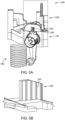
- the fluid injector system 100 has a connection port 192 that is configured to form a releasable fluid connection with at least a portion of the SUDS 190.
- the connection port 192 may be formed on the MUDS 130.
- the connection port 192 may be shielded by at least a portion of the housing 102 of the fluid injector system 100. For example, recessing the connection port 192 within the interior of the housing 102 may preserve the sterility of the connection port 192 by preventing or limiting a user or patient from touching and contaminating the portions of the connection port 192 that contact the fluid to be injected to the patient.
- connection port 192 is recessed within an opening 194 formed on the housing 102 of the fluid injector system 100, or the connection port 192 may have a shielding structure (not shown) that surrounds at least a portion of the connection port 192.
- the connection port 192 may be formed directly on the housing 102 and connected to the MUDS 130 by a fluid path (not shown).
- the SUDS 190 may be connected to the connection port 192, formed on at least a portion of the MUDS 130 and/or the housing 102.
- connection between the SUDS 190 and the connection port 192 is a releasable connection to allow the SUDS 190 to be selectively disconnected from the connection port 192 ( FIG. 3A ) and connected to the connection port 192 ( FIG. 3B ).
- the SUDS 190 may be disconnected from the connection port 192 and disposed after each fluid delivery procedure and a new SUDS 190 may be connected to the connection port 192 for a subsequent fluid delivery procedure.
- a waste inlet port 196 may be provided separately from the connection port 192.
- the waste inlet port 196 is in fluid communication with the waste reservoir 156.
- the waste reservoir 156 is provided separately from the SUDS 190 such that the fluid from the waste inlet port 196 can be delivered to the waste reservoir 156.
- At least a portion of the SUDS 190 may be releasably connected to or associated with the waste inlet port 196 for introducing waste fluid into the waste reservoir 156 during, for example, a priming operation that expels air from the SUDS 190.
- the waste reservoir 156 may have a viewing window 198 with indicia 200, such as graduated markings, that indicate the fill level of the waste reservoir 156.
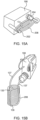
- the SUDS 190 has a fluid inlet port 202 that is configured for releasable connection with the connection port 192 (shown in FIG. 3A ).
- the fluid inlet port 202 receives fluid delivered from the fluid injector system 100.
- the fluid inlet port 202 is desirably a hollow, tubular structure, as shown in FIG. 4B .
- the SUDS 190 further has a waste outlet port 204 that is configured for releasable connection or association with the waste inlet port 196 (shown in FIG. 3A ).
- the waste outlet port 204 receives waste fluid and delivers such waste fluid to the waste reservoir 156 during, for example, a priming operation of the SUDS 190.
- the waste outlet port 204 is desirably a hollow, tubular structure, as shown in FIG. 4B .
- the waste outlet port 204 may be connected to, inserted into, or located in the waste inlet port 202 so that the waste fluid may flow through the waste inlet port 202 and continue into waste reservoir 156.
- the fluid inlet port 202 and the waste outlet port 204 may be spaced apart from each other by a spacer 206.
- the spacer 206 is dimensioned to position the fluid inlet port 202 and the waste outlet port 204 for alignment with the connection port 192 and the waste inlet port 196, respectively.
- the SUDS 190 is shown in FIG. 4A in a state after removal from packaging (not shown).
- the SUDS 190 Prior to use, the SUDS 190 is desirably packaged in a pre-sterilized, sealed package that protects the SUDS 190 from contamination with air or surface-borne contaminants.
- the sealed package and SUDS 190 may be sterilized after packaging.
- the SUDS 190 desirably has an asymmetrical structure, so that the user can only attach the SUDS 190 to the MUDS 130 in one orientation. In this manner, the user is prevented from attaching the fluid inlet port 202 to the waste inlet port 196.
- a fin 207 may be provided on at least a portion of the SUDS 190 to prevent erroneous insertion of the SUDS 190 in the connection port 192.
- the fin 207 may be formed on the spacer 206 proximate to the waste outlet port 204. In this manner, the fin 207 may interfere with the incorrect insertion of the SUDS 190 into the connection port 192. Structures and shapes other than fin 207 may be used to prevent erroneous insertion of the SUDS 190 into connection port 192,
- tubing 208 may be connected at its proximal end 210 to the fluid inlet port 202.
- the tubing 208 is configured to deliver fluid received from the fluid inlet port 202.
- the distal end 212 of the tubing 208 may have a connector 214 that is configured for connection with the waste outlet port 204 or a fluid path connected to the patient (not shown).
- the tubing 208 may be made from a flexible material, such as a medical grade plastic material, that allows the tubing 208 to be coiled.
- the connector 214 may be a luer-lock connector (either a male luer-lock connector or a female luer-lock connector depending on the desired application) or other medical connector configuration.
- the connector 214 may have a one-way valve to prevent backflow of fluid. Alternatively, a one-way valve may be located elsewhere in the SUDS 190 between fluid inlet port 202 and connector 214.
- the SUDS 190 may have a locking tab 216 that is configured for selectively locking the SUDS 190 with the fluid injector system 100 depending on the engagement of the locking tab 216 with at least a portion of the fluid injector system 100.
- the locking tab 216 may be a flexible tab that is deflectable between an engaged position and a disengaged position by deflecting at least a portion of the locking tab 216.
- the locking tab 216 may have a pressing surface 218 that, when pressed, causes the locking tab 216 to be deflected from the engaged position to the disengaged position for insertion and removal of the SUDS 190 from the fluid injector system 100.
- the locking tab 216 may be configured for releasable locking engagement with a receiving slot 217 on the MUDS 130 (shown in FIG. 4C ).
- the SUDS 190 may have a first annular skirt 224 extending circumferentially around a proximal end 226 of the fluid inlet port 202 and a second annular skirt 220 extending circumferentially around a distal end 222 of the fluid inlet port 202.
- the first and second annular skirts 224, 220 surround the fluid inlet port 202 to prevent inadvertent contact and contamination.
- the first annular skirt 224 may have one or more recesses 228 (shown in FIG. 4A ) extending through a sidewall thereof.
- the one or more recesses 228 may provide a locking interface with a corresponding locking element (not shown) on the fluid injector system 100.
- the second annular skirt 220 may have at least one indentation 230 (shown in FIG. 4A ) to facilitate grasping and handling of the SUDS 190.
- the second annular skirt 220 may have a textured surface having one or more ribs 232 (shown in FIG. 4A ) to facilitate gripping and handling of the SUDS 190.
- At least one annular seal 234 may be provided around the proximal end 226 of the fluid inlet port 202.
- the at least one annular seal 234 may seal the fluid inlet port 202 to prevent fluid from leaking through the SUDS 190.
- the at least one annular seal 234 may provide a fluid seal between the SUDS 190 and the MUDS 130 when they are fluidly connected with one another to allow fluid to flow from the MUDS 130 to the SUDS 190 without leaking.
- a one-way valve 236 may be provided within a lumen of the fluid inlet port 202 to prevent fluid from flowing in a reverse direction from the SUDS 190 into the MUDS 130.
- the SUDS 190 shown in FIG. 4A is shown connected to the fluid injector system 100. While FIG. 4C illustrates the connection port 192 formed on the MUDS 130, in other embodiments, the connection port 192 may be formed on a portion of the housing 102 (shown in FIG. 1 ).
- the fluid inlet port 202 of the SUDS 190 is connected to the connection port 192 to establish a fluid path in a direction of arrow F shown in FIG. 4C . Fluid passing through the fluid inlet port 202 flows through the one-way valve 236 and into tubing 208. Any fluid that may drip from the interface between the fluid inlet port 202 and the connection port 192 is collected in the waste reservoir 156.
- the waste reservoir 156 may be shaped to collect any fluid that may drip from the SUDS 190 when it is removed from the MUDS 130. Additionally, when the SUDS 190 is connected to the connection port 192, the outlet of the waste outlet port 204 is positioned within the waste inlet port 196 such that waste fluid from the tubing 208 may be discharged into the waste reservoir 156.
- the spacer 206 may define an insertion stop surface to define the depth of insertion of the SUDS 190 into the connection port 192.
- the fluid injector system 100 may have a sensor system 238 adapted to identify when the SUDS 190 is in fluid communication with the MUDS 130.
- the sensor system 238 may include at least one sensing element, such as a sensor fin 240, on the SUDS 190 and a corresponding sensor 242 on the fluid injector system 100 or MUDS 130.
- the sensor 242 may be configured to detect the presence and absence of the at least one sensor fin 240, or other sensing element.
- the sensing element, such as the at least one sensor fin 240 is formed on the locking tab 216 of the SUDS 190, such as shown in FIG. 4A .
- the sensing element such as the at least one sensor fin 240 may be formed on any portion of the SUDS 190.
- the sensor 242 may be an optical sensor that is seated and secured within a respective mount formed on the housing 102 of the fluid injector system 100.
- the sensor 242 may be electronically coupled to an electronic control device used to discretely control operation of the fluid injector system, such as the operation of the one or more piston elements, based, at least in part, on input from the sensor 242.
- the sensing element, such as the sensor fin 240 may have one or more reflective surfaces that reflect visible or infrared light to be detected by the sensor 242. In other embodiments, mechanical interaction between the sensing element and the sensor 242 may be used.
- the SUDS 190 may further include reuse prevention features (not shown).
- the SUDS 190 may include one or more breakable sensor elements, tabs, or structures that fold or break when the SUDS 190 is removed from the MUDS 130. Absence of these features may prevent reinsertion and reuse of the SUDS 190 after removal. In this manner, it can be assured that the SUDS 190 is only used for one fluid delivery procedure.
- a medical technician or user removes the disposable SUDS 190 from its packaging (not shown) and inserts the fluid inlet port 202 into the connection port 192 on the MUDS 130.
- the SUDS 190 must be inserted in the correct orientation, such that the fluid inlet port 202 is aligned for connection with the connection port 192, and the waste outlet port 204 is aligned for connection with the waste inlet port 196.
- the SUDS 190 may be secured to the MUDS 130 by inserting the locking tab 216 into the receiving slot 217 on the MUDS 130.
- the fluid injector system 100 (shown in FIG. 1 ) draws fluid into one or more of the plurality of syringes 132 of the MUDS 130 and performs an automatic priming operation for removing air from the MUDS 130 and the SUDS 190.
- fluid from the MUDS 130 is injected through the connection port 192 and into the tubing 208 of the SUDS 190.
- the fluid flows through the tubing 208 and through the waste outlet port 204 and into the waste reservoir 156.
- the medical technician disconnects the connector 214 from the waste outlet port 204.
- the connector 214 may then be connected to the patient through a catheter, vascular access device, needle, or additional fluid path set to facilitate fluid delivery to the patient.
- the SUDS 190 is disconnected from the patient and the MUDS 130 by disengaging the locking tab 216 of the SUDS 190 from the receiving slot 217 on the MUDS 130.
- the medical technician may then dispose of the SUDS 190.
- removing the SUDS 190 from the MUDS 130 causes reuse prevention features (not shown) to activate, thereby preventing reinsertion and reuse of the SUDS 190.
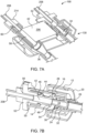
- connection interface between the SUDS 190 and the MUDS 130 is shown in accordance with another embodiment.
- the MUDS 130 has a connection port 192 that may be configured as a hollow, tubular structure having a luer lock connector 24 (either a male luer lock connector or a female luer lock connector depending on the desired application), extending from a distal end of the port 192 into an interior of the port 192. Accordingly, the proximal opening of the luer lock connector 24 is recessed within the interior of the port 192.
- the luer lock connector 24 may include screw threads 30 (shown in FIG. 7B ) for securing the MUDS 130 to the SUDS 190.
- the screw threads 30 may be positioned on an outer shroud 32 surrounding the luer lock connector 24, as shown in FIGS. 7A and 7B . Screw threads 30 may also be positioned on the luer lock connector 24 itself.
- the luer lock connector 24 defines a fluid passageway 34 (shown in FIG. 7B ) extending therethrough, from the proximal end of the connection port 192 to the distal opening thereof.
- the connection port 192 is depicted as including a luer lock connector 24, other styles of connectors, including, but not limited to, clip-in connectors, bayonet connectors, press fit connectors, and the like, may be used within the scope of the present disclosure.
- the connector 24 for the connection port 192 is desirably a non-standard connector (e.g. a connector with an unusual size or shape) so that connectors produced by third parties cannot be attached.
- the MUDS 130 has a waste inlet port 196 (shown in FIG. 6 ) that may also be configured as a hollow, tubular structure.
- the waste inlet port 196 includes a tapered distal nozzle 36 attached to a fluid conduit, such as flexible tubing 208, formed from a medical grade polymer, that connects the waste inlet port 196 to the waste reservoir 156 (shown in FIG. 2 ).
- the MUDS 130 is adapted for connecting to the SUDS 190, which is disposed of after a single use. It is noted that the SUDS 190 is shown in FIG. 6 in a state after removal from packaging (not shown). Prior to use, the SUDS 190 is desirably packaged in a pre-sterilized, sealed package that protects the SUDS 190 from contamination with air or surface-borne contaminants.
- the SUDS 190 may have two or more ports, corresponding to the connection port 192 and waste inlet port 196 of the MUDS 130.
- the ports of the SUDS 190 are equivalent to the fluid inlet port 202 and the waste outlet port 204 of the SUDS 190 described with reference to FIGS. 4A-4B .
- the ports 202, 204 may be provided in an enclosure 42 suitable for receipt within the housing 20 of the MUDS 130, as shown in FIG. 7B .
- the enclosure 42 desirably has an asymmetrical structure, so that the user can only attach the SUDS 190 to the MUDS 130 in one orientation only.
- connection port 192 of the MUDS 130 is prevented from attaching the connection port 192 of the MUDS 130 to the SUDS 190 waste outlet port 204.
- the ports 202, 204 and enclosure 42 of the SUDS 190 may be made from a material suitable for medical applications, such as medical grade plastic.
- the tubing 208 of the SUDS 190 is connected between the proximal end of the fluid inlet port 202 and the end of the waste outlet port 204 through check valves.
- the tubing 208 may be provided in a wound or coiled configuration for easy packaging and maneuverability.
- the SUDS 190 fluid inlet port 202 is a hollow, tubular structure configured for insertion in the connection port 192 of the MUDS 130.
- the SUDS 190 fluid inlet port 202 includes a tubular conduit, such as a luer lock connector 44, defining a fluid passageway 46 extending from a proximal end of the port 202, located adjacent to the MUDS 130, and the distal end of the port 204, connected to the tubing 208.
- the luer lock connector 44 is adapted to connect to the luer lock connector 24 of the MUDS 130.
- connection port 192 of the MUDS 130 is in fluid communication with the fluid inlet port 202 of the SUDS 190.
- the luer lock connector 44 may include a thumbwheel 52 for securing the connection port 192 of the MUDS 130 to the SUDS 190 fluid inlet port 202.
- the thumbwheel 52 may be integrally formed with the luer lock connector 44 or may be a separate structure fixedly connected to the luer lock connector 44 by conventional means.
- the thumbwheel 52 rotates the luer lock connector 44 causing tabs 54, extending therefrom, to engage the corresponding screw threads 30 in the connection port 192.
- the tubing 208 is connected to the fluid inlet port 202 through an opening 56 on the thumbwheel 52, such that a continuous fluid connection is established from the MUDS 130 to the tubing 208.
- the SUDS 190 also includes the SUDS 190 waste outlet port 204.
- the SUDS waste outlet port 204 has a fluid passageway 58, defined by a tubular conduit 60, extending between the waste inlet port 196 of the MUDS 130, and the tubing 208.
- the tubing 208 may not be directly connected to the waste inlet port 196 of the MUDS 130. Instead, the tubular conduit 60 of the SUDS 190 may separate the tubing 208 from the MUDS 130, thereby ensuring that the tubing 208 and the connector 214 are isolated from the waste inlet port 196 of the MUDS 130.
- the tubular conduit 60 may be recessed from the waste inlet port 196 of the MUDS 130 by a portion of the single-use connector enclosure 42, to reduce the likelihood of contamination.
- the tubular conduit 60 may also be angled, relative to the horizontal, to facilitate fluid flow through the SUDS 190 waste outlet port 204 and into the waste inlet port 196 of the MUDS 130.
- the SUDS 190 may further include reuse prevention features (not shown).
- the SUDS 190 may include breakable tabs or structures that fold or break when the SUDS 190 is removed from the MUDS 130. In this manner, it can be assured that the SUDS 190 is only used for one fluid delivery procedure.
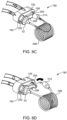
- FIGS. 8A-8F a method of operation of the embodiment of the connection assembly between the SUDS 190 and MUDS 130 depicted in FIGS. 6-7B will now be described in detail.
- a medical technician or user removes the disposable SUDS 190 from its packaging and inserts the SUDS 190 into the corresponding MUDS 130.
- the SUDS 190 must be inserted in the correct orientation, such that the connection port 192 of the MUDS 130 engages the SUDS 190 fluid inlet port 202, and the waste inlet port 196 of the MUDS 130 engages the SUDS 190 waste outlet port 204. As shown in FIG.
- the medical technician then rotates the thumbwheel 52 to secure the SUDS 190 to the MUDS 130.
- the fluid injector system 100 (shown in FIG. 1 ) draws fluid into one or more of the plurality of syringes 132 of the MUDS 130 and performs an automatic priming operation ( FIG. 8C ) for removing air from the MUDS 130 and the SUDS 190.
- an automatic priming operation FIG. 8C
- fluid from the MUDS 130 is injected through the connection port 192 and into the tubing 208 of the SUDS 190.
- the fluid flows through the tubing 208 and through the waste outlet port 204 and into the waste reservoir 156.
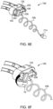
- the medical technician disconnects the connector 214 from the waste outlet port 204 ( FIG. 8D ).
- the connector 214 may then be connected to the patient through a catheter, vascular access device, or additional fluid path set to facilitate fluid delivery to the patient ( FIG. 8E ).
- the user disconnects the connector 214 rotates the thumbwheel 52 to remove the SUDS 190 from the MUDS 130 ( FIG. 8F ).
- the medical technician may then dispose of the SUDS 190.
- removing the SUDS 190 from the MUDS 130 causes reuse prevention features (not shown), such as tabs extending from a portion of the SUDS 190, to fold or break, preventing reinsertion of the SUDS 190.
- the SUDS 190 includes a cannula port 62 for receiving a needle cannula 129 connected to a connector 214.
- the cannula 129 used for fluid delivery to a patient, can be inserted into the cannula port 62 after being removed from the patient.
- the cannula port 62 may cover a contaminated end of the cannula 129 during disposal of the cannula 129.
- the single-use enclosure 42 is desirably long enough so that the entire length of the needle cannula 129 may be inserted in the enclosure 42 for a safe disposal.
- FIGS. 10A and 10B a further embodiment of a connector assembly having a SUDS 190 and a MUDS 130 is illustrated.
- the connector assembly is provided in a vertical orientation with the connection port 192 of the MUDS 130 positioned above the waste inlet port 196.
- the MUDS 130 includes a drip channel 64 extending between the connection port 192 and waste inlet port 196. Any fluid leaking from the connection port 192 is directed downward through the drip channel 64 by gravity. The drip channel 64 exits into the waste inlet port 196. Accordingly, any fluid expelled from the drip channel 64 is directed through the waste inlet port 196 and is collected in the waste reservoir 156.
- the MUDS 130 may be provided with an absorbent material, such as an absorbent pad 66 shown in FIG. 10C , surrounding a portion of the connection port 192 and the waste inlet port 196.
- the absorbent material is provided to absorb any fluid drips during removal of the SUDS 190 for improved drip management.
- the connector assembly having a SUDS 190 and a MUDS 130 having a plurality of press-fit connectors is illustrated.
- the SUDS 190 includes a fluid inlet port 202 and waste outlet port 204.
- the SUDS 190 includes disconnection tabs 68, rather than a thumbwheel.
- the SUDS 190 also includes an alignment structure 70 extending from the enclosure 42 of the SUDS 190 and is configured for insertion in a corresponding slot 72 of the MUDS 130 (shown in FIG. 11B ).
- the SUDS 190 is inserted into and aligned with the MUDS 130 by alignment channels 71.
- the disconnection tabs 68 are integrally formed with a tubular shroud 74 having an inwardly extending flange 76 at one end thereof.
- the shroud 74 surrounds a tubular conduit 80 on the SUDS 190.
- connection assembly having a MUDS 130 and SUDS 190 with disconnection tabs 68 described above, may also be provided in a vertical configuration.
- the MUDS 130 includes the connection port 192 and waste inlet port 196, as described in previous embodiments.
- the connection port 192 includes a co-molded sealing surface 82 for sealing between the SUDS 190 and the MUDS 130.
- the SUDS 190 includes external alignment surfaces 84, integrally formed with the enclosure 42, for correctly aligning the SUDS 190 and the MUDS 130.
- the alignment surfaces 84 also recess the fluid inlet port 202 and the waste outlet port 204 of the SUDS 190 to reduce the possibility of contamination prior to use.
- the tubing 208 may be wound about a holding structure 133, such as a spool or frame member, for ensuring that the tubing 208 does not unwind while being removed from its packaging or when the SUDS 190 is being connected to the MUDS 130.
- the tubing 208 may further include a removable external clip 135. The clip 135 connects about the wound tubing 208 to prevent the tubing 208 from unwinding during removal from packaging or auto-priming.
- the tubing 208 is provided with uncoiled portions 137 to keep the tubing 208 away from the SUDS 190.
- a coiled portion 139 of the tubing 208 hangs below the un-coiled portions 137, when the SUDS 190 is connected to the MUDS 130.
- an electronic control device 900 may be associated with fluid injector system 100 to control the filling and delivery operations.
- the electronic control device 900 may control the operation of various valves, piston members, and other elements to effect a desired filling or delivery procedure.
- the electronic control device 900 may include a variety of discrete computer-readable media components.
- this computer-readable media may include any media that can be accessed by the electronic control device 900, such as volatile media, non-volatile media, removable media, non-removable media, transitory media, non-transitory media, etc.
- this computer-readable media may include computer storage media, such as media implemented in any method or technology for storage of information, such as computer-readable instructions, data structures, program modules, or other data; random access memory (RAM), read only memory (ROM), electrically erasable programmable read only memory (EEPROM), flash memory, or other memory technology; CD-ROM, digital versatile disks (DVDs), or other optical disk storage; magnetic cassettes, magnetic tape, magnetic disk storage, or other magnetic storage devices; or any other medium which can be used to store the desired information and which can be accessed by the electronic control device 900.
- RAM random access memory
- ROM read only memory
- EEPROM electrically erasable programmable read only memory
- flash memory or other memory technology
- CD-ROM compact discs
- DVDs digital versatile disks
- magnetic cassettes magnetic tape, magnetic disk storage, or other magnetic storage devices; or any other medium which can be used to store the desired information and which can be accessed by the electronic control device 900.
- this computer-readable media may include communications media, such as computer-readable instructions, data structures, program modules, or other data in a modulated data signal, such as a carrier wave or other transport mechanism and include any information delivery media, wired media (such as a wired network and a direct-wired connection), and wireless media (such as acoustic signals, radio frequency signals, optical signals, infrared signals, biometric signals, bar code signals, etc.).
- communications media such as computer-readable instructions, data structures, program modules, or other data in a modulated data signal, such as a carrier wave or other transport mechanism and include any information delivery media, wired media (such as a wired network and a direct-wired connection), and wireless media (such as acoustic signals, radio frequency signals, optical signals, infrared signals, biometric signals, bar code signals, etc.).
- wired media such as a wired network and a direct-wired connection
- wireless media such as acoustic signals, radio frequency signals, optical signals, infrared
- the electronic control device 900 further includes a system memory 908 with computer storage media in the form of volatile and non-volatile memory, such as ROM and RAM.
- a basic input/output system (BIOS) with appropriate computer-based routines assists in transferring information between components within the electronic control device 900 and is normally stored in ROM.
- the RAM portion of the system memory 908 typically contains data and program modules that are immediately accessible to or presently being operated on by the processing unit 904, e.g., an operating system, application programming interfaces, application programs, program modules, program data, and other instruction-based computer-readable codes.
- the electronic control device 900 may also include other removable or non-removable, volatile or non-volatile, transitory or non-transitory computer storage media products.
- the electronic control device 900 may include a non-removable memory interface 910 that communicates with and controls a hard disk drive 912, e.g., a non-removable, non-volatile magnetic medium; and a removable, non-volatile memory interface 914 that communicates with and controls a magnetic disk drive unit 916 (which reads from and writes to a removable, non-volatile magnetic disk 918), an optical disk drive unit 920 (which reads from and writes to a removable, non-volatile optical disk 922, such as a CD ROM), a Universal Serial Bus (USB) port 921 for use in connection with a removable memory card, etc.
- a non-removable memory interface 910 that communicates with and controls a hard disk drive 912, e.g., a non-removable, non-vola
- removable or non-removable, volatile or non-volatile computer storage media can be used in the exemplary computing system environment 902, including, but not limited to, magnetic tape cassettes, DVDs, digital video tape, solid state RAM, solid state ROM, etc.
- These various removable or non-removable, volatile or non-volatile magnetic media are in communication with the processing unit 904 and other components of the electronic control device 900 via the system bus 906.
- the drives and their associated computer storage media discussed above and illustrated in FIG. 17 , provide storage of operating systems, computer-readable instructions, application programs, data structures, program modules, program data, and other instruction-based, computer-readable code for the electronic control device 900 (whether duplicative or not of this information and data in the system memory 908).
- a user may enter commands, information, and data into the electronic control device 900 through certain attachable or operable input devices, such as the user interface 124 shown in FIG. 1 , via a user input interface 928.
- a variety of such input devices may be utilized, e.g., a microphone, a trackball, a joystick, a touchpad, a touch-screen, a scanner, etc., including any arrangement that facilitates the input of data, and information to the electronic control device 900 from an outside source.
- these and other input devices are often connected to the processing unit 904 through the user input interface 928 coupled to the system bus 906, but may be connected by other interface and bus structures, such as a parallel port, game port, or a USB.
- data and information can be presented or provided to a user in an intelligible form or format through certain output devices, such as a monitor 930 (to visually display this information and data in electronic form), a printer 932 (to physically display this information and data in print form), a speaker 934 (to audibly present this information and data in audible form), etc. All of these devices are in communication with the electronic control device 900 through an output interface 936 coupled to the system bus 906. It is envisioned that any such peripheral output devices be used to provide information and data to the user.
- the electronic control device 900 may operate in a network environment 938 through the use of a communications device 940, which is integral to the electronic control device 900 or remote therefrom.
- This communications device 940 is operable by and in communication with the other components of the electronic control device 900 through a communications interface 942.
- the electronic control device 900 may connect with or otherwise communicate with one or more remote computers, such as a remote computer 944, which may be a personal computer, a server, a router, a network personal computer, a peer device, or other common network nodes, and typically includes many or all of the components described above in connection with the electronic control device 900.
- the computer 944 may operate within and communicate through a local area network (LAN) and a wide area network (WAN), but may also include other networks such as a virtual private network (VPN), an office network, an enterprise network, an intranet, the Internet, etc.
- LAN local area network
- WAN wide area network
- VPN virtual private network
- the electronic control device 900 includes, or is operable to execute appropriate custom-designed or conventional software to perform and implement the processing steps of the method and system of the present disclosure, thereby forming a specialized and particular computing system. Accordingly, the presently-invented method and system may include one or more electronic control devices 900 or similar computing devices having a computer-readable storage medium capable of storing computer-readable program code or instructions that cause the processing unit 904 to execute, configure, or otherwise implement the methods, processes, and transformational data manipulations discussed hereinafter in connection with the present disclosure.
- the electronic control device 900 may be in the form of a personal computer, a personal digital assistant, a portable computer, a laptop, a palmtop, a mobile device, a mobile telephone, a server, or any other type of computing device having the necessary processing hardware to appropriately process data to effectively implement the presently-invented computer-implemented method and system.
- system may utilize databases physically located on one or more computers which may or may not be the same as their respective servers.
- programming software on electronic control device 900 can control a database physically stored on a separate processor of the network or otherwise.
- the electronic control device 900 may be programmed so that automatic refill occurs based upon a preprogrammed trigger minimum volume in the respective syringes 132. For example, when the volume of fluid remaining in at least one of the syringes 132 is less than a programmed volume, a syringe refill procedure is automatically initiated by the electronic control device 900.
- the electronic control device 900 associated with the fluid injector system 100 may determine that the preprogrammed trigger minimum volume has been reached by tracking the fluid volume dispensed from the respective syringes 132 during operation of the fluid injector system 100.
- fluid level sensors may be incorporated into the fluid injector system 100 and inputs from these fluid level sensors may be provided to the electronic control device 900 so that the electronic control device 900 may determine when the preprogrammed trigger minimum volume has been reached in at least one of the syringes 132.
- the fill volume and rate of refill can be preprogrammed in the electronic control device 900.
- the automatic refill procedure can be stopped either automatically by the electronic control device 900 or may be manually interrupted.
- an automatic refill procedure may be initiated when, at the completion of a fluid injection procedure, there is not enough fluid in at least one of the syringes 132 to perform the next programmed fluid injection procedure.
- the fluid injector system 100 may have an indicator, such as an audible and/or visual indicator, to indicate to the operator that a change of the bulk fluid source 120 is necessary before the fluid injector system 100 may be used.
Landscapes
- Health & Medical Sciences (AREA)
- Heart & Thoracic Surgery (AREA)
- Animal Behavior & Ethology (AREA)
- General Health & Medical Sciences (AREA)
- Biomedical Technology (AREA)
- Engineering & Computer Science (AREA)
- Hematology (AREA)
- Life Sciences & Earth Sciences (AREA)
- Veterinary Medicine (AREA)
- Anesthesiology (AREA)
- Public Health (AREA)
- Vascular Medicine (AREA)
- Pulmonology (AREA)
- Infusion, Injection, And Reservoir Apparatuses (AREA)
- External Artificial Organs (AREA)
- Orthopedics, Nursing, And Contraception (AREA)
Claims (13)
- Medizinischer Verbinder (190), umfassend:einen Fluideinlassanschluss (202) zum entfernbaren Eingriff mit einem Verbindungsanschluss (192) eines Fluidinjektorsystems (100), das ein Gehäuse (102) aufweist, wobei der Verbindungsanschluss an einem Einwegsatz zur Mehrfachverwendung (MUDS - multi-use disposable set) (130) ausgebildet ist, der entfernbar mit dem Fluidinjektorsystem (100) verbunden ist, um eine Fluidverbindung damit herzustellen, wobei der Verbindungsanschluss (192) in einer an dem Gehäuse (102) ausgebildeten Öffnung ausgespart ist,einen Abfallprodukteauslassanschluss (204), der für den entfernbaren Eingriff mit einem Abfallprodukteeinlassanschluss (196) eines Fluidinjektorsystems (100) ausgestaltet ist, um eine Fluidverbindung damit herzustellen,eine Patientenfluidleitung (208), die an einem ersten Ende (210) mit dem Fluideinlassanschluss (202) verbunden ist und an einem zweiten Ende (212) über einen Patientenfluidleitungsverbinder (214) entfernbar mit dem Abfallprodukteauslassanschluss (204) verbunden ist,wodurch zwischen dem Fluideinlassanschluss (202) und dem Abfallproduktauslassanschluss (204) eine Fluidverbindung hergestellt wird,wobei die Fluidströmung durch die Patientenfluidleitung (208) von dem ersten Ende (210) zu dem zweiten Ende (212) unidirektional ist,wobei der medizinische Verbinder ferner Folgendes umfasst:einen Verriegelungsmechanismus (216) zum entfernbaren Befestigen des medizinischen Verbinders (190) mit dem MUDS (130), wobei der Verriegelungsmechanismus (216) eine flexible Lasche (216) umfasst, die zwischen einer Eingriffsposition mit einem Aufnahmeschlitz (217) an dem MUDS (130) und einer ausgerückten Position auslenkbar ist, indem mindestens ein Abschnitt der flexiblen Lasche (216) ausgelenkt wird, undmindestens ein Sensorelement (240), das an der flexiblen Lasche (216) eine Erfassungsfinne (240) umfasst, die eine oder mehrere Reflexionsflächen hat, die sichtbares oder Infrarotlicht reflektieren, das von mindestens einem Sensor (242) zu erfassen ist, der in einer jeweiligen Halterung sitzt und befestigt ist, die an dem Gehäuse (102) des Fluidinjektorsystems (100) ausgebildet ist, um ein Vorliegen oder ein Nichtvorliegen der Erfassungsfinne (240) zu erfassen, wobei das Erfassen des Vorliegens des mindestens einen Sensorelements (240) durch den mindestens einen Sensor (242) angibt, dass der medizinische Verbinder (190) in den Verbindungsanschluss (192) eingeführt oder in diesem installiert ist,und wobei die Patientenfluidleitung (208) und der Patientenfluidleitungsverbinder (214) dazu ausgestaltet sind, von dem Abfallprodukteauslassanschluss (204) getrennt zu werden, um einem Katheter, einer Gefäßzugangsvorrichtung, einer Nadel oder einem zusätzlichen Fluidweg Fluid von dem Fluideinlassanschluss (202) zuzuführen, während der Abfallprodukteauslassanschluss (204) mit dem Abfallprodukteeinlassanschluss (196) des Fluidinjektorsystems (100) in Eingriff bleibt.
- Medizinischer Verbinder (190) nach Anspruch 1, wobei die flexible Lasche (216) eine Druckfläche (218) hat, die, wenn darauf gedrückt wird, die flexible Lasche (216) aus der Eingriffsposition in die ausgerückte Position auslenkt.
- Medizinischer Verbinder (190) nach Anspruch 1, wobei der Fluideinlassanschluss (202) eine Schürze (220) umfasst, die mindestens einen Abschnitt des Fluideinlassanschlusses (202) umgibt.
- Medizinischer Verbinder (190) nach Anspruch 3, wobei die Schürze (220) mindestens eine Vertiefung (230) hat, um die Handhabung des medizinischen Verbinders (190) zu erleichtern, oder
wobei die Schürze (220) eine oder mehrere Rippen (232) hat, die von einer Außenfläche der Schürze (220) vorragen. - Medizinischer Verbinder (190) nach Anspruch 1, wobei der Fluideinlassport (202) so gestaltet ist, dass er eine Verbindung mit dem Abfallprodukteinlassanschluss (196) des MUDS (130) verhindert, und wobei der Abfallproduktauslassanschluss (204) so gestaltet ist, dass er eine Verbindung mit dem Verbindungsanschluss (192) des MUDS (130) verhindert.
- Medizinischer Verbinder (190) nach Anspruch 1, wobei der medizinische Verbinder (190) eine asymmetrische Gestalt hat, so dass der medizinische Verbinder (190) nur in einer Ausrichtung mit dem MUDS (130) verbindbar ist, wobei der medizinische Verbinder (190) vorzugsweise ferner mindestens eine Finne (207) umfasst, um eine fehlerhafte Verbindung des medizinischen Verbinders (190) mit dem MUDS (130) zu verhindern.
- Medizinischer Verbinder (190) nach Anspruch 1, wobei das zweite Ende (212) der Patientenfluidleitung (208) und der Patientenfluidleitungsverbinder (214) unter Aufrechterhaltung der Sterilität des zweiten Endes (212) für den entfernbaren Eingriff mit dem Abfallproduktauslassanschluss (204) ausgestaltet sind.
- Medizinischer Verbinder (190) nach Anspruch 7, wobei der Patientenfluidleitungsverbinder (214) in Fluidverbindung mit dem Abfallproduktauslassanschluss (204) in Fluidverbindung ist, wenn er mit dem Abfallproduktauslassanschluss (204) in Eingriff ist.
- Medizinischer Verbinder (190) nach Anspruch 7, wobei der Patientenfluidleitungsverbinder (214) ein Luer-Lock-Verbinder ist.
- Medizinischer Verbinder (190) nach Anspruch 1, ferner umfassend ein Einwegventil (236), das zur Aufrechterhaltung von unidirektionaler Strömung durch den Fluideinlassanschluss (202) in die Patientenfluidleitung (208) ausgestaltet ist.
- Medizinischer Verbinder (190) nach Anspruch 1, wobei der Fluideinlassanschluss (202) mindestens eine Dichtung (234) hat, um eine fluiddichte Verbindung zwischen dem Fluideinlassanschluss (202) und dem Verbindungsanschluss (192) zu bilden.
- Medizinischer Verbinder (190) nach Anspruch 1, ferner umfassend:einen sich zwischen dem Fluideinlassanschluss (202) und dem Abfallproduktauslassanschluss (204) erstreckenden Abstandhalter (206),wobei die Patientenfluidleitung (208) einen Patientenfluidleitungsverbinder (214) umfasst, der mit dem zweiten Ende (212) der Patientenfluidleitung (208) verbunden ist,
undwobei der Patientenfluidleitungsverbinder (214) für die entfernbare Fluidverbindung mit dem Abfallproduktauslassanschluss (204) ausgestaltet ist, um einem Patienten Fluid zuzuführen. - Verfahren zum automatischen Entlüften eines Verbinders (190) eines Einwegsatzes zur einmaligen Verwendung (SUDS - single-use disposable set), wobei das Verfahren Folgendes umfasst:fluidisches Verbinden eines Fluideinlassanschlusses (202) des SUDS-Verbinders (190) mit einem Verbindungsanschluss (192) eines Fluidinjektorsystems (100), das ein Gehäuse (102) aufweist, wobei der Verbindungsanschluss (192) an einem Einwegsatz zur Mehrfachverwendung (MUDS - multi-use disposable set) (130) ausgebildet ist, der entfernbar mit dem Fluidinjektorsystem (100) verbunden ist, um eine Fluidverbindung damit herzustellen, wobei der Verbindungsanschluss (192) in einer an dem Gehäuse (102) ausgebildeten Öffnung ausgespart ist,Herstellen einer Fluidverbindung zwischen einem Abfallprodukteauslassanschluss (204) des SUDS-Verbinders (190) und einem Abfallprodukteeinlassanschluss (196) eines Fluidinjektorsystems (100),Erfassen durch mindestens einen Sensor (242), der in einer jeweiligen Halterung sitzt und befestigt ist, die an dem Gehäuse (102) des Fluidinjektorsystems (100) ausgebildet ist, des Vorliegens oder Nichtvorliegens einer Erfassungsfinne (240), die eine oder mehrere Reflexionsflächen hat, die sichtbares oder Infrarotlicht reflektieren, das von dem mindestens einen Sensor (242) zu erfassen ist, wobei die Erfassungsfinne (240) an einer flexiblen Lasche (216) an dem SUDS-Verbinder (190) angeordnet ist, wodurch angegeben wird, dass der SUDS-Verbinder (190) fluidisch mit dem Verbinderanschluss (192) des MUDS (130) verbunden ist,wenn das Vorliegen der Erfassungsfinne (240) von dem mindestens einen Sensor (242) erfasst wird, automatisches Entlüften des SUDS-Verbinders (190) durch das Fluidinjektorsystem (100), indem dem Abfallprodukteauslassanschluss (204) Fluid von dem Fluideinlassanschluss (202) durch eine Patientenfluidleitung (208) zugeführt wird, undTrennen eines Endes (212) der Patientenfluidleitung (208) von dem Abfallprodukteauslassanschluss (204), während der Abfallprodukteauslassanschluss (204) mit dem Abfallprodukteeinlassanschluss (196) des MUDS (130) in Eingriff bleibt,wobei das Verfahren vorzugsweise ferner das Verriegeln des SUDS-Verbinders mit dem MUDS vor dem Entlüften des SUDS-Verbinders umfasst.
Priority Applications (4)
| Application Number | Priority Date | Filing Date | Title |
|---|---|---|---|
| RS20241134A RS66068B1 (sr) | 2014-01-10 | 2015-01-09 | Priključak kompleta za jednokratnu upotrebu |
| SI201532036T SI3092017T1 (sl) | 2014-01-10 | 2015-01-09 | Konektorski komplet za enkratno uporabo |
| HRP20241397TT HRP20241397T1 (hr) | 2014-01-10 | 2015-01-09 | Konektor za komplet za jednokratnu upotrebu |
| EP24181032.4A EP4487884A3 (de) | 2014-01-10 | 2015-01-09 | Einweg-set-verbinder zum einmaligen gebrauch |
Applications Claiming Priority (2)
| Application Number | Priority Date | Filing Date | Title |
|---|---|---|---|
| US201461925940P | 2014-01-10 | 2014-01-10 | |
| PCT/US2015/010825 WO2015106107A1 (en) | 2014-01-10 | 2015-01-09 | Single-use disposable set connector |
Related Child Applications (2)
| Application Number | Title | Priority Date | Filing Date |
|---|---|---|---|
| EP24181032.4A Division-Into EP4487884A3 (de) | 2014-01-10 | 2015-01-09 | Einweg-set-verbinder zum einmaligen gebrauch |
| EP24181032.4A Division EP4487884A3 (de) | 2014-01-10 | 2015-01-09 | Einweg-set-verbinder zum einmaligen gebrauch |
Publications (3)
| Publication Number | Publication Date |
|---|---|
| EP3092017A1 EP3092017A1 (de) | 2016-11-16 |
| EP3092017A4 EP3092017A4 (de) | 2017-08-09 |
| EP3092017B1 true EP3092017B1 (de) | 2024-07-17 |
Family
ID=53524367
Family Applications (2)
| Application Number | Title | Priority Date | Filing Date |
|---|---|---|---|
| EP15735396.2A Active EP3092017B1 (de) | 2014-01-10 | 2015-01-09 | Voreingestellte verbinder zur einmaligen verwendung |
| EP24181032.4A Pending EP4487884A3 (de) | 2014-01-10 | 2015-01-09 | Einweg-set-verbinder zum einmaligen gebrauch |
Family Applications After (1)
| Application Number | Title | Priority Date | Filing Date |
|---|---|---|---|
| EP24181032.4A Pending EP4487884A3 (de) | 2014-01-10 | 2015-01-09 | Einweg-set-verbinder zum einmaligen gebrauch |
Country Status (30)
| Country | Link |
|---|---|
| US (3) | US10549084B2 (de) |
| EP (2) | EP3092017B1 (de) |
| JP (3) | JP6993085B2 (de) |
| KR (2) | KR101996709B1 (de) |
| CN (3) | CN106102796B8 (de) |
| AU (5) | AU2015204608C1 (de) |
| BR (1) | BR112016015783B1 (de) |
| CA (2) | CA2936234C (de) |
| CL (1) | CL2016001720A1 (de) |
| DK (1) | DK3092017T3 (de) |
| ES (1) | ES2989494T3 (de) |
| FI (1) | FI3092017T3 (de) |
| HR (1) | HRP20241397T1 (de) |
| HU (1) | HUE068725T2 (de) |
| IL (3) | IL302231B1 (de) |
| LT (1) | LT3092017T (de) |
| MA (1) | MA39181B1 (de) |
| MX (2) | MX390270B (de) |
| MY (1) | MY177223A (de) |
| NZ (1) | NZ722989A (de) |
| PH (1) | PH12016501361A1 (de) |
| PL (1) | PL3092017T3 (de) |
| PT (1) | PT3092017T (de) |
| RS (1) | RS66068B1 (de) |
| RU (1) | RU2703066C9 (de) |
| SA (1) | SA516371474B1 (de) |
| SG (1) | SG11201605540VA (de) |
| SI (1) | SI3092017T1 (de) |
| WO (1) | WO2015106107A1 (de) |
| ZA (1) | ZA201605306B (de) |
Families Citing this family (74)
| Publication number | Priority date | Publication date | Assignee | Title |
|---|---|---|---|---|
| EP4628145A3 (de) * | 2015-01-09 | 2025-12-03 | Bayer Healthcare LLC | System zur abgabe mehrerer flüssigkeiten mit einwegset zur mehrfachverwendung und funktionen davon |
| ES3024283T3 (en) | 2015-08-13 | 2025-06-04 | Bayer Healthcare Llc | Systems for determining, and devices for indicating, viable life of replaceable components thereof and methods therefor |
| ES2952520T3 (es) * | 2015-08-28 | 2023-10-31 | Bayer Healthcare Llc | Sistema y procedimiento para la verificación del llenado del fluido de la jeringa y el reconocimiento de imágenes de las características del sistema inyector de energía |
| US10898638B2 (en) | 2016-03-03 | 2021-01-26 | Bayer Healthcare Llc | System and method for improved fluid delivery in multi-fluid injector systems |
| WO2018017447A1 (en) * | 2016-07-18 | 2018-01-25 | Bayer Healthcare Llc | Fluid injector and patient set therefor |
| US12263326B2 (en) | 2016-11-14 | 2025-04-01 | Bayer Healthcare Llc | Methods and systems for verifying the contents of a syringe used for medical fluid delivery |
| AR110862A1 (es) * | 2017-02-01 | 2019-05-08 | Bayer Healthcare Llc | Reconocimiento de frecuencia acústica en vías intracorporales |
| CA3068658A1 (en) | 2017-08-18 | 2019-02-21 | Bayer Healthcare Llc | System, method, and computer program product for predictive maintenance |
| CN110869071B (zh) | 2017-08-31 | 2023-05-02 | 拜耳医药保健有限公司 | 流体注入器系统中的动态压力控制的方法 |
| JP7252143B2 (ja) | 2017-08-31 | 2023-04-04 | バイエル・ヘルスケア・エルエルシー | 駆動部材の位置及び流体注入器システムの機械的較正のためのシステム及び方法 |
| EP3676854A1 (de) | 2017-08-31 | 2020-07-08 | Bayer Healthcare LLC | Beurteilung der impedanz eines flüssigkeitspfades zur verbesserung der flüssigkeitsabgabeleistung |
| JP7317724B2 (ja) | 2017-08-31 | 2023-07-31 | バイエル・ヘルスケア・エルエルシー | 液注入器システムの容積補償システムおよび方法 |
| EP3675931B1 (de) | 2017-08-31 | 2021-08-11 | Bayer Healthcare LLC | System und verfahren zur einspritzdruckkalibrierung |
| JP2019122461A (ja) * | 2018-01-12 | 2019-07-25 | 株式会社三洋物産 | 遊技機 |
| JP2019122463A (ja) * | 2018-01-12 | 2019-07-25 | 株式会社三洋物産 | 遊技機 |
| JP2019136401A (ja) * | 2018-02-14 | 2019-08-22 | 株式会社三洋物産 | 遊技機 |
| JP2019136400A (ja) * | 2018-02-14 | 2019-08-22 | 株式会社三洋物産 | 遊技機 |
| JP2019136398A (ja) * | 2018-02-14 | 2019-08-22 | 株式会社三洋物産 | 遊技機 |
| JP2019136399A (ja) * | 2018-02-14 | 2019-08-22 | 株式会社三洋物産 | 遊技機 |
| PL3758777T3 (pl) * | 2018-02-27 | 2023-06-12 | Bayer Healthcare, Llc | Mechanizm sprzęgający tłoczek strzykawki |
| JP7515401B2 (ja) * | 2018-04-10 | 2024-07-12 | バイエル・ヘルスケア・エルエルシー | 投与ラインへの造影剤注入プロトコール分の予備充填 |
| JP7479291B2 (ja) | 2018-04-10 | 2024-05-08 | バイエル・ヘルスケア・エルエルシー | 電動流体注入システムの使用と関連付けられた衛生慣行を監視するためのシステムおよび方法 |
| JP7705244B2 (ja) | 2018-04-10 | 2025-07-09 | バイエル・ヘルスケア・エルエルシー | 電動式流体インジェクタシステムを使用して血管アクセスを試験するためのシステムおよび方法 |
| US20210023298A1 (en) | 2018-04-19 | 2021-01-28 | Bayer Healthcare Llc | Method of removal of gas from reservoir |
| AU2019256461B2 (en) | 2018-04-19 | 2024-03-07 | Bayer Healthcare Llc | System and method for air detection in fluid injector |
| WO2020046869A1 (en) | 2018-08-28 | 2020-03-05 | Bayer Healthcare Llc | Fluid injector system, method of preventing fluid backflow, and computer program product |
| CN112638461B (zh) | 2018-08-28 | 2023-01-24 | 拜耳医药保健有限公司 | 利用压力测量来检测患者管线的重复使用 |
| AU2019332923A1 (en) | 2018-08-28 | 2021-02-11 | Bayer Healthcare Llc | Fluid injector system with improved ratio performance |
| GB201816769D0 (en) * | 2018-10-15 | 2018-11-28 | Meditech Endoscopy Ltd | Connector |
| MX2021007370A (es) | 2018-12-20 | 2021-07-15 | Bayer Healthcare Llc | Mecanismos para impedir la reconexion de conectores destinados a un unico uso. |
| EP3921014B1 (de) * | 2019-02-04 | 2024-06-12 | Becton, Dickinson and Company | System, verfahren und produkt zur ereignisüberwachung |
| USD888226S1 (en) | 2019-02-15 | 2020-06-23 | Bayer Healthcare Llc | Fluid injector |
| AU2019445303B2 (en) * | 2019-04-12 | 2025-10-02 | Stryker Corporation | Manifold for a medical waste collection system |
| US12350418B2 (en) | 2019-04-12 | 2025-07-08 | Stryker Corporation | Manifold for a medical waste collection system |
| US10471188B1 (en) | 2019-04-12 | 2019-11-12 | Stryker Corporation | Manifold for filtering medical waste being drawn under vacuum into a medical waste collection system |
| CN114787936A (zh) * | 2019-11-21 | 2022-07-22 | 拜耳医药保健有限责任公司 | 用于智能流体注入器性能监测的系统、方法和计算机程序产品 |
| WO2021101930A1 (en) | 2019-11-21 | 2021-05-27 | Bayer Healthcare Llc | System and method for configurable pressure limiting behaviour for fluid injection devices |
| CN114730625A (zh) | 2019-11-21 | 2022-07-08 | 拜耳医药保健有限责任公司 | 使用用于流体注入器设备的基于压力的电机控制来递送流体的系统和方法 |
| JP7842687B2 (ja) | 2019-11-21 | 2026-04-08 | バイエル・ヘルスケア・エルエルシー | 流体インジェクタデバイスのための閉塞の検出および改善された圧力制限挙動のためのシステム、方法、およびコンピュータプログラム製品 |
| CN114746132A (zh) | 2019-11-25 | 2022-07-12 | 拜耳医药保健有限责任公司 | 利用集成的流体注入器和相机的系统和方法 |
| WO2021163084A1 (en) * | 2020-02-12 | 2021-08-19 | Becton, Dickinson And Company | Sensor assembly and system, method, and computer program product for identifying devices connected to device connectors |
| KR20240113619A (ko) | 2020-02-21 | 2024-07-22 | 바이엘 헬쓰케어 엘엘씨 | 의료 유체 전달용 유체 경로 커넥터 |
| PH12022552286A1 (en) | 2020-02-28 | 2023-12-18 | Bayer Healthcare Llc | Fluid mixing set |
| WO2021188460A1 (en) | 2020-03-16 | 2021-09-23 | Bayer Healthcare Llc | Stopcock apparatus for angiography injector fluid paths |
| EP4126115A1 (de) | 2020-03-31 | 2023-02-08 | Bayer HealthCare LLC | System zur luftmengenkorrektur basierend auf fluiddruck und durchflussmenge |
| AU2021264011A1 (en) | 2020-04-30 | 2022-11-10 | Bayer Healthcare Llc | System, device, and method for safeguarding wellbeing of patients for fluid injection |
| PH12022553506A1 (en) | 2020-06-18 | 2024-04-29 | Bayer Healthcare Llc | In-line air bubble suspension apparatus for angiography injector fluid paths |
| AU2021326454A1 (en) | 2020-08-11 | 2023-03-02 | Bayer Healthcare Llc | Features for angiography syringe |
| BR112023006315A2 (pt) | 2020-10-06 | 2023-05-09 | Bayer Healthcare Llc | Sistema, método e produto de programa de computador para proporcionar acesso à sistemas de injeção de fluido |
| PH12023551507A1 (en) | 2020-12-01 | 2024-05-13 | Bayer Healthcare Llc | Cassette for retention of fluid path components for fluid injector system |
| NL2027928B1 (en) * | 2021-04-07 | 2022-10-19 | Inreda Diabetic B V | System for regulating the concentration of glucose in the blood of a person and use thereof |
| CN117500538A (zh) | 2021-06-17 | 2024-02-02 | 拜耳医药保健有限责任公司 | 用于检测流体注入器装置的管路中的流体类型的系统和方法 |
| KR20240029071A (ko) * | 2021-07-06 | 2024-03-05 | 바이오라이프 솔루션 인코포레이티드 | 소형 극저온 저장 컨테이너 |
| US12446979B2 (en) | 2022-08-01 | 2025-10-21 | Imperative Care, Inc. | Method of performing a multi catheter robotic neurovascular procedure |
| US12447317B2 (en) | 2022-08-01 | 2025-10-21 | Imperative Care, Inc. | Method of priming concentrically stacked interventional devices |
| US12419703B2 (en) | 2022-08-01 | 2025-09-23 | Imperative Care, Inc. | Robotic drive system for achieving supra-aortic access |
| US12564414B2 (en) | 2022-08-01 | 2026-03-03 | Imperative Care, Inc. | Method of supra-aortic access for a neurovascular procedure |
| US12440289B2 (en) | 2022-08-01 | 2025-10-14 | Imperative Care, Inc. | Method of priming an interventional device assembly |
| US20230048388A1 (en) | 2021-08-12 | 2023-02-16 | Imperative Care, Inc. | Robotically driven interventional device |
| US12564458B2 (en) | 2022-08-01 | 2026-03-03 | Imperative Care, Inc. | Method of robotically driving a multi catheter assembly above the aortic arch |
| KR20250022687A (ko) | 2022-06-14 | 2025-02-17 | 바이엘 헬쓰케어 엘엘씨 | 유체 경로 요소용 소독 캡 |
| US20240041480A1 (en) | 2022-08-02 | 2024-02-08 | Imperative Care, Inc. | Multi catheter system with integrated fluidics management |
| JP2025533422A (ja) | 2022-09-08 | 2025-10-07 | バイエル・ヘルスケア・エルエルシー | 造影および放射線量管理技法を実施するプロトコルを生成するためのシステムおよび方法 |
| JP2025534080A (ja) | 2022-10-18 | 2025-10-09 | バイエル・ヘルスケア・エルエルシー | 流体インジェクタのチューブセットのための圧力解放アセンブリ |
| US20240181208A1 (en) | 2022-12-01 | 2024-06-06 | Imperative Care, Inc. | Anti-buckling telescoping segments |
| US12433702B2 (en) | 2022-12-01 | 2025-10-07 | Imperative Care, Inc. | Telescoping drive table |
| JP2026500622A (ja) | 2022-12-01 | 2026-01-08 | インペラティブ ケア インコーポレイテッド | ロボットカテーテル駆動システムのためのコントローラ |
| US12377206B2 (en) | 2023-05-17 | 2025-08-05 | Imperative Care, Inc. | Fluidics control system for multi catheter stack |
| CN121586597A (zh) | 2023-05-31 | 2026-02-27 | 因普瑞缇夫护理公司 | 通过无菌区域屏障的磁连接 |
| IL324683A (en) | 2023-06-01 | 2026-01-01 | Bayer Healthcare Llc | Sterile disposable prime tube |
| EP4470579A1 (de) * | 2023-06-02 | 2024-12-04 | Guerbet | Medizinisches verbindungssystem |
| WO2025046416A1 (en) * | 2023-08-28 | 2025-03-06 | Alcon Inc. | Connector assembly for fluid ports |
| USD1102447S1 (en) | 2023-11-30 | 2025-11-18 | Imperative Care, Inc. | Display screen or portion thereof with graphical user interface |
| USD1119865S1 (en) | 2023-11-30 | 2026-03-24 | Imperative Care, Inc. | Controller |
Family Cites Families (243)
| Publication number | Priority date | Publication date | Assignee | Title |
|---|---|---|---|---|
| US3164279A (en) | 1965-01-05 | Test tube closure | ||
| US926755A (en) | 1909-04-20 | 1909-07-06 | Locke Regulator Company | Non-return stop-valve. |
| US2287746A (en) | 1939-08-19 | 1942-06-23 | Harry E Morton | Test tube closure |
| US2798487A (en) | 1952-05-09 | 1957-07-09 | Becton Dickinson Co | Syringe assembly |
| US2731053A (en) | 1953-06-19 | 1956-01-17 | Compule Corp | Medical containers and their closures |
| US2780243A (en) | 1953-09-22 | 1957-02-05 | Scovill Manufacturing Co | Plastic valve cap |
| US2938238A (en) | 1954-05-04 | 1960-05-31 | Baxter Laboratories Inc | Plastic collar secured to a member and method of attaching same |
| US2997043A (en) | 1954-08-17 | 1961-08-22 | Becton Dickinson Co | Protective cannula sheath |
| US3658061A (en) | 1970-11-10 | 1972-04-25 | Baxter Laboratories Inc | Needle guard |
| US3835862A (en) | 1973-02-20 | 1974-09-17 | Kendall & Co | Sterile caps for a liquid drainage system and method |
| US3909910A (en) | 1973-03-29 | 1975-10-07 | Union Carbide Corp | Method of joining the ends of two conduits together in a sterile manner |
| US3986508A (en) | 1973-08-22 | 1976-10-19 | Abcor, Inc. | Sterilizable, medical connector for blood processing |
| US4022205A (en) | 1973-11-05 | 1977-05-10 | Tenczar Francis J | Fluid connectors |
| US3985133A (en) | 1974-05-28 | 1976-10-12 | Imed Corporation | IV pump |
| US3987930A (en) | 1974-09-26 | 1976-10-26 | Ethicon, Inc. | Dual-ended tubing cap |
| US4019512A (en) | 1975-12-04 | 1977-04-26 | Tenczar Francis J | Adhesively activated sterile connector |
| US4106654A (en) | 1977-03-10 | 1978-08-15 | American Hospital Supply Corporation | Container with side sealing closure and method of forming the seal thereof |
| US4123091A (en) | 1977-11-21 | 1978-10-31 | Renal Systems, Inc. | Tube connector |
| CA1126117A (en) | 1978-03-13 | 1982-06-22 | William R. Bratten | Self-centering roller configuration for fluid-transfering medical equipment |
| US4194509A (en) | 1978-04-11 | 1980-03-25 | C. R. Bard, Inc. | Preconnected catheter drainage system |
| DE2820281A1 (de) | 1978-05-10 | 1979-11-15 | Fresenius Chem Pharm Ind | Schlauchpumpe mit hoher dosiergenauigkeit |
| US4187846A (en) | 1978-06-22 | 1980-02-12 | Union Carbide Corporation | Sterile connectors |
| US4230231A (en) | 1979-04-16 | 1980-10-28 | Coulter Electronics, Inc. | Closure cap |
| CA1133436A (en) | 1978-09-22 | 1982-10-12 | Burndy Corporation | Spring-locked concatenation of housings for electrical connections |
| US4450624A (en) | 1978-09-22 | 1984-05-29 | Burndy Corporation | Method of forming electrical connectors |
| US4227615A (en) | 1979-05-02 | 1980-10-14 | Flick Gervase M | Medicine container |
| US4810241A (en) | 1980-06-09 | 1989-03-07 | Rogers Phillip P | Ambulatory dialysis system and connector |
| US4551146A (en) | 1980-06-09 | 1985-11-05 | Phillip P. Rogers & Faye Rogers Living Trust | Connector for ambulatory dialysis system |
| US4369779A (en) | 1981-02-23 | 1983-01-25 | E. I. Du Pont De Nemours And Company | Sterile docking process, apparatus and system |
| US4340148A (en) | 1980-10-14 | 1982-07-20 | Baxter Travenol Laboratories, Inc. | Luer cap |
| US4396385A (en) | 1980-12-05 | 1983-08-02 | Baxter Travenol Laboratories, Inc. | Flow metering apparatus for a fluid infusion system |
| US4366816A (en) | 1980-12-22 | 1983-01-04 | Abbott Laboratories | Combination quick disconnect coupling and fluid cutoff valve |
| US4398757A (en) | 1981-02-18 | 1983-08-16 | Floyd Larry K | Laminar flow connector for blood and sterile solutions |
| US4402420A (en) | 1981-12-07 | 1983-09-06 | Extracorporeal Medical Specialties, Inc. | Dual function port cap |
| US4433973A (en) | 1982-01-12 | 1984-02-28 | Bioresearch Inc. | Reusable tube connector assembly |
| SE456637B (sv) | 1982-04-13 | 1988-10-24 | Gambro Lundia Ab | Vaermesteriliserbar koppling |
| US4482347A (en) | 1982-08-12 | 1984-11-13 | American Hospital Supply Corporation | Peristaltic fluid-pumping apparatus |
| US4511359A (en) | 1982-09-29 | 1985-04-16 | Manresa, Inc. | Sterile connection device |
| US5776116A (en) | 1983-01-24 | 1998-07-07 | Icu Medical, Inc. | Medical connector |
| US4778447A (en) | 1983-05-20 | 1988-10-18 | Travenol European Research & Development Center | Connectors |
| US4579823A (en) | 1983-09-27 | 1986-04-01 | Ryder International Corporation | Sterilization indicator |
| US4828557A (en) | 1984-04-06 | 1989-05-09 | Persidsky Maxim D | Sterile connector and method |
| DE3475473D1 (en) | 1984-05-03 | 1989-01-12 | Bunder Glas Gmbh | Injection syringe |
| JPS6184495A (ja) * | 1984-10-03 | 1986-04-30 | 日産自動車株式会社 | 管の継手構造 |
| US4559043A (en) | 1984-10-29 | 1985-12-17 | Drs Infusion Systems, Inc. | Assembly with septum fitting for connecting adaptor and fluid tube |
| EP0204977A1 (de) | 1985-05-14 | 1986-12-17 | Ivion Corporation | Bewegungseinrichtung für Spritzen |
| US4624664A (en) | 1985-07-22 | 1986-11-25 | Travenol European Research And Development Centre (Teradec) | Antibacterial closure system |
| US4854836A (en) | 1986-02-18 | 1989-08-08 | Baxter International Inc. | Collapsible conduit for linear peristaltic pump and method of making the same |
| US4775369A (en) | 1986-09-09 | 1988-10-04 | Boris Schwartz | Automatically actionable sharpened needle-tip protection |
| FR2594496A1 (fr) | 1986-09-12 | 1987-08-21 | Baxter Travenol Lab | Conduit de transfert de fluides, notamment pour pompe peristaltique, et procede de realisation de celui-ci |
| US4687472A (en) | 1986-11-12 | 1987-08-18 | Gross Daniel A | Injection assisting apparatus |
| US4795426A (en) | 1987-04-02 | 1989-01-03 | Solutech, Inc. | Catheter introducing device and method of placing catheter |
| US5251873B1 (en) | 1992-06-04 | 1995-05-02 | Vernay Laboratories | Medical coupling site. |
| US4883641A (en) | 1987-06-26 | 1989-11-28 | Minnesota Mining And Manufacturing Company | Closure and container assembly for biological sterility indicator |
| ES2096562T3 (es) | 1988-03-25 | 1997-03-16 | Girardiere Christian | Dispositivo de union por el embrochado de dos piezas mediante encaje. |
| US4981469A (en) | 1988-04-18 | 1991-01-01 | Dij Catheter Corp. | Septum adapter assembly and external needle adapter fitting |
| US5057088A (en) | 1988-08-23 | 1991-10-15 | Krishna Narayanan | Needle guard |
| DE3838689C1 (en) | 1988-11-15 | 1990-06-28 | Fresenius Ag, 6380 Bad Homburg, De | Method for the continuous measurement of the pressure in a flexible fluid line for medical purposes, as well as a device for carrying out the method |
| DE3842404A1 (de) | 1988-12-16 | 1990-06-21 | Fresenius Ag | Vorrichtung zur messung des innendurchmessers von schlaeuchen aus flexiblem material |
| US5280809A (en) | 1989-06-30 | 1994-01-25 | Cobe Laboratories, Inc. | Medical conduit end breather cap |
| US5702371A (en) * | 1989-07-24 | 1997-12-30 | Venetec International, Inc. | Tube fitting anchoring system |
| AU6180490A (en) | 1989-09-01 | 1991-04-08 | Anchor Hocking Corporation | Container closure with internal channels for washing an interthread space |
| US4950260A (en) | 1989-11-02 | 1990-08-21 | Safetyject | Medical connector |
| US5586977A (en) | 1990-01-26 | 1996-12-24 | C.R. Bard, Inc. | Quick disconnect fitting for coupling interchangeable probe tip to laparoscopic instrument |
| US5184742A (en) | 1990-06-18 | 1993-02-09 | Boc Health Care, Inc. | Deadender cap for luer fitting |
| US5098395A (en) | 1990-10-03 | 1992-03-24 | Tri-State Hospital Supply Corporation | Medical connector |
| US5088984A (en) | 1990-10-03 | 1992-02-18 | Tri-State Hospital Supply Corporation | Medical connector |
| DE4037797C1 (en) | 1990-11-28 | 1992-02-13 | Fresenius Ag, 6380 Bad Homburg, De | Peristaltic pump for fluid - has stator braced in direction of rotor and adjustable by eccentric disc |
| US5221267A (en) | 1990-11-30 | 1993-06-22 | Fresenius Usa, Inc. | Breakable tubing coupling |
| ES2027923A6 (es) | 1991-01-30 | 1992-06-16 | Segura Badia Marcelo | Conexion desinfectante para tubos de cateteres y similares. |
| DE69210873T2 (de) | 1991-03-14 | 1997-01-16 | Baxter Int | Peristaltische intravenöse Infusionspumpe mit Anzeige einer gewählten Anwendung |
| US5171229A (en) | 1991-04-15 | 1992-12-15 | Mcneil Michael B | Needle tip cover |
| US5247434A (en) * | 1991-04-19 | 1993-09-21 | Althin Medical, Inc. | Method and apparatus for kidney dialysis |
| US5213483A (en) * | 1991-06-19 | 1993-05-25 | Strato Medical Corporation | Peristaltic infusion pump with removable cassette and mechanically keyed tube set |
| US5810398A (en) | 1992-10-02 | 1998-09-22 | Pall Corporation | Fluid delivery systems and methods and assemblies for making connections |
| US5413280A (en) | 1992-10-16 | 1995-05-09 | Taylor; William S. | Apparatus and method for dissolving and dispensing soluble compounds |
| US5281111A (en) | 1992-12-23 | 1994-01-25 | Abbott Laboratories | Cartridge for drug infusion pump |
| DK25793A (da) * | 1993-03-09 | 1994-09-10 | Pharma Plast Int As | Infusionssæt til intermitterende eller kontinuerlig indgivelse af et terapeutisk middel |
| US5292308A (en) | 1993-05-04 | 1994-03-08 | Ryan Dana W | Three piece intravenous line connector |
| US5382242A (en) | 1993-08-06 | 1995-01-17 | Mallinckrodt Medical, Inc. | Capping device for conduit connector |
| US5405580A (en) | 1993-09-24 | 1995-04-11 | American Sterilizer Company | Self-contained biological indicators |
| EP0650739B1 (de) | 1993-10-28 | 2003-02-26 | Medrad, Inc. | System zur Kontrastmittelabgabe |
| DE69432582T2 (de) | 1993-10-28 | 2003-11-27 | Medrad, Inc. | System zur Administration von Flüssigkeiten bei mehreren Patienten |
| US5569181A (en) | 1993-10-28 | 1996-10-29 | Medrad, Inc. | Sterility assurance for contrast delivery system |
| US5531697A (en) * | 1994-04-15 | 1996-07-02 | Sims Deltec, Inc. | Systems and methods for cassette identification for drug pumps |
| US5498253A (en) | 1993-11-23 | 1996-03-12 | Baxter International Inc. | Port adaptor and protector and container having same |
| US5494036A (en) | 1993-11-26 | 1996-02-27 | Medrad, Inc. | Patient infusion system for use with MRI |
| US5482446A (en) | 1994-03-09 | 1996-01-09 | Baxter International Inc. | Ambulatory infusion pump |
| US5746718A (en) | 1994-07-05 | 1998-05-05 | Steyn; Ricardo Sheath Oxford | Needle protective device |
| EP0692766B1 (de) | 1994-07-12 | 2002-05-08 | Medrad, Inc. | Informationswegregelkreis für ein System, das medizinische Flüssigkeiten ausliefert |
| US5840026A (en) | 1994-09-21 | 1998-11-24 | Medrad, Inc. | Patient specific dosing contrast delivery systems and methods |
| US5772624A (en) | 1995-07-20 | 1998-06-30 | Medisystems Technology Corporation | Reusable blood lines |
| AU700190B2 (en) | 1995-08-25 | 1998-12-24 | Smc-Swiss Medical Care Sa | Continuously operating infusion device and method |
| US5779675A (en) | 1995-08-25 | 1998-07-14 | Medrad, Inc. | Front load pressure jacket system with syringe holder |
| DE19537163C1 (de) | 1995-10-06 | 1997-01-30 | Vetter & Co Apotheker | Spritze für medizinische Zwecke |
| EP0883430B1 (de) * | 1995-10-20 | 2007-01-03 | Haemonetics Corporation | Verbindungskartusche |
| JP3617732B2 (ja) | 1996-07-10 | 2005-02-09 | 大和製罐株式会社 | レトルト殺菌可能な容器 |
| JP4033495B2 (ja) | 1996-08-15 | 2008-01-16 | デカ・プロダクツ・リミテッド・パートナーシップ | 医療用灌注ポンプおよびシステム |
| JP4318754B2 (ja) | 1996-11-01 | 2009-08-26 | テトラ ラバル ホールデイングス エ フイナンス ソシエテ アノニム | 一体成形したフリップ・キャップ閉鎖体 |
| US5873861A (en) | 1996-11-12 | 1999-02-23 | Medrad, Inc. | Plunger systems |
| US5853096A (en) | 1996-11-25 | 1998-12-29 | Bartur; Maya H. | Pressure equalizing and foam eliminating cap |
| US5916197A (en) | 1997-02-14 | 1999-06-29 | Medrad, Inc. | Injection system, pump system for use therein and method of use of pumping system |
| WO1998046278A1 (en) | 1997-04-16 | 1998-10-22 | Bausch & Lomb Incorporated | Sealing and venting system for oxidative disinfection of contact lenses |
| JP4023561B2 (ja) | 1997-05-20 | 2007-12-19 | バクスター インターナショナル インコーポレイテッド | ニードルレスコネクター |
| US6503221B1 (en) | 1997-06-12 | 2003-01-07 | Abbott Laboratories | Temperature compensation system for regulating flow through tubing in a pump |
| US5964583A (en) | 1997-10-15 | 1999-10-12 | Baxter International Inc. | Elastomerically assisted peristaltic pump |
| US5944017A (en) | 1997-11-17 | 1999-08-31 | Tweedle; Jack A. | Wound protecting device |
| US20010016704A1 (en) | 1998-02-19 | 2001-08-23 | Gholam Reza Zadno-Azizi | Low profile fluid delivery and sealing system for a catheter |
| DE19828651C2 (de) | 1998-06-26 | 2000-07-13 | Fresenius Medical Care De Gmbh | Konnektorelement mit Verschlußteil für die Medizintechnik |
| US6261270B1 (en) | 1998-09-23 | 2001-07-17 | Abbott Laboratories | Sleeve stopper |
| US6077259A (en) | 1998-09-30 | 2000-06-20 | Becton, Dickinson And Company | Contamination resistant connector |
| US6113068A (en) * | 1998-10-05 | 2000-09-05 | Rymed Technologies | Swabbable needleless injection port system having low reflux |
| AU5030000A (en) | 1999-05-21 | 2000-12-12 | Micro Therapeutics, Inc. | Interface needle and method for creating a blunt interface between delivered liquids |
| US6339718B1 (en) | 1999-07-30 | 2002-01-15 | Medrad, Inc. | Programmable injector control |
| US6428518B1 (en) * | 1999-11-05 | 2002-08-06 | Tandem Medical | Medication delivery container |
| DE19960226C1 (de) | 1999-12-14 | 2001-05-10 | Fresenius Ag | Sterilitäterhaltendes Konnektionssystem für medizinische Systeme und dessen Verwendung |
| SE0001278L (sv) | 2000-04-06 | 2001-10-08 | Peter Unger Med P U Med Konsul | Sterilkoppling |
| US6652493B1 (en) | 2000-07-05 | 2003-11-25 | Animas Corporation | Infusion pump syringe |
| AUPQ867900A0 (en) | 2000-07-10 | 2000-08-03 | Medrad, Inc. | Medical injector system |
| US6685668B1 (en) | 2000-07-31 | 2004-02-03 | Abbott Laboratories | Closed-loop IV fluid flow control |
| EP2140891B1 (de) * | 2001-05-18 | 2013-03-27 | DEKA Products Limited Partnership | Leitung zum Anschluss an eine Flüssigkeitszufuhrvorrichtung |
| US7308300B2 (en) | 2001-05-30 | 2007-12-11 | Acist Medical Systems, Inc. | Medical injection system |
| US6679529B2 (en) | 2001-08-06 | 2004-01-20 | Theodore D. Johnson | Connection system |
| US6918893B2 (en) | 2001-10-04 | 2005-07-19 | Scimed Life Systems, Inc. | Multiple port fluid control valves |
| US7549977B2 (en) | 2002-12-20 | 2009-06-23 | Medrad, Inc. | Front load pressure jacket system with syringe holder and light illumination |
| US20080154214A1 (en) * | 2006-12-22 | 2008-06-26 | Medrad, Inc. | Flow Based Pressure Isolation and Fluid Delivery System Including Flow Based Pressure Isolation |
| US7563249B2 (en) | 2002-12-20 | 2009-07-21 | Medrad, Inc. | Syringe having an alignment flange, an extending lip and a radial expansion section of reduced wall thickness |
| US8540698B2 (en) * | 2004-04-16 | 2013-09-24 | Medrad, Inc. | Fluid delivery system including a fluid path set and a check valve connector |
| GB0127224D0 (en) | 2001-11-13 | 2002-01-02 | Glaxosmithkline Biolog Sa | Novel compounds |
| SE521252C2 (sv) | 2001-11-21 | 2003-10-14 | Boule Medical Ab | Engångsapparat för användning vid blodprov och instrument för användning med apparaten |
| KR100921261B1 (ko) | 2001-12-04 | 2009-10-09 | 토다 고교 가부시끼가이샤 | 토양ㆍ지하수의 정화 처리용 철 입자, 그의 제조법, 해당철 입자를 포함하는 정화제, 그의 제조법 및토양ㆍ지하수의 정화 처리 방법 |
| US6908459B2 (en) | 2001-12-07 | 2005-06-21 | Becton, Dickinson And Company | Needleless luer access connector |
| US6579263B1 (en) | 2002-01-11 | 2003-06-17 | Milton Chernack | Method and apparatus for the delivery of contrast fluid to a patient |
| US6911025B2 (en) | 2002-01-25 | 2005-06-28 | Jms Co., Ltd. | Connector system for sterile connection |
| JP3972665B2 (ja) | 2002-01-25 | 2007-09-05 | 株式会社ジェイ・エム・エス | 無菌接続コネクタシステム |
| US6821267B2 (en) | 2002-03-07 | 2004-11-23 | Baxter International | Luer tip cap having reduced removal force |
| DK1499274T3 (da) | 2002-04-30 | 2010-02-08 | Otsuka Pharma Co Ltd | Medicinalbeholder med flere kamre og pose til at omslutte samme |
| US7056308B2 (en) | 2002-10-04 | 2006-06-06 | Dsu Medical Corporation | Medical device with elastomeric penetrable wall and inner seal |
| DE10247965A1 (de) | 2002-10-15 | 2004-05-06 | Transcoject Gesellschaft für medizinische Geräte mbH & Co KG | Originalitätsverschluss für eine Spritze |
| FR2847342B1 (fr) | 2002-11-14 | 2005-02-25 | Pcm Pompes | Procede et agencement de detection de l'integrite d'un tube elastiquement deformable, et application aux pompes peristaltiques |
| US6874502B1 (en) * | 2003-05-02 | 2005-04-05 | Ramses Nashed | Breathing circuit disconnect warning system and method for using a disconnect system |
| US7040598B2 (en) | 2003-05-14 | 2006-05-09 | Cardinal Health 303, Inc. | Self-sealing male connector |
| US7452349B2 (en) | 2003-07-31 | 2008-11-18 | Jms Co., Ltd. | Medical connector system |
| US8012144B2 (en) | 2003-09-22 | 2011-09-06 | Boston Scientific Scimed, Inc. | Elongate medical device having an interference fit packaging member |
| US20050090805A1 (en) | 2003-10-28 | 2005-04-28 | Shaw Scott R. | Reconnectable disconnect device for fluid transfer line |
| FR2862387B1 (fr) | 2003-11-18 | 2006-06-09 | C2 Diagnostics | Bloc seringues pour automate d'analyse de liquides, notamment pour l'analyse sanguine |
| EP1689484B1 (de) | 2003-11-26 | 2012-10-31 | Acist Medical Systems, Inc. | Vorrichtung, verfahren und computerprogrammprodukt zur ausgabe von medien als teil eines medizinischen verfahrens |
| US7201185B2 (en) | 2004-02-13 | 2007-04-10 | Rheodyne Llc | Coupled drive multi-position fluid valve apparatus and method |
| JP2007532234A (ja) * | 2004-04-12 | 2007-11-15 | メドラッド インコーポレーテッド | 流体搬送システム、圧力隔離機構、インジェクタ制御機構、及びそれらを用いる方法 |
| US7556619B2 (en) * | 2004-04-16 | 2009-07-07 | Medrad, Inc. | Fluid delivery system having a fluid level sensor and a fluid control device for isolating a patient from a pump device |
| JP5129568B2 (ja) * | 2004-05-21 | 2013-01-30 | アニシージア・セイフティ・プロダクツ・エルエルシー | 脈管注入ラインから気泡を検出し、除去するためのシステム |
| US7462170B2 (en) | 2004-05-25 | 2008-12-09 | Covidien Ag | Administration feeding set and valve mechanism |
| US7497484B2 (en) | 2004-08-11 | 2009-03-03 | Smiths Medical Asd, Inc. | Medical coupling system |
| US7837651B2 (en) * | 2004-08-31 | 2010-11-23 | Ethicon Endo-Surgery, Inc. | Infusion pump |
| US8062009B2 (en) | 2004-09-23 | 2011-11-22 | SMC—Swiss Medical Care S.A. | Device for fixing a tube for peristaltic cassette |
| US8900187B2 (en) | 2004-10-13 | 2014-12-02 | Mallinckrodt Llc | Powerhead control in a power injection system |
| US7241285B1 (en) | 2004-12-06 | 2007-07-10 | Medical Ventures, Inc. | Medical site connection |
| US7481795B2 (en) | 2004-12-17 | 2009-01-27 | Ethicon Endo-Surgery, Inc. | Circumferential trocar seal assembly |
| US20060211989A1 (en) | 2005-03-04 | 2006-09-21 | Rhinehart Edward J | Fluid delivery systems, devices and methods for delivery of fluids |
| CA2600464A1 (en) | 2005-03-10 | 2006-09-21 | Custom Medical Applications, Inc. | Catheter connection hub |
| DE102005023430A1 (de) | 2005-03-15 | 2006-09-21 | Fresenius Medical Care Deutschland Gmbh | Verfahren und Vorrichtung zur Bestimmung der effektiven Förderrate oder Einstellung der Drehzahl einer peristaltischen Pumpe |
| US7740288B2 (en) | 2005-05-09 | 2010-06-22 | Northgate Technologies Inc. | High-flow luer lock connector for a luer lock connection |
| US7556481B2 (en) | 2005-08-26 | 2009-07-07 | Baxter International Inc. | Rotary axial peristaltic pumps and related methods |
| US7534099B2 (en) | 2005-09-30 | 2009-05-19 | Covidien Ag | Aliquot correction for feeding set degradation |
| US20070088271A1 (en) | 2005-10-18 | 2007-04-19 | Richards Cynthia C | Medication device |
| CN103550836B (zh) | 2005-11-21 | 2018-02-06 | 阿西斯特医疗系统有限公司 | 医用流体注射系统 |
| RU2447905C2 (ru) * | 2006-02-09 | 2012-04-20 | Дека Продактс Лимитед Партнершип | Насосные системы доставки текучих сред и способы применения устройства приложения усилия |
| US11478623B2 (en) * | 2006-02-09 | 2022-10-25 | Deka Products Limited Partnership | Infusion pump assembly |
| US7722562B2 (en) * | 2006-03-02 | 2010-05-25 | Tyco Healthcare Group Lp | Pump set with safety interlock |
| JP4769103B2 (ja) | 2006-03-17 | 2011-09-07 | 日本シャーウッド株式会社 | コネクタ |
| NL2000058C2 (nl) | 2006-04-21 | 2007-10-23 | Bredel Hose Pumps B V | Peristaltische pomp. |
| CA2651703A1 (en) * | 2006-05-10 | 2007-11-15 | F. Hoffmann-La Roche Ag | Infusion set with a data storage device |
| US20080045925A1 (en) | 2006-06-19 | 2008-02-21 | Stepovich Matthew J | Drug delivery system |
| NZ599528A (en) | 2006-06-30 | 2013-11-29 | Cvdevices Llc | Percutaneous intravascular access to cardiac tissue |
| US20080097342A1 (en) | 2006-07-03 | 2008-04-24 | Vadim Alexander Gordin | Cover/sheath for a needle and method of resheathing a used needle |
| FR2908165A1 (fr) | 2006-11-08 | 2008-05-09 | Fresenius Vial Soc Par Actions | Procede de controle du debit d'une pompe peristaltique et pompe peristaltique |
| US8257267B2 (en) | 2007-01-09 | 2012-09-04 | Boston Scientific Scimed, Inc. | Self-aligning IVUS catheter rotational core connector |
| MX2009007591A (es) | 2007-01-16 | 2009-07-22 | Univ Utah Res Found | Tapas de proteccion de esterilidad anidables para conectores separados. |
| US8172825B2 (en) | 2007-01-16 | 2012-05-08 | The University Of Utah Research Foundation | Methods for disinfecting medical connectors |
| CA2574551A1 (en) | 2007-01-19 | 2008-07-19 | Joseph E. Dadson, Sr. | Connectology system |
| JP4959350B2 (ja) | 2007-01-19 | 2012-06-20 | 日本コヴィディエン株式会社 | 雄ルアーコネクター |
| US9028691B2 (en) * | 2007-02-27 | 2015-05-12 | Deka Products Limited Partnership | Blood circuit assembly for a hemodialysis system |
| EP2136863A2 (de) * | 2007-03-19 | 2009-12-30 | Insuline Medical Ltd. | Vorrichtung zur abgabe von arzneimitteln und relevante verbindungen |
| US7938454B2 (en) | 2007-04-24 | 2011-05-10 | Hyclone Laboratories, Inc. | Sterile connector systems |
| US7951112B2 (en) | 2007-05-16 | 2011-05-31 | Smiths Medical Asd, Inc. | Pump module for use in a medical fluid dispensing system |
| US8287724B2 (en) | 2007-07-05 | 2012-10-16 | Baxter International Inc. | Dialysis fluid measurement systems using conductive contacts |
| US8535280B2 (en) * | 2007-09-26 | 2013-09-17 | Medtronic, In | Pressure based refill status monitor for implantable pumps |
| US20100056975A1 (en) * | 2008-08-27 | 2010-03-04 | Deka Products Limited Partnership | Blood line connector for a medical infusion device |
| CN101986776B (zh) | 2007-10-12 | 2015-04-01 | 德卡产品有限公司 | 血液透析装置及方法 |
| ES2391718T3 (es) * | 2007-11-19 | 2012-11-29 | Mallinckrodt Llc | Sistema de suministro de fluido con fuente de fluido de múltiples dosis |
| US8002736B2 (en) | 2007-12-21 | 2011-08-23 | Carticept Medical, Inc. | Injection systems for delivery of fluids to joints |
| US9044542B2 (en) | 2007-12-21 | 2015-06-02 | Carticept Medical, Inc. | Imaging-guided anesthesia injection systems and methods |
| US8545440B2 (en) | 2007-12-21 | 2013-10-01 | Carticept Medical, Inc. | Injection system for delivering multiple fluids within the anatomy |
| US20090182309A1 (en) | 2008-01-11 | 2009-07-16 | Dartmouth-Hitchcock Clinic | Medical fluid coupling port with guide for reduction of contamination |
| JP5520927B2 (ja) | 2008-03-25 | 2014-06-11 | サン−ゴバン パフォーマンス プラスティックス コーポレイション | コネクタアセンブリ |
| US9408971B2 (en) | 2008-03-31 | 2016-08-09 | Covidien Lp | Self-capping syringe assembly with one-way valve |
| CN102119252B (zh) * | 2008-06-06 | 2015-02-18 | 拜耳医疗保健公司 | 用于向患者递送流体注射药丸以及处理有害流体的装置和方法 |
| US7967785B2 (en) * | 2008-07-14 | 2011-06-28 | Nipro Healthcare Systems, Llc | Insulin reservoir detection via magnetic switching |
| EP2326365B1 (de) * | 2008-08-18 | 2020-01-01 | Calibra Medical LLC | Wirkstoffinfusionssystem mit wiederverwendbaren und einweg-komponenten |
| WO2010048644A1 (en) | 2008-10-24 | 2010-04-29 | Innerspace, Inc. | Sensor controlled flow path for providing fluids to patients |
| US8812082B2 (en) | 2008-10-30 | 2014-08-19 | Acist Medical Systems, Inc. | Automatically supplying a pressurizing unit of a medical injection device with fluid |
| JP2012507357A (ja) * | 2008-10-31 | 2012-03-29 | マリンクロッド エルエルシー | 複数用量注入システム |
| US8272281B2 (en) | 2008-11-11 | 2012-09-25 | Fisher Controls International, Llc | Remotely readable valve position indicators |
| US20100130918A1 (en) * | 2008-11-21 | 2010-05-27 | Baxter International Inc. | Systems and methods for removing air from supply containers and associated fill tubing |
| US8080001B2 (en) * | 2008-11-26 | 2011-12-20 | Acist Medical Systems, Inc. | Fluid connection assembly with locking mechanism |
| JP5518841B2 (ja) | 2009-03-18 | 2014-06-11 | 株式会社根本杏林堂 | シリンジアダプタ |
| US8733736B2 (en) | 2009-05-27 | 2014-05-27 | Carefusion 303, Inc. | Intravenous piston pump disposable and mechanism |
| EP2962770B1 (de) | 2009-07-24 | 2017-03-22 | Bayer Healthcare LLC | Medizinisches mehrfach-fluidinjektionssystem |
| US8281807B2 (en) | 2009-08-31 | 2012-10-09 | Medrad, Inc. | Fluid path connectors and container spikes for fluid delivery |
| US9149624B2 (en) | 2009-09-02 | 2015-10-06 | Carefusion 303, Inc. | Disinfecting male luer connector caps |
| JP5911427B2 (ja) | 2009-11-27 | 2016-04-27 | バイエル・インテレクチュアル・プロパティ・ゲゼルシャフト・ミット・ベシュレンクテル・ハフツングBayer Intellectual Property GmbH | 流体管理システム |
| WO2011071897A2 (en) * | 2009-12-07 | 2011-06-16 | Advanced Technology Materials, Inc. | Configurable port fitment, kit, and related methods |
| CH702650A1 (de) * | 2010-02-11 | 2011-08-15 | Medela Holding Ag | Vorrichtung und Verfahren zur Erkennung von Kopplungen zwischen zwei Systemkomponenten. |
| FR2957438B1 (fr) * | 2010-03-09 | 2012-03-30 | Proton World Int Nv | Detection d'un deroutement d'un canal de communication d'un dispositif de telecommunication couple a un circuit nfc |
| RU2537781C2 (ru) | 2010-04-05 | 2015-01-10 | Дэниел ПАЙ | Стерильный соединитель с нестерильным изгибаемым кольцом и способ |
| US8758306B2 (en) | 2010-05-17 | 2014-06-24 | Icu Medical, Inc. | Medical connectors and methods of use |
| RU2016100826A (ru) | 2010-06-04 | 2018-11-19 | БАЙЕР ХелсКер ЛЛСи | Система и способ планирования и мониторинга использования многодозового радиофармацевтического средства на радиофармацевтических инъекторах |
| EP2575948B1 (de) * | 2010-06-04 | 2018-11-28 | Bayer Healthcare LLC | Monitor für den fortschritt einer radiotherapeutischen verabreichung |
| US10046106B2 (en) | 2010-10-25 | 2018-08-14 | Bayer Healthcare Llc | Bladder syringe fluid delivery system |
| US20120123392A1 (en) * | 2010-11-16 | 2012-05-17 | Westmed, Inc. | Luer connector |
| DK2646076T3 (da) | 2010-11-29 | 2014-10-27 | Sanofi Aventis Deutschland | Lægemiddelfremføringsanordning med et fjederelement |
| DE102010053903B4 (de) | 2010-12-09 | 2016-03-31 | Fresenius Medical Care Deutschland Gmbh | Pumpenrotor |
| CA2838698A1 (en) * | 2011-06-08 | 2012-12-13 | Nxstage Medical, Inc. | Methods, devices, and systems for coupling fluid lines |
| EP2758097A4 (de) | 2011-09-21 | 2015-07-01 | Bayer Medical Care Inc | Kontinuierliche multi-fluid-pumpvorrichtung, antrieb sowie betätigungssystem und -verfahren dafür |
| RU2623490C2 (ru) | 2011-10-19 | 2017-06-26 | БАЙЕР ХелсКер ЛЛСи | Узел и способ сохраняющего стерильность медицинского коннектора |
| MX368123B (es) * | 2011-11-07 | 2019-09-19 | Rapid Micro Biosystems Inc | Cassette para pruebas de esterilidad. |
| US9283334B2 (en) * | 2011-11-23 | 2016-03-15 | Northgate Technologies Inc. | System for identifying the presence and correctness of a medical device accessory |
| EP2802370B1 (de) | 2012-01-09 | 2016-12-21 | Sanofi-Aventis Deutschland GmbH | Kartuschennabe mit aktivem ventil |
| TW201345578A (zh) * | 2012-01-31 | 2013-11-16 | Sanofi Aventis Deutschland | 施配組件之限制使用壽命 |
| US8944051B2 (en) * | 2012-04-05 | 2015-02-03 | Ino Therapeutics Llc | Breathing apparatus detection and purging |
| US9039592B2 (en) | 2012-06-07 | 2015-05-26 | Bayer Medical Care Inc. | Radiopharmaceutical delivery device |
| US9393441B2 (en) | 2012-06-07 | 2016-07-19 | Bayer Healthcare Llc | Radiopharmaceutical delivery and tube management system |
| US9259527B2 (en) | 2012-10-17 | 2016-02-16 | Bayer Healthcare Llc | Fluid delivery system with high and low pressure hand manifold |
| JP5976921B2 (ja) | 2013-03-15 | 2016-08-24 | テルモ株式会社 | シリンジ用組立体、シリンジ用組立体包装体およびプレフィルドシリンジ |
| US20140296786A1 (en) | 2013-03-29 | 2014-10-02 | Animas Corporation | Fluid cartridge for medical infusion device |
| DE102013104018B4 (de) | 2013-04-22 | 2022-09-15 | Gerresheimer Regensburg Gmbh | Kunststoffspritze mit einem Bedieneinrichtungs-Schnittstellenelement zum Positionieren an einer Spritzen-Bedieneinrichtung |
| EP3007744B1 (de) * | 2013-06-14 | 2021-11-10 | Bayer Healthcare LLC | Tragbares flüssigkeitsabgabesystem |
| JP6184495B2 (ja) | 2013-07-05 | 2017-08-23 | 日立オートモティブシステムズ株式会社 | 実装基板の製造方法および実装基板 |
| RU2016121439A (ru) | 2013-11-01 | 2017-12-06 | БАЙЕР ХелсКер ЛЛСи | Шприц, формованный с раздувом, для применения с инъектором |
| US20150192234A1 (en) * | 2014-01-06 | 2015-07-09 | Oridion Medical 1987 Ltd. | Magnetic authentication |
| US11185627B2 (en) * | 2014-07-21 | 2021-11-30 | Medtronic Minimed, Inc. | Smart connection interface |
| EP4628145A3 (de) | 2015-01-09 | 2025-12-03 | Bayer Healthcare LLC | System zur abgabe mehrerer flüssigkeiten mit einwegset zur mehrfachverwendung und funktionen davon |
| ES2952520T3 (es) | 2015-08-28 | 2023-10-31 | Bayer Healthcare Llc | Sistema y procedimiento para la verificación del llenado del fluido de la jeringa y el reconocimiento de imágenes de las características del sistema inyector de energía |
-
2015
- 2015-01-09 PT PT157353962T patent/PT3092017T/pt unknown
- 2015-01-09 IL IL302231A patent/IL302231B1/en unknown
- 2015-01-09 IL IL325818A patent/IL325818A/en unknown
- 2015-01-09 CN CN201580003984.1A patent/CN106102796B8/zh active Active
- 2015-01-09 IL IL246576A patent/IL246576B2/en unknown
- 2015-01-09 RS RS20241134A patent/RS66068B1/sr unknown
- 2015-01-09 CN CN202010679058.9A patent/CN112295038B/zh active Active
- 2015-01-09 PL PL15735396.2T patent/PL3092017T3/pl unknown
- 2015-01-09 US US15/110,243 patent/US10549084B2/en active Active
- 2015-01-09 CA CA2936234A patent/CA2936234C/en active Active
- 2015-01-09 MX MX2016008825A patent/MX390270B/es unknown
- 2015-01-09 BR BR112016015783-4A patent/BR112016015783B1/pt active IP Right Grant
- 2015-01-09 RU RU2016132854A patent/RU2703066C9/ru active
- 2015-01-09 EP EP15735396.2A patent/EP3092017B1/de active Active
- 2015-01-09 DK DK15735396.2T patent/DK3092017T3/da active
- 2015-01-09 HR HRP20241397TT patent/HRP20241397T1/hr unknown
- 2015-01-09 CN CN202211722685.1A patent/CN116474198A/zh active Pending
- 2015-01-09 EP EP24181032.4A patent/EP4487884A3/de active Pending
- 2015-01-09 CA CA3079162A patent/CA3079162C/en active Active
- 2015-01-09 JP JP2016545910A patent/JP6993085B2/ja active Active
- 2015-01-09 HU HUE15735396A patent/HUE068725T2/hu unknown
- 2015-01-09 KR KR1020167019465A patent/KR101996709B1/ko active Active
- 2015-01-09 KR KR1020197018599A patent/KR102167861B1/ko active Active
- 2015-01-09 FI FIEP15735396.2T patent/FI3092017T3/fi active
- 2015-01-09 AU AU2015204608A patent/AU2015204608C1/en active Active
- 2015-01-09 WO PCT/US2015/010825 patent/WO2015106107A1/en not_active Ceased
- 2015-01-09 MY MYPI2016702466A patent/MY177223A/en unknown
- 2015-01-09 ES ES15735396T patent/ES2989494T3/es active Active
- 2015-01-09 SI SI201532036T patent/SI3092017T1/sl unknown
- 2015-01-09 LT LTEPPCT/US2015/010825T patent/LT3092017T/lt unknown
- 2015-01-09 SG SG11201605540VA patent/SG11201605540VA/en unknown
- 2015-01-09 MA MA39181A patent/MA39181B1/fr unknown
- 2015-01-09 NZ NZ722989A patent/NZ722989A/en unknown
-
2016
- 2016-07-04 MX MX2021011365A patent/MX2021011365A/es unknown
- 2016-07-05 CL CL2016001720A patent/CL2016001720A1/es unknown
- 2016-07-11 SA SA516371474A patent/SA516371474B1/ar unknown
- 2016-07-11 PH PH12016501361A patent/PH12016501361A1/en unknown
- 2016-08-01 ZA ZA2016/05306A patent/ZA201605306B/en unknown
-
2018
- 2018-05-31 AU AU2018203857A patent/AU2018203857A1/en not_active Abandoned
-
2019
- 2019-10-25 AU AU2019253887A patent/AU2019253887B2/en active Active
-
2020
- 2020-01-27 US US16/773,150 patent/US12233230B2/en active Active
- 2020-06-25 JP JP2020109772A patent/JP7077362B2/ja active Active
-
2022
- 2022-03-23 AU AU2022202007A patent/AU2022202007B2/en active Active
- 2022-05-17 JP JP2022080935A patent/JP7436558B2/ja active Active
-
2025
- 2025-01-15 US US19/021,985 patent/US20250152931A1/en active Pending
- 2025-11-21 AU AU2025271137A patent/AU2025271137A1/en active Pending
Also Published As
Similar Documents
| Publication | Publication Date | Title |
|---|---|---|
| US20250152931A1 (en) | Single-use disposable set connector | |
| US12201802B2 (en) | Multiple fluid delivery system with multi-use disposable set and features thereof | |
| AU2018214933B2 (en) | Acoustic frequency recognition of patient lines | |
| RU2828660C2 (ru) | Соединитель сменного комплекта одноразового использования | |
| HK1246634B (en) | Multiple fluid delivery system with multi-use disposable set and features thereof |
Legal Events
| Date | Code | Title | Description |
|---|---|---|---|
| REG | Reference to a national code |
Ref country code: HR Ref legal event code: TUEP Ref document number: P20241397T Country of ref document: HR |
|
| PUAI | Public reference made under article 153(3) epc to a published international application that has entered the european phase |
Free format text: ORIGINAL CODE: 0009012 |
|
| 17P | Request for examination filed |
Effective date: 20160810 |
|
| AK | Designated contracting states |
Kind code of ref document: A1 Designated state(s): AL AT BE BG CH CY CZ DE DK EE ES FI FR GB GR HR HU IE IS IT LI LT LU LV MC MK MT NL NO PL PT RO RS SE SI SK SM TR |
|
| AX | Request for extension of the european patent |
Extension state: BA ME |
|
| DAX | Request for extension of the european patent (deleted) | ||
| A4 | Supplementary search report drawn up and despatched |
Effective date: 20170711 |
|
| RIC1 | Information provided on ipc code assigned before grant |
Ipc: A61M 5/142 20060101AFI20170706BHEP Ipc: A61M 5/00 20060101ALI20170706BHEP Ipc: A61M 39/10 20060101ALI20170706BHEP Ipc: A61M 5/168 20060101ALI20170706BHEP Ipc: A61M 5/145 20060101ALI20170706BHEP |
|
| STAA | Information on the status of an ep patent application or granted ep patent |
Free format text: STATUS: EXAMINATION IS IN PROGRESS |
|
| 17Q | First examination report despatched |
Effective date: 20190520 |
|
| GRAP | Despatch of communication of intention to grant a patent |
Free format text: ORIGINAL CODE: EPIDOSNIGR1 |
|
| STAA | Information on the status of an ep patent application or granted ep patent |
Free format text: STATUS: GRANT OF PATENT IS INTENDED |
|
| INTG | Intention to grant announced |
Effective date: 20240209 |
|
| GRAS | Grant fee paid |
Free format text: ORIGINAL CODE: EPIDOSNIGR3 |
|
| GRAA | (expected) grant |
Free format text: ORIGINAL CODE: 0009210 |
|
| STAA | Information on the status of an ep patent application or granted ep patent |
Free format text: STATUS: THE PATENT HAS BEEN GRANTED |
|
| AK | Designated contracting states |
Kind code of ref document: B1 Designated state(s): AL AT BE BG CH CY CZ DE DK EE ES FI FR GB GR HR HU IE IS IT LI LT LU LV MC MK MT NL NO PL PT RO RS SE SI SK SM TR |
|
| REG | Reference to a national code |
Ref country code: GB Ref legal event code: FG4D |
|
| REG | Reference to a national code |
Ref country code: CH Ref legal event code: EP |
|
| REG | Reference to a national code |
Ref country code: DE Ref legal event code: R096 Ref document number: 602015089227 Country of ref document: DE |
|
| REG | Reference to a national code |
Ref country code: IE Ref legal event code: FG4D |
|
| REG | Reference to a national code |
Ref country code: DK Ref legal event code: T3 Effective date: 20241018 |
|
| REG | Reference to a national code |
Ref country code: PT Ref legal event code: SC4A Ref document number: 3092017 Country of ref document: PT Date of ref document: 20241022 Kind code of ref document: T Free format text: AVAILABILITY OF NATIONAL TRANSLATION Effective date: 20241016 |
|
| REG | Reference to a national code |
Ref country code: NL Ref legal event code: FP |
|
| REG | Reference to a national code |
Ref country code: FI Ref legal event code: FGE |
|
| REG | Reference to a national code |
Ref country code: SE Ref legal event code: TRGR |
|
| P01 | Opt-out of the competence of the unified patent court (upc) registered |
Free format text: CASE NUMBER: APP_52905/2024 Effective date: 20240923 |
|
| REG | Reference to a national code |
Ref country code: ES Ref legal event code: FG2A Ref document number: 2989494 Country of ref document: ES Kind code of ref document: T3 Effective date: 20241126 |
|
| REG | Reference to a national code |
Ref country code: GR Ref legal event code: EP Ref document number: 20240402421 Country of ref document: GR Effective date: 20241111 |
|
| REG | Reference to a national code |
Ref country code: SK Ref legal event code: T3 Ref document number: E 45181 Country of ref document: SK |
|
| REG | Reference to a national code |
Ref country code: EE Ref legal event code: FG4A Ref document number: E024668 Country of ref document: EE Effective date: 20241014 |
|
| REG | Reference to a national code |
Ref country code: HR Ref legal event code: T1PR Ref document number: P20241397 Country of ref document: HR |
|
| REG | Reference to a national code |
Ref country code: HR Ref legal event code: ODRP Ref document number: P20241397 Country of ref document: HR Payment date: 20241224 Year of fee payment: 11 |
|
| REG | Reference to a national code |
Ref country code: HU Ref legal event code: AG4A Ref document number: E068725 Country of ref document: HU |
|
| PGFP | Annual fee paid to national office [announced via postgrant information from national office to epo] |
Ref country code: PT Payment date: 20250106 Year of fee payment: 11 |
|
| PG25 | Lapsed in a contracting state [announced via postgrant information from national office to epo] |
Ref country code: SM Free format text: LAPSE BECAUSE OF FAILURE TO SUBMIT A TRANSLATION OF THE DESCRIPTION OR TO PAY THE FEE WITHIN THE PRESCRIBED TIME-LIMIT Effective date: 20240717 |
|
| PGFP | Annual fee paid to national office [announced via postgrant information from national office to epo] |
Ref country code: BG Payment date: 20241231 Year of fee payment: 11 |
|
| REG | Reference to a national code |
Ref country code: DE Ref legal event code: R097 Ref document number: 602015089227 Country of ref document: DE |
|
| PGFP | Annual fee paid to national office [announced via postgrant information from national office to epo] |
Ref country code: CH Payment date: 20250201 Year of fee payment: 11 |
|
| PGFP | Annual fee paid to national office [announced via postgrant information from national office to epo] |
Ref country code: PL Payment date: 20241231 Year of fee payment: 11 |
|
| PGFP | Annual fee paid to national office [announced via postgrant information from national office to epo] |
Ref country code: AL Payment date: 20250117 Year of fee payment: 11 |
|
| PLBE | No opposition filed within time limit |
Free format text: ORIGINAL CODE: 0009261 |
|
| STAA | Information on the status of an ep patent application or granted ep patent |
Free format text: STATUS: NO OPPOSITION FILED WITHIN TIME LIMIT |
|
| 26N | No opposition filed |
Effective date: 20250422 |
|
| PG25 | Lapsed in a contracting state [announced via postgrant information from national office to epo] |
Ref country code: MC Free format text: LAPSE BECAUSE OF FAILURE TO SUBMIT A TRANSLATION OF THE DESCRIPTION OR TO PAY THE FEE WITHIN THE PRESCRIBED TIME-LIMIT Effective date: 20240717 |
|
| PGFP | Annual fee paid to national office [announced via postgrant information from national office to epo] |
Ref country code: LT Payment date: 20251218 Year of fee payment: 12 Ref country code: GB Payment date: 20251218 Year of fee payment: 12 |
|
| PGFP | Annual fee paid to national office [announced via postgrant information from national office to epo] |
Ref country code: MK Payment date: 20251216 Year of fee payment: 12 |
|
| PGFP | Annual fee paid to national office [announced via postgrant information from national office to epo] |
Ref country code: FI Payment date: 20251230 Year of fee payment: 12 |
|
| PG25 | Lapsed in a contracting state [announced via postgrant information from national office to epo] |
Ref country code: IT Free format text: LAPSE BECAUSE OF NON-PAYMENT OF DUE FEES Effective date: 20250109 |
|
| PGFP | Annual fee paid to national office [announced via postgrant information from national office to epo] |
Ref country code: LU Payment date: 20251231 Year of fee payment: 12 Ref country code: FR Payment date: 20251222 Year of fee payment: 12 Ref country code: NL Payment date: 20251225 Year of fee payment: 12 |
|
| PGFP | Annual fee paid to national office [announced via postgrant information from national office to epo] |
Ref country code: GR Payment date: 20251230 Year of fee payment: 12 |
|
| PGFP | Annual fee paid to national office [announced via postgrant information from national office to epo] |
Ref country code: IE Payment date: 20251223 Year of fee payment: 12 Ref country code: CZ Payment date: 20251230 Year of fee payment: 12 |
|
| PGFP | Annual fee paid to national office [announced via postgrant information from national office to epo] |
Ref country code: LV Payment date: 20251219 Year of fee payment: 12 |
|
| PGFP | Annual fee paid to national office [announced via postgrant information from national office to epo] |
Ref country code: EE Payment date: 20251229 Year of fee payment: 12 |
|
| PGFP | Annual fee paid to national office [announced via postgrant information from national office to epo] |
Ref country code: SK Payment date: 20251223 Year of fee payment: 12 |
|
| PGFP | Annual fee paid to national office [announced via postgrant information from national office to epo] |
Ref country code: RS Payment date: 20251231 Year of fee payment: 12 |
|
| PGFP | Annual fee paid to national office [announced via postgrant information from national office to epo] |
Ref country code: SI Payment date: 20251226 Year of fee payment: 12 |
|
| REG | Reference to a national code |
Ref country code: HR Ref legal event code: ODRP Ref document number: P20241397 Country of ref document: HR Payment date: 20251223 Year of fee payment: 12 |
|
| REG | Reference to a national code |
Ref country code: CH Ref legal event code: U11 Free format text: ST27 STATUS EVENT CODE: U-0-0-U10-U11 (AS PROVIDED BY THE NATIONAL OFFICE) Effective date: 20260201 |
|
| PGFP | Annual fee paid to national office [announced via postgrant information from national office to epo] |
Ref country code: HU Payment date: 20260122 Year of fee payment: 12 |
|
| PGFP | Annual fee paid to national office [announced via postgrant information from national office to epo] |
Ref country code: SE Payment date: 20251230 Year of fee payment: 12 |
|
| PGFP | Annual fee paid to national office [announced via postgrant information from national office to epo] |
Ref country code: ES Payment date: 20260213 Year of fee payment: 12 |
|
| PGFP | Annual fee paid to national office [announced via postgrant information from national office to epo] |
Ref country code: DE Payment date: 20251216 Year of fee payment: 12 Ref country code: NO Payment date: 20260109 Year of fee payment: 12 Ref country code: DK Payment date: 20260113 Year of fee payment: 12 |
|
| PGFP | Annual fee paid to national office [announced via postgrant information from national office to epo] |
Ref country code: HR Payment date: 20260119 Year of fee payment: 12 Ref country code: AT Payment date: 20251230 Year of fee payment: 12 |
|
| PG25 | Lapsed in a contracting state [announced via postgrant information from national office to epo] |
Ref country code: IT Free format text: LAPSE BECAUSE OF NON-PAYMENT OF DUE FEES Effective date: 20250109 |
|
| PGFP | Annual fee paid to national office [announced via postgrant information from national office to epo] |
Ref country code: RO Payment date: 20260108 Year of fee payment: 12 Ref country code: BE Payment date: 20260106 Year of fee payment: 12 Ref country code: IT Payment date: 20251230 Year of fee payment: 12 |
|
| PGRI | Patent reinstated in contracting state [announced from national office to epo] |
Ref country code: IT Effective date: 20250603 |
|
| PGFP | Annual fee paid to national office [announced via postgrant information from national office to epo] |
Ref country code: IS Payment date: 20260107 Year of fee payment: 12 |
|
| PGFP | Annual fee paid to national office [announced via postgrant information from national office to epo] |
Ref country code: TR Payment date: 20260108 Year of fee payment: 12 |