EP3090224B1 - Kältevorrichtung mit einem verlagerungsmodus und verfahren zur steuerung davon - Google Patents
Kältevorrichtung mit einem verlagerungsmodus und verfahren zur steuerung davon Download PDFInfo
- Publication number
- EP3090224B1 EP3090224B1 EP13815535.3A EP13815535A EP3090224B1 EP 3090224 B1 EP3090224 B1 EP 3090224B1 EP 13815535 A EP13815535 A EP 13815535A EP 3090224 B1 EP3090224 B1 EP 3090224B1
- Authority
- EP
- European Patent Office
- Prior art keywords
- refrigeration
- relocation
- compartment
- mode
- evaporator
- Prior art date
- Legal status (The legal status is an assumption and is not a legal conclusion. Google has not performed a legal analysis and makes no representation as to the accuracy of the status listed.)
- Not-in-force
Links
- 238000005057 refrigeration Methods 0.000 title claims description 112
- 238000000034 method Methods 0.000 title claims description 37
- 238000001704 evaporation Methods 0.000 claims description 15
- 238000012544 monitoring process Methods 0.000 claims description 15
- XLYOFNOQVPJJNP-UHFFFAOYSA-N water Substances O XLYOFNOQVPJJNP-UHFFFAOYSA-N 0.000 claims description 14
- 238000010257 thawing Methods 0.000 claims description 12
- 230000007246 mechanism Effects 0.000 claims description 11
- 230000003213 activating effect Effects 0.000 claims description 8
- 239000003507 refrigerant Substances 0.000 claims description 3
- 238000001816 cooling Methods 0.000 claims description 2
- 230000015572 biosynthetic process Effects 0.000 description 5
- 238000005516 engineering process Methods 0.000 description 4
- 244000005700 microbiome Species 0.000 description 4
- 235000019645 odor Nutrition 0.000 description 4
- 230000035755 proliferation Effects 0.000 description 4
- 230000008569 process Effects 0.000 description 3
- 239000002390 adhesive tape Substances 0.000 description 2
- 230000008859 change Effects 0.000 description 2
- 238000009434 installation Methods 0.000 description 2
- 238000002844 melting Methods 0.000 description 2
- 230000008018 melting Effects 0.000 description 2
- 230000000593 degrading effect Effects 0.000 description 1
- 230000001419 dependent effect Effects 0.000 description 1
- 238000007599 discharging Methods 0.000 description 1
- 230000036541 health Effects 0.000 description 1
- 239000000725 suspension Substances 0.000 description 1
Images


Classifications
-
- F—MECHANICAL ENGINEERING; LIGHTING; HEATING; WEAPONS; BLASTING
- F25—REFRIGERATION OR COOLING; COMBINED HEATING AND REFRIGERATION SYSTEMS; HEAT PUMP SYSTEMS; MANUFACTURE OR STORAGE OF ICE; LIQUEFACTION SOLIDIFICATION OF GASES
- F25D—REFRIGERATORS; COLD ROOMS; ICE-BOXES; COOLING OR FREEZING APPARATUS NOT OTHERWISE PROVIDED FOR
- F25D21/00—Defrosting; Preventing frosting; Removing condensed or defrost water
- F25D21/14—Collecting or removing condensed and defrost water; Drip trays
-
- F—MECHANICAL ENGINEERING; LIGHTING; HEATING; WEAPONS; BLASTING
- F25—REFRIGERATION OR COOLING; COMBINED HEATING AND REFRIGERATION SYSTEMS; HEAT PUMP SYSTEMS; MANUFACTURE OR STORAGE OF ICE; LIQUEFACTION SOLIDIFICATION OF GASES
- F25D—REFRIGERATORS; COLD ROOMS; ICE-BOXES; COOLING OR FREEZING APPARATUS NOT OTHERWISE PROVIDED FOR
- F25D2400/00—General features of, or devices for refrigerators, cold rooms, ice-boxes, or for cooling or freezing apparatus not covered by any other subclass
- F25D2400/32—Removal, transportation or shipping of refrigerating devices from one location to another
Definitions
- the present invention relates to a refrigeration appliance, in particular a domestic refrigerator.
- the present invention particularly relates to a refrigeration appliance which has a defrost facility.
- the "no-frost” technology constitutes an effective method of reducing humidity in a refrigeration compartment to prevent formation of frost on the inner walls thereof and on the articles stored therein.
- a refrigeration appliance utilizing the no-frost technology typically includes: a compartment for accommodating the articles to be refrigerated, a refrigeration circuit which includes an evaporator disposed at a location outside the refrigerating compartment and a circulation duct for conveying by means of a fan the air inside the refrigerating compartment towards the evaporator, and for subsequently discharging the air into the refrigerating compartment.
- the moisture in the circulated air freezes on the surface of the evaporator as the refrigerant evaporates.
- a no-frost refrigeration appliance is also provided with a defrost circuit which typically includes a defrost heater for melting the frost accumulated on the evaporator and an evaporator tray for collecting the melted frost.
- the evaporator tray is typically fixed on the compressor of the refrigeration circuit such that the water can be evaporated by the heat which is radiated off from the compressor.
- the control unit of the no-frost refrigeration appliance initiates or terminates a defrost cycle in accordance with settings including a cut_in temperature and a cut_out temperature, wherein a sensor is utilized to monitor the temperature of the evaporator surface.
- a problem with the no frost technology is that after the refrigeration appliance is deenergized by the user or any other person in charge, the frost accumulated on the evaporator starts to melt and to drain into the evaporator tray. During the transportation, the melted frost spills over the evaporator tray. The spilled water potentially poses severe risks to the users and can cause damages to the other household goods. Also the residual moisture in the refrigeration compartments may promote proliferation of microorganisms and formation of bad odors. In general, an interior of a refrigeration compartment can rapidly change into an environment which endangers a user's health.
- WO 2011/009784 A2 discloses a refrigeration appliance which utilizes the no-frost technology.
- Japanese Patent Document JP H07 19710 A discloses a refrigerator comprising a switch by which a forcible defrost mode can be initiated. In this mode, a heater below a drain pan is started in order to melt ice on an evaporator, and the molten water is collected in the pan until it is it can be drained.
- An objective of the present invention is to provide a refrigeration appliance and a method of controlling a refrigeration appliance which overcome the aforementioned drawbacks of the prior art and which has improved usability and functionality.
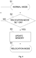
- the refrigeration appliance of the present invention comprises a control unit which includes: a normal mode in which each refrigeration compartment, such as a freezer compartment and a fresh food compartment is refrigerated and a user-selectable relocation mode in which the refrigeration circuit, in particular each evaporator thereof such as a freezer evaporator and a fresh food evaporator is completely defrosted and the melted frost i.e water which has been drained into the evaporator tray is completely evaporated.
- the control unit monitors whether the relocation mode is currently set on or off by the user.
- control unit halts the normal mode and activates the relocation mode. However, if it is determined that the relocation mode is set off then the control unit halts the relocation mode and activates the normal mode.
- the evaporating tray is provided with an auxiliary heater for evaporating the water therein.
- the control unit energizes the auxiliary heater until the water is completely evaporated.
- the auxiliary heater is energized for a predetermined duration which is proven to be sufficient for evaporating the entire water.
- mechanical or electrical sensors are used to detect a remaining water level in the evaporating tray.
- the user is informed that the refrigeration appliance is ready for relocation. Thereafter, the door of each compartment is locked.
- a stepper motor is used to commonly lock the doors of the freezer compartment and the fresh food compartments.
- a freezer fan and/or a fresh food fan are energized to dry the interior of the respective compartments during the relocation mode. Thereby the moisture is initially frozen on the respective evaporator and subsequently melted and drained off to the evaporator tray.
- the refrigeration appliance has a non-volatile memory.
- the non-volatile memory is used to store various type of information.
- the non-volatile memory is used to store a first type of information which indicates whether the relocation mode is currently set on or off.
- the non-volatile memory is also used to store a second type of information which is indicative whether the refrigeration circuit has been completely defrosted and the melted frost in the evaporator tray has been completely evaporated. Thereby, the control unit can easily manage the relocation mode.
- a third type of information indicative of the locking/unlocking of the doors (8, 9) is written into the non-volatile memory.
- the control unit when the use reenergizes the refrigeration appliance and subsequently reenergizes the refrigeration appliance after the relocation, the control unit remains in the relocation mode until the user sets the relocation mode off.
- the above types of information in the non-volatile memory are updated by the control unit in accordance with user inputs.
- control unit of the refrigeration appliance also includes a normal defrost mode in addition to the above mentioned normal mode and the relocation mode.
- any settings for the relocation mode such as the cut_in and cut_out temperatures for the defrost process are different from those of the normal settings used in the normal defrost mode.
- the user interface has means for audible and/or visually informing the user whether the relocation mode is set on, whether refrigeration appliance is ready for relocation, and whether the doors are locked.
- a refrigeration appliance has been provided with a relocation mode which the user can utilize for the purpose of safely transporting the refrigerator during removal.
- the relocation mode When the relocation mode is set on, the refrigeration appliance establishes a state suitable for the transportation thereof.
- the proliferation of microorganisms and formation of bad odors inside the refrigeration appliance can be effectively avoided.
- the doors can be prevented from causing damages for the entire duration of the transportation.
- the lock mechanism By virtue of the lock mechanism, the need of any adhesive tapes or the like which are likely to damage the finish of the refrigeration appliance have been obviated. Thereby, usability and functionality of the refrigeration appliance have been improved.
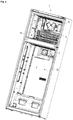
- the refrigeration appliance (1) comprises one or more than one refrigeration compartment (2, 3) for receiving articles to be refrigerated, a refrigeration circuit for refrigerating each refrigeration compartment (2, 3), a defrost circuit for defrosting the refrigeration circuit and for evaporating the melted frost drained into an evaporator tray (4), a user interface (not shown) for inputting a user selection and a control unit (not shown) for controlling the refrigeration circuit, the defrost circuit and the user interface ( Figs. 1 to 3 ).
- the control unit includes a normal mode and a user-selectable relocation mode.
- the user can set the relocation mode on or off via the user interface.
- each refrigeration compartment (2, 3) is refrigerated.
- the relocation mode the refrigeration circuit is completely defrosted and the melted frost which has been drained into the evaporator tray (4) is completely evaporated ( Figs. 4 and 5 ).
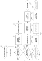
- the method of the present invention for controlling the refrigeration appliance (1) comprises a first step (S2, S14) of monitoring whether the relocation mode is currently set on or off by the user, a step (S4) of halting the normal mode and activating the relocation mode if it is determined in the first monitoring step (S2, S14) that the relocation mode is set on and a step (S1) of halting the relocation mode and activating the normal mode if it is determined in the first monitoring step (S2, S14) that the relocation mode is set off ( Figs. 4 and 5 ).
- the method comprises a step (S3, S15) of writing into a non-volatile memory a first type of information which indicates whether the relocation mode is currently set on or off in accordance with a user input detected in the first monitoring step (S2, S14).
- the first monitoring step (S2, S14) it is also monitored whether the relocation mode is currently set on or off based on the first type of information written into the non-volatile memory ( Figs. 4 and 5 ).
- the refrigeration appliance (1) when the refrigeration appliance (1) is energized, in the first monitoring step (S2, S14) it is immediately monitored whether the relocation mode is currently set on or off based on the first type of information written into the non-volatile memory: if the relocation mode is currently set off then the normal mode is activated, however, if the relocation mode is currently set on then the relocation mode is activated.
- the method comprises: a step (S5, S16) of informing the user via the user interface whether the relocation mode has been activated or deactivated ( Fig. 5 ).
- the method comprises: a second step (S6) of monitoring whether the refrigeration appliance (1) is ready for relocation based on a second type of information written into said non-volatile memory.
- the second type of information written into the non-volatile memory is indicative whether the refrigeration circuit has been completely defrosted and the melted frost in the evaporator tray (4) has been completely evaporated ( Fig. 5 ).
- the step (S4) of activating the relocation mode includes: a step of halting a compressor (13) of the refrigeration circuit, a step (S7) of modifying normal settings for defrosting the refrigeration circuit, wherein the normal settings include cut_in and cut_out temperatures of the defrost circuit, a step (S8) of defrosting the refrigeration circuit in accordance with said modified settings, a step of evaporating the water in the evaporator tray (4) by using an auxiliary heater (4a), a first step (S9a) of determining whether the cut_out temperature according to the modified settings has been reached by using a temperature sensor (5), and a second step (S9b) of determining whether the melted frost in the evaporator tray (4) has been completely evaporated.
- the halting step, the modifying step (S7), the defrosting step (S8), the evaporating step, the first determining step (S9a), and the second determining step (S9) are performed if the second type of information written into the non-volatile memory indicates that the refrigeration appliance is not yet ready for relocation ( Fig. 5 ).
- the cut_in temperature is modified such that the defrost circuit is immediately activated.
- the cut_out temperature is modified such that a complete melting of the frost is ensured.
- the modified cut_out temperature is well above zero degrees centigrade.
- control unit of the refrigeration appliance (1) also includes a normal defrost mode in addition to the above mentioned normal mode and the relocation mode.
- the modified settings for the relocation mode are different from the normal settings used in a normal defrost mode.
- the step (S4) of activating the relocation mode includes: a step of operating a freezer fan (6) and/or fresh food fan (7) during the defrosting step (S8) ( Fig. 5 ). Thereby any residual moisture in the refrigeration compartments (2, 3) can be prevented. Thus, the proliferation of microorganisms and formation of bad odors can be effectively avoided.
- the method comprises: a step (S10) of informing the user via the user interface that the refrigeration appliance (1) is ready for relocation if the results of the first determining step (S9a) and the second determining step (S9b) are both affirmative ( Fig. 5 ).
- the method comprises: a step (S11) of writing into the non-volatile memory a second type of information which indicates whether the refrigeration appliance (1) is ready for relocation based on the results of the first determining step (S9a) and the second determining step (S9b) ( Fig. 5 ).
- the method comprises: a step (S15) of updating the second type of information in the non-volatile memory that the refrigeration appliance (1) is not ready for relocation if the relocation mode is currently set off in accordance with a user input detected in the first monitoring step (S2, S14) ( Fig. 5 ).
- the method comprises: a step (S12) of locking each door (8, 9) of a respective refrigeration compartment (2, 3) by means of a lock mechanism (10) if the refrigeration appliance (1) is ready for relocation and if the relocation mode is currently set on. Thereby, the doors (8, 9) are prevented from opening/closing during the transportation. Hence, the doors (8, 9) are prevented from causing damages.
- the method also comprises: a step (S17) of unlocking each door (8, 9) of a respective refrigeration compartment by means of the lock mechanism (10) if the relocation mode is currently set off by the user ( Fig. 5 ).
- a third information indicative of the locking/unlocking of the doors (8, 9) are also written into the non-volatile memory.
- the third information is also updated each time after a respective change in the state of the doors (8, 9) takes place.
- the method comprises: a step (S13) of suspending operation of the refrigeration appliance (1) after each door (8, 9) of has been locked and if the relocation mode is currently set on.
- the suspending step (S13) i.e., in the suspension state, the defrost process and the refrigeration process are both terminated.
- the refrigeration appliance (1) waits until it is deenergized by the user. Thereafter, the refrigeration appliance (1) can be safely transported, and subsequently energized after installation of the same at its new place ( Fig. 5 ).
- the refrigeration appliance (1) is a domestic refrigerator (1) ( Figs. 1 to 3 ).
- the refrigeration compartments (2, 3) include a freezer compartment (2) and a fresh food compartment (3).
- the freezer compartment (2) and the fresh food compartment (3) are respectively provided with a freezer door (8) and a fresh food door (9) for opening/closing the same.
- the freezer door (8) and the fresh food door (9) are provided with a lock mechanism (10).
- the refrigeration circuit includes: a freezer evaporator (11) arranged to refrigerate the freezer compartment (2), a fresh food evaporator (12) arranged to refrigerate the fresh food compartment (3), a compressor (13), a condenser (14), an expansion valve or the like which are serially connected to circulate a cooling refrigerant.
- the defrost circuit includes, a defrost heater (15), a freezer fan (6) arranged to draw air from the freezer compartment (2) towards the freezer evaporator (11), a fresh food fan (7) arranged to draw air from the fresh food compartment (3) towards the fresh food evaporator (12), an auxiliary heater (4a) arranged to evaporate the melted frost drained off into the evaporating tray (4) and a temperature sensor (5) for sensing a temperature of the surfaces of the freezer evaporator (11) and the fresh food evaporator (12) ( Fig. 1 to 3 ).
- the lock mechanism includes a stepper motor (not shown).
- the lock mechanism is configured to commonly open/close both the freezer door (8) and the fresh food door (9) and is arranged between them ( Fig. 1 ).
- the auxiliary heater (4a) is an electrical resistance (not shown).
- the evaporating tray (4) is provided with a mechanical or electrical sensor such as a buoy, a thermostat or the like for detecting a remaining melted frost level.
- the non-volatile memory (not shown) is flash memory.
- the present invention also provides a program comprising computer-readable codes suitable for causing the refrigeration appliance (1) to execute the method steps of the present invention. Therefore, the control unit of refrigeration appliance (1) includes: a microprocessor or the like for running said program and a computer readable storage medium storing said program. In another embodiment, this storage medium also serves as the above-mentioned non-volatile memory.
- the present invention also provides a computer readable storage medium which stores the program of the present invention.
- a refrigeration appliance (1) has been provided with a relocation mode which the user can utilize for the purpose of relocating.
- the refrigeration appliance (1) establishes a state suitable for transporting it.
- the proliferation of microorganisms and formation of bad odors inside the refrigeration appliance (1) can be effectively avoided.
- the doors (8, 9) can be prevented from causing damages for the entire duration of the transportation.
- the lock mechanism (10) the use of any adhesive tapes or the like which are likely to damage the finish of the refrigeration appliance have been obviated.
Landscapes
- Engineering & Computer Science (AREA)
- Chemical & Material Sciences (AREA)
- Combustion & Propulsion (AREA)
- Physics & Mathematics (AREA)
- Mechanical Engineering (AREA)
- Thermal Sciences (AREA)
- General Engineering & Computer Science (AREA)
- Defrosting Systems (AREA)
Claims (13)
- Ein Verfahren für die Steuerung eines Kühlgerätes (1), und zwar eines Haushaltskühlgerätes (1), umfasst eine oder mehrere Kühlfächer (2; 3) für die Aufnahme von zu kühlenden Gegenständen, einen Kühlkreislauf zum Kühlen von jedem Kühlfach (2;3), einen Auftaukreislauf, zum Abtauen des Kühlkreislaufs und eine Verdampferablage (4), zum Verdampfen des abgelassenen und geschmolzenen Frost, eine Zusatzheizung, die für das Verdampfen des in die Verdampferablage (4) abgelassene Wasser zuständig ist, eine Benutzeroberfläche zum Eingeben einer Benutzerauswahl, eine Steuereinheit für das Steuern des Kühlkreislaufs, Abtaukreislaufs und der Benutzeroberfläche, wobei die Steuereinheit einen Normalmodus zum Kühlen von jedem Kühlfach (2; 3) und eine von dem Benutzer aus wählbare Verlagerungsmodus für das vollständige Abtauen des Kühlkreislaufs und für das vollständige Verdampfen des geschmolzenen Frosts in der Verdampferablage (4) enthält, wobei dieses Verfahren weiterhin folgendes umfasst:- einen ersten Schritt (S2; S14) zum Kontrollieren, ob der Umsetzungsmodus in dem Moment von dem Benutzer aus ein- oder ausgeschaltet wird,- einen Schritt (S4) für das Anhalten des Normalmodus und des Aktivierens des Umsetzungsmodus, wobei der Zusatzheizer durch die Steuereinheit mit Energie versorgt wird, bis das Wasser vollständig verdampft ist, wenn in dem ersten Überwachungsschritt (S2, S14) festgestellt wird, dass der Umsetzungsmodus vorliegt ist und eingestellt ist; und- einen Schritt (S1) zum Anhalten des Verschiebungsmodus und das Aktivieren des Normalmodus, wenn im ersten Überwachungsschritt (S2, S14) ausgewählt wird, dass der Verschiebungsmodus ausgeschaltet ist.
- Das Verfahren, wie in Anspruch 1 aufgeführt, ist durch einen Schritt (S3, S15) gekennzeichnet, der das Schreiben eines ersten informationstyps in einem nichtflüchtigen Speicher aufführt, der anzeigt, ob der Umsetzungsmodus gemäß einer erfassten Benutzereingabe im ersten Überwachungsschritt (S2; S14) ein- oder ausgeschaltet ist, wobei in dem ersten Überwachungsschritt (S2; S14) zugleich auch überwacht wird, ob der Verschiebungsmodus gegenwärtig ein- oder ausgeschaltet ist, basierend auf die erste informationsart, die in dem nichtflüchtigen Speicher aufgeführt.
- Das Verfahren wir in den Ansprüchen 1 oder 2 aufgeführt ist gekennzeichnet durch einen Schritt (S5, S16) gekennzeichnet, der zum informieren des Benutzers über die Benutzeroberfläche eingestellt ist und anzeigt, ob der Verschiebungsmodus aktiviert oder deaktiviert ist.
- Das Verfahren nach einem der Ansprüche von 1 bis 3 ist gekennzeichnet durch einen zweiten Schritt (S6) zum Überwachen, ob das Kühlgerät (1) für die Lagerung bereit ist, basierend auf einen zweiten informationstyp, der in einen nichtflüchtigen Speicher aufgeführt ist, wobei der zweite informationstyp, der in den nichtflüchtigen Speicher geschrieben wird, anzeigt, ob der Kühlkreislaug vollständig aufgetaut worden ist und der geschmolzene Frost in der Verdampferablage (4) vollständig verdampft wurde.
- Das Verfahren gemäß Anspruch 4, ist dadurch gekennzeichnet, dass der Schritt (S4) des Aktivierens des Verschiebungsmodus folgendes umfasst:- einen Schritt für das Anhalten eines Kompressors (13) des Kühlkreislaufs,- einen Schritt (S7) für das Modifizieren normaler Einstellungen zum Abtauen des Kühlkreislaufs, wobei die normalen Einstellungen die Ein- und Abschalttemperaturen des Abtaukreislaufs beinhalten,- einen Schritt (S8) für das Abtauen des Kühlkreislaufs nach den veränderten Einstellungen,- einen Schritt für das Verdampfen der geschmolzenen Abtaue in der Verdampferwanne (4) unter der Verwendung der Zusatzheizung (4a),- einen ersten Schritt (S9a) für die Bestimmung der Abschalttemperatur, ob sie gemäß den geänderten Einstellungen unter Verwendung eines Temperatursensors (5) erreicht wurde; und- einen zweiten Schritt (S9b) für die Bestimmung, ob der geschmolzene Frost in der Verdampferwanne (4) vollständig verdampft wurde, wobei der Anhalteschritt, der Modifizierungsschritt (S7), der Entfrostungsschritt (S8), der Verdampfungsschritt, die erste Bestimmung im Schritt (S9a) sind und der zweite Bestimmungsschritt (S9) ausgeführt wird, wenn der in den nichtflüchtigen Speicher geschriebene zweite Informationstyp angibt, dass das Kühlgerät noch nicht für eine Verlagerung bereit ist.
- Das Verfahren wie in Anspruch 5 aufgeführt ist dadurch gekennzeichnet, dass der Schritt (S4) für das Aktivieren des Umsiedebetriebs einen Schritt des Betreibens eines Gefriergebläses (6) und / oder eines Frischelebensmittelkühlers (7) während des Entfrostungsschritts (S8) besitzt.
- Das Verfahren nach Anspruch 6 ist dadurch gekennzeichnet, dass es darüber hinaus einen Schritt (S10) besitzt, der den Benutzer über die Benutzeroberfläche darüber informiert, dass das Kühlgerät (1) für die Verlagerung bereit ist, wenn die Ergebnisse des ersten Bestimmungsschritts (S9a) und der zweiten Bestimmungsschritts (S9b) vorliegen und beide positiv sind.
- Das Verfahren nach eine der Ansprüche 5 bis 7 ist durch einen Schritt (S11) gekennzeichnet, der das Schreiben einer zweiten Art von Informationen in den nichtflüchtigen Speicher eingibt durchführt, die anzeigt, ob das Kühlgerät (1) basierend dem Umzug bereit ist Ergebnisse des ersten Bestimmungsschrittes (S9a) und des zweiten Bestimmunsschrittes (S9b) bereit ist.
- Das Verfahren nach einem der Ansprüche 4 bis 8 ist gekennzeichnet durch einen Schritt (S15) für das Aktualisieren der zweiten Art von Information in dem nichtflüchtigen Speicher, dass das Kühlgerät (1) nicht für eine Verlagerung bereit ist, wenn der Verschiebungsmodus vorliegt wird, anhand einer Benutzereingabe, die in dem ersten Überwachungsschritt (S2, S14) festgelegt wird.
- Das Verfahren nach einem der Ansprüche von 4 bis 9 ist weiterhin
gekennzeichnet durch:- einen Schritt (S12) zum Verriegeln von jeder Tür (8, 9) eines jeweiligen Kühlfachs (2, 3) mithilfe eines Verriegelungsmechanismus (10), wenn das Kühlgerät (1) für einen Standortwechsel bereit ist und der Standortwechselmodus eingestellt ist; und- einen Schritt (S17) für das Entriegeln jeder Tür (8, 9) eines jeweiligen Kühlfachs mithilfe des Verriegelungsmechanismus (10), wenn der Verschiebemodus in diesem Moment ausgeschaltet ist. - Das Verfahren nach Anspruch 10, ist dadurch gekennzeichnet, dass es darüber hinaus einen Schritt (S13) zum Unterbrechen des Betriebs des Kühlgeräts (1) besitzt, nachdem jede Tür verriegelt wurde und der Verschiebungsmodus in diesem Moment eingeschaltet ist.
- Ein Kühlgerät (1), und zwar ein Haushaltskühlgerät (1) für die Durchführung des Verfahrens nach einem der Ansprüche 1 bis 11, umfasst;- eine oder mehrere Kühlfächer (2; 3) für die Aufnahme von Gegenständen, die gekühlt werden sollen,- einen Kühlkreislauf zum Kühlen von jedem Kühlfach (2, 3),- einen Abtaukreis zum Abtauen des Kühlkreislaufs und zum Verdampfen des in eine Verdampferwanne (4) abgelassenen Wassers,- eine Zusatzheizung, die für das Verdampfen des in die Verdampferwanne (4) abgelassenen Wassers eingerichtet ist,- eine Benutzeroberfläche für die Eingabe einer Benutzerauswahl und- eine Steuereinheit zum Steuern des Kühlkreislaufs, des Abtaukreislaufs und der Benutzeroberfläche,wobei die Steuereinheit einen Normalmodus besitzt, in dem jedes Kühlfach (2, 3) gekühlt wird, einen vom Benutzer wählbaren Umstellungsmodus, in dem der Kühlkreislauf vollständig abgetaut ist und das in die Verdampferablage (4) abgelassene Wasser vollständig verdampft ist; wobei die Steuereinheit so eingestellt ist, den Kühlkreislauf, den Abtaukreislauf und die Benutzeroberfläche gemäß den in einem der Ansprüche 1 bis 11 aufgeführten Verfahrensschritten zu steuern.
- Ein Kühlgerät (1), und zwar ein Haushaltskühlgerät (1) wie in Anspruch 12 aufgeführt, für die Durchführung des Verfahrens nach einem der Ansprüche 1 bis 11, ist dadurch gekennzeichnet:- das mehr als ein Kühlfach (2, 3) ein Gefrierfach (2) und ein Frischkostfach (3) umfasst, wobei jeweils eine Gefriertür (8) und eine Frischkosttür (9) zum Öffnen / Schließen vorgesehen sind, wobei die Gefriertür (8) und die Frischkosttür (9) mit einem Verriegelungsmechanismus (10) versehen sind,- der Kühlkreislauf umfasst einen Gefrierfachverdampfer (11) zum Kühlen des Gefrierfachs (2), einen Frischkostverdampfer (12), der zum Kühlen des Frischkostfachs (3) angeordnet ist, einen Kompressor (13), einen Kondensator (14) und ein Expansionsventil oder ähnlichen, die in Reihe geschaltet sind, um ein Kühlkältemittel zu zirkulieren; und- weiterhin umfasst der Abtaukreislauf eine Abtauheizung (15), ein Gefrierfachgebläse (6), das zum Ansaugen von Luft aus dem Gefrierfach (2) in Richtung des Gefrierfachverdampfers (11) angeordnet ist, ein Frischelebensmittelkühlers (7), um Luft aus dem Frischkostfach(3) abzuziehen, in Richtung des Frischverdampfers (12) und einen Temperatursensor (5) zum Erfassen einer Temperatur der Oberflächen des Gefrierfachverdampfer (11) und des Frischkostverdampfers (12).
Applications Claiming Priority (1)
| Application Number | Priority Date | Filing Date | Title |
|---|---|---|---|
| PCT/EP2013/078157 WO2015101401A1 (en) | 2013-12-30 | 2013-12-30 | Refrigeration appliance having a relocation mode and method for controlling the same |
Publications (3)
| Publication Number | Publication Date |
|---|---|
| EP3090224A1 EP3090224A1 (de) | 2016-11-09 |
| EP3090224B1 true EP3090224B1 (de) | 2019-06-12 |
| EP3090224B8 EP3090224B8 (de) | 2019-09-11 |
Family
ID=49911541
Family Applications (1)
| Application Number | Title | Priority Date | Filing Date |
|---|---|---|---|
| EP13815535.3A Not-in-force EP3090224B8 (de) | 2013-12-30 | 2013-12-30 | Kältevorrichtung mit einem verlagerungsmodus und verfahren zur steuerung davon |
Country Status (2)
| Country | Link |
|---|---|
| EP (1) | EP3090224B8 (de) |
| WO (1) | WO2015101401A1 (de) |
Families Citing this family (1)
| Publication number | Priority date | Publication date | Assignee | Title |
|---|---|---|---|---|
| US10465960B2 (en) | 2016-11-23 | 2019-11-05 | Carrier Corporation | Method and system for monitoring refrigeration system |
Family Cites Families (4)
| Publication number | Priority date | Publication date | Assignee | Title |
|---|---|---|---|---|
| JP2902909B2 (ja) * | 1993-06-30 | 1999-06-07 | 三洋電機株式会社 | 除霜装置 |
| DE20306747U1 (de) * | 2003-04-30 | 2003-06-26 | Dometic S.A.R.L., Hosingen | Kühlsystem |
| US20080092569A1 (en) * | 2006-10-20 | 2008-04-24 | Doberstein Andrew J | Cooling unit with multi-parameter defrost control |
| JP2013104606A (ja) * | 2011-11-14 | 2013-05-30 | Panasonic Corp | 冷凍サイクル装置及び温水生成装置 |
-
2013
- 2013-12-30 WO PCT/EP2013/078157 patent/WO2015101401A1/en not_active Ceased
- 2013-12-30 EP EP13815535.3A patent/EP3090224B8/de not_active Not-in-force
Non-Patent Citations (1)
| Title |
|---|
| None * |
Also Published As
| Publication number | Publication date |
|---|---|
| EP3090224A1 (de) | 2016-11-09 |
| WO2015101401A1 (en) | 2015-07-09 |
| EP3090224B8 (de) | 2019-09-11 |
Similar Documents
| Publication | Publication Date | Title |
|---|---|---|
| US9772138B2 (en) | Cooling box | |
| JP5260416B2 (ja) | 冷蔵庫 | |
| WO2012014374A1 (ja) | 冷凍装置 | |
| CN108291763A (zh) | 低环境温度条件下的制冷腔的温度控制 | |
| KR101668302B1 (ko) | 냉장고 | |
| US7089752B2 (en) | Refrigerator and defrosting method thereof | |
| JP2013113562A (ja) | 車両用冷却装置 | |
| JP5393283B2 (ja) | 冷蔵庫 | |
| JP2011002228A (ja) | 冷蔵庫 | |
| JP6270375B2 (ja) | 冷蔵庫 | |
| EP3090224B1 (de) | Kältevorrichtung mit einem verlagerungsmodus und verfahren zur steuerung davon | |
| KR101698101B1 (ko) | 냉장고 및 이의 제어방법 | |
| JP2008075964A (ja) | 冷却装置の除霜装置 | |
| JP5975379B2 (ja) | 冷却貯蔵庫 | |
| JP5931606B2 (ja) | 冷蔵庫 | |
| CN100533015C (zh) | 冰箱 | |
| JP2014095530A (ja) | 冷蔵庫 | |
| JP2017020745A (ja) | 冷却貯蔵庫 | |
| JP2009127881A (ja) | 冷蔵庫 | |
| KR100219430B1 (ko) | 냉장고의 과냉 방지방법 | |
| JP2022186118A (ja) | 冷却貯蔵庫 | |
| JP7614021B2 (ja) | 冷却貯蔵庫 | |
| JP2002267295A (ja) | 冷蔵庫 | |
| KR20160095278A (ko) | 냉장고 제상 운전 방법 | |
| JPH0942809A (ja) | 低温庫 |
Legal Events
| Date | Code | Title | Description |
|---|---|---|---|
| PUAI | Public reference made under article 153(3) epc to a published international application that has entered the european phase |
Free format text: ORIGINAL CODE: 0009012 |
|
| 17P | Request for examination filed |
Effective date: 20160722 |
|
| AK | Designated contracting states |
Kind code of ref document: A1 Designated state(s): AL AT BE BG CH CY CZ DE DK EE ES FI FR GB GR HR HU IE IS IT LI LT LU LV MC MK MT NL NO PL PT RO RS SE SI SK SM TR |
|
| AX | Request for extension of the european patent |
Extension state: BA ME |
|
| DAX | Request for extension of the european patent (deleted) | ||
| STAA | Information on the status of an ep patent application or granted ep patent |
Free format text: STATUS: EXAMINATION IS IN PROGRESS |
|
| 17Q | First examination report despatched |
Effective date: 20180613 |
|
| GRAP | Despatch of communication of intention to grant a patent |
Free format text: ORIGINAL CODE: EPIDOSNIGR1 |
|
| STAA | Information on the status of an ep patent application or granted ep patent |
Free format text: STATUS: GRANT OF PATENT IS INTENDED |
|
| INTG | Intention to grant announced |
Effective date: 20190305 |
|
| GRAS | Grant fee paid |
Free format text: ORIGINAL CODE: EPIDOSNIGR3 |
|
| GRAA | (expected) grant |
Free format text: ORIGINAL CODE: 0009210 |
|
| STAA | Information on the status of an ep patent application or granted ep patent |
Free format text: STATUS: THE PATENT HAS BEEN GRANTED |
|
| AK | Designated contracting states |
Kind code of ref document: B1 Designated state(s): AL AT BE BG CH CY CZ DE DK EE ES FI FR GB GR HR HU IE IS IT LI LT LU LV MC MK MT NL NO PL PT RO RS SE SI SK SM TR |
|
| REG | Reference to a national code |
Ref country code: GB Ref legal event code: FG4D |
|
| REG | Reference to a national code |
Ref country code: CH Ref legal event code: EP |
|
| REG | Reference to a national code |
Ref country code: AT Ref legal event code: REF Ref document number: 1143089 Country of ref document: AT Kind code of ref document: T Effective date: 20190615 |
|
| RAP2 | Party data changed (patent owner data changed or rights of a patent transferred) |
Owner name: ARCELIK ANONIM SIRKETI |
|
| REG | Reference to a national code |
Ref country code: DE Ref legal event code: R096 Ref document number: 602013056604 Country of ref document: DE |
|
| REG | Reference to a national code |
Ref country code: IE Ref legal event code: FG4D |
|
| REG | Reference to a national code |
Ref country code: CH Ref legal event code: PK Free format text: BERICHTIGUNG B8 |
|
| REG | Reference to a national code |
Ref country code: NL Ref legal event code: MP Effective date: 20190612 |
|
| REG | Reference to a national code |
Ref country code: LT Ref legal event code: MG4D |
|
| PG25 | Lapsed in a contracting state [announced via postgrant information from national office to epo] |
Ref country code: HR Free format text: LAPSE BECAUSE OF FAILURE TO SUBMIT A TRANSLATION OF THE DESCRIPTION OR TO PAY THE FEE WITHIN THE PRESCRIBED TIME-LIMIT Effective date: 20190612 Ref country code: NO Free format text: LAPSE BECAUSE OF FAILURE TO SUBMIT A TRANSLATION OF THE DESCRIPTION OR TO PAY THE FEE WITHIN THE PRESCRIBED TIME-LIMIT Effective date: 20190912 Ref country code: SE Free format text: LAPSE BECAUSE OF FAILURE TO SUBMIT A TRANSLATION OF THE DESCRIPTION OR TO PAY THE FEE WITHIN THE PRESCRIBED TIME-LIMIT Effective date: 20190612 Ref country code: FI Free format text: LAPSE BECAUSE OF FAILURE TO SUBMIT A TRANSLATION OF THE DESCRIPTION OR TO PAY THE FEE WITHIN THE PRESCRIBED TIME-LIMIT Effective date: 20190612 Ref country code: AL Free format text: LAPSE BECAUSE OF FAILURE TO SUBMIT A TRANSLATION OF THE DESCRIPTION OR TO PAY THE FEE WITHIN THE PRESCRIBED TIME-LIMIT Effective date: 20190612 Ref country code: LT Free format text: LAPSE BECAUSE OF FAILURE TO SUBMIT A TRANSLATION OF THE DESCRIPTION OR TO PAY THE FEE WITHIN THE PRESCRIBED TIME-LIMIT Effective date: 20190612 |
|
| PG25 | Lapsed in a contracting state [announced via postgrant information from national office to epo] |
Ref country code: BG Free format text: LAPSE BECAUSE OF FAILURE TO SUBMIT A TRANSLATION OF THE DESCRIPTION OR TO PAY THE FEE WITHIN THE PRESCRIBED TIME-LIMIT Effective date: 20190912 Ref country code: RS Free format text: LAPSE BECAUSE OF FAILURE TO SUBMIT A TRANSLATION OF THE DESCRIPTION OR TO PAY THE FEE WITHIN THE PRESCRIBED TIME-LIMIT Effective date: 20190612 Ref country code: GR Free format text: LAPSE BECAUSE OF FAILURE TO SUBMIT A TRANSLATION OF THE DESCRIPTION OR TO PAY THE FEE WITHIN THE PRESCRIBED TIME-LIMIT Effective date: 20190913 Ref country code: LV Free format text: LAPSE BECAUSE OF FAILURE TO SUBMIT A TRANSLATION OF THE DESCRIPTION OR TO PAY THE FEE WITHIN THE PRESCRIBED TIME-LIMIT Effective date: 20190612 |
|
| REG | Reference to a national code |
Ref country code: AT Ref legal event code: MK05 Ref document number: 1143089 Country of ref document: AT Kind code of ref document: T Effective date: 20190612 |
|
| PG25 | Lapsed in a contracting state [announced via postgrant information from national office to epo] |
Ref country code: SK Free format text: LAPSE BECAUSE OF FAILURE TO SUBMIT A TRANSLATION OF THE DESCRIPTION OR TO PAY THE FEE WITHIN THE PRESCRIBED TIME-LIMIT Effective date: 20190612 Ref country code: RO Free format text: LAPSE BECAUSE OF FAILURE TO SUBMIT A TRANSLATION OF THE DESCRIPTION OR TO PAY THE FEE WITHIN THE PRESCRIBED TIME-LIMIT Effective date: 20190612 Ref country code: CZ Free format text: LAPSE BECAUSE OF FAILURE TO SUBMIT A TRANSLATION OF THE DESCRIPTION OR TO PAY THE FEE WITHIN THE PRESCRIBED TIME-LIMIT Effective date: 20190612 Ref country code: AT Free format text: LAPSE BECAUSE OF FAILURE TO SUBMIT A TRANSLATION OF THE DESCRIPTION OR TO PAY THE FEE WITHIN THE PRESCRIBED TIME-LIMIT Effective date: 20190612 Ref country code: EE Free format text: LAPSE BECAUSE OF FAILURE TO SUBMIT A TRANSLATION OF THE DESCRIPTION OR TO PAY THE FEE WITHIN THE PRESCRIBED TIME-LIMIT Effective date: 20190612 Ref country code: NL Free format text: LAPSE BECAUSE OF FAILURE TO SUBMIT A TRANSLATION OF THE DESCRIPTION OR TO PAY THE FEE WITHIN THE PRESCRIBED TIME-LIMIT Effective date: 20190612 Ref country code: PT Free format text: LAPSE BECAUSE OF FAILURE TO SUBMIT A TRANSLATION OF THE DESCRIPTION OR TO PAY THE FEE WITHIN THE PRESCRIBED TIME-LIMIT Effective date: 20191014 |
|
| PG25 | Lapsed in a contracting state [announced via postgrant information from national office to epo] |
Ref country code: SM Free format text: LAPSE BECAUSE OF FAILURE TO SUBMIT A TRANSLATION OF THE DESCRIPTION OR TO PAY THE FEE WITHIN THE PRESCRIBED TIME-LIMIT Effective date: 20190612 Ref country code: IS Free format text: LAPSE BECAUSE OF FAILURE TO SUBMIT A TRANSLATION OF THE DESCRIPTION OR TO PAY THE FEE WITHIN THE PRESCRIBED TIME-LIMIT Effective date: 20191012 Ref country code: IT Free format text: LAPSE BECAUSE OF FAILURE TO SUBMIT A TRANSLATION OF THE DESCRIPTION OR TO PAY THE FEE WITHIN THE PRESCRIBED TIME-LIMIT Effective date: 20190612 Ref country code: ES Free format text: LAPSE BECAUSE OF FAILURE TO SUBMIT A TRANSLATION OF THE DESCRIPTION OR TO PAY THE FEE WITHIN THE PRESCRIBED TIME-LIMIT Effective date: 20190612 |
|
| REG | Reference to a national code |
Ref country code: DE Ref legal event code: R097 Ref document number: 602013056604 Country of ref document: DE |
|
| PLBE | No opposition filed within time limit |
Free format text: ORIGINAL CODE: 0009261 |
|
| STAA | Information on the status of an ep patent application or granted ep patent |
Free format text: STATUS: NO OPPOSITION FILED WITHIN TIME LIMIT |
|
| PG25 | Lapsed in a contracting state [announced via postgrant information from national office to epo] |
Ref country code: PL Free format text: LAPSE BECAUSE OF FAILURE TO SUBMIT A TRANSLATION OF THE DESCRIPTION OR TO PAY THE FEE WITHIN THE PRESCRIBED TIME-LIMIT Effective date: 20190612 Ref country code: DK Free format text: LAPSE BECAUSE OF FAILURE TO SUBMIT A TRANSLATION OF THE DESCRIPTION OR TO PAY THE FEE WITHIN THE PRESCRIBED TIME-LIMIT Effective date: 20190612 |
|
| 26N | No opposition filed |
Effective date: 20200313 |
|
| PG25 | Lapsed in a contracting state [announced via postgrant information from national office to epo] |
Ref country code: IS Free format text: LAPSE BECAUSE OF FAILURE TO SUBMIT A TRANSLATION OF THE DESCRIPTION OR TO PAY THE FEE WITHIN THE PRESCRIBED TIME-LIMIT Effective date: 20200224 Ref country code: SI Free format text: LAPSE BECAUSE OF FAILURE TO SUBMIT A TRANSLATION OF THE DESCRIPTION OR TO PAY THE FEE WITHIN THE PRESCRIBED TIME-LIMIT Effective date: 20190612 |
|
| REG | Reference to a national code |
Ref country code: DE Ref legal event code: R119 Ref document number: 602013056604 Country of ref document: DE |
|
| PG2D | Information on lapse in contracting state deleted |
Ref country code: IS |
|
| REG | Reference to a national code |
Ref country code: CH Ref legal event code: PL |
|
| REG | Reference to a national code |
Ref country code: BE Ref legal event code: MM Effective date: 20191231 |
|
| PG25 | Lapsed in a contracting state [announced via postgrant information from national office to epo] |
Ref country code: MC Free format text: LAPSE BECAUSE OF FAILURE TO SUBMIT A TRANSLATION OF THE DESCRIPTION OR TO PAY THE FEE WITHIN THE PRESCRIBED TIME-LIMIT Effective date: 20190612 |
|
| GBPC | Gb: european patent ceased through non-payment of renewal fee |
Effective date: 20191230 |
|
| PG25 | Lapsed in a contracting state [announced via postgrant information from national office to epo] |
Ref country code: DE Free format text: LAPSE BECAUSE OF NON-PAYMENT OF DUE FEES Effective date: 20200701 Ref country code: GB Free format text: LAPSE BECAUSE OF NON-PAYMENT OF DUE FEES Effective date: 20191230 Ref country code: LU Free format text: LAPSE BECAUSE OF NON-PAYMENT OF DUE FEES Effective date: 20191230 Ref country code: IE Free format text: LAPSE BECAUSE OF NON-PAYMENT OF DUE FEES Effective date: 20191230 Ref country code: FR Free format text: LAPSE BECAUSE OF NON-PAYMENT OF DUE FEES Effective date: 20191231 |
|
| PG25 | Lapsed in a contracting state [announced via postgrant information from national office to epo] |
Ref country code: CH Free format text: LAPSE BECAUSE OF NON-PAYMENT OF DUE FEES Effective date: 20191231 Ref country code: LI Free format text: LAPSE BECAUSE OF NON-PAYMENT OF DUE FEES Effective date: 20191231 Ref country code: BE Free format text: LAPSE BECAUSE OF NON-PAYMENT OF DUE FEES Effective date: 20191231 |
|
| PG25 | Lapsed in a contracting state [announced via postgrant information from national office to epo] |
Ref country code: CY Free format text: LAPSE BECAUSE OF FAILURE TO SUBMIT A TRANSLATION OF THE DESCRIPTION OR TO PAY THE FEE WITHIN THE PRESCRIBED TIME-LIMIT Effective date: 20190612 |
|
| PG25 | Lapsed in a contracting state [announced via postgrant information from national office to epo] |
Ref country code: HU Free format text: LAPSE BECAUSE OF FAILURE TO SUBMIT A TRANSLATION OF THE DESCRIPTION OR TO PAY THE FEE WITHIN THE PRESCRIBED TIME-LIMIT; INVALID AB INITIO Effective date: 20131230 Ref country code: MT Free format text: LAPSE BECAUSE OF FAILURE TO SUBMIT A TRANSLATION OF THE DESCRIPTION OR TO PAY THE FEE WITHIN THE PRESCRIBED TIME-LIMIT Effective date: 20190612 |
|
| PG25 | Lapsed in a contracting state [announced via postgrant information from national office to epo] |
Ref country code: MK Free format text: LAPSE BECAUSE OF FAILURE TO SUBMIT A TRANSLATION OF THE DESCRIPTION OR TO PAY THE FEE WITHIN THE PRESCRIBED TIME-LIMIT Effective date: 20190612 |
|
| PG25 | Lapsed in a contracting state [announced via postgrant information from national office to epo] |
Ref country code: TR Free format text: LAPSE BECAUSE OF NON-PAYMENT OF DUE FEES Effective date: 20191230 |