EP3083327B1 - Pièce en mousse, en particulier pour un siège de véhicule et siège de véhicule - Google Patents
Pièce en mousse, en particulier pour un siège de véhicule et siège de véhicule Download PDFInfo
- Publication number
- EP3083327B1 EP3083327B1 EP14811929.0A EP14811929A EP3083327B1 EP 3083327 B1 EP3083327 B1 EP 3083327B1 EP 14811929 A EP14811929 A EP 14811929A EP 3083327 B1 EP3083327 B1 EP 3083327B1
- Authority
- EP
- European Patent Office
- Prior art keywords
- foam
- comfort
- foam part
- holes
- blind hole
- Prior art date
- Legal status (The legal status is an assumption and is not a legal conclusion. Google has not performed a legal analysis and makes no representation as to the accuracy of the status listed.)
- Active
Links
Images


Classifications
-
- B—PERFORMING OPERATIONS; TRANSPORTING
- B60—VEHICLES IN GENERAL
- B60N—SEATS SPECIALLY ADAPTED FOR VEHICLES; VEHICLE PASSENGER ACCOMMODATION NOT OTHERWISE PROVIDED FOR
- B60N2/00—Seats specially adapted for vehicles; Arrangement or mounting of seats in vehicles
- B60N2/56—Heating or ventilating devices
- B60N2/5607—Heating or ventilating devices characterised by convection
- B60N2/5621—Heating or ventilating devices characterised by convection by air
- B60N2/5664—Heating or ventilating devices characterised by convection by air with unforced air circulation, i.e. not using a fan or the like
-
- B—PERFORMING OPERATIONS; TRANSPORTING
- B60—VEHICLES IN GENERAL
- B60N—SEATS SPECIALLY ADAPTED FOR VEHICLES; VEHICLE PASSENGER ACCOMMODATION NOT OTHERWISE PROVIDED FOR
- B60N2/00—Seats specially adapted for vehicles; Arrangement or mounting of seats in vehicles
- B60N2/70—Upholstery springs ; Upholstery
- B60N2/7017—Upholstery springs ; Upholstery characterised by the manufacturing process; manufacturing upholstery or upholstery springs not otherwise provided for
-
- B—PERFORMING OPERATIONS; TRANSPORTING
- B29—WORKING OF PLASTICS; WORKING OF SUBSTANCES IN A PLASTIC STATE IN GENERAL
- B29C—SHAPING OR JOINING OF PLASTICS; SHAPING OF MATERIAL IN A PLASTIC STATE, NOT OTHERWISE PROVIDED FOR; AFTER-TREATMENT OF THE SHAPED PRODUCTS, e.g. REPAIRING
- B29C44/00—Shaping by internal pressure generated in the material, e.g. swelling or foaming ; Producing porous or cellular expanded plastics articles
- B29C44/02—Shaping by internal pressure generated in the material, e.g. swelling or foaming ; Producing porous or cellular expanded plastics articles for articles of definite length, i.e. discrete articles
- B29C44/04—Shaping by internal pressure generated in the material, e.g. swelling or foaming ; Producing porous or cellular expanded plastics articles for articles of definite length, i.e. discrete articles consisting of at least two parts of chemically or physically different materials, e.g. having different densities
- B29C44/0461—Shaping by internal pressure generated in the material, e.g. swelling or foaming ; Producing porous or cellular expanded plastics articles for articles of definite length, i.e. discrete articles consisting of at least two parts of chemically or physically different materials, e.g. having different densities by having different chemical compositions in different places, e.g. having different concentrations of foaming agent, feeding one composition after the other
- B29C44/0476—Shaping by internal pressure generated in the material, e.g. swelling or foaming ; Producing porous or cellular expanded plastics articles for articles of definite length, i.e. discrete articles consisting of at least two parts of chemically or physically different materials, e.g. having different densities by having different chemical compositions in different places, e.g. having different concentrations of foaming agent, feeding one composition after the other by pouring more than one composition into an open mould
-
- B—PERFORMING OPERATIONS; TRANSPORTING
- B29—WORKING OF PLASTICS; WORKING OF SUBSTANCES IN A PLASTIC STATE IN GENERAL
- B29C—SHAPING OR JOINING OF PLASTICS; SHAPING OF MATERIAL IN A PLASTIC STATE, NOT OTHERWISE PROVIDED FOR; AFTER-TREATMENT OF THE SHAPED PRODUCTS, e.g. REPAIRING
- B29C44/00—Shaping by internal pressure generated in the material, e.g. swelling or foaming ; Producing porous or cellular expanded plastics articles
- B29C44/02—Shaping by internal pressure generated in the material, e.g. swelling or foaming ; Producing porous or cellular expanded plastics articles for articles of definite length, i.e. discrete articles
- B29C44/04—Shaping by internal pressure generated in the material, e.g. swelling or foaming ; Producing porous or cellular expanded plastics articles for articles of definite length, i.e. discrete articles consisting of at least two parts of chemically or physically different materials, e.g. having different densities
- B29C44/06—Making multilayered articles
-
- B—PERFORMING OPERATIONS; TRANSPORTING
- B60—VEHICLES IN GENERAL
- B60N—SEATS SPECIALLY ADAPTED FOR VEHICLES; VEHICLE PASSENGER ACCOMMODATION NOT OTHERWISE PROVIDED FOR
- B60N2/00—Seats specially adapted for vehicles; Arrangement or mounting of seats in vehicles
- B60N2/24—Seats specially adapted for vehicles; Arrangement or mounting of seats in vehicles for particular purposes or particular vehicles
- B60N2/42—Seats specially adapted for vehicles; Arrangement or mounting of seats in vehicles for particular purposes or particular vehicles the seat constructed to protect the occupant from the effect of abnormal g-forces, e.g. crash or safety seats
- B60N2/427—Seats or parts thereof displaced during a crash
- B60N2/42709—Seats or parts thereof displaced during a crash involving residual deformation or fracture of the structure
- B60N2/42718—Seats or parts thereof displaced during a crash involving residual deformation or fracture of the structure with anti-submarining systems
-
- B—PERFORMING OPERATIONS; TRANSPORTING
- B60—VEHICLES IN GENERAL
- B60N—SEATS SPECIALLY ADAPTED FOR VEHICLES; VEHICLE PASSENGER ACCOMMODATION NOT OTHERWISE PROVIDED FOR
- B60N2/00—Seats specially adapted for vehicles; Arrangement or mounting of seats in vehicles
- B60N2/70—Upholstery springs ; Upholstery
-
- B—PERFORMING OPERATIONS; TRANSPORTING
- B60—VEHICLES IN GENERAL
- B60N—SEATS SPECIALLY ADAPTED FOR VEHICLES; VEHICLE PASSENGER ACCOMMODATION NOT OTHERWISE PROVIDED FOR
- B60N2/00—Seats specially adapted for vehicles; Arrangement or mounting of seats in vehicles
- B60N2/90—Details or parts not otherwise provided for
-
- B—PERFORMING OPERATIONS; TRANSPORTING
- B29—WORKING OF PLASTICS; WORKING OF SUBSTANCES IN A PLASTIC STATE IN GENERAL
- B29K—INDEXING SCHEME ASSOCIATED WITH SUBCLASSES B29B, B29C OR B29D, RELATING TO MOULDING MATERIALS OR TO MATERIALS FOR MOULDS, REINFORCEMENTS, FILLERS OR PREFORMED PARTS, e.g. INSERTS
- B29K2075/00—Use of PU, i.e. polyureas or polyurethanes or derivatives thereof, as moulding material
-
- B—PERFORMING OPERATIONS; TRANSPORTING
- B29—WORKING OF PLASTICS; WORKING OF SUBSTANCES IN A PLASTIC STATE IN GENERAL
- B29K—INDEXING SCHEME ASSOCIATED WITH SUBCLASSES B29B, B29C OR B29D, RELATING TO MOULDING MATERIALS OR TO MATERIALS FOR MOULDS, REINFORCEMENTS, FILLERS OR PREFORMED PARTS, e.g. INSERTS
- B29K2105/00—Condition, form or state of moulded material or of the material to be shaped
- B29K2105/04—Condition, form or state of moulded material or of the material to be shaped cellular or porous
-
- B—PERFORMING OPERATIONS; TRANSPORTING
- B29—WORKING OF PLASTICS; WORKING OF SUBSTANCES IN A PLASTIC STATE IN GENERAL
- B29L—INDEXING SCHEME ASSOCIATED WITH SUBCLASS B29C, RELATING TO PARTICULAR ARTICLES
- B29L2031/00—Other particular articles
- B29L2031/58—Upholstery or cushions, e.g. vehicle upholstery or interior padding
-
- B—PERFORMING OPERATIONS; TRANSPORTING
- B29—WORKING OF PLASTICS; WORKING OF SUBSTANCES IN A PLASTIC STATE IN GENERAL
- B29L—INDEXING SCHEME ASSOCIATED WITH SUBCLASS B29C, RELATING TO PARTICULAR ARTICLES
- B29L2031/00—Other particular articles
- B29L2031/771—Seats
Definitions
- the invention relates to a foam part, in particular for a vehicle seat, with a plurality of comfort tubes facing a user, wherein a plurality of the comfort tubes each have one or more holes.
- the invention also relates to a vehicle seat having such a foam part.
- foam parts for vehicle seats which serve a cushioning of the seat structure and the user of the vehicle seat to provide the best possible seating comfort.
- Most of the seat upholstery comprises a foam part for the seat cushion and a separate foam part for the seat back.
- Each of the two foam parts has a central region and two side cheeks.
- the central portion of the foam member supports the buttocks and the thigh backs of the occupant of the vehicle seat down, while the two side cheeks abut each side of a thigh and thereby can absorb lateral forces on the occupant, especially during cornering.
- the central region of the foam part supports the back of the occupant to the rear, while the two side cheeks abut the side of the back and thereby can absorb lateral forces on the occupant.
- Out DE 202 02 042 U1 is a foam part, in particular for a vehicle seat, with a user facing first foam layer and a user facing away from the second foam layer known, wherein the first foam layer with respect to the second foam layer different hardness and / or density.
- the foam part has several holes in the middle seat.
- the DE 20 2007 002 196 U1 discloses a foam part, in particular for a vehicle seat, with a first foam layer facing a user and a second foam layer facing away from the user and an intermediate layer arranged between the foam layers. To improve the moisture transport properties, the foam part has a system of holes.
- the EP 1 068 094 B1 discloses a foam member having a plurality of integrally formed on a base body of the foam member, adjacent, and substantially perpendicular to the seat surface of the body away upwardly extending, referred to as tube sections comfort tubes for comfort.
- the comfort tubes are first compressed, while the base body is only slightly deformed. Only after significant deformation of the comfort tubes of the main body is compressed more. As a result, a two-stage Einsitz is achieved with increasing pad hardness.
- the comfort tubes have holes completely through the foam part.
- a foam part with a plurality of blind holes which extend from a substantially flat foam part surface in a substantially perpendicular direction to the foam part surface in the foam part inside.
- the GB 2 441 417 A discloses a foam member for a vehicle seat having a foam facing surface facing an occupant, the foam member surface having a plurality of holes formed as a blind hole, the blind holes extending from an occupant facing surface of the foam member.
- a foam part is known, consisting of a first Schauteil Mrs arranged above and a second foam layer arranged below the first foam layer.
- the first foam sub-layer has an occupant-facing foam part surface.
- the occupant facing foam part surface has a plurality of continuous ventilation holes.
- the WO 2007/128113 A1 discloses a foamed mattress.
- the mattress is flat and therefore not suitable for a vehicle seat.
- the mattress has a foam base which is connected to a body contact mat.
- the body contact mat faces a human body resting on the mattress.
- the foam base has several comfort tubes, each having a hole. The holes connect a surface of the body contact mat, each with an inner cavity.
- a cushion support in the form of a foamed mattress or a foamed cushion is known.
- the cushion support is largely flat and not suitable for a vehicle seat.
- the cushion support has a plurality of blind holes, which are remote from a resting on the mattress human body.
- the blind holes originate from a side of the padding carrier facing away from the human body.
- Two-zone foams are known from the prior art, in which the central region is made softer than the side cheeks by using different foam materials.
- the side support for the user increases the comfort and on the other hand, the side support for the user to be improved.
- These are often used cut foam pads in the middle and hard foam insert in the side walls.
- an anti-submarining function is frequently provided by an additional component made of a particle foam material, for example EPP (expanded polypropylene).
- EPP expanded polypropylene
- a foam part comprising a first region of foam of a first composition and a second region of foam of a second composition, wherein between the first and the second region a network of polyethylene, jute, gauze non-woven or the like is arranged.
- this foam part does not meet the highest comfort requirements during seating, especially not when initially a very soft cushion layer is desired during seating.
- a comparable upholstery is also from the WO 2010/102785 A2 known.
- the invention is based on the object to improve a foam part of the type mentioned.
- the seating comfort of the occupant should be increased.
- the resilience of the pad surface should be specifically adaptable, for example, an influence of a arranged below the foam member seat structure can be compensated for the flexibility of the foam part and a targeted air distribution for a seat air conditioning.
- a vehicle seat is to be provided with such a foam part available.
- comfort tube is to be understood as meaning an elevated area of the foam facing the occupant, which may have very different geometries.
- the comfort tubes form in the occupant facing cushion areas largely freestanding, in particular completely freestanding elevations relative to a main body of the foam part.
- the comfort tubes are completely or largely surrounded by a depression.
- the recess may be about 5 mm to 50 mm deep, preferably 10 mm to 25 mm deep, and most preferably 15 mm to 20 mm deep.
- the depth of the depression corresponds to the height of the adjacent comfort tube.
- the comfort tubes may be formed hollow inside, for example, for purposes of seat conditioning, or made of solid material.
- through holes or blind holes may pass through the comfort tubes and a basic body of the foam part carrying the comfort tubes.
- a comfort tube none, one or more, in particular two, mutually offset, in particular parallel holes have.
- the non-blind through holes extend completely through the foam member so that air can flow from the bottom of the foam member through the holes to the top of the foam member and vice versa.
- the holes are cylindrical, in particular circular cylindrical.
- the holes can be produced by simple means.
- any other cross sections of the holes are also possible.
- the compliance of a single comfort tube can also be selectively influenced by the provision of multiple holes and / or a combination of blind holes and through holes.
- comfort tubes with several holes in the region of the seat center, viewed in the vehicle transverse direction, arranged.
- the outer contours of the cross sections of the comfort tubes can in principle have all known cross sections of solid bodies and in particular round, polygonal, honeycomb or as in the EP 1 068 094 B1 described, be executed.
- the outer contours of the comfort tubes are independent of the cross sections of the holes, so that, for example, a square comfort tube can have an oval hole.
- At least one comfort tube can have exactly one blind hole.
- a plurality of comfort tubes can have exactly one blind hole.
- a comfort tube can also have several blind holes. This is useful if the dimension of the comfort tube is greater by a multiple in at least one direction perpendicular to the blind hole, than the diameter of the blind hole.
- At least one comfort tube may have a blind hole and a through hole. This is useful if an asymmetrical compliance behavior of a comfort tube is desired.
- a blind hole starts from an occupant-facing surface of the foam part.
- a blind hole can also emanate from a surface of the foam part facing away from an occupant.
- a blind hole preferably runs approximately in the direction perpendicular to the surface of the foam part.
- a blind hole preferably runs parallel to a closing direction of a tool having a lower part and an upper part for producing the foam part. The lower part and the upper part form a cavity of the tool, in which the Schauteil is foamed.
- the closing direction is the direction in which the upper part moves relative to the lower part when opening and closing the tool.
- a blind hole may deviate from an exactly perpendicular direction to the surface of the foam part, which is described by the feature approximately perpendicular.
- approximately perpendicular means that the course of the blind hole is parallel to the closing direction of the tool and / or perpendicular to a surface of the foam part and / or perpendicular to a partial surface of the foam part and / or perpendicular to a surface of the comfort tube.
- angle deviations include up to 15 ° from one of the stated perpendiculars or the closing direction.
- a partial surface of the foam part may be, for example, the surface of a central region of a seat surface.
- a blind hole may extend in a vertical or approximately perpendicular direction to the occupant-oriented surface of a comfort tube.
- a blind hole may extend in a vertical or approximately perpendicular direction to a level of compensation of a surface of a comfort tube or portion of the occupant-oriented surface.
- the depth of a blind hole may correspond to the height of the associated comfort tube. However, the depth of the blind hole may also be less than the height of the associated comfort tube or greater than the height of the associated comfort tube. Under assigned comfort tube is the comfort tube to understand in which the blind hole extends at least in sections.
- One Blind hole may be about 5 mm to 100 mm deep, preferably 20 mm to 80 mm deep and most preferably 40 mm to 60 mm deep.
- Several blind holes of a foam part can have mutually different depths.
- a further increase in comfort can be achieved by having the blind holes having foam part of a first foam layer and a second foam layer.
- a precise separation of the foam sections between the first foam layer and the second foam layer can be achieved by a flat network between the foam layers, in particular a network of polyethylene, jute, gauze or fleece.
- the network is slightly permeable to the foam material during the foaming process, creating a strong bond between the foam layers and the network.
- the term network also includes all textiles, fabrics, knitted fabrics and nonwovens known per se.
- the network of a comfortably designed foam part is preferably located between the first foam layer and the second foam layer in an approximately horizontal, preferably exactly horizontal plane of the foam part.
- the term horizontal does not mean the mathematically exact horizontal position within a vehicle, but all planes that are approximately parallel to the seat occupant facing surface of the respective foam part.
- Seat back cushions can thus have a horizontal plane, which can even be oriented approximately vertically in the vehicle. In the tool, however, the horizontal plane is mostly almost horizontal.
- the horizontal plane does not have to be mathematically even, ie two-dimensional, but may also have a slightly three-dimensional shape with bulges and slight elevations and depressions.
- the network is located in a region of the lowest points of pits between at least two comfort tubes, when sitting the occupant initially essentially compresses the comfort tubes. In the course of the Einsitzens and the second foam layer is significantly compressed. As a result, a two-stage Einsitz is achieved with increasing pad hardness.
- a three-stage seating performance with increasing cushion hardness is achieved by placing the network in a region well below the wells between the at least two comfort tubes.
- the parting plane between the two foam layers is lower in comparison to the previously described variant with two-stage single-seat behavior, that is, further away from the occupant.
- the comfort tubes are initially substantially compressed thereby.
- the layer of the first foam layer arranged below the comfort tubes is essentially compressed, first of all without significantly compressing the second foam layer. Finally, the second foam layer is then significantly compressed.
- a three-step single-seat behavior can also be achieved by arranging the network in an area above the lowest points of the depressions between at least two comfort tubes.
- a preferred reference fastening to a foam part according to the invention provides that cushion fastening channels are provided between individual panels of comfort tubes, through which the cover, preferably via clips, wires or hooks, can be fastened to fastening means in the foam part.
- Such fastening means may be per se known foamed metal wires.
- a homogeneous seat pressure distribution is achieved when the comfort tubes of individual mutually mirror-symmetrically arranged fields are arranged mirror images of each other.
- a mirror plane is particularly preferred, through a padding attachment channel which runs in the direction of travel and in the center of the seat.
- the arrangement of the blind holes and through holes can be mirror-symmetrical, but it may be in individual cases also asymmetric arrangements of advantage, for example, if the pad structure to be padded itself is constructed asymmetrically.
- a foam part offers a particularly good lateral support for a seat occupant in that the foam part has a third foam layer which has a hardness and / or density which is greater than the hardness and / or density of the two other foam layers, in particular in the region of a side wall of the foam part.
- a vehicle seat having a backrest and a seat cushion having a backrest and a seat cushion, the backrest and / or the seat cushion comprising a foam part according to the invention.
- a vehicle seat with a back and a seat cushion can be significantly improved in terms of seating comfort by the backrest and / or the seat cushion has a foam part according to the invention.
- the sitting comfort of a vehicle seat can be increased by having at least one blind hole in the direction of travel foremost row of comfort tubes of a foam part of the seat cushion.
- all comfort tubes of a frontmost row of comfort tubes of a foam part of the seat cushion have exactly one blind hole.
- a vehicle seat in particular for a motor vehicle, comprises a seat cushion and a backrest.
- an inventive foam part 5 for the seat cushion of the vehicle seat comprises a middle region 6 and two side cheeks 7.
- a in the installation position of the vehicle seat approximately horizontally arranged first foam layer 11 is in the case of use of the vehicle seat facing the user, so that the user with the buttocks and the thigh backs, optionally with the interposition of other upholstery components such as in particular a fabric or leather cover, in some areas with the first foam layer 11 is in contact.
- the first foam layer 11 is preferably made of flexible foam.
- a second foam layer 21 is arranged, in particular also aligned approximately horizontally and integrally connected to the first foam layer 11.
- the second foam layer 21 consists of a foam material which is stronger than the foam material of the first foam layer 11, preferably of hard foam.
- the side cheeks 7 are made of a third foam material.
- the second foam layer 21 consists of a foam material which is harder than the foam material of the first foam layer 11.
- the third foam material of the side cheeks 7 is again harder than the foam material of the second foam layer 21.
- a parting plane between the first foam layer 11 and the second foam layer 21 extends in the present case both through the middle region 6 and through the two side cheeks 7.
- the side cheeks 7 may also consist entirely of the second foam layer 21 or of a third foam material. In this case, then only the central region 6 has a two-zone foam.
- the two foam layers 11, 21 are foamed in a tool and have mutually different hardnesses and densities.
- the two foam layers 11 and 21 are made of polyurethane and in particular in the MDI (diphenylmethane diisocyanate) or TDI (toluene diisocyanate) foaming process or a mixing process.
- the foam hardnesses are preferably between 4 and 20 kPa, with the first foam layer 11 closer to the lower value and the second foam layer 21 closer to the upper value.
- the density of the foam layers 11, 21 is preferably between 50 g / l and 95 g / l.
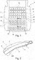
- the middle region 6 of the first foam layer 11 also has a plurality of, in the present case, forty-one comfort tubes 50, which are configured in particular with a rectangular cross-section and increase the comfort during first seating and on short driving distances.
- a comfort tube 50 is to be understood as an elevated location of the surface of the foam part 5 facing the seat occupant, which is surrounded by at least one depression 52.
- the recess 52 is about 5 mm to 50 mm deep, preferably 10 mm to 25 mm deep, and most preferably 15 mm to 20 mm deep.
- a comfort tube 50 is thus an at least partially free-standing area of the surface of the foam part 5.
- a comfort tube can be made of solid material or be made partially hollow inside.
- the comfort tubes 50 are integrally formed or connected to the first foam layer 11 and form the seat occupant closest to facing portions of the central region 6 of the foam part 5.
- the comfort tubes 50 are arranged substantially perpendicular to the seat.
- the cross-sections of the comfort tubes 50 are presently rectangular with rounded edges, but may also have any other geometric shape. Between adjacent comfort tubes 50 lie the depressions 52, the depth of which corresponds to the height of the respective comfort tubes 50 over a base area of the first foam layer 11.
- the through holes 55 are in the present case of circular cylindrical design and are preferably located centrally in the associated comfort tube 50. Cross sections of the through holes 55 deviating from a circular cylindrical shape, for example polygonal cross sections or elliptical cross sections, are also possible. Each of the through holes 55 passes completely through the foam member 5, so that air can flow through the through hole 55 therethrough. The through holes 55 extend largely perpendicular to the surface of the central region 6.
- the comfort tubes 50 each have a blind hole 60.
- the blind holes 60 are present in the form of a circular cylinder and are preferably located centrally in the associated comfort tube 50. Cross sections of the blind holes 60 deviating from a circular cylindrical shape, for example polygonal cross sections or elliptical cross sections, are also possible.
- Each of the blind holes 60 runs starting from a surface of the foam part 5 into the foam part 5, without completely passing through the foam part 5.
- the surface may be the seat occupant facing surface of the foam part 5, which is also referred to as A-side.
- the surface may also be the seat occupant remote from the underside of the foam part 5, which is also referred to as B-side.
- Each of the blind holes 60 is thus open only on one side, so that no air can flow through the blind hole 60 therethrough.
- the blind holes 60 extend largely perpendicular to the surface of the central region 6.
- the depth of a blind hole 60 in a comfort tube 50 affects the compliance of this comfort tube 50.
- the depth of a blind hole 60 in a comfort tube 50 may be less than, equal to or greater than the height of the comfort tube 50.
- the seating comfort and the seat climate can be influenced in a targeted manner.
- the through holes 55 allow for effective air and moisture exchange through the foam member 5, advantageously even without active ventilation means such as fans. It is therefore a purely passive climate system.
- the two foam layers 11 and 21 there is a network formed as nonwoven 225, which constitutes a boundary between the two foam layers 11 and 21.
- the two foam layers 11 and 21 are each materially and / or positively connected to the web 225.
- the web 225 is preferably aligned perpendicular to the through holes 55 and the blind holes 60.
- the fleece 225 is formed flat and without holes, so that the fleece 225 passes through the holes 55.
- the fleece 225 may also be perforated in the area of the holes 55.
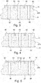
- FIG. 3 shows a section through the foam part 5.
- the web 225 connects directly to the recesses 52 between the individual comfort tubes 50, so that only the comfort tubes 50 form the first foam layer 11.
- the comfort tubes 50 are initially substantially compressed.
- the second foam layer 21 is significantly compressed.
- a two-stage Einsitz is achieved with increasing pad hardness.
- the cut in FIG. 3 shows only through holes 55.
- the comfort tubes 50 of the foam part 5 and blind holes 60 are provided.
- the distribution of the comfort tubes 50, the blind holes 60 have, over the central region 6 is possible in many ways.
- the depth of a blind hole 60 may correspond to the depth of the depressions 52 surrounding the comfort tube 50 and thus to the height of the comfort tubes 50.
- a bottom of the blind hole 60 then coincides with the web 225.
- the depth of the blind holes 60 may be smaller or larger. In the latter case, the fleece 225 may be perforated accordingly.
- FIG. 4 a first modification of the first embodiment is shown.
- the fleece 225 is arranged lower in comparison to the first embodiment, so that the dividing plane between the two foam layers 11 and 21 is lower, that is further away from the occupant.
- the comfort tubes 50 are initially substantially compressed.
- the cut in FIG. 4 shows only through holes 55.
- comfort tubes 50 of the foam member 5 and blind holes 60 may be provided.
- the distribution of the comfort tubes 50, the blind holes 60 have, over the central region 6 is possible in many ways.
- FIG. 5 a second modification of the first embodiment is shown.
- the fleece 225 is arranged higher in comparison to the first embodiment, so that the separation between the two foam layers 11 and 21 is within the comfort tubes 50, that is closer to the occupant.
- substantially the upper portions of the comfort tubes 50 associated with the first foam layer 11 are initially substantially compressed.
- the lower portions of the comfort tubes 50 which belong to the second foam layer 21, more compressed and ultimately also located below the comfort tubes 50 areas of the second foam layer 21.
- the cut in FIG. 5 shows a comfort tube 50 with a blind hole 60, surrounded by two comfort tubes 50, each with a through hole 55.
- the distribution of the comfort tubes 50 with blind holes 60 over the central region 6 is possible in many ways.
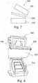
- An in Fig. 6 illustrated second embodiment is designed as a foam part 105 for a seat back.
- the foam part 105 comprises a middle region 106 and two side cheeks 107.
- the foam part 5 of the first exemplary embodiment and the foam part 105 enclose in the installed and useful position an angle of, for example, approximately approximately 90 degrees.
- a first foam layer 111 of the foam part 105 is oriented in the vehicle approximately vertically and in the direction of travel forward, so that the user with the back, possibly with the interposition of other upholstery components, such as in particular a fabric or leather cover, in some areas with the first foam layer 111 in contact is.
- first foam layer 111 In installation position behind the first foam layer 111 is a in the FIG. 6 arranged invisible second foam layer, in particular also aligned approximately vertically and in particular integrally connected to the first foam layer 111.
- the second foam layer is preferably made of hard foam.
- the first foam layer 111 and the second foam layer are foamed in a tool and have mutually different hardnesses and densities.
- the first foam layer 111 also has a plurality of comfort tubes 150, which increase comfort during first seating and on short distances.
- the lower, harder second foam layer however, strengthens the long-term comfort.
- Recesses 152 whose depth corresponds to the height of the respective comfort tubes 150 over a base area of the first foam layer 111, lie between adjacent comfort tubes 150.
- a through-hole 155 is provided in some of the comfort tubes 150, which extends completely through the foam part 105.
- the remaining comfort tubes 150 each have exactly one blind hole 160.
- the distribution of the comfort tubes 150 with blind holes 160 over the central area 106 is possible in many ways.
- the first foam layer 111 and the second foam layer are preferably made in the MDI (diphenylmethane diisocyanate) or TDI (toluene diisocyanate) foaming process.
- the foam hardnesses are in known, typical areas.
- the foam part 105 comprises a first foam layer 111, but no further, in particular no second, foam layer.
- This structure is preferably selected when a very small foam thickness of the foam part 105 is to be achieved or a simple tool structure is to be realized.
- the production of the foam parts 5 and 105 according to the invention takes place in a tool 500.
- the tool 500 comprises a dish-like lower part 510, a frame 520 pivotable relative to the lower part 510, which spans a fleece 225 as an intermediate insert, and a lid-like upper part 530 which can be pivoted relative to the frame 520
- the tool contours for producing the comfort tubes 50 and 150 are provided in the lower part 510, so that the foam part 5 is manufactured upside down in the vehicle relative to its installation position.
- the material for the first foam layer 11, 111 is introduced into the lower part 510. Subsequently, the frame 520 is pivoted together with the spanned nonwoven 225 on the lower part 510, so that the nonwoven 225 rests on the surface of the second foam layer 21, 221. In a second foaming process, the material for the second foam layer 21 is introduced into the space between the frame 520 and the upper part 530 and the upper part 530 is subsequently closed.
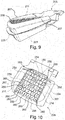
- FIGS. 9 and 10 represented third embodiment corresponds largely to the first embodiment, as far as it is not described otherwise.
- Like-acting components and contours have higher reference numbers by 200 compared to the first exemplary embodiment.
- a manufacturing method and a tool for the third embodiment likewise correspond in each case largely to the production method and tool described above.
- the third embodiment is a foam member 205 for a seat cushion of the vehicle seat.
- the foam part 205 comprises a middle region 206 and two side cheeks 207.
- the first foam layer 211 is preferably made of flexible foam.
- a second foam layer 221 is arranged, in particular also aligned approximately horizontally and integrally connected to the first foam layer 211.
- the second foam layer 221 consists of a foam material that is stronger than the foam material of the first foam layer 211, preferably of hard foam.
- the two foam layers 211 and 221 are foamed in a tool and have mutually different hardnesses and densities.
- the first foam layer 211 also has a plurality of, in this case, forty-three comfort tubes 250, which have a substantially rectangular cross-section. Some of these comfort tubes 250 have an approximately square cross-section. Recesses 252, whose depth corresponds to the height of the respective comfort tubes 250 over a base area of the first foam layer 211, lie between adjacent comfort tubes 250.
- the comfort tubes 250 are divided into three arrays of immediately adjacent comfort tubes 250.
- the boundaries of the fields are formed by pad attachment channels 254.
- the cushion attachment channels 254 provide multiple passages for first attachment means attached to a seat cover and cooperating with these first attachment means and inserted into the foam part 205 second attachment means.
- the known fastening means such as wires and hooks, are not shown in the figures.
- comfort tubes 250 In a front field of comfort tubes 250 positioned below the thighs of an occupant, ie in the front region of the middle region 206 of the foam part 205, seventeen comfort tubes 250 are distributed over the entire width of the middle region 206. Thirteen comfort tubes 250 are distributed in each case in two further rear panels of comfort tubes 250, each positioned in a region below the seatbone bumps of the occupant. In the transverse direction, each of the two fields is between one Cushion attachment channel 254 in the center of the seat and each one adjacent to one of the two side cheeks 207 cushion mounting channel 254. The distribution and shape of the comfort tubes 250 in the two fields is mirror-symmetrical to each other.
- the comfort tubes 250 are integrally connected to the first foam layer 211 and form the closest to the seat occupant portions of the central region 206 of the foam part 205.
- the comfort tubes 250 are arranged substantially perpendicular to the seat.
- the cross-sections of the comfort tubes 250 are presently rectangular with rounded edges, but may also have any other geometric shape.
- a through-hole 255 is provided in each of the comfort tubes 250, which extends completely through the foam part 205.
- Other comfort tubes 250 each have exactly one blind hole 260.
- the distribution of the comfort tubes 250, having blind holes 260, across the central region 206 is possible in a variety of ways.
- Individual comfort tubes 250 which are arranged adjacent to the side cheeks 207, are formed of solid material and thus have neither a through hole 255 nor a blind hole 260. In the present case, in a front row of comfort tubes 250 viewed in the direction of travel, all comfort tubes 250 are each provided with a blind hole 260.
- the two foam layers 211 and 221 are each bonded and / or positively connected to the web 225.
- the web 225 is preferably oriented perpendicular to the holes 255.
- the fleece 225 is formed flat without holes, so that the fleece 225 passes through the holes 255.
- the fleece 225 may also be perforated in the area of the holes 255.
- FIG. 11 illustrated fourth embodiment corresponds largely to the first embodiment, as far as it is not described otherwise.
- Like-acting components and contours have higher reference numbers by 300 compared to the first exemplary embodiment.
- a manufacturing method and a tool for the fourth embodiment likewise correspond in each case largely to the production method and tool described above.
- the fourth embodiment is a foam member 305 for a seat cushion of the vehicle seat.
- the foam part 305 comprises a central region 306 and two side cheeks 307.
- the foam part 305 is foamed from only exactly one foam material, so that it has only exactly one foam layer, namely a first foam layer 311.
- the foam part 305 has a plurality of comfort tubes 350, which have a substantially rectangular cross-section. Individual ones of these comfort tubes 350 have an approximately square cross-section. Between adjacent comfort tubes 350 are depressions 352 having different depths.
- the comfort tubes 350 are divided into two arrays of immediately adjacent comfort tubes 350.
- the boundaries of the fields are largely formed by pad attachment channels 354.
- the cushion attachment channels 354 provide multiple passages for first attachment means attached to a seat cover and cooperating with these first attachment means and in the foam part 305 introduced second fastening means.
- the known fastening means, such as wires and hooks are in FIG. 11 not shown.
- the comfort tubes 350 are integrally connected to the first foam layer 311 and form the closest to the seat occupant portions of the central portion 306 of the foam member 305.
- the comfort tubes 350 are arranged substantially perpendicular to the seat.
- the cross-sections of the comfort tubes 350 are presently rectangular with rounded edges, but may also have any other geometric shape.
- one through-hole 355 or two through-holes 355 are provided in each of the comfort tubes 350.
- the through-holes 355 are in the present case of circular-cylindrical design and are preferably located centrally in the associated comfort tube 350. Cross-sections of the through-holes 355 deviating from a circular cylindrical shape, for example polygonal cross sections or elliptical cross sections, are also possible.
- Comfort tubes 350 are provided in the middle of the middle region 306 with two mutually offset, parallel through-holes 355. Each of the through holes 355 passes completely through the foam member 305 so that air can flow through the through hole 355.
- the through-holes 355 run largely perpendicular to the surface of the central region 306.
- Some of the comfort tubes 350 each have a blind hole 360 or two blind holes 360.
- Individual comfort tubes 350 may have a through hole 355 and a blind hole 360.
- the blind holes 360 are present in the form of a circular cylinder and are preferably located centrally in the associated comfort tube 350. Cross sections of the blind holes 360 deviating from a circular cylindrical shape, for example polygonal cross sections or elliptical cross sections, are also possible.
- Each of the blind holes 360 extends from a surface of the foam part 305 into the foam part 305, without completely passing through the foam member 305 therethrough. The surface may be the seat occupant facing surface of the foam member 305, which is also referred to as A-side.
- the surface may also be the underside of the foam part 305 facing away from the seat occupant, which is also referred to as the B side.
- Each of the blind holes 360 is thus open only on one side, so that no air can flow through the blind hole 360.
- the blind holes 360 extend largely perpendicular to the surface of the central region 306.
- the depth of a blind hole 360 in a comfort tube 350 affects the compliance of this comfort tube 350.
- the depth of a blind hole 360 in a comfort tube 350 may be less than, equal to or greater than the height of the comfort tube 350.
- Individual comfort tubes 350 which are presently arranged adjacent to the side cheeks 307 are formed of solid material and thus have neither a through hole 355 nor a blind hole 360.
- the seating comfort and the seat climate can be influenced in a targeted manner.
- the side cheeks 7, 107, 207 of a third foam material that is compared to the foam material of the second foam layer 21, 221 firmer and / or harder.
- the parting plane between the first foam layer 11, 111, 211 and the second foam layer 21, 221 then does not extend through the side cheeks 7, 107, 207.
- the side cheeks 307 consist of a second foam material.
Landscapes
- Engineering & Computer Science (AREA)
- Aviation & Aerospace Engineering (AREA)
- Transportation (AREA)
- Mechanical Engineering (AREA)
- Manufacturing & Machinery (AREA)
- Mattresses And Other Support Structures For Chairs And Beds (AREA)
- Seats For Vehicles (AREA)
- Chair Legs, Seat Parts, And Backrests (AREA)
Claims (14)
- Pièce en mousse (5, 105, 205, 305) pour un siège de véhicule, comprenant plusieurs protubérances de confort (50, 150, 250, 350) orientées vers un occupant, dans laquelle plusieurs desdites protubérances de confort (50, 150, 250, 350) comprennent chacune un trou (55, 155, 255, 355, 60, 160, 260, 360) ou une pluralité de trous (55, 155, 255, 355, 60, 160, 260, 360), et au moins l'un des trous (55, 155, 255, 355, 60, 160, 260, 360) étant conçu sous forme de trou borgne (60, 160, 260, 360), le trou borgne (60, 160, 260, 360) partant d'une surface de la pièce en mousse (5, 105, 205, 305) orientée vers l'occupant, caractérisée en ce que
les protubérances de confort (50, 150, 250, 350) sont des zones de pièce en mousse surélevées et des évidements (52, 152, 252, 352) sont situés entre les protubérances de confort adjacentes (50, 150, 250, 350). - Pièce en mousse (5, 105, 205, 305) selon la revendication 1, caractérisée en ce que les évidements (52, 152, 252, 352) ont une profondeur comprise entre 5 mm et 50 mm, en particulier entre 10 mm et 25 mm de profondeur.
- Pièce en mousse (5, 105, 205, 305) selon l'une des revendications 1 à 2, caractérisée en ce qu'au moins une protubérance de confort (50, 150, 250, 350) ne comporte qu'un seul trou borgne (60, 160, 260, 360).
- Pièce en mousse (5, 105, 205, 305) selon l'une des revendications 1 à 3, caractérisée en ce qu'au moins une protubérance de confort (50, 150, 250, 350) présente une pluralité de trous borgnes (60, 160, 260, 360).
- Pièce en mousse (5, 105, 205, 305) selon l'une des revendications 1 à 4, caractérisée en ce qu'au moins une protubérance de confort (50, 150, 250, 350) comprend un trou borgne (60, 160, 260, 360) et un trou traversant (55, 155, 255, 355).
- Pièce en mousse (5, 105, 205, 305) selon l'une des revendications 1 à 5, caractérisée en ce qu'au moins un trou borgne (60, 160, 260, 360), à partir d'une surface de la pièce en mousse (5, 105, 205, 305) orientée vers un occupant, s'étend dans la pièce en mousse (5, 105, 205, 305) dans une direction approximativement perpendiculaire à la surface.
- Pièce en mousse (5, 105, 205, 305) selon l'une des revendications 1 à 6, caractérisée en ce qu'au moins un trou borgne (60, 160, 260, 360), partant d'une surface de la pièce en mousse (5, 105, 205, 305) éloignée de l'occupant, s'étend dans la pièce en mousse (5, 105, 205, 305) dans la direction de fermeture d'un outil destiné à produire la pièce en mousse (5, 105, 205, 305).
- Pièce en mousse (5, 105, 205, 305) selon l'une des revendications 1 à 7, caractérisée en ce que la profondeur d'au moins un trou borgne (60, 160, 260, 360) correspond à la hauteur de la protubérance de confort associée (50, 150, 250, 350).
- Pièce en mousse (5, 105, 205, 305) selon l'une des revendications 1 à 8, caractérisée en ce que la profondeur d'au moins un trou borgne (60, 160, 260, 360) est inférieure à la hauteur de la protubérance de confort associée (50, 150, 250, 350).
- Pièce en mousse (5, 105, 205, 305) selon l'une des revendications 1 à 9, caractérisée en ce que la profondeur d'au moins un trou borgne (60, 160, 260, 360) est supérieure à la hauteur de la protubérance de confort associé (50, 150, 250, 350).
- Pièce en mousse (5, 105, 205, 305) selon l'une des revendications 1 à 10, caractérisée en ce qu'au moins deux trous borgnes (60, 160, 260, 360) ont des profondeurs différentes l'un par rapport à l'autre.
- Pièce en mousse (5, 105, 205, 305) selon l'une des revendications 1 à 11, caractérisée en ce qu'au moins un trou borgne (60, 160, 260, 360) a une profondeur de 5 mm à 100 mm, en particulier de 20 mm à 80 mm.
- Siège de véhicule comportant un dossier et un coussin de siège, caractérisé en ce que le dossier et/ou le coussin de siège comprend une pièce en mousse (5, 105, 205, 305) selon l'une des revendications 1 à 12.
- Siège de véhicule selon la revendication 13, caractérisé en ce qu'une rangée de protubérances de confort (50, 250, 350) d'une pièce en mousse (5, 205, 305) du coussin du siège, la plus éloignée vers l'avant dans la direction de déplacement, présente au moins un trou borgne (60, 260, 360).
Priority Applications (1)
| Application Number | Priority Date | Filing Date | Title |
|---|---|---|---|
| PL14811929T PL3083327T3 (pl) | 2013-12-20 | 2014-12-15 | Część piankowa, zwłaszcza do siedzenia pojazdu i siedzenie pojazdu |
Applications Claiming Priority (4)
| Application Number | Priority Date | Filing Date | Title |
|---|---|---|---|
| DE102013226862 | 2013-12-20 | ||
| DE102013226865 | 2013-12-20 | ||
| DE102014209845.9A DE102014209845A1 (de) | 2013-12-20 | 2014-05-23 | Schaumteil, insbesondere für eine Fahrzeugsitz und Fahrzeugsitz |
| PCT/EP2014/077742 WO2015091348A1 (fr) | 2013-12-20 | 2014-12-15 | Pièce en mousse, en particulier pour un siège de véhicule et siège de véhicule |
Publications (2)
| Publication Number | Publication Date |
|---|---|
| EP3083327A1 EP3083327A1 (fr) | 2016-10-26 |
| EP3083327B1 true EP3083327B1 (fr) | 2018-10-17 |
Family
ID=53275562
Family Applications (1)
| Application Number | Title | Priority Date | Filing Date |
|---|---|---|---|
| EP14811929.0A Active EP3083327B1 (fr) | 2013-12-20 | 2014-12-15 | Pièce en mousse, en particulier pour un siège de véhicule et siège de véhicule |
Country Status (9)
| Country | Link |
|---|---|
| US (1) | US10065545B2 (fr) |
| EP (1) | EP3083327B1 (fr) |
| JP (1) | JP6295334B2 (fr) |
| KR (1) | KR101756629B1 (fr) |
| CN (1) | CN105899402B (fr) |
| CA (1) | CA2934390C (fr) |
| DE (2) | DE102014209846A1 (fr) |
| PL (1) | PL3083327T3 (fr) |
| WO (2) | WO2015091348A1 (fr) |
Families Citing this family (21)
| Publication number | Priority date | Publication date | Assignee | Title |
|---|---|---|---|---|
| US10881218B2 (en) | 2015-09-30 | 2021-01-05 | Roger Thomas Mascull and Elizabeth Jocelyn Mascuall | Overlay cushion with removable contouring members |
| CN107054185A (zh) * | 2016-12-30 | 2017-08-18 | 芜湖瑞泰汽车零部件有限公司 | 一种汽车座椅机构的制作方法 |
| RU2733828C1 (ru) | 2017-04-11 | 2020-10-07 | Хуавей Текнолоджиз Ко., Лтд. | Способ, устройство и система для сетевой аутентификации |
| US10245983B1 (en) * | 2017-09-21 | 2019-04-02 | Ford Global Technologies Llc | Off-road performance seat |
| US10343567B1 (en) * | 2018-01-11 | 2019-07-09 | Honda Motor Co., Ltd. | Seat covering and method of forming same |
| DE102018105488B4 (de) * | 2018-03-09 | 2021-01-21 | F.S. Fehrer Automotive Gmbh | Polsterelement für einen Fahrzeugsitz |
| US10556526B2 (en) | 2018-04-30 | 2020-02-11 | Faurecia Automotive Seating, Llc | Ventilated vehicle seat with passive vent panel |
| DE102019113056B3 (de) | 2019-05-17 | 2020-08-13 | Odenwald-Chemie Gmbh | Verfahren zur Herstellung eines Hohlprofilbauteils, Formwerkzeug und Hohlprofilbauteil |
| ES3026740T3 (en) * | 2020-10-06 | 2025-06-12 | Toscana Gomma S P A | Seat for vehicle |
| JP7124032B2 (ja) * | 2020-10-28 | 2022-08-23 | 本田技研工業株式会社 | 成型品の製造方法 |
| US12269384B2 (en) | 2021-03-31 | 2025-04-08 | Lear Corporation | Seat support |
| US12319183B2 (en) | 2021-03-31 | 2025-06-03 | Lear Corporation | Seat support |
| US11807143B2 (en) | 2021-12-02 | 2023-11-07 | Lear Corporation | Vehicle seating system and method for producing same |
| US12325168B2 (en) | 2021-12-20 | 2025-06-10 | Lear Corporation | System and method of making a mesh cushion |
| US12479143B2 (en) | 2021-12-20 | 2025-11-25 | Lear Corporation | System and method of making a mesh cushion |
| US12384094B2 (en) | 2022-03-08 | 2025-08-12 | Lear Corporation | Method for producing a vehicle interior component |
| US12454111B2 (en) | 2022-05-11 | 2025-10-28 | Lear Corporation | Tool to manufacture a cushion |
| WO2023244543A1 (fr) * | 2022-06-14 | 2023-12-21 | Lear Corporation | Maille plastique extrudée, ensemble siège, coussin et/ou procédé de formation |
| US12509343B2 (en) | 2023-02-28 | 2025-12-30 | Lear Corporation | Automated trench manufacturing and assembly for attaching trim covers to a cushion assembly |
| US12325624B2 (en) | 2023-03-06 | 2025-06-10 | Lear Corporation | Seat assembly, cushion, and tool and method of forming |
| US12286044B2 (en) | 2023-05-12 | 2025-04-29 | Lear Corporation | Method and apparatus for producing a vehicle interior component |
Family Cites Families (26)
| Publication number | Priority date | Publication date | Assignee | Title |
|---|---|---|---|---|
| US2588823A (en) * | 1949-04-25 | 1952-03-11 | Glassman Jacob | Rubber foam cushion |
| DE1908883U (de) * | 1963-12-03 | 1965-01-21 | Pirelli Sapsa Spa | Polsterkoerper aus elastischem schwammmaterial nach art von kissen, matratzen od. dgl. |
| US3522282A (en) * | 1968-02-29 | 1970-07-28 | M & T Chemicals Inc | Process for preparing dibutyltin maleate |
| DE1953004A1 (de) * | 1968-05-24 | 1971-04-29 | Dunlopillo Gmbh | Verfahren zur Herstellung eines Fahrzeugsitzes |
| CH640124A5 (de) * | 1979-09-20 | 1983-12-30 | Matra Ag | Schaumstoffkoerper fuer eine matratze und liegemoebel mit einer matratze. |
| US5430901A (en) * | 1993-06-10 | 1995-07-11 | Farley; David L. | Anatomically conformable therapeutic mattress overlay |
| JP3214282B2 (ja) * | 1995-03-06 | 2001-10-02 | トヨタ自動車株式会社 | 車両用シート構造 |
| IT1295564B1 (it) * | 1997-06-05 | 1999-05-13 | Luciana Morson | Materasso anatomico in materiale elastico |
| JP3584424B2 (ja) * | 1997-08-29 | 2004-11-04 | 株式会社岡村製作所 | 多層異硬度クッション体の製造方法と、その方法により製造される多層異硬度クッション体、及びそのクッション体を用いた椅子の座と背 |
| DE29805926U1 (de) * | 1998-04-01 | 1999-07-29 | Johnson Controls GmbH, 51399 Burscheid | Sitzpolster für Fahrzeugsitze |
| JP4300377B2 (ja) * | 1999-09-01 | 2009-07-22 | 株式会社イノアックコーポレーション | シート用パッド |
| WO2001032392A1 (fr) * | 1999-10-29 | 2001-05-10 | The Dow Chemical Company | Procede de fabrication d'articles en mousse multicouches et produits ainsi obtenus |
| DE10016350A1 (de) | 2000-04-03 | 2001-10-31 | Johnson Controls Gmbh & Co Kg | Schaumteil und Verfahren zu seiner Herstellung |
| DE20202042U1 (de) | 2002-02-11 | 2002-06-27 | F. S. Fehrer Automotive Foam GmbH, 97318 Kitzingen | Schaumstoffformteil mit Zonen unterschiedlicher Materialeigenschaften und Vorrichtung zur Herstellung derartiger Schaumstoffformteile |
| JP4221251B2 (ja) * | 2003-06-30 | 2009-02-12 | 株式会社タイカ | 体圧分散型クッション材 |
| WO2006102751A1 (fr) * | 2005-03-30 | 2006-10-05 | Woodbridge Foam Corporation | Element de siege en mousse, moule pour sa fabrication et procede de fabrication du moule |
| NO324518B1 (no) * | 2005-10-31 | 2007-11-05 | Ekornes Asa | Polstring til mobel |
| CA2922187C (fr) * | 2006-05-05 | 2020-06-02 | Nubatech Inc. | Structures matelassees pour parties du corps |
| GB2441418A (en) * | 2006-08-30 | 2008-03-05 | Lear Corp | Vehicle seat cushion with holes to make regions of the cushion softer than others |
| DE202007002196U1 (de) | 2007-02-14 | 2007-05-10 | Isringhausen Gmbh & Co. Kg | Sitz-Schaumpolster und Zwischenlage |
| JP4293281B1 (ja) * | 2007-07-23 | 2009-07-08 | 株式会社ブリヂストン | 車両用シートパッド及び車両用シート |
| PL2138348T3 (pl) * | 2008-06-24 | 2013-09-30 | Fiat Ricerche | Korpus podtrzymujący fotela samochodowego |
| DE102009011736A1 (de) | 2009-03-09 | 2010-09-16 | Johnson Controls Gmbh | Fahrzeugsitzpolster |
| US7946655B2 (en) | 2009-06-10 | 2011-05-24 | Hsu Tsung-Yung | Seat cushion structure |
| DE102013209465B4 (de) * | 2013-01-04 | 2017-01-12 | Johnson Controls Gmbh | Schaumteil, insbesondere für einen Fahrzeugsitz, sowie Werkzeug und Verfahren zur Herstellung eines Schaumteils |
| US9706851B2 (en) * | 2014-07-30 | 2017-07-18 | James Malkiewicz | Mattress core |
-
2014
- 2014-05-23 DE DE102014209846.7A patent/DE102014209846A1/de not_active Ceased
- 2014-05-23 DE DE102014209845.9A patent/DE102014209845A1/de not_active Ceased
- 2014-12-15 KR KR1020167019692A patent/KR101756629B1/ko active Active
- 2014-12-15 JP JP2016541039A patent/JP6295334B2/ja active Active
- 2014-12-15 US US15/105,958 patent/US10065545B2/en active Active
- 2014-12-15 CA CA2934390A patent/CA2934390C/fr active Active
- 2014-12-15 WO PCT/EP2014/077742 patent/WO2015091348A1/fr not_active Ceased
- 2014-12-15 WO PCT/EP2014/077752 patent/WO2015091355A1/fr not_active Ceased
- 2014-12-15 EP EP14811929.0A patent/EP3083327B1/fr active Active
- 2014-12-15 PL PL14811929T patent/PL3083327T3/pl unknown
- 2014-12-15 CN CN201480069618.1A patent/CN105899402B/zh active Active
Non-Patent Citations (1)
| Title |
|---|
| None * |
Also Published As
| Publication number | Publication date |
|---|---|
| US20160318428A1 (en) | 2016-11-03 |
| CN105899402A (zh) | 2016-08-24 |
| WO2015091355A1 (fr) | 2015-06-25 |
| CA2934390A1 (fr) | 2015-06-25 |
| US10065545B2 (en) | 2018-09-04 |
| EP3083327A1 (fr) | 2016-10-26 |
| KR101756629B1 (ko) | 2017-07-11 |
| DE102014209845A1 (de) | 2015-06-25 |
| WO2015091348A1 (fr) | 2015-06-25 |
| DE102014209846A1 (de) | 2015-06-25 |
| JP2016540690A (ja) | 2016-12-28 |
| JP6295334B2 (ja) | 2018-03-14 |
| PL3083327T3 (pl) | 2019-04-30 |
| KR20160101149A (ko) | 2016-08-24 |
| CN105899402B (zh) | 2018-11-20 |
| CA2934390C (fr) | 2019-06-25 |
Similar Documents
| Publication | Publication Date | Title |
|---|---|---|
| EP3083327B1 (fr) | Pièce en mousse, en particulier pour un siège de véhicule et siège de véhicule | |
| EP2941366B1 (fr) | Piece de mousse, en particulier pour un siege de vehicule et procede et outil pour produire un piece de mousse | |
| EP1962644B1 (fr) | Unité à éléments à ressorts utilisée pour un élément de rembourrage, en particulier un matelas | |
| DE102013202688B4 (de) | Sitzkissen für einen Fahrzeugsitz | |
| EP1068094B1 (fr) | Coussin pour siège d'automobile | |
| EP1417114B1 (fr) | Piece de capitonnage climatisee pour siege de vehicule automobile | |
| DE2510182C3 (de) | Sitz- bzw. Rückenpolster, insbesondere für Fahrzeugsitze | |
| DE102009057072B4 (de) | Polster mit Belüftung für einen Fahrzeugsitz | |
| DE102005018445B3 (de) | Klimatisierungseinrichtung für einen Sitz | |
| DE102017112267A1 (de) | Passiver angepasster sitz mit luft-/flüssigkeitshybridzellen | |
| EP2517928B1 (fr) | Siège de véhicule et procédé destiné à la fabrication d'un élément de rembourrage de siège de véhicule | |
| WO2018229185A1 (fr) | Pièce de rembourrage d'un siège de véhicule à moteur comprenant un non-tissé moulé 3d entouré de mousse pour le renforcement d'une joue latérale | |
| EP1806258B1 (fr) | Pièce de capitonnage climatisé, en particulier pour un siège passif climatisé | |
| DE102014225684B4 (de) | Pneumatische Verstellanordnung für einen Fahrzeugsitz, sowie Fahrzeugsitz | |
| DE102010014664B4 (de) | Polsterelement, insbesondere eine Matratze | |
| EP2411243B1 (fr) | Unité d'accoudoir de siège de passager | |
| EP0870447B1 (fr) | Elément de rembourrage en matériau mousse | |
| DE102011122011B4 (de) | Fahrzeugsitz mit Polsterteil mit Nahtbereich | |
| DE102009006276A1 (de) | Arbeitsstuhl mit luftgepolsterten Stützflächen | |
| EP2607156B1 (fr) | Siège de véhicule, procédé de fabrication d'une pièce de rembourrage d'un siège de véhicule et utilisation d'une pièce à matricer à chaud | |
| DE202005006360U1 (de) | Klimatisierungseinrichtung für einen Sitz |
Legal Events
| Date | Code | Title | Description |
|---|---|---|---|
| PUAI | Public reference made under article 153(3) epc to a published international application that has entered the european phase |
Free format text: ORIGINAL CODE: 0009012 |
|
| 17P | Request for examination filed |
Effective date: 20160720 |
|
| AK | Designated contracting states |
Kind code of ref document: A1 Designated state(s): AL AT BE BG CH CY CZ DE DK EE ES FI FR GB GR HR HU IE IS IT LI LT LU LV MC MK MT NL NO PL PT RO RS SE SI SK SM TR |
|
| AX | Request for extension of the european patent |
Extension state: BA ME |
|
| DAX | Request for extension of the european patent (deleted) | ||
| RAP1 | Party data changed (applicant data changed or rights of an application transferred) |
Owner name: ADIENT LUXEMBOURG HOLDING S.A R.L. |
|
| RAP1 | Party data changed (applicant data changed or rights of an application transferred) |
Owner name: ADIENT LUXEMBOURG HOLDING S.A R.L. |
|
| GRAP | Despatch of communication of intention to grant a patent |
Free format text: ORIGINAL CODE: EPIDOSNIGR1 |
|
| RIC1 | Information provided on ipc code assigned before grant |
Ipc: B60N 2/56 20060101ALI20180528BHEP Ipc: B29C 44/04 20060101ALI20180528BHEP Ipc: B29K 105/04 20060101ALI20180528BHEP Ipc: B29L 31/58 20060101ALI20180528BHEP Ipc: B29K 75/00 20060101ALI20180528BHEP Ipc: B29L 31/00 20060101ALI20180528BHEP Ipc: B60N 2/70 20060101AFI20180528BHEP Ipc: B60N 2/427 20060101ALI20180528BHEP Ipc: B29C 44/06 20060101ALI20180528BHEP |
|
| INTG | Intention to grant announced |
Effective date: 20180704 |
|
| GRAS | Grant fee paid |
Free format text: ORIGINAL CODE: EPIDOSNIGR3 |
|
| GRAA | (expected) grant |
Free format text: ORIGINAL CODE: 0009210 |
|
| AK | Designated contracting states |
Kind code of ref document: B1 Designated state(s): AL AT BE BG CH CY CZ DE DK EE ES FI FR GB GR HR HU IE IS IT LI LT LU LV MC MK MT NL NO PL PT RO RS SE SI SK SM TR |
|
| REG | Reference to a national code |
Ref country code: GB Ref legal event code: FG4D Free format text: NOT ENGLISH |
|
| REG | Reference to a national code |
Ref country code: CH Ref legal event code: EP |
|
| REG | Reference to a national code |
Ref country code: IE Ref legal event code: FG4D Free format text: LANGUAGE OF EP DOCUMENT: GERMAN |
|
| REG | Reference to a national code |
Ref country code: DE Ref legal event code: R096 Ref document number: 502014009819 Country of ref document: DE Ref country code: AT Ref legal event code: REF Ref document number: 1053593 Country of ref document: AT Kind code of ref document: T Effective date: 20181115 |
|
| REG | Reference to a national code |
Ref country code: NL Ref legal event code: MP Effective date: 20181017 |
|
| REG | Reference to a national code |
Ref country code: LT Ref legal event code: MG4D |
|
| PG25 | Lapsed in a contracting state [announced via postgrant information from national office to epo] |
Ref country code: NL Free format text: LAPSE BECAUSE OF FAILURE TO SUBMIT A TRANSLATION OF THE DESCRIPTION OR TO PAY THE FEE WITHIN THE PRESCRIBED TIME-LIMIT Effective date: 20181017 |
|
| PG25 | Lapsed in a contracting state [announced via postgrant information from national office to epo] |
Ref country code: ES Free format text: LAPSE BECAUSE OF FAILURE TO SUBMIT A TRANSLATION OF THE DESCRIPTION OR TO PAY THE FEE WITHIN THE PRESCRIBED TIME-LIMIT Effective date: 20181017 Ref country code: IS Free format text: LAPSE BECAUSE OF FAILURE TO SUBMIT A TRANSLATION OF THE DESCRIPTION OR TO PAY THE FEE WITHIN THE PRESCRIBED TIME-LIMIT Effective date: 20190217 Ref country code: NO Free format text: LAPSE BECAUSE OF FAILURE TO SUBMIT A TRANSLATION OF THE DESCRIPTION OR TO PAY THE FEE WITHIN THE PRESCRIBED TIME-LIMIT Effective date: 20190117 Ref country code: LT Free format text: LAPSE BECAUSE OF FAILURE TO SUBMIT A TRANSLATION OF THE DESCRIPTION OR TO PAY THE FEE WITHIN THE PRESCRIBED TIME-LIMIT Effective date: 20181017 Ref country code: HR Free format text: LAPSE BECAUSE OF FAILURE TO SUBMIT A TRANSLATION OF THE DESCRIPTION OR TO PAY THE FEE WITHIN THE PRESCRIBED TIME-LIMIT Effective date: 20181017 Ref country code: BG Free format text: LAPSE BECAUSE OF FAILURE TO SUBMIT A TRANSLATION OF THE DESCRIPTION OR TO PAY THE FEE WITHIN THE PRESCRIBED TIME-LIMIT Effective date: 20190117 Ref country code: LV Free format text: LAPSE BECAUSE OF FAILURE TO SUBMIT A TRANSLATION OF THE DESCRIPTION OR TO PAY THE FEE WITHIN THE PRESCRIBED TIME-LIMIT Effective date: 20181017 Ref country code: FI Free format text: LAPSE BECAUSE OF FAILURE TO SUBMIT A TRANSLATION OF THE DESCRIPTION OR TO PAY THE FEE WITHIN THE PRESCRIBED TIME-LIMIT Effective date: 20181017 |
|
| PG25 | Lapsed in a contracting state [announced via postgrant information from national office to epo] |
Ref country code: RS Free format text: LAPSE BECAUSE OF FAILURE TO SUBMIT A TRANSLATION OF THE DESCRIPTION OR TO PAY THE FEE WITHIN THE PRESCRIBED TIME-LIMIT Effective date: 20181017 Ref country code: AL Free format text: LAPSE BECAUSE OF FAILURE TO SUBMIT A TRANSLATION OF THE DESCRIPTION OR TO PAY THE FEE WITHIN THE PRESCRIBED TIME-LIMIT Effective date: 20181017 Ref country code: SE Free format text: LAPSE BECAUSE OF FAILURE TO SUBMIT A TRANSLATION OF THE DESCRIPTION OR TO PAY THE FEE WITHIN THE PRESCRIBED TIME-LIMIT Effective date: 20181017 Ref country code: GR Free format text: LAPSE BECAUSE OF FAILURE TO SUBMIT A TRANSLATION OF THE DESCRIPTION OR TO PAY THE FEE WITHIN THE PRESCRIBED TIME-LIMIT Effective date: 20190118 Ref country code: PT Free format text: LAPSE BECAUSE OF FAILURE TO SUBMIT A TRANSLATION OF THE DESCRIPTION OR TO PAY THE FEE WITHIN THE PRESCRIBED TIME-LIMIT Effective date: 20190217 |
|
| REG | Reference to a national code |
Ref country code: DE Ref legal event code: R097 Ref document number: 502014009819 Country of ref document: DE |
|
| PG25 | Lapsed in a contracting state [announced via postgrant information from national office to epo] |
Ref country code: IT Free format text: LAPSE BECAUSE OF FAILURE TO SUBMIT A TRANSLATION OF THE DESCRIPTION OR TO PAY THE FEE WITHIN THE PRESCRIBED TIME-LIMIT Effective date: 20181017 Ref country code: DK Free format text: LAPSE BECAUSE OF FAILURE TO SUBMIT A TRANSLATION OF THE DESCRIPTION OR TO PAY THE FEE WITHIN THE PRESCRIBED TIME-LIMIT Effective date: 20181017 |
|
| REG | Reference to a national code |
Ref country code: CH Ref legal event code: PL |
|
| PLBE | No opposition filed within time limit |
Free format text: ORIGINAL CODE: 0009261 |
|
| STAA | Information on the status of an ep patent application or granted ep patent |
Free format text: STATUS: NO OPPOSITION FILED WITHIN TIME LIMIT |
|
| PG25 | Lapsed in a contracting state [announced via postgrant information from national office to epo] |
Ref country code: EE Free format text: LAPSE BECAUSE OF FAILURE TO SUBMIT A TRANSLATION OF THE DESCRIPTION OR TO PAY THE FEE WITHIN THE PRESCRIBED TIME-LIMIT Effective date: 20181017 Ref country code: SM Free format text: LAPSE BECAUSE OF FAILURE TO SUBMIT A TRANSLATION OF THE DESCRIPTION OR TO PAY THE FEE WITHIN THE PRESCRIBED TIME-LIMIT Effective date: 20181017 Ref country code: RO Free format text: LAPSE BECAUSE OF FAILURE TO SUBMIT A TRANSLATION OF THE DESCRIPTION OR TO PAY THE FEE WITHIN THE PRESCRIBED TIME-LIMIT Effective date: 20181017 Ref country code: MC Free format text: LAPSE BECAUSE OF FAILURE TO SUBMIT A TRANSLATION OF THE DESCRIPTION OR TO PAY THE FEE WITHIN THE PRESCRIBED TIME-LIMIT Effective date: 20181017 Ref country code: LU Free format text: LAPSE BECAUSE OF NON-PAYMENT OF DUE FEES Effective date: 20181215 |
|
| REG | Reference to a national code |
Ref country code: IE Ref legal event code: MM4A |
|
| 26N | No opposition filed |
Effective date: 20190718 |
|
| GBPC | Gb: european patent ceased through non-payment of renewal fee |
Effective date: 20190117 |
|
| REG | Reference to a national code |
Ref country code: BE Ref legal event code: MM Effective date: 20181231 |
|
| PG25 | Lapsed in a contracting state [announced via postgrant information from national office to epo] |
Ref country code: IE Free format text: LAPSE BECAUSE OF NON-PAYMENT OF DUE FEES Effective date: 20181215 Ref country code: SI Free format text: LAPSE BECAUSE OF FAILURE TO SUBMIT A TRANSLATION OF THE DESCRIPTION OR TO PAY THE FEE WITHIN THE PRESCRIBED TIME-LIMIT Effective date: 20181017 |
|
| PG25 | Lapsed in a contracting state [announced via postgrant information from national office to epo] |
Ref country code: BE Free format text: LAPSE BECAUSE OF NON-PAYMENT OF DUE FEES Effective date: 20181231 |
|
| PG25 | Lapsed in a contracting state [announced via postgrant information from national office to epo] |
Ref country code: LI Free format text: LAPSE BECAUSE OF NON-PAYMENT OF DUE FEES Effective date: 20181231 Ref country code: CH Free format text: LAPSE BECAUSE OF NON-PAYMENT OF DUE FEES Effective date: 20181231 Ref country code: GB Free format text: LAPSE BECAUSE OF NON-PAYMENT OF DUE FEES Effective date: 20190117 |
|
| PG25 | Lapsed in a contracting state [announced via postgrant information from national office to epo] |
Ref country code: MT Free format text: LAPSE BECAUSE OF FAILURE TO SUBMIT A TRANSLATION OF THE DESCRIPTION OR TO PAY THE FEE WITHIN THE PRESCRIBED TIME-LIMIT Effective date: 20181017 |
|
| PG25 | Lapsed in a contracting state [announced via postgrant information from national office to epo] |
Ref country code: TR Free format text: LAPSE BECAUSE OF FAILURE TO SUBMIT A TRANSLATION OF THE DESCRIPTION OR TO PAY THE FEE WITHIN THE PRESCRIBED TIME-LIMIT Effective date: 20181017 |
|
| PG25 | Lapsed in a contracting state [announced via postgrant information from national office to epo] |
Ref country code: CY Free format text: LAPSE BECAUSE OF FAILURE TO SUBMIT A TRANSLATION OF THE DESCRIPTION OR TO PAY THE FEE WITHIN THE PRESCRIBED TIME-LIMIT Effective date: 20181017 Ref country code: HU Free format text: LAPSE BECAUSE OF FAILURE TO SUBMIT A TRANSLATION OF THE DESCRIPTION OR TO PAY THE FEE WITHIN THE PRESCRIBED TIME-LIMIT; INVALID AB INITIO Effective date: 20141215 Ref country code: MK Free format text: LAPSE BECAUSE OF NON-PAYMENT OF DUE FEES Effective date: 20181017 |
|
| REG | Reference to a national code |
Ref country code: AT Ref legal event code: MM01 Ref document number: 1053593 Country of ref document: AT Kind code of ref document: T Effective date: 20191215 |
|
| PG25 | Lapsed in a contracting state [announced via postgrant information from national office to epo] |
Ref country code: AT Free format text: LAPSE BECAUSE OF NON-PAYMENT OF DUE FEES Effective date: 20191215 |
|
| REG | Reference to a national code |
Ref country code: DE Ref legal event code: R081 Ref document number: 502014009819 Country of ref document: DE Owner name: ADIENT US LLC, PLYMOUTH, US Free format text: FORMER OWNER: ADIENT LUXEMBOURG HOLDING S.A R.L., LUXEMBOURG, LU |
|
| REG | Reference to a national code |
Ref country code: SK Ref legal event code: PC4A Ref document number: E 29663 Country of ref document: SK Owner name: ADIENT US LLC, PLYMOUTH, US Free format text: FORMER OWNER: ADIENT LUXEMBOURG HOLDING S.A R.L., LUXEMBOURG, LU Effective date: 20240415 |
|
| REG | Reference to a national code |
Ref country code: DE Ref legal event code: R082 Ref document number: 502014009819 Country of ref document: DE Representative=s name: LIEDTKE & PARTNER PATENTANWAELTE, DE |
|
| PGFP | Annual fee paid to national office [announced via postgrant information from national office to epo] |
Ref country code: FR Payment date: 20251226 Year of fee payment: 12 |
|
| PGFP | Annual fee paid to national office [announced via postgrant information from national office to epo] |
Ref country code: CZ Payment date: 20251125 Year of fee payment: 12 |
|
| PGFP | Annual fee paid to national office [announced via postgrant information from national office to epo] |
Ref country code: PL Payment date: 20251118 Year of fee payment: 12 |
|
| PGFP | Annual fee paid to national office [announced via postgrant information from national office to epo] |
Ref country code: SK Payment date: 20251119 Year of fee payment: 12 |
|
| PGFP | Annual fee paid to national office [announced via postgrant information from national office to epo] |
Ref country code: DE Payment date: 20251229 Year of fee payment: 12 |