EP3081737A2 - Bohrgerät zum erstellen einer verrohrten bohrung und verfahren zum betreiben eines bohrgerätes - Google Patents
Bohrgerät zum erstellen einer verrohrten bohrung und verfahren zum betreiben eines bohrgerätes Download PDFInfo
- Publication number
- EP3081737A2 EP3081737A2 EP16153082.9A EP16153082A EP3081737A2 EP 3081737 A2 EP3081737 A2 EP 3081737A2 EP 16153082 A EP16153082 A EP 16153082A EP 3081737 A2 EP3081737 A2 EP 3081737A2
- Authority
- EP
- European Patent Office
- Prior art keywords
- support tube
- depth
- drilling
- drill
- drive
- Prior art date
- Legal status (The legal status is an assumption and is not a legal conclusion. Google has not performed a legal analysis and makes no representation as to the accuracy of the status listed.)
- Granted
Links
- 238000005553 drilling Methods 0.000 title claims abstract description 83
- 238000000034 method Methods 0.000 title claims abstract description 31
- 238000003780 insertion Methods 0.000 claims abstract description 24
- 230000037431 insertion Effects 0.000 claims abstract description 24
- 239000002689 soil Substances 0.000 claims abstract description 20
- 239000000463 material Substances 0.000 claims abstract description 10
- 238000005259 measurement Methods 0.000 claims description 14
- 238000001514 detection method Methods 0.000 claims description 7
- 239000000654 additive Substances 0.000 claims description 2
- 230000000996 additive effect Effects 0.000 claims description 2
- 230000035515 penetration Effects 0.000 abstract description 9
- 238000011161 development Methods 0.000 description 4
- 230000003287 optical effect Effects 0.000 description 3
- 230000008569 process Effects 0.000 description 3
- 238000012937 correction Methods 0.000 description 2
- 230000008878 coupling Effects 0.000 description 2
- 238000010168 coupling process Methods 0.000 description 2
- 238000005859 coupling reaction Methods 0.000 description 2
- 239000003673 groundwater Substances 0.000 description 2
- 238000009434 installation Methods 0.000 description 2
- 230000000454 anti-cipatory effect Effects 0.000 description 1
- 238000009412 basement excavation Methods 0.000 description 1
- 230000005540 biological transmission Effects 0.000 description 1
- 230000008859 change Effects 0.000 description 1
- 230000001419 dependent effect Effects 0.000 description 1
- 238000006073 displacement reaction Methods 0.000 description 1
- 230000000149 penetrating effect Effects 0.000 description 1
- 230000009467 reduction Effects 0.000 description 1
- 239000000725 suspension Substances 0.000 description 1
- 238000002604 ultrasonography Methods 0.000 description 1
Images


Classifications
-
- E—FIXED CONSTRUCTIONS
- E21—EARTH OR ROCK DRILLING; MINING
- E21B—EARTH OR ROCK DRILLING; OBTAINING OIL, GAS, WATER, SOLUBLE OR MELTABLE MATERIALS OR A SLURRY OF MINERALS FROM WELLS
- E21B47/00—Survey of boreholes or wells
- E21B47/09—Locating or determining the position of objects in boreholes or wells, e.g. the position of an extending arm; Identifying the free or blocked portions of pipes
-
- E—FIXED CONSTRUCTIONS
- E02—HYDRAULIC ENGINEERING; FOUNDATIONS; SOIL SHIFTING
- E02D—FOUNDATIONS; EXCAVATIONS; EMBANKMENTS; UNDERGROUND OR UNDERWATER STRUCTURES
- E02D7/00—Methods or apparatus for placing sheet pile bulkheads, piles, mouldpipes, or other moulds
-
- E—FIXED CONSTRUCTIONS
- E21—EARTH OR ROCK DRILLING; MINING
- E21B—EARTH OR ROCK DRILLING; OBTAINING OIL, GAS, WATER, SOLUBLE OR MELTABLE MATERIALS OR A SLURRY OF MINERALS FROM WELLS
- E21B15/00—Supports for the drilling machine, e.g. derricks or masts
- E21B15/003—Supports for the drilling machine, e.g. derricks or masts adapted to be moved on their substructure, e.g. with skidding means; adapted to drill a plurality of wells
-
- E—FIXED CONSTRUCTIONS
- E21—EARTH OR ROCK DRILLING; MINING
- E21B—EARTH OR ROCK DRILLING; OBTAINING OIL, GAS, WATER, SOLUBLE OR MELTABLE MATERIALS OR A SLURRY OF MINERALS FROM WELLS
- E21B19/00—Handling rods, casings, tubes or the like outside the borehole, e.g. in the derrick; Apparatus for feeding the rods or cables
- E21B19/24—Guiding or centralising devices for drilling rods or pipes
-
- E—FIXED CONSTRUCTIONS
- E21—EARTH OR ROCK DRILLING; MINING
- E21B—EARTH OR ROCK DRILLING; OBTAINING OIL, GAS, WATER, SOLUBLE OR MELTABLE MATERIALS OR A SLURRY OF MINERALS FROM WELLS
- E21B3/00—Rotary drilling
- E21B3/02—Surface drives for rotary drilling
- E21B3/022—Top drives
-
- E—FIXED CONSTRUCTIONS
- E21—EARTH OR ROCK DRILLING; MINING
- E21B—EARTH OR ROCK DRILLING; OBTAINING OIL, GAS, WATER, SOLUBLE OR MELTABLE MATERIALS OR A SLURRY OF MINERALS FROM WELLS
- E21B3/00—Rotary drilling
- E21B3/02—Surface drives for rotary drilling
- E21B3/03—Surface drives for rotary drilling with an intermittent unidirectional rotation of the tool
-
- E—FIXED CONSTRUCTIONS
- E21—EARTH OR ROCK DRILLING; MINING
- E21B—EARTH OR ROCK DRILLING; OBTAINING OIL, GAS, WATER, SOLUBLE OR MELTABLE MATERIALS OR A SLURRY OF MINERALS FROM WELLS
- E21B44/00—Automatic control systems specially adapted for drilling operations, i.e. self-operating systems which function to carry out or modify a drilling operation without intervention of a human operator, e.g. computer-controlled drilling systems; Systems specially adapted for monitoring a plurality of drilling variables or conditions
-
- E—FIXED CONSTRUCTIONS
- E21—EARTH OR ROCK DRILLING; MINING
- E21B—EARTH OR ROCK DRILLING; OBTAINING OIL, GAS, WATER, SOLUBLE OR MELTABLE MATERIALS OR A SLURRY OF MINERALS FROM WELLS
- E21B47/00—Survey of boreholes or wells
- E21B47/04—Measuring depth or liquid level
-
- E—FIXED CONSTRUCTIONS
- E21—EARTH OR ROCK DRILLING; MINING
- E21B—EARTH OR ROCK DRILLING; OBTAINING OIL, GAS, WATER, SOLUBLE OR MELTABLE MATERIALS OR A SLURRY OF MINERALS FROM WELLS
- E21B7/00—Special methods or apparatus for drilling
- E21B7/002—Drilling with diversely driven shafts extending into the borehole
-
- E—FIXED CONSTRUCTIONS
- E21—EARTH OR ROCK DRILLING; MINING
- E21B—EARTH OR ROCK DRILLING; OBTAINING OIL, GAS, WATER, SOLUBLE OR MELTABLE MATERIALS OR A SLURRY OF MINERALS FROM WELLS
- E21B7/00—Special methods or apparatus for drilling
- E21B7/02—Drilling rigs characterised by means for land transport with their own drive, e.g. skid mounting or wheel mounting
-
- E—FIXED CONSTRUCTIONS
- E21—EARTH OR ROCK DRILLING; MINING
- E21B—EARTH OR ROCK DRILLING; OBTAINING OIL, GAS, WATER, SOLUBLE OR MELTABLE MATERIALS OR A SLURRY OF MINERALS FROM WELLS
- E21B7/00—Special methods or apparatus for drilling
- E21B7/20—Driving or forcing casings or pipes into boreholes, e.g. sinking; Simultaneously drilling and casing boreholes
Definitions
- the invention relates to a drilling device for creating a cased bore, comprising a first drill drive for rotationally driving a drill string, at the lower end of which a drilling tool for removing soil material is arranged, a mast along which the first drill drive can be moved with a carriage, and a second drive, with which a support tube for the bore can be introduced into the ground, according to the preamble of claim 1.
- the invention further relates to a method for operating a drilling device, with which a bore is created with a support tube, according to claim 6.
- a drill for creating a cased bore is approximately from the EP 1 548 226 A1 known. Cased holes are needed, for example, when creating foundation piles in loose ground.
- the bore is provided with a support tube which stabilizes the bore wall and ensures that no soil material falls into the wellbore and this does not collapse.
- a common method is to introduce a support tube substantially simultaneously with the creation of the bore in the ground.
- a generic drill is used, which has a first drill drive for rotationally driving a drilling tool, is removed by which soil material and discharged from the wellbore. Furthermore, the drill has a second drive, with which the support tube is screwed into the ground.
- the support tube can precede the drilling tool.
- This variant of the method is useful, for example, when groundwater-containing soil layers are cut through, for example.
- the support tube ensures that groundwater does not penetrate into the hole or penetrate into other soil layers.
- An anticipatory introduction of the support tube serves to secure against the foundation breakage.
- the support tube is successively composed of a plurality of tubular elements.
- the drilling tool can precede the support tube. This is particularly useful when penetrating harder soil layers, as facilitated by an advance of the drilling tool, the subsequent introduction of the support tube.
- the two process variants can also be combined with one another, depending on the soil layers to be penetrated.
- the creation of a cased bore requires significant experience of the operator of the drill.
- the invention has for its object to provide a drill for creating a cased bore and a method for operating such a drill, with which a cased bore can be created efficiently and particularly reliable.
- the drilling apparatus is characterized in that a computer unit is provided, in which a current drilling depth of the drilling tool and an insertion depth of the support tube are to be specified and that a monitor is provided, on which by the computer unit, the current drilling depth in relation to the insertion depth of the support tube can be displayed ,
- a basic idea of the invention is to display the current drilling depth in relation to the insertion depth of the support tube to the operator via a computer unit on a monitor.
- the position of support tube and drilling tool is thus readily apparent.
- it can be readily determined whether the support tube precedes the drilling tool or vice versa. This makes it much easier for the operator to create a cased hole.
- it can also change depending on the depth between the process variants, where once a support tube and once the drilling tool leads.
- the appropriate process variant can always be selected. This allows a particularly efficient and thus cost-effective creation of a cased bore.
- the computer unit may be fully or partially integrated in the control of the drill or form an independent unit, which may also be retrofitted.
- a preferred embodiment of the invention is that the second drive is an output element, which is driven by a motor of the first drill drive.
- the first drill drive preferably consists of one or more hydraulic motors. These drive preferably via a corresponding reduction the drill pipe, in particular a telescopic Kelly drill pipe to.
- the torque of the motor of the drill drive is transmitted to the support tube via the annular output element.
- the second drive consists essentially of the transmission, without even having a separate engine.
- the drill mast has only one motor unit with two output options. Once Kellystange and thus the drilling tool is driven via the hollow shaft passage and the other is driven via a flanged at the lower end of the hollow shaft outlet via a preferably interposed Kardangelenk a turntable with which the drill pipe can be screwed.
- the rotary gearbox is provided with Kelly rod carrier cups installed at the top and a turntable flange screwed down at the bottom.
- the first drill drive and the second drive are arranged together on the carriage.
- the carriage also referred to as Bohrantriebsschlitten is moved over a feed winch along the mast.
- the drill string protrudes through the annular first drill drive, wherein the drill string is vertically adjustable with the drilling tool via a main winch on the drill.
- the drill drive preferably forms a lower stop for the drill pipe.
- the second drive is a casing machine, which is attached to a substructure of the drill.
- the casing machine constitutes a drive unit independent of the first drill drive.
- the casing machine may comprise a suitable motor or drive which can exert a required torque and possibly a necessary axial force on the support tube for introduction into the ground.
- the casing has a pivoting collet for rotating insertion of the support tube in the ground.
- the collet can include the support tube by means of hydraulic cylinders and thus produce a rotationally fixed connection to the support tube.
- a rotational movement and a torque can be applied to the support tube, so that this is screwed approximately in the ground.
- a depth of insertion of the support tube is indicated in the ground in a computer unit, detects a current drilling depth of the drilling tool when creating the hole and in the computer unit is specified and by means of the computer unit on a monitor, the current drilling depth is displayed in relation to the insertion depth of the support tube.
- the method is particularly suitable for operating a drilling device described above. This results in the advantages described above.
- the detection of the instantaneous drilling depth of the drilling tool takes place via a first sensor device.
- the sensor device may in particular comprise measuring devices which have a unwound length of the main rope of the main winch for vertical movement of the drill string and / or for determining the unwound length of the feed winch through which the carriage is moved along the mast with the first drill drive.
- other sensor devices for determining the current drilling depth can be used, such as optical sensors or a depth measurement by means of ultrasound or laser.
- a further advantageous embodiment of the method according to the invention is that the inputting of the insertion depth of the support tube takes place manually via an operating terminal or automatically via a second sensor device.
- the length of the support tube can be entered by the operator directly into the computer unit as a measure of the penetration depth, for example via a corresponding input field which can be displayed on the monitor. It is assumed that the support tube is introduced in total in the soil.
- the input may also be automatic, such as by means for reading a corresponding mark on the support tube, such as an RFID tag. In this mark, all the essential information about the support tube, in particular over the length and thus the penetration depth of the support tube, be stored. Furthermore, it is preferably provided to determine an instantaneous insertion depth of the support tube by the second sensor device.
- the instantaneous insertion depth of the support tube can be reliably determined by a corresponding sensor device. This can be done for example by detecting the movement of the collet or also via optical sensors for determining the position of the support tube.
- a preferred variant of the method according to the invention is that the detection of the current drilling depth by means of a position measurement of a carriage of a first drill drive and / or a position measurement of a drill string, at the lower end of the drilling tool is attached.
- the sensor devices described above can be used.
- a representation of the current drilling depth in relation to the insertion depth of the support tube can be done in basically any way.
- the current position of the drilling tool to the lower end of the support tube is particularly clear and illustrative.
- the support tube may be illustrated in a cross-sectional view with two lateral lines and a corresponding horizontal transverse line for defining a lower and an upper edge.
- the drilling tool may be pictorially or stylized as a horizontal bar in the support tube.
- the inventive method is further developed in an advantageous manner that the support tube is composed of at least two support tube elements, wherein an additive overall representation of the penetration depth is provided.
- the maximum insertion depth of the support tube is increased and adjusted accordingly. Accordingly, the presentation changes on the monitor.
- the support tube with the above-added additional support tube element is then introduced further into the ground, the insertion depth and the relevant representation on the monitor changed accordingly.
- the introduced support tube can be composed of a plurality of support tube elements of different lengths.
- the length of the individual support tube elements can be entered into the computer unit via a corresponding input field, which can be displayed on the monitor.
- the input can also be made by a selection of predetermined standard lengths of support tube elements.
- an automatic detection and input is provided, such as with a previously described RFID tag on the support tube element.
- a further preferred embodiment of the method according to the invention consists in that the support tube or the support tube element is displayed on the monitor on the monitor before and after insertion into the ground.
- the support tube is shown with the above-added additional support tube element in an initial state on the monitor.
- the support tube or the corresponding support tube element is above a ground surface shown.
- the inserted support tube is shown with the maximum insertion depth or the actual, currently achieved insertion depth.
- the support or drill pipe can be screwed into the subsoil both with the rotary drive which can be displaced on the mast of the drill by means of a turntable and with the piping system.
- the current penetration depth of the drill pipe can be determined by means of the sensors mounted on the feed system.
- the position of the rotary drive along the mast is determined and charged with the current drilling depth of the drilling tool.
- the position of the rotary drive can be done via displacement transducer along the mast or transducer on the feed system, for example on the feed rope.
- the total length of the drill pipe can be determined either by entering the driver or by automatic detection of the individual drill pipe shots using, for example, RFID tags.
- the length of the individual drill pipe shots is summed to a total drill pipe length.
- the drilling depth of the drilling tool can be determined, for example, via the depth measurement of the main winch, which moves the Kelly bar, and the current locking position of the Kelly bar. But it is also possible to specify by entering the driver a zero position of the boring depth when reaching the Bohrrohroberkante by the drill bit sole.
- the current drilling depth can be calculated with the previously calculated drill pipe total length and a difference between the drilling depth and the drill pipe installation length can be determined.
- the installation depth of the drill pipe is determined by a measuring system on the drill mast, it must be determined by switching or triggering whether the drill pipe is screwed in or the drill pipe is drilled out. This trigger can be done automatically either by entering the driver or automatic turntable by pressing the pipe fixtures.
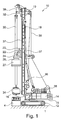
- An inventive drill 10 according to Fig. 1 has a trained as a crawler undercarriage 12 and a rotatably mounted thereon superstructure 14.
- the undercarriage 12 and the uppercarriage 14 form a substructure 15.
- the drive units and the operator station for the drill 10 are arranged in a known manner.
- a vertical mast 18 with an upper mast head 19 is adjustably mounted via a Anschkinematik 16 with neck cylinders.
- a carriage 20 is slidably guided.
- a first drill drive 22 is provided which has a hydraulic motor 24.
- a second drive 26 with a sleeve-shaped rotary joint 27 for producing a rotationally fixed connection to a support tube 4 is provided on the carriage 20.
- the second drive 26 consists essentially of a gear connection to the first drill drive 22 with the hydraulic motor 24, so as to apply a torque to the rotary joint 27 and thus the support tube 4.
- the approximately sleeve-shaped first drill drive 22 is penetrated by a drill string 30, which is designed as a Kelly linkage with outer Mitêtartn.
- the drill string 30 has an upper suspension 32, with which the drill pipe 30 is connected to a main cable 39.
- the main cable 39 is guided over pulleys on the mast head 19 to a main winch 38 at the top of the upper carriage 14. By operating the main winch 38, the drill pipe 30 can be moved vertically.
- the carriage 20 is connected to a feed cable 37, which is guided above and below the carriage 20 along the mast 18 and by a feed winch 36 is pressed. By the feed winch 36, the carriage 20 along a guide of the mast 18 can be moved up or down.
- a drilling tool 34 for removing soil material is attached on a lower side of the drill string 30, a drilling tool 34 for removing soil material is attached.
- the drilling tool 34 is in the illustrated embodiment according to Fig. 1 as a drilling bucket.
- the diameter of the drilling tool 34 is designed so that it can be inserted into the inner cavity of the support tube 4.
- a cased bore in the bottom 1 can be created.
- a coordinated introduction of the support tube 4 with the sinking of the bore is necessary.
- the support tube 4 is introduced into the ground 1 up to a first penetration depth.
- FIG. 2a shows a bar chart provided according to the invention that can be displayed on a monitor to the operator in the drill 10. As shown Fig. 2a there is still no excavation done.
- the tube length of the support tube 4 can be entered by the operator on the monitor of a computer unit.
- a lower edge of the drilling tool 34 is set to zero at the upper edge of the support tube.
- the relation between drilling tool 34 and support tube 4 is set in the computer unit.
- Fig. 2b As a next step, the bottom 1 is bored out of the support tube 4 with the drilling tool 34.
- the progress of drilling on the monitor of the computer unit can be controlled.
- Both the length of the support tube 4 and the drilling depth achieved are displayed graphically on the monitor of the computer unit.
- the shifted downward horizontal bar within the support tube 4 in Fig. 2b indicates the drilling depth of the drilling tool 34.
- the drilling tool 34 can be displayed with an additional horizontal bar within the support tube 4 on the monitor in the control station.
- the difference of the support tube length and the achieved drilling depth as a measured value of the position of the drilling tool 34 to the support tube 4 on Monitor are displayed.
- the device driver in addition to the graph receives a measure of whether bored with the drilling tool 34 relative to the support tube 4 leading or lagging. This measure is of crucial importance in certain soil layers for the subsequent quality of the bored pile produced.
- the support tube 4 is again coupled to the second drive 26, which may also be referred to as a power rotary head, and further screwed into the bottom 1.
- the recording of the new reference of the depth measurement is done by a reset of the device driver with the lower edge of the drilling tool 34 at the upper edge of the support tube 4 or by measuring the depth of penetration reached via the depth measurement on the feed winch 36 by means of a second sensor device.
- a special mode for input by the device driver or an automatic detection of the coupling of the second drive 26 with the support tube 4 can take place in the computer unit.
- Fig. 2e the placement of an additional support tube element 5, whereby an extended support tube 4 is formed.
- the length of the support tube 4 is determined in the computer unit and graphically according to Fig. 2e shown.
- the length of the additionally mounted support tube element 5 is added to the previously known length of the support tube 4.
- the recognition of the length of the additional mounted support tube element 5 is done by entering the device driver in the computer unit or by an automatic detection of the tube length by an identification system of the support tubes 4 / support tube elements 5, such as by means of an RFID tag.
- FIGS. 2a to 2i The method shown shows a leading edge of the support tube 4 with respect to the bore 2.
- the graphical representation of this is readily controllable for the operator.
- a leading edge of the bore relative to the support tube can take place.
Landscapes
- Engineering & Computer Science (AREA)
- Mining & Mineral Resources (AREA)
- Life Sciences & Earth Sciences (AREA)
- Geology (AREA)
- Physics & Mathematics (AREA)
- General Life Sciences & Earth Sciences (AREA)
- Geochemistry & Mineralogy (AREA)
- Fluid Mechanics (AREA)
- Environmental & Geological Engineering (AREA)
- Mechanical Engineering (AREA)
- Geophysics (AREA)
- Structural Engineering (AREA)
- General Engineering & Computer Science (AREA)
- Civil Engineering (AREA)
- Paleontology (AREA)
- Earth Drilling (AREA)
Abstract
Description
- Die Erfindung betrifft ein Bohrgerät zum Erstellen einer verrohrten Bohrung, mit einem ersten Bohrantrieb zum drehenden Antreiben eines Bohrgestänges, an dessen unterem Ende ein Bohrwerkzeug zum Abtragen von Bodenmaterial angeordnet ist, einem Mast, entlang welchem der erste Bohrantrieb mit einem Schlitten verfahrbar ist, und einem zweiten Antrieb, mit welchem ein Stützrohr für die Bohrung in den Boden einbringbar ist, gemäß dem Oberbegriff des Anspruchs 1.
- Die Erfindung betrifft weiterhin ein Verfahren zum Betreiben eines Bohrgerätes, mit dem eine Bohrung mit einem Stützrohr erstellt wird, gemäß dem Anspruch 6.
- Ein Bohrgerät zum Erstellen einer verrohrten Bohrung ist etwa aus der
EP 1 548 226 A1 bekannt. Verrohrte Bohrungen werden beispielsweise beim Erstellen von Gründungspfählen in lockerem Boden benötigt. Die Bohrung ist dabei mit einem Stützrohr versehen, welche die Bohrungswand stabilisiert und sicherstellt, dass kein Bodenmaterial in das Bohrloch fällt und dieses nicht kollabiert. - Es bestehen grundsätzlich verschiedene Verfahren, ein Stützrohr an einer Bohrung vorzusehen. So ist es bekannt, vor dem Ausheben von Bodenmaterial ein Stützrohr mittels eines Rüttlers oder einer Ramme einzubringen. Anschließend kann das Bodenmaterial innerhalb des Stützrohres abgetragen und ausgehoben werden. Dieses Verfahren zum Erstellen einer verrohrten Bohrung ist nur bei bestimmten Bodenverhältnissen möglich.
- Weiterhin ist es bekannt, zunächst eine Bohrung zu erstellen und anschließend das Stützrohr in die Bohrung einzubringen. Auch dieses Verfahren ist nur bei bestimmten Bodenverhältnissen zweckmäßig, da die Bohrungswand bis zum Einbringen des Stützrohres hinreichend stabil sein muss.
- Ein gebräuchliches Verfahren besteht darin, ein Stützrohr im Wesentlichen gleichzeitig mit dem Erstellen der Bohrung in den Boden einzubringen. Zu diesem Zweck wird ein gattungsgemäßes Bohrgerät eingesetzt, welches einen ersten Bohrantrieb zum drehenden Antreiben eines Bohrwerkzeuges aufweist, durch welchen Bodenmaterial abgetragen und aus dem Bohrloch abgefördert wird. Weiterhin weist das Bohrgerät einen zweiten Antrieb auf, mit welchem das Stützrohr in den Boden eingedreht wird.
- Bei diesen bekannten Verfahren bestehen zwei grundsätzliche Verfahrensvarianten. So kann gemäß einer Variante das Stützrohr dem Bohrwerkzeug vorauseilen. Diese Verfahrensvariante ist beispielsweise dann sinnvoll, wenn etwa grundwasserhaltige Bodenschichten durchschnitten werden. Das Stützrohr stellt dabei sicher, dass Grundwasser nicht in die Bohrung eindringt oder in andere Bodenschichten vordringen kann. Ein vorauseilendes Einbringen des Stützrohres dient einer Sicherung gegen den Grundbruch. Abhängig von der gewünschten Tiefe der Verrohrung wird das Stützrohr nacheinander aus mehreren Rohrelementen zusammengesetzt.
- Gemäß einer Verfahrensvariante kann das Bohrwerkzeug dem Stützrohr vorauseilen. Dies ist insbesondere beim Durchdringen härterer Bodenschichten sinnvoll, da durch ein Vorauseilen des Bohrwerkzeuges das nachfolgende Einbringen des Stützrohres erleichtert wird.
- Während des Abteufens einer Bohrung können die beiden Verfahrensvarianten abhängig von den zu durchdringenden Bodenschichten auch miteinander kombiniert werden. Dabei bedarf das Erstellen einer verrohrten Bohrung einer erheblichen Erfahrung des Bedieners des Bohrgerätes.
- Der Erfindung liegt die Aufgabe zugrunde, ein Bohrgerät zum Erstellen einer verrohrten Bohrung und ein Verfahren zum Betreiben eines solchen Bohrgerätes anzugeben, mit welchen eine verrohrte Bohrung effizient und besonders zuverlässig erstellt werden kann.
- Die Aufgabe wird nach der Erfindung zum einen durch ein Bohrgerät mit den Merkmalen des Anspruchs 1 und zum anderen durch ein Verfahren mit den Merkmalen des Anspruchs 6 gelöst. Bevorzugte Ausführungsformen der Erfindung sind in den jeweils abhängigen Ansprüchen angegeben.
- Das erfindungsgemäße Bohrgerät ist dadurch gekennzeichnet, dass eine Rechnereinheit vorgesehen ist, in welcher eine momentane Bohrtiefe des Bohrwerkzeuges und eine Einbringtiefe des Stützrohres anzugeben sind und dass ein Monitor vorgesehen ist, auf welchem durch die Rechnereinheit die momentane Bohrtiefe im Verhältnis zur Einbringtiefe des Stützrohres darstellbar ist.
- Ein Grundgedanke der Erfindung liegt darin, über eine Rechnereinheit auf einem Monitor dem Bediener die momentane Bohrtiefe im Verhältnis zur Einbringtiefe des Stützrohres darzustellen. Für einen Bediener ist somit ohne weiteres die Lage von Stützrohr und Bohrwerkzeug erkennbar. Insbesondere kann ohne weiteres bestimmt werden, ob das Stützrohr dem Bohrwerkzeug vorauseilt oder umgekehrt. Dies erleichtert dem Bediener in ganz erheblicher Weise das Erstellen einer verrohrten Bohrung. Insbesondere kann er auch abhängig von der Tiefe zwischen den Verfahrensvarianten wechseln, wobei einmal ein Stützrohr und einmal das Bohrwerkzeug vorauseilt. Beim Erstellen einer Bohrung durch unterschiedliche Bodenschichten kann so stets die geeignete Verfahrensvariante ausgewählt werden. Dies ermöglicht ein besonders effizientes und damit kostengünstiges Erstellen einer verrohrten Bohrung.
- Die Rechnereinheit kann ganz oder teilweise in der Steuerung des Bohrgerätes integriert sein oder eine davon unabhängige Einheit bilden, welche auch nachrüstbar sein kann.
- Eine bevorzugte Ausführungsform der Erfindung besteht darin, dass der zweite Antrieb ein Abtriebselement ist, welches von einem Motor des ersten Bohrantriebes angetrieben ist. Der erste Bohrantrieb besteht dabei vorzugsweise aus einem oder mehreren Hydraulikmotoren. Diese treiben vorzugsweise über eine entsprechende Untersetzung das Bohrgestänge, insbesondere ein teleskopierbares Kelly-Bohrgestänge, an. Zum Einbringen des Stützrohres wird über das ringförmige Abtriebselement das Drehmoment des Motors des Bohrantriebes auf das Stützrohr übertragen. In diesem Fall besteht der zweite Antrieb im Wesentlichen aus dem Getriebe, ohne selbst einen eigenständigen Motor aufzuweisen.
- Am Bohrgerätemast befindet sich nur eine Motoreinheit mit zwei Abtriebsmöglichkeiten. Einmal wird über den Hohlwellendurchgang die Kellystange und damit das Bohrwerkzeug angetrieben und zum andern wird über einen am unteren Ende der Hohlwelle angeflanschten Abgang über ein vorzugsweise dazwischen geschaltetes Kardangelenk ein Drehteller angetrieben, mit dem das Bohrrohr eingedreht werden kann. Das Drehgetriebe ist mit oben eingebauten Mitnehmerschalen für die Kellystange und einem unten anschraubten Flansch für den Drehtellerantrieb vorgesehen.
- Dabei ist es nach einer Weiterbildung der Erfindung besonders bevorzugt, dass der erste Bohrantrieb und der zweite Antrieb gemeinsam auf dem Schlitten angeordnet sind. Der Schlitten, auch als Bohrantriebsschlitten bezeichnet, wird über eine Vorschubwinde entlang des Mastes verfahren. Vorzugsweise ragt das Bohrgestänge durch den ringförmigen ersten Bohrantrieb hindurch, wobei das Bohrgestänge mit dem Bohrwerkzeug über eine Hauptwinde am Bohrgerät vertikal verstellbar ist. Der Bohrantrieb bildet vorzugsweise einen unteren Anschlag für das Bohrgestänge.
- Eine alternative Weiterbildung der Erfindung besteht darin, dass der zweite Antrieb eine Verrohrungsmaschine ist, welche an einem Unterbau des Bohrgerätes angebracht ist. Die Verrohrungsmaschine stellt eine vom ersten Bohrantrieb unabhängige Antriebseinheit dar. Die Verrohrungsmaschine kann einen geeigneten Motor oder Antrieb aufweisen, welcher ein nötiges Drehmoment und gegebenenfalls eine nötige Axialkraft auf das Stützrohr zum Einbringen in den Boden ausüben kann.
- Dabei ist nach der Erfindung eine bevorzugte Ausführungsform dadurch gegeben, dass die Verrohrungsmaschine eine schwenkbare Spannzange zum drehenden Einbringen des Stützrohres in den Boden aufweist. Die Spannzange kann mittels Hydraulikzylindern das Stützrohr umfassen und so eine drehfeste Verbindung zu dem Stützrohr herstellen. Über weitere Schwenkzylinder kann eine Drehbewegung und ein Drehmoment auf das Stützrohr aufgebracht werden, so dass dieses etwa in den Boden eingeschraubt wird.
- Nach dem erfindungsgemäßen Verfahren zum Betreiben eines Bohrgerätes, bei dem eine Bohrung mit einem Stützrohr erstellt wird, ist vorgesehen, dass eine Einbringtiefe des Stützrohres in den Boden in einer Rechnereinheit angegeben wird, eine momentane Bohrtiefe des Bohrwerkzeuges beim Erstellen der Bohrung erfasst und in der Rechnereinheit angegeben wird und mittels der Rechnereinheit auf einem Monitor die momentane Bohrtiefe im Verhältnis zu der Einbringtiefe des Stützrohres dargestellt wird.
- Das Verfahren ist insbesondere zum Betreiben eines zuvor beschriebenen Bohrgerätes geeignet. Hierbei ergeben sich die zuvor beschriebenen Vorteile.
- Nach einer Weiterbildung des erfindungsgemäßen Verfahrens ist es bevorzugt, dass das Erfassen der momentanen Bohrtiefe des Bohrwerkzeuges über eine erste Sensoreinrichtung erfolgt. Die Sensoreinrichtung kann dabei insbesondere Messeinrichtungen auffassen, welche eine abgespulte Länge des Hauptseiles der Hauptwinde zum vertikalen Verfahren des Bohrgestänges und/oder zum Ermitteln der abgespulten Länge der Vorschubwinde aufweisen, durch welche der Schlitten mit dem ersten Bohrantrieb entlang des Mastes verfahren wird. Grundsätzlich sind jedoch auch andere Sensoreinrichtungen zum Ermitteln der momentanen Bohrtiefe einsetzbar, etwa optische Sensoren oder eine Tiefenmessung mittels Ultraschall oder Laser.
- Eine weitere vorteilhafte Ausführungsform des erfindungsgemäßen Verfahrens liegt darin, dass das Eingeben der Einbringtiefe des Stützrohres manuell über ein Bedienterminal oder automatisch über eine zweite Sensoreinrichtung erfolgt. Es kann die Länge des Stützrohres als Maß für die Eindringtiefe von dem Bediener direkt in die Rechnereinheit eingegeben werden, beispielsweise über ein entsprechendes Eingabenfeld, welches auf dem Monitor anzeigbar ist. Dabei wird davon ausgegangen, dass das Stützrohr insgesamt in den Boden eingebracht wird. Die Eingabe kann auch automatisch erfolgen, etwa durch eine Einrichtung zum Lesen einer entsprechenden Markierung an dem Stützrohr, etwa einer RFID-Marke. In dieser Marke können alle wesentlichen Informationen zum Stützrohr, insbesondere über die Länge und damit die Eindringtiefe des Stützrohres, gespeichert sein. Des Weiteren ist es vorzugsweise vorgesehen, eine momentane Einbringtiefe des Stützrohres durch die zweite Sensoreinrichtung zu bestimmen. Dies kann dabei ebenfalls, abhängig von der Art der Antriebsanordnung, über eine entsprechende Lagebestimmung des Schlittens mit dem zweiten Antrieb zum Einbringen des Stützrohres oder durch entsprechende optische Sensoren erfolgen. Auch bei der Verwendung einer Verrohrungsmaschine kann die momentane Einbringtiefe des Stützrohres durch eine entsprechende Sensoreinrichtung zuverlässig ermittelt werden. Dies kann beispielsweise über ein Erfassen der Bewegung der Spannzange oder ebenfalls über optische Sensoren zur Lageermittlung des Stützrohres durchgeführt werden.
- Eine bevorzugte Verfahrensvariante besteht nach der Erfindung darin, dass das Erfassen der momentanen Bohrtiefe mittels einer Positionsmessung eines Schlittens eines ersten Bohrantriebes und/oder eine Lagemessung eines Bohrgestänges erfolgt, an deren unterem Ende das Bohrwerkzeug angebracht ist. Hierzu können die zuvor beschriebenen Sensoreinrichtungen verwendet werden.
- Eine Darstellung der momentanen Bohrtiefe im Verhältnis zur Einbringtiefe des Stützrohres kann in grundsätzlich beliebiger Weise erfolgen.
- Eine besonders anschauliche Darstellung ergibt sich nach einer Weiterbildung der Erfindung dadurch, dass durch die Rechnereinheit auf dem Monitor eine Balkendarstellung der Eindringtiefe des Stützrohres und der momentanen Bohrtiefe erzeugt wird. Insbesondere bei einer vertikalen Ausrichtung der Balken wird die momentane Lage des Bohrwerkzeuges zu dem unteren Ende des Stützrohres besonders deutlich und anschaulich. Insbesondere kann das Stützrohr in einer Querschnittsansicht mit zwei seitlichen Linien und einer entsprechenden horizontalen Querlinie zur Definierung einer unteren und einer oberen Kante dargestellt werden. Das Bohrwerkzeug kann bildlich oder stilisiert als horizontaler Balken in dem Stützrohr angezeigt sein.
- Dabei ist das erfindungsgemäße Verfahren in vorteilhafter Weise dadurch weitergebildet, dass das Stützrohr aus mindestens zwei Stützrohrelementen zusammengesetzt wird, wobei eine additive Gesamtdarstellung der Eindringtiefe vorgesehen wird. Durch eine entsprechende Eingabe der Länge eines zusätzlichen Stützrohres wird die maximale Einbringtiefe des Stützrohres entsprechend erhöht und angepasst. Entsprechend ändert sich die Darstellung auf dem Monitor. Sofern das Stützrohr mit dem oben angesetzten zusätzlichen Stützrohrelement dann weiter in den Boden eingebracht wird, verändert sich die Einbringtiefe und die diesbezügliche Darstellung auf dem Monitor entsprechend. Grundsätzlich kann das eingebrachte Stützrohr aus einer Vielzahl unterschiedlich langer Stützrohrelemente zusammengesetzt werden. Die Länge der einzelnen Stützrohrelemente kann über ein entsprechendes Eingabefeld, welches an dem Monitor anzeigbar ist, in die Rechnereinheit eingegeben werden. Grundsätzlich kann die Eingabe auch durch eine Auswahl vorgegebener Standardlängen von Stützrohrelementen erfolgen. Vorzugsweise ist eine automatische Erkennung und Eingabe vorgesehen, etwa mit einer zuvor beschriebenen RFID-Marke an dem Stützrohrelement.
- Eine weitere bevorzugte Ausführungsvariante des erfindungsgemäßen Verfahrens besteht darin, dass das Stützrohr oder das Stützrohrelement auf dem Monitor vor und nach dem Einbringen in den Boden auf dem Monitor dargestellt wird. So wird auf dem Monitor das Stützrohr mit dem oben angesetzten zusätzlichen Stützrohrelement in einem Ausgangszustand gezeigt. Dabei befindet sich das Stützrohr oder das entsprechende Stützrohrelement oberhalb einer dargestellten Bodenoberfläche. Nach dem entsprechenden Einbringen wird das eingebrachte Stützrohr mit der maximalen Einbringtiefe oder der tatsächlichen, momentan erreichten Einbringtiefe dargestellt.
- Das Stütz- oder Bohrrohr kann sowohl mit dem am Mast des Bohrgeräts verschiebbaren Drehantrieb mittels Drehteller als auch mit der Verrohrungsanlage in den Baugrund eingedreht werden. Beim Eindrehen des Bohrrohrs mittels Drehteller kann die aktuelle Eindringtiefe des Bohrrohrs mittels der am Vorschubsystem angebrachten Messaufnehmer ermittelt werden. Dazu wird die Stellung des Drehantriebs längs des Mastes ermittelt und mit der aktuellen Bohrtiefe des Bohrwerkzeugs verrechnet. Die Stellung des Drehantriebs kann dabei über Wegaufnehmer längs des Mastes oder über Wegaufnehmer am Vorschubsystem, beispielsweise am Vorschubseil erfolgen.
Die Gesamtlänge des Bohrrohres kann dabei entweder durch Eingabe des Fahrers oder durch automatische Erkennung der einzelnen Bohrrohrschüsse mittels beispielsweise RFID- Tags ermittelt werden. Die Länge der einzelnen Bohrrohrschüsse wird zu einer Bohrrohrgesamtlänge summiert. Die Bohrtiefe des Bohrwerkzeugs kann beispielsweise über die Tiefenmessung der Hauptseilwinde, welche die Kellystange bewegt, und der aktuellen Verriegelstellung der Kellystange ermittelt werden. Es besteht aber auch die Möglichkeit, durch Eingabe des Fahrers eine Nullstellung der Ausbohrtiefe bei Erreichen der Bohrrohroberkante durch die Bohrwerkzeugsohle festzulegen. Damit kann die aktuelle Ausbohrtiefe mit der zuvor berechneten Bohrrohrgesamtlänge verrechnet werden und eine Differenz zwischen Ausbohrtiefe und Bohrrohreinbaulänge ermittelt werden. - Wird die Einbautiefe des Bohrrohrs über ein Messsystem am Bohrgerätemast ermittelt, muss durch eine Umschaltung oder Triggern festgelegt werden, ob das Bohrrohr eingedreht wird oder das Bohrrohr ausgebohrt wird. Dieser Trigger kann dabei entweder durch Eingabe des Fahrers oder bei Automatikdrehtellern, durch Betätigen der Rohrbefestigungseinrichtungen automatisch erfolgen.
- Die Erfindung wird nachfolgend anhand von bevorzugten Ausführungsbeispielen weiter beschrieben, welche schematisch in den beigefügten Zeichnungen dargestellt sind. In den Zeichnungen zeigen:
- Fig. 1:
- eine schematische Seitenansicht eines erfindungsgemäßen Bohrgerätes und
- Figuren 2a bis 2i:
- Balkendarstellungen zu einem Stützrohr und einer Bohrung gemäß der Erfindung.
- Ein erfindungsgemäßes Bohrgerät 10 gemäß
Fig. 1 weist einen als Raupenfahrwerk ausgebildeten Unterwagen 12 und einen darauf drehbar gelagerten Oberwagen 14 auf. Der Unterwagen 12 und der Oberwagen 14 bilden einen Unterbau 15. An dem Oberwagen 14 sind in bekannter Weise die Antriebsaggregate und der Bedienstand für das Bohrgerät 10 angeordnet. - An einer Vorderseite des Oberwagens 14 ist über eine Anlenkkinematik 16 mit Nackenzylindern ein vertikaler Mast 18 mit einem oberen Mastkopf 19 verstellbar angebracht. Entlang einer Vorderseite des Mastes 18 ist ein Schlitten 20 verschiebbar geführt. Auf dem Schlitten 20 ist ein erster Bohrantrieb 22 vorgesehen, welcher einen Hydraulikmotor 24 aufweist. Weiterhin ist an dem Schlitten 20 ein zweiter Antrieb 26 mit einer hülsenförmigen Drehverbindung 27 zum Herstellen einer drehfesten Verbindung zu einem Stützrohr 4 vorgesehen. Der zweite Antrieb 26 besteht im Wesentlichen aus einer Getriebeverbindung zu dem ersten Bohrantrieb 22 mit dem Hydraulikmotor 24, um so ein Drehmoment auf die Drehverbindung 27 und damit das Stützrohr 4 aufzubringen.
- Der etwa hülsenförmige erste Bohrantrieb 22 wird von einem Bohrgestänge 30 durchdrungen, welches als ein Kellygestänge mit äußeren Mitnehmerleisten ausgebildet ist. Hierbei weist das Bohrgestänge 30 eine obere Aufhängung 32 auf, mit welcher das Bohrgestänge 30 mit einem Hauptseil 39 verbunden ist. Das Hauptseil 39 ist über Umlenkrollen am Mastkopf 19 zu einer Hauptwinde 38 an der Oberseite des Oberwagens 14 geführt. Durch Betätigen der Hauptwinde 38 kann das Bohrgestänge 30 vertikal bewegt werden.
- Der Schlitten 20 ist mit einem Vorschubseil 37 verbunden, welches oberhalb und unterhalb des Schlittens 20 entlang des Mastes 18 geführt und von einer Vorschubwinde 36 betätigt ist. Durch die Vorschubwinde 36 kann der Schlitten 20 entlang einer Führung des Mastes 18 nach oben oder unten bewegt werden.
- An einer Unterseite des Bohrgestänges 30 ist ein Bohrwerkzeug 34 zum Abtragen von Bodenmaterial angebracht. Das Bohrwerkzeug 34 ist in dem dargestellten Ausführungsbeispiel nach
Fig. 1 als ein Bohreimer ausgeführt. Der Durchmesser des Bohrwerkzeuges 34 ist dabei so ausgebildet, dass dieses in den inneren Hohlraum des Stützrohres 4 eingeführt werden kann. - Mit dem Bohrgerät 10 kann eine verrohrte Bohrung im Boden 1 erstellt werden. Für ein effizientes Erstellen einer verrohrten Bohrung ist ein abgestimmtes Einbringen des Stützrohres 4 mit dem Abteufen der Bohrung notwendig. Gemäß
Fig. 1 ist in einem ersten Schritt das Stützrohr 4 bis zu einer ersten Eindringtiefe in den Boden 1 eingebracht. - Dieser Zustand ist schematisch in
Fig. 2a gezeigt, welche ein nach der Erfindung vorgesehenes Balkendiagramm zeigt, das auf einem Monitor dem Bediener in dem Bohrgerät 10 angezeigt werden kann. Gemäß der Darstellung nachFig. 2a ist noch kein Bodenaushub erfolgt. - Die Rohrlänge des Stützrohres 4 kann dabei durch den Bediener am Monitor einer Rechnereinheit eingegeben werden. Für die Tiefenmessung wird eine Unterkante des Bohrwerkzeuges 34 an der Oberkante des Stützrohres auf Null gesetzt. Damit ist der Bezug zwischen Bohrwerkzeug 34 und Stützrohr 4 in der Rechnereinheit gesetzt.
- Gemäß
Fig. 2b erfolgt als nächster Schritt ein Ausbohren des Bodens 1 aus dem Stützrohr 4 mit dem Bohrwerkzeug 34. Durch eine Tiefenmessung mit einer ersten Sensoreinrichtung an der Hauptwinde 38 kann der Bohrfortschritt am Monitor der Rechnereinheit kontrolliert werden. Dabei werden sowohl die Länge des Stützrohres 4 als auch die erreichte Bohrtiefe graphisch an dem Monitor der Rechnereinheit angezeigt. Der nach unten verschobene Horizontalbalken innerhalb des Stützrohres 4 inFig. 2b gibt dabei die Bohrtiefe des Bohrwerkzeuges 34 an. Zusätzlich kann das Bohrwerkzeug 34 mit einem zusätzlichen Horizontalbalken innerhalb des Stützrohres 4 auf dem Monitor in den Bedienstand angezeigt werden. - Vorzugsweise kann noch zusätzlich die Differenz der Stützrohrlänge und der erreichten Bohrtiefe als ein Messwert der Stellung des Bohrwerkzeuges 34 zum Stützrohr 4 am Monitor dargestellt werden. Dabei erhält der Gerätefahrer zusätzlich zur graphischen Darstellung ein Maß darüber, ob mit dem Bohrwerkzeug 34 bezogen zum Stützrohr 4 voreilend oder nacheilend gebohrt wird. Dieses Maß ist in bestimmten Bodenschichten von entscheidender Bedeutung für die spätere Qualität des erstellten Bohrpfahls.
- In einem weiteren Schritt gemäß
Fig. 2c wird das Stützrohr 4 abermals mit dem zweiten Antrieb 26, welcher auch als Kraftdrehkopf bezeichnet werden kann, gekoppelt und weiter in den Boden 1 eingedreht. - Die Aufnahme des neuen Bezugs der Tiefenmessung geschieht durch einen Reset des Gerätefahrers mit der Unterkante des Bohrwerkzeugs 34 an der Oberkante des Stützrohrs 4 oder durch die Messung der erreichten Eindringtiefe über die Tiefenmessung an der Vorschubwinde 36 mittels einer zweiten Sensoreinrichtung. Für die Messung des Eindringens über die Tiefenmessung der Vorschubwinde 36 kann in der Rechnereinheit ein spezieller Modus zum Eingeben durch den Gerätefahrer oder eine automatische Erkennung der Kopplung des zweiten Antriebes 26 mit dem Stützrohr 4 erfolgen.
- Gemäß
Fig. 2d erfolgt dann nach Entkopplung des zweiten Antriebes 26 von dem Stützrohr 4 ein weiteres Ausbohren innerhalb des Stützrohres 4. Dies kann in einem oder mehreren Bohrvorgängen erfolgen. - Dabei können die Schritte gemäß den
Figuren 2b bis 2d mehrfach hintereinander durchgeführt werden. - Anschließend erfolgt gemäß
Fig. 2e das Aufsetzen eines zusätzlichen Stützrohrelementes 5, wodurch ein verlängertes Stützrohr 4 gebildet wird. Die Länge des Stützrohres 4 wird in der Rechnereinheit ermittelt und graphisch gemäßFig. 2e dargestellt. - Hierzu wird zur bisher bekannten Länge des Stützrohres 4 die Länge des zusätzlich aufgesetzten Stützrohrelementes 5 addiert. Die Erkennung der Länge des zusätzlich aufgesetzten Stützrohrelementes 5 geschieht durch die Eingabe des Gerätefahrers in die Rechnereinheit oder durch eine automatische Erkennung der Rohrlänge durch ein Identifikationssystem der Stützrohre 4/Stützrohrelemente 5, etwa mittels einer RFID-Marke.
- Um die Tiefenmessung wieder auf die Oberkante des Stützrohres 4 zu beziehen, wird diese durch einen Reset des Gerätefahrers mit der Unterkante des Bohrwerkzeuges 34 an der Oberkante des Stützrohres 4 auf Null gesetzt oder durch eine automatische Korrektur der erreichten Bohrtiefe um die angegebene oder erfasste Länge des mit dem Stützrohrelement 5 ergänzten Stützrohrs 4 angepasst. Hierdurch kann eine Korrektur der Tiefenmessung automatisch erfolgen.
- Durch abermaliges Koppeln des verlängerten Stützrohres 4 mit dem zweiten Antrieb 26 wird das Stützrohr 4 tiefer in den Boden 1 eingedreht, wie aus
Fig. 2f ersichtlich ist. Anschließend erfolgt gemäßFig. 2g ein weiteres Abbohren und Abtragen des Bodenmaterials aus dem Stützrohr 4. Das Eindrehen des verlängerten Stützrohres 4 und das Abbohren des darin befindlichen Bodenmaterials kann ebenfalls in mehreren Schritten erfolgen, wie aus denFiguren 2h und 2i hervorgeht. - Das in den
Figuren 2a bis 2i dargestellte Verfahren zeigt ein Vorauseilen des Stützrohres 4 gegenüber der Bohrung 2. Durch die graphische Darstellung ist dies ohne weiteres für den Bediener kontrollierbar. In entsprechender Weise kann auch ein Vorauseilen der Bohrung gegenüber dem Stützrohr erfolgen.
Claims (12)
- Bohrgerät zum Erstellen einer verrohrten Bohrung (2), mit- einem ersten Bohrantrieb (22) zum drehenden Antreiben eines Bohrgestänges (30), an dessen unterem Ende ein Bohrwerkzeug (34) zum Abtragen von Bodenmaterial angeordnet ist,- einem Mast (18), entlang welchem der erste Bohrantrieb (22) mit einem Schlitten (20) verfahrbar ist, und- einem zweiten Antrieb (26), mit welchem ein Stützrohr (4) für die Bohrung (2) in den Boden (1) einbringbar ist,dadurch gekennzeichnet,- dass eine Rechnereinheit vorgesehen ist, in welcher eine momentane Bohrtiefe des Bohrwerkzeuges (34) und eine Einbringtiefe des Stützrohres (4) angegeben sind, und- dass ein Monitor vorgesehen ist, auf welchem durch die Rechnereinheit die momentane Bohrtiefe im Verhältnis zur Einbringtiefe des Stützrohres (4) darstellbar ist.
- Bohrgerät nach Anspruch 1,
dadurch gekennzeichnet,
dass der zweite Antrieb (26) ein Abtriebselement ist, welches von einem Motor (24) des ersten Bohrantriebes (22) angetrieben ist. - Bohrgerät nach Anspruch 1 oder 2,
dadurch gekennzeichnet,
dass der erste Bohrantrieb (22) und der zweite Antrieb (26) gemeinsam auf dem Schlitten (20) angeordnet sind. - Bohrgerät nach Anspruch 1,
dadurch gekennzeichnet,
dass der zweite Antrieb (26) eine Verrohrungsmaschine ist, welche an einem Unterbau (15) des Bohrgerätes (10) angebracht ist. - Bohrgerät nach Anspruch 4,
dadurch gekennzeichnet,
dass die Verrohrungsmaschine eine verschwenkbare Spannzange zum drehenden Einbringen des Stützrohres (4) in den Boden (1) aufweist. - Verfahren zum Betreiben eines Bohrgerätes (10) nach einem der Ansprüche 1 bis 5, bei dem eine Bohrung (2) mit einem Stützrohr (4) erstellt wird, wobei- eine Einbringtiefe des Stützrohres (4) in den Boden (1) in einer Rechnereinheit angegeben wird,- eine momentane Bohrtiefe eines Bohrwerkzeuges (34) beim Erstellen der Bohrung (2) erfasst und in der Rechnereinheit angegeben wird und- mittels der Rechnereinheit auf einem Monitor die momentane Bohrtiefe im Verhältnis zu der Einbringtiefe des Stützrohres (4) dargestellt wird.
- Verfahren nach Anspruch 6,
dadurch gekennzeichnet,
dass das Erfassen der momentanen Bohrtiefe des Bohrwerkzeuges (34) über eine erste Sensoreinrichtung erfolgt. - Verfahren nach Anspruch 6 oder 7,
dadurch gekennzeichnet,
dass das Eingeben der Einbringtiefe des Stützrohres (4) manuell über ein Bedienterminal oder automatisch über eine zweite Sensoreinrichtung erfolgt. - Verfahren nach einem der Ansprüche 6 bis 8,
dadurch gekennzeichnet,
dass das Erfassen der momentanen Bohrtiefe mittels einer Positionsmessung eines Schlittens (20) eines ersten Bohrantriebes (22) und/oder über eine Lagemessung eines Bohrgestänges (30) erfolgt, an deren unterem Ende das Bohrwerkzeug (34) angebracht ist. - Verfahren nach einem der Ansprüche 6 bis 9,
dadurch gekennzeichnet,
dass durch die Rechnereinheit auf dem Monitor eine Balkendarstellung der Einbringtiefe des Stützrohres (4) und der momentanen Bohrtiefe erzeugt wird. - Verfahren nach einem der Ansprüche 6 bis 10,
dadurch gekennzeichnet,
dass das Stützrohr (4) aus mindestens zwei Stützrohrelementen (5) zusammengesetzt wird, wobei eine additive Gesamtdarstellung der Einbringtiefe vorgesehen wird. - Verfahren nach einem der Ansprüche 6 bis 11,
dadurch gekennzeichnet,
dass das Stützrohr (4) oder das Stützrohrelement (5) auf dem Monitor vor und nach dem Einbringen in den Boden (1) auf dem Monitor dargestellt wird.
Applications Claiming Priority (1)
| Application Number | Priority Date | Filing Date | Title |
|---|---|---|---|
| DE102015105908.8A DE102015105908B4 (de) | 2015-04-17 | 2015-04-17 | Bohrgerät zum Erstellen einer verrohrten Bohrung und Verfahren zum Betreiben eines Bohrgerätes |
Publications (3)
| Publication Number | Publication Date |
|---|---|
| EP3081737A2 true EP3081737A2 (de) | 2016-10-19 |
| EP3081737A3 EP3081737A3 (de) | 2016-11-02 |
| EP3081737B1 EP3081737B1 (de) | 2018-03-14 |
Family
ID=55273134
Family Applications (1)
| Application Number | Title | Priority Date | Filing Date |
|---|---|---|---|
| EP16153082.9A Active EP3081737B1 (de) | 2015-04-17 | 2016-01-28 | Bohrgerät zum erstellen einer verrohrten bohrung und verfahren zum betreiben eines bohrgerätes |
Country Status (6)
| Country | Link |
|---|---|
| US (1) | US10344586B2 (de) |
| EP (1) | EP3081737B1 (de) |
| CN (1) | CN106065767B (de) |
| DE (1) | DE102015105908B4 (de) |
| ES (1) | ES2669509T3 (de) |
| TR (1) | TR201807098T4 (de) |
Cited By (8)
| Publication number | Priority date | Publication date | Assignee | Title |
|---|---|---|---|---|
| US10364604B2 (en) * | 2015-12-18 | 2019-07-30 | Soilmec S.P.A | Device and method for the movement and mutual assembly of segments of an excavation battery, for example auger or rod segments |
| EP3530813A1 (de) * | 2018-02-26 | 2019-08-28 | Liebherr-Werk Nenzing GmbH | Verfahren zur tiefenmessung der verrohrung bei der pfahlgründung sowie anbaugerät für die pfahlgründung |
| EP3533933A1 (de) * | 2018-02-26 | 2019-09-04 | Liebherr-Werk Nenzing GmbH | Verfahren zur leistungsverwaltung bei der pfahlgründung mit einer trägermaschine und einem daran montierten anbaugerät |
| EP3564445A1 (de) | 2018-05-04 | 2019-11-06 | BAUER Spezialtiefbau GmbH | Verfahren und vorrichtung zum erstellen eines gründungselementes im boden |
| EP3719246A1 (de) * | 2019-04-03 | 2020-10-07 | BAUER Maschinen GmbH | Verfahren zum erstellen einer bohrung im boden und bohrgerät hierfür |
| US10837238B2 (en) | 2018-07-19 | 2020-11-17 | Nabors Drilling Technologies Usa, Inc. | Side saddle slingshot continuous motion rig |
| US10865583B2 (en) | 2013-02-13 | 2020-12-15 | Nabors Drilling Technologies Usa, Inc. | Side saddle drilling rigs |
| US11230855B2 (en) | 2016-06-07 | 2022-01-25 | Nabors Drilling Technologies Usa, Inc. | Side saddle slingshot drilling rig |
Families Citing this family (14)
| Publication number | Priority date | Publication date | Assignee | Title |
|---|---|---|---|---|
| DE102018104332A1 (de) * | 2018-02-26 | 2019-08-29 | Liebherr-Werk Nenzing Gmbh | Anbaugerät für Bohr- und/oder Gründungsarbeiten |
| JP7464354B2 (ja) * | 2018-07-03 | 2024-04-09 | 株式会社テノックス | 中掘り工法における杭の支持層到達確認方法 |
| DE202018104624U1 (de) | 2018-07-06 | 2019-10-08 | Liebherr-Components Biberach Gmbh | Bohrgerät |
| CN109025970A (zh) * | 2018-08-21 | 2018-12-18 | 中国十七冶集团有限公司 | 一种收缩式工程桩入岩控制器及控制方法 |
| US11008849B2 (en) * | 2018-09-05 | 2021-05-18 | Deere & Company | Grade management system for an implement |
| CN109854190B (zh) * | 2019-04-23 | 2024-02-13 | 安徽理工大学 | 用于液压进给结构钻机的钻孔自动计长装置的使用方法 |
| BR112022008153A2 (pt) * | 2019-10-30 | 2022-08-16 | Aquirian Tech Pty Ltd | Aparelho de manga de furo de sondagem para sonda de perfuração, aparelho de perfuração, método de perfuração de um furo de sondagem, método para fornecer um aparelho de suporte de colar em um furo de sondagem e dispositivo de formação de folha |
| CN112240159B (zh) * | 2020-10-09 | 2022-09-02 | 山河智能装备股份有限公司 | 一种预制管桩植入装置及植桩施工方法 |
| CN112780261B (zh) * | 2021-01-18 | 2023-07-07 | 北京三一智造科技有限公司 | 一种长螺旋钻机的测深方法、测深装置及测深设备 |
| EP4080012B1 (de) * | 2021-04-22 | 2024-05-22 | ABI Anlagentechnik-Baumaschinen-Industriebedarf Maschinenfabrik und Vertriebsgesellschaft mbH | Baumaschine für den spezialtiefbau |
| CN113338893A (zh) * | 2021-06-29 | 2021-09-03 | 浙江绩丰物联科技股份有限公司 | 旋挖钻机钻杆工作状态监控预警保护模拟可视系统 |
| PE20241409A1 (es) * | 2021-09-29 | 2024-07-11 | Aquirian Tech Pty Ltd | Aparato y metodo para soportar una region de collar de un pozo durante la perforacion |
| EP4343066A1 (de) * | 2022-09-23 | 2024-03-27 | BAUER Maschinen GmbH | Tiefbaumaschine und verfahren zum herstellen einer gründung im boden |
| DE202023100984U1 (de) | 2023-03-02 | 2023-03-13 | Bauer Maschinen Gmbh | Baumaschine, insbesondere Tiefbaumaschine |
Citations (1)
| Publication number | Priority date | Publication date | Assignee | Title |
|---|---|---|---|---|
| EP1548226A1 (de) | 2003-12-23 | 2005-06-29 | BAUER Maschinen GmbH | Bohrgerät und Verfahren zum Einbringen eines Bohrelements in den Boden |
Family Cites Families (21)
| Publication number | Priority date | Publication date | Assignee | Title |
|---|---|---|---|---|
| JPS5038888B1 (de) * | 1968-03-07 | 1975-12-12 | ||
| US5082069A (en) | 1990-03-01 | 1992-01-21 | Atlantic Richfield Company | Combination drivepipe/casing and installation method for offshore well |
| US5255751A (en) | 1991-11-07 | 1993-10-26 | Huey Stogner | Oilfield make-up and breakout tool for top drive drilling systems |
| GB9724024D0 (en) | 1997-11-13 | 1998-01-14 | Kvaerner Cementation Found Ltd | Improved piling method |
| US6347292B1 (en) | 1999-02-17 | 2002-02-12 | Den-Con Electronics, Inc. | Oilfield equipment identification method and apparatus |
| US6601658B1 (en) | 1999-11-10 | 2003-08-05 | Schlumberger Wcp Ltd | Control method for use with a steerable drilling system |
| US6826492B2 (en) | 2001-04-23 | 2004-11-30 | Key Energy Services, Inc. | Method of managing a well file record at a well site |
| US7946356B2 (en) | 2004-04-15 | 2011-05-24 | National Oilwell Varco L.P. | Systems and methods for monitored drilling |
| GB2430960B (en) | 2004-06-24 | 2009-01-21 | Baker Hughes Inc | Drilling systems and methods utilizing independently deployable multiple tubular strings |
| CA2538196C (en) | 2005-02-28 | 2011-10-11 | Weatherford/Lamb, Inc. | Deep water drilling with casing |
| CN1944939B (zh) | 2006-11-09 | 2012-09-05 | 山河智能装备股份有限公司 | 分离驱动式套管螺旋钻机及其施工方法 |
| US8857510B2 (en) * | 2009-04-03 | 2014-10-14 | Schlumberger Technology Corporation | System and method for determining movement of a drilling component in a wellbore |
| IT1395776B1 (it) | 2009-08-28 | 2012-10-19 | Soilmec Spa | Sistema elettronico di controllo di dispositivi di perforazione |
| EP3255239A1 (de) | 2010-04-16 | 2017-12-13 | BAUER Maschinen GmbH | Baumaschine mit rechnereinheit zum ermitteln eines verstellbereichs |
| IT1403419B1 (it) | 2010-12-23 | 2013-10-17 | Soilmec Spa | Metodo ed apparato per la perforazione del terreno. |
| BE1020365A4 (nl) | 2012-01-02 | 2013-08-06 | Geosea N V | Inrichting en werkwijze voor het boren van schachten in een uit rots, klei en/of aanverwante materialen bestaande ondergrond. |
| CN102635310B (zh) | 2012-04-11 | 2014-04-16 | 中国石油集团长城钻探工程有限公司 | 油井井下套管钻孔器 |
| ITTO20120405A1 (it) * | 2012-05-07 | 2013-11-08 | Soilmec Spa | Punta di scavo per un'elica di un assieme di scavo di terreno, in particolare per la realizzazione di pali escavati, e procedimento di perforazione che utilizza tale punta. |
| BR112015013280B1 (pt) * | 2012-12-10 | 2021-03-16 | Jaron Lyell Mcmillan | perfuratriz de coluna de pedra granular e método de usar a perfuratriz de coluna de pedra |
| CN103452475B (zh) | 2013-09-17 | 2015-05-20 | 中煤科工集团西安研究院有限公司 | 一种煤矿井下松软破碎地层套管护孔成孔方法 |
| US10054917B2 (en) * | 2014-12-30 | 2018-08-21 | National Oilwell Varco, L.P. | Drilling direct control user interface |
-
2015
- 2015-04-17 DE DE102015105908.8A patent/DE102015105908B4/de active Active
-
2016
- 2016-01-28 TR TR2018/07098T patent/TR201807098T4/tr unknown
- 2016-01-28 EP EP16153082.9A patent/EP3081737B1/de active Active
- 2016-01-28 ES ES16153082.9T patent/ES2669509T3/es active Active
- 2016-04-11 US US15/095,796 patent/US10344586B2/en active Active
- 2016-04-15 CN CN201610233393.XA patent/CN106065767B/zh active Active
Patent Citations (1)
| Publication number | Priority date | Publication date | Assignee | Title |
|---|---|---|---|---|
| EP1548226A1 (de) | 2003-12-23 | 2005-06-29 | BAUER Maschinen GmbH | Bohrgerät und Verfahren zum Einbringen eines Bohrelements in den Boden |
Cited By (11)
| Publication number | Priority date | Publication date | Assignee | Title |
|---|---|---|---|---|
| US10865583B2 (en) | 2013-02-13 | 2020-12-15 | Nabors Drilling Technologies Usa, Inc. | Side saddle drilling rigs |
| US10364604B2 (en) * | 2015-12-18 | 2019-07-30 | Soilmec S.P.A | Device and method for the movement and mutual assembly of segments of an excavation battery, for example auger or rod segments |
| US11230855B2 (en) | 2016-06-07 | 2022-01-25 | Nabors Drilling Technologies Usa, Inc. | Side saddle slingshot drilling rig |
| EP3530813A1 (de) * | 2018-02-26 | 2019-08-28 | Liebherr-Werk Nenzing GmbH | Verfahren zur tiefenmessung der verrohrung bei der pfahlgründung sowie anbaugerät für die pfahlgründung |
| EP3533933A1 (de) * | 2018-02-26 | 2019-09-04 | Liebherr-Werk Nenzing GmbH | Verfahren zur leistungsverwaltung bei der pfahlgründung mit einer trägermaschine und einem daran montierten anbaugerät |
| EP3564445A1 (de) | 2018-05-04 | 2019-11-06 | BAUER Spezialtiefbau GmbH | Verfahren und vorrichtung zum erstellen eines gründungselementes im boden |
| WO2019211029A1 (de) | 2018-05-04 | 2019-11-07 | Bauer Spezialtiefbau Gmbh | Verfahren und vorrichtung zum erstellen eines gründungs-elementes im boden |
| US11319688B2 (en) | 2018-05-04 | 2022-05-03 | Bauer Spezialtiefbau Gmbh | Method and device for producing a foundation element in the ground |
| US10837238B2 (en) | 2018-07-19 | 2020-11-17 | Nabors Drilling Technologies Usa, Inc. | Side saddle slingshot continuous motion rig |
| EP3719246A1 (de) * | 2019-04-03 | 2020-10-07 | BAUER Maschinen GmbH | Verfahren zum erstellen einer bohrung im boden und bohrgerät hierfür |
| WO2020200770A1 (de) * | 2019-04-03 | 2020-10-08 | Bauer Maschinen Gmbh | Verfahren zum erstellen einer bohrung im boden und bohrgerät hierfür |
Also Published As
| Publication number | Publication date |
|---|---|
| EP3081737A3 (de) | 2016-11-02 |
| CN106065767A (zh) | 2016-11-02 |
| TR201807098T4 (tr) | 2018-06-21 |
| CN106065767B (zh) | 2018-07-10 |
| US10344586B2 (en) | 2019-07-09 |
| DE102015105908A1 (de) | 2016-10-20 |
| ES2669509T3 (es) | 2018-05-28 |
| EP3081737B1 (de) | 2018-03-14 |
| DE102015105908B4 (de) | 2024-08-01 |
| US20160305234A1 (en) | 2016-10-20 |
Similar Documents
| Publication | Publication Date | Title |
|---|---|---|
| EP3081737B1 (de) | Bohrgerät zum erstellen einer verrohrten bohrung und verfahren zum betreiben eines bohrgerätes | |
| EP2085566B1 (de) | Bohranlage | |
| EP2527539B1 (de) | Unterwasser-Bohranordnung und Verfahren zum Einbringen eines Gründungselementes in einen Gewässergrund | |
| DE60305733T2 (de) | Bohren eines bohrlochs | |
| EP2543770B1 (de) | Vorrichtung und Verfahren zum Vermessen von Düsenstrahlsäulen im Untergrund | |
| EP2505762B1 (de) | Bohrvorrichtung und Verfahren zum Horizontalbohren | |
| WO1990014498A1 (de) | Verfahren und vorrichtung zur herstellung von unverfälschten wasserproben beim niederbringen eines brunnens durch bohren | |
| EP3287588B1 (de) | Arbeitsmaschine und verfahren zum bearbeiten eines bodens | |
| EP3115511A1 (de) | Verfahren zur herstellung einer überschnittenen bohrpfahlwand | |
| DE60115741T2 (de) | Aushubgerät für die Herstellung von Ortbetonpfählen | |
| DE102011000320A1 (de) | Bohranlage zum Durchführen von Bohrungen im Erdreich | |
| EP2698499B1 (de) | Verfahren und Vorrichtung zum Erstellen und Vermessen eines Bohrloches | |
| EP1942247B1 (de) | Verfahren und Vorrichtung zum Erstellen einer Bohrung im Boden durch Verdrängerbohren | |
| EP3907371B1 (de) | Arbeitsmaschine und verfahren zum bearbeiten eines bodens | |
| EP3091173A1 (de) | Bohranlage zum erzeugen oder aufweiten einer erdbohrung im erdreich und verfahren zur steuerung eines vorschubantriebs einer solchen bohranlage | |
| EP2246482A1 (de) | Verfahren und Vorrichtung zum Erstellen eines bereichsweise reibungsarmen Gründungselements | |
| EP3456914A1 (de) | Doppelkopf-bohrvorrichtung und verfahren zum erstellen einer bohrung | |
| DE1942857C3 (de) | Erdbohrmaschine zum Herstellen von Bodenschlitzen | |
| DE3326303C2 (de) | Vorrichtung zum Herstellen verrohrter Bohrungen | |
| DE102004042195A1 (de) | Erdbohrsystem | |
| DE19846137A1 (de) | Verfahren und Vorrichtung zum Vermessen eines Bohrlochs | |
| EP3252234B1 (de) | Verfahren und vorrichtung zum entfernen eines pfahlelements aus einem boden | |
| DE1161524B (de) | Verfahren und Vorrichtung zur Herstellung von Bohrschaechten und aehnlichen Bohrungen | |
| EP3719246B1 (de) | Verfahren zum erstellen einer bohrung im boden und bohrgerät hierfür | |
| DE10116103B4 (de) | Vorrichtung zum Auffahren einer unterirdischen Bohrung |
Legal Events
| Date | Code | Title | Description |
|---|---|---|---|
| PUAI | Public reference made under article 153(3) epc to a published international application that has entered the european phase |
Free format text: ORIGINAL CODE: 0009012 |
|
| PUAL | Search report despatched |
Free format text: ORIGINAL CODE: 0009013 |
|
| AK | Designated contracting states |
Kind code of ref document: A2 Designated state(s): AL AT BE BG CH CY CZ DE DK EE ES FI FR GB GR HR HU IE IS IT LI LT LU LV MC MK MT NL NO PL PT RO RS SE SI SK SM TR |
|
| AX | Request for extension of the european patent |
Extension state: BA ME |
|
| AK | Designated contracting states |
Kind code of ref document: A3 Designated state(s): AL AT BE BG CH CY CZ DE DK EE ES FI FR GB GR HR HU IE IS IT LI LT LU LV MC MK MT NL NO PL PT RO RS SE SI SK SM TR |
|
| AX | Request for extension of the european patent |
Extension state: BA ME |
|
| RIC1 | Information provided on ipc code assigned before grant |
Ipc: E21B 7/00 20060101ALI20160923BHEP Ipc: E21B 44/00 20060101ALI20160923BHEP Ipc: E21B 7/20 20060101ALI20160923BHEP Ipc: E02D 7/00 20060101ALI20160923BHEP Ipc: E21B 3/03 20060101AFI20160923BHEP |
|
| STAA | Information on the status of an ep patent application or granted ep patent |
Free format text: STATUS: REQUEST FOR EXAMINATION WAS MADE |
|
| 17P | Request for examination filed |
Effective date: 20161121 |
|
| RBV | Designated contracting states (corrected) |
Designated state(s): AL AT BE BG CH CY CZ DE DK EE ES FI FR GB GR HR HU IE IS IT LI LT LU LV MC MK MT NL NO PL PT RO RS SE SI SK SM TR |
|
| GRAP | Despatch of communication of intention to grant a patent |
Free format text: ORIGINAL CODE: EPIDOSNIGR1 |
|
| STAA | Information on the status of an ep patent application or granted ep patent |
Free format text: STATUS: GRANT OF PATENT IS INTENDED |
|
| INTG | Intention to grant announced |
Effective date: 20170908 |
|
| GRAS | Grant fee paid |
Free format text: ORIGINAL CODE: EPIDOSNIGR3 |
|
| GRAA | (expected) grant |
Free format text: ORIGINAL CODE: 0009210 |
|
| STAA | Information on the status of an ep patent application or granted ep patent |
Free format text: STATUS: THE PATENT HAS BEEN GRANTED |
|
| AK | Designated contracting states |
Kind code of ref document: B1 Designated state(s): AL AT BE BG CH CY CZ DE DK EE ES FI FR GB GR HR HU IE IS IT LI LT LU LV MC MK MT NL NO PL PT RO RS SE SI SK SM TR |
|
| REG | Reference to a national code |
Ref country code: GB Ref legal event code: FG4D Free format text: NOT ENGLISH |
|
| REG | Reference to a national code |
Ref country code: CH Ref legal event code: EP Ref country code: AT Ref legal event code: REF Ref document number: 979068 Country of ref document: AT Kind code of ref document: T Effective date: 20180315 |
|
| REG | Reference to a national code |
Ref country code: IE Ref legal event code: FG4D Free format text: LANGUAGE OF EP DOCUMENT: GERMAN |
|
| REG | Reference to a national code |
Ref country code: DE Ref legal event code: R096 Ref document number: 502016000677 Country of ref document: DE |
|
| REG | Reference to a national code |
Ref country code: NL Ref legal event code: FP |
|
| REG | Reference to a national code |
Ref country code: CH Ref legal event code: NV Representative=s name: BOGENSBERGER PATENT- AND MARKENBUERO DR. BURKH, LI |
|
| REG | Reference to a national code |
Ref country code: ES Ref legal event code: FG2A Ref document number: 2669509 Country of ref document: ES Kind code of ref document: T3 Effective date: 20180528 |
|
| REG | Reference to a national code |
Ref country code: LT Ref legal event code: MG4D |
|
| PG25 | Lapsed in a contracting state [announced via postgrant information from national office to epo] |
Ref country code: HR Free format text: LAPSE BECAUSE OF FAILURE TO SUBMIT A TRANSLATION OF THE DESCRIPTION OR TO PAY THE FEE WITHIN THE PRESCRIBED TIME-LIMIT Effective date: 20180314 Ref country code: LT Free format text: LAPSE BECAUSE OF FAILURE TO SUBMIT A TRANSLATION OF THE DESCRIPTION OR TO PAY THE FEE WITHIN THE PRESCRIBED TIME-LIMIT Effective date: 20180314 Ref country code: CY Free format text: LAPSE BECAUSE OF FAILURE TO SUBMIT A TRANSLATION OF THE DESCRIPTION OR TO PAY THE FEE WITHIN THE PRESCRIBED TIME-LIMIT Effective date: 20180314 Ref country code: NO Free format text: LAPSE BECAUSE OF FAILURE TO SUBMIT A TRANSLATION OF THE DESCRIPTION OR TO PAY THE FEE WITHIN THE PRESCRIBED TIME-LIMIT Effective date: 20180614 Ref country code: FI Free format text: LAPSE BECAUSE OF FAILURE TO SUBMIT A TRANSLATION OF THE DESCRIPTION OR TO PAY THE FEE WITHIN THE PRESCRIBED TIME-LIMIT Effective date: 20180314 |
|
| PG25 | Lapsed in a contracting state [announced via postgrant information from national office to epo] |
Ref country code: GR Free format text: LAPSE BECAUSE OF FAILURE TO SUBMIT A TRANSLATION OF THE DESCRIPTION OR TO PAY THE FEE WITHIN THE PRESCRIBED TIME-LIMIT Effective date: 20180615 Ref country code: BG Free format text: LAPSE BECAUSE OF FAILURE TO SUBMIT A TRANSLATION OF THE DESCRIPTION OR TO PAY THE FEE WITHIN THE PRESCRIBED TIME-LIMIT Effective date: 20180614 Ref country code: SE Free format text: LAPSE BECAUSE OF FAILURE TO SUBMIT A TRANSLATION OF THE DESCRIPTION OR TO PAY THE FEE WITHIN THE PRESCRIBED TIME-LIMIT Effective date: 20180314 Ref country code: LV Free format text: LAPSE BECAUSE OF FAILURE TO SUBMIT A TRANSLATION OF THE DESCRIPTION OR TO PAY THE FEE WITHIN THE PRESCRIBED TIME-LIMIT Effective date: 20180314 Ref country code: RS Free format text: LAPSE BECAUSE OF FAILURE TO SUBMIT A TRANSLATION OF THE DESCRIPTION OR TO PAY THE FEE WITHIN THE PRESCRIBED TIME-LIMIT Effective date: 20180314 |
|
| PG25 | Lapsed in a contracting state [announced via postgrant information from national office to epo] |
Ref country code: MT Free format text: LAPSE BECAUSE OF FAILURE TO SUBMIT A TRANSLATION OF THE DESCRIPTION OR TO PAY THE FEE WITHIN THE PRESCRIBED TIME-LIMIT Effective date: 20180314 |
|
| PG25 | Lapsed in a contracting state [announced via postgrant information from national office to epo] |
Ref country code: RO Free format text: LAPSE BECAUSE OF FAILURE TO SUBMIT A TRANSLATION OF THE DESCRIPTION OR TO PAY THE FEE WITHIN THE PRESCRIBED TIME-LIMIT Effective date: 20180314 Ref country code: PL Free format text: LAPSE BECAUSE OF FAILURE TO SUBMIT A TRANSLATION OF THE DESCRIPTION OR TO PAY THE FEE WITHIN THE PRESCRIBED TIME-LIMIT Effective date: 20180314 Ref country code: AL Free format text: LAPSE BECAUSE OF FAILURE TO SUBMIT A TRANSLATION OF THE DESCRIPTION OR TO PAY THE FEE WITHIN THE PRESCRIBED TIME-LIMIT Effective date: 20180314 Ref country code: EE Free format text: LAPSE BECAUSE OF FAILURE TO SUBMIT A TRANSLATION OF THE DESCRIPTION OR TO PAY THE FEE WITHIN THE PRESCRIBED TIME-LIMIT Effective date: 20180314 |
|
| PG25 | Lapsed in a contracting state [announced via postgrant information from national office to epo] |
Ref country code: CZ Free format text: LAPSE BECAUSE OF FAILURE TO SUBMIT A TRANSLATION OF THE DESCRIPTION OR TO PAY THE FEE WITHIN THE PRESCRIBED TIME-LIMIT Effective date: 20180314 Ref country code: SM Free format text: LAPSE BECAUSE OF FAILURE TO SUBMIT A TRANSLATION OF THE DESCRIPTION OR TO PAY THE FEE WITHIN THE PRESCRIBED TIME-LIMIT Effective date: 20180314 Ref country code: SK Free format text: LAPSE BECAUSE OF FAILURE TO SUBMIT A TRANSLATION OF THE DESCRIPTION OR TO PAY THE FEE WITHIN THE PRESCRIBED TIME-LIMIT Effective date: 20180314 |
|
| REG | Reference to a national code |
Ref country code: DE Ref legal event code: R026 Ref document number: 502016000677 Country of ref document: DE |
|
| PLBI | Opposition filed |
Free format text: ORIGINAL CODE: 0009260 |
|
| PLBI | Opposition filed |
Free format text: ORIGINAL CODE: 0009260 |
|
| PG25 | Lapsed in a contracting state [announced via postgrant information from national office to epo] |
Ref country code: PT Free format text: LAPSE BECAUSE OF FAILURE TO SUBMIT A TRANSLATION OF THE DESCRIPTION OR TO PAY THE FEE WITHIN THE PRESCRIBED TIME-LIMIT Effective date: 20180716 |
|
| 26 | Opposition filed |
Opponent name: ABI ANLAGENTECHNIK-BAUMASCHINEN-INDUSTRIEBEDARF MA Effective date: 20181212 |
|
| PLAX | Notice of opposition and request to file observation + time limit sent |
Free format text: ORIGINAL CODE: EPIDOSNOBS2 |
|
| 26 | Opposition filed |
Opponent name: LIEBHERR-WERK NENZING GMBH Effective date: 20181213 |
|
| PG25 | Lapsed in a contracting state [announced via postgrant information from national office to epo] |
Ref country code: DK Free format text: LAPSE BECAUSE OF FAILURE TO SUBMIT A TRANSLATION OF THE DESCRIPTION OR TO PAY THE FEE WITHIN THE PRESCRIBED TIME-LIMIT Effective date: 20180314 |
|
| PG25 | Lapsed in a contracting state [announced via postgrant information from national office to epo] |
Ref country code: SI Free format text: LAPSE BECAUSE OF FAILURE TO SUBMIT A TRANSLATION OF THE DESCRIPTION OR TO PAY THE FEE WITHIN THE PRESCRIBED TIME-LIMIT Effective date: 20180314 |
|
| PLBB | Reply of patent proprietor to notice(s) of opposition received |
Free format text: ORIGINAL CODE: EPIDOSNOBS3 |
|
| PG25 | Lapsed in a contracting state [announced via postgrant information from national office to epo] |
Ref country code: MC Free format text: LAPSE BECAUSE OF FAILURE TO SUBMIT A TRANSLATION OF THE DESCRIPTION OR TO PAY THE FEE WITHIN THE PRESCRIBED TIME-LIMIT Effective date: 20180314 |
|
| PG25 | Lapsed in a contracting state [announced via postgrant information from national office to epo] |
Ref country code: LU Free format text: LAPSE BECAUSE OF NON-PAYMENT OF DUE FEES Effective date: 20190128 |
|
| REG | Reference to a national code |
Ref country code: BE Ref legal event code: MM Effective date: 20190131 |
|
| REG | Reference to a national code |
Ref country code: IE Ref legal event code: MM4A |
|
| PG25 | Lapsed in a contracting state [announced via postgrant information from national office to epo] |
Ref country code: BE Free format text: LAPSE BECAUSE OF NON-PAYMENT OF DUE FEES Effective date: 20190131 |
|
| PG25 | Lapsed in a contracting state [announced via postgrant information from national office to epo] |
Ref country code: IE Free format text: LAPSE BECAUSE OF NON-PAYMENT OF DUE FEES Effective date: 20190128 |
|
| PLCK | Communication despatched that opposition was rejected |
Free format text: ORIGINAL CODE: EPIDOSNREJ1 |
|
| PG25 | Lapsed in a contracting state [announced via postgrant information from national office to epo] |
Ref country code: IS Free format text: LAPSE BECAUSE OF FAILURE TO SUBMIT A TRANSLATION OF THE DESCRIPTION OR TO PAY THE FEE WITHIN THE PRESCRIBED TIME-LIMIT Effective date: 20180714 |
|
| APBM | Appeal reference recorded |
Free format text: ORIGINAL CODE: EPIDOSNREFNO |
|
| APBP | Date of receipt of notice of appeal recorded |
Free format text: ORIGINAL CODE: EPIDOSNNOA2O |
|
| PG25 | Lapsed in a contracting state [announced via postgrant information from national office to epo] |
Ref country code: HU Free format text: LAPSE BECAUSE OF FAILURE TO SUBMIT A TRANSLATION OF THE DESCRIPTION OR TO PAY THE FEE WITHIN THE PRESCRIBED TIME-LIMIT; INVALID AB INITIO Effective date: 20160128 |
|
| APAH | Appeal reference modified |
Free format text: ORIGINAL CODE: EPIDOSCREFNO |
|
| APBM | Appeal reference recorded |
Free format text: ORIGINAL CODE: EPIDOSNREFNO |
|
| APBP | Date of receipt of notice of appeal recorded |
Free format text: ORIGINAL CODE: EPIDOSNNOA2O |
|
| APAH | Appeal reference modified |
Free format text: ORIGINAL CODE: EPIDOSCREFNO |
|
| APBQ | Date of receipt of statement of grounds of appeal recorded |
Free format text: ORIGINAL CODE: EPIDOSNNOA3O |
|
| PG25 | Lapsed in a contracting state [announced via postgrant information from national office to epo] |
Ref country code: MK Free format text: LAPSE BECAUSE OF FAILURE TO SUBMIT A TRANSLATION OF THE DESCRIPTION OR TO PAY THE FEE WITHIN THE PRESCRIBED TIME-LIMIT Effective date: 20180314 |
|
| P01 | Opt-out of the competence of the unified patent court (upc) registered |
Effective date: 20230510 |
|
| APBU | Appeal procedure closed |
Free format text: ORIGINAL CODE: EPIDOSNNOA9O |
|
| PLAY | Examination report in opposition despatched + time limit |
Free format text: ORIGINAL CODE: EPIDOSNORE2 |
|
| PLBC | Reply to examination report in opposition received |
Free format text: ORIGINAL CODE: EPIDOSNORE3 |
|
| PLAT | Information related to reply to examination report in opposition deleted |
Free format text: ORIGINAL CODE: EPIDOSDORE3 |
|
| PLBC | Reply to examination report in opposition received |
Free format text: ORIGINAL CODE: EPIDOSNORE3 |
|
| PGFP | Annual fee paid to national office [announced via postgrant information from national office to epo] |
Ref country code: NL Payment date: 20240105 Year of fee payment: 9 |
|
| PGFP | Annual fee paid to national office [announced via postgrant information from national office to epo] |
Ref country code: ES Payment date: 20240202 Year of fee payment: 9 |
|
| PGFP | Annual fee paid to national office [announced via postgrant information from national office to epo] |
Ref country code: AT Payment date: 20240105 Year of fee payment: 9 |
|
| PGFP | Annual fee paid to national office [announced via postgrant information from national office to epo] |
Ref country code: DE Payment date: 20240104 Year of fee payment: 9 Ref country code: GB Payment date: 20240108 Year of fee payment: 9 Ref country code: CH Payment date: 20240202 Year of fee payment: 9 |
|
| PGFP | Annual fee paid to national office [announced via postgrant information from national office to epo] |
Ref country code: TR Payment date: 20240115 Year of fee payment: 9 Ref country code: IT Payment date: 20240110 Year of fee payment: 9 Ref country code: FR Payment date: 20240111 Year of fee payment: 9 |