EP3080331B1 - Gradient thin films - Google Patents
Gradient thin films Download PDFInfo
- Publication number
- EP3080331B1 EP3080331B1 EP14780989.1A EP14780989A EP3080331B1 EP 3080331 B1 EP3080331 B1 EP 3080331B1 EP 14780989 A EP14780989 A EP 14780989A EP 3080331 B1 EP3080331 B1 EP 3080331B1
- Authority
- EP
- European Patent Office
- Prior art keywords
- film
- plasma
- substrate
- precursor
- chemical
- Prior art date
- Legal status (The legal status is an assumption and is not a legal conclusion. Google has not performed a legal analysis and makes no representation as to the accuracy of the status listed.)
- Active
Links
Images


Classifications
-
- C—CHEMISTRY; METALLURGY
- C23—COATING METALLIC MATERIAL; COATING MATERIAL WITH METALLIC MATERIAL; CHEMICAL SURFACE TREATMENT; DIFFUSION TREATMENT OF METALLIC MATERIAL; COATING BY VACUUM EVAPORATION, BY SPUTTERING, BY ION IMPLANTATION OR BY CHEMICAL VAPOUR DEPOSITION, IN GENERAL; INHIBITING CORROSION OF METALLIC MATERIAL OR INCRUSTATION IN GENERAL
- C23C—COATING METALLIC MATERIAL; COATING MATERIAL WITH METALLIC MATERIAL; SURFACE TREATMENT OF METALLIC MATERIAL BY DIFFUSION INTO THE SURFACE, BY CHEMICAL CONVERSION OR SUBSTITUTION; COATING BY VACUUM EVAPORATION, BY SPUTTERING, BY ION IMPLANTATION OR BY CHEMICAL VAPOUR DEPOSITION, IN GENERAL
- C23C16/00—Chemical coating by decomposition of gaseous compounds, without leaving reaction products of surface material in the coating, i.e. chemical vapour deposition [CVD] processes
- C23C16/22—Chemical coating by decomposition of gaseous compounds, without leaving reaction products of surface material in the coating, i.e. chemical vapour deposition [CVD] processes characterised by the deposition of inorganic material, other than metallic material
- C23C16/30—Deposition of compounds, mixtures or solid solutions, e.g. borides, carbides, nitrides
- C23C16/40—Oxides
- C23C16/401—Oxides containing silicon
-
- C—CHEMISTRY; METALLURGY
- C23—COATING METALLIC MATERIAL; COATING MATERIAL WITH METALLIC MATERIAL; CHEMICAL SURFACE TREATMENT; DIFFUSION TREATMENT OF METALLIC MATERIAL; COATING BY VACUUM EVAPORATION, BY SPUTTERING, BY ION IMPLANTATION OR BY CHEMICAL VAPOUR DEPOSITION, IN GENERAL; INHIBITING CORROSION OF METALLIC MATERIAL OR INCRUSTATION IN GENERAL
- C23C—COATING METALLIC MATERIAL; COATING MATERIAL WITH METALLIC MATERIAL; SURFACE TREATMENT OF METALLIC MATERIAL BY DIFFUSION INTO THE SURFACE, BY CHEMICAL CONVERSION OR SUBSTITUTION; COATING BY VACUUM EVAPORATION, BY SPUTTERING, BY ION IMPLANTATION OR BY CHEMICAL VAPOUR DEPOSITION, IN GENERAL
- C23C16/00—Chemical coating by decomposition of gaseous compounds, without leaving reaction products of surface material in the coating, i.e. chemical vapour deposition [CVD] processes
- C23C16/04—Coating on selected surface areas, e.g. using masks
-
- C—CHEMISTRY; METALLURGY
- C23—COATING METALLIC MATERIAL; COATING MATERIAL WITH METALLIC MATERIAL; CHEMICAL SURFACE TREATMENT; DIFFUSION TREATMENT OF METALLIC MATERIAL; COATING BY VACUUM EVAPORATION, BY SPUTTERING, BY ION IMPLANTATION OR BY CHEMICAL VAPOUR DEPOSITION, IN GENERAL; INHIBITING CORROSION OF METALLIC MATERIAL OR INCRUSTATION IN GENERAL
- C23C—COATING METALLIC MATERIAL; COATING MATERIAL WITH METALLIC MATERIAL; SURFACE TREATMENT OF METALLIC MATERIAL BY DIFFUSION INTO THE SURFACE, BY CHEMICAL CONVERSION OR SUBSTITUTION; COATING BY VACUUM EVAPORATION, BY SPUTTERING, BY ION IMPLANTATION OR BY CHEMICAL VAPOUR DEPOSITION, IN GENERAL
- C23C16/00—Chemical coating by decomposition of gaseous compounds, without leaving reaction products of surface material in the coating, i.e. chemical vapour deposition [CVD] processes
- C23C16/44—Chemical coating by decomposition of gaseous compounds, without leaving reaction products of surface material in the coating, i.e. chemical vapour deposition [CVD] processes characterised by the method of coating
- C23C16/453—Chemical coating by decomposition of gaseous compounds, without leaving reaction products of surface material in the coating, i.e. chemical vapour deposition [CVD] processes characterised by the method of coating passing the reaction gases through burners or torches, e.g. atmospheric pressure CVD
-
- C—CHEMISTRY; METALLURGY
- C23—COATING METALLIC MATERIAL; COATING MATERIAL WITH METALLIC MATERIAL; CHEMICAL SURFACE TREATMENT; DIFFUSION TREATMENT OF METALLIC MATERIAL; COATING BY VACUUM EVAPORATION, BY SPUTTERING, BY ION IMPLANTATION OR BY CHEMICAL VAPOUR DEPOSITION, IN GENERAL; INHIBITING CORROSION OF METALLIC MATERIAL OR INCRUSTATION IN GENERAL
- C23C—COATING METALLIC MATERIAL; COATING MATERIAL WITH METALLIC MATERIAL; SURFACE TREATMENT OF METALLIC MATERIAL BY DIFFUSION INTO THE SURFACE, BY CHEMICAL CONVERSION OR SUBSTITUTION; COATING BY VACUUM EVAPORATION, BY SPUTTERING, BY ION IMPLANTATION OR BY CHEMICAL VAPOUR DEPOSITION, IN GENERAL
- C23C16/00—Chemical coating by decomposition of gaseous compounds, without leaving reaction products of surface material in the coating, i.e. chemical vapour deposition [CVD] processes
- C23C16/44—Chemical coating by decomposition of gaseous compounds, without leaving reaction products of surface material in the coating, i.e. chemical vapour deposition [CVD] processes characterised by the method of coating
- C23C16/455—Chemical coating by decomposition of gaseous compounds, without leaving reaction products of surface material in the coating, i.e. chemical vapour deposition [CVD] processes characterised by the method of coating characterised by the method used for introducing gases into reaction chamber or for modifying gas flows in reaction chamber
- C23C16/45523—Pulsed gas flow or change of composition over time
-
- C—CHEMISTRY; METALLURGY
- C23—COATING METALLIC MATERIAL; COATING MATERIAL WITH METALLIC MATERIAL; CHEMICAL SURFACE TREATMENT; DIFFUSION TREATMENT OF METALLIC MATERIAL; COATING BY VACUUM EVAPORATION, BY SPUTTERING, BY ION IMPLANTATION OR BY CHEMICAL VAPOUR DEPOSITION, IN GENERAL; INHIBITING CORROSION OF METALLIC MATERIAL OR INCRUSTATION IN GENERAL
- C23C—COATING METALLIC MATERIAL; COATING MATERIAL WITH METALLIC MATERIAL; SURFACE TREATMENT OF METALLIC MATERIAL BY DIFFUSION INTO THE SURFACE, BY CHEMICAL CONVERSION OR SUBSTITUTION; COATING BY VACUUM EVAPORATION, BY SPUTTERING, BY ION IMPLANTATION OR BY CHEMICAL VAPOUR DEPOSITION, IN GENERAL
- C23C16/00—Chemical coating by decomposition of gaseous compounds, without leaving reaction products of surface material in the coating, i.e. chemical vapour deposition [CVD] processes
- C23C16/44—Chemical coating by decomposition of gaseous compounds, without leaving reaction products of surface material in the coating, i.e. chemical vapour deposition [CVD] processes characterised by the method of coating
- C23C16/50—Chemical coating by decomposition of gaseous compounds, without leaving reaction products of surface material in the coating, i.e. chemical vapour deposition [CVD] processes characterised by the method of coating using electric discharges
- C23C16/503—Chemical coating by decomposition of gaseous compounds, without leaving reaction products of surface material in the coating, i.e. chemical vapour deposition [CVD] processes characterised by the method of coating using electric discharges using DC or AC discharges
-
- C—CHEMISTRY; METALLURGY
- C23—COATING METALLIC MATERIAL; COATING MATERIAL WITH METALLIC MATERIAL; CHEMICAL SURFACE TREATMENT; DIFFUSION TREATMENT OF METALLIC MATERIAL; COATING BY VACUUM EVAPORATION, BY SPUTTERING, BY ION IMPLANTATION OR BY CHEMICAL VAPOUR DEPOSITION, IN GENERAL; INHIBITING CORROSION OF METALLIC MATERIAL OR INCRUSTATION IN GENERAL
- C23C—COATING METALLIC MATERIAL; COATING MATERIAL WITH METALLIC MATERIAL; SURFACE TREATMENT OF METALLIC MATERIAL BY DIFFUSION INTO THE SURFACE, BY CHEMICAL CONVERSION OR SUBSTITUTION; COATING BY VACUUM EVAPORATION, BY SPUTTERING, BY ION IMPLANTATION OR BY CHEMICAL VAPOUR DEPOSITION, IN GENERAL
- C23C16/00—Chemical coating by decomposition of gaseous compounds, without leaving reaction products of surface material in the coating, i.e. chemical vapour deposition [CVD] processes
- C23C16/44—Chemical coating by decomposition of gaseous compounds, without leaving reaction products of surface material in the coating, i.e. chemical vapour deposition [CVD] processes characterised by the method of coating
- C23C16/50—Chemical coating by decomposition of gaseous compounds, without leaving reaction products of surface material in the coating, i.e. chemical vapour deposition [CVD] processes characterised by the method of coating using electric discharges
- C23C16/505—Chemical coating by decomposition of gaseous compounds, without leaving reaction products of surface material in the coating, i.e. chemical vapour deposition [CVD] processes characterised by the method of coating using electric discharges using radio frequency discharges
-
- C—CHEMISTRY; METALLURGY
- C23—COATING METALLIC MATERIAL; COATING MATERIAL WITH METALLIC MATERIAL; CHEMICAL SURFACE TREATMENT; DIFFUSION TREATMENT OF METALLIC MATERIAL; COATING BY VACUUM EVAPORATION, BY SPUTTERING, BY ION IMPLANTATION OR BY CHEMICAL VAPOUR DEPOSITION, IN GENERAL; INHIBITING CORROSION OF METALLIC MATERIAL OR INCRUSTATION IN GENERAL
- C23C—COATING METALLIC MATERIAL; COATING MATERIAL WITH METALLIC MATERIAL; SURFACE TREATMENT OF METALLIC MATERIAL BY DIFFUSION INTO THE SURFACE, BY CHEMICAL CONVERSION OR SUBSTITUTION; COATING BY VACUUM EVAPORATION, BY SPUTTERING, BY ION IMPLANTATION OR BY CHEMICAL VAPOUR DEPOSITION, IN GENERAL
- C23C16/00—Chemical coating by decomposition of gaseous compounds, without leaving reaction products of surface material in the coating, i.e. chemical vapour deposition [CVD] processes
- C23C16/44—Chemical coating by decomposition of gaseous compounds, without leaving reaction products of surface material in the coating, i.e. chemical vapour deposition [CVD] processes characterised by the method of coating
- C23C16/52—Controlling or regulating the coating process
Definitions
- An article comprising a thickness of a first film from a surface of the article, the first film having a gradient chemical composition within at least a portion of the thickness of the first film in a vertical and/or horizontal direction relative to the surface of the article, and methods and systems for producing same.
- Film deposition techniques can be used to create thin films on a variety of substrates.
- high performance films have been created using vacuum techniques such as PECVD or magnetron sputtering.
- vacuum deposition processes require large amounts of capital investment to acquire and assemble the vacuum chamber components.
- WO 2013/192547 in accordance with its abstract, relates to an apparatus and method for depositing an ultra-thin inorganic coating on to a packaging film substrate. Flame pretreatment enhances the quality of the inorganic coating. Multiple coating layers may be deposited onto the substrate by passing the substrate over various one or more flame head configurations in either a stand-alone or in-line manufacturing environment.
- US 2006/210783 in accordance with its abstract, relates to a substrate treated so as to improve anti-reflection (AR) characteristics of a resulting coated article.
- a glass substrate may be treated via ion implantation to increase a refractive index (n) value in a surface region thereof.
- an index-graded coating may be formed on the substrate.
- US 2010/279027 in accordance with its abstract, relates to a method for applying an abrasion-resistant coating to a substrate including the steps of generating an atmospheric plasma, introducing a precursor to the atmospheric plasma, the precursor being selected to form the abrasion-resistant coating, and positioning the substrate relative to the atmospheric plasma such that the atmospheric plasma deposits the abrasion-resistant coating onto the substrate.
- a method for making multi-layer gradient composition thin films comprises introducing at least one chemical precursor into a plasma wherein the introducing comprises introducing a first chemical precursor and at least one other chemical precursor different from the first chemical precursor; depositing a thickness of a first film to a surface of a substrate, the first film having a chemical composition derived from at least one chemical precursor; modifying at least one plasma-related process parameter related to depositing at least one chemical precursor during the deposition of a thickness of a first film; varying the chemical composition of at least a portion of the thickness of the first film, independently or in combination, in a vertical direction or a vertical and horizontal direction relative to the substrate; depositing, within the first film, a thickness of a second film derived at least in part from a second chemical precursor, the second film of a chemical composition different from the first film, at least a portion of the second film is spatially separated in a horizontal direction, in a vertical direction, or in a horizontal and a vertical direction from the first film relative to the substrate; and providing an
- the introducing step comprises introducing the at least one other chemical precursor different from the first chemical precursor concurrently with the first chemical precursor into the plasma.
- the introducing step comprises a first chemical precursor and at least one other chemical precursor different from the first chemical precursor subsequently into the plasma; and depositing a thickness of a second film derived at least in part from the at least one other chemical precursor, the second film of a chemical composition different from the first film.
- the modifying step comprises varying one or more parameters selected from the group consisting of plasma power, carrier gas flow rate, precursor temperature, bubbler flow rate, dilution flow rate, or plasma head vertical position relative to the substrate.
- the substrate comprises one or more semiconductive materials, metals, or non-metals.
- the deposition step comprises an atmospheric plasma deposition technique.
- the article comprises a thickness of a first film from a surface of the article; the first film comprising a gradient chemical composition, independently or in combination, in a vertical direction or a vertical and horizontal direction relative to the surface of the article within at least a portion of the thickness of the first film.
- the article further comprises a second film different from the first film, the second film present within the first film, the second film of a gradient chemical composition, and at least a portion of the second film being spatially separated from the first film in a horizontal, a vertical, or a horizontal and vertical direction relative to the article surface.
- the second film is chemically different from the first film in a vertical direction relative to the article surface.
- the second film is present directly on the first film.
- At least a portion of the second film is spatially separated in a horizontal direction, in a vertical direction, or in a horizontal and a vertical direction from the first film relative to the article surface.
- the article further comprises an interface between the first film and the second film, the interface characterized by a change in elemental composition of the first film relative to that of the second film.
- the interface is between a vertical section of the first film and a vertical section the second film, relative to the article surface.
- the interface between the first film and the second film comprises an elemental composition gradient of one or both of oxygen and carbon.
- the surface of the article is at least a portion of an aerospace vehicle.
- the present disclosure provides, among other things, a method of optimizing the mechanical properties of deposited thin-film coatings.
- the method provides the design and creation of multi-layer films with gradually changing (e.g., gradient) mechanical properties and/or chemical compositions.
- the present disclosure further provides multi-layer-gradient structures with unique mechanical properties.
- multi-layer-gradient constructs are prepared using atmospheric plasma deposition. Control of one or more process conditions during thin film deposition can provide for new or improved properties such as transparency, erosion resistance, wear resistance, or elasticity.
- Relative terms such as “below” or “above” or “upper” or “lower” or “horizontal” or “vertical” or “top” or “bottom” can be used herein to describe a relationship of one element, layer/film or region to another element, layer/film or region as illustrated in the figures. It will be understood that these terms are intended to encompass different orientations of the device in addition to the orientation depicted in the figures.
- coating is inclusive of one or more “thin films” or layers, e.g., plasma deposited thin films or layers.
- a coating can comprise a monolayer (single atomic layer) up to about 1 micron in thickness and/or one or more layers having a thickness from about 1 micron to a few hundred microns.
- the term "erosion” is inclusive of one or more of a chemical and mechanical effect to a surface or surface layer film e.g., where chemicals and/or small particles such as raindrops or sand impinge and wear away the surface material and where the extent of effect is related to thickness, hardness, and toughness of the material comprising the surface.
- abrasion is inclusive of surface effect e.g., scratching, scuffing, marring, or wearing down, that can be caused by interaction with a second, hard or harder, or rougher surface (such as sandpaper) resulting in abrading of the surface.
- abrasion the extent of effect is related to the hardness of the contacting surfaces, where hardness of a thin film can be determined by indentation techniques that can determine modulus (elastic modulus and/or Young modulus).
- the term “spatially” is inclusive of a separation or gradient in the vertical or horizontal direction.
- the term “spatially” may be inclusive of a deposited film having a continuous, semi-continuous, or stepped-like chemical composition gradient, as well as two or more deposited films on a surface of a substrate, the two or more deposited films being discernible as to their chemical composition in one or more directions.
- the gradient films can be multi-dimensionally disposed on the substrate and provide improvement to the film and/or the substrate.
- substrate as used herein is inclusive of an object having a flat or irregular surface or contour such as a curved surface.
- the substrate can have one or more edges and/or sides.
- substrate may be inclusive of one or more surfaces of an object.
- Substrates include inorganic materials, organic materials, inorganic-organic materials, such as semiconductors, metals, plastics, ceramics, glasses, etc.
- substrate and article can be used interchangeably with regard to the deposition of the gradient film(s) to one or more of their respective surfaces.
- Polymeric materials such as polycarbonate and stretched acrylic are used in aircraft windows and canopies. However, these materials are susceptible to effects in the form of scratches and pits, affecting their physical appearance and transparency.
- solution processing techniques are used to generate coatings that improve material resistance to undesirable effects.
- erosion resistant commercial coatings in the market, these are not necessarily ideal solutions to use due to a variety of factors such as cost, ease of application, or adhesion to polymeric substrates.
- Presently described atmospheric plasma films provide a solution for the deposition of durable films that adhere to substrates such as polycarbonate and stretched acrylic as well as for other materials such as metals, ceramics, and composites. Films created using atmospheric plasma are erosion and abrasion resistant and can extend the lifetime of polymers subject to erosion and abrasion conditions, among other things.
- parts that must be coated vary spatially, then one type of film or one continuous film may not have the optimal properties for each section.
- the presently disclosed methods provide automation that is coupled with deposition techniques for tailoring a single or multi-layer film for specific locations on a substrate and/or the entire substrate.
- the presently disclosed methods of deposition can be used to create films of specific elemental compositions or elemental compositional-makeup such as silicon-oxy-carbide, zinc oxide, nitride coatings, or diamond like carbon films, all of which find applications in the aerospace industry and other industries to increase the lifetime of components, reduce weight, and/or add a specific surface functionality such as conductivity.
- the present disclosure may provide for the deposition of multi-layer films that incorporates layers of different materials and allows for the preparation of surfaces with multifunctional properties.
- the presently disclosed methods also provide for the preparation of "thin" or “thick” films of one or more materials and/or compositions.
- a thin film would include one or more layers collectively having a thickness of about 10 Angstroms to about 1000 nanometers.
- "Thick” in this context is a film or coating of average thickness between about 1 micron to about 1000 microns. There can be some overlap in thickness between what is referred to as a thin and a thick film without deviating from the scope of the claims.
- an increase in the erosion resistance of the underlying substrate e.g., polymer substrates, is improved and/or other properties are provided or improved, such as moisture or oxygen barrier functionality, conductivity, optical properties, etc.
- the presently disclosed methods may provide films with good erosion and abrasion resistance, by creating multilayer/gradient thin films.
- a thick film may provide good adhesion to the polymer and the gradient layer architecture allows for a gradual change in mechanical properties throughout at least a portion of the multilayer/gradient thin film.
- a hard top layer/film can then be formed on at least a portion of the multilayer/gradient thin film to provide abrasion resistance.
- the "harder" top layer/film may be of modulus at least 5 percent greater than the bulk, as measured by indentation techniques, for example.
- Atmospheric plasma deposition has several advantages. Atmospheric plasma deposition does not require a "vacuum chamber" in the conventional sense, and therefore atmospheric plasma deposition provides for a mobile and/or robotic-like plasma source.
- Atmospheric plasma deposition provides for a plasma head capable of scanning and/or rastering over all or a portion of a substrate and can therefore provide methods of coating parts of different shapes and surface contours.
- conventional techniques cannot generally be used without employing a vacuum, nor can they be easily adapted to or configured for creating spatially varying and/or chemically gradient multi-layer films, nor are conventional techniques adapted for depositing films and/or coatings on complex or heavily contoured shapes.
- conventional deposition techniques require that substrates to be coated be placed on a support structure in a vacuum deposition chamber, and/or require mask-techniques to modify the nature and composition of the film deposited on a surface.
- Other conventional methods i.e.
- atmospheric plasma deposition provides for integration of the plasma head with a robotic system that can be multi-axis, e.g., six-axis.
- a conveyer-system or multi-axis robot can be employed to position and/or translate the atmospheric plasma head.
- the presently disclosed method provides for depositing thin films upgrading composition with smooth material/composition transitions.
- Such methods prevent or eliminate stepped transitions of deposit material with abrupt changes at the interfaces between the different materials, and instead provide a controlled composition gradient. Variations can be made in any direction relative to the surface being deposited on. Gradual changes (gradient) as opposed to stepped transitions have been shown to provide better adhesion and less stress in comparison to non-similar material interfaces, thus avoiding a source of imperfections or inconsistency within the deposited film.
- the presently disclosed methods may provide for preparing a surface (substrate) having improved compatibility of subsequent coatings deposited thereon at specific locations and/or regions of the substrate.
- Changing the deposition parameters of the film or the chemical precursors over each successive layer may be provided.
- a film and/or coating with graded or gradient mechanical properties is provided.
- Such films and/or coatings with graded or gradient mechanical properties can be tailored to provide new or improved erosion and abrasion resistance to substrates lacking such properties, such as plastics, glass, and the like.
- the presently disclosed method and films prepared therefrom can be deposited on "temperature sensitive" substrates, such as polymers, due to the relatively low temperature experienced at the surface of the substrate during the deposition process.
- External cooling e.g., gas or fluid cooling and/or heat transfer from substrate, can be provided if needed.
- the presently disclosed methods and films prepared therefrom can also provide advantages and benefits in electronic devices, such as touch screens, smart phones, etc.
- the presently disclosed methods can also be used to "bio-functionalize” medical implants, or to provide abrasion-resistant transparent polymeric articles e.g., automotive headlight covers, windshields, etc.
- process flowchart diagram 100 is depicted having a start program function step 105 that would include the step 110 of setting plasma conditions.
- Optional Step 113 provides for preparation of the substrate surface, for example, using pure oxygen plasma or combination of gases to clean and/or functionalize at least a portion of the surface of the substrate.
- Step 115 provides for the introduction of a first chemical precursor described below, whereas steps 120, 125 and 130 provide for the changing of one or more process parameters and the deposition of a first gradient layer/film (hereinafter "layer” or “coating") on a substrate, the first layer having a continuous, semi-continuous, or stepped-like gradient chemical composition provided by the same or different chemical precursor or precursors, with the option of changing one or more process parameters during and/or after deposition of the first layer.
- layer first gradient layer/film
- processing parameters include one or more of plasma-related parameters or process controls such as plasma power or oxygen flow rate, the position and/or distance of the plasma head relative to the substrate, the velocity and/or acceleration of the plasma head during deposition, the flow rate of the one or more chemical precursor materials, and the like.
- Steps 140, 145, and 150 include the introduction of a second chemical precursor and the deposition of a second layer on the first layer, the second layer having a continuous, semi-continuous, or stepped-like gradient chemical composition provided by the same or different chemical precursor and/or precursors that may be the same or different chemical precursors of the first layer, with the option of changing one or more process parameters before, during, or after commencing deposition of the second layer.
- the second chemical precursor is identical to the first chemical precursor, however, the deposition of the second chemical precursor takes place using different deposition parameters to provide for the gradient chemical composition of the subsequently deposited film.
- Step 155 includes the deposition or the formation of a "top layer" on the subsequently deposited multi-layer film. This layer can be used to provide additional functionality, or to thermodynamically or chemically stabilize the multi-layer composite.
- Steps 160, 165, and 170 provide for continuous operation of the method and/or termination.
- steps 205 and 305 provide for a starting program and the setting plasma conditions (step 210, 310).
- steps 215 and 315 provide for starting scanning and/or rastering of the plasma head and/or or translation (in the vertical and/or horizontal direction relative to the substrate) of the substrate.
- Steps 220, 225, and 230 can be independent of and/or coupled to one or both of steps 320 and/or 325, which provide for the introduction of the first precursor the implementation of first process parameters, introduction of at least one additional precursor, implementation of at least one additional process parameter, and the deposition of spatially separated, layer along the substrate surface with a gradient chemical composition.
- Steps 260, 360, 265, 365, 270 and 370 provide for continuous operation of the method and/or termination, as shown.
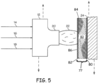
- FIG. 3A and FIG. 3B one aspect of the disclosed system for applying multi-layer and/or gradient composition coatings is depicted, that includes an atmospheric plasma device 12, one or more plasma-source gas streams 14, one or more precursor streams 16 and, optionally, one or more shielding gas streams 18.
- the output 20 of the atmospheric plasma device 12 is a mono-or multicomponent plasma 22, which can be horizontally or vertically positioned relative to substrate 24 to apply a multi-layer coating 26 onto substrate 24.
- Plasma 22 can be of any shape, for example, as shown in FIG. 3A , or as a point source, shower-head like pattern, or a divergent or convergent shape.
- the substrate 24 can be any substrate capable of receiving multi-layer coating by way of plasma 22.
- Substrate 24 can be metal or non-metal, where non-metal is inclusive of ceramics, plastics, polymers, composites of inorganic/organic materials, composites of polymers and inorganic/organic fibers.
- Substrate 24 can be conductive, nonconductive, or semi-conductive.
- the substrate 24 can be a transparent polymeric substrate, such as stretched acrylic.
- FIG. 3 shows a substrate 24 having a substantially flat configuration, those skilled in the art will appreciate that substrates 24 having various shapes, surface contour, sizes and configurations can be used without departing from the scope of the present disclosure.
- the atmospheric plasma device 12 can be any apparatus or system capable of exciting matter to form plasma 22, preferably under atmospheric conditions.
- the atmospheric plasma device 12 can be configured to generate the plasma 22 using direct current energy, radio frequency energy or the like, as is known in the art.
- the atmospheric plasma device 12 can be an atmospheric plasma spray gun.
- An atmospheric plasma device 12 useful in accordance with the present disclosure is the ATOMFLO TM 400 plasma system available from Surfx Technologies, LLC of Culver City, Calif.
- the plasma-source gas stream 14 can be a stream of one or more gaseous chemical precursors (reactive and/or nonreactive) capable of forming atmospheric plasma upon activation by the atmospheric plasma device 12.
- gaseous chemical precursors reactive and/or nonreactive
- appropriate plasma-forming gases include molecular compounds naturally occurring as a gas, such as oxygen gas (O 2 ), nitrogen gas (N 2 ), hydrogen gas (H 2 ) and fluorine gas (F 2 ), as well as other gases such as the noble gases (helium, neon, argon, krypton).
- the plasma-source gas stream 14 can also include specific combinations of gases.
- the plasma-source gas stream 14 can be a stream of substantially pure helium or argon gas that may allow the plasma to have a high concentration of active species while still maintaining a low temperature so as to deposit on temperature-sensitive polymers.
- the helium or argon gas may further contain one or more additional gases such as oxygen, nitrogen, carbon dioxide, hydrogen sulfide, ammonium, etc.
- the plasma-source gas stream 14 can be programmed for feeding the plasma device 12 for a time suitable to facilitate introduction of specific source gas streams combinations.
- the plasma-source gas stream 14 can be supplied to the atmospheric plasma device 12 at non-ambient conditions.
- the plasma-source gas stream 14 can be supplied to the atmospheric plasma device 12 at ambient conditions.
- the plasma-source gas stream 14 can be at a pressure of about 1 atm and a temperature of about 25 °C.
- physical conditions of the plasma-source gas stream 14 can vary depend upon the specific application and can be adjusted to optimize the performance of the atmospheric plasma device 12 depending on the nature of the source materials, the substrate, and/or the final thickness and/or final composition of the multi-layer coating desired.
- the precursor stream 16 can be one or more streams of the same or different precursor or precursors and, optionally, a carrier gas for introducing the precursor to the atmospheric plasma device 12.
- the carrier gas can be selected as a gas or combination of gases that does not undergo substantial plasma formation in the atmospheric plasma device 12. Examples of useful carrier gases include the noble gases, e.g., helium gas (He) and argon gas (Ar).
- the precursor can be any material capable of forming film or coating 26 when deposited onto a substrate 24 by way of the atmospheric plasma 22.
- the precursor can be a material capable of forming a silicon oxy-carbide (SiO x C y ) film or coating when deposited onto a substrate 24 by way of the atmospheric plasma 22.
- the precursor can be (or can include) a cyclic siloxane. Examples of precursors include tetramethylcyclocyclotetrasiloxane ("TMCTS”), octamethylcyclocyclotetrasiloxane (“OMCTS”), dimethyl siloxane (“DMSO”) and hexamethyldisiloxane (“HMDSO”).
- One or more monomers can be introduced alone or in combination with other chemical precursors into the atmospheric plasma to produce polymerized films.
- Organometallic compounds such as for example, diethyl zinc, tetra alkyl titanium compounds can be introduced alone or in combination with other chemical precursors into the atmospheric plasma to produce conductive, semi-conductive, or insulative films are coatings such as, 1,2-bis(triethoxysilyl)ethane (BTESE), tetra ethoxysilane (TEOS), hexamethyldisilazane (HMDSN) for providing wear resistant and/or abrasion resistant films; 3,4-ethylenedioxythiophene (EDOT), pyrrole-containing precursors to provide conductive polymer films; CHClF 2 (Chlorodifluoromethane) for providing hydrophobic films; indium (acac) 3 for providing indium tin oxide, mixed different zinc nit
- the precursor can be a relatively high vapor pressure liquid at standard temperature and pressure, and the carrier gas can be bubbled through the precursor to form the precursor stream 16.
- the carrier gas can be bubbled through the precursor to form the precursor stream 16.
- various alternative techniques such as vaporization, can be used to introduce one or more precursors to the precursor stream 16.
- the precursor stream 16 can be formed by bubbling helium gas through TMCTS liquid at ambient conditions.
- the shielding gas stream 18 can be a stream of shielding gas that does not undergo substantial plasma formation in the atmospheric plasma device 12.
- the shielding gas can be present in the plasma 22, but, without being limited to any particular theory, may minimize the effects of atmospheric water, oxygen and other contaminants on the plasma 22.
- appropriate shielding gases include the noble gases, e.g., helium gas (He) and argon gas (Ar).
- the shielding gas stream 18 may include combinations of shielding gases.
- the shielding gas stream 18 can be a stream of substantially pure helium gas.
- the shielding gas stream 18 can be supplied to the atmospheric plasma device 12 at non-ambient conditions.
- the shielding gas stream 14 can be supplied to the atmospheric plasma device 12 at ambient conditions.
- the shielding gas stream 14 can be at a pressure of about 1 atm and a temperature of about 25 °C.
- physical conditions of the shielding gas stream 14 may depend upon the specific application and can be adjusted to optimize the performance of the atmospheric plasma device 12.
- the plasma-source gas stream 14, the precursor stream 16 and the shielding gas stream 18 can be configured for introduction to the atmospheric plasma device 12 to form the plasma 22.
- two or more of the plasma-source gas, precursor and shielding gas streams 14, 16, 18 can be combined and/or mixed prior to reaching the atmospheric plasma device 12.
- the plasma-source gas, precursor, and shielding gas streams 14, 16, 18 can be supplied to the atmospheric plasma device 12 as a single stream.
- the flow rates of the plasma-source gas, precursor and shielding gas streams 14, 16, 18 can be controlled to obtain desired concentrations of the plasma-source gas, precursor and shielding gas in the plasma 22.
- control valves 10 can be provided on the plasma-source gas, precursor and shielding gas streams 14, 16, 18 to control the associated flow rates.
- the relative concentrations of the plasma-source gas, precursor and shielding gas in the plasma 22 can be manipulated to optimize performance of the atmospheric plasma device 12 and to impart the resulting coating 26 with desired properties.
- the concentration of oxygen in the plasma 22 can be decreased (e.g., by adjusting flow rate) to increase the carbon content of the coating 26, thereby yielding a base film or layer 26.
- the concentration of oxygen in the plasma 22 can be increased to render the layer more inorganic, thereby yielding a denser, e.g., harder layer (e.g., greater modulus than the underlying layer or film) as discussed below.
- the concentration of oxygen in the plasma 22 can be decreased to render the layer more organic with a lower modulus and more elasticity.
- the plasma-source gas stream 14 may comprise about 30 LPM of the input to the atmospheric plasma device 12 and the precursor stream 16 may comprise about 2-5 LPM of the input to the atmospheric plasma device 12, with the shielding gas stream 18 comprising the balance.
- the plasma-source gas stream 14 may comprise at most about 2 percent by volume of the input to the atmospheric plasma device 12 and the precursor stream 16 may comprise at most about 5 percent by volume of the input to the atmospheric plasma device 12, with the shielding gas stream 18 comprising the balance.
- the plasma-source gas stream 14 may comprise about 1 to 2 percent by volume of the input to the atmospheric plasma device 12 and the precursor stream 16 may comprise about 0 to about 10 percent by volume of the input to the atmospheric plasma device 12, with the shielding gas stream 18 comprising 0-100 percent by volume.
- a method for applying a multi-layer film coating 26 to a substrate 24, can begin with the step of cleaning the substrate, not shown.
- the substrate 24 can be cleaned using various solvents, such as ketones or light alcohols (e.g., methanol or isopropyl alcohol).
- a plasma may also be used to clean and/or activate the substrate 24.
- the presence of oxygen in the plasma may activate the surface receiving the multi-layer film coating 26.
- the clean substrate may optionally be treated with an adhesion promoter, such as an aluminum-based sol-gel adhesion promoter or silicon-based adhesion promoter, as is known in the art.
- the presently disclosed system can be configured by supplying the atmospheric plasma device 12 with the plasma-source gas, precursor and shielding gas streams 14, 16, 18 to form the plasma 22.
- the size (width or diameter) of the plasma 22 may depend on various factors, including the size of the atmospheric plasma device 12 and the flow rates of the plasma-source gas, precursor and shielding gas streams 14, 16, 18.
- the plasma 22 can be about 2 inches wide.
- the substrate 24 can be spatially coated by horizontally positioning the substrate 24 relative to the atmospheric plasma device 12 such that the plasma 22 deposits a first coating 26 onto the substrate.
- Plasma 22 can be translated along a direction essentially parallel to the surface of the substrate and/or raster scanned across the substrate 24 to deposit a second coating 27 on (or directly on) the surface of the substrate 24, the second coating being, for example, of different chemical composition or of a gradient composition than that of the first coating as shown by the dashed double arrows.
- the relationship between the first and the second coating can be random or can be a pattern presented in 2 dimensions e.g., the longitudinal axis of the deposited multi-layer film.
- a hand-held device can be used, those skilled in the art will appreciate that appropriate automation can be employed such that a multi-axis controlled unit is provided and/or maintained between and/or along the substrate 24 and the atmospheric plasma device 12.
- One or more additional coatings having continuous, semi-continuous, or stepped-like gradient chemical compositions can be deposited spatially over one or both of coatings 26, 27.
- Other coatings (non-plasma deposited) can be applied to the spatially separated coatings 26, 27 using any other appropriate coating methods (e.g., sol-gel).
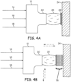
- FIGs. 4A and 4B an example multi-layer coating 75 is depicted, where the plasma device 12 is translated horizontally and/or vertically relative to the substrate surface as indicated by the pair of dashed double arrows. Combinations of the spatially separated aspects of FIGs. 3A and 3B and aspects of FIGs. 4A and 4B are envisioned.
- Multi-layer coating 77 is shown with the plurality of deposited films 80, 82, 83, 84, and 86 which can be deposited by adjustment of one or more process parameters including precursor source composition, precursor source composition and plasma-source gas composition, translation speed of substrate 24 alone or in combination with vertical adjustment of plasma device 12 as well as other process parameters or combination of the process parameters previously mentioned, for example as shown by dashed arrows representing translation of either plasma head 12 or substrate 24.
- Deposited films 80, 82, 83, 84 and 86 are representative of one or more of spatially separated deposited films and deposited films having chemical composition gradients in the vertical or horizontal direction relative to the substrate they are deposited upon.
- the methods disclosed herein may be used to provide a gradient multilayer film on the surface of an article.
- the surface of the article can be at least a portion of an aerospace vehicle.
- a first film can be provided within a second film or a plurality of films, one or more of the films (being the same or different chemical composition) having, independently, varying elemental compositions (one or more elements of the film's composition) in a multi-dimensional pattern, for example, by control of one or more of process parameters and/or plasma head translation and/or translation of the article (or substrate).
- Table 1 represents processing conditions for the preparation of spatially separated silicon oxy-carbide (SiOxCy) coatings on an aluminum substrate.
- the device was supplied with approximately 0.3-0.5 L/min oxygen gas, 1.0 L/min of TMCTS and/or HMDSO carried by helium gas, and 30 L/min helium gas (shielding gas).
- the TMCTS/helium stream was obtained by bubbling the helium gas carrier through a container of TMCTS liquid at ambient conditions. From the foregoing description, various modifications and changes in the compositions and method will occur to those skilled in the art. Table 1.
- Table 1 demonstrates modification of one or more of plasma power, carrier gas flow rate, precursor temperature, bubbler flow rate, or dilution flow rate, which will affect the composition of the one or more layers during deposition as shown in Table 2.
- Plasma head vertical position was held constant in these examples, relative to the substrate surface, but the vertical position of the plasma head can be varied as discussed above.
- Table 2 represents Auger Analysis performed on sample "G1" above in a first spatially separated area designated # 3. 1,000 ⁇ thick Ta 2 O 5 thickness standards were used to calibrate the argon ion sputtering rate. The calculated sputtering rate was 125 A/min. Change in carbon content measured by Auger electron spectroscopy and/or Scanning Electron Microscopy (SEM) and Energy Dispersive X-Ray (EDX) analysis (SEM-EDX) analysis methods indicated more carbon content near the bottom, demonstrating the gradation in the composition in at least one dimension. The top of the film has virtually no or trace amounts of carbon, creating a glassy, durable, harder film on top.
- SEM Auger electron spectroscopy
- EDX Energy Dispersive X-Ray
- a high concentration of carbon at the bottom of the film provides for improved adhesion to a polymeric substrate.
- Table 3 represents Auger Analysis performed on sample "G2," corresponding to a second sample that was deposited with a combination of TMCTS and HMDSO precursors. Table 3. Auger analysis of samples G2. Depth (angstroms) C (atomic %) Si (atomic %) O (atomic %) as-received 9.9 33.0 57.0 -100 Non-detected 42.1 57.9 -200 Non-detected 39.4 60.6 -300 Non-detected 40.5 59.5 -400 Non-detected 41.6 58.4 -500 12.3 36.6 51.1 -600 12.3 38.0 49.6 -700 6.6 39.1 54.3 -800 12.1 37.9 50.0 -900 11.0 39.4 49.6 -1,000 12.7 38.5 48.8 -1,500 8.9 40.0 51.1 -2,000 10.9 39.6 49.5 -2,500 12.8 38.1 49.1 -3,000 13.2 39.7 47.1 -3,500 16.1 36.7 47.1 -4,000 17.2 36.3 4
- a gradient film deposition wherein a thick base layer of a carbon-rich TMCTS film was deposited on top of a bare acrylic substrate.
- HMDSO a precursor that creates a harder, glassier, coating, was gradually introduced in order to grade (create a gradient) the chemical composition of the film over the film thickness. While not being held to any particular theory it is believed that the use of TMCTS near the polymer surface (initial plasma deposition process stage) creates a good adhesive layer, while use of HMDSO at the end of the plasma deposition process provides a durable, glassy "top surface” finish. Samples G-1, G-2, G-3, and G-4 are created in a similar fashion.
- BA8 and BA14 are single layerTMCTS films
- ML_17 is a multi-layer film of TMCTS that is made by varying only the plasma O 2 flow rate as a function of time.
- Samples G-1, G-2, G-3, and G-4 are much thinner than BA8, BA14, and ML_17, as seen in Figure 6 . As such, they would not be predicted to possess as much erosion resistance as the thicker single layer films.
- Surprisingly, however, as shown in Figure 7 several of these presently prepared gradient films actually perform better under Taber abrasion than single layer TMCTS films, which is believed due to the harder, SiO 2 -like layer on top that is created with the HMDSO precursor in the final stages of the plasma deposition. Change in haze after falling sand testing for the single and multi-layer films presented in Figure 7 shows similar unexpected results for the multi-layer films in comparison with the thicker single layer films
- the substrate can be polymer or non-polymer
- a stack of films were deposited on a bare poly methyl methacrylate (PMMA) substrate to provide a 2-4 micron thick layer film made from the plasma deposition of TMCTS precursor.
- PMMA poly methyl methacrylate
- TMCTS-plasma-films have been determined to have relatively low elastic modulus (around 10 GPa) that adheres well onto PMMA. As a result, TMCTS-plasma-film performs well under wet and dry adhesion testing, but may not be as durable as plasma-deposited films with a higher modulus.
- the present method employs, by way of example, the deposition on (or directly on) of a second film made from plasma-deposited OMCTS precursor and/or another precursor with deposited film a modulus of greater than 10 GPa, e.g., about 15-20 GPa as measured by nanoindentation techniques (Nanoindenter XP; Agilent Technologies).
- the second film can be less than 1 micron thick.
- a top layer of a hard film e.g., with a modulus of greater than 20 GPa, with a thickness around 500 nm, can be deposited on (or directly on) the second layer.
- Suitable functionalities obtainable by the presently disclosed method includes, without limitation, erosion and/or abrasion resistance, conductivity (electrical and/or thermal), optical properties (haze or clarity), radiation absorption and/or reflection (IR, microwave, etc.) or combinations ("multifunctionality").
- FIG. 8 provides process parameters and physical properties of additional samples of gradient multi-layer films prepared from OMCTS precursor gas streams with varying process parameters to provide a chemical gradient throughout the horizontal thickness of the film relative to the substrate surface, TMCTS precursor gas streams with varying process parameters, and combinations of same.
- optimization of substrate-enhanced properties e.g., clarity, haze, and Taber abrasion can be provided.
- the resistance to both erosion and abrasion while optimizing adhesion throughout the entire film can be provided with the selection of TMCTS-OMCTS deposited in a sequential manner.
- multi-layer stacks made for example with atmospheric plasma deposition can be used to incorporate other multifunctionality into the surface.
- semiconductive zinc oxide (ZnO) films can be deposited using atmospheric plasma deposition (ZnO-plasma-films) to provide a durable silicon-oxy-carbide coating.
- ZnO or other conductive films can be deposited on substrates such as polycarbonate or carbon fiber reinforced polymers (CFRP) for improving static dissipation of charge buildup.
- Multi-layer films having conductive (electrical) properties can be combined with a dielectric, protective plasma deposited film.
- a conductive ZnO-plasma-film can be deposited in accordance with the present disclosure and this deposited film can be protected, for example, using the durable film stack of TMCTS-OMCTS as described above, e.g., by depositing on or directly on the top.
- Other possible multifunctional films include infrared rejecting/deflecting films to reduce heat load encompassed by a durable layer or energy harvesting films incorporated with a durable film stack as described above.
- the plasma head 12 can be adapted to an articulated arm of a robotic system that is coupled to one or more controllers and/or centralized control system to provide at least two-axes translation of the plasma head for the deposition of the multi-layer or gradient films.
- the substrate or article can be configured to be translated in multi-axial directions during deposition. Both the plasma head and article/substrate can be configured for multi-axial translation.
- the gradient film deposition process is presently disclosed can be totally automated so as to provide gradient films that vary spatially in their mechanical properties, for example, by slightly changing the deposition conditions as the plasma head scans over the substrate surface.
- One or more parameters that have been found to affect mechanical properties of the presently disclosed multi-gradient films include oxygen flow rate, helium flow rate through the chemical, plasma head speed, and plasma power. These parameters can be programmed to vary as the plasma head scans across a surface in order to deposit spatially gradient films for can be manually controlled during a deposition process.
- an example where this type of process can be used is as follows: if a certain part of a substrate will be covered with a sealant, the appropriate mechanical properties of the spatially gradient film will be different depending on the composition of the substrate.
Landscapes
- Chemical & Material Sciences (AREA)
- Engineering & Computer Science (AREA)
- General Chemical & Material Sciences (AREA)
- Chemical Kinetics & Catalysis (AREA)
- Materials Engineering (AREA)
- Mechanical Engineering (AREA)
- Metallurgy (AREA)
- Organic Chemistry (AREA)
- Physics & Mathematics (AREA)
- Plasma & Fusion (AREA)
- Inorganic Chemistry (AREA)
- Chemical Vapour Deposition (AREA)
Applications Claiming Priority (2)
| Application Number | Priority Date | Filing Date | Title |
|---|---|---|---|
| US14/104,796 US9139908B2 (en) | 2013-12-12 | 2013-12-12 | Gradient thin films |
| PCT/US2014/056467 WO2015088613A1 (en) | 2013-12-12 | 2014-09-19 | Gradient thin films |
Publications (2)
| Publication Number | Publication Date |
|---|---|
| EP3080331A1 EP3080331A1 (en) | 2016-10-19 |
| EP3080331B1 true EP3080331B1 (en) | 2024-12-18 |
Family
ID=51660657
Family Applications (1)
| Application Number | Title | Priority Date | Filing Date |
|---|---|---|---|
| EP14780989.1A Active EP3080331B1 (en) | 2013-12-12 | 2014-09-19 | Gradient thin films |
Country Status (8)
| Country | Link |
|---|---|
| US (1) | US9139908B2 (enExample) |
| EP (1) | EP3080331B1 (enExample) |
| JP (1) | JP6381649B2 (enExample) |
| KR (1) | KR102374881B1 (enExample) |
| CN (1) | CN105723013B (enExample) |
| AU (1) | AU2014360781B2 (enExample) |
| RU (1) | RU2666198C1 (enExample) |
| WO (1) | WO2015088613A1 (enExample) |
Families Citing this family (17)
| Publication number | Priority date | Publication date | Assignee | Title |
|---|---|---|---|---|
| US9869013B2 (en) * | 2014-04-25 | 2018-01-16 | Applied Materials, Inc. | Ion assisted deposition top coat of rare-earth oxide |
| WO2018130289A1 (en) * | 2017-01-12 | 2018-07-19 | Applied Materials, Inc. | Hardcoat layer system and method for manufacturing a hardcoat layer system in a continuous roll-to-roll process |
| US10985344B2 (en) | 2017-10-27 | 2021-04-20 | Applied Materials, Inc. | Flexible cover lens films |
| JP7716853B2 (ja) | 2018-05-10 | 2025-08-01 | アプライド マテリアルズ インコーポレイテッド | フレキシブルディスプレイ用の交換可能なカバーレンズ |
| WO2020036693A1 (en) | 2018-08-14 | 2020-02-20 | Applied Materials, Inc. | Multi-layer wet-dry hardcoats for flexible cover lens |
| RU2702881C1 (ru) * | 2018-09-28 | 2019-10-11 | Общество с ограниченной ответственностью "Научно-производственное объединение "Защитные покрытия", ООО "НПО "Защитные покрытия" | Градиентное металлополимерное покрытие |
| CN113227909B (zh) | 2018-12-20 | 2025-07-04 | 朗姆研究公司 | 抗蚀剂的干式显影 |
| KR102780681B1 (ko) | 2019-06-26 | 2025-03-11 | 어플라이드 머티어리얼스, 인코포레이티드 | 폴더블 디스플레이들을 위한 플렉서블 다층 커버 렌즈 스택들 |
| TWI869221B (zh) | 2019-06-26 | 2025-01-01 | 美商蘭姆研究公司 | 利用鹵化物化學品的光阻顯影 |
| JP7618601B2 (ja) * | 2019-06-28 | 2025-01-21 | ラム リサーチ コーポレーション | 複数のパターニング放射吸収元素および/または垂直組成勾配を備えたフォトレジスト |
| US20240117495A1 (en) * | 2019-10-14 | 2024-04-11 | Silcotek Corp. | Cold thermal chemical vapor deposition |
| KR20250007037A (ko) | 2020-01-15 | 2025-01-13 | 램 리써치 코포레이션 | 포토레지스트 부착 및 선량 감소를 위한 하부층 |
| CN116626993A (zh) | 2020-07-07 | 2023-08-22 | 朗姆研究公司 | 用于图案化辐射光致抗蚀剂图案化的集成干燥工艺 |
| JP7562696B2 (ja) | 2020-11-13 | 2024-10-07 | ラム リサーチ コーポレーション | フォトレジストのドライ除去用プロセスツール |
| DE102022105041A1 (de) * | 2022-03-03 | 2023-09-07 | IonKraft GmbH | Beschichtungstechnik für Kunststoffbehälter |
| BR102022012045A2 (pt) * | 2022-06-17 | 2024-01-02 | Autocoat Equipamentos E Processos De Deposição Ltda | Dispositivo para deposição de filmes finos por lâmina e processo derivado |
| CN117004920A (zh) * | 2023-07-28 | 2023-11-07 | 上海大学 | 一种梯度h-BNC纳米自清洁薄膜设计方法 |
Citations (3)
| Publication number | Priority date | Publication date | Assignee | Title |
|---|---|---|---|---|
| US20060210783A1 (en) * | 2005-03-18 | 2006-09-21 | Seder Thomas A | Coated article with anti-reflective coating and method of making same |
| US20080233366A1 (en) * | 2007-03-23 | 2008-09-25 | International Business Machines Corporation | STRUCTURE AND METHOD FOR SiCOH INTERFACES WITH INCREASED MECHANICAL STRENGTH |
| WO2013192547A1 (en) * | 2012-06-23 | 2013-12-27 | Frito-Lay North America, Inc. | Deposition of ultra-thin inorganic oxide coatings on packaging |
Family Cites Families (50)
| Publication number | Priority date | Publication date | Assignee | Title |
|---|---|---|---|---|
| GB1051393A (enExample) | 1964-08-28 | 1900-01-01 | ||
| US4414085A (en) * | 1981-10-08 | 1983-11-08 | Wickersham Charles E | Method of depositing a high-emissivity layer |
| DE3706340A1 (de) * | 1987-02-27 | 1988-09-08 | Winter & Sohn Ernst | Verfahren zum auftragen einer verschleissschutzschicht und danach hergestelltes erzeugnis |
| US5482602A (en) * | 1993-11-04 | 1996-01-09 | United Technologies Corporation | Broad-beam ion deposition coating methods for depositing diamond-like-carbon coatings on dynamic surfaces |
| DE4445427C2 (de) * | 1994-12-20 | 1997-04-30 | Schott Glaswerke | Plasma-CVD-Verfahren zur Herstellung einer Gradientenschicht |
| RU2189663C2 (ru) * | 1997-06-30 | 2002-09-20 | Мацушита Электрик Индастриал Ко., Лтд. | Способ и устройство для изготовления тонкой полупроводниковой пленки |
| US5926740A (en) * | 1997-10-27 | 1999-07-20 | Micron Technology, Inc. | Graded anti-reflective coating for IC lithography |
| JPH11124693A (ja) | 1997-10-20 | 1999-05-11 | Nippon Steel Corp | 精密機器用部材 |
| JP3782608B2 (ja) | 1998-05-22 | 2006-06-07 | キヤノン株式会社 | 薄膜材料および薄膜作成法 |
| JP2000256850A (ja) * | 1999-03-04 | 2000-09-19 | Riken Corp | ダイヤモンドライクカーボン薄膜及びその製造方法 |
| US6221737B1 (en) | 1999-09-30 | 2001-04-24 | Philips Electronics North America Corporation | Method of making semiconductor devices with graded top oxide and graded drift region |
| AU4901201A (en) | 1999-10-25 | 2001-07-03 | Rolls-Royce Corporation | Erosion-resistant coatings for organic matric composites |
| US20050268962A1 (en) | 2000-04-27 | 2005-12-08 | Russell Gaudiana | Flexible Photovoltaic cells, systems and methods |
| US20050257827A1 (en) | 2000-04-27 | 2005-11-24 | Russell Gaudiana | Rotational photovoltaic cells, systems and methods |
| US6962751B2 (en) * | 2001-06-13 | 2005-11-08 | Sumitomo Electric Industries, Ltd. | Amorphous carbon coated tools and method of producing the same |
| US6881475B2 (en) * | 2001-06-13 | 2005-04-19 | Sumitomo Electric Industries, Ltd | Amorphous carbon coated tool and fabrication method thereof |
| JP4151000B2 (ja) * | 2002-06-13 | 2008-09-17 | 株式会社オンワード技研 | ワークの表面処理方法と、その装置 |
| US6852920B2 (en) | 2002-06-22 | 2005-02-08 | Nanosolar, Inc. | Nano-architected/assembled solar electricity cell |
| US7713592B2 (en) * | 2003-02-04 | 2010-05-11 | Tegal Corporation | Nanolayer deposition process |
| US20050118502A1 (en) | 2003-11-27 | 2005-06-02 | Matsushita Electric Industrial Co., Ltd. | Energy device and method for producing the same |
| US20090026587A1 (en) * | 2004-01-14 | 2009-01-29 | International Business Machines Corporation | Gradient deposition of low-k cvd materials |
| KR20070037492A (ko) * | 2004-06-15 | 2007-04-04 | 에비자 테크놀로지, 인크. | 다성분 유전체 필름을 형성하기 위한 시스템 및 방법 |
| US7637967B2 (en) | 2005-12-08 | 2009-12-29 | Siemens Energy, Inc. | Stepped gradient fuel electrode and method for making the same |
| US7700167B2 (en) | 2006-08-31 | 2010-04-20 | Honeywell International Inc. | Erosion-protective coatings on polymer-matrix composites and components incorporating such coated composites |
| WO2008114627A1 (ja) * | 2007-03-16 | 2008-09-25 | Konica Minolta Holdings, Inc. | 防汚性積層体及びディスプレイ用前面板 |
| JP5407869B2 (ja) * | 2007-11-19 | 2014-02-05 | コニカミノルタ株式会社 | 撥水または防汚性物品、それを用いて構成された建築用窓ガラス、車両用窓ガラス、ディスプレイ部材、光学部品 |
| US20090301550A1 (en) | 2007-12-07 | 2009-12-10 | Sunprint Inc. | Focused acoustic printing of patterned photovoltaic materials |
| US8099792B1 (en) | 2008-01-07 | 2012-01-17 | Northwestern University | Methods and apparatus for spatially resolved photocurrent mapping of operating photovoltaic devices using atomic force photovoltaic microscopy |
| WO2009094663A2 (en) | 2008-01-25 | 2009-07-30 | University Of Washington | Photovoltaic devices having metal oxide electron-transport layers |
| US20090229667A1 (en) | 2008-03-14 | 2009-09-17 | Solarmer Energy, Inc. | Translucent solar cell |
| FR2931844B1 (fr) | 2008-06-02 | 2013-11-01 | Alex Hr Roustaei | Systemes pour la production de l'energie a la demande comme une source seule ou en assistance avec autres sources d'energie dans le domaine du transport ou de l'habitat. |
| DE102008028540A1 (de) * | 2008-06-16 | 2009-12-17 | Fraunhofer-Gesellschaft zur Förderung der angewandten Forschung e.V. | Verfahren zum Abscheiden einer Gradientenschicht auf einem Kunststoffsubstrat sowie Kunststoffsubstrat mit einer Gradientenschicht |
| DE102008033938B4 (de) | 2008-07-18 | 2012-04-19 | Innovent E.V. | Verfahren zur Abscheidung von Schichten auf einem Substrat |
| US20110253217A1 (en) | 2008-09-30 | 2011-10-20 | The Regents Of The University Of California | Controlled Alignment in Polymeric Solar Cells |
| US8269100B2 (en) | 2008-09-30 | 2012-09-18 | Uchicago Argonne, Llc | Hybrid solar cells via UV-polymerization of polymer precursor |
| KR20110094279A (ko) | 2008-10-31 | 2011-08-23 | 바스프 에스이 | 유기 태양 전지용 및 유기 광검출기용 광활성 층 제조를 위한 메로시아닌 |
| DE102008060923B4 (de) | 2008-12-06 | 2012-09-27 | Innovent E.V. | Verwendung einer Schicht |
| FR2956869B1 (fr) | 2010-03-01 | 2014-05-16 | Alex Hr Roustaei | Systeme de production de film flexible a haute capacite destine a des cellules photovoltaiques et oled par deposition cyclique des couches |
| JP2012519965A (ja) | 2009-03-06 | 2012-08-30 | ユニバーシティ オブ フロリダ リサーチ ファウンデーション,インク. | 空気安定性有機−無機ナノ粒子ハイブリッド太陽電池 |
| JP5222764B2 (ja) * | 2009-03-24 | 2013-06-26 | 株式会社神戸製鋼所 | 積層皮膜および積層皮膜被覆部材 |
| US8206794B2 (en) * | 2009-05-04 | 2012-06-26 | The Boeing Company | System and method for applying abrasion-resistant coatings |
| CN101560653A (zh) * | 2009-05-14 | 2009-10-21 | 浙江大学 | 梯度折射率薄膜的制备方法 |
| US20110030770A1 (en) | 2009-08-04 | 2011-02-10 | Molecular Imprints, Inc. | Nanostructured organic solar cells |
| EP2462254A1 (en) * | 2009-08-07 | 2012-06-13 | Oerlikon Trading AG, Trübbach | Tribology combined with corrosion resistance: a new family of pvd- and pacvd coatings |
| WO2011045253A1 (de) | 2009-10-13 | 2011-04-21 | Basf Se | Mischungen zur herstellung von photoaktiven schichten für organische solarzellen und organische photodetektoren |
| US8871884B2 (en) | 2009-10-28 | 2014-10-28 | University Of Washington | Copolymer semiconductors comprising thiazolothiazole or benzobisthiazole, or benzobisoxazole electron acceptor subunits, and electron donor subunits, and their uses in transistors and solar cells |
| WO2012031083A2 (en) | 2010-09-01 | 2012-03-08 | Iowa State University Research Foundation, Inc. | Textured micrometer scale templates as light managing fabrication platform for organic solar cells |
| US20120024380A1 (en) | 2010-10-27 | 2012-02-02 | Primestar Solar, Inc. | Intermixing of cadmium sulfide layers and cadmium telluride layers for thin film photovoltaic devices and methods of their manufacture |
| EP2647050B1 (en) | 2010-12-03 | 2018-04-11 | Novaled GmbH | Method for forming an electrical interconnection in an organic photovoltaic device and an organic photovoltaic device made by the same |
| JP5595897B2 (ja) * | 2010-12-24 | 2014-09-24 | 小島プレス工業株式会社 | 樹脂製品の製造方法 |
-
2013
- 2013-12-12 US US14/104,796 patent/US9139908B2/en active Active
-
2014
- 2014-09-19 KR KR1020167009588A patent/KR102374881B1/ko active Active
- 2014-09-19 AU AU2014360781A patent/AU2014360781B2/en active Active
- 2014-09-19 RU RU2016111166A patent/RU2666198C1/ru active
- 2014-09-19 JP JP2016538729A patent/JP6381649B2/ja active Active
- 2014-09-19 EP EP14780989.1A patent/EP3080331B1/en active Active
- 2014-09-19 CN CN201480062243.6A patent/CN105723013B/zh active Active
- 2014-09-19 WO PCT/US2014/056467 patent/WO2015088613A1/en not_active Ceased
Patent Citations (3)
| Publication number | Priority date | Publication date | Assignee | Title |
|---|---|---|---|---|
| US20060210783A1 (en) * | 2005-03-18 | 2006-09-21 | Seder Thomas A | Coated article with anti-reflective coating and method of making same |
| US20080233366A1 (en) * | 2007-03-23 | 2008-09-25 | International Business Machines Corporation | STRUCTURE AND METHOD FOR SiCOH INTERFACES WITH INCREASED MECHANICAL STRENGTH |
| WO2013192547A1 (en) * | 2012-06-23 | 2013-12-27 | Frito-Lay North America, Inc. | Deposition of ultra-thin inorganic oxide coatings on packaging |
Also Published As
| Publication number | Publication date |
|---|---|
| CN105723013B (zh) | 2018-01-16 |
| KR20160098165A (ko) | 2016-08-18 |
| CN105723013A (zh) | 2016-06-29 |
| WO2015088613A1 (en) | 2015-06-18 |
| RU2666198C1 (ru) | 2018-09-06 |
| JP2017500448A (ja) | 2017-01-05 |
| KR102374881B1 (ko) | 2022-03-15 |
| EP3080331A1 (en) | 2016-10-19 |
| AU2014360781A1 (en) | 2016-04-21 |
| US20150167170A1 (en) | 2015-06-18 |
| AU2014360781B2 (en) | 2018-04-12 |
| JP6381649B2 (ja) | 2018-08-29 |
| US9139908B2 (en) | 2015-09-22 |
Similar Documents
| Publication | Publication Date | Title |
|---|---|---|
| EP3080331B1 (en) | Gradient thin films | |
| US8932737B2 (en) | Durable UV blocking transparent coating | |
| US20080241523A1 (en) | Substrate, Such As A Glass Substrate, With A Hydrophobic Surface And Improved Durability Of Hydrophobic Properties | |
| JP5716663B2 (ja) | 防汚性積層体 | |
| CN105556698A (zh) | 用于高性能涂层的沉积的方法以及封装的电子器件 | |
| CN101233259A (zh) | 沉积耐刮擦膜的方法 | |
| TWI424185B (zh) | 抗反射板及其抗反射結構之製造方法 | |
| WO2006063388A1 (en) | Craze resistant plastic article and method of production | |
| CN101023499A (zh) | 透明导电膜 | |
| US8206794B2 (en) | System and method for applying abrasion-resistant coatings | |
| US20090311539A1 (en) | Wear-resistant coating for polymeric transparencies | |
| JPWO2007142059A1 (ja) | ガスバリア膜付きプラスチック製光学素子およびその製造方法とこれを適用した光ピックアップ装置 | |
| TWI432595B (zh) | 基板塗層及其形成方法 | |
| TWI668320B (zh) | 提高抗汙膜之附著力的方法 | |
| US10118195B2 (en) | Methods for depositing a transparent thin film onto substrates using an atmospheric plasma generating device | |
| US20110086235A1 (en) | Methods of nucleation control in film deposition | |
| Choi et al. | Scratch-resistant hydrophobic and oleophobic coatings prepared by simple PECVD method | |
| GB2518358A (en) | Glass preforms for molding and a method of molding glass articles | |
| US20250137113A1 (en) | Coated articles with a planarization layer/hydroxyl-modified layer and a surface-modifying layer and methods of making the same | |
| CN120233472A (zh) | 玻璃显示面板防护膜、其制备方法以及包括其的产品 | |
| Frach et al. | Advanced key technologies for magnetron sputtering and PECVD of inorganic and hybrid transparent coatings | |
| CN119980180A (zh) | 在玻璃表面制备类金刚石保护膜的制备方法、类金刚石保护膜及玻璃 | |
| JPH0990102A (ja) | 被膜を備えた光学物品およびその製造方法 | |
| CN119630832A (zh) | 装饰性涂覆的聚合物基材及其获得方法 | |
| CN116802165A (zh) | 近红外透明、可见光吸收涂层及具有涂层的玻璃基板 |
Legal Events
| Date | Code | Title | Description |
|---|---|---|---|
| PUAI | Public reference made under article 153(3) epc to a published international application that has entered the european phase |
Free format text: ORIGINAL CODE: 0009012 |
|
| 17P | Request for examination filed |
Effective date: 20160523 |
|
| AK | Designated contracting states |
Kind code of ref document: A1 Designated state(s): AL AT BE BG CH CY CZ DE DK EE ES FI FR GB GR HR HU IE IS IT LI LT LU LV MC MK MT NL NO PL PT RO RS SE SI SK SM TR |
|
| AX | Request for extension of the european patent |
Extension state: BA ME |
|
| DAX | Request for extension of the european patent (deleted) | ||
| STAA | Information on the status of an ep patent application or granted ep patent |
Free format text: STATUS: EXAMINATION IS IN PROGRESS |
|
| 17Q | First examination report despatched |
Effective date: 20170720 |
|
| RAP3 | Party data changed (applicant data changed or rights of an application transferred) |
Owner name: THE BOEING COMPANY |
|
| REG | Reference to a national code |
Ref country code: DE Free format text: PREVIOUS MAIN CLASS: C23C0016453000 Ref country code: DE Ref legal event code: R079 Ref document number: 602014091350 Country of ref document: DE Free format text: PREVIOUS MAIN CLASS: C23C0016453000 Ipc: C23C0016400000 |
|
| GRAP | Despatch of communication of intention to grant a patent |
Free format text: ORIGINAL CODE: EPIDOSNIGR1 |
|
| STAA | Information on the status of an ep patent application or granted ep patent |
Free format text: STATUS: GRANT OF PATENT IS INTENDED |
|
| RIC1 | Information provided on ipc code assigned before grant |
Ipc: C23C 16/04 20060101ALI20231214BHEP Ipc: C23C 16/40 20060101AFI20231214BHEP |
|
| INTG | Intention to grant announced |
Effective date: 20240124 |
|
| RIN1 | Information on inventor provided before grant (corrected) |
Inventor name: MATOS, MARVI A. Inventor name: RANADE, ALPANA |
|
| GRAJ | Information related to disapproval of communication of intention to grant by the applicant or resumption of examination proceedings by the epo deleted |
Free format text: ORIGINAL CODE: EPIDOSDIGR1 |
|
| STAA | Information on the status of an ep patent application or granted ep patent |
Free format text: STATUS: EXAMINATION IS IN PROGRESS |
|
| INTC | Intention to grant announced (deleted) | ||
| GRAP | Despatch of communication of intention to grant a patent |
Free format text: ORIGINAL CODE: EPIDOSNIGR1 |
|
| STAA | Information on the status of an ep patent application or granted ep patent |
Free format text: STATUS: GRANT OF PATENT IS INTENDED |
|
| INTG | Intention to grant announced |
Effective date: 20240619 |
|
| P01 | Opt-out of the competence of the unified patent court (upc) registered |
Free format text: CASE NUMBER: APP_42795/2024 Effective date: 20240721 |
|
| GRAS | Grant fee paid |
Free format text: ORIGINAL CODE: EPIDOSNIGR3 |
|
| GRAA | (expected) grant |
Free format text: ORIGINAL CODE: 0009210 |
|
| STAA | Information on the status of an ep patent application or granted ep patent |
Free format text: STATUS: THE PATENT HAS BEEN GRANTED |
|
| AK | Designated contracting states |
Kind code of ref document: B1 Designated state(s): AL AT BE BG CH CY CZ DE DK EE ES FI FR GB GR HR HU IE IS IT LI LT LU LV MC MK MT NL NO PL PT RO RS SE SI SK SM TR |
|
| REG | Reference to a national code |
Ref country code: GB Ref legal event code: FG4D |
|
| REG | Reference to a national code |
Ref country code: CH Ref legal event code: EP |
|
| REG | Reference to a national code |
Ref country code: DE Ref legal event code: R096 Ref document number: 602014091350 Country of ref document: DE |
|
| REG | Reference to a national code |
Ref country code: IE Ref legal event code: FG4D |
|
| REG | Reference to a national code |
Ref country code: LT Ref legal event code: MG9D |
|
| PG25 | Lapsed in a contracting state [announced via postgrant information from national office to epo] |
Ref country code: HR Free format text: LAPSE BECAUSE OF FAILURE TO SUBMIT A TRANSLATION OF THE DESCRIPTION OR TO PAY THE FEE WITHIN THE PRESCRIBED TIME-LIMIT Effective date: 20241218 |
|
| PG25 | Lapsed in a contracting state [announced via postgrant information from national office to epo] |
Ref country code: FI Free format text: LAPSE BECAUSE OF FAILURE TO SUBMIT A TRANSLATION OF THE DESCRIPTION OR TO PAY THE FEE WITHIN THE PRESCRIBED TIME-LIMIT Effective date: 20241218 |
|
| PG25 | Lapsed in a contracting state [announced via postgrant information from national office to epo] |
Ref country code: BG Free format text: LAPSE BECAUSE OF FAILURE TO SUBMIT A TRANSLATION OF THE DESCRIPTION OR TO PAY THE FEE WITHIN THE PRESCRIBED TIME-LIMIT Effective date: 20241218 |
|
| PG25 | Lapsed in a contracting state [announced via postgrant information from national office to epo] |
Ref country code: NO Free format text: LAPSE BECAUSE OF FAILURE TO SUBMIT A TRANSLATION OF THE DESCRIPTION OR TO PAY THE FEE WITHIN THE PRESCRIBED TIME-LIMIT Effective date: 20250318 |
|
| REG | Reference to a national code |
Ref country code: NL Ref legal event code: MP Effective date: 20241218 |
|
| PG25 | Lapsed in a contracting state [announced via postgrant information from national office to epo] |
Ref country code: GR Free format text: LAPSE BECAUSE OF FAILURE TO SUBMIT A TRANSLATION OF THE DESCRIPTION OR TO PAY THE FEE WITHIN THE PRESCRIBED TIME-LIMIT Effective date: 20250319 Ref country code: LV Free format text: LAPSE BECAUSE OF FAILURE TO SUBMIT A TRANSLATION OF THE DESCRIPTION OR TO PAY THE FEE WITHIN THE PRESCRIBED TIME-LIMIT Effective date: 20241218 |
|
| PG25 | Lapsed in a contracting state [announced via postgrant information from national office to epo] |
Ref country code: RS Free format text: LAPSE BECAUSE OF FAILURE TO SUBMIT A TRANSLATION OF THE DESCRIPTION OR TO PAY THE FEE WITHIN THE PRESCRIBED TIME-LIMIT Effective date: 20250318 |
|
| PG25 | Lapsed in a contracting state [announced via postgrant information from national office to epo] |
Ref country code: NL Free format text: LAPSE BECAUSE OF FAILURE TO SUBMIT A TRANSLATION OF THE DESCRIPTION OR TO PAY THE FEE WITHIN THE PRESCRIBED TIME-LIMIT Effective date: 20241218 |
|
| REG | Reference to a national code |
Ref country code: AT Ref legal event code: MK05 Ref document number: 1752302 Country of ref document: AT Kind code of ref document: T Effective date: 20241218 |
|
| PG25 | Lapsed in a contracting state [announced via postgrant information from national office to epo] |
Ref country code: SM Free format text: LAPSE BECAUSE OF FAILURE TO SUBMIT A TRANSLATION OF THE DESCRIPTION OR TO PAY THE FEE WITHIN THE PRESCRIBED TIME-LIMIT Effective date: 20241218 |
|
| PG25 | Lapsed in a contracting state [announced via postgrant information from national office to epo] |
Ref country code: PL Free format text: LAPSE BECAUSE OF FAILURE TO SUBMIT A TRANSLATION OF THE DESCRIPTION OR TO PAY THE FEE WITHIN THE PRESCRIBED TIME-LIMIT Effective date: 20241218 |
|
| PG25 | Lapsed in a contracting state [announced via postgrant information from national office to epo] |
Ref country code: ES Free format text: LAPSE BECAUSE OF FAILURE TO SUBMIT A TRANSLATION OF THE DESCRIPTION OR TO PAY THE FEE WITHIN THE PRESCRIBED TIME-LIMIT Effective date: 20241218 |
|
| PG25 | Lapsed in a contracting state [announced via postgrant information from national office to epo] |
Ref country code: IS Free format text: LAPSE BECAUSE OF FAILURE TO SUBMIT A TRANSLATION OF THE DESCRIPTION OR TO PAY THE FEE WITHIN THE PRESCRIBED TIME-LIMIT Effective date: 20250418 |
|
| PG25 | Lapsed in a contracting state [announced via postgrant information from national office to epo] |
Ref country code: PT Free format text: LAPSE BECAUSE OF FAILURE TO SUBMIT A TRANSLATION OF THE DESCRIPTION OR TO PAY THE FEE WITHIN THE PRESCRIBED TIME-LIMIT Effective date: 20250421 |
|
| PG25 | Lapsed in a contracting state [announced via postgrant information from national office to epo] |
Ref country code: EE Free format text: LAPSE BECAUSE OF FAILURE TO SUBMIT A TRANSLATION OF THE DESCRIPTION OR TO PAY THE FEE WITHIN THE PRESCRIBED TIME-LIMIT Effective date: 20241218 |
|
| PG25 | Lapsed in a contracting state [announced via postgrant information from national office to epo] |
Ref country code: AT Free format text: LAPSE BECAUSE OF FAILURE TO SUBMIT A TRANSLATION OF THE DESCRIPTION OR TO PAY THE FEE WITHIN THE PRESCRIBED TIME-LIMIT Effective date: 20241218 Ref country code: RO Free format text: LAPSE BECAUSE OF FAILURE TO SUBMIT A TRANSLATION OF THE DESCRIPTION OR TO PAY THE FEE WITHIN THE PRESCRIBED TIME-LIMIT Effective date: 20241218 |
|
| PG25 | Lapsed in a contracting state [announced via postgrant information from national office to epo] |
Ref country code: SK Free format text: LAPSE BECAUSE OF FAILURE TO SUBMIT A TRANSLATION OF THE DESCRIPTION OR TO PAY THE FEE WITHIN THE PRESCRIBED TIME-LIMIT Effective date: 20241218 |
|
| PG25 | Lapsed in a contracting state [announced via postgrant information from national office to epo] |
Ref country code: CZ Free format text: LAPSE BECAUSE OF FAILURE TO SUBMIT A TRANSLATION OF THE DESCRIPTION OR TO PAY THE FEE WITHIN THE PRESCRIBED TIME-LIMIT Effective date: 20241218 |
|
| PG25 | Lapsed in a contracting state [announced via postgrant information from national office to epo] |
Ref country code: IT Free format text: LAPSE BECAUSE OF FAILURE TO SUBMIT A TRANSLATION OF THE DESCRIPTION OR TO PAY THE FEE WITHIN THE PRESCRIBED TIME-LIMIT Effective date: 20241218 |
|
| PG25 | Lapsed in a contracting state [announced via postgrant information from national office to epo] |
Ref country code: SE Free format text: LAPSE BECAUSE OF FAILURE TO SUBMIT A TRANSLATION OF THE DESCRIPTION OR TO PAY THE FEE WITHIN THE PRESCRIBED TIME-LIMIT Effective date: 20241218 |
|
| REG | Reference to a national code |
Ref country code: DE Ref legal event code: R097 Ref document number: 602014091350 Country of ref document: DE |
|
| PG25 | Lapsed in a contracting state [announced via postgrant information from national office to epo] |
Ref country code: DK Free format text: LAPSE BECAUSE OF FAILURE TO SUBMIT A TRANSLATION OF THE DESCRIPTION OR TO PAY THE FEE WITHIN THE PRESCRIBED TIME-LIMIT Effective date: 20241218 |
|
| PGFP | Annual fee paid to national office [announced via postgrant information from national office to epo] |
Ref country code: DE Payment date: 20250929 Year of fee payment: 12 |
|
| PGFP | Annual fee paid to national office [announced via postgrant information from national office to epo] |
Ref country code: GB Payment date: 20250929 Year of fee payment: 12 |
|
| PGFP | Annual fee paid to national office [announced via postgrant information from national office to epo] |
Ref country code: FR Payment date: 20250925 Year of fee payment: 12 |
|
| PLBE | No opposition filed within time limit |
Free format text: ORIGINAL CODE: 0009261 |
|
| STAA | Information on the status of an ep patent application or granted ep patent |
Free format text: STATUS: NO OPPOSITION FILED WITHIN TIME LIMIT |
|
| 26N | No opposition filed |
Effective date: 20250919 |