EP3079593B1 - Scanning x-ray imaging device with variable shield plates and method for operating same - Google Patents
Scanning x-ray imaging device with variable shield plates and method for operating same Download PDFInfo
- Publication number
- EP3079593B1 EP3079593B1 EP14808955.0A EP14808955A EP3079593B1 EP 3079593 B1 EP3079593 B1 EP 3079593B1 EP 14808955 A EP14808955 A EP 14808955A EP 3079593 B1 EP3079593 B1 EP 3079593B1
- Authority
- EP
- European Patent Office
- Prior art keywords
- ray
- detector
- shield plates
- lines
- imaging device
- Prior art date
- Legal status (The legal status is an assumption and is not a legal conclusion. Google has not performed a legal analysis and makes no representation as to the accuracy of the status listed.)
- Not-in-force
Links
- 238000003384 imaging method Methods 0.000 title claims description 54
- 238000000034 method Methods 0.000 title claims description 40
- 230000007246 mechanism Effects 0.000 claims description 53
- 238000009607 mammography Methods 0.000 claims description 10
- 238000004590 computer program Methods 0.000 claims description 8
- 238000006073 displacement reaction Methods 0.000 claims description 6
- 238000013459 approach Methods 0.000 description 9
- 210000000481 breast Anatomy 0.000 description 5
- 238000001574 biopsy Methods 0.000 description 4
- 230000006835 compression Effects 0.000 description 3
- 238000007906 compression Methods 0.000 description 3
- 239000011159 matrix material Substances 0.000 description 2
- 238000012216 screening Methods 0.000 description 2
- XUIMIQQOPSSXEZ-UHFFFAOYSA-N Silicon Chemical compound [Si] XUIMIQQOPSSXEZ-UHFFFAOYSA-N 0.000 description 1
- 230000002238 attenuated effect Effects 0.000 description 1
- 230000009286 beneficial effect Effects 0.000 description 1
- 230000001419 dependent effect Effects 0.000 description 1
- 238000001514 detection method Methods 0.000 description 1
- 230000000694 effects Effects 0.000 description 1
- 239000000463 material Substances 0.000 description 1
- 239000002184 metal Substances 0.000 description 1
- 238000012544 monitoring process Methods 0.000 description 1
- 230000008569 process Effects 0.000 description 1
- 230000009467 reduction Effects 0.000 description 1
- 229910052710 silicon Inorganic materials 0.000 description 1
- 239000010703 silicon Substances 0.000 description 1
- 230000001360 synchronised effect Effects 0.000 description 1
- 230000008685 targeting Effects 0.000 description 1
- 238000003325 tomography Methods 0.000 description 1
Images


Classifications
-
- A—HUMAN NECESSITIES
- A61—MEDICAL OR VETERINARY SCIENCE; HYGIENE
- A61B—DIAGNOSIS; SURGERY; IDENTIFICATION
- A61B6/00—Apparatus or devices for radiation diagnosis; Apparatus or devices for radiation diagnosis combined with radiation therapy equipment
- A61B6/06—Diaphragms
-
- A—HUMAN NECESSITIES
- A61—MEDICAL OR VETERINARY SCIENCE; HYGIENE
- A61B—DIAGNOSIS; SURGERY; IDENTIFICATION
- A61B6/00—Apparatus or devices for radiation diagnosis; Apparatus or devices for radiation diagnosis combined with radiation therapy equipment
- A61B6/40—Arrangements for generating radiation specially adapted for radiation diagnosis
- A61B6/4035—Arrangements for generating radiation specially adapted for radiation diagnosis the source being combined with a filter or grating
-
- A—HUMAN NECESSITIES
- A61—MEDICAL OR VETERINARY SCIENCE; HYGIENE
- A61B—DIAGNOSIS; SURGERY; IDENTIFICATION
- A61B6/00—Apparatus or devices for radiation diagnosis; Apparatus or devices for radiation diagnosis combined with radiation therapy equipment
- A61B6/40—Arrangements for generating radiation specially adapted for radiation diagnosis
- A61B6/405—Source units specially adapted to modify characteristics of the beam during the data acquisition process
-
- A—HUMAN NECESSITIES
- A61—MEDICAL OR VETERINARY SCIENCE; HYGIENE
- A61B—DIAGNOSIS; SURGERY; IDENTIFICATION
- A61B6/00—Apparatus or devices for radiation diagnosis; Apparatus or devices for radiation diagnosis combined with radiation therapy equipment
- A61B6/42—Arrangements for detecting radiation specially adapted for radiation diagnosis
- A61B6/4266—Arrangements for detecting radiation specially adapted for radiation diagnosis characterised by using a plurality of detector units
-
- A—HUMAN NECESSITIES
- A61—MEDICAL OR VETERINARY SCIENCE; HYGIENE
- A61B—DIAGNOSIS; SURGERY; IDENTIFICATION
- A61B6/00—Apparatus or devices for radiation diagnosis; Apparatus or devices for radiation diagnosis combined with radiation therapy equipment
- A61B6/50—Apparatus or devices for radiation diagnosis; Apparatus or devices for radiation diagnosis combined with radiation therapy equipment specially adapted for specific body parts; specially adapted for specific clinical applications
- A61B6/502—Apparatus or devices for radiation diagnosis; Apparatus or devices for radiation diagnosis combined with radiation therapy equipment specially adapted for specific body parts; specially adapted for specific clinical applications for diagnosis of breast, i.e. mammography
-
- G—PHYSICS
- G21—NUCLEAR PHYSICS; NUCLEAR ENGINEERING
- G21K—TECHNIQUES FOR HANDLING PARTICLES OR IONISING RADIATION NOT OTHERWISE PROVIDED FOR; IRRADIATION DEVICES; GAMMA RAY OR X-RAY MICROSCOPES
- G21K1/00—Arrangements for handling particles or ionising radiation, e.g. focusing or moderating
- G21K1/02—Arrangements for handling particles or ionising radiation, e.g. focusing or moderating using diaphragms, collimators
- G21K1/04—Arrangements for handling particles or ionising radiation, e.g. focusing or moderating using diaphragms, collimators using variable diaphragms, shutters, choppers
- G21K1/043—Arrangements for handling particles or ionising radiation, e.g. focusing or moderating using diaphragms, collimators using variable diaphragms, shutters, choppers changing time structure of beams by mechanical means, e.g. choppers, spinning filter wheels
Definitions
- the present invention relates to a scanning X-ray imaging device and to a method for operating such device. Furthermore, the invention relates to a computer program product comprising computer-readable code for performing the inventive method as well as a computer-readable medium comprising such computer program product stored thereon.
- X-ray imaging is applied in various technical fields in order to obtain information about internal structures within a region of interest of an object.
- medical X-ray imaging devices are used to obtain information about internal structures within a patient's body.
- an X-ray imaging device comprises at least an X-ray source and an X-ray detector arranged at opposite sides of an observation volume in which the region of interest is to be placed.
- both the X-ray source and the X-ray detector are arranged at fixed locations and X-rays coming from the X-ray source are transmitted through the region of interest in the observation volume and are partly attenuated therein and are then detected by the X-ray detector.
- the X-ray detector is typically a two-dimensional X-ray detector having multiple detector elements arranged in a two-dimensional matrix.
- a field of view is generally determined by the size of the two-dimensional X-ray detector.
- At least one of the X-ray source and the X-ray detector is not stationary but is moved during an image acquisition procedure.
- the X-ray detector is typically substantially smaller than the cross-section of the region of interest such that an image of the entire region of interest may not be acquired for all sub-regions of the region of interest simultaneously.
- an entire image is acquired by successively scanning the X-ray beam and/or the X-ray detector along the region of interest. Image information is acquired for each of the sub-regions of the region of interest successively and the entire image may be derived by combining the image information of all sub-regions.
- an X-ray line detector comprising multiple X-ray detector elements arranged as a one-dimensional matrix, i.e. arranged along a line, may be used for acquiring an entire image of a region of interest by scanning the line detector in a direction perpendicular to the line direction of the detector.
- the X-ray detector does not only comprise a single X-ray line detector but comprises a plurality of X-ray line detectors arranged one behind the other with respect to the scanning direction.
- the X-ray detector does not only comprise a single X-ray line detector but comprises a plurality of X-ray line detectors arranged one behind the other with respect to the scanning direction.
- WO 2007/050025 A2 discloses a method and arrangement relating to X-ray imaging in which an X-ray apparatus comprises an X-ray source for generating X-rays emerging from a focal spot, a multi-slit collimator, a line detector assembly and an exposure volume arranged between the collimator and the detector assembly.
- the line detector assembly comprises multiple lines of X-ray detector elements.
- the X-ray source, the collimator and the detector assembly are arranged in series so that each detector line is aligned with a corresponding collimator slit and simultaneously displaceable by a scan motion relative that exposure volume.
- Document WO 2009/083850 A1 discloses a scanning X-ray imaging device comprising: an X-ray source; an X-ray line detector; a field limiter arrangement; an observation volume; wherein the X-ray source is adapted to emit an X-ray beam towards the X-ray line detector; wherein the observation volume is arranged between the X-ray source and the X-ray line detector; wherein the field limiter arrangement is arranged between the X-ray source and the observation volume; wherein the field limiter arrangement comprises at least two variable shield plates and a displacing mechanism; wherein the shield plates may be displaced with respect to the center axis of the x-ray beam by means of the displacing mechanism such as to vary at least one of a cross section and a location of an opening between the field plates through which at least a part of the X-ray beam is transmitted; and wherein the shield plates may be displaced independently from each other
- the document also discloses that the moving mechanism is controlled to perform a scanning motion such so as to scan at least portions of the X-ray beam through a region of interest within the observation volume; and the displacing mechanism is controlled such that the opening between the field plates is first successively opened to a larger cross-section and then successively closed again to a smaller cross-section during the scanning motion.
- the collimator causes a truncation of the cone beam in the scanning z-direction to limit it to only providing data for the reconstructable volume of interest (VOI) and thus reduces the exposure of the parts of the patient which are not imaged due to not being in the VOI.
- a scanning X-ray imaging device and a method for operating such device enabling reducing X-ray dose exposure during image acquisition together with enabling acquiring high quality X-ray images.
- a computer program product instructing a computer for performing that method and for a computer-readable medium comprising such computer program product stored thereon.
- a scanning X-ray imaging device comprises an X-ray source, an X-ray line detector, a field limiter arrangement and an observation volume.
- the X-ray source is adapted to emit an X-ray beam towards the X-ray line detector.
- a moving mechanism coupled to at least one of the X-ray source and the X-ray line detector, the moving mechanism adapted to perform a scanning motion such as to scan at least portions of the X-ray beam through a region of interest within the observation volume.
- the observation volume is arranged between the X-ray source and the X-ray line detector.
- the field limiter arrangement is arranged between the X-ray source and the observation volume.
- a collimator may preferably be arranged between the X-ray source and the observation volume to shape the X-ray field according to the X-ray sensitive elements of the X-ray sensitive line detector.
- the field limiter arrangement comprises at least two variable shield plates and a displacing mechanism. Therein, the shield plates may be displaced with respect to a center axis of the X-ray beam by means of the displacing mechanism such as to vary a cross-section and/or location of an opening between the shield plates through which at least a part of the X-ray beam is transmitted.
- the shield plates may be displaced independently from each other by means of the displacing mechanism.
- the independent displacing of the shield plates is controlled by the displacing mechanism such that the opening between the shield plates is first successively opened to a larger cross section and then successively closed again to a smaller cross section during the scanning motion.
- the X-ray line detector comprises multiple lines of X-ray detector elements arranged in a line direction orthogonal to the X-ray beam.
- the displacement mechanism is adapted to displace each of the shield plates in a direction orthogonal to the line direction.
- the X-ray line detector may comprise multiple lines of detector elements each line being arranged orthogonal to a scanning direction and the lines of detector elements are arranged one behind the other along the scanning direction of the X-ray detector.
- the scanning direction of the X-ray detector is the direction along which the X-ray detector is moved during a scanning motion for acquiring an X-ray image of an entire region of interest.
- the shield plates shall be displaceable orthogonal to the lines of detector arrangements, i.e. for example substantially parallel or anti-parallel to the scanning direction.
- the X-ray line detector may comprise more lines of X-ray detector elements than required for acquiring image information of sufficient image quality during a scanning motion.
- it may be sufficient to acquire image information for each of the sub-regions in the region of interest using seven lines of X-ray detector elements wherein, during the scanning procedure, each of the lines of X-ray detector elements acquires image information of the respective sub-region successively and final image information for this sub-region may be obtained based on the information of all these seven lines of X-ray detector elements with a sufficient overall image quality.
- the X-ray line detector does not comprise only seven lines of X-ray detector elements but comprises significantly more lines such as for example 28 lines of X-ray detector elements.
- the X-ray source and the X-ray line detector are coupled to a moving mechanism such that a center axis of the X-ray beam may be rotated around an axis orthogonal to the center axis.
- the X-ray source and the X-ray line detector may be moved by the moving mechanism such that none of both components is stationary but both components are moved in a synchronized manner such that the X-ray beam emitted by the X-ray source in a direction towards the X-ray detector and particularly the center axis of such X-ray beam is rotated, i.e. changes its orientation, during the scanning motion.
- both the X-ray source and the X-ray line detector may be arranged on a common arm at two positions at opposite sides of an intermediate observation volume wherein the arm together with the X-ray source and the X-ray line detector may be pivoted in a scanning motion.
- the moving mechanism may be adapted to move the X-ray beam such as to displace the center axis of the X-ray beam within the observation volume in order to thereby scan the X-ray beam through the region of interest within the observation volume.
- the X-ray beam is not only rotated but its center axis is also displaced laterally within the observation volume such that the X-ray beam is transmitted through each of the various sub-regions of the region of interest during the scanning motion.
- each of the shield plates is adapted to substantially absorb X-rays.
- the shield plates may comprise a heavy material such as lead and may have a sufficient thickness in order to absorb at least 70%, preferably at least 90% of incident X-rays.
- the X-ray imaging device is a scanning mammography X-ray imaging device.
- the device may be adapted to support a female breast within the observation volume and to move the X-ray source and/or the X-ray detector relative to the female breast such as to scan a region of interest within the breast.
- the mammography X-ray imaging device may be adapted for providing quasi-3D-imaging by acquiring at least two images from different viewing angles, sometimes referred to as stereo-imaging. Such quasi-3D-imaging may be particularly helpful for example in biopsy monitoring where a biopsy needle has to be observed while being introduced in a body part such as a female breast.
- a method for operating an X-ray imaging device as described above comprises controlling the moving mechanism to perform a scanning motion such as to scan at least portions of the X-ray beam through a region of interest within the observation volume and controlling the displacing mechanism such that the opening between the shield plates is first successively opened to a larger cross-section and then successively closed again to a smaller cross-section during the scanning motion.
- the moving mechanism shall move the X-ray source and/or the X-ray line detector such that an X-ray beam is transmitted through all sub-regions of a region of interest successively, i.e. the X-ray beam is scanned.
- the shield plates of the field limiter arrangement shall be displaced using the displacing mechanism in a manner such that, first, an opening between the shield plates is successively enlarged from a minimum opening to a maximum opening cross-section and then, towards an end of the scanning motion, this opening is successively closed again to a minimum cross-section.
- such combination of scanning motion and displacing the shield plates of the field limiter arrangement may minimize an X-ray dose exposure during image acquisition and may additionally provide a more uniform image quality across the region of interest.
- the displacement mechanism is controlled such that, during the scanning motion, a center of the opening between the shield plates of the field limiter arrangement moves irrelative to the X-ray line detector.
- the shield plates of the field limiter arrangement may be moved using the displacing mechanism in such a manner that the opening between the shield plates moves laterally in a plane substantially parallel to the X-ray line detector and thus moves relative to the X-ray line detector and, accordingly, a portion of the X-ray beam transmitted through this opening is moved along the surface of the X-ray line detector.
- a portion of the X-ray beam emitted by the X-ray source is not only scanned through the region of interest but also a partial area irradiated by this portion of the X-ray beam on the surface of the X-ray line detector moves along this surface during the scanning motion procedure.
- the displacing mechanism is controlled such that a minimum number of lines of X-ray detector elements closer to a first edge of the X-ray detector is irradiated through the opening between the shield plates and, at an end of the image acquisition procedure during the scanning motion, the displacing mechanism is controlled such that a minimum number of lines of X-ray detector elements closer to a second edge of the X-ray detector opposite to the first edge is irradiated through the opening between the shield plates.
- the first and the second edge in this case does not necessarily relate to the direction of the scan motion.
- the displacing mechanism may be controlled at a beginning such that the opening between the shield plates of the field limiter arrangement has a minimum cross-section and thus a minimum number of lines of X-ray detector elements on the X-ray line detector are irradiated.
- the displacing mechanism is then controlled to further open the opening between the shield plates before, towards the end of the image acquisition procedure, closing the opening again successively.
- a center of the opening may not remain stationary but may move along the surface of the X-ray line detector such that at the beginning of the image acquisition procedure, X-ray detector elements closer to a first edge of the X-ray detector are irradiated whereas, at the end of the image acquisition procedure, X-ray detector elements closer to a second opposite edge of the X-ray detector are irradiated.
- a moving velocity with which the X-ray detector is moved during the scanning motion is smaller than a velocity with which the portion of the X-ray beam transmitted through the opening between the shield plates is displaced on a surface generated by the X-ray detector motion during the scanning motion.
- the shield plates of the field limiter arrangement may be displaced such that a displacement velocity of the opening between the shield plates in a lateral direction is high enough such that the portion of the X-ray beam transmitted through this opening is displaced laterally with such velocity such that, at a location of the surface of the X-ray detector, the X-ray beam moves faster than the motion of the X-ray detector itself.
- the transmitted X-ray beam portion is moved at a higher velocity than the X-ray detector and is therefore also displaced relative to the X-ray detector.
- the present invention relates to a computer program product comprising computer-readable code which, when executed by a computer, instructs the computer to perform the method according to an embodiment as described above.
- the code may comprise computer-readable instructions in any computer programming language.
- a computer-readable medium comprising a computer program product as described above stored thereon.
- the computer-readable medium may be any medium on which computer-readable code may be stored such as e.g. a CD, a DVD, a flash memory, etc.
- variable field limiter In order to reduce X-ray dose and local object exposure time during X-ray imaging, particularly during scanning X-ray mammography, it is proposed to use a new type of variable field limiter where both shielding plates can move in an uncoupled manner. By controlling the movement of such shielding plates in a specific way, a portion of the region of interest being irradiated by part of the X-ray beam being transmitted through the variable field limiter may be adjusted such that an overall dose applied to the patient may be reduced and imaging quality may be substantially homogenous and/or improved.
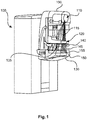
- Figs. 1 and 2 show a scanning mammography X-ray imaging device 100 to which principles of embodiments of the present invention may be applied.
- the scanning mammography X-ray imaging device 100 is a multi-slit X-ray scanner which is adapted for acquiring two-dimensional projection images for digital mammography.
- a patient is irradiated by a bundle of thin X-ray beams 145 each of which is detected by a corresponding line 155 of detector elements of an X-ray line detector 150.
- Each beam may have a rectangular cross-section being typically a few centimeters, for example 4 cm, wide and several tenth of micrometers, for example 50 ⁇ m, across.
- the narrow X-ray beams 145 are created by passing an initial X-ray beam 115 emitted by an X-ray source 110 through a collimator 120.
- This collimator 120 is a metal plate with several narrow linear apertures, also referred to as slits.
- slits For each slit there is one corresponding line 155 of detector elements in the X-ray line detector 150.
- Such line 155 may be a one-dimensional silicon array of pixel detectors for detector elements.
- the lines 155 are arranged to scan virtually a same area of the patient, yielding redundant information and enabling noise reduction.
- the line detectors 155 are mounted in an assembly of an X-ray line detector 150.
- a female breast to be irradiated may be compressed using a compression plate 140.
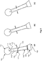
- the X-ray source 110 and the X-ray line detector 150 are coupled to a same arm 101 and are arranged at opposite sides with respect to an observation volume 135 between the compression plate 140 and the X-ray line detector 150.
- the arm 101 may be pivoted about a hinge situated close to the X-ray source 110 wherein a pivoting motion may be driven by a moving mechanism 130.
- the pivoting motion or scanning motion is indicated by the arrow 160 in Fig. 2 and is such that a center axis of the X-ray beam 115 is rotated around an axis orthogonal to this center axis.
- a scanning X-ray imaging device as or similar to the device 100 shown in Figs. 1 and 2 , features of embodiments of the present invention may be beneficial to reduce a patient X-ray dose and a local exposure time when the device is operated with a limited scan length, i.e. a limited motion distance along the direction 160.
- a modified scanning X-ray imaging device according to an embodiment of the present invention could be for example used in order to perform a stereo scan that may be needed for producing images related to biopsy targeting.
- a certain number of detector lines 155 may be required for building up a final image.
- Making use of many lines 155 of detector elements may have various advantages such as reducing a workload for the X-ray source 110, enabling to reduce random noise and producing a larger tomography angle (when the same device is also used for tomosynthesis) with other parameters kept constant as the more lines the wider is the detector arrangement.
- a wider detector arrangement with many detector lines 155 may also have some disadvantages.
- image areas where not the full detector arrangement has passed with all detector lines, i.e. in a start area and a stop area there will be a dose profile. This may result in lower image quality with more noise in these areas.
- the scan length is short in relation to a detector arrangement width, this effect may be significant.
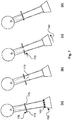
- Figs. 3 to 9 refer to a conventional device whereas Figs. 6 to 9 refer to a device according to an embodiment of the present invention.
- FIG. 3 shows main features of a conventional scanning X-ray imaging device with a field limiter arrangement having fixed or stationary shield plates and the sequence of Fig. 3(a) to Fig. 3(c) illustrates an operating principle of such device.
- Figs. 4 and 5 illustrate how lines of X-ray detector elements in an X-ray line detector of such conventional device are irradiated during normal operation, i.e. during an image acquisition procedure of short scan length, and a corresponding dose level distribution, respectively.
- Fig. 6 shows an embodiment of a scanning X-ray imaging device according to the present invention having a field limiter arrangement with two variable, i.e. displaceable, shield plates. The sequence of Figs.
- FIG. 7(a)-(d) illustrates an operating principle of such device.
- Figs. 8 and 9 illustrate irradiation characteristics of the lines of X-ray detector elements of an X-ray line detector of such inventive device and a corresponding dose level distribution, respectively.
- the conventional scanning X-ray imaging device 100 shown in Fig. 3 and the scanning X-ray imaging device according to an embodiment of the present invention shown in Figs. 6 and 7 both comprise an X-ray source 110, an X-ray line detector 150, a field limiter arrangement 170 and an observation volume 135.
- the X-ray source 110 and the X-ray line detector 150 are mechanically coupled to each other via an arm 101.
- Figs. 3 , 6 and 7 are only very schematical and only show these basic features of a scanning X-ray imaging device, one skilled in the art understands that such device 100 may comprise additional structural features and elements and the features and elements shown in the figures may be embodied in a more complex manner than shown in the figures.
- the X-ray source 110 may be a conventional X-ray tube having a tube focus 111 from which an X-ray beam 115 is emitted towards the X-ray line detector 150.
- the X-ray line detector 150 generally comprises multiple lines 155 of X-ray detector elements. Each line 155 comprises a plurality of X-ray detector elements arranged linearly in a line direction substantially orthogonal to the X-ray beam 115. In Figs. 3 and 6 , this line direction is orthogonal to the paper plane. Accordingly, when the X-ray line detector 150 is displaced along the scanning direction 160 by the moving mechanism 130, several of the lines 155 of X-ray detector elements are scanned through a region of interest of an object situated within the observation volume 135.
- the X-ray line detector 150 comprises four modules, each module comprising seven lines of X-ray detector elements such that the X-ray line detector 150 comprises a total of 28 lines 155 of X-ray detector elements (wherein in the figures, only four of these lines 155 are depicted).
- a width of the X-ray line detector 150 is about 67 mm.
- a scanning velocity along the scanning direction 160 will be tuned in such a way that a nominal image quality is reached after seven lines 155 of X-ray detector elements of scanning.
- the nominal image quality typically refers to an image quality used in X-ray screening.
- An image width required is 93 mm in a plane of the X-ray line detector 150. Such image width may be relevant for biopsy applications.
- a scan movement will be 23 lines which corresponds to 55 mm with an X-ray line detector 150 as shown.
- a scanning operation in this example may be a stereo scan. This means that two small two-dimensional scans are performed around a nominal angle of the scan arm 101 at +/-15°. Therein, a rotation axle is around the focus tube 111.
- An angle span of the scan arm 101 may be for example from 12.4° - 17.6°.
- a reason for the small scan length presented above may be that a detector movement is generally limited by a total height of a patient support table.
- a scan velocity needs to be low so that contributions from few detector lines will be sufficient to reach the desired image quality, and the removed area with insufficient contributions is minimized.
- At least one detector module i.e. at least seven lines of X-ray detector elements, has to pass the object of interest.
- the scan speed may be tuned down to give a nominal dose level (compared to a typical screening mammography dose) already after seven lines of X-ray detector elements.
- An object area passed by less than seven lines should preferably be shielded from X-ray dose since a resulting X-ray image will not reach a desired or required image quality.
- Making use of the method of slowing down the scan velocity to create an image already after seven lines of X-ray detector elements may be necessary to end up with a feasible relation between an image size and a total height of the patient support table.
- the field limiter arrangement 170 generally comprises fixed shield plates 171, 172 with an opening 173 of fixed cross-section between these shield plates.
- An area more central in the image will be generally scanned by more than the needed seven lines 155 of X-ray detector elements. This will generally build up both a dose level given to the tissue of a patient as well as a local exposure time of that tissue.
- the X-ray line detector 150 comprises 28 lines of X-ray detector elements. If the scan length would be longer than the detector width, the central part of the object would receive approximately 4 times higher dose and exposure time than required for the nominal dose.
- the geometry of the example device 100 may however limit the dose somewhat since the scan length is shorter than the detector width.
- the required image width is about 93 mm at the detector plane and this requires a scan length of 55 mm.
- Figs. 3(a)-(c) illustrate an operating principle of the conventional scanning X-ray imaging device with fixed shielding plates 171, 172.
- Fig. 3(a) shows a start position in which seven lines are shielded by the left shield plate 171.
- Fig. 3(b) shows a middle position in which no lines 155 of X-ray detector elements are shielded by any of the shield plates 171, 172.
- Fig. 3(c) shows an end position in which seven lines 155 of X-ray detector elements are shielded by the right shield plate 172.
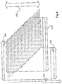
- Fig. 4 illustrates the operation principle of the scanning X-ray imaging device 100 of Fig. 3 with an ordinary stationary field limiter arrangement 170 cutting off seven lines 155 of X-ray detector elements at a beginning and at an end of a scanning motion.
- the figure illustrates the X-ray line detector 150 with 28 lines 155 of X-ray detector elements moving from left to right, indicated by the arrow 200.
- the grey area represents the resulting image comprising in total 93 mm or 39 lines 155 of detector elements as indicated by the arrow 210.
- a sum of each grey column indicates a dose level and exposure time, starting and ending with a nominal dose created by seven lines 150 of X-ray detector elements as indicated by the arrow 220.
- the scan length is indicated by the arrow 230 and comprises 23 lines 155 of detector elements corresponding to 55 mm at the detector plane.
- the non-grey area in Fig. 4 indicates the detector lines 155 shielded by the standard stationary field limiter arrangement 170 since in such region the number of lines 155 for acquiring image information would be less than seven and thus the image quality would not be up to nominal level.
- the arrow 240 indicates the steps during a scanning motion.
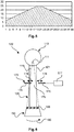
- Fig. 5 illustrates a dose level distribution when acquiring a scanning X-ray image as described above with reference to Figs. 3 and 4 .
- a number of lines 155 of X-ray detector elements irradiated during image acquisition corresponds to a dose level and is represented in Fig. 5 over the image width including 39 lines 155.
- Fig. 6 schematically illustrates a scanning X-ray imaging device 100 according to an embodiment of the present invention. Most of the components are same or similar to the components described above with respect to the conventional device 100 of Fig. 3 and therefore are indicated with the same reference signs.
- the device 100 of Fig. 6 differs from conventional devices in that the field limiter arrangement 170 does not comprise stationary shield plates 171, 172 but comprises variable shield plates 174, 175 which may be displaced independently from each other.
- the variable shield plates 174, 175 may be displaces, inter alia, with respect to each other.
- a cross sectional area of an opening 176 between the variable shield plates 174, 175 may be varied by displacing the variable shield plates 174, 175.
- the variable shield plates 174, 175 may be specifically displaced such that a location of a centre of the opening 176 is displaced relative to the X-ray line detector 150.
- a displacing mechanism 177 is provided for displacing each of the variable shield plates 174, 175.
- the displacement mechanism 177 may displace the variable shield plates 174, 175 in a plane parallel to a detection surface of the X-ray line detector 150 and in a direction 178 orthogonal to a line direction in which the lines 155 of X-ray detector elements are oriented.
- Figs. 7(a) to 7(d) show a sequence of operation steps performed during a scanning motion of an image acquisition procedure using the inventive scanning X-ray imaging device of Fig. 6 .
- the field limiter arrangement 170 is controlled such that all lines 155 of detector elements of the X-ray line detector 150 are shielded, i.e. the field limiter arrangement 170 is completely closed.
- the left shield plate 174 shields seven lines 155 of detector elements and is steady in room.
- the right plate 175 is arranged directly adjacent to the left plate 174.
- a detector scan starts at a relative speed 1.
- the right shield plate 175 starts displacing with a relative speed about 16/7, i.e. about 2 times faster than the speed of the detector.
- the left shield plate 174 does not shield any lines 155 of detector elements anymore.
- the opening 176 or gap between the shield plates 174, 175 has opened to 16 lines 155 of detector elements with a linear motion, i.e. at constant speed.
- the left shield plate 174 starts moving with the same speed as the right shield plate 175, i.e. at a relative speed of 16/7.
- a third step as shown in Fig. 7(c) in which the detector 150 has moved by 18 lines 155 of detector elements, the opening 176 is still opened to 16 lines 155 of detector elements.
- the left shield plate 174 shields 13 lines 155 of detector elements
- the right shield plate 175 shields no lines 155 of detector elements.
- the right shield plate 175 is stopped moving and is kept steady in room.
- the left shield plate 174 continues to move with the same speed, i.e. a relative speed of 16/7.
- a fourth step as shown in Fig. 7(d) in which the detector 150 has moved by 23 lines 155 of detector elements, the opening 176 is again closed completely and all lines 155 of detector elements are shielded.
- the detector scan i.e. the image acquisition procedure, may stop at this stage.
- the width of the produced image is 39 lines, i.e. about 93mm in the detector plane.
- the moving mechanism 130 is controlled to perform a scanning motion such that at least portions of the X-ray beam are scanned in a direction 160 through a region of interest within the observation volume and, synchronously herewith, the displacing mechanism 177 is controlled such that the opening 176 between the variable shield plates 174, 175 is first successively opened to a larger cross section, then kept at a constant cross section for a while and then finally closed again to a smaller cross section successively.
- the opening 176 there between is continuously moved relative to the X-ray line detector 150, i.e. in the direction 179 shown in Fig. 7(c) .
- the shield plates 174, 175 are only slightly opened and the opening 176 is closer to a left edge of the X-ray detector 150. Then, in the middle of the image acquisition procedure (stages between the stages shown in Fig. 7(b) and fig. 7(c) ), the shield plates 174, 175 are opened to a maximum and the opening 176 is situated somewhere between the left and right edges of the X-ray detector 150. At the end of the image acquisition procedure (stages in and shortly before the stage shown in Fig. 7(d) ), the shield plates 174, 175 are again only slightly opened and the opening 176 is closer to a right edge of the X-ray detector 150.
- Fig. 8 illustrates the operation principle of the inventive scanning X-ray imaging device 100 of Figs. 6 and 7 with a field limiter arrangement 170 including variable shield plates 174, 175. Similar to Fig. 4 , Figure 8 illustrates the X-ray line detector 150 with 28 lines 155 of X-ray detector elements moving from left to right, indicated by the arrow 200. The grey area represents the resulting image comprising in total 93 mm or 39 lines 155 of 28 lines 155 of X-ray detector elements moving from left to right, indicated by the arrow 200. The grey area represents the resulting image comprising in total 93 mm or 39 lines 155 of detector elements as indicated by the arrow 210. A sum of each grey column indicates a dose level.
- the device according to embodiments of the present invention allows to keep constant the dose level and exposure time for all sub-regions of the scanned region of interest as indicated by the arrow 220. This means that also the image quality will be uniform.
- the dose level and exposure time constantly corresponding to 7 lines 155 of detector elements, as also shown in Fig. 9 .
- the scan length is indicated by the arrow 230 and comprises 23 lines 155 of detector elements corresponding to 55 mm at the detector plane.
- the non-grey area in Fig. 8 indicates the detector lines 155 shielded by the field limiter arrangement 170 since in such region the number of lines 155 for acquiring image information would be less than seven and thus the image quality would not be up to nominal level.
- the arrow 240 indicates the steps during a scanning motion.
- the arrow 250 indicates the maximum opening 176, i.e. the maximum field limiter width, of 16 lines 155 of detector elements, corresponding to 38mm.
- Fig. 9 illustrates a dose level distribution when acquiring a scanning X-ray image as described above with reference to Figs. 7 and 8 .
- a number of lines 155 of X-ray detector elements irradiated during image acquisition corresponds to a dose level and is represented in Fig. 5 over the image width including 39 lines 155. This number of lines 155 of X-ray detector elements is constant throughout the entire image width. Accordingly, in the inventive scanning X-ray imaging device with a variable field limiter arrangement 170, there occurs no excessive dose level or X-ray exposure at the middle of the image and an overall dose level is permanently kept at a required minimum for sufficient image quality.
- the device may be specifically adapted for mammography applications.
- the device comprises an X-ray source 110, an X-ray line detector 150, a field limiter arrangement 170 and an observation volume 135.
- the field limiter arrangement 170 comprises at least two variable shield plates 174, 175 enclosing an opening 176 and a displacing mechanism 177.
- the shield plates may be displaced with respect to a centre axis of an X-ray beam 115 by means of the displacing mechanism such as to vary at least one of a cross-section and a location of the opening 176 between the shield plates 174, 175 through which at least a part of the X-ray beam 115 is transmitted.
- the shield plates may be displaced independently from each other by means of the displacing mechanism 177.
- Such device 100 may be operated to perform a scanning motion such as to scan at least portions of the X-ray beam through a region of interest within the observation volume 135 and, at the same time, control the displacing mechanism 177 such that the opening 176 between the shield plates 174, 175 is first successively opened to a larger cross-section and then successively closed again to a smaller cross-section during the scanning motion.
- a scanning motion such as to scan at least portions of the X-ray beam through a region of interest within the observation volume 135 and, at the same time, control the displacing mechanism 177 such that the opening 176 between the shield plates 174, 175 is first successively opened to a larger cross-section and then successively closed again to a smaller cross-section during the scanning motion.
Landscapes
- Health & Medical Sciences (AREA)
- Life Sciences & Earth Sciences (AREA)
- Engineering & Computer Science (AREA)
- Medical Informatics (AREA)
- Physics & Mathematics (AREA)
- High Energy & Nuclear Physics (AREA)
- Heart & Thoracic Surgery (AREA)
- Animal Behavior & Ethology (AREA)
- Optics & Photonics (AREA)
- Pathology (AREA)
- Radiology & Medical Imaging (AREA)
- Biomedical Technology (AREA)
- Biophysics (AREA)
- Molecular Biology (AREA)
- Surgery (AREA)
- Nuclear Medicine, Radiotherapy & Molecular Imaging (AREA)
- General Health & Medical Sciences (AREA)
- Public Health (AREA)
- Veterinary Medicine (AREA)
- Dentistry (AREA)
- Oral & Maxillofacial Surgery (AREA)
- Spectroscopy & Molecular Physics (AREA)
- General Engineering & Computer Science (AREA)
- Apparatus For Radiation Diagnosis (AREA)
Priority Applications (1)
| Application Number | Priority Date | Filing Date | Title |
|---|---|---|---|
| EP14808955.0A EP3079593B1 (en) | 2013-12-09 | 2014-12-04 | Scanning x-ray imaging device with variable shield plates and method for operating same |
Applications Claiming Priority (3)
| Application Number | Priority Date | Filing Date | Title |
|---|---|---|---|
| EP13196323 | 2013-12-09 | ||
| EP14808955.0A EP3079593B1 (en) | 2013-12-09 | 2014-12-04 | Scanning x-ray imaging device with variable shield plates and method for operating same |
| PCT/EP2014/076474 WO2015086412A1 (en) | 2013-12-09 | 2014-12-04 | Scanning x-ray imaging device with variable shield plates and method for operating same |
Publications (2)
| Publication Number | Publication Date |
|---|---|
| EP3079593A1 EP3079593A1 (en) | 2016-10-19 |
| EP3079593B1 true EP3079593B1 (en) | 2018-05-09 |
Family
ID=49753034
Family Applications (1)
| Application Number | Title | Priority Date | Filing Date |
|---|---|---|---|
| EP14808955.0A Not-in-force EP3079593B1 (en) | 2013-12-09 | 2014-12-04 | Scanning x-ray imaging device with variable shield plates and method for operating same |
Country Status (5)
| Country | Link |
|---|---|
| US (1) | US10376225B2 (enExample) |
| EP (1) | EP3079593B1 (enExample) |
| JP (1) | JP6408003B2 (enExample) |
| CN (1) | CN105813571B (enExample) |
| WO (1) | WO2015086412A1 (enExample) |
Families Citing this family (6)
| Publication number | Priority date | Publication date | Assignee | Title |
|---|---|---|---|---|
| JP6852988B2 (ja) * | 2016-06-16 | 2021-03-31 | キヤノンメディカルシステムズ株式会社 | マンモグラフィ装置 |
| CN109357764B (zh) * | 2018-08-09 | 2021-06-15 | 北京理工大学 | 一种双探测器动态局部偏振成像系统 |
| CN113116364B (zh) * | 2019-12-31 | 2023-07-14 | 上海联影医疗科技股份有限公司 | 一种乳腺x射线成像装置 |
| WO2021129816A1 (en) | 2019-12-28 | 2021-07-01 | Shanghai United Imaging Healthcare Co., Ltd. | Imaging systems and methods |
| DE102020204172A1 (de) * | 2020-03-31 | 2021-09-30 | Siemens Healthcare Gmbh | Verfahren zur Aufnahme einer erweiterten Röntgenaufnahme |
| ES2986702T3 (es) * | 2020-09-07 | 2024-11-12 | Inst De Fisica Daltes Energies Ifae | Dispositivos y procedimientos para imágenes médicas |
Family Cites Families (13)
| Publication number | Priority date | Publication date | Assignee | Title |
|---|---|---|---|---|
| US4143273A (en) * | 1977-04-11 | 1979-03-06 | Ohio-Nuclear, Inc. | Variable collimator |
| US4953192A (en) * | 1986-04-14 | 1990-08-28 | The University Of Rochester | Scanning equalization radiography |
| JP3999179B2 (ja) | 2003-09-09 | 2007-10-31 | ジーイー・メディカル・システムズ・グローバル・テクノロジー・カンパニー・エルエルシー | 放射線断層撮影装置 |
| US7194061B2 (en) * | 2004-09-14 | 2007-03-20 | Kabushiki Kaisha Toshiba | X-ray computer tomography apparatus |
| US7302031B2 (en) | 2005-10-27 | 2007-11-27 | Sectra Mamea Ab | Method and arrangement relating to X-ray imaging |
| DE102007028902B4 (de) * | 2007-06-22 | 2009-04-16 | Siemens Ag | Strahlerblende, Verfahren zu deren Steuerung und Röntgen-CT-Vorrichtung mit derartiger Strahlerblende |
| US8213568B2 (en) | 2007-12-21 | 2012-07-03 | Koninklijke Philips Electronics N.V. | Dynamic collimation in cone beam computed tomography to reduce patient exposure |
| JP5384612B2 (ja) * | 2008-03-31 | 2014-01-08 | コーニンクレッカ フィリップス エヌ ヴェ | コーンビームボリュームctマンモグラフィー撮像に使用するための、管が連続して移動している間、焦点を動かさない回転式のステップ・アンド・シュート画像取得に基づく、高速トモシンセシススキャナ装置及びctベースの方法 |
| JP2010082428A (ja) * | 2008-09-04 | 2010-04-15 | Toshiba Corp | X線コンピュータ断層撮影装置 |
| DE102008050571A1 (de) * | 2008-10-06 | 2010-04-15 | Siemens Aktiengesellschaft | Tomosynthesegerät und Verfahren zum Betrieb eines Tomosynthesegerätes |
| DE102009016770A1 (de) | 2009-04-07 | 2010-10-21 | Siemens Aktiengesellschaft | Verfahren und Vorrichtung zum Erzeugen von Projektionen vom Inneren eines Untersuchungsobjekts |
| JP2011019633A (ja) * | 2009-07-14 | 2011-02-03 | Toshiba Corp | X線診断装置及び被曝線量低減用制御プログラム |
| US8649479B2 (en) * | 2010-11-22 | 2014-02-11 | General Electric Company | System and method for breast imaging using X-ray computed tomography |
-
2014
- 2014-12-04 JP JP2016536950A patent/JP6408003B2/ja not_active Expired - Fee Related
- 2014-12-04 US US15/101,957 patent/US10376225B2/en not_active Expired - Fee Related
- 2014-12-04 CN CN201480067140.9A patent/CN105813571B/zh not_active Expired - Fee Related
- 2014-12-04 WO PCT/EP2014/076474 patent/WO2015086412A1/en not_active Ceased
- 2014-12-04 EP EP14808955.0A patent/EP3079593B1/en not_active Not-in-force
Non-Patent Citations (1)
| Title |
|---|
| None * |
Also Published As
| Publication number | Publication date |
|---|---|
| JP6408003B2 (ja) | 2018-10-17 |
| US20160310087A1 (en) | 2016-10-27 |
| CN105813571A (zh) | 2016-07-27 |
| CN105813571B (zh) | 2020-06-30 |
| EP3079593A1 (en) | 2016-10-19 |
| JP2016539709A (ja) | 2016-12-22 |
| WO2015086412A1 (en) | 2015-06-18 |
| US10376225B2 (en) | 2019-08-13 |
Similar Documents
| Publication | Publication Date | Title |
|---|---|---|
| EP3079593B1 (en) | Scanning x-ray imaging device with variable shield plates and method for operating same | |
| JP6334898B2 (ja) | コリメータ、及び該コリメータを備えた計算機式断層写真法(ct)システム | |
| CN106030264B (zh) | X射线减少系统 | |
| EP2727119B1 (en) | X-ray beam transmission profile shaper | |
| JP5855156B2 (ja) | コリメータ装置、コリメータ装置の制御方法および制御装置ならびにx線コンピュータ断層撮影装置 | |
| CN106340340B (zh) | X射线滤波 | |
| US9901315B2 (en) | X-ray scatter reducing device for use with 2D mammography and tomosynthesis | |
| KR20110094182A (ko) | X선 촬영 장치 | |
| KR20180065351A (ko) | 방사선 촬영 장치 및 이를 이용한 방사선 촬영 방법 | |
| KR101174351B1 (ko) | 디지털 x―선 이미징을 위한 단층영상합성 시스템 및 그 제어 방법 | |
| JP2006175230A (ja) | X線コンピュータ断層撮影装置 | |
| EP3850346B1 (en) | Dynamic radiation collimation for non-destructive analysis of test objects | |
| US11234662B2 (en) | Method and device for changing the spatial intensity distribution of an x-ray beam | |
| KR20180106438A (ko) | 방사선 촬영 장치 및 이를 이용한 방사선 촬영 방법 | |
| JP2006297111A (ja) | X線装置用の絞り装置およびx線装置用の絞り装置の作動方法。 | |
| US11109827B2 (en) | X-ray imaging apparatus | |
| US12369869B2 (en) | Systems and methods for an integrated filter assembly with two carriages | |
| US11249034B2 (en) | X-ray Talbot capturing apparatus | |
| JP2013140121A (ja) | 放射線検出装置および放射線断層撮影装置 | |
| JP2001112747A (ja) | X線ct装置 | |
| KR102596189B1 (ko) | Ct 장치 | |
| CN114302678B (zh) | X射线成像设备和方法 | |
| CN105769231A (zh) | 一种限束器在z轴上的射线跟踪方法 | |
| JP2008051548A (ja) | コンピュータ断層撮影装置 |
Legal Events
| Date | Code | Title | Description |
|---|---|---|---|
| PUAI | Public reference made under article 153(3) epc to a published international application that has entered the european phase |
Free format text: ORIGINAL CODE: 0009012 |
|
| 17P | Request for examination filed |
Effective date: 20160711 |
|
| AK | Designated contracting states |
Kind code of ref document: A1 Designated state(s): AL AT BE BG CH CY CZ DE DK EE ES FI FR GB GR HR HU IE IS IT LI LT LU LV MC MK MT NL NO PL PT RO RS SE SI SK SM TR |
|
| AX | Request for extension of the european patent |
Extension state: BA ME |
|
| DAX | Request for extension of the european patent (deleted) | ||
| GRAP | Despatch of communication of intention to grant a patent |
Free format text: ORIGINAL CODE: EPIDOSNIGR1 |
|
| INTG | Intention to grant announced |
Effective date: 20171130 |
|
| GRAS | Grant fee paid |
Free format text: ORIGINAL CODE: EPIDOSNIGR3 |
|
| GRAA | (expected) grant |
Free format text: ORIGINAL CODE: 0009210 |
|
| AK | Designated contracting states |
Kind code of ref document: B1 Designated state(s): AL AT BE BG CH CY CZ DE DK EE ES FI FR GB GR HR HU IE IS IT LI LT LU LV MC MK MT NL NO PL PT RO RS SE SI SK SM TR |
|
| REG | Reference to a national code |
Ref country code: GB Ref legal event code: FG4D |
|
| REG | Reference to a national code |
Ref country code: CH Ref legal event code: EP Ref country code: AT Ref legal event code: REF Ref document number: 996779 Country of ref document: AT Kind code of ref document: T Effective date: 20180515 |
|
| REG | Reference to a national code |
Ref country code: IE Ref legal event code: FG4D |
|
| REG | Reference to a national code |
Ref country code: DE Ref legal event code: R096 Ref document number: 602014025360 Country of ref document: DE |
|
| REG | Reference to a national code |
Ref country code: DE Ref legal event code: R084 Ref document number: 602014025360 Country of ref document: DE |
|
| REG | Reference to a national code |
Ref country code: GB Ref legal event code: 746 Effective date: 20180803 |
|
| REG | Reference to a national code |
Ref country code: NL Ref legal event code: MP Effective date: 20180509 |
|
| REG | Reference to a national code |
Ref country code: LT Ref legal event code: MG4D |
|
| PG25 | Lapsed in a contracting state [announced via postgrant information from national office to epo] |
Ref country code: ES Free format text: LAPSE BECAUSE OF FAILURE TO SUBMIT A TRANSLATION OF THE DESCRIPTION OR TO PAY THE FEE WITHIN THE PRESCRIBED TIME-LIMIT Effective date: 20180509 Ref country code: SE Free format text: LAPSE BECAUSE OF FAILURE TO SUBMIT A TRANSLATION OF THE DESCRIPTION OR TO PAY THE FEE WITHIN THE PRESCRIBED TIME-LIMIT Effective date: 20180509 Ref country code: NO Free format text: LAPSE BECAUSE OF FAILURE TO SUBMIT A TRANSLATION OF THE DESCRIPTION OR TO PAY THE FEE WITHIN THE PRESCRIBED TIME-LIMIT Effective date: 20180809 Ref country code: BG Free format text: LAPSE BECAUSE OF FAILURE TO SUBMIT A TRANSLATION OF THE DESCRIPTION OR TO PAY THE FEE WITHIN THE PRESCRIBED TIME-LIMIT Effective date: 20180809 Ref country code: LT Free format text: LAPSE BECAUSE OF FAILURE TO SUBMIT A TRANSLATION OF THE DESCRIPTION OR TO PAY THE FEE WITHIN THE PRESCRIBED TIME-LIMIT Effective date: 20180509 Ref country code: FI Free format text: LAPSE BECAUSE OF FAILURE TO SUBMIT A TRANSLATION OF THE DESCRIPTION OR TO PAY THE FEE WITHIN THE PRESCRIBED TIME-LIMIT Effective date: 20180509 |
|
| PG25 | Lapsed in a contracting state [announced via postgrant information from national office to epo] |
Ref country code: GR Free format text: LAPSE BECAUSE OF FAILURE TO SUBMIT A TRANSLATION OF THE DESCRIPTION OR TO PAY THE FEE WITHIN THE PRESCRIBED TIME-LIMIT Effective date: 20180810 Ref country code: NL Free format text: LAPSE BECAUSE OF FAILURE TO SUBMIT A TRANSLATION OF THE DESCRIPTION OR TO PAY THE FEE WITHIN THE PRESCRIBED TIME-LIMIT Effective date: 20180509 Ref country code: RS Free format text: LAPSE BECAUSE OF FAILURE TO SUBMIT A TRANSLATION OF THE DESCRIPTION OR TO PAY THE FEE WITHIN THE PRESCRIBED TIME-LIMIT Effective date: 20180509 Ref country code: HR Free format text: LAPSE BECAUSE OF FAILURE TO SUBMIT A TRANSLATION OF THE DESCRIPTION OR TO PAY THE FEE WITHIN THE PRESCRIBED TIME-LIMIT Effective date: 20180509 Ref country code: LV Free format text: LAPSE BECAUSE OF FAILURE TO SUBMIT A TRANSLATION OF THE DESCRIPTION OR TO PAY THE FEE WITHIN THE PRESCRIBED TIME-LIMIT Effective date: 20180509 |
|
| REG | Reference to a national code |
Ref country code: AT Ref legal event code: MK05 Ref document number: 996779 Country of ref document: AT Kind code of ref document: T Effective date: 20180509 |
|
| PG25 | Lapsed in a contracting state [announced via postgrant information from national office to epo] |
Ref country code: CZ Free format text: LAPSE BECAUSE OF FAILURE TO SUBMIT A TRANSLATION OF THE DESCRIPTION OR TO PAY THE FEE WITHIN THE PRESCRIBED TIME-LIMIT Effective date: 20180509 Ref country code: RO Free format text: LAPSE BECAUSE OF FAILURE TO SUBMIT A TRANSLATION OF THE DESCRIPTION OR TO PAY THE FEE WITHIN THE PRESCRIBED TIME-LIMIT Effective date: 20180509 Ref country code: SK Free format text: LAPSE BECAUSE OF FAILURE TO SUBMIT A TRANSLATION OF THE DESCRIPTION OR TO PAY THE FEE WITHIN THE PRESCRIBED TIME-LIMIT Effective date: 20180509 Ref country code: DK Free format text: LAPSE BECAUSE OF FAILURE TO SUBMIT A TRANSLATION OF THE DESCRIPTION OR TO PAY THE FEE WITHIN THE PRESCRIBED TIME-LIMIT Effective date: 20180509 Ref country code: EE Free format text: LAPSE BECAUSE OF FAILURE TO SUBMIT A TRANSLATION OF THE DESCRIPTION OR TO PAY THE FEE WITHIN THE PRESCRIBED TIME-LIMIT Effective date: 20180509 Ref country code: AT Free format text: LAPSE BECAUSE OF FAILURE TO SUBMIT A TRANSLATION OF THE DESCRIPTION OR TO PAY THE FEE WITHIN THE PRESCRIBED TIME-LIMIT Effective date: 20180509 Ref country code: PL Free format text: LAPSE BECAUSE OF FAILURE TO SUBMIT A TRANSLATION OF THE DESCRIPTION OR TO PAY THE FEE WITHIN THE PRESCRIBED TIME-LIMIT Effective date: 20180509 |
|
| REG | Reference to a national code |
Ref country code: DE Ref legal event code: R097 Ref document number: 602014025360 Country of ref document: DE |
|
| PG25 | Lapsed in a contracting state [announced via postgrant information from national office to epo] |
Ref country code: IT Free format text: LAPSE BECAUSE OF FAILURE TO SUBMIT A TRANSLATION OF THE DESCRIPTION OR TO PAY THE FEE WITHIN THE PRESCRIBED TIME-LIMIT Effective date: 20180509 Ref country code: SM Free format text: LAPSE BECAUSE OF FAILURE TO SUBMIT A TRANSLATION OF THE DESCRIPTION OR TO PAY THE FEE WITHIN THE PRESCRIBED TIME-LIMIT Effective date: 20180509 |
|
| PLBE | No opposition filed within time limit |
Free format text: ORIGINAL CODE: 0009261 |
|
| STAA | Information on the status of an ep patent application or granted ep patent |
Free format text: STATUS: NO OPPOSITION FILED WITHIN TIME LIMIT |
|
| 26N | No opposition filed |
Effective date: 20190212 |
|
| PG25 | Lapsed in a contracting state [announced via postgrant information from national office to epo] |
Ref country code: SI Free format text: LAPSE BECAUSE OF FAILURE TO SUBMIT A TRANSLATION OF THE DESCRIPTION OR TO PAY THE FEE WITHIN THE PRESCRIBED TIME-LIMIT Effective date: 20180509 |
|
| REG | Reference to a national code |
Ref country code: CH Ref legal event code: PL |
|
| PG25 | Lapsed in a contracting state [announced via postgrant information from national office to epo] |
Ref country code: MC Free format text: LAPSE BECAUSE OF FAILURE TO SUBMIT A TRANSLATION OF THE DESCRIPTION OR TO PAY THE FEE WITHIN THE PRESCRIBED TIME-LIMIT Effective date: 20180509 Ref country code: LU Free format text: LAPSE BECAUSE OF NON-PAYMENT OF DUE FEES Effective date: 20181204 |
|
| REG | Reference to a national code |
Ref country code: IE Ref legal event code: MM4A |
|
| REG | Reference to a national code |
Ref country code: BE Ref legal event code: MM Effective date: 20181231 |
|
| PG25 | Lapsed in a contracting state [announced via postgrant information from national office to epo] |
Ref country code: IE Free format text: LAPSE BECAUSE OF NON-PAYMENT OF DUE FEES Effective date: 20181204 |
|
| PG25 | Lapsed in a contracting state [announced via postgrant information from national office to epo] |
Ref country code: AL Free format text: LAPSE BECAUSE OF FAILURE TO SUBMIT A TRANSLATION OF THE DESCRIPTION OR TO PAY THE FEE WITHIN THE PRESCRIBED TIME-LIMIT Effective date: 20180509 Ref country code: BE Free format text: LAPSE BECAUSE OF NON-PAYMENT OF DUE FEES Effective date: 20181231 |
|
| PG25 | Lapsed in a contracting state [announced via postgrant information from national office to epo] |
Ref country code: CH Free format text: LAPSE BECAUSE OF NON-PAYMENT OF DUE FEES Effective date: 20181231 Ref country code: LI Free format text: LAPSE BECAUSE OF NON-PAYMENT OF DUE FEES Effective date: 20181231 |
|
| PG25 | Lapsed in a contracting state [announced via postgrant information from national office to epo] |
Ref country code: MT Free format text: LAPSE BECAUSE OF NON-PAYMENT OF DUE FEES Effective date: 20181204 |
|
| PG25 | Lapsed in a contracting state [announced via postgrant information from national office to epo] |
Ref country code: TR Free format text: LAPSE BECAUSE OF FAILURE TO SUBMIT A TRANSLATION OF THE DESCRIPTION OR TO PAY THE FEE WITHIN THE PRESCRIBED TIME-LIMIT Effective date: 20180509 |
|
| PG25 | Lapsed in a contracting state [announced via postgrant information from national office to epo] |
Ref country code: PT Free format text: LAPSE BECAUSE OF FAILURE TO SUBMIT A TRANSLATION OF THE DESCRIPTION OR TO PAY THE FEE WITHIN THE PRESCRIBED TIME-LIMIT Effective date: 20180509 |
|
| PG25 | Lapsed in a contracting state [announced via postgrant information from national office to epo] |
Ref country code: CY Free format text: LAPSE BECAUSE OF FAILURE TO SUBMIT A TRANSLATION OF THE DESCRIPTION OR TO PAY THE FEE WITHIN THE PRESCRIBED TIME-LIMIT Effective date: 20180509 Ref country code: HU Free format text: LAPSE BECAUSE OF FAILURE TO SUBMIT A TRANSLATION OF THE DESCRIPTION OR TO PAY THE FEE WITHIN THE PRESCRIBED TIME-LIMIT; INVALID AB INITIO Effective date: 20141204 Ref country code: MK Free format text: LAPSE BECAUSE OF NON-PAYMENT OF DUE FEES Effective date: 20180509 |
|
| PG25 | Lapsed in a contracting state [announced via postgrant information from national office to epo] |
Ref country code: IS Free format text: LAPSE BECAUSE OF FAILURE TO SUBMIT A TRANSLATION OF THE DESCRIPTION OR TO PAY THE FEE WITHIN THE PRESCRIBED TIME-LIMIT Effective date: 20180909 |
|
| PGFP | Annual fee paid to national office [announced via postgrant information from national office to epo] |
Ref country code: FR Payment date: 20201229 Year of fee payment: 7 Ref country code: GB Payment date: 20201228 Year of fee payment: 7 |
|
| PGFP | Annual fee paid to national office [announced via postgrant information from national office to epo] |
Ref country code: DE Payment date: 20201229 Year of fee payment: 7 |
|
| REG | Reference to a national code |
Ref country code: DE Ref legal event code: R119 Ref document number: 602014025360 Country of ref document: DE |
|
| GBPC | Gb: european patent ceased through non-payment of renewal fee |
Effective date: 20211204 |
|
| PG25 | Lapsed in a contracting state [announced via postgrant information from national office to epo] |
Ref country code: GB Free format text: LAPSE BECAUSE OF NON-PAYMENT OF DUE FEES Effective date: 20211204 Ref country code: DE Free format text: LAPSE BECAUSE OF NON-PAYMENT OF DUE FEES Effective date: 20220701 |
|
| PG25 | Lapsed in a contracting state [announced via postgrant information from national office to epo] |
Ref country code: FR Free format text: LAPSE BECAUSE OF NON-PAYMENT OF DUE FEES Effective date: 20211231 |