EP3071860B1 - Reibbelaganordnung für eine scheibenbremse - Google Patents
Reibbelaganordnung für eine scheibenbremse Download PDFInfo
- Publication number
- EP3071860B1 EP3071860B1 EP14799498.2A EP14799498A EP3071860B1 EP 3071860 B1 EP3071860 B1 EP 3071860B1 EP 14799498 A EP14799498 A EP 14799498A EP 3071860 B1 EP3071860 B1 EP 3071860B1
- Authority
- EP
- European Patent Office
- Prior art keywords
- back plate
- friction lining
- absorber system
- absorber
- friction
- Prior art date
- Legal status (The legal status is an assumption and is not a legal conclusion. Google has not performed a legal analysis and makes no representation as to the accuracy of the status listed.)
- Active
Links
- 239000006096 absorbing agent Substances 0.000 claims description 26
- 239000002783 friction material Substances 0.000 claims description 3
- 230000007704 transition Effects 0.000 claims description 2
- 238000010521 absorption reaction Methods 0.000 claims 1
- 230000000284 resting effect Effects 0.000 claims 1
- 230000000638 stimulation Effects 0.000 claims 1
- 230000010355 oscillation Effects 0.000 description 6
- 230000005284 excitation Effects 0.000 description 5
- 229910000831 Steel Inorganic materials 0.000 description 4
- 239000010959 steel Substances 0.000 description 4
- 239000000463 material Substances 0.000 description 3
- 238000013016 damping Methods 0.000 description 2
- 230000000694 effects Effects 0.000 description 2
- 238000004519 manufacturing process Methods 0.000 description 2
- 238000000034 method Methods 0.000 description 2
- 241000251131 Sphyrna Species 0.000 description 1
- 239000000853 adhesive Substances 0.000 description 1
- 238000004026 adhesive bonding Methods 0.000 description 1
- 230000001070 adhesive effect Effects 0.000 description 1
- 230000007423 decrease Effects 0.000 description 1
- 239000013013 elastic material Substances 0.000 description 1
- 229920001971 elastomer Polymers 0.000 description 1
- 239000000806 elastomer Substances 0.000 description 1
- 230000002349 favourable effect Effects 0.000 description 1
- 230000002452 interceptive effect Effects 0.000 description 1
- 238000012986 modification Methods 0.000 description 1
- 230000004048 modification Effects 0.000 description 1
- 239000004033 plastic Substances 0.000 description 1
- 238000003825 pressing Methods 0.000 description 1
- 238000004080 punching Methods 0.000 description 1
- 230000005855 radiation Effects 0.000 description 1
- 239000002699 waste material Substances 0.000 description 1
- 238000003466 welding Methods 0.000 description 1
Images


Classifications
-
- F—MECHANICAL ENGINEERING; LIGHTING; HEATING; WEAPONS; BLASTING
- F16—ENGINEERING ELEMENTS AND UNITS; GENERAL MEASURES FOR PRODUCING AND MAINTAINING EFFECTIVE FUNCTIONING OF MACHINES OR INSTALLATIONS; THERMAL INSULATION IN GENERAL
- F16D—COUPLINGS FOR TRANSMITTING ROTATION; CLUTCHES; BRAKES
- F16D65/00—Parts or details
- F16D65/0006—Noise or vibration control
- F16D65/0018—Dynamic vibration dampers, e.g. mass-spring systems
-
- F—MECHANICAL ENGINEERING; LIGHTING; HEATING; WEAPONS; BLASTING
- F16—ENGINEERING ELEMENTS AND UNITS; GENERAL MEASURES FOR PRODUCING AND MAINTAINING EFFECTIVE FUNCTIONING OF MACHINES OR INSTALLATIONS; THERMAL INSULATION IN GENERAL
- F16D—COUPLINGS FOR TRANSMITTING ROTATION; CLUTCHES; BRAKES
- F16D65/00—Parts or details
- F16D65/02—Braking members; Mounting thereof
- F16D65/04—Bands, shoes or pads; Pivots or supporting members therefor
- F16D65/092—Bands, shoes or pads; Pivots or supporting members therefor for axially-engaging brakes, e.g. disc brakes
Definitions
- the invention relates to a structure such as, in particular, a friction lining arrangement for a disc brake according to the preamble of patent claim 1.
- vibrations When braking, vibrations always occur to a certain extent.
- the vibrations are induced by intermittent frictional engagement between the friction material and the brake disc in a structure that is excited to vibrate. Depending on the prevailing conditions in individual cases, this can result in noises that are undesirable as a comfort-reducing phenomenon.
- noises In addition to the mechanical effects, such as uneven steering or vibrations on body components, the acoustic effects are particularly unpleasant.
- a vibration-related "detuning" of the system can be achieved by means of a rigidly placed additional mass.
- the additional mass vibrates together with the remaining structure in amplitude and frequency.
- One disadvantage is that the additional mass has to be dimensioned relatively large, that is, it causes weight disadvantages.
- the invention is therefore based on the object of enabling a more favorable and more efficient noise reduction, which does not unnecessarily increase the vehicle mass and also opens up advantageous production processes without impairing the performance characteristics and space requirements of a vehicle disc brake.
- a disc brake with at least one vibration-changing element To prevent braking noise.
- a measure which relates to a brake shoe with hammer-head-like extensions.
- at least one additional mass is rigidly placed on the hammer head-shaped continuation of the back plate.
- a round steel is used, which is fastened in a hole through a center of the hammer head, so that natural frequencies can be detuned or shifted against each other and ideally set so that they do not reinforce each other.
- the round steel is fastened, for example, by gluing, riveting, pressing, welding or screwing into the hole in the back plate.
- the invention therefore proposes a new type of damper system which is capable of vibrating separately from the structure.
- the proposed measure serves the goal of at least reducing or eliminating as far as possible vibrations in the circumferential direction and / or axial or other vibration level in a predetermined frequency range by withdrawing energy from the vibrating structure, because at the same time a damping system is separately excited.
- a new type of absorber system T is provided on the structure (friction lining) of a total mass, which comprises a spring with a predetermined spring stiffness and the predetermined partial mass suspended thereon, which are matched to one another, and can be elastically oscillated separately from the structure S by a slim leg the structure is arranged.
- This innovative damper system includes a spring function (eg in the SL leg integrated) and a mass. It serves to extinguish a certain interfering frequency / frequency band of the structure S.
- the damper system can be integrated on a component of the structure S, that is to say it can be provided in one piece, or alternatively the damper system T is attached to the structure as a separate assembly as in FIG Fig. 2-6 shown.
- the mode of operation of this absorber system is based on the basic principle that the mass of the absorber system executes a separate, forced oscillation with a separate amplitude due to the excitation on the basis of the defined frequency / frequency band to be combated, while the oscillation of the structure by the excitation of the absorber system removes oscillation energy becomes.
- vibration cancellation occurs to rest or to a vibration amplitude AS with subordinate intensity.
- a damping component or function can additionally be provided in an integrated manner without departing from the invention.
- the additional mass is placed on the slender leg (connecting section) between a central section of a back plate and a hammer-head-shaped projection or on the hammer-head-shaped projection and is arranged such that it can oscillate separately.
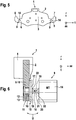
- Fig. 1 shows a symmetrical friction lining 1 comprising a back plate 2.
- the back plate 2 is largely flat and has a central section 3 with a largely centrally bonded friction material 4.
- Slim legs extend in a plane with the central section 3 and tangentially laterally projecting therefrom ( connecting portions) 5.6 which carry the thickened, hammer head-shaped projections 7.8.
- the hammer-head-shaped projections 7, 8 are designed such that their bodies point radially outward, and the slender legs 5, 6 carry the thickened bodies of the hammer heads 7, 8.
- These elements are thus arranged to a certain extent as legs arranged at right angles to one another, and in principle describe the shape of an L pointing radially outwards.
- the hammer head-shaped projections 7, 8 are connected to the central section 3 via the legs 5, 6.
- the exact design of the absorber system and its function is as follows: In order to effectively combat disturbing vibrations on the friction lining 1, the waveforms, in particular their amplitude and frequency, must be known. These quantities can be determined experimentally or mathematically.
- the absorber system is dimensioned and used to structure the vibrational energy of a given frequency / frequency band to withdraw.
- the damper system 9 consisting of damper mass MT and spring kf, is specifically adjusted to the frequency f, amplitude A and the vibration level / direction to be eliminated.
- the mass of the damper system 9 is attached to the structure in the region of a spring base point Ff.
- the damper system 9 Since the structure initially vibrates together with the damper system 9 (with the same frequency and amplitude), the damper system 9 is in turn excited to perform relative oscillations in order to perform separate counter-vibrations with the structure.
- the result of this excitation of the damper system 9 is that the structure is deprived of the vibrational energy that feeds the noise, so that the (mostly inaudible) non-disturbing relative vibration of the damper system 9 can be carried out.
- a disturbing sound radiation from the structure decreases or is completely extinguished.
- the absorber system 9 is an integral part of the back plate 2, which is integrally formed in the manufacturing process (stamping) of the back plate 2 without additional effort.
- Damper mass and damper spring are according to Fig. 1 defined by suitable execution / design of your geometry so that the desired natural frequency results in the desired, in particular tangentially directed, direction of oscillation.
- the connection between mass and structure is designed and defined as a largely flexible absorber spring.
- Their stiffness is determined by an elastic modulus of the back plate material as well as by the physical boundary conditions and the geometry of the determining sizes.
- the masses and their (spring) stiffness are defined Relationship to each other to ensure the required excitation / natural frequency.
- the damper system 9 can simply be represented as an integrated component of the back plate 2 in this stamping process.
- a damper D and or a damper component can be integrated parallel to the damper spring.
- the spatial axes t, ax, r in the figures define the tangential direction, axial direction and radial direction in each case with respect to a wheel axis of rotation which is normalized as the axial direction.
- the enlarged diameter section 12 with the fastening of the fastening pin 11 is located on the friction lining side of the back plate 2.
- the damper system 9 is thus placed on a side of the back plate 2 facing away from the friction lining. Due to the spatial proximity of the damper system 9, in relation to the central section 3, the energy transfer is optimized. As a result, the damper system 9 is particularly efficient, light and space-saving.
- the slender limb 5, 6 provides sufficient oscillation capability and inherent elasticity for vibrations from the damper system 9 (vibration U), preferably around the radial direction r (vertical axis), it is also conceivable to add an additional one between the damper system 9 and the back plate 2 to provide further elasticity such as a corrugated spring or an insert / intermediate layer made of an elastic material such as in particular adhesive, plastic or elastomer. In particular, this makes it possible for the damper system 9 to be / can also oscillate about axes other than or only the radial direction r.
- the Fig. 6 is based on such an additional elasticity without preferred orientation and enables a particularly effective and at the same time lightweight, economical variant using a special interface between damper system 9 and back plate 2.
- This particularly flexible connection of the damper mass MT can be compared with the solutions according to Figures 1-5 be trained with reduced weight.
- the damper body 14 has a thickened foot 15 with a shoulder 17 for attachment to the back plate 2, and the damper body 14 and foot 15 are connected to one another via a particularly elastic connecting section 16 designed as a round pin. This symmetrical and particularly thin round pin enables thereby vibrations without specifying a preferred orientation.
- the damper system 9 is made as an axially symmetrical, cylindrical turned part from a round steel, the connecting section 16 being formed by a groove 18 which is pierced in the radial direction and comprises groove flanks 19, 20 and a groove base 21. In a transition region between groove flanks 19, 20 and groove base 21, a radius 22 is provided in each case.
Landscapes
- Engineering & Computer Science (AREA)
- General Engineering & Computer Science (AREA)
- Mechanical Engineering (AREA)
- Braking Arrangements (AREA)
- Vibration Prevention Devices (AREA)
Description
- Die Erfindung betrifft eine Struktur wie insbesondere eine Reibbelaganordnung für eine Scheibenbremse nach dem Oberbegriff vom Patentanspruch 1.
- Bei Bremsvorgängen treten stets Schwingungen in einem gewissen Maße auf. Die Schwingungen werden durch intermittierenden Reibungseingriff zwischen Reibwerkstoff und Bremsscheibe in eine Struktur induziert, welche zum Schwingen angeregt wird. In Abhängigkeit von den herrschenden Bedingungen im Einzelfall können dadurch resultierend Geräusche auftreten, die als komfortmindernde Erscheinung unerwünscht sind. Neben den mechanischen Auswirkungen, wie Lenkunruhe oder Schwingungen an Karosseriebauteilen, werden die akustischen Auswirkungen besonders unangenehm empfunden. Durch eine starr platzierte Zusatzmasse kann eine schwingungstechnische "Verstimmung" des Systems erzielt werden. Dabei schwingt die Zusatzmasse gemeinsam mit der Reststruktur in Amplitude und Frequenz. Ein Nachteil besteht darin, dass die Zusatzmasse verhältnismäßig groß bemessen werden muss, also Gewichtsnachteile verursacht.
- Der Erfindung liegt daher die Aufgabe zu Grunde eine günstigere und effizientere Geräuschminderung zu ermöglichen, die die Fahrzeugmasse nicht unnötig vergrößert und auch vorteilhafte Herstellungsverfahren eröffnet, ohne die Gebrauchseigenschaften und Bauraumanforderungen einer Fahrzeugscheibenbremse zu beeinträchtigen.
- Gemäß
DE 39 18 369 A1 wird eine Scheibenbremse mit wenigstens einem schwingungsverändernden Element vorgeschlagen, um Bremsgeräusche zu verhindern. Insbesondere wird eine Maßnahme vorgeschlagen die eine Bremsbacke mit hammerkopfförmigen Fortsetzungen betrifft. An der hammerkopfförmigen Fortsetzung der Rückenplatte ist demnach wenigstens eine Zusatzmasse starr platziert. Dazu dient ein Rundstahl, der in einer Bohrung durch ein Zentrum vom Hammerkopf befestigt ist, so dass Eigenfrequenzen verstimmt bzw. gegeneinander verschoben werden können und im Idealfall so eingestellt werden, dass sie sich gegenseitig nicht verstärken. Die Befestigung vom Rundstahl erfolgt beispielsweise durch Kleben, Nieten, Einpressen, Schweißen oder Einschrauben in die Bohrung der Rückenplatte. Obwohl die genannte Merkmalskombination grundsätzlich günstig realisierbar ist, wird eine weiter verbesserte Lösung für die neuartigen Scheibenbremsen nachgefragt, deren Schwingungsanregung auf veränderten Randbedingungen beruht. - Zur Geräuschbekämpfung bei neuartigen Reibbelaganordnungen, sowie bei den entsprechend ausgebildeten Scheibenbremsen, schlägt die Erfindung daher ein neuartiges, gesondert zur Struktur schwingfähiges, Tilgersystem vor. Die vorgeschlagene Maßnahme dient dem Ziel, geräuschrelevante Schwingungen in Umfangsrichtung und/oder axialer oder sonstiger Schwingungsebene in einem vorgegebenen Frequenzbereich zumindest zu reduzieren oder möglichst gänzlich zu beseitigen, indem der schwingenden Struktur Energie entzogen wird, weil gleichzeitig ein Tilgersystem gesondert angeregt wird. Dazu ist an der Struktur (Reibbelag) einer Gesamtmasse ein neuartiges Tilgersystem T vorgesehen, das eine Feder mit einer vorbestimmten Federsteifigkeit sowie der daran aufgehängten, vorbestimmten Teilmasse umfasst, welche aufeinander abgestimmt sind, und durch einen schlanken Schenkel gesondert von der Struktur S elastisch schwingfähig an der Struktur angeordnet ist. Dieses neuartige Tilgersystem umfasst eine Federfunktion (e.g. im Schenkel SL integriert) und eine Masse. Es dient zur Auslöschung einer bestimmten störenden Frequenz/Frequenzbands der Struktur S. Das Tilgersystem kann an einer Komponente der Struktur S integriert, also einstückig daran, vorgesehen sein oder alternativ ist das Tilgersystem T als gesonderte Baugruppe an der Struktur befestigt wie in
Fig. 2-6 gezeigt. Die Wirkungsweise dieses Tilgersystems beruht auf dem Grundprinzip, dass die Masse des Tilgersystem durch die Erregung anhand von der zu bekämpfenden, definierten Frequenz/Frequenzbands eine gesonderte, erzwungene Schwingung mit einer gesonderten Amplitude ausführt, während der Schwingung der Struktur durch die Anregung des Tilgersystems Schwingungsenergie entzogen wird. Als Folge tritt Schwingungsauslöschung zur Ruhe oder zu einer Schwingungsamplitude AS mit untergeordneter Intensität ein. Ergänzend kann zusätzlich eine Dämpfungskomponente oder Funktion integriert vorgesehen sein, ohne die Erfindung zu verlassen. - Entsprechend ist bei einer anderen Ausführungsform der Erfindung die zusätzliche Masse am schlanken Schenkel (Verbindungsabschnitt) zwischen einen zentralen Abschnitt einer Rückenplatte und einem hammerkopfförmigen Vorsprung oder an dem hammerkopfförmigen Vorsprung platziert und gesondert dazu schwingfähig angeordnet.
- Das Grundprinzip der Erfindung wie auch die Ausführungsformen im Einzelnen werden anhand der Figuren näher beschrieben.
-
Fig. 1 zeigt einen symmetrischen Reibbelag 1 umfassend eine Rückenplatte 2. Die Rückenplatte 2 ist weitgehend eben und verfügt über einen zentralen Abschnitt 3 mit einem weitgehend zentral darauf aufgeklebten Reibwerkstoff 4. In einer Ebene mit dem zentralen Abschnitt 3 sowie tangential seitlich abstehend davon erstrecken sich schlanke Schenkel (Verbindungsabschnitte) 5,6 welche die verdickten, hammerkopfförmigen Vorsprünge 7,8 tragen. Insbesondere sind die hammerkopfförmigen Vorsprünge 7,8 so ausgebildet, dass deren Körper nach radial außen weist, und wobei die schlanken Schenkel 5,6 die verdickten Körper der Hammerköpfe 7,8 tragen. Diese Elemente sind also gewissermaßen als rechtwinklig zueinander angeordnete Schenkel arrangiert, und beschreiben prinzipiell die Form von einem nach radial außen weisenden L. Also sind die hammerkopfförmigen Vorsprünge 7, 8 über die Schenkel 5,6 mit dem zentralen Abschnitt 3 verbunden. - Die beim Bremsen auftretenden Kräfte werden also vom zentralen Abschnitt 3 über die Schenkel 5,6 und die hammerkopfförmigen Vorsprünge 7,8 radial außen auf einen nicht gezeigten Halter eines Faustsattels oder auf ein nicht gezeigtes Halterprofil eines Festsattelgehäuses übertragen. Im Bereich der Vorsprünge 7,8 ist an der Rückenplatte 2 ein Tilgersystem 9 umfassend eine Feder-Masse-Anordnung angebracht, die durch gezielte konstruktiv vorgegebene Gestaltung einer Federsteifigkeit kF und einer entsprechend darauf abgestimmten Masse MT energetisch als Tilgersystem 9 wirksam ist, das der Struktur des Reibbelags 1 störende Schwingungsenergie entzieht. Eine einstückig integrierte Konfiguration lässt sich in besonders einfacher Weise beim Stanzprozess einer Rückenplatte 2 in einem Arbeitsgang herstellen. Abgesehen vom Materialaufwand ist dies kostenneutral, und ggf. kann Stanzabfall vermieden werden.
- Die genaue Ausbildung vom Tilgersystem und dessen Funktion ist wie folgt: Um störende Schwingungen am Reibbelag 1 wirksam zu bekämpfen, müssen die Schwingungsformen, insbesondere deren Amplitude und Frequenz, bekannt sein. Die Ermittlung dieser Größen kann experimentell oder auch rechnerisch erfolgen. Das Tilgersystem wird dimensioniert und verwendet, um der Struktur Schwingungsenergie einer bestimmten Frequenz/Frequenzbands zu entziehen. Dazu wird das Tilgersystem 9, bestehend aus Tilgermasse MT und Feder kf gezielt auf die zu eliminierende Frequenz f, Amplitude A sowie Schwingungsebene/-richtung eingestellt. Die Befestigung der Masse des Tilgersystems 9 an der Struktur erfolgt im Bereich von einem Federfußpunkt Ff. Indem die Struktur im Beginn gemeinsam (mit gleicher Frequenz und Amplitude) mit dem Tilgersystem 9 schwingt, wird das Tilgersystem 9 seinerseits zu Relativschwingungen angeregt, um gesonderte Gegenschwingungen zu der Struktur auszuführen. Das Ergebnis dieser Erregung des Tilgersystems 9 ist, dass der Struktur die störgeräuschspeisende Schwingungsenergie entzogen wird, damit die (meist unhörbare) nicht störende Relativschwingung des Tilgersystems 9 ausgeführt werden kann. Entsprechend der Höhe des Energieentzugs nimmt demzufolge eine störende Schallabstrahlung der Struktur ab oder wird gänzlich ausgelöscht.
- Bei der integrierten Ausgestaltung nach
Fig. 1 ist das Tilgersystem 9 ein eintückiger Bestandteil von der Rückenplatte 2, der beim Herstellprozess (Stanzen) der Rückenplatte 2 ohne zusätzlichen Aufwand integral ausgebildet wird. - Tilgermasse und Tilgerfeder werden gemäß
Fig. 1 durch geeignete Ausführung/Gestaltung Ihrer Geometrie so definiert, daß sich die angestrebte Eigenfrequenz in der gewünschten insbesondere tangential gerichteten Schwingungsrichtung ergibt. Die Verbindung zwischen Masse und der Struktur ist als weitgehend biegeweiche Tilgerfeder ausgelegt und definiert. Ihre Steifigkeit wird bestimmt durch einen Elastizitätsmodul vom Rückenplattenwerkstoff sowie durch die physikalischen Randbedingungen und die Geometrie der bestimmenden Größen. Die Massen und deren (Feder-)Steifigkeiten stehen in einem definierten Verhältnis zueinander, um die geforderte Anregung/Eigenfrequenz zu gewährleisten. - Weil die Rückenplatten 2 in der Regel durch Stanzen aus streifenförmigem Stahlblechwerkstoff hergestellt werden, kann das Tilgersystem 9 bei diesem Stanzvorgang einfach als ein integrierter Bestandteil der Rückenplatte 2 dargestellt werden.
- In Ausgestaltung der Erfindung kann parallel zur Tilgerfeder ein Dämpfer D und oder eine Dämpferkomponente integriert eingefügt sein.
- Die Raumachsen t,ax,r in den Figuren definieren Tangentialrichtung, Axialrichtung und Radialrichtung jeweils in Bezug auf eine Raddrehachse welche als die Axialrichtung normiert ist.
- Die nachfolgend beschriebene Lösung des Problems nach den
Figuren 2-6 beruht prinzipiell auf demselben Funktionsprinzip so dass übereinstimmende Merkmale mit übereinstimmenden Bezugsziffern versehen sind. Demzufolge wird auf die vorhergehende Beschreibung verwiesen. Nachfolgend die detaillierte Beschreibung der Unterschiede. Es handelt sich jeweils um eine mehrstückig aufgebaute Lösung wobei das Tilgersystem 9 im Wesentlichen Zentral oder endseitig vom Schenkel 5,6 und gesondert zur Struktur S schwingfähig platziert ist. Jedes Tilgersystem 9 ist jeweils in einer Durchgangsbohrung 10 der Rückenplatte 2 mit einem dünnen Befestigungszapfen 11 so befestigt, insbesondere taumelvernietet, dass eine Axialrichtung ax vom Tilgersystem 9 prinzipiell axial gerichtet also parallel zu einer Raddrehachse sowie weitgehend zentral in dem Schenkel 5, 6 arrangiert ist. Die Durchgangsbohrung 10 ist gestuft ausgebildet wobei deren erweiterter Durchmesserabschnitt 12 über mindestens etwa das 1,1fache von einem einfachen Durchmesserabschnitt 13 verfügt. - Gleichzeitig befindet sich der erweiterte Durchmesserabschnitt 12 mit der Befestigung vom Befestigungszapfen 11 auf der Reibelagseite der Rückenplatte 2. Das Tilgersystem 9 ist dadurch gesondert schwingfähig auf einer reibbelagabgewandten Seite der Rückenplatte 2 platziert. Durch die räumliche Nähe vom Tilgersystem 9, in Relation zu dem zentralen Abschnitt 3, ist der Energietransfer optimiert. Dadurch ist das Tilgersystem 9 besonders effizient, leicht und bauraumsparend.
- Obwohl durch den schlanken Schenkel 5,6 prinzipiell ausreichend Schwingfähigkeit und Eigenelastizität für Schwingungen vom Tilgersystem 9 (Schwingung U) bevorzugt um die Radialrichtung r (Hochachse) zur Verfügung gestellt wird, ist es zusätzlich denkbar, zwischen dem Tilgersystem 9 und der Rückenplatte 2 zusätzlich eine weitere Elastizität wie beispielsweise eine Wellfeder oder eine Einlage/Zwischenlage aus einem elastischen Werkstoff wie insbesondere Klebstoff, Kunststoff- oder Elastomer vorzusehen. Dadurch wird es insbesondere ermöglicht, dass das Tilgersystem 9 auch um andere oder zusätzliche Achsen als nur die Radialrichtung r schwingfähig ist/wird.
- Die
Fig. 6 basiert auf einer derartigen, zusätzlichen Elastizität ohne Vorzugsorientierung und ermöglicht eine besonders wirksame und gleichzeitig leichtgewichtige also ökonomische Variante anhand einer besonderen Schnittstelle zwischen Tilgersystem 9 und Rückenplatte 2. Diese besonders flexible Anbindung der Tilgermasse MT kann im Vergleich mit den Lösungen nach denFiguren 1-5 mit reduziertem Gewicht ausgebildet werden. Dabei verfügt der Tilgerkörper 14 über einen verdickten Fuß 15 mit einem Absatz 17 zur Befestigung an der Rückenplatte 2, und wobei Tilgerkörper 14 und Fuß 15 über einen besonders elastischen, als Rundzapfen gestalteten Verbindungsabschnitt 16 miteinander verbunden sind. Dieser symmetrische und besonders dünne Rundzapfen ermöglicht dabei Schwingungen, ohne eine Vorzugsorientierung vorzugeben. Beispielsweise ist das Tilgersystem 9 als achssymmetrisches, zylindrisches Drehteil aus einem Rundstahl gefertigt wobei der Verbindungsabschnitt 16 durch eine in Radialrichtung eingestochene Nut 18 umfassend Nutflanken 19, 20 und einen Nutgrund 21 ausgebildet ist. In einem Übergangsbereich zwischen Nutflanken 19, 20 und Nutgrund 21 ist jeweils eine Abrundung mit einem Radius 22 vorgesehen. - Abwandlungen der Erfindung sind möglich, wobei auch verschiedenste Merkmalskombinationen oder Mischformen zwischen den offenbarten Ausführungsformen denkbar sind, ohne den Grundgedanken der Erfindung zu verlassen.
- 1
- Reibbelag
- 2
- Rückenplatte
- 3
- zentraler Abschnitt
- 4
- Reibwerkstoff
- 5
- Schenkel
- 6
- Schenkel
- 7
- Vorsprung
- 8
- Vorsprung
- 9
- Tilgersystem
- 10
- Durchgangsbohrung
- 11
- Befestigungszapfen
- 12
- Durchmesserabschnitt
- 13
- Durchmesserabschnitt
- 14
- Tilgerkörper
- 15
- Fuß
- 16
- Verbindungsabschnitt
- 17
- Absatz
- 18
- Nut
- 19, 20
- Nutflanken
- 21
- Nutgrund
- 22
- Radius
- MT
- Tilgermasse
- D
- Dämpfer
- kf
- Federsteifigkeit
- Ff
- Federfußpunkt
- Fu
- Umfangskraft (Reibkraft)
- ax
- Axialrichtung (parallel zur Raddrehachse)
- r
- Radialrichtung
- t
- Tangentialrichtung
- U
- Schwingung
Claims (10)
- Reibbelag (1) mit einer Masse umfassend eine Rückenplatte (2) mit zentralem Abschnitt (3) der über Schenkel (5, 6) mit hammerkopfförmigen Vorsprüngen (7,8) sowie an der Rückenplatte (2) befestigten Reibwerkstoff (4) zur Anlage an einem Reibring vorgesehen ist, und wobei die Vorsprünge (7,8) zur tangential festen Halterung sowie zur axial verschiebbaren Führung in Widerlager eingreifen, so dass eine Einleitung einer tangential gerichteten Umfangskraft (Fu, Reibkraft) in die Widerlager eine Zugbeanspruchung in wenigstens einem Vorsprung (7,8) induziert, dadurch gekennzeichnet, dass ein Tilgersystem (9) zur Auslöschung von unerwünschten Schwingungen an dem Reibbelag (1) angeordnet ist, wobei das Tilgersystem (9) als eine gesonderte Komponente ausgebildet ist, die schwingfähig an der Rückenplatte (2) fixiert ist, das Tilgersystem (9) als ein einstückiger oder mehrstückiger Bestandteil von der Rückenplatte (2) integriert vorgesehen ist, und das Tilgersystem (9) einen Tilgerkörper (14) mit einer definierten Masse MT aufweist, der mit einer definierten Federsteifigkeit kT derart schwingfähig an der Rückenplatte (2) elastisch aufgehängt ist, dass der Struktur/ Reibbelag (1) durch Schwingungsanregung des Tilgungskörpers (14) Energie entzogen wird.
- Reibbelag (1), nach Anspruch 1, dadurch gekennzeichnet, dass dem Tilgersystem (9) zusätzlich ein Dämpfer D und/oder eine Dämpferkomponente zugeordnet ist.
- Reibbelag (1), nach einem oder mehreren der vorhergehenden Ansprüche 1-2, dadurch gekennzeichnet, dass das Tilgersystem (9) an einem hammerkopf förmigen Vorsprung (7,8) der Rückenplatte (2), wie insbesondere im Zentrum vom schlanken Schenkel (5,6), angeordnet ist welcher den hammerkopfförmigen Vorsprung (7, 8) mit dem zentralen Abschnitt (3) von der Rückenplatte (2) verbindet.
- Reibbelag (1), nach einem oder mehreren der Ansprüche 1-3, dadurch gekennzeichnet, dass das Tilgersystem (9) einstückig aus dem Tilgerkörper (14) und aus einem Fuß (15) zur Befestigung an der Rückenplatte (2) aufgebaut ist, und wobei Tilgerkörper (14) und Fuß (15) über einen elastischen Verbindungsabschnitt (16) miteinander verbunden sind.
- Reibbelag (1), nach Anspruch 4, dadurch gekennzeichnet, dass der Verbindungsabschnitt (16) durch eine Nut (18) umfassend Nutflanken (19,20) und Nutgrund (21) gebildet ist, und dass ein Übergangsbereich zwischen Nutflanken (19,20) und Nutgrund (21) abgerundet mit einem Radius (22) vorgesehen ist.
- Reibbelag (1), nach Anspruch 4, dadurch gekennzeichnet, dass der Fuß (15) vom Tilgersystem (9) mit wenigstens einem Absatz (17) zur Auflage auf der Rückenplatte (2) versehen ist, und dass von dem Absatz (17) ein Befestigungszapfen (11) axial vorspringt, welcher eine Durchgangsbohrung (10) der Rückenplatte (2) durchgreift, und dass ein freies Ende von dem Befestigungszapfen (11) zwecks formschlüssiger Befestigung vom Tilgersystem (9) verdickt, insbesondere taumelvernietet, ausgebildet ist.
- Reibbelag (1), nach Anspruch 6, dadurch gekennzeichnet, dass die Durchgangsbohrung (10) als Stufenbohrung koaxial zum Befestigungszapfen (11) ausgebildet ist, wobei ein erster Durchmesserbereich (13) der Stufenbohrung den Befestigungszapfen (11) aufnimmt und wobei ein zweiter Durchmesserbereich (12) das verdickte Ende vom Befestigungszapfen (11) aufnimmt, und wobei der zweite Durchmesserbereich (12) mindestens etwa 1, 1 - fach größer als der erste Durchmesserbereich (13) ausgeführt ist.
- Reibbelag (1), nach Anspruch 7, dadurch gekennzeichnet, dass der zweite Durchmesserbereich (12) an der Rückenplatte (2) reibbelagseitig arrangiert ist.
- Reibbelag (1), nach einem oder mehreren der Ansprüche 1 + 4-8, dadurch gekennzeichnet, dass zwischen Tilgersystem (9) und Rückenplatte (2) wenigstens eine definierte Elastizität vorgesehen wie insbesondere elastisch eingespannt ist.
- Reibbelag (1), nach einem oder mehreren der vorhergehenden Ansprüche, dadurch gekennzeichnet, dass das Tilgersystem (9) etwa zentrisch am schlanken Schenkel (5,6) oder am hammerkopfförmigen Vorsprung (7,8) platziert angeordnet ist.
Applications Claiming Priority (3)
| Application Number | Priority Date | Filing Date | Title |
|---|---|---|---|
| DE102013223862 | 2013-11-21 | ||
| DE102014205232.7A DE102014205232B4 (de) | 2013-11-21 | 2014-03-20 | Reibbelaganordnung für eine Scheibenbremse |
| PCT/EP2014/075062 WO2015075095A1 (de) | 2013-11-21 | 2014-11-19 | Reibbelaganordnung für eine scheibenbremse |
Publications (2)
| Publication Number | Publication Date |
|---|---|
| EP3071860A1 EP3071860A1 (de) | 2016-09-28 |
| EP3071860B1 true EP3071860B1 (de) | 2020-01-15 |
Family
ID=51903937
Family Applications (1)
| Application Number | Title | Priority Date | Filing Date |
|---|---|---|---|
| EP14799498.2A Active EP3071860B1 (de) | 2013-11-21 | 2014-11-19 | Reibbelaganordnung für eine scheibenbremse |
Country Status (9)
| Country | Link |
|---|---|
| US (1) | US9890823B2 (de) |
| EP (1) | EP3071860B1 (de) |
| JP (1) | JP6303010B2 (de) |
| KR (1) | KR102361419B1 (de) |
| CN (1) | CN205991116U (de) |
| CA (1) | CA2930903C (de) |
| DE (1) | DE102014205232B4 (de) |
| MX (1) | MX2016006345A (de) |
| WO (1) | WO2015075095A1 (de) |
Families Citing this family (3)
| Publication number | Priority date | Publication date | Assignee | Title |
|---|---|---|---|---|
| DE202013012442U1 (de) * | 2013-10-21 | 2016-11-23 | Federal-Mogul Bremsbelag Gmbh | Trägerkörper für einen Bremsbelag einer Scheibenbremse mit Tilgermasse zur Veränderung der Schwingung |
| ITUA20163645A1 (it) | 2016-05-20 | 2017-11-20 | Freni Brembo Spa | Assieme di pastiglia, corpo pinza e pinza freno per freno a disco |
| US11060503B2 (en) * | 2018-03-13 | 2021-07-13 | Wind Solutions, Llc | Yaw pad engagement features |
Citations (6)
| Publication number | Priority date | Publication date | Assignee | Title |
|---|---|---|---|---|
| EP0380769B1 (de) | 1989-01-31 | 1993-09-08 | ITT Automotive Europe GmbH | Scheibenbremse |
| DE19524736A1 (de) | 1995-07-07 | 1997-01-09 | Bayerische Motoren Werke Ag | Bremsbacke für eine Scheibenbremse eines Kraftfahrzeugs |
| WO2002012747A1 (en) | 2000-08-07 | 2002-02-14 | Freni Brembo S.P.A. | Brake pad for disk brake |
| WO2003091595A1 (de) | 2002-04-26 | 2003-11-06 | Tmd Friction Europe Gmbh | Fahrwerk-baugruppe für kraftfahrzeuge |
| DE10305308A1 (de) | 2002-10-10 | 2004-04-22 | Feldmann, Michael | Ausgleichsgewicht für einen Bremsbelagträger |
| US20060266599A1 (en) | 2005-05-26 | 2006-11-30 | Eric Denys | Control of brake noise by tuned mass dampers |
Family Cites Families (20)
| Publication number | Priority date | Publication date | Assignee | Title |
|---|---|---|---|---|
| DE1927135A1 (de) * | 1968-09-06 | 1970-03-19 | Sumitomo Electric Industries | Bremsbacke fuer Scheibenbremsen |
| JPS5818138U (ja) * | 1981-07-29 | 1983-02-04 | 日本ブレ−キ工業株式会社 | ブレ−キ |
| JPS594832U (ja) * | 1982-06-30 | 1984-01-12 | 三菱自動車工業株式会社 | デイスクパツドの構造 |
| US4528739A (en) * | 1983-04-01 | 1985-07-16 | Atwood Vacuum Machine Company | Rivet and method of using the same |
| JP2779027B2 (ja) | 1988-05-07 | 1998-07-23 | アルフレッド・テヴェス・ゲー・エム・ベーハー | スポットタイプディスクブレーキ |
| DE4127113A1 (de) | 1991-08-16 | 1993-02-18 | Teves Gmbh Alfred | Bremsbacke fuer eine teilbelagscheibenbremse |
| CN1075607C (zh) * | 1994-09-02 | 2001-11-28 | 日野自动车工业株式会社 | 鼓式制动器 |
| US7032723B2 (en) * | 2002-10-22 | 2006-04-25 | Ford Global Technologies, Llc | Brake assembly with tuned mass damper |
| US8205726B2 (en) | 2003-12-30 | 2012-06-26 | Freni Brembo S.P.A. | Brake pad and caliper for a disc brake |
| JP4714642B2 (ja) | 2005-08-31 | 2011-06-29 | 曙ブレーキ工業株式会社 | ディスクブレーキパッド |
| US8794397B2 (en) | 2007-06-27 | 2014-08-05 | Freni Brembo S.P.A. | Pad for disc brakes |
| GB0714056D0 (en) * | 2007-07-19 | 2007-08-29 | Automotive Prod Italia Sv Srl | Drum brakes |
| DE102008013268A1 (de) * | 2007-10-09 | 2009-04-16 | Continental Engineering Services Gmbh | Bremsbelag für eine Teilbelag-Scheibenbremse |
| US20120111693A1 (en) * | 2009-04-02 | 2012-05-10 | Ford Global Technologies Llc | Method of Manufacturing a Transmission Clutch Assembly with Reduced Squawk |
| JP2011017371A (ja) | 2009-07-08 | 2011-01-27 | Nissin Kogyo Co Ltd | 車両用ディスクブレーキ |
| DE102010037034A1 (de) * | 2010-08-18 | 2012-02-23 | Tmd Friction Services Gmbh | Belaghaltevorrichtung mit Schwingungstilger |
| JP2011247422A (ja) * | 2011-07-01 | 2011-12-08 | Freni Brembo Spa | ディスクブレーキのためのブレーキパッド |
| DE102012209335A1 (de) | 2012-06-01 | 2013-12-05 | Continental Teves Ag & Co. Ohg | Verbundkörper für eine Kraftfahrzeugbremse |
| DE202013012442U1 (de) * | 2013-10-21 | 2016-11-23 | Federal-Mogul Bremsbelag Gmbh | Trägerkörper für einen Bremsbelag einer Scheibenbremse mit Tilgermasse zur Veränderung der Schwingung |
| DE102013111594B4 (de) * | 2013-10-21 | 2015-04-30 | Federal-Mogul Bremsbelag Gmbh | Verfahren zur Herstellung eines Trägerkörpers mit Tilgermasse zur Veränderung der Schwingung für einen Bremsbelag einer Scheibenbremse |
-
2014
- 2014-03-20 DE DE102014205232.7A patent/DE102014205232B4/de active Active
- 2014-11-19 KR KR1020167016279A patent/KR102361419B1/ko active IP Right Grant
- 2014-11-19 CA CA2930903A patent/CA2930903C/en active Active
- 2014-11-19 JP JP2016533157A patent/JP6303010B2/ja active Active
- 2014-11-19 EP EP14799498.2A patent/EP3071860B1/de active Active
- 2014-11-19 MX MX2016006345A patent/MX2016006345A/es active IP Right Grant
- 2014-11-19 WO PCT/EP2014/075062 patent/WO2015075095A1/de active Application Filing
- 2014-11-19 CN CN201490001180.9U patent/CN205991116U/zh active Active
- 2014-11-19 US US15/036,258 patent/US9890823B2/en active Active
Patent Citations (6)
| Publication number | Priority date | Publication date | Assignee | Title |
|---|---|---|---|---|
| EP0380769B1 (de) | 1989-01-31 | 1993-09-08 | ITT Automotive Europe GmbH | Scheibenbremse |
| DE19524736A1 (de) | 1995-07-07 | 1997-01-09 | Bayerische Motoren Werke Ag | Bremsbacke für eine Scheibenbremse eines Kraftfahrzeugs |
| WO2002012747A1 (en) | 2000-08-07 | 2002-02-14 | Freni Brembo S.P.A. | Brake pad for disk brake |
| WO2003091595A1 (de) | 2002-04-26 | 2003-11-06 | Tmd Friction Europe Gmbh | Fahrwerk-baugruppe für kraftfahrzeuge |
| DE10305308A1 (de) | 2002-10-10 | 2004-04-22 | Feldmann, Michael | Ausgleichsgewicht für einen Bremsbelagträger |
| US20060266599A1 (en) | 2005-05-26 | 2006-11-30 | Eric Denys | Control of brake noise by tuned mass dampers |
Also Published As
| Publication number | Publication date |
|---|---|
| US20160281805A1 (en) | 2016-09-29 |
| KR20160088390A (ko) | 2016-07-25 |
| WO2015075095A1 (de) | 2015-05-28 |
| DE102014205232A1 (de) | 2015-05-21 |
| JP2016537588A (ja) | 2016-12-01 |
| CA2930903A1 (en) | 2015-05-28 |
| CA2930903C (en) | 2018-06-19 |
| US9890823B2 (en) | 2018-02-13 |
| KR102361419B1 (ko) | 2022-02-09 |
| CN205991116U (zh) | 2017-03-01 |
| EP3071860A1 (de) | 2016-09-28 |
| MX2016006345A (es) | 2016-08-03 |
| JP6303010B2 (ja) | 2018-03-28 |
| DE102014205232B4 (de) | 2015-07-16 |
Similar Documents
| Publication | Publication Date | Title |
|---|---|---|
| EP3071860B1 (de) | Reibbelaganordnung für eine scheibenbremse | |
| EP2753478B1 (de) | Vorrichtung zur reduzierung von schwingungen an einer radaufhängung | |
| EP3099956B1 (de) | Scheibenbremse umfassend eine schwingungsdämpfungseinrichtung mit einer zusatzmasse und bausatz mit einer derartigen scheibenbremse | |
| DE2355825C2 (de) | Vorrichtung zum Dämpfen von Anpreßplatten-Schwingungen | |
| WO2019179777A1 (de) | Lenkradbaugruppe | |
| DE10005838B4 (de) | Verfahren zum Auswuchten einer Reibungskupplungs-Kupplungsscheibe | |
| DE102014223649A1 (de) | Kraftfahrzeugreibbelag mit zusätzlich an einer Rückenplatte angeordneter Komponente sowieVerfahren zur Herstellung eines Kraftfahrzeugreibbelags | |
| DE3736126A1 (de) | Bremsvorrichtung | |
| US7845478B2 (en) | Vibration damping device | |
| EP3036452B1 (de) | Reibelement | |
| DE102009002975A1 (de) | Handwerkzeugmaschine, insbesondere Elektrohandwerkzeugmaschine | |
| US10683028B2 (en) | Steering column assembly | |
| EP1407160B1 (de) | Bremsbacke, insbesondere für eine scheibenbremse | |
| US2516966A (en) | Friction element | |
| DE202014010425U1 (de) | Reibbelaganordnung für eine Scheibenbremse | |
| WO1992001169A1 (de) | Geräuschdämpfer für scheiben- oder trommelbremse | |
| DE102004012956A1 (de) | Druckplattenbaugruppe für eine Reibungskupplung | |
| EP2420691B1 (de) | Belaghaltevorrichtung mit Schwingungstilger | |
| EP3746672A1 (de) | Trägerscheibenanordnung für bremsanordnung und elektromagnetisch betätigbare bremsanordnung mit trägerscheibenanordnung | |
| DE10037894A1 (de) | Kupplungsscheibe | |
| DE2740915A1 (de) | Aggregat mit tellerfeder, wie insbesondere reibungskupplung | |
| DE10228223A1 (de) | Anschlagring für ein Kolben-Zylinderaggregat | |
| DE19954277B4 (de) | Schwingungsdämpfungsvorrichtung | |
| DE1936556U (de) | Bremsscheibe fuer schienenfahrzeugraeder. | |
| DE807097C (de) | Gefedertes Schienenrad |
Legal Events
| Date | Code | Title | Description |
|---|---|---|---|
| PUAI | Public reference made under article 153(3) epc to a published international application that has entered the european phase |
Free format text: ORIGINAL CODE: 0009012 |
|
| 17P | Request for examination filed |
Effective date: 20160621 |
|
| AK | Designated contracting states |
Kind code of ref document: A1 Designated state(s): AL AT BE BG CH CY CZ DE DK EE ES FI FR GB GR HR HU IE IS IT LI LT LU LV MC MK MT NL NO PL PT RO RS SE SI SK SM TR |
|
| AX | Request for extension of the european patent |
Extension state: BA ME |
|
| DAX | Request for extension of the european patent (deleted) | ||
| RAP1 | Party data changed (applicant data changed or rights of an application transferred) |
Owner name: CONTINENTAL TEVES AG & CO. OHG |
|
| STAA | Information on the status of an ep patent application or granted ep patent |
Free format text: STATUS: EXAMINATION IS IN PROGRESS |
|
| 17Q | First examination report despatched |
Effective date: 20181123 |
|
| GRAP | Despatch of communication of intention to grant a patent |
Free format text: ORIGINAL CODE: EPIDOSNIGR1 |
|
| STAA | Information on the status of an ep patent application or granted ep patent |
Free format text: STATUS: GRANT OF PATENT IS INTENDED |
|
| INTG | Intention to grant announced |
Effective date: 20190918 |
|
| GRAS | Grant fee paid |
Free format text: ORIGINAL CODE: EPIDOSNIGR3 |
|
| GRAA | (expected) grant |
Free format text: ORIGINAL CODE: 0009210 |
|
| STAA | Information on the status of an ep patent application or granted ep patent |
Free format text: STATUS: THE PATENT HAS BEEN GRANTED |
|
| AK | Designated contracting states |
Kind code of ref document: B1 Designated state(s): AL AT BE BG CH CY CZ DE DK EE ES FI FR GB GR HR HU IE IS IT LI LT LU LV MC MK MT NL NO PL PT RO RS SE SI SK SM TR |
|
| REG | Reference to a national code |
Ref country code: CH Ref legal event code: EP Ref country code: GB Ref legal event code: FG4D Free format text: NOT ENGLISH |
|
| REG | Reference to a national code |
Ref country code: IE Ref legal event code: FG4D Free format text: LANGUAGE OF EP DOCUMENT: GERMAN |
|
| REG | Reference to a national code |
Ref country code: DE Ref legal event code: R096 Ref document number: 502014013501 Country of ref document: DE |
|
| REG | Reference to a national code |
Ref country code: AT Ref legal event code: REF Ref document number: 1225409 Country of ref document: AT Kind code of ref document: T Effective date: 20200215 |
|
| REG | Reference to a national code |
Ref country code: RO Ref legal event code: EPE |
|
| REG | Reference to a national code |
Ref country code: NL Ref legal event code: MP Effective date: 20200115 |
|
| REG | Reference to a national code |
Ref country code: LT Ref legal event code: MG4D |
|
| PG25 | Lapsed in a contracting state [announced via postgrant information from national office to epo] |
Ref country code: NL Free format text: LAPSE BECAUSE OF FAILURE TO SUBMIT A TRANSLATION OF THE DESCRIPTION OR TO PAY THE FEE WITHIN THE PRESCRIBED TIME-LIMIT Effective date: 20200115 Ref country code: RS Free format text: LAPSE BECAUSE OF FAILURE TO SUBMIT A TRANSLATION OF THE DESCRIPTION OR TO PAY THE FEE WITHIN THE PRESCRIBED TIME-LIMIT Effective date: 20200115 Ref country code: PT Free format text: LAPSE BECAUSE OF FAILURE TO SUBMIT A TRANSLATION OF THE DESCRIPTION OR TO PAY THE FEE WITHIN THE PRESCRIBED TIME-LIMIT Effective date: 20200607 Ref country code: FI Free format text: LAPSE BECAUSE OF FAILURE TO SUBMIT A TRANSLATION OF THE DESCRIPTION OR TO PAY THE FEE WITHIN THE PRESCRIBED TIME-LIMIT Effective date: 20200115 Ref country code: NO Free format text: LAPSE BECAUSE OF FAILURE TO SUBMIT A TRANSLATION OF THE DESCRIPTION OR TO PAY THE FEE WITHIN THE PRESCRIBED TIME-LIMIT Effective date: 20200415 |
|
| PG25 | Lapsed in a contracting state [announced via postgrant information from national office to epo] |
Ref country code: BG Free format text: LAPSE BECAUSE OF FAILURE TO SUBMIT A TRANSLATION OF THE DESCRIPTION OR TO PAY THE FEE WITHIN THE PRESCRIBED TIME-LIMIT Effective date: 20200415 Ref country code: GR Free format text: LAPSE BECAUSE OF FAILURE TO SUBMIT A TRANSLATION OF THE DESCRIPTION OR TO PAY THE FEE WITHIN THE PRESCRIBED TIME-LIMIT Effective date: 20200416 Ref country code: HR Free format text: LAPSE BECAUSE OF FAILURE TO SUBMIT A TRANSLATION OF THE DESCRIPTION OR TO PAY THE FEE WITHIN THE PRESCRIBED TIME-LIMIT Effective date: 20200115 Ref country code: LV Free format text: LAPSE BECAUSE OF FAILURE TO SUBMIT A TRANSLATION OF THE DESCRIPTION OR TO PAY THE FEE WITHIN THE PRESCRIBED TIME-LIMIT Effective date: 20200115 Ref country code: SE Free format text: LAPSE BECAUSE OF FAILURE TO SUBMIT A TRANSLATION OF THE DESCRIPTION OR TO PAY THE FEE WITHIN THE PRESCRIBED TIME-LIMIT Effective date: 20200115 Ref country code: IS Free format text: LAPSE BECAUSE OF FAILURE TO SUBMIT A TRANSLATION OF THE DESCRIPTION OR TO PAY THE FEE WITHIN THE PRESCRIBED TIME-LIMIT Effective date: 20200515 |
|
| REG | Reference to a national code |
Ref country code: DE Ref legal event code: R026 Ref document number: 502014013501 Country of ref document: DE |
|
| PLBI | Opposition filed |
Free format text: ORIGINAL CODE: 0009260 |
|
| PLAX | Notice of opposition and request to file observation + time limit sent |
Free format text: ORIGINAL CODE: EPIDOSNOBS2 |
|
| PG25 | Lapsed in a contracting state [announced via postgrant information from national office to epo] |
Ref country code: SK Free format text: LAPSE BECAUSE OF FAILURE TO SUBMIT A TRANSLATION OF THE DESCRIPTION OR TO PAY THE FEE WITHIN THE PRESCRIBED TIME-LIMIT Effective date: 20200115 Ref country code: DK Free format text: LAPSE BECAUSE OF FAILURE TO SUBMIT A TRANSLATION OF THE DESCRIPTION OR TO PAY THE FEE WITHIN THE PRESCRIBED TIME-LIMIT Effective date: 20200115 Ref country code: EE Free format text: LAPSE BECAUSE OF FAILURE TO SUBMIT A TRANSLATION OF THE DESCRIPTION OR TO PAY THE FEE WITHIN THE PRESCRIBED TIME-LIMIT Effective date: 20200115 Ref country code: SM Free format text: LAPSE BECAUSE OF FAILURE TO SUBMIT A TRANSLATION OF THE DESCRIPTION OR TO PAY THE FEE WITHIN THE PRESCRIBED TIME-LIMIT Effective date: 20200115 Ref country code: ES Free format text: LAPSE BECAUSE OF FAILURE TO SUBMIT A TRANSLATION OF THE DESCRIPTION OR TO PAY THE FEE WITHIN THE PRESCRIBED TIME-LIMIT Effective date: 20200115 Ref country code: CZ Free format text: LAPSE BECAUSE OF FAILURE TO SUBMIT A TRANSLATION OF THE DESCRIPTION OR TO PAY THE FEE WITHIN THE PRESCRIBED TIME-LIMIT Effective date: 20200115 Ref country code: LT Free format text: LAPSE BECAUSE OF FAILURE TO SUBMIT A TRANSLATION OF THE DESCRIPTION OR TO PAY THE FEE WITHIN THE PRESCRIBED TIME-LIMIT Effective date: 20200115 |
|
| 26 | Opposition filed |
Opponent name: VRI-VERBAND DER REIBBELAGINDUSTRIE E.V. Effective date: 20201013 |
|
| PG25 | Lapsed in a contracting state [announced via postgrant information from national office to epo] |
Ref country code: SI Free format text: LAPSE BECAUSE OF FAILURE TO SUBMIT A TRANSLATION OF THE DESCRIPTION OR TO PAY THE FEE WITHIN THE PRESCRIBED TIME-LIMIT Effective date: 20200115 Ref country code: PL Free format text: LAPSE BECAUSE OF FAILURE TO SUBMIT A TRANSLATION OF THE DESCRIPTION OR TO PAY THE FEE WITHIN THE PRESCRIBED TIME-LIMIT Effective date: 20200115 |
|
| PLBB | Reply of patent proprietor to notice(s) of opposition received |
Free format text: ORIGINAL CODE: EPIDOSNOBS3 |
|
| PG25 | Lapsed in a contracting state [announced via postgrant information from national office to epo] |
Ref country code: MC Free format text: LAPSE BECAUSE OF FAILURE TO SUBMIT A TRANSLATION OF THE DESCRIPTION OR TO PAY THE FEE WITHIN THE PRESCRIBED TIME-LIMIT Effective date: 20200115 |
|
| REG | Reference to a national code |
Ref country code: CH Ref legal event code: PL |
|
| GBPC | Gb: european patent ceased through non-payment of renewal fee |
Effective date: 20201119 |
|
| PG25 | Lapsed in a contracting state [announced via postgrant information from national office to epo] |
Ref country code: LU Free format text: LAPSE BECAUSE OF NON-PAYMENT OF DUE FEES Effective date: 20201119 |
|
| REG | Reference to a national code |
Ref country code: BE Ref legal event code: MM Effective date: 20201130 |
|
| PG25 | Lapsed in a contracting state [announced via postgrant information from national office to epo] |
Ref country code: CH Free format text: LAPSE BECAUSE OF NON-PAYMENT OF DUE FEES Effective date: 20201130 Ref country code: LI Free format text: LAPSE BECAUSE OF NON-PAYMENT OF DUE FEES Effective date: 20201130 |
|
| PG25 | Lapsed in a contracting state [announced via postgrant information from national office to epo] |
Ref country code: FR Free format text: LAPSE BECAUSE OF NON-PAYMENT OF DUE FEES Effective date: 20201130 Ref country code: IE Free format text: LAPSE BECAUSE OF NON-PAYMENT OF DUE FEES Effective date: 20201119 |
|
| PG25 | Lapsed in a contracting state [announced via postgrant information from national office to epo] |
Ref country code: GB Free format text: LAPSE BECAUSE OF NON-PAYMENT OF DUE FEES Effective date: 20201119 |
|
| REG | Reference to a national code |
Ref country code: AT Ref legal event code: MM01 Ref document number: 1225409 Country of ref document: AT Kind code of ref document: T Effective date: 20201119 |
|
| PG25 | Lapsed in a contracting state [announced via postgrant information from national office to epo] |
Ref country code: AT Free format text: LAPSE BECAUSE OF NON-PAYMENT OF DUE FEES Effective date: 20201119 |
|
| PG25 | Lapsed in a contracting state [announced via postgrant information from national office to epo] |
Ref country code: TR Free format text: LAPSE BECAUSE OF FAILURE TO SUBMIT A TRANSLATION OF THE DESCRIPTION OR TO PAY THE FEE WITHIN THE PRESCRIBED TIME-LIMIT Effective date: 20200115 Ref country code: MT Free format text: LAPSE BECAUSE OF FAILURE TO SUBMIT A TRANSLATION OF THE DESCRIPTION OR TO PAY THE FEE WITHIN THE PRESCRIBED TIME-LIMIT Effective date: 20200115 Ref country code: CY Free format text: LAPSE BECAUSE OF FAILURE TO SUBMIT A TRANSLATION OF THE DESCRIPTION OR TO PAY THE FEE WITHIN THE PRESCRIBED TIME-LIMIT Effective date: 20200115 |
|
| PG25 | Lapsed in a contracting state [announced via postgrant information from national office to epo] |
Ref country code: MK Free format text: LAPSE BECAUSE OF FAILURE TO SUBMIT A TRANSLATION OF THE DESCRIPTION OR TO PAY THE FEE WITHIN THE PRESCRIBED TIME-LIMIT Effective date: 20200115 Ref country code: AL Free format text: LAPSE BECAUSE OF FAILURE TO SUBMIT A TRANSLATION OF THE DESCRIPTION OR TO PAY THE FEE WITHIN THE PRESCRIBED TIME-LIMIT Effective date: 20200115 |
|
| RAP2 | Party data changed (patent owner data changed or rights of a patent transferred) |
Owner name: CONTINENTAL AUTOMOTIVE TECHNOLOGIES GMBH |
|
| PG25 | Lapsed in a contracting state [announced via postgrant information from national office to epo] |
Ref country code: BE Free format text: LAPSE BECAUSE OF NON-PAYMENT OF DUE FEES Effective date: 20201130 |
|
| REG | Reference to a national code |
Ref country code: DE Ref legal event code: R081 Ref document number: 502014013501 Country of ref document: DE Owner name: CONTINENTAL AUTOMOTIVE TECHNOLOGIES GMBH, DE Free format text: FORMER OWNER: CONTINENTAL TEVES AG & CO. OHG, 60488 FRANKFURT, DE |
|
| APBM | Appeal reference recorded |
Free format text: ORIGINAL CODE: EPIDOSNREFNO |
|
| APBP | Date of receipt of notice of appeal recorded |
Free format text: ORIGINAL CODE: EPIDOSNNOA2O |
|
| APAH | Appeal reference modified |
Free format text: ORIGINAL CODE: EPIDOSCREFNO |
|
| APBQ | Date of receipt of statement of grounds of appeal recorded |
Free format text: ORIGINAL CODE: EPIDOSNNOA3O |
|
| P01 | Opt-out of the competence of the unified patent court (upc) registered |
Effective date: 20230522 |
|
| PGFP | Annual fee paid to national office [announced via postgrant information from national office to epo] |
Ref country code: RO Payment date: 20231115 Year of fee payment: 10 Ref country code: IT Payment date: 20231124 Year of fee payment: 10 Ref country code: DE Payment date: 20231130 Year of fee payment: 10 |
|
| REG | Reference to a national code |
Ref country code: DE Ref legal event code: R081 Ref document number: 502014013501 Country of ref document: DE Owner name: CONTINENTAL AUTOMOTIVE TECHNOLOGIES GMBH, DE Free format text: FORMER OWNER: CONTINENTAL AUTOMOTIVE TECHNOLOGIES GMBH, 30165 HANNOVER, DE |
|
| RAP4 | Party data changed (patent owner data changed or rights of a patent transferred) |
Owner name: CONTINENTAL AUTOMOTIVE TECHNOLOGIES GMBH |
|
| REG | Reference to a national code |
Ref country code: CH Ref legal event code: PK Free format text: DIE PUBLIKATION VOM 27.03.2024 WURDE AM 24.04.2024 IRRTUEMLICHERWEISE ERNEUT PUBLIZIERT. LA PUBLICATION DU 27.03.2024 A ETE REPUBLIEE PAR ERREUR LE 24.04.2024. LA PUBBLICAZIONE DEL 27.03.2024 E STATA ERRONEAMENTE RIPUBBLICATA IL 24.04.2024. |