EP3064867A2 - Klimaanlage - Google Patents
Klimaanlage Download PDFInfo
- Publication number
- EP3064867A2 EP3064867A2 EP16157838.0A EP16157838A EP3064867A2 EP 3064867 A2 EP3064867 A2 EP 3064867A2 EP 16157838 A EP16157838 A EP 16157838A EP 3064867 A2 EP3064867 A2 EP 3064867A2
- Authority
- EP
- European Patent Office
- Prior art keywords
- heat exchanger
- outdoor
- exchanger outlet
- temperature
- outlet temperature
- Prior art date
- Legal status (The legal status is an assumption and is not a legal conclusion. Google has not performed a legal analysis and makes no representation as to the accuracy of the status listed.)
- Granted
Links
Images



Classifications
-
- F—MECHANICAL ENGINEERING; LIGHTING; HEATING; WEAPONS; BLASTING
- F25—REFRIGERATION OR COOLING; COMBINED HEATING AND REFRIGERATION SYSTEMS; HEAT PUMP SYSTEMS; MANUFACTURE OR STORAGE OF ICE; LIQUEFACTION SOLIDIFICATION OF GASES
- F25B—REFRIGERATION MACHINES, PLANTS OR SYSTEMS; COMBINED HEATING AND REFRIGERATION SYSTEMS; HEAT PUMP SYSTEMS
- F25B47/00—Arrangements for preventing or removing deposits or corrosion, not provided for in another subclass
- F25B47/02—Defrosting cycles
- F25B47/022—Defrosting cycles hot gas defrosting
- F25B47/025—Defrosting cycles hot gas defrosting by reversing the cycle
-
- F—MECHANICAL ENGINEERING; LIGHTING; HEATING; WEAPONS; BLASTING
- F24—HEATING; RANGES; VENTILATING
- F24F—AIR-CONDITIONING; AIR-HUMIDIFICATION; VENTILATION; USE OF AIR CURRENTS FOR SCREENING
- F24F11/00—Control or safety arrangements
- F24F11/30—Control or safety arrangements for purposes related to the operation of the system, e.g. for safety or monitoring
-
- F—MECHANICAL ENGINEERING; LIGHTING; HEATING; WEAPONS; BLASTING
- F24—HEATING; RANGES; VENTILATING
- F24F—AIR-CONDITIONING; AIR-HUMIDIFICATION; VENTILATION; USE OF AIR CURRENTS FOR SCREENING
- F24F2110/00—Control inputs relating to air properties
-
- F—MECHANICAL ENGINEERING; LIGHTING; HEATING; WEAPONS; BLASTING
- F24—HEATING; RANGES; VENTILATING
- F24F—AIR-CONDITIONING; AIR-HUMIDIFICATION; VENTILATION; USE OF AIR CURRENTS FOR SCREENING
- F24F2110/00—Control inputs relating to air properties
- F24F2110/10—Temperature
-
- F—MECHANICAL ENGINEERING; LIGHTING; HEATING; WEAPONS; BLASTING
- F25—REFRIGERATION OR COOLING; COMBINED HEATING AND REFRIGERATION SYSTEMS; HEAT PUMP SYSTEMS; MANUFACTURE OR STORAGE OF ICE; LIQUEFACTION SOLIDIFICATION OF GASES
- F25B—REFRIGERATION MACHINES, PLANTS OR SYSTEMS; COMBINED HEATING AND REFRIGERATION SYSTEMS; HEAT PUMP SYSTEMS
- F25B13/00—Compression machines, plants or systems, with reversible cycle
-
- F—MECHANICAL ENGINEERING; LIGHTING; HEATING; WEAPONS; BLASTING
- F25—REFRIGERATION OR COOLING; COMBINED HEATING AND REFRIGERATION SYSTEMS; HEAT PUMP SYSTEMS; MANUFACTURE OR STORAGE OF ICE; LIQUEFACTION SOLIDIFICATION OF GASES
- F25B—REFRIGERATION MACHINES, PLANTS OR SYSTEMS; COMBINED HEATING AND REFRIGERATION SYSTEMS; HEAT PUMP SYSTEMS
- F25B49/00—Arrangement or mounting of control or safety devices
- F25B49/02—Arrangement or mounting of control or safety devices for compression type machines, plants or systems
-
- F—MECHANICAL ENGINEERING; LIGHTING; HEATING; WEAPONS; BLASTING
- F25—REFRIGERATION OR COOLING; COMBINED HEATING AND REFRIGERATION SYSTEMS; HEAT PUMP SYSTEMS; MANUFACTURE OR STORAGE OF ICE; LIQUEFACTION SOLIDIFICATION OF GASES
- F25B—REFRIGERATION MACHINES, PLANTS OR SYSTEMS; COMBINED HEATING AND REFRIGERATION SYSTEMS; HEAT PUMP SYSTEMS
- F25B49/00—Arrangement or mounting of control or safety devices
- F25B49/02—Arrangement or mounting of control or safety devices for compression type machines, plants or systems
- F25B49/022—Compressor control arrangements
-
- G—PHYSICS
- G05—CONTROLLING; REGULATING
- G05B—CONTROL OR REGULATING SYSTEMS IN GENERAL; FUNCTIONAL ELEMENTS OF SUCH SYSTEMS; MONITORING OR TESTING ARRANGEMENTS FOR SUCH SYSTEMS OR ELEMENTS
- G05B15/00—Systems controlled by a computer
- G05B15/02—Systems controlled by a computer electric
-
- F—MECHANICAL ENGINEERING; LIGHTING; HEATING; WEAPONS; BLASTING
- F24—HEATING; RANGES; VENTILATING
- F24F—AIR-CONDITIONING; AIR-HUMIDIFICATION; VENTILATION; USE OF AIR CURRENTS FOR SCREENING
- F24F11/00—Control or safety arrangements
- F24F11/30—Control or safety arrangements for purposes related to the operation of the system, e.g. for safety or monitoring
- F24F11/41—Defrosting; Preventing freezing
- F24F11/42—Defrosting; Preventing freezing of outdoor units
-
- F—MECHANICAL ENGINEERING; LIGHTING; HEATING; WEAPONS; BLASTING
- F24—HEATING; RANGES; VENTILATING
- F24F—AIR-CONDITIONING; AIR-HUMIDIFICATION; VENTILATION; USE OF AIR CURRENTS FOR SCREENING
- F24F2110/00—Control inputs relating to air properties
- F24F2110/10—Temperature
- F24F2110/12—Temperature of the outside air
-
- F—MECHANICAL ENGINEERING; LIGHTING; HEATING; WEAPONS; BLASTING
- F24—HEATING; RANGES; VENTILATING
- F24F—AIR-CONDITIONING; AIR-HUMIDIFICATION; VENTILATION; USE OF AIR CURRENTS FOR SCREENING
- F24F2140/00—Control inputs relating to system states
- F24F2140/20—Heat-exchange fluid temperature
-
- F—MECHANICAL ENGINEERING; LIGHTING; HEATING; WEAPONS; BLASTING
- F25—REFRIGERATION OR COOLING; COMBINED HEATING AND REFRIGERATION SYSTEMS; HEAT PUMP SYSTEMS; MANUFACTURE OR STORAGE OF ICE; LIQUEFACTION SOLIDIFICATION OF GASES
- F25B—REFRIGERATION MACHINES, PLANTS OR SYSTEMS; COMBINED HEATING AND REFRIGERATION SYSTEMS; HEAT PUMP SYSTEMS
- F25B2313/00—Compression machines, plants or systems with reversible cycle not otherwise provided for
- F25B2313/023—Compression machines, plants or systems with reversible cycle not otherwise provided for using multiple indoor units
- F25B2313/0233—Compression machines, plants or systems with reversible cycle not otherwise provided for using multiple indoor units in parallel arrangements
-
- F—MECHANICAL ENGINEERING; LIGHTING; HEATING; WEAPONS; BLASTING
- F25—REFRIGERATION OR COOLING; COMBINED HEATING AND REFRIGERATION SYSTEMS; HEAT PUMP SYSTEMS; MANUFACTURE OR STORAGE OF ICE; LIQUEFACTION SOLIDIFICATION OF GASES
- F25B—REFRIGERATION MACHINES, PLANTS OR SYSTEMS; COMBINED HEATING AND REFRIGERATION SYSTEMS; HEAT PUMP SYSTEMS
- F25B2313/00—Compression machines, plants or systems with reversible cycle not otherwise provided for
- F25B2313/031—Sensor arrangements
- F25B2313/0315—Temperature sensors near the outdoor heat exchanger
-
- F—MECHANICAL ENGINEERING; LIGHTING; HEATING; WEAPONS; BLASTING
- F25—REFRIGERATION OR COOLING; COMBINED HEATING AND REFRIGERATION SYSTEMS; HEAT PUMP SYSTEMS; MANUFACTURE OR STORAGE OF ICE; LIQUEFACTION SOLIDIFICATION OF GASES
- F25B—REFRIGERATION MACHINES, PLANTS OR SYSTEMS; COMBINED HEATING AND REFRIGERATION SYSTEMS; HEAT PUMP SYSTEMS
- F25B2600/00—Control issues
- F25B2600/01—Timing
-
- F—MECHANICAL ENGINEERING; LIGHTING; HEATING; WEAPONS; BLASTING
- F25—REFRIGERATION OR COOLING; COMBINED HEATING AND REFRIGERATION SYSTEMS; HEAT PUMP SYSTEMS; MANUFACTURE OR STORAGE OF ICE; LIQUEFACTION SOLIDIFICATION OF GASES
- F25B—REFRIGERATION MACHINES, PLANTS OR SYSTEMS; COMBINED HEATING AND REFRIGERATION SYSTEMS; HEAT PUMP SYSTEMS
- F25B2600/00—Control issues
- F25B2600/02—Compressor control
- F25B2600/021—Inverters therefor
-
- F—MECHANICAL ENGINEERING; LIGHTING; HEATING; WEAPONS; BLASTING
- F25—REFRIGERATION OR COOLING; COMBINED HEATING AND REFRIGERATION SYSTEMS; HEAT PUMP SYSTEMS; MANUFACTURE OR STORAGE OF ICE; LIQUEFACTION SOLIDIFICATION OF GASES
- F25B—REFRIGERATION MACHINES, PLANTS OR SYSTEMS; COMBINED HEATING AND REFRIGERATION SYSTEMS; HEAT PUMP SYSTEMS
- F25B2600/00—Control issues
- F25B2600/02—Compressor control
- F25B2600/025—Compressor control by controlling speed
- F25B2600/0253—Compressor control by controlling speed with variable speed
-
- F—MECHANICAL ENGINEERING; LIGHTING; HEATING; WEAPONS; BLASTING
- F25—REFRIGERATION OR COOLING; COMBINED HEATING AND REFRIGERATION SYSTEMS; HEAT PUMP SYSTEMS; MANUFACTURE OR STORAGE OF ICE; LIQUEFACTION SOLIDIFICATION OF GASES
- F25B—REFRIGERATION MACHINES, PLANTS OR SYSTEMS; COMBINED HEATING AND REFRIGERATION SYSTEMS; HEAT PUMP SYSTEMS
- F25B2700/00—Sensing or detecting of parameters; Sensors therefor
- F25B2700/19—Pressures
- F25B2700/193—Pressures of the compressor
- F25B2700/1931—Discharge pressures
-
- F—MECHANICAL ENGINEERING; LIGHTING; HEATING; WEAPONS; BLASTING
- F25—REFRIGERATION OR COOLING; COMBINED HEATING AND REFRIGERATION SYSTEMS; HEAT PUMP SYSTEMS; MANUFACTURE OR STORAGE OF ICE; LIQUEFACTION SOLIDIFICATION OF GASES
- F25B—REFRIGERATION MACHINES, PLANTS OR SYSTEMS; COMBINED HEATING AND REFRIGERATION SYSTEMS; HEAT PUMP SYSTEMS
- F25B2700/00—Sensing or detecting of parameters; Sensors therefor
- F25B2700/19—Pressures
- F25B2700/193—Pressures of the compressor
- F25B2700/1933—Suction pressures
-
- F—MECHANICAL ENGINEERING; LIGHTING; HEATING; WEAPONS; BLASTING
- F25—REFRIGERATION OR COOLING; COMBINED HEATING AND REFRIGERATION SYSTEMS; HEAT PUMP SYSTEMS; MANUFACTURE OR STORAGE OF ICE; LIQUEFACTION SOLIDIFICATION OF GASES
- F25B—REFRIGERATION MACHINES, PLANTS OR SYSTEMS; COMBINED HEATING AND REFRIGERATION SYSTEMS; HEAT PUMP SYSTEMS
- F25B2700/00—Sensing or detecting of parameters; Sensors therefor
- F25B2700/21—Temperatures
- F25B2700/2106—Temperatures of fresh outdoor air
-
- F—MECHANICAL ENGINEERING; LIGHTING; HEATING; WEAPONS; BLASTING
- F25—REFRIGERATION OR COOLING; COMBINED HEATING AND REFRIGERATION SYSTEMS; HEAT PUMP SYSTEMS; MANUFACTURE OR STORAGE OF ICE; LIQUEFACTION SOLIDIFICATION OF GASES
- F25B—REFRIGERATION MACHINES, PLANTS OR SYSTEMS; COMBINED HEATING AND REFRIGERATION SYSTEMS; HEAT PUMP SYSTEMS
- F25B2700/00—Sensing or detecting of parameters; Sensors therefor
- F25B2700/21—Temperatures
- F25B2700/2115—Temperatures of a compressor or the drive means therefor
- F25B2700/21151—Temperatures of a compressor or the drive means therefor at the suction side of the compressor
-
- F—MECHANICAL ENGINEERING; LIGHTING; HEATING; WEAPONS; BLASTING
- F25—REFRIGERATION OR COOLING; COMBINED HEATING AND REFRIGERATION SYSTEMS; HEAT PUMP SYSTEMS; MANUFACTURE OR STORAGE OF ICE; LIQUEFACTION SOLIDIFICATION OF GASES
- F25B—REFRIGERATION MACHINES, PLANTS OR SYSTEMS; COMBINED HEATING AND REFRIGERATION SYSTEMS; HEAT PUMP SYSTEMS
- F25B2700/00—Sensing or detecting of parameters; Sensors therefor
- F25B2700/21—Temperatures
- F25B2700/2115—Temperatures of a compressor or the drive means therefor
- F25B2700/21152—Temperatures of a compressor or the drive means therefor at the discharge side of the compressor
-
- F—MECHANICAL ENGINEERING; LIGHTING; HEATING; WEAPONS; BLASTING
- F25—REFRIGERATION OR COOLING; COMBINED HEATING AND REFRIGERATION SYSTEMS; HEAT PUMP SYSTEMS; MANUFACTURE OR STORAGE OF ICE; LIQUEFACTION SOLIDIFICATION OF GASES
- F25B—REFRIGERATION MACHINES, PLANTS OR SYSTEMS; COMBINED HEATING AND REFRIGERATION SYSTEMS; HEAT PUMP SYSTEMS
- F25B2700/00—Sensing or detecting of parameters; Sensors therefor
- F25B2700/21—Temperatures
- F25B2700/2116—Temperatures of a condenser
-
- F—MECHANICAL ENGINEERING; LIGHTING; HEATING; WEAPONS; BLASTING
- F25—REFRIGERATION OR COOLING; COMBINED HEATING AND REFRIGERATION SYSTEMS; HEAT PUMP SYSTEMS; MANUFACTURE OR STORAGE OF ICE; LIQUEFACTION SOLIDIFICATION OF GASES
- F25B—REFRIGERATION MACHINES, PLANTS OR SYSTEMS; COMBINED HEATING AND REFRIGERATION SYSTEMS; HEAT PUMP SYSTEMS
- F25B2700/00—Sensing or detecting of parameters; Sensors therefor
- F25B2700/21—Temperatures
- F25B2700/2117—Temperatures of an evaporator
- F25B2700/21174—Temperatures of an evaporator of the refrigerant at the inlet of the evaporator
-
- F—MECHANICAL ENGINEERING; LIGHTING; HEATING; WEAPONS; BLASTING
- F25—REFRIGERATION OR COOLING; COMBINED HEATING AND REFRIGERATION SYSTEMS; HEAT PUMP SYSTEMS; MANUFACTURE OR STORAGE OF ICE; LIQUEFACTION SOLIDIFICATION OF GASES
- F25B—REFRIGERATION MACHINES, PLANTS OR SYSTEMS; COMBINED HEATING AND REFRIGERATION SYSTEMS; HEAT PUMP SYSTEMS
- F25B2700/00—Sensing or detecting of parameters; Sensors therefor
- F25B2700/21—Temperatures
- F25B2700/2117—Temperatures of an evaporator
- F25B2700/21175—Temperatures of an evaporator of the refrigerant at the outlet of the evaporator
-
- Y—GENERAL TAGGING OF NEW TECHNOLOGICAL DEVELOPMENTS; GENERAL TAGGING OF CROSS-SECTIONAL TECHNOLOGIES SPANNING OVER SEVERAL SECTIONS OF THE IPC; TECHNICAL SUBJECTS COVERED BY FORMER USPC CROSS-REFERENCE ART COLLECTIONS [XRACs] AND DIGESTS
- Y02—TECHNOLOGIES OR APPLICATIONS FOR MITIGATION OR ADAPTATION AGAINST CLIMATE CHANGE
- Y02B—CLIMATE CHANGE MITIGATION TECHNOLOGIES RELATED TO BUILDINGS, e.g. HOUSING, HOUSE APPLIANCES OR RELATED END-USER APPLICATIONS
- Y02B30/00—Energy efficient heating, ventilation or air conditioning [HVAC]
- Y02B30/70—Efficient control or regulation technologies, e.g. for control of refrigerant flow, motor or heating
Definitions
- the invention relates to an air conditioner with a plurality of indoor units connected to an outdoor unit by refrigerant pipes.
- frost formation can occur in an outdoor heat exchanger functioning as an evaporator.
- Frost formation in the outdoor heat exchanger raises a fear that such frost can obstruct ventilation in the outdoor heat exchanger to thereby lower the heat exchange efficiency of the outdoor heat exchanger.
- an air conditioner which, when frost is formed in the outdoor heat exchanger, interrupts a heating operation and, by switching a refrigerant circuit to allow the outdoor heat exchanger to function as a condenser, applies a high-temperature refrigerant discharged from a compressor to the outdoor heat exchanger to thereby perform a defrosting operation to melt the frost attached to the outdoor heat exchanger (see, for example, JPA publication No. 2009-228928 ).
- frost formation in the outdoor heat exchanger during the heating operation is checked using values detected by various temperature sensors or the duration of the heating operation. For example, when the temperature of a refrigerant flowing out from the outdoor heat exchanger during a heating operation, namely, the heat exchanger outlet temperature is lower than -14°C, or when a temperature difference between the outdoor air temperature and heat exchanger outlet temperature is larger than 5°C, or when the duration of the heating operation exceeds three hours, etc., the amount of frost formed in the outdoor heat exchanger is determined to be a level interfering with the heating capacity, thereby executing a defrosting operation.
- frost formation can progress suddenly in the outdoor heat exchanger (a large amount of frost can attach to the outdoor heat exchanger for a short time). Such sudden frost formation progress cannot be detected by the above-mentioned frost formation checking method. Then, it is expected that frost formation sudden progress in the outdoor heat exchanger is checked by detecting the sudden temperature drop of the outdoor heat exchanger.
- supposing the heat exchanger outlet temperature is checked periodically (for example, every five minutes).
- the checked temperature is lower than -6°C
- the drop rate of the heat exchanger outlet temperature obtained by subtracting the current heat exchanger outlet temperature from the previously (five minutes earlier) detected exchanger outlet temperature is larger than 2°C/5min.
- the number of indoor units in operation can increase (indoor unit(s) not operated so far can start heating operation(s)).
- the number of indoor units in operation increases, the number of rotations of a compressor is increased according to the increased number of indoor units.
- the increased value of the then rotation number even when only one indoor unit is increased, is larger than a value when a normal required capacity is changed (for example, when the set temperature in the indoor unit is increased by 1°C).
- the rotation number increased value of the compressor is large, the suction pressure of the compressor drops greatly and the heat exchanger exit temperature also greatly drops accordingly.
- An object of the present invention is to provide an air conditioner which can check without error whether frost formation has suddenly progressed in an outdoor heat exchanger or not.
- the control unit while the plurality of indoor units are performing a heating operation with the refrigerant circuit set in a heating cycle, inputs periodically heat exchanger outlet temperatures detected by the heat exchanger outlet temperature detector and outdoor air temperatures detected by the outdoor air temperature detector or the number of the indoor units performing the heating operation, and stores them in time series. And, when any one of first and second frost forming conditions serving as the condition for frost formation in the outdoor heat exchanger is satisfied, the control unit switches the four-way valve to set the refrigerant circuit into a cooling cycle to thereby execute a defrosting operation for defrosting the outdoor heat exchanger.
- the first frost forming condition is satisfied when the heat exchange outlet temperature is lower than a first threshold temperature, when the duration of the heating operation is longer than a specific duration, orwhen a temperature difference between the outdoor air temperature and heat exchanger outlet temperature is larger than a specific temperature difference.
- the second frost forming condition is satisfied when, of the heat exchanger outlet temperatures stored in time series, the latest heat exchanger outlet temperature is lower than a second threshold temperature higher than the first threshold temperature, a function for checking whether the drop rate of the heat exchanger outlet temperature calculated using two continuing heat exchanger outlet temperatures of the heat exchanger outlet temperatures stored in time series is larger than a specific drop rate, and when the number of indoor units in operation has increased during calculation of the drop rate or when the increase rate of the number of rotations of the compressor during calculation of the drop rate of the heat exchanger outlet temperature is smaller than a specific increase rate.
- the above-structured air conditioner of the present invention checks whether frost has been formed in the outdoor heat exchanger or not by checking the heat exchanger outlet temperature of the outdoor heat exchanger during the heating operation and the drop rate of the heat exchanger outlet temperature and also by checking whether the number of indoor units performing the heating operation has increased or not or checking the increase ratio of the number of rotations of the compressor during the heating operation, thereby being able to check with no error whether frost formation has progressed suddenly in the outdoor heat exchanger.
- an air conditioner 1 of this embodiment includes one outdoor unit 2 and three indoor units 5a ⁇ 5c respectively connected to the outdoor unit 2 in parallel by a first liquid pipe 8a, a second liquid pipe 8b, a third pipe 8c and a gas pipe 9.
- the above composing elements are connected as follows.
- One end of the first liquid pipe 8a is connected to a first liquid side closing valve 27a of the outdoor unit 2, while the other end is connected to a liquid pipe connecting part 53a of the indoor unit 5a.
- One end of the second liquid pipe 8b is connected to a second liquid side closing valve 27b of the outdoor unit 2, while the other end is connected to a liquid pipe connecting part 53b of the indoor unit 5b.
- One end of the third liquid pipe 8c is connected to a third liquid side closing valve 27c of the outdoor unit 2, while the other end is connected to a liquid pipe connecting part 53c of the indoor unit 5c.
- One end of the gas pipe 9 is connected to a gas side closing valve 28 of the outdoor unit 2, while the other end is branched, while the branched parts are respectively connected to the gas pipe connecting parts 54a ⁇ 54c of the indoor units 5a ⁇ 5c.
- the outdoor unit 2 and indoor units 5a ⁇ 5c are connected together by the first, second and third liquid pipes 8a, 8b and 8c and gas pipe 9 in this manner, thereby constituting a refrigerant circuit 10 of the air conditioner 1.
- the outdoor unit 2 includes a compressor 21, a four-way valve 22, an outdoor heat exchanger 23, a first expansion valve 24a, a second expansion valve 24b, a third expansion valve 24c, an accumulator 25, an outdoor fan 26, the above-mentioned closing valves 27a, 27b, 27c and 28, and an outdoor unit control unit 200. And, these devices, except for the outdoor fan 26 and outdoor unit control unit 200, are connected to each other by their associated refrigerant pipes (which are described later specifically), thereby constituting an outdoor unit refrigerant circuit 20 forming part of the refrigerant circuit 10.
- the compressor 21 is a capacity-variable type compressor capable of varying the operation displacement thereof when driven by a motor (not shown) the number of rotations of which can be controlled by an inverter.
- the refrigerant outlet of the compressor 21 and the port a of the four-way valve 22 are connected to each other by a discharge pipe 41, while the refrigerant suction side of the compressor 21 and the refrigerant outlet side of the accumulator 25 are connected by a suction pipe 42.
- the four-way valve 22 is a valve used to switch the flow direction of a refrigerant and includes four ports a, b, c and d.
- the port a is connected to the refrigerant outlet of the compressor 21 by the discharge pipe 41.
- the port b is connected to one of the refrigerant doorways of the outdoor heat exchanger 23 by a refrigerant pipe 43.
- the port c is connected to the refrigerant inlet side of the accumulator 25 by a refrigerant pipe 46.
- the port d is connected to the gas side closing valve 28 by an outdoor unit gas pipe 45.
- the outdoor heat exchanger 23 is used to exchange heat between a refrigerant and the outdoor air sucked into the outdoor unit 2 from a suction port (not shown) by the rotation of the outdoor fan 26.
- one refrigerant doorway of the outdoor heat exchanger 23 is connected to the port b of the four-way valve 22 by the refrigerant pipe43, while the other is connected to the one-side ends of a first liquid branch pipe 44a - a third liquid branch pipe 44c by an outdoor unit liquid pipe 44.
- the first expansion valve 24a is arranged on the first liquid branch pipe 44a. One end of the first liquid branch pipe 44a is connected to the outdoor unit liquid pipe 44, while the other end is connected to the first liquid side closing valve 27a.
- the second expansion valve 24b is arranged on the second liquid branch pipe 44b. One end of the second liquid branch pipe 44b is connected to the outdoor unit liquid pipe 44, while the other end is connected to the second liquid side closing valve 27b.
- the third expansion valve 24c is arranged on the third liquid branch pipe 44c. One end of the third liquid branch pipe 44c is connected to the outdoor unit liquid pipe 44, while the other end is connected to the third liquid side closing valve 27c.
- the first, second and third expansion valves 24a, 24b and 24c are all controlled in opening by the outdoor unit control unit 200. By controlling opening of the first expansion valve 24a, the amount of refrigerant flowing into the indoor unit 5a can be adjusted. By controlling opening of the second expansion valve 24b, the amount of refrigerant flowing into the indoor unit 5b can be adjusted. By controlling opening of the third expansion valve 24c, the amount of refrigerant flowing into the indoor unit 5c can be adjusted.
- the first, second and third expansion valves 24a, 24b and 24c are electronic expansion valves which can be driven by a pulse motor (not shown) and the opening of which can be adjusted by the number of pulses to be given to the pulse motor.
- the refrigerant inlet side of the accumulator 25 is connected to the port c of the four-way valve 22 by the refrigerant pipe 46 and the refrigerant outlet side thereof is connected to the refrigerant suction port of the compressor 21 by a suction pipe 42.
- the accumulator 25 divides the received refrigerants into a gas refrigerant and a liquid refrigerant and allows only the gas refrigerant to be sucked into the compressor 21 through the suction pipe 42.
- the outdoor fan 26 is a propeller fan formed of resin and arranged near the outdoor heat exchanger 23. When it is rotated by a fan motor (not shown), it sucks the outdoor air into the outdoor unit 2 from a suction port (not shown) formed in the outdoor unit 2 and, after the air exchanges heat with a refrigerant flowing in the outdoor heat exchanger 23, discharges the air outside the outdoor unit 2 from a blowoff port (not shown) formed in the outdoor unit 2.
- the discharge pipe 41 includes a high pressure sensor 31 for detecting the pressure of a refrigerant discharged from the compressor 21 and a discharge temperature sensor 33 for detecting the temperature of a refrigerant discharged from the compressor 21.
- the refrigerant pipe 46 includes, near the refrigerant inlet side of the accumulator 25, a low pressure sensor 32 for detecting the pressure of a refrigerant sucked into the compressor 21 and a suction temperature sensor 34 for detecting the temperature of a refrigerant sucked into the compressor 21.
- the refrigerant pipe 43 includes, near the outdoor heat exchanger 23, a refrigerant temperature sensor 35 serving as a heat exchange outlet temperature detector for detecting the temperature of a refrigerant flowing out from the outdoor heat exchanger 23 when it functions as an evaporator.
- the outdoor liquid pipe 44 includes a refrigerant temperature sensor 36 for detecting the temperature of a refrigerant flowing into the outdoor heat exchanger 23 when it functions as an evaporator.
- the outdoor unit 2 includes, near a suction port (not shown), an outdoor temperature sensor 37 serving as an outdoor air temperature detector for detecting the temperature of the outdoor air flowing into the outdoor unit 2, that is, the outdoor air temperature.
- the outdoor unit 2 includes the outdoor unit control unit 200 which is carried on a control substrate stored in an electric component box (not shown) of the outdoor unit 2 and includes, as shown in Fig. 1B , a CPU 210, a memory part 220, a communication part 230 and a sensor input part 240.
- the memory part 220 is constituted of a ROM, a RAM, etc. and stores detection values corresponding to detection signals from the control program and various sensors of the outdoor unit 2, the drive conditions of the compressor 21 and outdoor fan 26, and the operation information on the indoor units 5a ⁇ 5c (including operation/stop information and set temperature information, etc.) transmitted from these units.
- the communication part 230 is an interface for performing communication with the indoor units 5a ⁇ 5c.
- the sensor input part 240 inputs the detection results of the various sensors of the outdoor unit 2 and outputs them to the CPU 210.
- the CPU 210 receives the detection values of the various sensors periodically (for example, every five minutes) through the sensor input part 240.
- the CPU 210 also receives operation information signals including operation start/stop signals and operation information (set temperatures, indoor temperatures, etc.) transmitted from the indoor units 5a ⁇ 5c.
- CPU 210 controls opening of the first ⁇ third expansion valves 24a ⁇ 24c and driving of the compressor 21 and outdoor fan 26.
- the CPU 210 has a timer measuring function.
- indoor units 5a ⁇ 5c respectively include indoor heat exchangers 51a ⁇ 51c, liquid pipe connecting parts 53a ⁇ 53c, gas pipe connecting parts 54a ⁇ 54c and indoor fans 55a ⁇ 55c. These components, except for the indoor fans 55a ⁇ 55c, are connected to each other by their associated refrigerant pipes (to be discussed later specifically), thereby constituting indoor unit refrigerant circuits 50a ⁇ 50c forming part of the refrigerant circuit 10.
- the indoor units 5a ⁇ 5c are the same in structure, in the following description, only the structure of the indoor unit 5a is described, while the description of other indoor units 5b, 5c is omitted. Also, in Fig. 1A , when the end (a) of the numeral given to the structure of the indoor unit 5a is changed to b and c, there are provided the structures of the indoor units 5b and 5c corresponding to the structure of the indoor unit 5a.
- the indoor heat exchanger 51 a is used to exchange heat between a refrigerant and the indoor air taken by the rotation of the indoor fan 55a into the indoor unit 5a from a suction port (not shown) formed in the indoor unit 5a.
- One refrigerant doorway of the indoor heat exchanger 51a is connected to a liquid pipe connecting part 53a by an indoor unit liquid pipe 71a, while the other is connected to a gas pipe connecting part 54a by an indoor unit gas pipe 72a.
- a liquid piper connecting part 53a and gas pipe connecting part 54a there are connected their associated refrigerant pipes by flare nuts, etc.
- the indoor heat exchanger 51a when the indoor unit 5a performs a cooling operation, functions as an evaporator and, for a heating operation, functions as a condenser.
- the indoor fan 55a is a resin-made cross flow fan arranged near the indoor heat exchanger 51a and, when rotated by a fan motor (not shown), it sucks the indoor air into the indoor unit 5a from a suction port (not shown) and, after heat exchange with a refrigerant in the indoor heat exchanger 51 a, supplies the indoor air into the inside of a room from a blowoff port (not shown) formed in the indoor unit 5a.
- the indoor unit liquid pipe 71a includes a liquid side temperature sensor 61a for detecting the temperature of a refrigerant flowing into or flowing out from the indoor heat exchanger 51 a.
- the indoor unit gas pipe 72a includes a gas side temperature sensor 62a for detecting the temperature of a refrigerant flowing out from or flowing into the indoor heat exchanger 51a.
- an indoor temperature sensor 63a for detecting the temperature of the indoor air flowing into the indoor unit 5a, namely, the indoor temperature.
- a solid-line arrow shows the flow of the refrigerant in the heating operation
- a broken-line arrow shows the flow of the refrigerant in the defrosting operation.
- the flow of the refrigerant from the compressor 21 to the port a of the four-way valve 22 and the flow of the refrigerant from the port c of the four-way valve 22 to the compressor 21 are the same in the heating and defrosting operations and thus are shown only by solid-line arrows.
- communication states between the respective ports in the heating operation are shown by solid lines
- communication states between the respective ports in the defrosting operation are shown by broken lines.
- the CPU 210 of the outdoor unit control unit 200 switches the four-way valve 22 into a state shown by a solid line, that is, such that the ports a and d of the four-way valve communicate with each other and the ports b and c communicate with each other.
- the outdoor heat exchanger 23 functions as an evaporator and the indoor heat exchangers 51a ⁇ 51c function as condensers.
- CPU 210 drives the compressor 21 and outdoor fan 26.
- the refrigerant circulates in the refrigerant circuit 10 like the solid arrow shown in Fig. 1A . That is, the high-pressure refrigerant discharged from the compressor 21 flows from the discharge pipe 41 into the four-way valve 22, flows from the four-way valve 22 into the outdoor unit gas pipe 45 and flows through the gas side closing valve 28 into the gas pipe 9.
- the refrigerant having flown into the gas pipe 9 branches off and flows through the gas pipe connecting parts 54a ⁇ 54c into the indoor units 5a ⁇ 5c.
- Refrigerants flown into the indoor units 5a ⁇ 5c flow through the indoor unit gas pipes 72a ⁇ 72c into the indoor heat exchangers 51a ⁇ 51c, where they exchange heat with the indoor air taken into the indoor units 5a ⁇ 5c by rotation of the indoor fans 55a ⁇ 55c and are thereby condensed.
- the indoor heat exchangers 51a ⁇ 51c function as condensers and the indoor air having exchanged heat with the refrigerants in the indoor heat exchangers 51a ⁇ 51c is blown off into a room from the blowoff port (not shown), thereby heating the inside of the room equipped with the indoor units 5a ⁇ 5c.
- the refrigerants which have flown out from the indoor heat exchangers 51a ⁇ 51 c, flow through indoor unit liquid pipes 71a ⁇ 71c and flow into first ⁇ third liquid pipes 8a ⁇ 8c through the liquid pipe connecting parts 53a ⁇ 53c.
- the refrigerants flow from the first ⁇ third liquid branch pipes 44a ⁇ 44c into the outdoor unit liquid pipe 44 where they join together and, after then, they flow into the outdoor heat exchanger 23.
- the refrigerant, which has flown into the outdoor heat exchanger 23, exchanges heat with the outdoor air taken into the outdoor unit 2 by rotation of the outdoor fan 26, thereby evaporating.
- the refrigerant, which has flown out from the heat exchanger 23 into the refrigerant pipe 43 flows in the refrigerant pipe through the four-way valve 22 and flows into the accumulator 25, where it is divided into a gas refrigerant and a liquid refrigerant.
- the gas refrigerant flown out from the accumulator 25 flows in the suction pipe 42 and is sucked by the compressor 21, where it is compressed again.
- CPU 210 checks whether one of the first and second frost forming conditions (to be described below) is satisfied or not. And, when one of the first and second frost forming conditions is satisfied, CPU 210 controls the air conditioner 1 so that the air conditioner 1 interrupts the heating operation and performs a defrosting operation for defrosting the outdoor heat exchanger 23.
- CPU 210 checks whether, during the heating operation, a heat exchanger outlet temperature showing a temperature to be detected by the refrigerant temperature sensor 35 and also showing the temperature of the outdoor heat exchanger 23 functioning as an evaporator is lower than a first threshold temperature (for example, -14°C) or not, whether a temperature difference between the outdoor air temperature detected by the outdoor temperature sensor 37 and the heat exchanger outlet temperature is larger than a specific temperature difference (for example, 5°C) or not, and whether the duration time of the heating operation is longer than a previously set specific duration time(for example, three hours) or not.
- a first threshold temperature for example, -14°C
- a specific temperature difference for example, 5°C
- CPU 210 checks whether the heat exchanger outlet temperature is higher than the first threshold temperature and is lower than a second threshold temperature (for example, -6°C) or not during the heating operation, whether a drop rate of the heat exchanger outlet temperature obtained by subtracting the current heat exchanger outlet temperature from the heat exchanger outlet temperature detected previously (five minutes ago) is larger than a specific drop rate (for example, 2°C/5min.) or not, and whether, during the above calculation of the drop rate of the heat exchanger outlet temperature, the number of indoor units 5a ⁇ 5c in operation has increased or not.
- a second threshold temperature for example, -6°C
- a specific drop rate for example, 2°C/5min.
- the first frost forming condition is a condition indicating a fear that the amount of frost formed in the outdoor heat exchanger 23 provides a level capable of obstructing the heating capacity.
- the first frost forming condition is satisfiedwhen the heat exchanger outlet temperature is lower than a first threshold temperature (for example, -14°C) during the heating operation, or when the temperature difference between the outdoor air temperature and the heat exchanger outlet temperature is larger than the specific temperature difference (for example, 5°C), or when the duration of the heating operation is longer than the previously set specific duration (for example, three hours).
- the CPU 210 inputs heat exchanger outlet temperatures detected by the refrigerant temperature sensor 35 and outdoor temperatures detected by the outdoor air temperature sensor 37 through the sensor input part 240 periodically, and stores the thus-input heat exchanger outlet temperatures and outdoor air temperatures into the memory part 220 in time series.
- the second frost forming condition is a condition indicating a fear that the amount of frost formed in the outdoor heat exchanger 23 can rapidly reach a level capable of obstructing the heating capacity.
- the second frost forming condition is satisfied when the heat exchanger outlet temperature is higher than the first threshold temperature and is lower than a second threshold temperature (for example, -6°C) during the heating operation, when the drop rate of the heat exchanger outlet temperature is larger than a specific drop rate (for example, 2°C/5min.), and when the number of indoor units 5a ⁇ 5c in operation has increased during the above calculation of the drop rate of the heat exchanger outlet temperature.
- the number of indoor units 5a ⁇ 5c in operation is obtained by the CPU 210 referring to operation/stop information included in the operation information on the indoor units 5a ⁇ 5c transmitted from these units and stored in the memory part 220.
- the operation/stop information is transmitted whenever the indoor units 5a ⁇ 5c are actuated or stopped and, on every reception of this information, the CPU 210 updates the operation/stop information stored in the memory part 220.
- frost formation can suddenly progress in the outdoor heat exchanger 23 (a large amount of frost can be attached to the outdoor heat exchanger 23 in a short time).
- the check based on the above-mentioned first frost forming condition cannot determine whether the temperature of the outdoor heat exchanger 23 has dropped suddenly or not, thereby disabling detection of the sudden progress of frost formation in the outdoor heat exchanger 23.
- the drop rate of the heat exchanger outlet temperature may be calculated using the periodically detected heat exchanger outlet temperatures, and whether the heat exchanger outlet temperature is lower than the second threshold temperature or not and the drop rate of the heat exchanger outlet temperature is larger than the specific drop rate or not may be checked to determine whether the temperature of the outdoor heat exchanger 23 has dropped suddenly or not, thereby enabling detection of the sudden progress of frost formation in the outdoor heat exchanger 23.
- the number of rotations of the compressor 21 increases accordingly.
- the then increasing value of the number of rotations of the compressor is larger than the number at the time of the normal change of required capacity (for example, when the set temperature is increased by 1° in the indoor units 5a ⁇ 5c).
- the suction pressure of the compressor 21 drops greatly, whereby the heat exchanger outlet temperature in the outdoor heat exchanger 23 drops greatly accordingly.
- the second frost forming condition besides a condition checking whether the heat exchanger outlet temperature is lower than the second threshold value or not and the drop rate of the heat exchanger outlet temperature is larger than the specific drop rate or not, there is included a condition checking whether the number of indoor units 5a ⁇ 5c in operation has increased or not during calculation of the drop rate of the heat exchanger outlet temperature.
- the CPU 210 interrupts the heating operation and performs a defrosting operation.
- the CPU 210 stops the compressor 21 and outdoor fan 26 and, as shown in Fig. 1A , switches the four-way valve 22 into a state shown by broken lines, that is, such that the ports a and b of the four-way valve 22 communicate with each other and the ports c and d communicate with each other.
- the outdoor heat exchanger 23 functions as a condenser and the indoor heat exchangers 51a ⁇ 51c function as evaporators.
- the CPU 210 resumes the compressor 21 with the outdoor fan 26 remaining stopped.
- a refrigerant circulates in the refrigerant circuit 10. That is, a high-pressure refrigerant discharged from the compressor 21 flows from the discharge pipe 41 into the four-way valve 22, and flows from the four-way valve 22 through the refrigerant pipe 43 into the outdoor heat exchanger 23. This refrigerant melts frost attached to the outdoor heat exchanger 23 and flows out from outdoor the heat exchanger 23 to the outdoor unit liquid pipe 44.
- This refrigerant in the outdoor unit liquid pipe 44, branches off into the first ⁇ third liquid branch pipes 44a ⁇ 44c, passes through the full-opened first ⁇ third expansion valves 24a ⁇ 24c, and flows through the first ⁇ third liquid side closing valves 27a ⁇ 27c into the first ⁇ third liquid pipes 8a ⁇ 8c.
- the refrigerant After the refrigerant has flown from the first ⁇ third liquid pipes 8a ⁇ 8c through the liquid pipe connecting parts 53a ⁇ 53c into the indoor units 5a ⁇ 5c, it flows through the indoor unit liquid pipes 71a ⁇ 71c into the indoor heat exchangers 51a ⁇ 51c, where it exchanges heat with the indoor air to thereby evaporate.
- the indoor fans 55a ⁇ 55c are stopping.
- the refrigerant after having flown from the indoor heat exchangers 51a ⁇ 51c into the indoor unit gas pipes 72a ⁇ 72c, flows through the gas pipe connecting parts 54a ⁇ 54c into the gas pipe 9, and flows out from the gas pipe 9 through the gas side closing valve 28 into the outdoor unit 2.
- the refrigerant flows through the outdoor unit gas pipe 45, four-way valve 22 and refrigerant pipe 46 into the accumulator 25, where it is divided into a gas refrigerant and a liquid refrigerant.
- the refrigerants flow through the suction pipe 42 and are sucked into the compressor 21, where they are compressed again.
- the outdoor air temperature to be detected by the outdoor air temperature sensor 37 is expressed by To
- the heat exchanger outlet temperature to be detected by the refrigerant temperature sensor 35 is expressed by Teo
- the number of indoor units in operation of the indoor units 5a ⁇ 5c, that is, the operating unit number is expressed by Ni.
- the first frost forming condition is defined to check whether the heat exchanger outlet temperature to be detected by the refrigerant temperature sensor 35 is equal to or lower than -14°C that is the first threshold temperature
- the second threshold temperature of the second frost forming condition is defined as -6°C and the specific drop rate is defined as 2°C/5min.
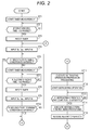
- the CPU 210 starts timer measurement (ST1).
- the CPU 210 checks whether a first specific time has passed or not after start of the timer measurement (ST2).
- the first specific time is the time which has been previously obtained by conducting a test, etc. and stored in the memory part 220 and also which is necessary for the temperature and pressure of the refrigerant in the refrigerant circuit 10 to stabilize after start of the heating operation (for example 10 min).
- the CPU 210 When the specific time has not passed (ST2-No), the CPU 210 returns the processing to ST2. When passed (ST2-Yes), it resets a timer (ST3), and inputs through a sensor input part 240 the outdoor air temperature To detected by the outdoor air temperature sensor 37 and the heat exchanger outlet temperature Teo detected by the refrigerant temperature sensor 35, and inputs the current operating unit number Ni of the indoor units 5a ⁇ 5b from the memory part 220 (ST4). When performing the processing of ST4, it stores the above-input outdoor air temperature To, heat exchanger outlet temperature Teo and operating unit number Ni of the indoor units 5a ⁇ 5b together into the memory part 220.
- the first frost forming condition is satisfied (ST5-Yes), that is, when the heat exchanger outlet temperature Teo is lower than -14°C, when the temperature difference between the outdoor air temperature To and the heat exchanger outlet temperature Teo is larger than 5°C, or when the duration time of the heating operation is longer than three hours, it advances the processing to ST 11.
- ST5-No that is, when the heat exchanger outlet temperature Teo is not lower than -14°C, when the temperature difference between the outdoor air temperature To and the heat exchanger outlet temperature Teo is not larger than 5°C, and when the duration time of the heating operation is not longer than three hours
- the second specific time is the time necessary to input the outdoor air temperature To detected by the outdoor air temperature sensor 37 and the heat exchanger outlet temperature Teo detected by the refrigerant temperature sensor 35, here five minutes.
- the second frost forming condition is satisfied or not (ST10). Specifically, it reads out the heat exchanger outlet temperature Teo stored in the memory part 220 in ST4 and ST9, and checks whether the heat exchanger outlet temperature Teo stored in ST9 is equal to or lower than -6°C or not, whether the drop rate of the heat exchanger outlet temperature calculated using the heat exchanger outlet temperature Teo stored in ST9 and the heat exchanger outlet temperature Teo stored in ST4 is equal to or more than 2°C/5min. or not, and whether, by comparing the operating unit numbers of indoor units 5a ⁇ 5c stored in ST4 and in ST9 with each other, the number of indoor units 5a ⁇ 5c in operation has increased or not.
- the defrosting operation preparation processing is a processing to be performed by the CPU 210 when switching the refrigerant circuit 10 for performing a defrosting operation; and, as described above, the CPU 210 stops the compressor 21 and outdoor fan 26 and, as shown in Fig. 1A , switches the four-way valve 22 into a state shown by a broken line, that is, so that the ports a and b of the four-way valve 22 communicate with each other and the ports c and d communicate with each other. And, after ending the processing of ST11, the CPU 210 resumes the compressor 21 to start the defrosting operation (ST12).
- the defrosting operation end condition is a condition which indicates that frost attached to the outdoor heat exchanger 23 is melted completely, for example, when the heat exchanger outlet temperature Teo input during the defrosting operation is 10°C or higher, or when 10 minutes or longer have passed after start of the defrosting operation in ST12.
- the heating operation resuming processing is a processing to be performed by the CPU 210 when switching the refrigerant circuit 10 for returning the defrosting operation to the heating operation; and, the CPU 210, after stopping the compressor 21, as shown in Fig. 1A , switches the four-way valve 22 into a state shown by a solid line, that is, so that the ports a and d of the four-way valve 22 communicate with each other and the ports b and c communicates with each other. And, the CPU 210, after ending the processing of ST14, resumes the compressor 21 and outdoor fan 26 to resume the heating operation (ST15), thereby returning the processing to ST4.
- FIG. 1A , 1B and 3 description is given of a second embodiment of the air conditioner of the invention using Figs. 1A , 1B and 3 .
- the structure and operation of the air conditioner of this embodiment are the same as the air conditioner of the first embodiment described by reference to Figs. 1A and 1B , and thus the specific description thereof is omitted.
- This embodiment is different from the first embodiment in that, instead of checking whether the number of indoor units 5a ⁇ 5c in operation in the second frost forming condition, the progress of sudden frost formation is detected by checking the increase rate of the number of rotations of the compressor 21.
- the increase rate of the number of rotations of the compressor 21 when the number of indoor units 5a ⁇ 5c in operation increases may be stored, that is, by conducting a test or the like, the increase rate of the number of rotations of the compressor 21 when the number of indoor units 5a ⁇ 5c in operation increases may be previously obtained and may be stored as a specific increase rate in the memory part 220.
- the increase rate of the number of rotations of the compressor 21 is equal to or lower than the specific increase rate, whether the number of indoor units in operation has increased or not can be checked.
- the number of rotations of the compressor 21 increases greatly.
- the specific increase rate may be an increase rate when the number of indoor units 5a ⁇ 5c increases by one during the heating operation, for example, 20%. Also, since the number of rotations of the compressor 21 is stored in the memory part 220, at the same timing as the outside air and heat exchanger outlet temperature are input, the CPU 210 confirms whether the number of rotations of the compressor 21 has varied or not and, when varied, stores a new number of rotations after varied into the memory part 220.
- the outdoor air temperature to be detected by the outdoor air temperature sensor 37 is expressed by To
- the heat exchanger outlet temperature to be detected by the refrigerant temperature sensor 35 is expressed by Teo
- the number of rotations of the compressor 21 is expressed by Rc.
- the CPU 210 After resetting a timer in ST23, the CPU 210 inputs through the sensor input part 240 the outdoor air temperature To detected by the outdoor air temperature sensor 37 and the heat exchanger outlet temperature Teo detected by the refrigerant temperature sensor 35, and also inputs the current number of rotations Rc of the compressor 21 from the memory part 220 (ST24).
- the CPU 210 when performing the processing of ST24, stores the thus-input the outdoor air temperature To, heat exchanger outlet temperature Teo and the number of rotations Rc of the compressor 21 together into the memory part 220.
- the CPU 210 advances the processings of ST24 and following steps and, after resetting the timer in ST28, inputs through the sensor input part 240 the outdoor air temperature To detected by the outdoor air temperature sensor 37 and the heat exchanger outlet temperature Teo detected by the refrigerant temperature sensor 35, and also inputs the current number of rotations Rc of the compressor 21 from the memory part 220 (ST29).
- it stores the thus-input the outdoor air temperature To, heat exchanger outlet temperature Teo and the number of rotations Rc of the compressor 21 together into the memory part 220.
- the CPU 210 checks whether the second frost forming condition is satisfied or not (ST30). Specifically, it reads out the heat exchanger outlet temperature Teo stored into the memory part 220 in ST24 and ST29, and checks whether the heat exchanger outlet temperature Teo stored in ST29 is equal to or lower than -6°C or not, whether the drop rate of the heat exchanger outlet temperature calculated using the heat exchanger outlet temperature Teo stored in ST29 and the heat exchanger outlet temperature Teo stored in ST24 is 2°C/5min. or larger or not, and whether the increase rate of the number of rotations of the compressor 21 calculated using the number of rotations Rc of the compressor 21 stored into the memory part 220 in ST24 and ST29 is 20% or lower or not.
- the CPU 210 When not satisfied (ST30-No), that is, when the heat exchanger outlet temperature Teo is higher than -6°C or the drop rate of the heat exchanger outlet temperature Teo is less than 2°C/5min. or the increase rate of the number of rotations of the compressor 21 is higher than 20%, the CPU 210 returns the processing to ST25.
- the CPU 210 executes a defrosting operation preparation processing (ST31).
Landscapes
- Engineering & Computer Science (AREA)
- General Engineering & Computer Science (AREA)
- Mechanical Engineering (AREA)
- Physics & Mathematics (AREA)
- Thermal Sciences (AREA)
- Chemical & Material Sciences (AREA)
- Combustion & Propulsion (AREA)
- Life Sciences & Earth Sciences (AREA)
- Atmospheric Sciences (AREA)
- General Physics & Mathematics (AREA)
- Automation & Control Theory (AREA)
- Air Conditioning Control Device (AREA)
Applications Claiming Priority (1)
| Application Number | Priority Date | Filing Date | Title |
|---|---|---|---|
| JP2015042533A JP2016161256A (ja) | 2015-03-04 | 2015-03-04 | 空気調和装置 |
Publications (3)
| Publication Number | Publication Date |
|---|---|
| EP3064867A2 true EP3064867A2 (de) | 2016-09-07 |
| EP3064867A3 EP3064867A3 (de) | 2016-12-21 |
| EP3064867B1 EP3064867B1 (de) | 2022-03-30 |
Family
ID=55443184
Family Applications (1)
| Application Number | Title | Priority Date | Filing Date |
|---|---|---|---|
| EP16157838.0A Active EP3064867B1 (de) | 2015-03-04 | 2016-02-29 | Klimaanlage |
Country Status (6)
| Country | Link |
|---|---|
| US (1) | US10024589B2 (de) |
| EP (1) | EP3064867B1 (de) |
| JP (1) | JP2016161256A (de) |
| CN (1) | CN105937796B (de) |
| AU (1) | AU2016201373A1 (de) |
| ES (1) | ES2912884T3 (de) |
Cited By (3)
| Publication number | Priority date | Publication date | Assignee | Title |
|---|---|---|---|---|
| CN108592299A (zh) * | 2018-05-03 | 2018-09-28 | 广东美的暖通设备有限公司 | 化霜控制方法及系统 |
| EP3885676A4 (de) * | 2018-11-19 | 2022-08-10 | Daikin Industries, Ltd. | Kühlmittelkreislauf, kühlmittelmengenbestimmungssystem und kühlmittelmengenbestimmungsverfahren |
| US12264831B2 (en) | 2020-12-17 | 2025-04-01 | Gree Electric Appliances, Inc. Of Zhuhai | Defrosting control method and device, and multi-split air conditioner |
Families Citing this family (16)
| Publication number | Priority date | Publication date | Assignee | Title |
|---|---|---|---|---|
| JP6559332B2 (ja) * | 2016-04-14 | 2019-08-14 | 三菱電機株式会社 | 冷凍サイクル装置 |
| US10731905B2 (en) * | 2016-06-21 | 2020-08-04 | Mitsubishi Electric Corporation | Defrosting determination device, defrosting control device, and air conditioner |
| KR102725964B1 (ko) | 2016-11-10 | 2024-11-05 | 엘지전자 주식회사 | 냉장고 및 냉장고의 제어 방법 |
| CN110749037B (zh) * | 2018-07-23 | 2021-09-07 | 大金工业株式会社 | 空调器的蒸发器的自动清洗方法和装置 |
| CN109458700B (zh) * | 2018-11-08 | 2020-08-25 | 珠海格力电器股份有限公司 | 多联机化霜方法、装置、存储介质、计算机设备及空调 |
| CN110469984B (zh) * | 2019-07-26 | 2022-09-06 | 青岛海尔空调器有限总公司 | 用于空调除霜的控制方法、装置及空调 |
| CN110470004B (zh) * | 2019-08-02 | 2022-09-02 | 青岛海尔空调器有限总公司 | 用于空调除霜的控制方法及装置、空调 |
| CN110553436B (zh) * | 2019-08-20 | 2021-08-06 | 广东纽恩泰新能源科技发展有限公司 | 一种热泵结霜积灰的判定方法 |
| JP7258163B2 (ja) * | 2019-09-09 | 2023-04-14 | 三菱電機株式会社 | 冷凍サイクル装置 |
| CN110736210B (zh) * | 2019-09-26 | 2021-10-29 | 青岛海尔空调器有限总公司 | 用于空调除霜的控制方法、控制装置及空调 |
| CN111561761B (zh) * | 2020-04-13 | 2022-09-09 | 海信空调有限公司 | 一种延缓空调系统结霜的控制方法 |
| CN113883661B (zh) * | 2020-07-03 | 2022-08-19 | 青岛海尔空调电子有限公司 | 用于多联机空调系统的除霜控制方法 |
| CN113154636B (zh) * | 2021-04-25 | 2022-05-17 | 珠海格力电器股份有限公司 | 空调器化霜控制方法、装置、存储介质和空调器 |
| CN113203182B (zh) * | 2021-04-26 | 2022-12-27 | 广东美的暖通设备有限公司 | 空调器的化霜控制方法、装置、空调器和存储介质 |
| US12222144B2 (en) | 2021-07-19 | 2025-02-11 | Carrier Corporation | Variable capacity defrost |
| JP7295318B1 (ja) | 2022-09-20 | 2023-06-20 | 日立ジョンソンコントロールズ空調株式会社 | 空気調和機 |
Citations (1)
| Publication number | Priority date | Publication date | Assignee | Title |
|---|---|---|---|---|
| JP2009228928A (ja) | 2008-03-19 | 2009-10-08 | Daikin Ind Ltd | 空気調和装置 |
Family Cites Families (32)
| Publication number | Priority date | Publication date | Assignee | Title |
|---|---|---|---|---|
| JPS58148333A (ja) * | 1982-02-26 | 1983-09-03 | Mitsubishi Heavy Ind Ltd | 空気熱源ヒ−トポンプの除霜方法 |
| JPH0452441A (ja) * | 1990-06-18 | 1992-02-20 | Sanyo Electric Co Ltd | ヒートポンプ式空気調和機の着霜検知方式 |
| US5257506A (en) * | 1991-03-22 | 1993-11-02 | Carrier Corporation | Defrost control |
| US5319943A (en) * | 1993-01-25 | 1994-06-14 | Copeland Corporation | Frost/defrost control system for heat pump |
| JP3893676B2 (ja) * | 1996-08-08 | 2007-03-14 | 株式会社日立製作所 | 空気調和装置 |
| US5809789A (en) * | 1997-05-07 | 1998-09-22 | Baker; Philip L. | Refrigeration module |
| KR100225640B1 (ko) * | 1997-06-27 | 1999-10-15 | 윤종용 | 공기조화기의 제상제어방법 |
| JP3888403B2 (ja) * | 1997-12-18 | 2007-03-07 | 株式会社富士通ゼネラル | 空気調和機の制御方法およびその装置 |
| US5927083A (en) * | 1998-03-09 | 1999-07-27 | Carrier Corporation | Compressor cycle dependent defrost control |
| JPH11325671A (ja) * | 1998-05-20 | 1999-11-26 | Fujitsu General Ltd | 空気調和機の制御方法 |
| JP2000130825A (ja) * | 1998-10-26 | 2000-05-12 | Toshiba Kyaria Kk | 空気調和機の室外機用駆動制御ユニット |
| CN1215295C (zh) * | 2001-04-18 | 2005-08-17 | 广东科龙电器股份有限公司 | 一种空调机除霜方法 |
| JP2003042521A (ja) * | 2001-07-26 | 2003-02-13 | Hitachi Ltd | 空気調和装置 |
| WO2007013382A1 (ja) * | 2005-07-26 | 2007-02-01 | Mitsubishi Electric Corporation | 冷凍空調装置 |
| JP2008215734A (ja) * | 2007-03-06 | 2008-09-18 | Hitachi Appliances Inc | マルチ式空気調和機 |
| JP4978777B2 (ja) * | 2007-03-15 | 2012-07-18 | アイシン精機株式会社 | 冷凍サイクル装置 |
| WO2009093297A1 (ja) * | 2008-01-21 | 2009-07-30 | Mitsubishi Electric Corporation | ヒートポンプ装置及びこのヒートポンプ装置を搭載した空気調和機又は給湯器 |
| US20110146339A1 (en) * | 2008-10-29 | 2011-06-23 | Koji Yamashita | Air-conditioning apparatus |
| KR101608538B1 (ko) * | 2009-12-31 | 2016-04-01 | 엘지전자 주식회사 | 냉매사이클 연동 물 순환 시스템 |
| JP5570531B2 (ja) * | 2010-01-26 | 2014-08-13 | 三菱電機株式会社 | ヒートポンプ装置 |
| JP5053430B2 (ja) * | 2010-10-05 | 2012-10-17 | シャープ株式会社 | 空気調和機 |
| JP5708249B2 (ja) * | 2011-05-27 | 2015-04-30 | 株式会社ノーリツ | ヒートポンプ給湯装置 |
| JP2013155964A (ja) * | 2012-01-31 | 2013-08-15 | Fujitsu General Ltd | 空気調和装置 |
| JP2013200085A (ja) * | 2012-03-26 | 2013-10-03 | Fujitsu General Ltd | 空気調和機 |
| JP5933003B2 (ja) * | 2012-07-20 | 2016-06-08 | 三菱電機株式会社 | 空気調和装置 |
| JP2014163548A (ja) * | 2013-02-22 | 2014-09-08 | Fujitsu General Ltd | 空気調和装置 |
| KR102129297B1 (ko) * | 2013-07-29 | 2020-07-03 | 삼성전자주식회사 | 공기 조화기 및 그 제어 방법 |
| JP5574028B1 (ja) * | 2013-07-31 | 2014-08-20 | 株式会社富士通ゼネラル | 空気調和装置 |
| JP6201872B2 (ja) * | 2014-04-16 | 2017-09-27 | 三菱電機株式会社 | 空気調和機 |
| JP6486335B2 (ja) * | 2014-04-22 | 2019-03-20 | 日立ジョンソンコントロールズ空調株式会社 | 空気調和機及びその除霜運転方法 |
| JP6257801B2 (ja) * | 2014-11-04 | 2018-01-10 | 三菱電機株式会社 | 冷凍サイクル装置及び冷凍サイクル装置の異常検知システム |
| JP6397050B2 (ja) * | 2014-11-26 | 2018-09-26 | 日立ジョンソンコントロールズ空調株式会社 | 空気調和機 |
-
2015
- 2015-03-04 JP JP2015042533A patent/JP2016161256A/ja active Pending
-
2016
- 2016-02-29 EP EP16157838.0A patent/EP3064867B1/de active Active
- 2016-02-29 ES ES16157838T patent/ES2912884T3/es active Active
- 2016-03-01 CN CN201610115600.1A patent/CN105937796B/zh active Active
- 2016-03-02 AU AU2016201373A patent/AU2016201373A1/en not_active Abandoned
- 2016-03-03 US US15/059,504 patent/US10024589B2/en active Active
Patent Citations (1)
| Publication number | Priority date | Publication date | Assignee | Title |
|---|---|---|---|---|
| JP2009228928A (ja) | 2008-03-19 | 2009-10-08 | Daikin Ind Ltd | 空気調和装置 |
Cited By (3)
| Publication number | Priority date | Publication date | Assignee | Title |
|---|---|---|---|---|
| CN108592299A (zh) * | 2018-05-03 | 2018-09-28 | 广东美的暖通设备有限公司 | 化霜控制方法及系统 |
| EP3885676A4 (de) * | 2018-11-19 | 2022-08-10 | Daikin Industries, Ltd. | Kühlmittelkreislauf, kühlmittelmengenbestimmungssystem und kühlmittelmengenbestimmungsverfahren |
| US12264831B2 (en) | 2020-12-17 | 2025-04-01 | Gree Electric Appliances, Inc. Of Zhuhai | Defrosting control method and device, and multi-split air conditioner |
Also Published As
| Publication number | Publication date |
|---|---|
| AU2016201373A1 (en) | 2016-09-22 |
| JP2016161256A (ja) | 2016-09-05 |
| CN105937796A (zh) | 2016-09-14 |
| ES2912884T3 (es) | 2022-05-30 |
| CN105937796B (zh) | 2019-12-31 |
| EP3064867A3 (de) | 2016-12-21 |
| US20160258661A1 (en) | 2016-09-08 |
| EP3064867B1 (de) | 2022-03-30 |
| US10024589B2 (en) | 2018-07-17 |
Similar Documents
| Publication | Publication Date | Title |
|---|---|---|
| EP3064867B1 (de) | Klimaanlage | |
| EP3032193B1 (de) | Klimaanlagenvorrichtung | |
| EP2840324B1 (de) | Klimaanlagenaußeneinheit und Klimaanlage | |
| EP3021053B1 (de) | Klimaanlage | |
| EP3029390B1 (de) | Klimaanlage | |
| EP3054230B1 (de) | Klimaanlage | |
| EP3190357B1 (de) | Klimaanlage | |
| US9739521B2 (en) | Air conditioning apparatus | |
| EP3581855B1 (de) | Klimatisierungsvorrichtung | |
| EP3045830A1 (de) | Klimaanlagenvorrichtung | |
| JP6819112B2 (ja) | 空気調和装置 | |
| JP6822177B2 (ja) | 空気調和装置 | |
| EP3943824B1 (de) | Vorrichtungsbeurteilungssystem und vorrichtungsbeurteilungsverfahren | |
| JP7009808B2 (ja) | 空気調和装置 | |
| JP7408942B2 (ja) | 空気調和装置 | |
| JP2018115805A (ja) | 空気調和装置 |
Legal Events
| Date | Code | Title | Description |
|---|---|---|---|
| PUAI | Public reference made under article 153(3) epc to a published international application that has entered the european phase |
Free format text: ORIGINAL CODE: 0009012 |
|
| AK | Designated contracting states |
Kind code of ref document: A2 Designated state(s): AL AT BE BG CH CY CZ DE DK EE ES FI FR GB GR HR HU IE IS IT LI LT LU LV MC MK MT NL NO PL PT RO RS SE SI SK SM TR |
|
| AX | Request for extension of the european patent |
Extension state: BA ME |
|
| PUAL | Search report despatched |
Free format text: ORIGINAL CODE: 0009013 |
|
| AK | Designated contracting states |
Kind code of ref document: A3 Designated state(s): AL AT BE BG CH CY CZ DE DK EE ES FI FR GB GR HR HU IE IS IT LI LT LU LV MC MK MT NL NO PL PT RO RS SE SI SK SM TR |
|
| AX | Request for extension of the european patent |
Extension state: BA ME |
|
| RIC1 | Information provided on ipc code assigned before grant |
Ipc: F25B 13/00 20060101AFI20161114BHEP Ipc: F25B 49/02 20060101ALN20161114BHEP Ipc: F25B 47/02 20060101ALI20161114BHEP |
|
| STAA | Information on the status of an ep patent application or granted ep patent |
Free format text: STATUS: REQUEST FOR EXAMINATION WAS MADE |
|
| 17P | Request for examination filed |
Effective date: 20170614 |
|
| RBV | Designated contracting states (corrected) |
Designated state(s): AL AT BE BG CH CY CZ DE DK EE ES FI FR GB GR HR HU IE IS IT LI LT LU LV MC MK MT NL NO PL PT RO RS SE SI SK SM TR |
|
| GRAP | Despatch of communication of intention to grant a patent |
Free format text: ORIGINAL CODE: EPIDOSNIGR1 |
|
| STAA | Information on the status of an ep patent application or granted ep patent |
Free format text: STATUS: GRANT OF PATENT IS INTENDED |
|
| RIC1 | Information provided on ipc code assigned before grant |
Ipc: F25B 49/02 20060101ALN20210916BHEP Ipc: F25B 47/02 20060101ALI20210916BHEP Ipc: F25B 13/00 20060101AFI20210916BHEP |
|
| INTG | Intention to grant announced |
Effective date: 20210930 |
|
| RIN1 | Information on inventor provided before grant (corrected) |
Inventor name: TAKI, EIJI |
|
| GRAS | Grant fee paid |
Free format text: ORIGINAL CODE: EPIDOSNIGR3 |
|
| GRAA | (expected) grant |
Free format text: ORIGINAL CODE: 0009210 |
|
| STAA | Information on the status of an ep patent application or granted ep patent |
Free format text: STATUS: THE PATENT HAS BEEN GRANTED |
|
| AK | Designated contracting states |
Kind code of ref document: B1 Designated state(s): AL AT BE BG CH CY CZ DE DK EE ES FI FR GB GR HR HU IE IS IT LI LT LU LV MC MK MT NL NO PL PT RO RS SE SI SK SM TR |
|
| REG | Reference to a national code |
Ref country code: GB Ref legal event code: FG4D |
|
| REG | Reference to a national code |
Ref country code: CH Ref legal event code: EP |
|
| REG | Reference to a national code |
Ref country code: DE Ref legal event code: R096 Ref document number: 602016070428 Country of ref document: DE |
|
| REG | Reference to a national code |
Ref country code: AT Ref legal event code: REF Ref document number: 1479539 Country of ref document: AT Kind code of ref document: T Effective date: 20220415 |
|
| REG | Reference to a national code |
Ref country code: IE Ref legal event code: FG4D |
|
| REG | Reference to a national code |
Ref country code: ES Ref legal event code: FG2A Ref document number: 2912884 Country of ref document: ES Kind code of ref document: T3 Effective date: 20220530 |
|
| REG | Reference to a national code |
Ref country code: LT Ref legal event code: MG9D |
|
| PG25 | Lapsed in a contracting state [announced via postgrant information from national office to epo] |
Ref country code: SE Free format text: LAPSE BECAUSE OF FAILURE TO SUBMIT A TRANSLATION OF THE DESCRIPTION OR TO PAY THE FEE WITHIN THE PRESCRIBED TIME-LIMIT Effective date: 20220330 Ref country code: RS Free format text: LAPSE BECAUSE OF FAILURE TO SUBMIT A TRANSLATION OF THE DESCRIPTION OR TO PAY THE FEE WITHIN THE PRESCRIBED TIME-LIMIT Effective date: 20220330 Ref country code: NO Free format text: LAPSE BECAUSE OF FAILURE TO SUBMIT A TRANSLATION OF THE DESCRIPTION OR TO PAY THE FEE WITHIN THE PRESCRIBED TIME-LIMIT Effective date: 20220630 Ref country code: LT Free format text: LAPSE BECAUSE OF FAILURE TO SUBMIT A TRANSLATION OF THE DESCRIPTION OR TO PAY THE FEE WITHIN THE PRESCRIBED TIME-LIMIT Effective date: 20220330 Ref country code: HR Free format text: LAPSE BECAUSE OF FAILURE TO SUBMIT A TRANSLATION OF THE DESCRIPTION OR TO PAY THE FEE WITHIN THE PRESCRIBED TIME-LIMIT Effective date: 20220330 Ref country code: BG Free format text: LAPSE BECAUSE OF FAILURE TO SUBMIT A TRANSLATION OF THE DESCRIPTION OR TO PAY THE FEE WITHIN THE PRESCRIBED TIME-LIMIT Effective date: 20220630 |
|
| REG | Reference to a national code |
Ref country code: NL Ref legal event code: MP Effective date: 20220330 |
|
| REG | Reference to a national code |
Ref country code: AT Ref legal event code: MK05 Ref document number: 1479539 Country of ref document: AT Kind code of ref document: T Effective date: 20220330 |
|
| PG25 | Lapsed in a contracting state [announced via postgrant information from national office to epo] |
Ref country code: LV Free format text: LAPSE BECAUSE OF FAILURE TO SUBMIT A TRANSLATION OF THE DESCRIPTION OR TO PAY THE FEE WITHIN THE PRESCRIBED TIME-LIMIT Effective date: 20220330 Ref country code: GR Free format text: LAPSE BECAUSE OF FAILURE TO SUBMIT A TRANSLATION OF THE DESCRIPTION OR TO PAY THE FEE WITHIN THE PRESCRIBED TIME-LIMIT Effective date: 20220701 Ref country code: FI Free format text: LAPSE BECAUSE OF FAILURE TO SUBMIT A TRANSLATION OF THE DESCRIPTION OR TO PAY THE FEE WITHIN THE PRESCRIBED TIME-LIMIT Effective date: 20220330 |
|
| PG25 | Lapsed in a contracting state [announced via postgrant information from national office to epo] |
Ref country code: NL Free format text: LAPSE BECAUSE OF FAILURE TO SUBMIT A TRANSLATION OF THE DESCRIPTION OR TO PAY THE FEE WITHIN THE PRESCRIBED TIME-LIMIT Effective date: 20220330 |
|
| PG25 | Lapsed in a contracting state [announced via postgrant information from national office to epo] |
Ref country code: SM Free format text: LAPSE BECAUSE OF FAILURE TO SUBMIT A TRANSLATION OF THE DESCRIPTION OR TO PAY THE FEE WITHIN THE PRESCRIBED TIME-LIMIT Effective date: 20220330 Ref country code: SK Free format text: LAPSE BECAUSE OF FAILURE TO SUBMIT A TRANSLATION OF THE DESCRIPTION OR TO PAY THE FEE WITHIN THE PRESCRIBED TIME-LIMIT Effective date: 20220330 Ref country code: RO Free format text: LAPSE BECAUSE OF FAILURE TO SUBMIT A TRANSLATION OF THE DESCRIPTION OR TO PAY THE FEE WITHIN THE PRESCRIBED TIME-LIMIT Effective date: 20220330 Ref country code: PT Free format text: LAPSE BECAUSE OF FAILURE TO SUBMIT A TRANSLATION OF THE DESCRIPTION OR TO PAY THE FEE WITHIN THE PRESCRIBED TIME-LIMIT Effective date: 20220801 Ref country code: EE Free format text: LAPSE BECAUSE OF FAILURE TO SUBMIT A TRANSLATION OF THE DESCRIPTION OR TO PAY THE FEE WITHIN THE PRESCRIBED TIME-LIMIT Effective date: 20220330 Ref country code: CZ Free format text: LAPSE BECAUSE OF FAILURE TO SUBMIT A TRANSLATION OF THE DESCRIPTION OR TO PAY THE FEE WITHIN THE PRESCRIBED TIME-LIMIT Effective date: 20220330 Ref country code: AT Free format text: LAPSE BECAUSE OF FAILURE TO SUBMIT A TRANSLATION OF THE DESCRIPTION OR TO PAY THE FEE WITHIN THE PRESCRIBED TIME-LIMIT Effective date: 20220330 |
|
| PG25 | Lapsed in a contracting state [announced via postgrant information from national office to epo] |
Ref country code: PL Free format text: LAPSE BECAUSE OF FAILURE TO SUBMIT A TRANSLATION OF THE DESCRIPTION OR TO PAY THE FEE WITHIN THE PRESCRIBED TIME-LIMIT Effective date: 20220330 Ref country code: IS Free format text: LAPSE BECAUSE OF FAILURE TO SUBMIT A TRANSLATION OF THE DESCRIPTION OR TO PAY THE FEE WITHIN THE PRESCRIBED TIME-LIMIT Effective date: 20220730 Ref country code: AL Free format text: LAPSE BECAUSE OF FAILURE TO SUBMIT A TRANSLATION OF THE DESCRIPTION OR TO PAY THE FEE WITHIN THE PRESCRIBED TIME-LIMIT Effective date: 20220330 |
|
| REG | Reference to a national code |
Ref country code: DE Ref legal event code: R097 Ref document number: 602016070428 Country of ref document: DE |
|
| PG25 | Lapsed in a contracting state [announced via postgrant information from national office to epo] |
Ref country code: DK Free format text: LAPSE BECAUSE OF FAILURE TO SUBMIT A TRANSLATION OF THE DESCRIPTION OR TO PAY THE FEE WITHIN THE PRESCRIBED TIME-LIMIT Effective date: 20220330 |
|
| PLBE | No opposition filed within time limit |
Free format text: ORIGINAL CODE: 0009261 |
|
| STAA | Information on the status of an ep patent application or granted ep patent |
Free format text: STATUS: NO OPPOSITION FILED WITHIN TIME LIMIT |
|
| 26N | No opposition filed |
Effective date: 20230103 |
|
| PG25 | Lapsed in a contracting state [announced via postgrant information from national office to epo] |
Ref country code: SI Free format text: LAPSE BECAUSE OF FAILURE TO SUBMIT A TRANSLATION OF THE DESCRIPTION OR TO PAY THE FEE WITHIN THE PRESCRIBED TIME-LIMIT Effective date: 20220330 |
|
| PG25 | Lapsed in a contracting state [announced via postgrant information from national office to epo] |
Ref country code: MC Free format text: LAPSE BECAUSE OF FAILURE TO SUBMIT A TRANSLATION OF THE DESCRIPTION OR TO PAY THE FEE WITHIN THE PRESCRIBED TIME-LIMIT Effective date: 20220330 |
|
| REG | Reference to a national code |
Ref country code: CH Ref legal event code: PL |
|
| REG | Reference to a national code |
Ref country code: BE Ref legal event code: MM Effective date: 20230228 |
|
| PG25 | Lapsed in a contracting state [announced via postgrant information from national office to epo] |
Ref country code: LU Free format text: LAPSE BECAUSE OF NON-PAYMENT OF DUE FEES Effective date: 20230228 Ref country code: LI Free format text: LAPSE BECAUSE OF NON-PAYMENT OF DUE FEES Effective date: 20230228 Ref country code: CH Free format text: LAPSE BECAUSE OF NON-PAYMENT OF DUE FEES Effective date: 20230228 |
|
| REG | Reference to a national code |
Ref country code: IE Ref legal event code: MM4A |
|
| PG25 | Lapsed in a contracting state [announced via postgrant information from national office to epo] |
Ref country code: IE Free format text: LAPSE BECAUSE OF NON-PAYMENT OF DUE FEES Effective date: 20230228 |
|
| PG25 | Lapsed in a contracting state [announced via postgrant information from national office to epo] |
Ref country code: BE Free format text: LAPSE BECAUSE OF NON-PAYMENT OF DUE FEES Effective date: 20230228 |
|
| PG25 | Lapsed in a contracting state [announced via postgrant information from national office to epo] |
Ref country code: CY Free format text: LAPSE BECAUSE OF FAILURE TO SUBMIT A TRANSLATION OF THE DESCRIPTION OR TO PAY THE FEE WITHIN THE PRESCRIBED TIME-LIMIT; INVALID AB INITIO Effective date: 20160229 |
|
| PG25 | Lapsed in a contracting state [announced via postgrant information from national office to epo] |
Ref country code: HU Free format text: LAPSE BECAUSE OF FAILURE TO SUBMIT A TRANSLATION OF THE DESCRIPTION OR TO PAY THE FEE WITHIN THE PRESCRIBED TIME-LIMIT; INVALID AB INITIO Effective date: 20160229 |
|
| PG25 | Lapsed in a contracting state [announced via postgrant information from national office to epo] |
Ref country code: TR Free format text: LAPSE BECAUSE OF FAILURE TO SUBMIT A TRANSLATION OF THE DESCRIPTION OR TO PAY THE FEE WITHIN THE PRESCRIBED TIME-LIMIT Effective date: 20220330 |
|
| PGFP | Annual fee paid to national office [announced via postgrant information from national office to epo] |
Ref country code: GB Payment date: 20260218 Year of fee payment: 11 |
|
| PGFP | Annual fee paid to national office [announced via postgrant information from national office to epo] |
Ref country code: ES Payment date: 20260319 Year of fee payment: 11 |
|
| PGFP | Annual fee paid to national office [announced via postgrant information from national office to epo] |
Ref country code: DE Payment date: 20260217 Year of fee payment: 11 |
|
| PGFP | Annual fee paid to national office [announced via postgrant information from national office to epo] |
Ref country code: IT Payment date: 20260227 Year of fee payment: 11 |
|
| PGFP | Annual fee paid to national office [announced via postgrant information from national office to epo] |
Ref country code: FR Payment date: 20260213 Year of fee payment: 11 |