EP3064409A1 - Eisenbahnwaggon-bremsanlage - Google Patents
Eisenbahnwaggon-bremsanlage Download PDFInfo
- Publication number
- EP3064409A1 EP3064409A1 EP14856882.7A EP14856882A EP3064409A1 EP 3064409 A1 EP3064409 A1 EP 3064409A1 EP 14856882 A EP14856882 A EP 14856882A EP 3064409 A1 EP3064409 A1 EP 3064409A1
- Authority
- EP
- European Patent Office
- Prior art keywords
- air
- brake
- pressure
- emergency
- vehicle
- Prior art date
- Legal status (The legal status is an assumption and is not a legal conclusion. Google has not performed a legal analysis and makes no representation as to the accuracy of the status listed.)
- Granted
Links
- 238000004140 cleaning Methods 0.000 claims description 129
- 230000002159 abnormal effect Effects 0.000 description 7
- 230000001105 regulatory effect Effects 0.000 description 7
- 238000005259 measurement Methods 0.000 description 5
- 230000000694 effects Effects 0.000 description 4
- 239000012530 fluid Substances 0.000 description 4
- 230000000052 comparative effect Effects 0.000 description 3
- 238000010586 diagram Methods 0.000 description 3
- 238000001514 detection method Methods 0.000 description 2
- 230000005611 electricity Effects 0.000 description 2
- 238000009434 installation Methods 0.000 description 2
- 230000001172 regenerating effect Effects 0.000 description 2
- 238000012790 confirmation Methods 0.000 description 1
- 230000003111 delayed effect Effects 0.000 description 1
- 239000011347 resin Substances 0.000 description 1
- 229920005989 resin Polymers 0.000 description 1
Images


Classifications
-
- B—PERFORMING OPERATIONS; TRANSPORTING
- B60—VEHICLES IN GENERAL
- B60T—VEHICLE BRAKE CONTROL SYSTEMS OR PARTS THEREOF; BRAKE CONTROL SYSTEMS OR PARTS THEREOF, IN GENERAL; ARRANGEMENT OF BRAKING ELEMENTS ON VEHICLES IN GENERAL; PORTABLE DEVICES FOR PREVENTING UNWANTED MOVEMENT OF VEHICLES; VEHICLE MODIFICATIONS TO FACILITATE COOLING OF BRAKES
- B60T13/00—Transmitting braking action from initiating means to ultimate brake actuator with power assistance or drive; Brake systems incorporating such transmitting means, e.g. air-pressure brake systems
- B60T13/10—Transmitting braking action from initiating means to ultimate brake actuator with power assistance or drive; Brake systems incorporating such transmitting means, e.g. air-pressure brake systems with fluid assistance, drive, or release
- B60T13/66—Electrical control in fluid-pressure brake systems
- B60T13/665—Electrical control in fluid-pressure brake systems the systems being specially adapted for transferring two or more command signals, e.g. railway systems
-
- B—PERFORMING OPERATIONS; TRANSPORTING
- B60—VEHICLES IN GENERAL
- B60T—VEHICLE BRAKE CONTROL SYSTEMS OR PARTS THEREOF; BRAKE CONTROL SYSTEMS OR PARTS THEREOF, IN GENERAL; ARRANGEMENT OF BRAKING ELEMENTS ON VEHICLES IN GENERAL; PORTABLE DEVICES FOR PREVENTING UNWANTED MOVEMENT OF VEHICLES; VEHICLE MODIFICATIONS TO FACILITATE COOLING OF BRAKES
- B60T17/00—Component parts, details, or accessories of power brake systems not covered by groups B60T8/00, B60T13/00 or B60T15/00, or presenting other characteristic features
- B60T17/18—Safety devices; Monitoring
- B60T17/22—Devices for monitoring or checking brake systems; Signal devices
- B60T17/228—Devices for monitoring or checking brake systems; Signal devices for railway vehicles
Definitions
- the prevent invention relates to a vehicle brake apparatus.
- Patent Document 1 discloses a brake system for the Shinkansen railroad vehicle or a conventional railroad vehicle, which includes an emergency brake control device supplying a pressure fluid to an actuator that is a brake cylinder.
- the brake system disclosed in Patent Document 1 includes a brake control device; an emergency pressure generation unit; a double check valve; and a pressure intensifier cylinder (brake cylinder).
- the brake control device receives an emergency brake command output from an upper system, and supplies a pressure fluid (hereinafter, referred to as first compressed air), which has a pressure (first air pressure) corresponding to the emergency brake command, to the double check valve.
- the pressure generation unit includes a pressure regulating valve and a solenoid valve.
- the pressure regulating valve regulates the pressure of a pressure fluid (hereinafter, referred to as second compressed air), which is supplied from an air source different from the brake control device, to a predetermined second air pressure, and supplies the second compressed air having the second air pressure to the solenoid valve.
- second compressed air a pressure fluid
- the state of the solenoid valve is changed from a closed state to an open state only when the solenoid valve receives the emergency brake command, and the solenoid valve supplies the second compressed air to the double check valve.
- the double check valve selectively supplies one compressed air having a higher pressure among the first compressed air supplied from the brake control device and the second compressed air supplied from the pressure generation unit to the pressure intensifier cylinder.
- the pressure intensifier cylinder transforms the pressure of the compressed air supplied from the double check valve into an oil pressure.
- the oil pressure presses brake pads against a brake disc such that a braking force is applied to the brake disc.
- Patent Document 1 Japanese Unexamined Patent Application, First Publication No. 2012-11984
- the pressure generation unit is additionally provided which includes the pressure regulating valve that regulates the air pressure of the second compressed air supplied from the air source to a predetermined emergency air pressure (the second air pressure).
- the brake system disclosed in Patent Document 1 adopts a configuration in which the length of a pipeline between the pressure generation unit and the double check valve (switching valve) is short.
- the pressure generation unit is additionally provided in the brake operation system, the length of the pipeline between the pressure generation unit and the double check valve is still long.
- the length of time (free running time) required from the generation of an emergency brake command until the internal pressure of the pressure intensifier cylinder reaches a specified value (lower limit value of the pressure required to generate an effective braking force: for example, 63% of the normal value of the first air pressure) is still long, and a problem such as an emergency brake operation being delayed (the free running distance of a vehicle is increased) has not yet been solved.
- the present invention is made in light of this problem, and an object of the present invention is to provide a vehicle brake apparatus capable of reducing the free running time of a vehicle during emergency braking by adopting a simple configuration.
- the present invention adopts the following measures so as to solve this problem and achieve this object.
- the vehicle brake apparatus it is possible to reduce the length of a pipeline between the second tank and the brake cylinder.
- the emergency brake operation since the second compressed air inside the second tank is quickly supplied as the emergency brake air to the brake cylinder via the short pipeline, the internal pressure of the brake cylinder can be quickly increased to a specified value (lower limit value of the pressure required to generate an effective braking force). Accordingly, it is possible to reduce the free running time from when the emergency brake operation is performed until the internal pressure of the brake cylinder reaches the specified value.
- the vehicle brake apparatus according to (1) is capable of reducing the free running time of the vehicle during emergency braking by adopting a simple configuration.
- the opening and closing valve opens, and then the second compressed air inside the second tank is supplied as the emergency brake air to the switching valve.
- One compressed air having a higher pressure among the brake control air and the emergency brake air is supplied to the brake cylinder via the switching valve. Accordingly, in a case where the pressure of the brake control air supplied from the first pressure control device is still low, the emergency brake air supplied from the second tank is preferentially supplied to the brake cylinder. As a result, it is possible to quickly increase the internal pressure of the brake cylinder to the specified value, and it is possible to effectively apply the braking force to the wheels for an emergency stop.
- the vehicle brake apparatus when the emergency brake operation is performed, even if the second compressed air inside the second tank is preferentially supplied as the emergency brake air to the brake cylinder, the internal pressure of the brake cylinder is not abnormally increased. Accordingly, it is possible to prevent the occurrence of trouble such as the wheels being locked and slipping during emergency braking.
- the vehicle brake apparatus since an existing auxiliary air tank installed on the bogie is used as the second tank, and the second compressed air, which is primarily supplied from the auxiliary air tank only to the air spring, is also supplied as the emergency brake air to the brake cylinder, it is not necessary to provide extra equipment such as the air source, the pressure regulating valve, and the control device thereof which are additionally provided in the conventional brake system. For this reason, it is possible to reduce the free running time of the vehicle during emergency braking by implementation of a simple configuration.
- the tread cleaning cylinder is operated within a very short period of time from the starting of the emergency brake operation such that the abrasive block is capable of cleaning the corresponding wheel tread. As a result, it is possible to effectively perform the subsequent emergency brake operation.
- the auxiliary air tank (second tank) is used as a supply source of the emergency cleaning air which supplies the second compressed air to the air spring between the bogie and the vehicle body, it is not necessary to provide special equipment in a conventional tread cleaning system. For this reason, the second compressed air inside the auxiliary air tank is supplied as the emergency cleaning air to the tread cleaning cylinder such that the internal pressure of the tread cleaning cylinder can be quickly increased to a specified value (lower limit value of the pressure required for the abrasive block to effectively clean the corresponding wheel tread).
- auxiliary air tank which supplies the second compressed air to the air spring between the vehicle body and the bogie, as the supply source of the emergency cleaning air. Accordingly, the second compressed air inside the second tank is quickly supplied as the emergency cleaning air to the tread cleaning cylinder in the tread cleaning system via the short pipeline. As a result, it is possible to quickly increase the internal pressure of the tread cleaning cylinder to the specified value.
- the pair of the auxiliary air tanks forming the second tanks may be used as air sources, and supply emergency air (emergency brake air and emergency cleaning air) to the brake cylinder and the tread cleaning cylinder such that the air can be quickly supplied at a set pressure.
- emergency air emergency brake air and emergency cleaning air
- the aspect it is possible to reduce the free running time of a vehicle during emergency braking by a simple configuration. That is, according to the aspect, it is possible to reduce the free running distance (value obtained by multiplying the movement speed of the vehicle by the free running time) of the vehicle during emergency braking. Accordingly, particularly, in a vehicle moving at a high speed, the aforementioned effects become a great merit in the viewpoint of improved safety.
- FIG. 1A is a schematic view showing a high-speed railroad vehicle B for the Shinkansen or the like, to which a vehicle brake apparatus 100 in the first embodiment is applied.
- FIG. 1B is a schematic diagram showing the configuration of the vehicle brake apparatus 100.
- the vehicle B, on which the vehicle brake apparatus 100 is mounted, is provided with a brake operation system 1 in which a brake cylinder A is operated to apply braking force to wheels W.
- the brake operation system 1 is operated based on an eight-step notch signal that is output as a normal brake command from a brake setter 2 disposed on a control platform (not shown) of the vehicle B, and based on an emergency brake command NA that is output from the brake setter 2.
- the notch signal is output as a normal brake command from the brake setter 2.
- the emergency brake command NA is output from the brake setter 2.
- the brake operation system 1 includes the brake cylinder A; a brake control device 10; an electro-pneumatic change valve 11; and a relay valve 13.
- the brake cylinder A is installed on a bogie B2 of the vehicle B.
- the brake control device 10, the electro-pneumatic change valve 11, and the relay valve 13 are installed on a vehicle body B1 of the vehicle B.
- the brake control device 10, the electro-pneumatic change valve 11, and the relay valve 13 form a first pressure control device that transforms first compressed air inside first tanks (a main air tank 21 and a supply air tank 22), which are provided on the vehicle body B 1, into brake control air having a predetermined pressure (BC pressure), and supplies the brake control air to the brake cylinder A, which will be described in detail later.
- the brake control device 10 is a controller that performs a brake operation based on the normal brake command (notch signal) and the emergency brake command NA output from the brake setter 2.
- the brake control device 10 outputs a normal brake control signal S1 to a regenerative brake 14 so as to operate the regenerative brake 14, based on the notch signal, and outputs a brake control signal S2 to the electro-pneumatic change valve 11 so as to operate the electro-pneumatic change valve 11.
- the brake control device 10 outputs an emergency brake control signal S3 to an additional emergency brake solenoid valve 31 of an emergency pressure control device 30 (to be described later) so as to open the additional emergency brake solenoid valve 31, based on the emergency brake command NA.
- the main air tank (main air reservoir) 21, the air of which is compressed by a compressor 20, and the supply air tank (supply air reservoir) 22 connected to the main air tank 21 are installed on the vehicle body B1 of the bogie B2.
- the main air tank 21 and the supply air tank 22 are the first tanks that store the first compressed air (compressed air).
- the first compressed air stored in the supply air tank 22 is supplied to the electro-pneumatic change valve 11.
- the opening of the electro-pneumatic change valve 11 is changed according to the brake control signal S2 that is set based on the magnitude of the notch signal. That is, the first compressed air, which is supplied from the supply air tank 22 to the electro-pneumatic change valve 11, is transformed into compressed air (hereinafter, referred to as pressure command air) having a pressure (hereinafter, referred to as an air control (AC) pressure) according to the magnitude of the notch signal.
- the pressure command air having the AC pressure is supplied from the electro-pneumatic change valve 11 to the relay valve 13.
- the first compressed air is supplied from the supply air tank 22 to the relay valve 13, and the pressure command air having the AC pressure is supplied from the electro-pneumatic change valve 11 to the relay valve 13.
- the opening of the relay valve 13 is changed according to the AC pressure of the pressure command air. That is, the first compressed air, which is supplied from the supply air tank 22 to the relay valve 13, is transformed into compressed air (hereinafter, referred to as brake control air) having a pressure (hereinafter, referred to as a brake cylinder (BC) pressure) according to the AC pressure of the pressure command air.
- brake control air having the BC pressure is supplied from the relay valve 13 to a double check valve 32 of the emergency pressure control device 30 via a pipeline 13A.
- the emergency pressure control device (second pressure control device) 30 of the vehicle brake apparatus 100 will be described with reference to FIGS. 1B , 2, and 3 .
- the emergency pressure control device 30 is installed on the bogie B2 outside of the brake operation system 1. During an emergency in which an urgent stop of the vehicle B is required, the emergency pressure control device 30 supplies the emergency brake air to the brake cylinder A so as to quickly increase the internal pressure of the brake cylinder A to a specified value (lower limit value of the pressure required to generate an effective braking force).
- the emergency pressure control device 30 includes the additional emergency brake solenoid valve 31 and the double check valve 32.
- An auxiliary air tank is installed as a second tank on the bogie B2, and supplies the second compressed air (compressed air) to air springs (not shown) disposed between the vehicle body B1 and the bogie B2 of the vehicle B.
- the second tank in the embodiment includes a pair of auxiliary air tanks 33 and 33' which are respectively installed on both lateral sides of the bogie B2 (refer to FIG. 2 ).
- the pair of auxiliary air tanks 33 and 33' are connected to each other via a pipeline 33A with a differential pressure valve 34 interposed therebetween.
- Each of the pair of auxiliary air tanks 33 and 33' is capable of storing approximately 70 liters of the second compressed air.
- the pressure of the second compressed air is referred to as an air spring (AS) pressure.
- the additional emergency brake solenoid valve (opening and closing valve) 31 is a normally closed valve that maintains a closed state when energized where the vehicle B is run.
- the additional emergency brake solenoid valve 31 receives the emergency brake control signal S3 from the break control device 10 (that is, when an emergency brake operation is performed)
- the additional emergency brake solenoid valve 31 opens.
- the energization of the vehicle B is shut off during an emergency (for example, in a case where an electricity failure occurs due to an earthquake, in a case where the vehicle B is derailed, or in a case where a pantograph is deviated from an overhead power line)
- the additional emergency brake solenoid valve 31 opens.
- the additional emergency brake solenoid valve 31 is connected to the one auxiliary air tank 33 via a pipeline 33B, and is connected to the double check valve 32 via a pipeline 50. That is, the second compressed air having the AS pressure is supplied from the auxiliary air tank 33 to the additional emergency brake solenoid valve 31.
- the emergency brake control signal S3 is input to the additional emergency brake solenoid valve 31 (that is, when an emergency brake operation is performed)
- the additional emergency brake solenoid valve 31 opens, and then the second compressed air inside the auxiliary air tank 33 is supplied as the emergency brake air to the double check valve 32 via the additional emergency brake solenoid valve 31.
- the pressure of the second compressed air inside the auxiliary air tanks 33 and 33', that is, the pressure (AS pressure) of the emergency brake air supplied to the double check valve 32 is lower than or equal to the pressure (BC pressure) of the brake control air that is supplied from the relay valve 13 to the double check valve 32.
- AS pressure the pressure of the emergency brake air supplied to the double check valve 32
- BC pressure the pressure of the brake control air that is supplied from the relay valve 13 to the double check valve 32.
- the double check valve (switching valve) 32 includes two inlet ports and one outlet port.
- One of the inlet ports of the double check valve 32 is connected to the additional emergency brake solenoid valve 31 via the pipeline 50.
- the other of the inlet ports of the double check valve 32 is connected to the relay valve 13 via the pipeline 13A.
- the outlet port of the double check valve 32 is connected to a pressure intensifier cylinder 40 (the brake cylinder A) via a pipeline 51.
- the double check valve 32 supplies one compressed air having a higher pressure among the brake control air supplied from the supply air tank 22 via the relay valve 13 and the emergency brake air supplied from the auxiliary air tank 33 via the additional emergency brake solenoid valve 31, to the pressure intensifier cylinder 40.
- the pressure intensifier cylinder 40 transforms the pressure of the compressed air supplied from the double check valve 32 into an oil pressure.
- the oil pressure generated by the pressure intensifier cylinder 40 operates caliper brakes D shown in FIG. 2 such that braking force is applied to the wheels D.
- a portion of the compressed air generated by the compressor 20 is supplied to the auxiliary air tanks 33 and 33'.
- FIG. 2 is a top view of the bogie B2 in the embodiment.
- FIG. 3 is a top view of a bogie in the related art which is a comparative example.
- the auxiliary air tanks 33 and 33' are used as the second tanks which supply the second compressed air to the air springs between the vehicle body B1 and the bogie B2 of the vehicle B.
- the auxiliary air tank 33 is connected to the additional emergency brake solenoid valve 31 via the pipeline 33B.
- the additional emergency brake solenoid valve 31 is connected to the double check valve 32 via the pipeline 50.
- the differential pressure valve 34 is installed in the middle of the pipeline 33A between the auxiliary air tank 33 and the auxiliary air tank 33'.
- the internal pressures of the two auxiliary air tanks 33 and 33' are maintained at the same value by the differential pressure valve 34.
- the second compressed air inside the auxiliary air tank 33 is supplied to the pressure intensifier cylinders 40, which are respectively provided on both lateral sides of the bogie B2, via the double check valve 32.
- the pressure intensifier cylinders 40 are respectively connected to caliper brake D of the wheel W via oil pressure pipes 41. Oil, which is a pressure fluid, is supplied from the pressure intensifier cylinders 40 to the caliper brakes D via the oil pressure pipes 41 such that braking force is applied to the wheels W.
- auxiliary air tanks 33 and 33' have substantially the same volume as that of the supply air tank 22, even if the second compressed air inside the one auxiliary air tank 33 is supplied as the emergency brake air to the pressure intensifier cylinder 40, a pressure difference which causes the operation of the differential pressure valve 34 does not occur between the auxiliary air tank 33 and the auxiliary air tank 33'. For this reason, characteristics of the air springs are not affected during emergency braking.
- the auxiliary air tanks 33 and 33', the double check valve 32, and the pressure intensifier cylinders 40 are connected to each other on the same bogie B2 via the pipelines 33A, 33B, 50, and 51. For this reason, the devices are disposed very close to each other. Accordingly, when the additional emergency brake solenoid valve 31 is opened, the second compressed air inside the auxiliary air tank 33 is quickly supplied as the emergency brake air to the pressure intensifier cylinder 40 via the double check valve 32.
- the emergency brake control signal S3 output from the brake control device 10 is transmitted to the additional emergency brake solenoid valve 31 via a coupler C shown in FIG. 2 .
- the conventional bogie shown as a comparative example in FIG. 3 is not provided with the emergency pressure control device 30 configured to include the additional emergency brake solenoid valve 31 and the double check valve 32.
- the first compressed air stored in the main air tank 21 and the supply air tank 22 on the vehicle body B1, which are positioned away from the bogie B2 is transformed into the brake control air having the BC pressure via the electro-pneumatic change valve 11 and the relay valve 13 on the same vehicle body B1, and the brake control air is supplied to the pressure intensifier cylinders 40 on the bogie B2 via the pipeline 13A.
- the set brake cylinder pressure (BC pressure) for emergency braking is determined in advance according to the speed and the weight of the vehicle.
- the set BC pressure is set according to a control signal (not shown) from the brake control device 10.
- the weight of the vehicle B is changed according to the number of passengers and the weight of luggage of the vehicle B.
- the second compressed air is supplied from the auxiliary air tank 33 (or the auxiliary air tank 33') to the brake control device 10, and the brake control device 10 monitors the weight of the vehicle B based on the AS pressure of the second compressed air.
- the brake control device 10 determines the weight of the vehicle B as a "empty vehicle weight”. As shown in FIG. 4 , in a case where the AS pressure is 450 kPa, the brake control device 10 determines the weight of the vehicle B as a "fully loaded vehicle weight”.
- the range of weight between the "empty vehicle weight” and the “fully loaded vehicle weight” may be classified into multiple weight ratings according to the AS pressure, which is not shown in detail in FIG. 4 .
- the brake control device 10 determines the set BC pressure of the brake control air which has to be supplied to the pressure intensifier cylinder 40, based on the weight of the vehicle B that is determined according to the AS pressure as described above, and based on a speed signal input from a speed meter (not shown).
- the brake control device 10 determines 480 ⁇ 20 kPa as the set BC pressure of the brake control air.
- the brake control device 10 determines the set BC pressure of the brake control air as described above, the brake control device 10 controls the electro-pneumatic change valve 11 such that the BC pressure of the brake control air, which is supplied from the relay valve 13 to the pressure intensifier cylinder 40, becomes the set BC pressure. More specifically, during the operation of the vehicle B, the brake control device 10 controls the opening of the electro-pneumatic change valve 11 in a feedback manner such that the BC pressure of the brake control air, which is supplied from the relay valve 13 to the pressure intensifier cylinder 40, becomes the set BC pressure (a pressure within an allowable range ⁇ 20 kPa).
- the AC pressure of the pressure command air which is supplied from the electro-pneumatic change valve 11 to the relay valve 13, is controlled in a feedback manner such that the BC pressure of the brake control air becomes the set BC pressure (a pressure within an allowable range ⁇ 20 kPa).
- the AS pressure of the second compressed air stored in the auxiliary air tanks 33 and 33' is always maintained to be lower than or equal to the BC pressure of the brake control air that is supplied from the relay valve 13 to the pressure intensifier cylinder 40 during emergency braking.
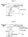
- a pressure change of the pressure intensifier cylinder (brake cylinder) 40 will be described with reference to FIGS. 5 to 8 .
- the brake control air having the BC pressure is supplied from the main air tank 21 and the supply air tank 22 which are positioned away from the bogie B2, it takes a predetermined length of time (free running time) for a brake cylinder pressure (represented by reference symbol P), which is applied to the pressure intensifier cylinder 40, to reach a specified value (lower limit value of the pressure required to generate an effective braking force: for example, 63.2% of a setting pressure P' (BC pressure) after an emergency brake operation is performed (when the emergency brake signal NA is output).
- a brake cylinder pressure represented by reference symbol P
- a brake time constant is defined to be time t1 from when the increase in the brake cylinder pressure P is started until the brake cylinder pressure P reaches the specified value
- the free running time is represented by the sum of the dead time t0 and the brake time constant t1.
- FIG. 6 shows free running distances in this case.
- Each of the free running distances is a value that is obtained by multiplying the corresponding the free running time by the corresponding speed (initial speed) of the vehicle B when an emergency brake operation is performed.
- FIG. 6 shows the free running distance for each of the initial speeds in a case where the free running time is assumed to be 1.5 seconds.
- the brake control device 10 when the brake control device 10 outputs the emergency brake control signal S3 based on the emergency brake command NA, the additional emergency brake solenoid valve 31 of the emergency pressure control device 30 is opened.
- the second compressed air having the AS pressure inside the auxiliary air tank 33 is supplied as the emergency brake air to the one inlet port of the double check valve 32 via the additional emergency brake solenoid valve 31.
- the brake control device 10 determines the set BC pressure of the brake control air which has to be supplied to the pressure intensifier cylinder 40, based on the weight of the vehicle B determined according to the AS pressure, and based on a speed signal input from the speed meter (not shown) (refer to FIG. 4 ).
- the brake control device 10 determines the set BC pressure of the brake control air as described above, the brake control device 10 controls the opening of the electro-pneumatic change valve 11 in a feedback manner such that the BC pressure of the brake control air, which is supplied from the relay valve 13 to the pressure intensifier cylinder 40, becomes the set BC pressure (a pressure within an allowable range ⁇ 20 kPa). Accordingly, the brake control air having substantially the same BC pressure as the set BC pressure is supplied from the relay valve 13 to the other inlet port of the double check valve 32. As shown in FIG. 4 , the BC pressure of the brake control air is controlled in a feedback manner, and thus, the BC pressure of the brake control air has an error of ⁇ 20 kPa with respect to the set BC pressure.
- the double check valve 32 selectively supplies one compressed air having a higher pressure among the brake control air and the emergency brake air to the pressure intensifier cylinder 40.
- the auxiliary air tanks 33 and 33', the additional emergency brake solenoid valve 31, and the double check valve 32 are connected to each other on the same bogie B2 via the pipelines 33A, 33B, and 50, and are disposed very close to each other.
- the main air tank 21, the supply air tank 22, the brake control device 10, the electro-pneumatic change valve 11, and the relay valve 13 are installed on the vehicle body B 1.
- the relay valve 13 is connected to the double check valve 32 on the bogie B2 via the pipeline 13A longer than the pipeline 50. For this reason, before the brake control air having the BC pressure reaches the pressure intensifier cylinder 40 via the double check valve 32, the emergency brake air having the AS pressure is quickly supplied to the pressure intensifier cylinder 40 via the double check valve 32.
- the emergency brake air is supplied to the pressure intensifier cylinder 40 prior to the brake control air being supplied thereto, the internal pressure of the pressure intensifier cylinder 40 starts to be quickly increased from when the emergency brake command NA is generated. For this reason, unlike the conventional vehicle brake apparatus in which the "dead time t0" occurs, the "dead time t0" does not occur in the vehicle brake apparatus 100 of the embodiment.
- the vehicle brake apparatus 100 of the embodiment since the emergency brake air is supplied to the pressure intensifier cylinder 40 prior to the brake control air being supplied thereto, the free running time from when the emergency brake command NA is generated until the internal pressure of the pressure intensifier cylinder 40 reaches the specified value (63.2% of the setting pressure P') becomes time t2 (brake time constant) that is shorter than the free running time (t0 + t1) occurring in the conventional vehicle brake apparatus.
- the vehicle brake apparatus 100 of the embodiment is capable of considerably reducing the free running distance of the vehicle B during emergency braking compared to the conventional vehicle brake apparatus (the internal pressure (AS pressure) of the pressure intensifier cylinder 40 in this case is shown by reference symbol PA in FIG. 7 ).
- the free running time becomes time t2 that is shorter than the free running time (t0 + t1) occurring in the conventional vehicle brake apparatus.
- the completely same emergency brake operation is also performed in a case where the additional emergency brake solenoid valve 31 of the emergency pressure control device 30 is opened due to the shutting off of electric power supplied from the overhead power line, instead of the emergency brake control signal S3 being output from the brake control device 10.
- auxiliary air tanks 33 and 33' are provided on the bogie B2 of the vehicle B outside of the brake operation system 1, and supply the emergency brake air having the AS pressure during an emergency brake operation before the brake control air having the BC pressure is supplied from the normal air tanks 21 and 22, it is possible to reduce the length of each of the pipelines 33A, 33B, 50, and 51 between the auxiliary air tanks 33 and 33' and the pressure intensifier cylinder 40 that is the brake cylinder A.
- the second compressed air inside the auxiliary air tanks 33 and 33' can be quickly supplied as the emergency brake air to the pressure intensifier cylinder 40 via the short pipeline such that the internal pressure of the pressure intensifier cylinder 40 can be quickly increased to the specified value during an emergency brake operation.
- the second compressed air inside the auxiliary air tanks 33 and 33' provided on the bogie B2 of the vehicle B is directly supplied to the additional emergency brake solenoid valve 31 of the emergency pressure control device 30 which is opened during an emergency brake operation, it is possible to omit the installation of an air source, a pressure regulating valve, and a control device thereof which are additionally provided in the conventional brake system. As a result, it is possible to simplify the entire configuration of the vehicle brake apparatus 100.
- the emergency pressure control device 30 since the emergency pressure control device 30 includes the double check valve 32 that selectively supplies one compressed air having a higher pressure among the brake control air and the emergency brake air to the pressure intensifier cylinder 40; and the additional emergency brake solenoid valve 31 that opens the pipeline for supplying the second compressed air inside the auxiliary air tanks 33 and 33' to the double check valve 32 during an emergency brake operation, the emergency pressure control device 30 is capable of supplying the second compressed air inside the auxiliary air tanks 33 and 33' (positioned very close to the double check valve 32) to the double check valve 32 as the emergency brake air by opening the additional emergency brake solenoid valve 31 during an emergency brake operation such as the occurrence of an earthquake.
- the emergency brake air is preferentially supplied from the auxiliary air tanks 33 and 33' to the pressure intensifier cylinder 40. Accordingly, it is possible to quickly increase the internal pressure of the pressure intensifier cylinder 40, and it is possible to effectively apply braking force to the wheels W.
- the AS pressure of the second compressed air stored in the auxiliary air tanks 33 and 33' is lower than or equal to the BC pressure of the brake control air that is supplied from the relay valve 13 to the double check valve 32, even if the second compressed air inside the auxiliary air tanks 33 and 33' is preferentially supplied as the emergency brake air to the pressure intensifier cylinder 40 during an emergency brake operation, it is possible to prevent the occurrence of trouble such as the wheels W being locked and slipping without abnormally increasing the internal pressure of the pressure intensifier cylinder 40.
- auxiliary air tanks 33 and 33' are used as the second tanks which supply the second compressed air to the air springs between the bogie B2 and the vehicle body B1
- the auxiliary air tanks 33 and 33' are used as the second tanks which are respectively provided on both right and left sides of a framework of the bogie B2 and supply the second compressed air to the air springs, the auxiliary air tanks 33 and 33' are connected to each other via the differential pressure valve 34, and the second compressed air inside the auxiliary air tanks 33 and 33' is supplied to the double check valve 32 via the pipelines 33A, 33B, and 50, it is possible to ensure a predetermined volume of the auxiliary air tanks on the framework of the bogie B2. As a result, it is possible to quickly increase the internal pressure of the pressure intensifier cylinder 40 to the specified value during an emergency brake operation.
- examples of a condition for opening the additional emergency brake solenoid valve 31 of the emergency pressure control device 30 at "the occurrence of an abnormal event” include a case in which the brake control device 10 outputs the emergency brake control signal S3 based on the emergency brake command NA occurring when a driver performs an emergency brake operation, and a case in which electric power supplied to the vehicle B is shut off.
- the additional emergency brake solenoid valve 31 of the emergency pressure control device 30 may be opened.
- the additional emergency brake solenoid valve 31 of the emergency pressure control device 30 is opened based on the emergency brake command NA.
- the additional emergency brake solenoid valve 31 is set to be closed within one to two seconds after the emergency brake command NA is output. Accordingly, sliding control of the BC pressure is not hindered.
- a high-speed railroad vehicle for the Shinkansen or the like is exemplarily shown.
- the present invention can be applied to a conventional railroad vehicle including a bolsterless bogie on which air springs are mounted.
- a vehicle brake apparatus 101 in a second embodiment of the present invention will be described with reference to FIGS. 9 to 14 .
- the same reference symbols are assigned to the same configuration elements as the vehicle brake apparatus 100 in the first embodiment, and a description thereof will not be repeated here.
- FIG. 9 is a schematic diagram showing the configuration of the vehicle brake apparatus 101 in the second embodiment.
- FIG. 10 is a view showing the piping of a bogie B2 in the second embodiment.
- reference symbol 60 represents a tread cleaning device.
- FIG. 11 is a view showing the piping of a conventional bogie as a comparative example.
- the tread cleaning device 60 shown in FIGS. 9 and 10 includes an abrasive block 61 made of resin which is provided to be capable of coming into contact with or moving away from a thread of the corresponding wheel W for a rail (not shown), and cleans the tread of the wheel W while being in contact with the tread; a tread cleaning cylinder 62 that operates the abrasive block 61; and a cleaning air control device 63 that supplies tread cleaning air which operates the tread cleaning cylinder 62.
- the cleaning air control device 63 is configured to include a tread cleaning solenoid valve 64 that is installed on the vehicle body B1; an additional cleaning solenoid valve 65 that is installed on the bogie B2; and a double check valve 66 that is installed on the bogie B2.
- the cleaning air control device 63 quickly supplies emergency cleaning air (compressed air having the AS pressure) that is auxiliary compressed air for the tread cleaning cylinder 62, prior to supplying tread cleaning air (compressed air having a TC pressure).
- the tread cleaning solenoid valve 64 takes in compressed air from a common pipe 90 between vehicles, a portion of which is used as the brake control air.
- the additional cleaning solenoid valve 65 is connected to one auxiliary air tank (in the embodiment, the auxiliary air tank 33') that is not connected to the additional emergency brake solenoid valve 31, out of the auxiliary air tanks (second tanks) 33 and 33' which supply the second compressed air to air springs (not shown) between the vehicle body B1 and the bogie B2 of the vehicle B.
- the additional cleaning solenoid valve 65 is an opening and closing valve that is opened based on an emergency brake control signal S3A from the brake control device 10.
- the additional cleaning solenoid valve 65 is a normally closed valve that maintains a closed state when energized where the vehicle B is run.
- the emergency brake control signal S3A is output from the brake control device 10
- the energization of the vehicle B is shut off during an emergency (for example, in a case where an electricity failure occurs due to an earthquake, in a case where the vehicle B is derailed, or in a case where a pantograph is deviated from an overhead power line)
- the additional cleaning solenoid valve 65 is opened.
- the AS pressure of the second compressed air inside the auxiliary air tanks 33 and 33' is lower than or equal to the TC pressure of the tread cleaning air that is supplied to the double check valve 66 via the tread cleaning solenoid valve 64.
- the double check valve 66 includes two inlet ports and one outlet port. One of the inlet ports of the double check valve 66 is connected to the additional cleaning solenoid valve 65 via a pipeline 70. The other of the inlet ports of the double check valve 66 is connected to the tread cleaning solenoid valve 64 via a pipeline 71 longer than the pipeline 70. The outlet port of the double check valve 66 is connected to the tread cleaning cylinder 62 via a pipeline 72.
- the double check valve 66 supplies one compressed air having a higher pressure among the tread cleaning air supplied from the common pipe 90 via the tread cleaning solenoid valve 64 and the emergency cleaning air supplied from the auxiliary air tank 33' via the additional cleaning solenoid valve 65, to the tread cleaning cylinder 62.
- the abrasive block 61 shown in FIG. 10 is pressed to the tread of the wheel W by the pressure of the compressed air supplied from the double check valve 66 to the tread cleaning cylinder 62. As a result, the tread of the wheel W is cleaned.
- the additional emergency brake solenoid valve 31 of the emergency pressure control device 30 connected to the auxiliary air tank 33, and the additional cleaning solenoid valve 65 of the tread cleaning device 60 connected to the auxiliary air tank 33' are opened according to the emergency brake control signal S3 (S3A and S3B) that is output from the brake control device 10 based on the emergency brake command NA.
- the emergency brake control signal S3 (S3A and S3B) is output from the brake control device 10 to the additional emergency brake solenoid valve 31 and the additional cleaning solenoid valve 65.
- the emergency brake control signal S3A is also output from the brake control device 10 to the tread cleaning solenoid valve 64. Accordingly, the additional emergency brake solenoid valve 31, the additional cleaning solenoid valve 65, and the tread cleaning solenoid valve 64 are simultaneously opened.
- the actual timing of the operation in this case is shown by arrow E1 in FIG. 12 .
- the thread cleaning air having the TC pressure is supplied from the common pipe 90 between the vehicles B to the double check valve 66 via the tread cleaning solenoid valve 64 (supplied in a range of "TCin” to "TCout"), and the second compressed air having the AS pressure is supplied as the emergency cleaning air from the auxiliary air tank 33' to the double check valve 66 via the additional cleaning solenoid valve 65 (supplied in a range below "AS2in").
- the double check valve 66 selectively supplies one compressed air having a higher pressure among the thread cleaning air and the emergency cleaning air to the tread cleaning cylinder 62.
- auxiliary air tanks 33' and the double check valve 66 are connected to each other on the same bogie B2 via the pipeline 70, and are disposed very close to each other. For this reason, before the tread cleaning air supplied via the pipeline 71 longer than the pipeline 70 reaches the double check valve 66, the emergency cleaning air supplied from the auxiliary air tank 33' is quickly supplied to the tread cleaning cylinder 62 via the pipeline 70 and the double check valve 66.
- the emergency cleaning air is supplied to the tread cleaning cylinder 62 prior to the thread cleaning air being supplied thereto, the internal pressure of the tread cleaning cylinder 62 starts to be quickly increased from when the emergency brake command NA is generated. For this reason, unlike the conventional vehicle brake apparatus in which a "dead time” occurs, a “dead time” does not occur in the vehicle brake apparatus 101 of the embodiment. Accordingly, the tread cleaning cylinder 62 is operated within a very short period of time from the starting of the emergency brake operation such that the abrasive block 61 is capable of cleaning the corresponding wheel tread. As a result, the emergency brake operation (to be described later) can be effectively performed.
- the braking of the wheels W for an emergency stop is operated simultaneously when the treads of the wheels W are cleaned.
- the actual timing of the operation in this case is shown by arrow E2 in FIG. 12 .
- the brake control device 10 outputs the emergency brake control signal S3A and the emergency brake control signal S3B based on the emergency brake command NA, the additional emergency brake solenoid valve 31 of the emergency pressure control device 30 is opened.
- the brake control air having the BC pressure is supplied from the supply air tank 22 to the double check valve 32 via the relay valve 13 (supplied in a range of "BCin” to "BCout"), and the emergency brake air having the AS pressure is supplied from the auxiliary air tank 33 to the double check valve 32 via the additional emergency brake solenoid valve 31 (supplied in a range below "AS1 in”).
- the double check valve 32 selectively supplies one compressed air having a higher pressure among the brake control air and the emergency brake air to the pressure intensifier cylinder 40.
- the auxiliary air tanks 33 and 33', the additional emergency brake solenoid valve 31, and the double check valve 32 are connected to each other on the same bogie B2 via the pipelines 33A, 33B, and 50, and are disposed very close to each other.
- the main air tank 21, the supply air tank 22, the brake control device 10, the electro-pneumatic change valve 11, and the relay valve 13 are installed on the vehicle body B 1.
- the relay valve 13 is connected to the double check valve 32 on the bogie B2 via the pipeline 13A longer than the pipeline 50. For this reason, before the brake control air having the BC pressure reaches the pressure intensifier cylinder 40 via the double check valve 32, the emergency brake air having the AS pressure is quickly supplied to the pressure intensifier cylinder 40 via the double check valve 32.
- FIG. 13 is a graph showing a relationship between the free running time of the tread cleaning cylinder 62 (the free running time of the pressing force of the abrasive block) and "a supply A/S pressure / a set TC pressure (the set TC pressure is a constant value)".
- FIG. 13 is a graph showing a relationship between the free running time of the tread cleaning cylinder 62 (the free running time of the pressing force of the abrasive block) and "a supply A/S pressure / a set TC pressure (the set TC pressure is a constant value)".
- FIG. 14 is a graph showing a relationship between the free running time of the pressure intensifier cylinder 40 (the free running time of the oil pressure of the pressure intensifier cylinder) and "the supply A/S pressure / the set BC pressure (the set BC pressure is a constant value)".
- ranges E3 and E5 are shown for a case in which the second compressed air having the AS pressure is preferentially supplied from the auxiliary air tanks 33 and 33' in "empty vehicles (represented by rectangular plots), "loaded vehicles (represented by rhomboidal plots), and “fully loaded vehicles (represent by colored circular plots), a range E4 is shown for a case in which the second compressed air having the AS pressure is not supplied (represented by a "white circular plot: ⁇ "), and a range E 6 is shown for an existing vehicle (represented by an "black circular plot: ⁇ ").
- 13 and 14 show (1) a case in which the AS pressures of the auxiliary air tank 33 and the auxiliary air tank 33' are set equal to a set value, (2) a case in which the AS pressure of the auxiliary air tank 33 is lower by 60 kPa than the set value, and the AS pressure of the auxiliary air tank 33' is higher by 60 kPa than the set value, (3) a case in which the AS pressure of the auxiliary air tank 33 is higher by 60 kPa than the set value, and the AS pressure of the auxiliary air tank 33' is lower by 60 kPa than the set value.
- the free running time is confirmed to be reduced from 0.8 seconds to 0.3 seconds at a pressure ratio (the supply AS pressure / the set TC pressure) of 0.66 or greater
- the free running time is confirmed to be reduced from 0.95 seconds to 0.2 seconds at a pressure ratio (the supply AS pressure / the set BC pressure) of 0.66 or greater.
- the pressure ratio is less than 0.66 in FIGS. 13 and 14
- the compressed air having at least 50% of the set TC pressure and 40% of the set BC pressure is preferentially supplied, and certain effects are obtained.
- the vehicle brake apparatus 101 in the second embodiment includes the tread cleaning device 60 that operates the abrasive block 61 by supplying the tread cleaning air having the TC pressure to the tread cleaning cylinder 62 which operates the abrasive block 61.
- the tread cleaning device 60 supplies the emergency cleaning air, which has a pressure (AS pressure) lower than or equal to the TC pressure of the tread cleaning air, to the tread cleaning cylinder 62 prior to supplying the tread cleaning air thereto.
- the tread cleaning cylinder 62 is operated within a very short period of time from the starting of an emergency brake operation such that the abrasive block 61 is capable of cleaning the corresponding wheel tread. As a result, the subsequent emergency brake operation can be effectively performed.
- the auxiliary air tank (second tank) 33' is used as a supply source of the emergency cleaning air which supplies the second compressed air to the air springs between the bogie B2 and the vehicle body B1, it is not necessary to provide special equipment in a conventional tread cleaning system. For this reason, the emergency cleaning air is supplied from the auxiliary air tank 33'such that the internal pressure of the tread cleaning cylinder 62 can be quickly increased to a specified value (lower limit value of the pressure required for the abrasive block 61 to effectively clean the corresponding wheel tread).
- auxiliary air tank 33' which supplies the second compressed air to the air springs between the vehicle body B1 and the bogie B2, as the supply source of the emergency cleaning air. Accordingly, the second compressed air inside the auxiliary air tank 33' is quickly supplied as the emergency cleaning air to the tread cleaning cylinder 62 via the short pipeline. As a result, it is possible to quickly increase the internal pressure of the tread cleaning cylinder 62 to the specified value.
- the vehicle brake apparatus 101 in the second embodiment adopts a configuration in which the second tanks are respectively installed on both lateral sides of the bogie B2 and are configured to include the pair of the auxiliary air tanks 33 and 33' which are connected to each other via the differential pressure valve 34, the second compressed air inside the one auxiliary air tank 33 is used as the emergency brake air, and the second compressed air inside the other auxiliary air tank 33' is used as the emergency cleaning air.
- the auxiliary air tanks 33 and 33' forming the second tanks are used as air sources, and supply emergency compressed air (emergency brake air and emergency cleaning air) to the pressure intensifier cylinder 40 and the tread cleaning cylinder 62 such that the compressed air can be quickly supplied at a set pressure.
- emergency compressed air emergency brake air and emergency cleaning air
- examples of a condition for opening the additional emergency brake solenoid valve 31 and the additional cleaning solenoid valve 65 at "the occurrence of an abnormal event” include a case in which the brake control device 10 outputs the emergency brake control signal S3 (S3A and S3B) based on the emergency brake command NA occurring when a driver performs an emergency brake operation, and a case in which electric power supplied to the vehicle B is shut off.
- the additional emergency brake solenoid valve 31 and the additional cleaning solenoid valve 65 may be opened.
- the present invention it is possible to provide a vehicle brake apparatus capable of reducing the free running time of a vehicle during emergency braking by adopting a simple configuration. That is, according to the present invention, it is possible to reduce the free running time of the vehicle during emergency braking. Accordingly, particularly, in a vehicle moving at a high speed, the aforementioned effects become a great merit in the viewpoint of improved safety. As a result, the present invention has sufficient industrial applicability.
Landscapes
- Engineering & Computer Science (AREA)
- Transportation (AREA)
- Mechanical Engineering (AREA)
- Braking Systems And Boosters (AREA)
- Valves And Accessory Devices For Braking Systems (AREA)
- Regulating Braking Force (AREA)
Applications Claiming Priority (2)
| Application Number | Priority Date | Filing Date | Title |
|---|---|---|---|
| JP2013228570A JP6195410B2 (ja) | 2013-11-01 | 2013-11-01 | 車両用ブレーキ装置 |
| PCT/JP2014/079108 WO2015064751A1 (ja) | 2013-11-01 | 2014-10-31 | 車両用ブレーキ装置 |
Publications (3)
| Publication Number | Publication Date |
|---|---|
| EP3064409A1 true EP3064409A1 (de) | 2016-09-07 |
| EP3064409A4 EP3064409A4 (de) | 2017-07-12 |
| EP3064409B1 EP3064409B1 (de) | 2018-07-11 |
Family
ID=53004346
Family Applications (1)
| Application Number | Title | Priority Date | Filing Date |
|---|---|---|---|
| EP14856882.7A Active EP3064409B1 (de) | 2013-11-01 | 2014-10-31 | Eisenbahnwaggon-bremsanlage |
Country Status (6)
| Country | Link |
|---|---|
| EP (1) | EP3064409B1 (de) |
| JP (1) | JP6195410B2 (de) |
| CN (1) | CN105705391B (de) |
| ES (1) | ES2689026T3 (de) |
| TW (1) | TWI532615B (de) |
| WO (1) | WO2015064751A1 (de) |
Cited By (2)
| Publication number | Priority date | Publication date | Assignee | Title |
|---|---|---|---|---|
| EP3330141A1 (de) * | 2016-12-02 | 2018-06-06 | Harris Corporation | Hybrides pneumatisches regeneratives system für schienenfahrzeuge |
| WO2018172120A1 (de) * | 2017-03-22 | 2018-09-27 | Knorr-Bremse Systeme für Schienenfahrzeuge GmbH | Bremsvorrichtung für schienenfahrzeuge und verfahren zum bremsen von schienenfahrzeugen |
Families Citing this family (4)
| Publication number | Priority date | Publication date | Assignee | Title |
|---|---|---|---|---|
| JP7220561B2 (ja) * | 2018-12-26 | 2023-02-10 | ナブテスコ株式会社 | 鉄道車両用空気圧縮システム |
| JP6802338B2 (ja) * | 2019-09-26 | 2020-12-16 | ナブテスコオートモーティブ株式会社 | ブレーキシステム及びブレーキシステムの制御方法 |
| KR102082378B1 (ko) * | 2019-11-14 | 2020-02-27 | 주식회사 인터라온 | 공압을 이용하여 비상제동 기능을 구현하는 전기기계식 브레이크 |
| JP7053769B2 (ja) * | 2020-11-26 | 2022-04-12 | ナブテスコオートモーティブ株式会社 | ブレーキシステム及びブレーキシステムの制御方法 |
Family Cites Families (4)
| Publication number | Priority date | Publication date | Assignee | Title |
|---|---|---|---|---|
| JPH07257339A (ja) * | 1994-03-25 | 1995-10-09 | Nissan Diesel Motor Co Ltd | 制動力制御装置 |
| JP2000177587A (ja) * | 1998-12-16 | 2000-06-27 | Railway Technical Res Inst | 車両制駆動方法及び車両制駆動装置 |
| JP2009119963A (ja) * | 2007-11-13 | 2009-06-04 | Railway Technical Res Inst | 電気鉄道車両 |
| JP5514653B2 (ja) * | 2010-07-05 | 2014-06-04 | 西日本旅客鉄道株式会社 | 新幹線車両用ブレーキシステム |
-
2013
- 2013-11-01 JP JP2013228570A patent/JP6195410B2/ja active Active
-
2014
- 2014-10-31 CN CN201480058973.9A patent/CN105705391B/zh active Active
- 2014-10-31 EP EP14856882.7A patent/EP3064409B1/de active Active
- 2014-10-31 ES ES14856882.7T patent/ES2689026T3/es active Active
- 2014-10-31 TW TW103137821A patent/TWI532615B/zh not_active IP Right Cessation
- 2014-10-31 WO PCT/JP2014/079108 patent/WO2015064751A1/ja active Application Filing
Cited By (3)
| Publication number | Priority date | Publication date | Assignee | Title |
|---|---|---|---|---|
| EP3330141A1 (de) * | 2016-12-02 | 2018-06-06 | Harris Corporation | Hybrides pneumatisches regeneratives system für schienenfahrzeuge |
| US10363946B2 (en) | 2016-12-02 | 2019-07-30 | Harris Corporation | Hybrid pneumatic regenerative system for railway vehicles |
| WO2018172120A1 (de) * | 2017-03-22 | 2018-09-27 | Knorr-Bremse Systeme für Schienenfahrzeuge GmbH | Bremsvorrichtung für schienenfahrzeuge und verfahren zum bremsen von schienenfahrzeugen |
Also Published As
| Publication number | Publication date |
|---|---|
| ES2689026T3 (es) | 2018-11-08 |
| JP2015085909A (ja) | 2015-05-07 |
| EP3064409A4 (de) | 2017-07-12 |
| TWI532615B (zh) | 2016-05-11 |
| JP6195410B2 (ja) | 2017-09-13 |
| CN105705391B (zh) | 2018-09-18 |
| CN105705391A (zh) | 2016-06-22 |
| WO2015064751A1 (ja) | 2015-05-07 |
| EP3064409B1 (de) | 2018-07-11 |
| TW201522131A (zh) | 2015-06-16 |
Similar Documents
| Publication | Publication Date | Title |
|---|---|---|
| EP3064409B1 (de) | Eisenbahnwaggon-bremsanlage | |
| JP5158253B2 (ja) | ブレーキ制御装置 | |
| TWI436916B (zh) | 氣動式緊急煞車之釋放定時器 | |
| CN109383554B (zh) | 控制车集中制动控制系统、方法及动车组制动控制系统 | |
| US8538610B2 (en) | System and method for determining whether a locomotive in a consist is in leading mode or trailing mode | |
| RU2688643C2 (ru) | Электрический стояночный тормоз для транспортного средства | |
| AU2013205185B2 (en) | Park Brake Control Assembly | |
| EP2165902B1 (de) | Schienenfahrzeug-Elektropneumatikbremssystem und Schienenfahrzeug mit diesem System | |
| CN102951173B (zh) | 一种轨道车辆制动系统紧急制动装置及其制动方法 | |
| AU2016305330B2 (en) | System for controlling a railway train for the transport of goods comprising a plurality of locomotives | |
| CN101767583A (zh) | 一种用于机车均衡风缸的压力控制装置 | |
| KR100732566B1 (ko) | 기관차의 공기제동장치 | |
| CN107218258A (zh) | 一种城市轨道交通制动系统用液压控制单元 | |
| JP7308047B2 (ja) | 鉄道車両用ブレーキ装置 | |
| KR200459344Y1 (ko) | 철도차량의 공기제동장치 | |
| KR20140006031A (ko) | 차량의 압축 공기 공급 장치용 다중 회로 보호 밸브 및 다중 회로 보호 밸브의 작동 방법 | |
| CN111976687B (zh) | 一种轨道车辆制动缸压力控制方法及系统 | |
| CN105752106A (zh) | 轨道非标车辆空气制动系统 | |
| JP2022087828A (ja) | 鉄道車両のためのブレーキ制御システム | |
| RU2509015C1 (ru) | Способ работы автоматического стояночного тормоза | |
| RU2211161C1 (ru) | Кран машиниста вспомогательного тормоза железнодорожного тягового средства | |
| KR101796672B1 (ko) | 완해 불량 방지 밸브를 포함하는 철도 차량용 제동장치 | |
| CN202320278U (zh) | 一种机车制动机缓解装置 | |
| US11904827B2 (en) | Rotational monitoring system of at least one axle for a railway vehicle or train | |
| US735544A (en) | Air-brake system. |
Legal Events
| Date | Code | Title | Description |
|---|---|---|---|
| PUAI | Public reference made under article 153(3) epc to a published international application that has entered the european phase |
Free format text: ORIGINAL CODE: 0009012 |
|
| 17P | Request for examination filed |
Effective date: 20160601 |
|
| AK | Designated contracting states |
Kind code of ref document: A1 Designated state(s): AL AT BE BG CH CY CZ DE DK EE ES FI FR GB GR HR HU IE IS IT LI LT LU LV MC MK MT NL NO PL PT RO RS SE SI SK SM TR |
|
| AX | Request for extension of the european patent |
Extension state: BA ME |
|
| DAX | Request for extension of the european patent (deleted) | ||
| A4 | Supplementary search report drawn up and despatched |
Effective date: 20170614 |
|
| RIC1 | Information provided on ipc code assigned before grant |
Ipc: B60T 17/22 20060101ALI20170608BHEP Ipc: B60T 17/00 20060101AFI20170608BHEP Ipc: B60T 13/66 20060101ALI20170608BHEP Ipc: B60T 15/36 20060101ALI20170608BHEP |
|
| RIC1 | Information provided on ipc code assigned before grant |
Ipc: B60T 13/66 20060101ALI20171130BHEP Ipc: B60T 17/00 20060101AFI20171130BHEP Ipc: B60T 15/36 20060101ALI20171130BHEP Ipc: B60T 17/22 20060101ALI20171130BHEP |
|
| GRAP | Despatch of communication of intention to grant a patent |
Free format text: ORIGINAL CODE: EPIDOSNIGR1 |
|
| INTG | Intention to grant announced |
Effective date: 20180124 |
|
| GRAS | Grant fee paid |
Free format text: ORIGINAL CODE: EPIDOSNIGR3 |
|
| GRAA | (expected) grant |
Free format text: ORIGINAL CODE: 0009210 |
|
| AK | Designated contracting states |
Kind code of ref document: B1 Designated state(s): AL AT BE BG CH CY CZ DE DK EE ES FI FR GB GR HR HU IE IS IT LI LT LU LV MC MK MT NL NO PL PT RO RS SE SI SK SM TR |
|
| REG | Reference to a national code |
Ref country code: GB Ref legal event code: FG4D |
|
| RIN1 | Information on inventor provided before grant (corrected) |
Inventor name: SAGA SHIN-ICHI Inventor name: SAWADA MASANORI Inventor name: SAKAGUCHI ATSUSHI |
|
| REG | Reference to a national code |
Ref country code: CH Ref legal event code: EP |
|
| REG | Reference to a national code |
Ref country code: AT Ref legal event code: REF Ref document number: 1016553 Country of ref document: AT Kind code of ref document: T Effective date: 20180715 |
|
| REG | Reference to a national code |
Ref country code: IE Ref legal event code: FG4D |
|
| REG | Reference to a national code |
Ref country code: DE Ref legal event code: R096 Ref document number: 602014028496 Country of ref document: DE |
|
| REG | Reference to a national code |
Ref country code: FR Ref legal event code: PLFP Year of fee payment: 5 |
|
| REG | Reference to a national code |
Ref country code: ES Ref legal event code: FG2A Ref document number: 2689026 Country of ref document: ES Kind code of ref document: T3 Effective date: 20181108 |
|
| REG | Reference to a national code |
Ref country code: NL Ref legal event code: MP Effective date: 20180711 |
|
| REG | Reference to a national code |
Ref country code: CH Ref legal event code: NV Representative=s name: E. BLUM AND CO. AG PATENT- UND MARKENANWAELTE , CH Ref country code: CH Ref legal event code: PUEA Owner name: NIPPON STEEL AND SUMITOMO METAL CORPORATION, JP Free format text: FORMER OWNER: NIPPON STEEL AND SUMITOMO METAL CORPORATION, JP |
|
| REG | Reference to a national code |
Ref country code: LT Ref legal event code: MG4D |
|
| RAP2 | Party data changed (patent owner data changed or rights of a patent transferred) |
Owner name: NIPPON STEEL & SUMITOMO METAL CORPORATION Owner name: RAILWAY TECHNICAL RESEARCH INSTITUTE |
|
| PG25 | Lapsed in a contracting state [announced via postgrant information from national office to epo] |
Ref country code: NL Free format text: LAPSE BECAUSE OF FAILURE TO SUBMIT A TRANSLATION OF THE DESCRIPTION OR TO PAY THE FEE WITHIN THE PRESCRIBED TIME-LIMIT Effective date: 20180711 |
|
| REG | Reference to a national code |
Ref country code: AT Ref legal event code: PC Ref document number: 1016553 Country of ref document: AT Kind code of ref document: T Owner name: NIPPON STEEL & SUMITOMO METAL CORPORATION, JP Effective date: 20181115 |
|
| PG25 | Lapsed in a contracting state [announced via postgrant information from national office to epo] |
Ref country code: NO Free format text: LAPSE BECAUSE OF FAILURE TO SUBMIT A TRANSLATION OF THE DESCRIPTION OR TO PAY THE FEE WITHIN THE PRESCRIBED TIME-LIMIT Effective date: 20181011 Ref country code: GR Free format text: LAPSE BECAUSE OF FAILURE TO SUBMIT A TRANSLATION OF THE DESCRIPTION OR TO PAY THE FEE WITHIN THE PRESCRIBED TIME-LIMIT Effective date: 20181012 Ref country code: FI Free format text: LAPSE BECAUSE OF FAILURE TO SUBMIT A TRANSLATION OF THE DESCRIPTION OR TO PAY THE FEE WITHIN THE PRESCRIBED TIME-LIMIT Effective date: 20180711 Ref country code: RS Free format text: LAPSE BECAUSE OF FAILURE TO SUBMIT A TRANSLATION OF THE DESCRIPTION OR TO PAY THE FEE WITHIN THE PRESCRIBED TIME-LIMIT Effective date: 20180711 Ref country code: SE Free format text: LAPSE BECAUSE OF FAILURE TO SUBMIT A TRANSLATION OF THE DESCRIPTION OR TO PAY THE FEE WITHIN THE PRESCRIBED TIME-LIMIT Effective date: 20180711 Ref country code: IS Free format text: LAPSE BECAUSE OF FAILURE TO SUBMIT A TRANSLATION OF THE DESCRIPTION OR TO PAY THE FEE WITHIN THE PRESCRIBED TIME-LIMIT Effective date: 20181111 Ref country code: PL Free format text: LAPSE BECAUSE OF FAILURE TO SUBMIT A TRANSLATION OF THE DESCRIPTION OR TO PAY THE FEE WITHIN THE PRESCRIBED TIME-LIMIT Effective date: 20180711 Ref country code: BG Free format text: LAPSE BECAUSE OF FAILURE TO SUBMIT A TRANSLATION OF THE DESCRIPTION OR TO PAY THE FEE WITHIN THE PRESCRIBED TIME-LIMIT Effective date: 20181011 Ref country code: LT Free format text: LAPSE BECAUSE OF FAILURE TO SUBMIT A TRANSLATION OF THE DESCRIPTION OR TO PAY THE FEE WITHIN THE PRESCRIBED TIME-LIMIT Effective date: 20180711 |
|
| REG | Reference to a national code |
Ref country code: GB Ref legal event code: 732E Free format text: REGISTERED BETWEEN 20190110 AND 20190116 |
|
| PG25 | Lapsed in a contracting state [announced via postgrant information from national office to epo] |
Ref country code: AL Free format text: LAPSE BECAUSE OF FAILURE TO SUBMIT A TRANSLATION OF THE DESCRIPTION OR TO PAY THE FEE WITHIN THE PRESCRIBED TIME-LIMIT Effective date: 20180711 Ref country code: LV Free format text: LAPSE BECAUSE OF FAILURE TO SUBMIT A TRANSLATION OF THE DESCRIPTION OR TO PAY THE FEE WITHIN THE PRESCRIBED TIME-LIMIT Effective date: 20180711 Ref country code: HR Free format text: LAPSE BECAUSE OF FAILURE TO SUBMIT A TRANSLATION OF THE DESCRIPTION OR TO PAY THE FEE WITHIN THE PRESCRIBED TIME-LIMIT Effective date: 20180711 |
|
| REG | Reference to a national code |
Ref country code: ES Ref legal event code: PC2A Owner name: NIPPON STEEL & SUMITOMO METAL CORPORATION Effective date: 20190329 |
|
| REG | Reference to a national code |
Ref country code: DE Ref legal event code: R097 Ref document number: 602014028496 Country of ref document: DE |
|
| PG25 | Lapsed in a contracting state [announced via postgrant information from national office to epo] |
Ref country code: RO Free format text: LAPSE BECAUSE OF FAILURE TO SUBMIT A TRANSLATION OF THE DESCRIPTION OR TO PAY THE FEE WITHIN THE PRESCRIBED TIME-LIMIT Effective date: 20180711 Ref country code: CZ Free format text: LAPSE BECAUSE OF FAILURE TO SUBMIT A TRANSLATION OF THE DESCRIPTION OR TO PAY THE FEE WITHIN THE PRESCRIBED TIME-LIMIT Effective date: 20180711 Ref country code: EE Free format text: LAPSE BECAUSE OF FAILURE TO SUBMIT A TRANSLATION OF THE DESCRIPTION OR TO PAY THE FEE WITHIN THE PRESCRIBED TIME-LIMIT Effective date: 20180711 |
|
| PLBE | No opposition filed within time limit |
Free format text: ORIGINAL CODE: 0009261 |
|
| STAA | Information on the status of an ep patent application or granted ep patent |
Free format text: STATUS: NO OPPOSITION FILED WITHIN TIME LIMIT |
|
| PG25 | Lapsed in a contracting state [announced via postgrant information from national office to epo] |
Ref country code: SM Free format text: LAPSE BECAUSE OF FAILURE TO SUBMIT A TRANSLATION OF THE DESCRIPTION OR TO PAY THE FEE WITHIN THE PRESCRIBED TIME-LIMIT Effective date: 20180711 Ref country code: SK Free format text: LAPSE BECAUSE OF FAILURE TO SUBMIT A TRANSLATION OF THE DESCRIPTION OR TO PAY THE FEE WITHIN THE PRESCRIBED TIME-LIMIT Effective date: 20180711 Ref country code: DK Free format text: LAPSE BECAUSE OF FAILURE TO SUBMIT A TRANSLATION OF THE DESCRIPTION OR TO PAY THE FEE WITHIN THE PRESCRIBED TIME-LIMIT Effective date: 20180711 |
|
| REG | Reference to a national code |
Ref country code: DE Ref legal event code: R082 Ref document number: 602014028496 Country of ref document: DE Representative=s name: VOSSIUS & PARTNER PATENTANWAELTE RECHTSANWAELT, DE Ref country code: DE Ref legal event code: R081 Ref document number: 602014028496 Country of ref document: DE Owner name: RAILWAY TECHNICAL RESEARCH INSTITUTE, KOKUBUNJ, JP Free format text: FORMER OWNERS: NIPPON STEEL & SUMITOMO METAL CORPORATION, TOKYO, JP; RAILWAY TECHNICAL RESEARCH INSTITUTE, KOKUBUNJI, TOKIO/TOKYO, JP Ref country code: DE Ref legal event code: R081 Ref document number: 602014028496 Country of ref document: DE Owner name: NIPPON STEEL CORPORATION, JP Free format text: FORMER OWNERS: NIPPON STEEL & SUMITOMO METAL CORPORATION, TOKYO, JP; RAILWAY TECHNICAL RESEARCH INSTITUTE, KOKUBUNJI, TOKIO/TOKYO, JP |
|
| 26N | No opposition filed |
Effective date: 20190412 |
|
| REG | Reference to a national code |
Ref country code: BE Ref legal event code: MM Effective date: 20181031 |
|
| PG25 | Lapsed in a contracting state [announced via postgrant information from national office to epo] |
Ref country code: MC Free format text: LAPSE BECAUSE OF FAILURE TO SUBMIT A TRANSLATION OF THE DESCRIPTION OR TO PAY THE FEE WITHIN THE PRESCRIBED TIME-LIMIT Effective date: 20180711 Ref country code: LU Free format text: LAPSE BECAUSE OF NON-PAYMENT OF DUE FEES Effective date: 20181031 |
|
| REG | Reference to a national code |
Ref country code: AT Ref legal event code: UEP Ref document number: 1016553 Country of ref document: AT Kind code of ref document: T Effective date: 20180711 |
|
| REG | Reference to a national code |
Ref country code: IE Ref legal event code: MM4A |
|
| PG25 | Lapsed in a contracting state [announced via postgrant information from national office to epo] |
Ref country code: SI Free format text: LAPSE BECAUSE OF FAILURE TO SUBMIT A TRANSLATION OF THE DESCRIPTION OR TO PAY THE FEE WITHIN THE PRESCRIBED TIME-LIMIT Effective date: 20180711 Ref country code: BE Free format text: LAPSE BECAUSE OF NON-PAYMENT OF DUE FEES Effective date: 20181031 |
|
| PG25 | Lapsed in a contracting state [announced via postgrant information from national office to epo] |
Ref country code: IE Free format text: LAPSE BECAUSE OF NON-PAYMENT OF DUE FEES Effective date: 20181031 |
|
| PG25 | Lapsed in a contracting state [announced via postgrant information from national office to epo] |
Ref country code: MT Free format text: LAPSE BECAUSE OF NON-PAYMENT OF DUE FEES Effective date: 20181031 |
|
| PG25 | Lapsed in a contracting state [announced via postgrant information from national office to epo] |
Ref country code: TR Free format text: LAPSE BECAUSE OF FAILURE TO SUBMIT A TRANSLATION OF THE DESCRIPTION OR TO PAY THE FEE WITHIN THE PRESCRIBED TIME-LIMIT Effective date: 20180711 |
|
| PG25 | Lapsed in a contracting state [announced via postgrant information from national office to epo] |
Ref country code: PT Free format text: LAPSE BECAUSE OF FAILURE TO SUBMIT A TRANSLATION OF THE DESCRIPTION OR TO PAY THE FEE WITHIN THE PRESCRIBED TIME-LIMIT Effective date: 20180711 |
|
| PG25 | Lapsed in a contracting state [announced via postgrant information from national office to epo] |
Ref country code: HU Free format text: LAPSE BECAUSE OF FAILURE TO SUBMIT A TRANSLATION OF THE DESCRIPTION OR TO PAY THE FEE WITHIN THE PRESCRIBED TIME-LIMIT; INVALID AB INITIO Effective date: 20141031 Ref country code: CY Free format text: LAPSE BECAUSE OF FAILURE TO SUBMIT A TRANSLATION OF THE DESCRIPTION OR TO PAY THE FEE WITHIN THE PRESCRIBED TIME-LIMIT Effective date: 20180711 Ref country code: MK Free format text: LAPSE BECAUSE OF NON-PAYMENT OF DUE FEES Effective date: 20180711 |
|
| PGFP | Annual fee paid to national office [announced via postgrant information from national office to epo] |
Ref country code: GB Payment date: 20231025 Year of fee payment: 10 |
|
| PGFP | Annual fee paid to national office [announced via postgrant information from national office to epo] |
Ref country code: ES Payment date: 20231108 Year of fee payment: 10 |
|
| PGFP | Annual fee paid to national office [announced via postgrant information from national office to epo] |
Ref country code: IT Payment date: 20231006 Year of fee payment: 10 Ref country code: FR Payment date: 20231009 Year of fee payment: 10 Ref country code: DE Payment date: 20231027 Year of fee payment: 10 Ref country code: CH Payment date: 20231102 Year of fee payment: 10 Ref country code: AT Payment date: 20231005 Year of fee payment: 10 |