EP3063774B1 - Accouplement d'outil de soudage pourvu d'au moins un système magnétique et à d'au moins un dispositif de court-circuitage, outil de soudage et dispositif de soudage - Google Patents
Accouplement d'outil de soudage pourvu d'au moins un système magnétique et à d'au moins un dispositif de court-circuitage, outil de soudage et dispositif de soudage Download PDFInfo
- Publication number
- EP3063774B1 EP3063774B1 EP14766697.8A EP14766697A EP3063774B1 EP 3063774 B1 EP3063774 B1 EP 3063774B1 EP 14766697 A EP14766697 A EP 14766697A EP 3063774 B1 EP3063774 B1 EP 3063774B1
- Authority
- EP
- European Patent Office
- Prior art keywords
- welding tool
- coupling
- magnet system
- magnets
- tool coupling
- Prior art date
- Legal status (The legal status is an assumption and is not a legal conclusion. Google has not performed a legal analysis and makes no representation as to the accuracy of the status listed.)
- Active
Links
- 238000003466 welding Methods 0.000 title claims description 152
- 230000008878 coupling Effects 0.000 title claims description 138
- 238000010168 coupling process Methods 0.000 title claims description 138
- 238000005859 coupling reaction Methods 0.000 title claims description 138
- 230000005291 magnetic effect Effects 0.000 title claims description 82
- 230000004907 flux Effects 0.000 claims description 23
- 239000000463 material Substances 0.000 claims description 10
- XEEYBQQBJWHFJM-UHFFFAOYSA-N Iron Chemical compound [Fe] XEEYBQQBJWHFJM-UHFFFAOYSA-N 0.000 claims description 5
- 239000012212 insulator Substances 0.000 claims description 5
- 230000005294 ferromagnetic effect Effects 0.000 claims description 3
- 230000005292 diamagnetic effect Effects 0.000 claims 1
- 230000008901 benefit Effects 0.000 description 5
- 230000008859 change Effects 0.000 description 2
- 239000002889 diamagnetic material Substances 0.000 description 2
- 239000003302 ferromagnetic material Substances 0.000 description 2
- 230000002238 attenuated effect Effects 0.000 description 1
- 230000008033 biological extinction Effects 0.000 description 1
- 230000003247 decreasing effect Effects 0.000 description 1
- 230000001419 dependent effect Effects 0.000 description 1
- 238000006073 displacement reaction Methods 0.000 description 1
- 230000000694 effects Effects 0.000 description 1
- 238000003780 insertion Methods 0.000 description 1
- 230000037431 insertion Effects 0.000 description 1
- 238000009413 insulation Methods 0.000 description 1
- 238000002955 isolation Methods 0.000 description 1
- 230000007246 mechanism Effects 0.000 description 1
- 238000000034 method Methods 0.000 description 1
- 230000008569 process Effects 0.000 description 1
- 230000006641 stabilisation Effects 0.000 description 1
- 238000011105 stabilization Methods 0.000 description 1
- 230000000087 stabilizing effect Effects 0.000 description 1
- 238000005728 strengthening Methods 0.000 description 1
- XLYOFNOQVPJJNP-UHFFFAOYSA-N water Substances O XLYOFNOQVPJJNP-UHFFFAOYSA-N 0.000 description 1
Images

Classifications
-
- B—PERFORMING OPERATIONS; TRANSPORTING
- B23—MACHINE TOOLS; METAL-WORKING NOT OTHERWISE PROVIDED FOR
- B23K—SOLDERING OR UNSOLDERING; WELDING; CLADDING OR PLATING BY SOLDERING OR WELDING; CUTTING BY APPLYING HEAT LOCALLY, e.g. FLAME CUTTING; WORKING BY LASER BEAM
- B23K37/00—Auxiliary devices or processes, not specially adapted to a procedure covered by only one of the preceding main groups
- B23K37/02—Carriages for supporting the welding or cutting element
- B23K37/0241—Attachments between the welding or cutting element and the carriage
-
- B—PERFORMING OPERATIONS; TRANSPORTING
- B23—MACHINE TOOLS; METAL-WORKING NOT OTHERWISE PROVIDED FOR
- B23K—SOLDERING OR UNSOLDERING; WELDING; CLADDING OR PLATING BY SOLDERING OR WELDING; CUTTING BY APPLYING HEAT LOCALLY, e.g. FLAME CUTTING; WORKING BY LASER BEAM
- B23K31/00—Processes relevant to this subclass, specially adapted for particular articles or purposes, but not covered by only one of the preceding main groups
- B23K31/02—Processes relevant to this subclass, specially adapted for particular articles or purposes, but not covered by only one of the preceding main groups relating to soldering or welding
-
- B—PERFORMING OPERATIONS; TRANSPORTING
- B23—MACHINE TOOLS; METAL-WORKING NOT OTHERWISE PROVIDED FOR
- B23K—SOLDERING OR UNSOLDERING; WELDING; CLADDING OR PLATING BY SOLDERING OR WELDING; CUTTING BY APPLYING HEAT LOCALLY, e.g. FLAME CUTTING; WORKING BY LASER BEAM
- B23K5/00—Gas flame welding
- B23K5/22—Auxiliary equipment, e.g. backings, guides
-
- B—PERFORMING OPERATIONS; TRANSPORTING
- B23—MACHINE TOOLS; METAL-WORKING NOT OTHERWISE PROVIDED FOR
- B23K—SOLDERING OR UNSOLDERING; WELDING; CLADDING OR PLATING BY SOLDERING OR WELDING; CUTTING BY APPLYING HEAT LOCALLY, e.g. FLAME CUTTING; WORKING BY LASER BEAM
- B23K9/00—Arc welding or cutting
- B23K9/16—Arc welding or cutting making use of shielding gas
-
- B—PERFORMING OPERATIONS; TRANSPORTING
- B23—MACHINE TOOLS; METAL-WORKING NOT OTHERWISE PROVIDED FOR
- B23K—SOLDERING OR UNSOLDERING; WELDING; CLADDING OR PLATING BY SOLDERING OR WELDING; CUTTING BY APPLYING HEAT LOCALLY, e.g. FLAME CUTTING; WORKING BY LASER BEAM
- B23K9/00—Arc welding or cutting
- B23K9/32—Accessories
- B23K9/323—Combined coupling means, e.g. gas, electricity, water or the like
-
- F—MECHANICAL ENGINEERING; LIGHTING; HEATING; WEAPONS; BLASTING
- F23—COMBUSTION APPARATUS; COMBUSTION PROCESSES
- F23D—BURNERS
- F23D14/00—Burners for combustion of a gas, e.g. of a gas stored under pressure as a liquid
- F23D14/38—Torches, e.g. for brazing or heating
- F23D14/40—Torches, e.g. for brazing or heating for welding
-
- F—MECHANICAL ENGINEERING; LIGHTING; HEATING; WEAPONS; BLASTING
- F23—COMBUSTION APPARATUS; COMBUSTION PROCESSES
- F23D—BURNERS
- F23D14/00—Burners for combustion of a gas, e.g. of a gas stored under pressure as a liquid
- F23D14/46—Details, e.g. noise reduction means
- F23D14/48—Nozzles
- F23D14/52—Nozzles for torches; for blow-pipes
-
- H—ELECTRICITY
- H01—ELECTRIC ELEMENTS
- H01B—CABLES; CONDUCTORS; INSULATORS; SELECTION OF MATERIALS FOR THEIR CONDUCTIVE, INSULATING OR DIELECTRIC PROPERTIES
- H01B9/00—Power cables
-
- H—ELECTRICITY
- H01—ELECTRIC ELEMENTS
- H01R—ELECTRICALLY-CONDUCTIVE CONNECTIONS; STRUCTURAL ASSOCIATIONS OF A PLURALITY OF MUTUALLY-INSULATED ELECTRICAL CONNECTING ELEMENTS; COUPLING DEVICES; CURRENT COLLECTORS
- H01R13/00—Details of coupling devices of the kinds covered by groups H01R12/70 or H01R24/00 - H01R33/00
- H01R13/62—Means for facilitating engagement or disengagement of coupling parts or for holding them in engagement
Definitions
- the invention relates to a welding tool coupling, in particular a hose package interface or a welding torch grip piece, for connecting a welding tool, in particular a welding torch neck, to a supply line of a welding device, wherein the welding tool coupling for releasably coupling the welding tool has a coupling device by means of which a magnetic holding force is switched on and off can (claim 1; see, for example DE 200 18 124 U1 ).
- the invention further relates to a welding tool for coupling to such a welding tool coupling (see claim 20; JP 2004/167583 A ), as well as a welding device with such a welding tool coupling (see claim 24).
- a magnetic welding tool couplings of the aforementioned type is for example from the DE 200 18 124 U1 known, which describes a magnetic tool change system of a robot arm for various tools, including welding tools.
- the tool change system has at least two coupling halves, which can be detachably connected to each other via a parting plane, one coupling half being associated with the movable robot arm and the other coupling half with the welding tool.
- the welding tool is connected to the robot arm via a magnetic holding mechanism which is based on one coupling half having a ferromagnetic material and the other coupling half having a stationary permanent and / or electromagnetic system from which the corresponding ferromagnetic coupling half is magnetically attracted.
- the holding force can also be switched on and off, wherein in the case of a combined permanent-electro-magnet system of Electromagnet in the closed position, the holding force of the permanent magnet amplified and attenuated in the off position by appropriate polarity reversal or fully compensated.
- a switchable solenoid is required in any case, for which a technically complex electrical switching device must be present.
- a magnetic clamping plate on which a workpiece to be machined is magnetically fixed. The workpiece is then removable again from the clamping plate when the magnetic holding force is released.
- the clamping plate has magnets, which are each rotatably supported in a receptacle. The magnetic holding force on a workpiece can be activated or deactivated by rotating the magnets.
- Object of the present invention is to improve a welding tool coupling, a welding tool and a welding device of the type mentioned in that the welding tool can be technically as simple as possible, especially without involving an electrical switching device and preferably only one operator, connected to the welding tool coupling.
- the welding tool coupling according to the invention with a magnetic holding force which can be switched on and off is characterized in that the coupling device has at least one magnet system and at least one short-circuiting device which are displaceable relative to each other between a closed position and an open position such that the magnetic flux generated by the magnet system is in the closed position emerges from the coupling device generating the magnetic holding force and is at least partially short-circuited in the coupling device in the off position by means of the short-circuiting means with the magnetic holding force extinguished.
- the switching on and off of the magnetic holding force can be realized by a purely mechanical displacement movement of a magnet system relative to a short-circuit device, without relying on a special electrical switching device for on and Turning off an electromagnet must be resorted to.
- the solution according to the invention is based solely on the fact that the magnetic fluxes generated permanently by the first magnet system are led out of the coupling device in the closed position by the short-circuiting device and are at least partially short-circuited in the coupling device in the switch-off position.
- the short-circuiting device may comprise at least one further magnet system and / or at least one pole piece with the aid of which the magnetic holding force can be switched on and off. If the short-circuit device has at least one further magnet system-referred to below as the second magnet system-it is advantageously provided that the second magnet system in the closed position amplifies the magnetic flux generated by the first magnet system, in particular outside the coupling device, and shorts in the off position, and / or at least partially counter-compensated, so that the magnetic holding force can be switched on and off only by a purely mechanical movement of the two magnetic systems relative to each other.
- the pole piece can either serve for short-circuiting or leading out the flux generated by the first magnet system.
- the pole piece according to a further advantageous embodiment of the invention similar to the operating principle of a mechanical magnetic clamping plate or a mechanical magnetic chuck, at least two mutually magnetically isolated sections, which consist of a magnetically conductive, in particular ferromagnetic, material and are displaced relative to the first magnet system can, in such a way that the magnetic flux of the first magnet system are short-circuited via the magnetically conductive portions either within the coupling device or led out to the outside.
- the coupling device comprises a combination of a magnet system and a pole piece. It is particularly advantageous if the second magnet system is designed and arranged such that the magnetic flux generated by the totality of all magnetic systems in the closed position on the pole piece from the coupling device emerges or is led out, whereby a total of advantageously the strength of magnetic holding force is increased.
- the second magnet system a plurality of alternately poled and / or magnetically isolated from each other magnets, in particular dipole magnets having.
- the first and the second magnet system are arranged to each other such that the poles of the magnets of the first magnet system in the closed position adjacent to each of the same name and in the off position at each unlike poles of the magnets of the second magnet system.
- the magnetic flux generated by the totality of the magnet systems emerges from the coupling device to generate the magnetic holding force and is at least partially short-circuited in the coupling device when the magnetic holding force is extinguished or the magnetic fluxes of the compensate at least partially for two magnet systems in the off position.
- the magnets of the first and / or the second magnet system as permanent magnets and / or be designed as electromagnets.
- Permanent magnets offer the advantage that it is possible to completely dispense with a power supply, which reduces the cost of the welding tool coupling.
- permanent magnets offer the advantage that the welding tool is still securely held in the welding tool coupling even in the event of a power failure.
- electromagnets offer the advantage that the magnetic holding force can be varied by increasing or decreasing the magnetic field exciting current flow.
- a particularly simple operation of the welding tool coupling can be achieved in that the coupling device is designed in the manner of a rotary coupling.
- the first magnet system is disposed on a particular annular switching element of preferably non-magnetizable material which is displaceable relative to the short-circuiting device, in particular rotatable about the longitudinal axis of the welding tool coupling, is mounted.
- the short-circuiting device is arranged on a particular annular switching element of preferably non-magnetizable material, which is displaceable relative to the first magnet system, in particular rotatably mounted about the longitudinal axis of the welding tool coupling.
- the coupling device when the coupling device is designed as a rotary coupling, it proves to be advantageous to arrange the magnets of the first magnet system about a longitudinal axis of the welding tool coupling.
- the magnets of the second magnet system are arranged next to each other in an annular manner, preferably also about the longitudinal axis of the welding tool coupling, wherein the pole axes of the magnets are aligned either parallel to the ring plane or perpendicular to the circumferential direction of the annular arrangement.
- the magnetic flux of the second magnet system on the one hand in the on position contributes to the magnetic holding force and on the other hand in the off position at least partially counter-compensates the magnetic flux of the first magnet system
- the magnetically insulated portions of the pole shoe are ring-segment-shaped and / or form a circular collar, preferably coaxially aligned with the longitudinal axis, at one end face in the closed position, the welding tool to be connected is held and / or adjacent to the other end side of the first magnet system.
- the pole piece has a hollow cylindrical extension, which extends to the magnetically isolated sections or the Bund of the pole piece, preferably coaxial with the longitudinal axis, connects to the interior of the welding tool coupling.
- pole piece or the individual In particular alternately poled magnets of the first and / or second magnet system, these are magnetically separated or isolated from one another magnetically by magnetic insulators of non-magnetizable, preferably diamagnetic material.
- the coupling device has both a pole piece and a second magnet system
- one magnet each of the second magnet system is arranged between two adjacent sections of the pole piece, preferably in the region of the front side of the collar adjacent to the first magnet system ,
- a switching on and off of the magnetic holding force can be ensured in a particularly effective manner.
- the magnetic flux of the first magnet system is almost completely short-circuited in the coupling device by this arrangement of the magnets of the second magnet system and the portions of the pole piece.
- each a portion of the pole piece adjacent to a respective magnet of the first magnet system wherein preferably the sections at least in the adjacent region the magnets of the first magnet system have a greater lateral extent than the magnets themselves.
- a preferably annular soft iron element may be provided, which magnetically conductively interconnects the alternating poles of the magnets of the first magnet system on one side of the first magnet system, preferably on the side facing away from the pole shoe or the collar ,
- the welding tool coupling can have at least one centering opening, preferably coaxial with its longitudinal axis, which can be brought into engagement with a corresponding centering extension on the welding tool.
- the welding tool coupling to have at least one media connection, preferably in the bottom of the centering opening, which is operatively connected to the welding tool coupling with at least one corresponding media connection on the welding tool, preferably at the end of the centering extension.
- the media are in particular electrical power, gas and / or water into consideration, which should be available during the welding process in the welding train.
- a first independent idea of the invention relates to a welding tool, in particular a welding torch neck, for coupling to the above-described welding tool coupling according to the invention.
- the contact element is annular.
- the welding tool can, as described above, have a centering extension which can be brought into engagement with the corresponding centering opening in the welding tool coupling.
- the welding tool preferably in the centering extension, advantageously has at least one media connection which can be operatively connected to the at least one media connection when the welding tool is connected to the welding tool coupling in the welding tool coupling.
- Another independent idea of the invention relates to a welding device, in particular a welding torch, with a welding tool coupling according to the invention and / or with a welding tool according to the invention of the type described above.
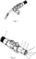
- the Fig. 1 shows a possible embodiment of a welding device according to the invention, in this case a welding torch having a welding tool coupling 1, with the aid of a welding tool 3, in this case a welding torch neck, is connected to a supply line 6 of the welding device, wherein the connection of the welding tool 3 to the welding tool coupling 1 via a Coupling device 2 takes place, which generates for releasable coupling of the welding tool 3 a switched on and off magnetic holding force.
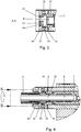
- the coupling device 2 comprises at least one magnet system 10 and at least one short-circuit device 100 which are displaceable relative to each other between a closed position and an open position such that the magnetic flux generated by the magnet system 10 in the closed position to generate the magnetic Holding force from the coupling device 2 emerges and in the off position by means of the short-circuiting device 100 to extinguish the magnetic holding force is at least partially shorted in the coupling device 2.
- the short-circuiting device 100 in addition to the first magnet system 10, a further magnet system 20, hereinafter referred to as the second magnet system 20, and a pole piece 30 on.
- the pole piece 30 has a plurality of magnetically isolated portions 31 of each other, which consist of a magnetically conductive, present ferromagnetic material.
- the magnetic insulation of the individual sections 31 of the pole piece 30 is effected by magnetic insulators 35, which consist of a non-magnetizable, present diamagnetic material.
- both the first and the second magnet system each have a plurality of alternately poled and magnetically isolated from each other dipole permanent magnets 11, 12, 21, 22, wherein in the present embodiment, both the magnets 11, 12 of the first magnet system 10 as Also, the magnets 21, 22 of the second magnet system 20 are arranged annularly next to each other about the longitudinal axis AA of the welding tool coupling.
- the polar axes of the magnets 11, 12 of the first magnet system are aligned in the direction perpendicular to the ring plane, ie parallel to the longitudinal axis AA
- the polar axes of the magnets 21, 22 of the second magnet system have an orientation parallel to the ring plane, ie perpendicular to the longitudinal axis AA of the welding tool coupling 1 on.
- FIGS. 5 and 6 show - the first and the second magnetic system 10, 20 arranged to each other such that the poles of the magnets 11, 12 of the first magnet system 10 in the closed position to each eponymous and in the off position to each unlike poles of the magnets 21, 22 of the second magnet system 20th adjoin.
- This ensures that the second magnet system 20 from the first magnet system 10th generated magnetic flux amplified in the closed position outside of the coupling device 2 and shorts in the off position or at least partially counter-compensated.
- the task of the pole piece 30 is to allow the magnetic flux generated by the totality of all the magnet systems 10, 20 to emerge from the coupling device 2 in the closed position.
- the first magnet system 10 is disposed on an annular switching element 13 of non-magnetizable material, which is rotatably mounted relative to the short-circuit device 100 about the longitudinal axis AA of the welding tool coupling 1.
- Corresponding to the pole piece is also annular or cylindrical symmetry. Accordingly, the magnetically insulated portions 31 of the pole piece 30 are formed annular segment-shaped and form a circular, coaxial with the longitudinal axis AA aligned collar 32, on one end face 33 to be connected welding tool 3 is held in the closed position and on the other end face 34, the first magnet system 10 adjacent ,
- the pole piece 30 has a hollow cylindrical extension 37, which connects to the magnetically insulated portions 31 and the collar 32 coaxial with the longitudinal axis A-A inside the welding tool coupling 1.
- each magnet 21, 22 of the second magnet system 20 is arranged between adjacent sections 31 of the pole piece 30 in the region of the front side 34 of the collar 32 adjoining the first magnet system 10.
- the switching on and off of the magnetic holding force takes place in that the switching element 13, in which the first magnet system 10 is arranged, is rotated relative to the short-circuiting device 100 by an angle corresponding to the angular distance between two adjacent, oppositely poled magnets 21, 22 of the second magnet system 20 corresponds.
- Fig. 5 the position of the coupling device 100 in the closed position
- Fig. 6 the coupling device 100 is shown in the off position.
- the magnetic flux generated by the first magnet system 10 is amplified by the second magnet system 20 and led out via the pole piece 30 or its sections 31 from the coupling device 2 via the end face 33 and into the annular, made of magnetizable material and on the End 33 adjacent contact element 40 of the welding tool 3 is guided, which is held in the result, the welding tool 3 to be connected in the closed position on the welding tool coupling 1 magenta.
- the magnetic flux generated by the first magnet system 10 is at least partially short-circuited or counter-compensated in the coupling device 2 by the changed pole arrangement of the second magnet system 20 relative to the first magnet system 10, since in this position the poles of the magnets 11, 12 of the first magnet system 10 to each opposite poles of the magnets 21, 22 of the second magnet system adjacent.
- annular soft iron element 14 is provided, which connects the alternating poles of the magnets 11, 12 magnetically conductive on the side remote in the pole piece 30 and the collar 32 side.
- a coaxial with the longitudinal axis AA extending centering opening 4 is provided, which is engageable with a corresponding centering attachment 5 on the welding tool 3 in engagement.
- a media connection 7 is provided, which is operatively connected to the welding tool 1 with a corresponding media connection 8 at the end of the centering attachment 5 of the welding tool 3 when connecting the welding tool 3.
- a media line furthermore extends through the welding tool 3 as far as the tip of the tool.
Landscapes
- Engineering & Computer Science (AREA)
- Mechanical Engineering (AREA)
- Physics & Mathematics (AREA)
- Combustion & Propulsion (AREA)
- General Engineering & Computer Science (AREA)
- Plasma & Fusion (AREA)
- Chemical & Material Sciences (AREA)
- Optics & Photonics (AREA)
- Manufacturing Of Electrical Connectors (AREA)
- Arc Welding In General (AREA)
- Resistance Welding (AREA)
- Butt Welding And Welding Of Specific Article (AREA)
- Connections Effected By Soldering, Adhesion, Or Permanent Deformation (AREA)
- Load-Engaging Elements For Cranes (AREA)
- Arc Welding Control (AREA)
- Dynamo-Electric Clutches, Dynamo-Electric Brakes (AREA)
Claims (24)
- Accouplement d'outil de soudage (1), en particulier une interface d'ensemble de tuyaux flexibles ou une poignée de chalumeau de soudage, destiné à relier un outil de soudage (3), en particulier un col de chalumeau de soudage, à une conduite d'alimentation (6) d'un dispositif de soudage, pourvu d'un dispositif d'accouplement (2) permettant l'accouplement libérable de l'outil de soudage (3) au moyen d'une force de retenue magnétique pouvant être activée et désactivée,
caractérisé en ce que le dispositif d'accouplement (2) comporte au moins un système magnétique (10) et au moins un dispositif de court-circuitage (100), lesquels peuvent être déplacés l'un par rapport à l'autre entre une position activée et une position désactivée, de telle manière que, dans la position activée, le flux magnétique généré par le système magnétique (10), en entraînant la production de la force de retenue magnétique, quitte le dispositif d'accouplement (2) et que, dans la position désactivée, il est court-circuité au moins en partie dans le dispositif d'accouplement (2) au moyen du dispositif de court-circuitage (100), en interrompant la force de retenue magnétique, en ce que le système magnétique (10) comporte respectivement plusieurs aimants (11, 12 ; 21, 22) polarisés de manière alternée et/ou magnétiquement isolés les uns de autres, en particulier des aimants dipolaires, en ce que les aimants (11, 12) du premier système magnétique (10) sont disposés côte à côte de manière annulaire et les axes polaires des aimants (11, 12) sont orientés dans la direction circonférentielle de l'agencement annulaire ou perpendiculairement au plan de l'anneau. - Accouplement d'outil de soudage (1) selon la revendication 1, caractérisé en ce que le dispositif de court-circuitage (100) comporte au moins un autre système magnétique (20) et/ou au moins une pièce polaire (30).
- Accouplement d'outil de soudage (1) selon la revendication 2, caractérisé en ce que la pièce polaire (30) comporte au moins deux sections (31) magnétiquement isolées l'une de l'autre, qui sont constituées d'un matériau magnétiquement conducteur, notamment ferromagnétique.
- Accouplement d'outil de soudage (1) selon la revendication 2 ou 3, caractérisé en ce que l'autre, le deuxième système magnétique (20) amplifie le flux magnétique généré par le premier système magnétique (10), dans la position activée, en particulier à l'extérieur du dispositif d'accouplement (2), et le court-circuite et/ou le compense au moins en partie dans la position désactivée.
- Accouplement d'outil de soudage (1) selon les revendications 2 à 4, caractérisé en ce que, dans la position activée, le flux magnétique généré par tous les systèmes magnétiques (10, 20) quitte le dispositif d'accouplement (2) par l'intermédiaire de la pièce polaire (30).
- Accouplement d'outil de soudage (1) selon l'une quelconque des revendications 2 à 5, caractérisé en ce que le second système magnétique (10 ; 20) comporte plusieurs aimants (11, 12 ; 21, 22) polarisés de manière alternée et/ou magnétiquement isolés les uns des autres, notamment des aimants dipolaires.
- Accouplement d'outil de soudage (1) selon la revendication 6, caractérisé en ce que les aimants (11, 12 ; 21, 22) du premier et/ou du second système magnétique (10 ; 20) sont réalisés sous la forme d'aimants permanents et/ou d'électroaimants.
- Accouplement d'outil de soudage (1) selon la revendication 6 ou 7, caractérisé en ce que les premier et second systèmes magnétiques (10 ; 20) sont disposés l'un par rapport à l'autre de manière à ce que, dans la position activée, les pôles des aimants (11, 12) du premier système magnétique (10) soient adjacents à des pôles respectivement identiques des aimants (21, 22) du second système magnétique (20) et, dans la position désactivés, ils soient adjacents à des pôles respectivement opposés de ces aimants.
- Accouplement d'outil de soudage (1) selon l'une quelconque des revendications 6 à 8, caractérisé en ce quea) les aimants (11, 12) du premier système magnétique (10) sont disposés autour d'un axe longitudinal (A-A) de l'accouplement d'outil de soudage (1), et/ou en ce queb) les aimants (21, 22) du second système magnétique (20) sont disposés côte à côte de manière annulaire, de préférence autour de l'axe longitudinal (A-A) de l'accouplement d'outil de soudage (1), dans lequel les axes polaires des aimants (21, 22) sont orientés parallèlement au plan de l'anneau ou perpendiculairement à la direction circonférentielle de l'agencement annulaire.
- Accouplement d'outil de soudage (1) selon l'une quelconque des revendications 2 à 9, caractérisé en ce que le/les axe(s) polaire(s) du premier système magnétique (10) est/sont orienté(s) perpendiculairement à l'axe/aux axes polaire(s) du second système magnétique (20).
- Accouplement d'outil de soudage (1) selon l'une quelconque des revendications précédentes, caractérisé en ce quea) le premier système magnétique (10) est disposé sur un élément de commutation (13), notamment annulaire, constitué de matériau de préférence non magnétisable qui est monté de manière à pouvoir être déplacé par rapport au dispositif de court-circuitage (100), en particulier de manière à ce qu'il puisse tourner autour de l'axe longitudinal (A-A) de l'accouplement d'outil de soudage (1), ou en ce queb) le dispositif de court-circuitage (100) est disposé sur un élément de commutation (13), notamment annulaire, constitué de matériau de préférence non magnétisable qui est monté de manière à pouvoir être déplacé par rapport au premier système magnétique (10), en particulier de manière à ce qu'il puisse tourner autour de l'axe longitudinal (A-A) de l'accouplement d'outil de soudage (1).
- Accouplement d'outil de soudage (1) selon l'une quelconque des revendications 3 à 11, caractérisé en ce que les sections magnétiquement isolées (31) de la pièce polaire (30) sont réalisées de manière à présenter la forme de segments annulaires et/ou forment une collerette circulaire (32), de préférence orientée coaxialement par rapport à l'axe longitudinal (A-A), sur la face avant (33) de laquelle est maintenu l'outil de soudage (3) devant être raccordé, dans la position activée, et/ou à l'autre face avant (34) de laquelle est adjacent le premier système d'aimant (10).
- Accouplement d'outil de soudage (1) selon la revendication 12, caractérisé en ce que la pièce polaire (30) présente un prolongement (37) qui se raccorde aux sections magnétiquement isolées (31) ou à la collerette (32), de préférence coaxialement par rapport à l'axe longitudinal (A-A), à l'intérieur de l'outil de soudage (1).
- Accouplement d'outil de soudage (1) selon l'une quelconque des revendications précédentes, caractérisé en ce que les sections (31) de la pièce polaire (30) et/ou les aimants (11, 12) du premier système magnétique (10) sont magnétiquement isolés les uns des autres par des isolants magnétiques (35, 36) constitués de matériau non magnétisable, de préférence diamagnétique.
- Accouplement d'outil de soudage (1) selon l'une quelconque des revendications 3 à 14, caractérisé en ce qu'un aimant respectif (21, 22) du second système magnétique (20) est disposé entre deux sections voisines (31) de la pièce polaire (30), de préférence dans la région de la face avant (34) de la collerette (32) qui est adjacente au premier système magnétique (10).
- Accouplement d'outil de soudage (1) selon l'une quelconque des revendications 3 à 15, caractérisé en ce qu'au moins dans la position activée, une section respective (31) de la pièce polaire (30) est contigüe à un aimant respectif (11, 12) du premier système magnétique (10), dans lequel les sections (31) présentent, au moins dans la région de contiguïté par rapport aux aimants (11,12) du premier système magnétique (10), une extension latérale supérieure à celle des aimants (11, 12).
- Accouplement d'outil de soudage (1) selon l'une quelconque des revendications 6 à 16, caractérisé en ce qu'il est prévu un élément de fer à souder (14) de préférence annulaire qui, d'un côté du premier système magnétique (10), de préférence sur la pièce polaire (30) ou du côté tourné à l'opposé de la collerette (32), relie l'un à l'autre de manière magnétiquement conductrice les pôles alternés des aimants (11, 12).
- Accouplement d'outil de soudage (1) selon l'une quelconque des revendications précédentes, caractérisé en ce qu'il est prévu au moins une ouverture de centrage (4), de préférence coaxiale par rapport à l'axe longitudinal(A-A), qui peut être mise en prise avec un prolongement de centrage (5) correspondant sur l'outil de soudage (3).
- Accouplement d'outil de soudage (1) selon l'une quelconque des revendications précédentes, caractérisé en ce qu'il est prévu au moins un raccord de fluide (7), de préférence au fond de l'ouverture de centrage (4), qui peut être relié de manière à coopérer, lors du raccordement de l'outil de soudage (3) à l'accouplement d'outil de soudage (1), avec au moins un raccord de fluide (8) correspondant sur l'outil de soudage (3), de préférence à l'extrémité du prolongement de centrage (5).
- Outil de soudage (3), en particulier un col de cygne, destiné à être accouplé à un accouplement d'outil de soudage (1) selon l'une quelconque des revendications précédentes, caractérisé en ce qu'il est prévu un élément de contact (40) constitué de matériau magnétisable destiné à effectuer un raccordement magnétique au dispositif d'accouplement, afin que l'outil de soudage (3), dans la position d'activation, soit attiré vers l'accouplement d'outil de soudage (1) du fait de la force de maintien magnétique.
- Outil de soudage (3) selon la revendication 20, caractérisé en ce que, pour le raccordement magnétique au dispositif d'accouplement (2), de préférence à la pièce polaire (30), en particulier à la face avant (33) de la collerette (32), l'élément de contact (40) est réalisé de manière à présenter une forme annulaire.
- Outil de soudage (3) selon la revendication 20 ou 21, caractérisé en ce qu'il est prévu un prolongement de centrage (5) qui peut être mis en prise avec l'ouverture de centrage (4) correspondante dans l'accouplement d'outil de soudage (1).
- Outil de soudage (3) selon l'une quelconque des revendications 20 à 22, caractérisé en ce qu'il est prévu au moins un raccord de fluide (8), de préférence dans le prolongement de centrage (5), qui peut être relié en liaison active, dans l'accouplement d'outil de soudage (1), avec l'au moins un raccord de fluide (7) lors du raccordement de l'outil de soudage (3) avec l'accouplement d'outil de soudage (1).
- Dispositif de soudage, en particulier un chalumeau, comportant un accouplement d'outil de soudage (1) selon l'une quelconque des revendications 1 à 19 et/ou un outil d'usinage (3) selon l'une quelconque des revendications 20 à 23.
Priority Applications (1)
| Application Number | Priority Date | Filing Date | Title |
|---|---|---|---|
| PL14766697T PL3063774T3 (pl) | 2013-10-30 | 2014-09-15 | Łącznik narzędzia spawalniczego z co najmniej jednym układem magnesu oraz co najmniej jednym mechanizmem zwierającym, narzędzie spawalnicze oraz urządzenie spawalnicze |
Applications Claiming Priority (2)
| Application Number | Priority Date | Filing Date | Title |
|---|---|---|---|
| DE102013111938.7A DE102013111938B3 (de) | 2013-10-30 | 2013-10-30 | Magnetische Schweißwerkzeugkupplung, Schweißwerkzeug sowie Schweißvorrichtung |
| PCT/EP2014/069594 WO2015062775A1 (fr) | 2013-10-30 | 2014-09-15 | Accouplement d'outil de soudage pourvu d'au moins un système magnétique et à d'au moins un dispositif de court-circuitage, outil de soudage et dispositif de soudage |
Publications (2)
| Publication Number | Publication Date |
|---|---|
| EP3063774A1 EP3063774A1 (fr) | 2016-09-07 |
| EP3063774B1 true EP3063774B1 (fr) | 2018-01-31 |
Family
ID=51564643
Family Applications (1)
| Application Number | Title | Priority Date | Filing Date |
|---|---|---|---|
| EP14766697.8A Active EP3063774B1 (fr) | 2013-10-30 | 2014-09-15 | Accouplement d'outil de soudage pourvu d'au moins un système magnétique et à d'au moins un dispositif de court-circuitage, outil de soudage et dispositif de soudage |
Country Status (12)
| Country | Link |
|---|---|
| US (1) | US9987711B2 (fr) |
| EP (1) | EP3063774B1 (fr) |
| JP (1) | JP6590816B2 (fr) |
| KR (1) | KR102182366B1 (fr) |
| CN (1) | CN105684102B (fr) |
| AU (1) | AU2014344126B2 (fr) |
| BR (1) | BR112016009323B1 (fr) |
| DE (1) | DE102013111938B3 (fr) |
| ES (1) | ES2663618T3 (fr) |
| PL (1) | PL3063774T3 (fr) |
| RU (1) | RU2662235C2 (fr) |
| WO (1) | WO2015062775A1 (fr) |
Families Citing this family (12)
| Publication number | Priority date | Publication date | Assignee | Title |
|---|---|---|---|---|
| US11845180B2 (en) * | 2015-02-20 | 2023-12-19 | Zebra Technologies Corporation | Wireless quick change end effector system for use with a robot |
| US10688669B2 (en) * | 2015-10-30 | 2020-06-23 | Fetch Robotics, Inc. | Wireless quick change end effector system for use with a robot |
| US10414055B2 (en) * | 2016-02-08 | 2019-09-17 | The Boeing Company | Robotic end effector quick change mechanism with switchable magnetic coupler with moment support |
| US10335958B2 (en) | 2016-02-08 | 2019-07-02 | The Boeing Company | Robotic end effector quick change mechanism with switchable magnetic coupler |
| US10903030B2 (en) | 2017-04-27 | 2021-01-26 | Magswitch Technology Worldwide Pty Ltd. | Variable field magnetic couplers and methods for engaging a ferromagnetic workpiece |
| CN115256001A (zh) | 2017-04-27 | 2022-11-01 | 磁转换技术全球私人有限公司 | 具有至少一个传感器布置和消磁能力的磁耦合装置 |
| KR102313077B1 (ko) | 2017-06-08 | 2021-10-14 | 마그스위치 테크놀러지 월드 와이드 피티와이 리미티드 | 전자석 전환 가능 영구 자석 디바이스 |
| CN108480872B (zh) * | 2018-03-23 | 2024-02-02 | 上海拓直数字科技有限公司 | 一种被磁化钢板的焊接方法 |
| US11230441B2 (en) * | 2018-07-16 | 2022-01-25 | XYZ Robotics Global Inc. | Robotic system for picking, sorting, and placing a plurality of random and novel objects |
| CN109253324B (zh) * | 2018-08-09 | 2020-12-22 | 长沙格力暖通制冷设备有限公司 | 一种充气嘴与管接头之间的连接结构及焊接装置 |
| CN113948908B (zh) * | 2021-10-21 | 2024-04-26 | 海固科技(苏州)有限公司 | 一种磁性锁定结构连接器 |
| KR102504775B1 (ko) * | 2022-09-20 | 2023-02-28 | 주식회사 동인산업 | 자동 용접기의 토치 |
Family Cites Families (15)
| Publication number | Priority date | Publication date | Assignee | Title |
|---|---|---|---|---|
| US2209558A (en) * | 1937-04-22 | 1940-07-30 | Karl Otto Goettsch | Magnetic clamping appliance |
| US2972485A (en) * | 1958-12-03 | 1961-02-21 | Gen Motors Corp | Magnetic chuck |
| US3181895A (en) * | 1960-09-27 | 1965-05-04 | Crawford Fitting Co | Quick-connect magnetic couplings |
| US3610875A (en) | 1970-02-11 | 1971-10-05 | Unitec Corp | Apparatus for conducting gas and electrical current |
| JPS5913945B2 (ja) * | 1979-10-12 | 1984-04-02 | 松下電器産業株式会社 | 溶接用ト−チ |
| DE3319466C1 (de) * | 1983-05-28 | 1984-03-01 | C. Reichert Optische Werke AG, 1170 Wien | Magnetische Kupplung fuer Teile eines optischen Geraets |
| JPS59224227A (ja) * | 1983-05-30 | 1984-12-17 | Fuji Jikou Kk | 永久磁石チヤツク |
| JP3610906B2 (ja) * | 1999-02-05 | 2005-01-19 | セイコーエプソン株式会社 | 磁気回路構造、これを用いた発電装置、モータ、及び電子機器 |
| US6603221B1 (en) * | 1999-04-22 | 2003-08-05 | Zhongdu Liu | Solid state electrical switch |
| JP2001071165A (ja) | 1999-09-02 | 2001-03-21 | Toyota Auto Body Co Ltd | レーザトーチの取り付け構造 |
| DE20018124U1 (de) * | 2000-10-23 | 2002-03-07 | Staeubli Vertriebs Gmbh | Werkzeugwechselsystem und Kupplungssystem |
| JP2004167583A (ja) | 2002-11-22 | 2004-06-17 | Mizuho Sangyo Kk | 溶接トーチ |
| AT507228B1 (de) * | 2008-07-30 | 2010-08-15 | Fronius Int Gmbh | Verfahren und vorrichtung zur formung des schweissdrahtendes |
| DE102009028745A1 (de) * | 2009-08-20 | 2011-02-24 | Robert Bosch Gmbh | Entkopplung eines Antriebsmotors |
| AT509982B1 (de) | 2010-08-09 | 2012-01-15 | Fronius Int Gmbh | Befestigungssystem eines brennerkörpers eines wig-schweissbrenners, brennerkörper und wig-schweissbrenner |
-
2013
- 2013-10-30 DE DE102013111938.7A patent/DE102013111938B3/de active Active
-
2014
- 2014-09-15 CN CN201480059963.7A patent/CN105684102B/zh not_active Expired - Fee Related
- 2014-09-15 ES ES14766697.8T patent/ES2663618T3/es active Active
- 2014-09-15 KR KR1020167011395A patent/KR102182366B1/ko active IP Right Grant
- 2014-09-15 WO PCT/EP2014/069594 patent/WO2015062775A1/fr active Application Filing
- 2014-09-15 US US15/030,610 patent/US9987711B2/en active Active
- 2014-09-15 AU AU2014344126A patent/AU2014344126B2/en not_active Ceased
- 2014-09-15 JP JP2016550957A patent/JP6590816B2/ja not_active Expired - Fee Related
- 2014-09-15 RU RU2016115349A patent/RU2662235C2/ru active
- 2014-09-15 BR BR112016009323-2A patent/BR112016009323B1/pt not_active IP Right Cessation
- 2014-09-15 EP EP14766697.8A patent/EP3063774B1/fr active Active
- 2014-09-15 PL PL14766697T patent/PL3063774T3/pl unknown
Also Published As
| Publication number | Publication date |
|---|---|
| RU2016115349A (ru) | 2017-12-05 |
| BR112016009323A2 (fr) | 2017-08-01 |
| CN105684102A (zh) | 2016-06-15 |
| AU2014344126B2 (en) | 2018-06-28 |
| RU2662235C2 (ru) | 2018-07-25 |
| KR20160073975A (ko) | 2016-06-27 |
| US20160311068A1 (en) | 2016-10-27 |
| US9987711B2 (en) | 2018-06-05 |
| CN105684102B (zh) | 2018-04-24 |
| ES2663618T3 (es) | 2018-04-16 |
| RU2016115349A3 (fr) | 2018-05-22 |
| JP2016539810A (ja) | 2016-12-22 |
| DE102013111938B3 (de) | 2014-11-27 |
| BR112016009323B1 (pt) | 2021-09-28 |
| JP6590816B2 (ja) | 2019-10-16 |
| KR102182366B1 (ko) | 2020-11-25 |
| EP3063774A1 (fr) | 2016-09-07 |
| PL3063774T3 (pl) | 2018-07-31 |
| WO2015062775A1 (fr) | 2015-05-07 |
Similar Documents
| Publication | Publication Date | Title |
|---|---|---|
| EP3063774B1 (fr) | Accouplement d'outil de soudage pourvu d'au moins un système magnétique et à d'au moins un dispositif de court-circuitage, outil de soudage et dispositif de soudage | |
| EP1342295B1 (fr) | Dispositif de raccordement electromecanique | |
| EP2176525B1 (fr) | Dispositif d'actionnement | |
| DE699682C (de) | Schalteinrichtung oder Vakuumschalter, dessen Kontaktschluss durch eine aeussere magnetische Schaltkraft bewirkt wird | |
| DE102018007686A1 (de) | Schweißstromkabel zum Anschluß an eine Schweißstromquelle zur Ausführung eines Lichtbogenschweißvefahrens | |
| EP0003590B1 (fr) | Dispositif pour le soudage d'objets métalliques creux avec un arc entraîné magnétiquement le long de la soudure continue | |
| DE2609957C3 (de) | Verfahren zum Zusammenbauen von unmagnetischen, elektrischleitenden Bauteilen | |
| DE202006020832U1 (de) | Rotor einer Dauermagnetmaschine, vorwiegend eines Synchrongenerators mit Dauermagneten | |
| WO1993023751A1 (fr) | Dispositif de detection magnetique de fissures dans des pieces ferromagnetiques | |
| DE925414C (de) | Durch die Wirkung eines Magnetfeldes betaetigte Bremse oder Kupplung | |
| EP3500149B1 (fr) | Actionneur électromagnétique pour instrument chirurgical | |
| AT411881B (de) | Gasdüse für einen schweissbrenner und gasdüsenbefestigungssystem | |
| DE4119752C2 (de) | Einrichtung zur magnetischen Befestigung von Schleifscheiben an der mit einem Aufnahmekopf versehenen Werkzeugspindel einer Schleifmaschine | |
| EP2974820A9 (fr) | Appareil de soudure à arcs électriques, système et procédé de démagnétisation d'un tube métallique | |
| WO2019034541A1 (fr) | Élément d'encliquetage isolé électriquement | |
| DE80018C (fr) | ||
| AT85622B (de) | Elektrische Schlagvorrichtung. | |
| DE102004027645A1 (de) | Elektrowerkzeug mit Lichtquelle | |
| DE2949719A1 (de) | Chirurgisches instrument zum herausziehen ferromagnetischer splitter | |
| DE1943544A1 (de) | Anschlussstueck zur elektrisch leitenden Befestigung eines Schweisskabels | |
| DE3209233C2 (de) | Vorrichtung zum Verschweißen von metallischen Werkstücken | |
| DE102014012036A1 (de) | Medizinisches Instrument für endoskope Chirurgie | |
| DE1813601C (de) | Verfahren und Vorrichtung zum Lichtbogenschweißen | |
| DE1083930B (de) | Elektrisch betaetigte Antriebsvorrichtung | |
| DE348395C (de) | Vorrichtung zum elektromagnetischen Loeschen des Unterbrechungslichtbogens |
Legal Events
| Date | Code | Title | Description |
|---|---|---|---|
| PUAI | Public reference made under article 153(3) epc to a published international application that has entered the european phase |
Free format text: ORIGINAL CODE: 0009012 |
|
| 17P | Request for examination filed |
Effective date: 20160418 |
|
| AK | Designated contracting states |
Kind code of ref document: A1 Designated state(s): AL AT BE BG CH CY CZ DE DK EE ES FI FR GB GR HR HU IE IS IT LI LT LU LV MC MK MT NL NO PL PT RO RS SE SI SK SM TR |
|
| AX | Request for extension of the european patent |
Extension state: BA ME |
|
| 17Q | First examination report despatched |
Effective date: 20161220 |
|
| DAX | Request for extension of the european patent (deleted) | ||
| GRAP | Despatch of communication of intention to grant a patent |
Free format text: ORIGINAL CODE: EPIDOSNIGR1 |
|
| INTG | Intention to grant announced |
Effective date: 20170925 |
|
| GRAS | Grant fee paid |
Free format text: ORIGINAL CODE: EPIDOSNIGR3 |
|
| GRAA | (expected) grant |
Free format text: ORIGINAL CODE: 0009210 |
|
| AK | Designated contracting states |
Kind code of ref document: B1 Designated state(s): AL AT BE BG CH CY CZ DE DK EE ES FI FR GB GR HR HU IE IS IT LI LT LU LV MC MK MT NL NO PL PT RO RS SE SI SK SM TR |
|
| REG | Reference to a national code |
Ref country code: GB Ref legal event code: FG4D Free format text: NOT ENGLISH Ref country code: CH Ref legal event code: EP |
|
| REG | Reference to a national code |
Ref country code: AT Ref legal event code: REF Ref document number: 968044 Country of ref document: AT Kind code of ref document: T Effective date: 20180215 |
|
| REG | Reference to a national code |
Ref country code: IE Ref legal event code: FG4D Free format text: LANGUAGE OF EP DOCUMENT: GERMAN |
|
| REG | Reference to a national code |
Ref country code: DE Ref legal event code: R096 Ref document number: 502014007150 Country of ref document: DE |
|
| REG | Reference to a national code |
Ref country code: ES Ref legal event code: FG2A Ref document number: 2663618 Country of ref document: ES Kind code of ref document: T3 Effective date: 20180416 |
|
| REG | Reference to a national code |
Ref country code: NL Ref legal event code: MP Effective date: 20180131 |
|
| REG | Reference to a national code |
Ref country code: LT Ref legal event code: MG4D |
|
| REG | Reference to a national code |
Ref country code: SK Ref legal event code: T3 Ref document number: E 26920 Country of ref document: SK |
|
| PG25 | Lapsed in a contracting state [announced via postgrant information from national office to epo] |
Ref country code: NO Free format text: LAPSE BECAUSE OF FAILURE TO SUBMIT A TRANSLATION OF THE DESCRIPTION OR TO PAY THE FEE WITHIN THE PRESCRIBED TIME-LIMIT Effective date: 20180430 Ref country code: NL Free format text: LAPSE BECAUSE OF FAILURE TO SUBMIT A TRANSLATION OF THE DESCRIPTION OR TO PAY THE FEE WITHIN THE PRESCRIBED TIME-LIMIT Effective date: 20180131 Ref country code: FI Free format text: LAPSE BECAUSE OF FAILURE TO SUBMIT A TRANSLATION OF THE DESCRIPTION OR TO PAY THE FEE WITHIN THE PRESCRIBED TIME-LIMIT Effective date: 20180131 Ref country code: LT Free format text: LAPSE BECAUSE OF FAILURE TO SUBMIT A TRANSLATION OF THE DESCRIPTION OR TO PAY THE FEE WITHIN THE PRESCRIBED TIME-LIMIT Effective date: 20180131 Ref country code: HR Free format text: LAPSE BECAUSE OF FAILURE TO SUBMIT A TRANSLATION OF THE DESCRIPTION OR TO PAY THE FEE WITHIN THE PRESCRIBED TIME-LIMIT Effective date: 20180131 |
|
| PG25 | Lapsed in a contracting state [announced via postgrant information from national office to epo] |
Ref country code: BG Free format text: LAPSE BECAUSE OF FAILURE TO SUBMIT A TRANSLATION OF THE DESCRIPTION OR TO PAY THE FEE WITHIN THE PRESCRIBED TIME-LIMIT Effective date: 20180430 Ref country code: GR Free format text: LAPSE BECAUSE OF FAILURE TO SUBMIT A TRANSLATION OF THE DESCRIPTION OR TO PAY THE FEE WITHIN THE PRESCRIBED TIME-LIMIT Effective date: 20180501 Ref country code: RS Free format text: LAPSE BECAUSE OF FAILURE TO SUBMIT A TRANSLATION OF THE DESCRIPTION OR TO PAY THE FEE WITHIN THE PRESCRIBED TIME-LIMIT Effective date: 20180131 Ref country code: SE Free format text: LAPSE BECAUSE OF FAILURE TO SUBMIT A TRANSLATION OF THE DESCRIPTION OR TO PAY THE FEE WITHIN THE PRESCRIBED TIME-LIMIT Effective date: 20180131 Ref country code: LV Free format text: LAPSE BECAUSE OF FAILURE TO SUBMIT A TRANSLATION OF THE DESCRIPTION OR TO PAY THE FEE WITHIN THE PRESCRIBED TIME-LIMIT Effective date: 20180131 Ref country code: IS Free format text: LAPSE BECAUSE OF FAILURE TO SUBMIT A TRANSLATION OF THE DESCRIPTION OR TO PAY THE FEE WITHIN THE PRESCRIBED TIME-LIMIT Effective date: 20180531 |
|
| REG | Reference to a national code |
Ref country code: FR Ref legal event code: PLFP Year of fee payment: 5 |
|
| PG25 | Lapsed in a contracting state [announced via postgrant information from national office to epo] |
Ref country code: MT Free format text: LAPSE BECAUSE OF FAILURE TO SUBMIT A TRANSLATION OF THE DESCRIPTION OR TO PAY THE FEE WITHIN THE PRESCRIBED TIME-LIMIT Effective date: 20180131 |
|
| PG25 | Lapsed in a contracting state [announced via postgrant information from national office to epo] |
Ref country code: RO Free format text: LAPSE BECAUSE OF FAILURE TO SUBMIT A TRANSLATION OF THE DESCRIPTION OR TO PAY THE FEE WITHIN THE PRESCRIBED TIME-LIMIT Effective date: 20180131 Ref country code: AL Free format text: LAPSE BECAUSE OF FAILURE TO SUBMIT A TRANSLATION OF THE DESCRIPTION OR TO PAY THE FEE WITHIN THE PRESCRIBED TIME-LIMIT Effective date: 20180131 Ref country code: EE Free format text: LAPSE BECAUSE OF FAILURE TO SUBMIT A TRANSLATION OF THE DESCRIPTION OR TO PAY THE FEE WITHIN THE PRESCRIBED TIME-LIMIT Effective date: 20180131 |
|
| REG | Reference to a national code |
Ref country code: DE Ref legal event code: R097 Ref document number: 502014007150 Country of ref document: DE |
|
| PG25 | Lapsed in a contracting state [announced via postgrant information from national office to epo] |
Ref country code: DK Free format text: LAPSE BECAUSE OF FAILURE TO SUBMIT A TRANSLATION OF THE DESCRIPTION OR TO PAY THE FEE WITHIN THE PRESCRIBED TIME-LIMIT Effective date: 20180131 Ref country code: SM Free format text: LAPSE BECAUSE OF FAILURE TO SUBMIT A TRANSLATION OF THE DESCRIPTION OR TO PAY THE FEE WITHIN THE PRESCRIBED TIME-LIMIT Effective date: 20180131 |
|
| PLBE | No opposition filed within time limit |
Free format text: ORIGINAL CODE: 0009261 |
|
| STAA | Information on the status of an ep patent application or granted ep patent |
Free format text: STATUS: NO OPPOSITION FILED WITHIN TIME LIMIT |
|
| 26N | No opposition filed |
Effective date: 20181102 |
|
| PG25 | Lapsed in a contracting state [announced via postgrant information from national office to epo] |
Ref country code: SI Free format text: LAPSE BECAUSE OF FAILURE TO SUBMIT A TRANSLATION OF THE DESCRIPTION OR TO PAY THE FEE WITHIN THE PRESCRIBED TIME-LIMIT Effective date: 20180131 |
|
| PG25 | Lapsed in a contracting state [announced via postgrant information from national office to epo] |
Ref country code: MC Free format text: LAPSE BECAUSE OF FAILURE TO SUBMIT A TRANSLATION OF THE DESCRIPTION OR TO PAY THE FEE WITHIN THE PRESCRIBED TIME-LIMIT Effective date: 20180131 |
|
| REG | Reference to a national code |
Ref country code: CH Ref legal event code: PL |
|
| REG | Reference to a national code |
Ref country code: BE Ref legal event code: MM Effective date: 20180930 |
|
| REG | Reference to a national code |
Ref country code: IE Ref legal event code: MM4A |
|
| PG25 | Lapsed in a contracting state [announced via postgrant information from national office to epo] |
Ref country code: LU Free format text: LAPSE BECAUSE OF NON-PAYMENT OF DUE FEES Effective date: 20180915 |
|
| PG25 | Lapsed in a contracting state [announced via postgrant information from national office to epo] |
Ref country code: IE Free format text: LAPSE BECAUSE OF NON-PAYMENT OF DUE FEES Effective date: 20180915 |
|
| PG25 | Lapsed in a contracting state [announced via postgrant information from national office to epo] |
Ref country code: BE Free format text: LAPSE BECAUSE OF NON-PAYMENT OF DUE FEES Effective date: 20180930 Ref country code: CH Free format text: LAPSE BECAUSE OF NON-PAYMENT OF DUE FEES Effective date: 20180930 Ref country code: LI Free format text: LAPSE BECAUSE OF NON-PAYMENT OF DUE FEES Effective date: 20180930 |
|
| PG25 | Lapsed in a contracting state [announced via postgrant information from national office to epo] |
Ref country code: PT Free format text: LAPSE BECAUSE OF FAILURE TO SUBMIT A TRANSLATION OF THE DESCRIPTION OR TO PAY THE FEE WITHIN THE PRESCRIBED TIME-LIMIT Effective date: 20180131 |
|
| PG25 | Lapsed in a contracting state [announced via postgrant information from national office to epo] |
Ref country code: MK Free format text: LAPSE BECAUSE OF NON-PAYMENT OF DUE FEES Effective date: 20180131 Ref country code: HU Free format text: LAPSE BECAUSE OF FAILURE TO SUBMIT A TRANSLATION OF THE DESCRIPTION OR TO PAY THE FEE WITHIN THE PRESCRIBED TIME-LIMIT; INVALID AB INITIO Effective date: 20140915 Ref country code: CY Free format text: LAPSE BECAUSE OF FAILURE TO SUBMIT A TRANSLATION OF THE DESCRIPTION OR TO PAY THE FEE WITHIN THE PRESCRIBED TIME-LIMIT Effective date: 20180131 |
|
| REG | Reference to a national code |
Ref country code: AT Ref legal event code: MM01 Ref document number: 968044 Country of ref document: AT Kind code of ref document: T Effective date: 20190915 |
|
| PG25 | Lapsed in a contracting state [announced via postgrant information from national office to epo] |
Ref country code: AT Free format text: LAPSE BECAUSE OF NON-PAYMENT OF DUE FEES Effective date: 20190915 |
|
| PGFP | Annual fee paid to national office [announced via postgrant information from national office to epo] |
Ref country code: CZ Payment date: 20210914 Year of fee payment: 8 Ref country code: IT Payment date: 20210922 Year of fee payment: 8 Ref country code: FR Payment date: 20210922 Year of fee payment: 8 |
|
| PGFP | Annual fee paid to national office [announced via postgrant information from national office to epo] |
Ref country code: GB Payment date: 20210920 Year of fee payment: 8 Ref country code: PL Payment date: 20210903 Year of fee payment: 8 Ref country code: TR Payment date: 20210913 Year of fee payment: 8 Ref country code: SK Payment date: 20210914 Year of fee payment: 8 |
|
| PGFP | Annual fee paid to national office [announced via postgrant information from national office to epo] |
Ref country code: ES Payment date: 20211125 Year of fee payment: 8 |
|
| REG | Reference to a national code |
Ref country code: SK Ref legal event code: MM4A Ref document number: E 26920 Country of ref document: SK Effective date: 20220915 |
|
| PG25 | Lapsed in a contracting state [announced via postgrant information from national office to epo] |
Ref country code: CZ Free format text: LAPSE BECAUSE OF NON-PAYMENT OF DUE FEES Effective date: 20220915 |
|
| GBPC | Gb: european patent ceased through non-payment of renewal fee |
Effective date: 20220915 |
|
| P01 | Opt-out of the competence of the unified patent court (upc) registered |
Effective date: 20230530 |
|
| PG25 | Lapsed in a contracting state [announced via postgrant information from national office to epo] |
Ref country code: FR Free format text: LAPSE BECAUSE OF NON-PAYMENT OF DUE FEES Effective date: 20220930 |
|
| PG25 | Lapsed in a contracting state [announced via postgrant information from national office to epo] |
Ref country code: SK Free format text: LAPSE BECAUSE OF NON-PAYMENT OF DUE FEES Effective date: 20220915 |
|
| REG | Reference to a national code |
Ref country code: ES Ref legal event code: FD2A Effective date: 20231027 |
|
| PG25 | Lapsed in a contracting state [announced via postgrant information from national office to epo] |
Ref country code: IT Free format text: LAPSE BECAUSE OF NON-PAYMENT OF DUE FEES Effective date: 20220915 Ref country code: GB Free format text: LAPSE BECAUSE OF NON-PAYMENT OF DUE FEES Effective date: 20220915 |
|
| PG25 | Lapsed in a contracting state [announced via postgrant information from national office to epo] |
Ref country code: PL Free format text: LAPSE BECAUSE OF NON-PAYMENT OF DUE FEES Effective date: 20220915 |
|
| PGFP | Annual fee paid to national office [announced via postgrant information from national office to epo] |
Ref country code: DE Payment date: 20230930 Year of fee payment: 10 |
|
| PG25 | Lapsed in a contracting state [announced via postgrant information from national office to epo] |
Ref country code: ES Free format text: LAPSE BECAUSE OF NON-PAYMENT OF DUE FEES Effective date: 20220916 |
|
| PG25 | Lapsed in a contracting state [announced via postgrant information from national office to epo] |
Ref country code: ES Free format text: LAPSE BECAUSE OF NON-PAYMENT OF DUE FEES Effective date: 20220916 |