EP3062645B2 - Aerosol delivery device including a positive displacement aerosol delivery mechanism - Google Patents
Aerosol delivery device including a positive displacement aerosol delivery mechanism Download PDFInfo
- Publication number
- EP3062645B2 EP3062645B2 EP14799607.8A EP14799607A EP3062645B2 EP 3062645 B2 EP3062645 B2 EP 3062645B2 EP 14799607 A EP14799607 A EP 14799607A EP 3062645 B2 EP3062645 B2 EP 3062645B2
- Authority
- EP
- European Patent Office
- Prior art keywords
- precursor composition
- aerosol
- aerosol precursor
- reservoir
- delivery device
- Prior art date
- Legal status (The legal status is an assumption and is not a legal conclusion. Google has not performed a legal analysis and makes no representation as to the accuracy of the status listed.)
- Active
Links
- 239000000443 aerosol Substances 0.000 title claims description 442
- 238000006073 displacement reaction Methods 0.000 title claims description 15
- 230000007246 mechanism Effects 0.000 title description 12
- 239000002243 precursor Substances 0.000 claims description 214
- 239000000203 mixture Substances 0.000 claims description 209
- 238000010438 heat treatment Methods 0.000 claims description 125
- 239000012530 fluid Substances 0.000 claims description 57
- 238000000034 method Methods 0.000 claims description 23
- 238000012387 aerosolization Methods 0.000 claims description 5
- 239000003570 air Substances 0.000 description 89
- 230000000391 smoking effect Effects 0.000 description 22
- 239000000463 material Substances 0.000 description 17
- 241000208125 Nicotiana Species 0.000 description 15
- 235000002637 Nicotiana tabacum Nutrition 0.000 description 15
- 230000008016 vaporization Effects 0.000 description 15
- 238000009834 vaporization Methods 0.000 description 13
- 239000012080 ambient air Substances 0.000 description 10
- 238000004891 communication Methods 0.000 description 8
- 239000000126 substance Substances 0.000 description 8
- 238000005516 engineering process Methods 0.000 description 7
- YXTPWUNVHCYOSP-UHFFFAOYSA-N bis($l^{2}-silanylidene)molybdenum Chemical compound [Si]=[Mo]=[Si] YXTPWUNVHCYOSP-UHFFFAOYSA-N 0.000 description 5
- 235000019504 cigarettes Nutrition 0.000 description 5
- 239000000796 flavoring agent Substances 0.000 description 5
- 235000019634 flavors Nutrition 0.000 description 5
- 238000004519 manufacturing process Methods 0.000 description 5
- 239000003571 electronic cigarette Substances 0.000 description 4
- 239000007788 liquid Substances 0.000 description 4
- BASFCYQUMIYNBI-UHFFFAOYSA-N platinum Chemical compound [Pt] BASFCYQUMIYNBI-UHFFFAOYSA-N 0.000 description 4
- 239000000047 product Substances 0.000 description 4
- DNIAPMSPPWPWGF-UHFFFAOYSA-N Propylene glycol Chemical compound CC(O)CO DNIAPMSPPWPWGF-UHFFFAOYSA-N 0.000 description 3
- 230000008901 benefit Effects 0.000 description 3
- 235000019506 cigar Nutrition 0.000 description 3
- 238000002485 combustion reaction Methods 0.000 description 3
- 230000001276 controlling effect Effects 0.000 description 3
- 239000007789 gas Substances 0.000 description 3
- 229910021343 molybdenum disilicide Inorganic materials 0.000 description 3
- 238000005086 pumping Methods 0.000 description 3
- 230000000717 retained effect Effects 0.000 description 3
- 230000035807 sensation Effects 0.000 description 3
- 235000019615 sensations Nutrition 0.000 description 3
- 239000000779 smoke Substances 0.000 description 3
- OKTJSMMVPCPJKN-UHFFFAOYSA-N Carbon Chemical compound [C] OKTJSMMVPCPJKN-UHFFFAOYSA-N 0.000 description 2
- PEDCQBHIVMGVHV-UHFFFAOYSA-N Glycerine Chemical compound OCC(O)CO PEDCQBHIVMGVHV-UHFFFAOYSA-N 0.000 description 2
- XUIMIQQOPSSXEZ-UHFFFAOYSA-N Silicon Chemical compound [Si] XUIMIQQOPSSXEZ-UHFFFAOYSA-N 0.000 description 2
- 229910052782 aluminium Inorganic materials 0.000 description 2
- 239000000919 ceramic Substances 0.000 description 2
- 239000003814 drug Substances 0.000 description 2
- 230000000694 effects Effects 0.000 description 2
- 230000006870 function Effects 0.000 description 2
- 229910002804 graphite Inorganic materials 0.000 description 2
- 239000010439 graphite Substances 0.000 description 2
- 230000020169 heat generation Effects 0.000 description 2
- 239000004615 ingredient Substances 0.000 description 2
- 238000012986 modification Methods 0.000 description 2
- 230000004048 modification Effects 0.000 description 2
- 229910021344 molybdenum silicide Inorganic materials 0.000 description 2
- 229910052697 platinum Inorganic materials 0.000 description 2
- 238000000197 pyrolysis Methods 0.000 description 2
- 230000001105 regulatory effect Effects 0.000 description 2
- 229910052710 silicon Inorganic materials 0.000 description 2
- 239000010703 silicon Substances 0.000 description 2
- 239000007787 solid Substances 0.000 description 2
- 239000000758 substrate Substances 0.000 description 2
- SNICXCGAKADSCV-JTQLQIEISA-N (-)-Nicotine Chemical compound CN1CCC[C@H]1C1=CC=CN=C1 SNICXCGAKADSCV-JTQLQIEISA-N 0.000 description 1
- 239000004480 active ingredient Substances 0.000 description 1
- 239000000853 adhesive Substances 0.000 description 1
- 230000001070 adhesive effect Effects 0.000 description 1
- XAGFODPZIPBFFR-UHFFFAOYSA-N aluminium Chemical compound [Al] XAGFODPZIPBFFR-UHFFFAOYSA-N 0.000 description 1
- 230000015572 biosynthetic process Effects 0.000 description 1
- 239000006227 byproduct Substances 0.000 description 1
- 229910010293 ceramic material Inorganic materials 0.000 description 1
- 238000001514 detection method Methods 0.000 description 1
- 239000013536 elastomeric material Substances 0.000 description 1
- 238000009472 formulation Methods 0.000 description 1
- 235000011389 fruit/vegetable juice Nutrition 0.000 description 1
- 239000011521 glass Substances 0.000 description 1
- 235000011187 glycerol Nutrition 0.000 description 1
- 238000005286 illumination Methods 0.000 description 1
- 239000000976 ink Substances 0.000 description 1
- 238000003780 insertion Methods 0.000 description 1
- 230000037431 insertion Effects 0.000 description 1
- 239000011810 insulating material Substances 0.000 description 1
- 239000012212 insulator Substances 0.000 description 1
- 229910000953 kanthal Inorganic materials 0.000 description 1
- 239000008263 liquid aerosol Substances 0.000 description 1
- 229910001120 nichrome Inorganic materials 0.000 description 1
- 229960002715 nicotine Drugs 0.000 description 1
- SNICXCGAKADSCV-UHFFFAOYSA-N nicotine Natural products CN1CCCC1C1=CC=CN=C1 SNICXCGAKADSCV-UHFFFAOYSA-N 0.000 description 1
- 239000002245 particle Substances 0.000 description 1
- 229920003223 poly(pyromellitimide-1,4-diphenyl ether) Polymers 0.000 description 1
- 230000004044 response Effects 0.000 description 1
- 238000007789 sealing Methods 0.000 description 1
- 238000000926 separation method Methods 0.000 description 1
- 125000006850 spacer group Chemical group 0.000 description 1
- 150000005846 sugar alcohols Polymers 0.000 description 1
- 239000000725 suspension Substances 0.000 description 1
- 235000019640 taste Nutrition 0.000 description 1
- 238000012546 transfer Methods 0.000 description 1
- 230000000007 visual effect Effects 0.000 description 1
- 238000004804 winding Methods 0.000 description 1
Images


Classifications
-
- A—HUMAN NECESSITIES
- A61—MEDICAL OR VETERINARY SCIENCE; HYGIENE
- A61M—DEVICES FOR INTRODUCING MEDIA INTO, OR ONTO, THE BODY; DEVICES FOR TRANSDUCING BODY MEDIA OR FOR TAKING MEDIA FROM THE BODY; DEVICES FOR PRODUCING OR ENDING SLEEP OR STUPOR
- A61M15/00—Inhalators
- A61M15/02—Inhalators with activated or ionised fluids, e.g. electrohydrodynamic [EHD] or electrostatic devices; Ozone-inhalators with radioactive tagged particles
- A61M15/025—Bubble jet droplet ejection devices
-
- A—HUMAN NECESSITIES
- A24—TOBACCO; CIGARS; CIGARETTES; SIMULATED SMOKING DEVICES; SMOKERS' REQUISITES
- A24F—SMOKERS' REQUISITES; MATCH BOXES; SIMULATED SMOKING DEVICES
- A24F40/00—Electrically operated smoking devices; Component parts thereof; Manufacture thereof; Maintenance or testing thereof; Charging means specially adapted therefor
- A24F40/40—Constructional details, e.g. connection of cartridges and battery parts
-
- A—HUMAN NECESSITIES
- A24—TOBACCO; CIGARS; CIGARETTES; SIMULATED SMOKING DEVICES; SMOKERS' REQUISITES
- A24B—MANUFACTURE OR PREPARATION OF TOBACCO FOR SMOKING OR CHEWING; TOBACCO; SNUFF
- A24B15/00—Chemical features or treatment of tobacco; Tobacco substitutes, e.g. in liquid form
- A24B15/10—Chemical features of tobacco products or tobacco substitutes
- A24B15/16—Chemical features of tobacco products or tobacco substitutes of tobacco substitutes
- A24B15/167—Chemical features of tobacco products or tobacco substitutes of tobacco substitutes in liquid or vaporisable form, e.g. liquid compositions for electronic cigarettes
-
- A—HUMAN NECESSITIES
- A24—TOBACCO; CIGARS; CIGARETTES; SIMULATED SMOKING DEVICES; SMOKERS' REQUISITES
- A24F—SMOKERS' REQUISITES; MATCH BOXES; SIMULATED SMOKING DEVICES
- A24F40/00—Electrically operated smoking devices; Component parts thereof; Manufacture thereof; Maintenance or testing thereof; Charging means specially adapted therefor
- A24F40/40—Constructional details, e.g. connection of cartridges and battery parts
- A24F40/42—Cartridges or containers for inhalable precursors
-
- A—HUMAN NECESSITIES
- A24—TOBACCO; CIGARS; CIGARETTES; SIMULATED SMOKING DEVICES; SMOKERS' REQUISITES
- A24F—SMOKERS' REQUISITES; MATCH BOXES; SIMULATED SMOKING DEVICES
- A24F40/00—Electrically operated smoking devices; Component parts thereof; Manufacture thereof; Maintenance or testing thereof; Charging means specially adapted therefor
- A24F40/40—Constructional details, e.g. connection of cartridges and battery parts
- A24F40/44—Wicks
-
- A—HUMAN NECESSITIES
- A24—TOBACCO; CIGARS; CIGARETTES; SIMULATED SMOKING DEVICES; SMOKERS' REQUISITES
- A24F—SMOKERS' REQUISITES; MATCH BOXES; SIMULATED SMOKING DEVICES
- A24F40/00—Electrically operated smoking devices; Component parts thereof; Manufacture thereof; Maintenance or testing thereof; Charging means specially adapted therefor
- A24F40/40—Constructional details, e.g. connection of cartridges and battery parts
- A24F40/46—Shape or structure of electric heating means
-
- A—HUMAN NECESSITIES
- A24—TOBACCO; CIGARS; CIGARETTES; SIMULATED SMOKING DEVICES; SMOKERS' REQUISITES
- A24F—SMOKERS' REQUISITES; MATCH BOXES; SIMULATED SMOKING DEVICES
- A24F40/00—Electrically operated smoking devices; Component parts thereof; Manufacture thereof; Maintenance or testing thereof; Charging means specially adapted therefor
- A24F40/40—Constructional details, e.g. connection of cartridges and battery parts
- A24F40/48—Fluid transfer means, e.g. pumps
- A24F40/485—Valves; Apertures
-
- A—HUMAN NECESSITIES
- A24—TOBACCO; CIGARS; CIGARETTES; SIMULATED SMOKING DEVICES; SMOKERS' REQUISITES
- A24F—SMOKERS' REQUISITES; MATCH BOXES; SIMULATED SMOKING DEVICES
- A24F40/00—Electrically operated smoking devices; Component parts thereof; Manufacture thereof; Maintenance or testing thereof; Charging means specially adapted therefor
- A24F40/50—Control or monitoring
-
- A—HUMAN NECESSITIES
- A61—MEDICAL OR VETERINARY SCIENCE; HYGIENE
- A61M—DEVICES FOR INTRODUCING MEDIA INTO, OR ONTO, THE BODY; DEVICES FOR TRANSDUCING BODY MEDIA OR FOR TAKING MEDIA FROM THE BODY; DEVICES FOR PRODUCING OR ENDING SLEEP OR STUPOR
- A61M11/00—Sprayers or atomisers specially adapted for therapeutic purposes
- A61M11/006—Sprayers or atomisers specially adapted for therapeutic purposes operated by applying mechanical pressure to the liquid to be sprayed or atomised
- A61M11/007—Syringe-type or piston-type sprayers or atomisers
-
- A—HUMAN NECESSITIES
- A61—MEDICAL OR VETERINARY SCIENCE; HYGIENE
- A61M—DEVICES FOR INTRODUCING MEDIA INTO, OR ONTO, THE BODY; DEVICES FOR TRANSDUCING BODY MEDIA OR FOR TAKING MEDIA FROM THE BODY; DEVICES FOR PRODUCING OR ENDING SLEEP OR STUPOR
- A61M15/00—Inhalators
- A61M15/06—Inhaling appliances shaped like cigars, cigarettes or pipes
-
- F—MECHANICAL ENGINEERING; LIGHTING; HEATING; WEAPONS; BLASTING
- F24—HEATING; RANGES; VENTILATING
- F24H—FLUID HEATERS, e.g. WATER OR AIR HEATERS, HAVING HEAT-GENERATING MEANS, e.g. HEAT PUMPS, IN GENERAL
- F24H1/00—Water heaters, e.g. boilers, continuous-flow heaters or water-storage heaters
- F24H1/0018—Water heaters, e.g. boilers, continuous-flow heaters or water-storage heaters using electric energy supply
-
- H—ELECTRICITY
- H05—ELECTRIC TECHNIQUES NOT OTHERWISE PROVIDED FOR
- H05B—ELECTRIC HEATING; ELECTRIC LIGHT SOURCES NOT OTHERWISE PROVIDED FOR; CIRCUIT ARRANGEMENTS FOR ELECTRIC LIGHT SOURCES, IN GENERAL
- H05B3/00—Ohmic-resistance heating
- H05B3/02—Details
-
- A—HUMAN NECESSITIES
- A24—TOBACCO; CIGARS; CIGARETTES; SIMULATED SMOKING DEVICES; SMOKERS' REQUISITES
- A24F—SMOKERS' REQUISITES; MATCH BOXES; SIMULATED SMOKING DEVICES
- A24F40/00—Electrically operated smoking devices; Component parts thereof; Manufacture thereof; Maintenance or testing thereof; Charging means specially adapted therefor
- A24F40/10—Devices using liquid inhalable precursors
-
- A—HUMAN NECESSITIES
- A61—MEDICAL OR VETERINARY SCIENCE; HYGIENE
- A61M—DEVICES FOR INTRODUCING MEDIA INTO, OR ONTO, THE BODY; DEVICES FOR TRANSDUCING BODY MEDIA OR FOR TAKING MEDIA FROM THE BODY; DEVICES FOR PRODUCING OR ENDING SLEEP OR STUPOR
- A61M11/00—Sprayers or atomisers specially adapted for therapeutic purposes
- A61M11/04—Sprayers or atomisers specially adapted for therapeutic purposes operated by the vapour pressure of the liquid to be sprayed or atomised
- A61M11/041—Sprayers or atomisers specially adapted for therapeutic purposes operated by the vapour pressure of the liquid to be sprayed or atomised using heaters
- A61M11/042—Sprayers or atomisers specially adapted for therapeutic purposes operated by the vapour pressure of the liquid to be sprayed or atomised using heaters electrical
-
- A—HUMAN NECESSITIES
- A61—MEDICAL OR VETERINARY SCIENCE; HYGIENE
- A61M—DEVICES FOR INTRODUCING MEDIA INTO, OR ONTO, THE BODY; DEVICES FOR TRANSDUCING BODY MEDIA OR FOR TAKING MEDIA FROM THE BODY; DEVICES FOR PRODUCING OR ENDING SLEEP OR STUPOR
- A61M16/00—Devices for influencing the respiratory system of patients by gas treatment, e.g. mouth-to-mouth respiration; Tracheal tubes
- A61M16/0003—Accessories therefor, e.g. sensors, vibrators, negative pressure
- A61M2016/0015—Accessories therefor, e.g. sensors, vibrators, negative pressure inhalation detectors
- A61M2016/0018—Accessories therefor, e.g. sensors, vibrators, negative pressure inhalation detectors electrical
- A61M2016/0024—Accessories therefor, e.g. sensors, vibrators, negative pressure inhalation detectors electrical with an on-off output signal, e.g. from a switch
-
- A—HUMAN NECESSITIES
- A61—MEDICAL OR VETERINARY SCIENCE; HYGIENE
- A61M—DEVICES FOR INTRODUCING MEDIA INTO, OR ONTO, THE BODY; DEVICES FOR TRANSDUCING BODY MEDIA OR FOR TAKING MEDIA FROM THE BODY; DEVICES FOR PRODUCING OR ENDING SLEEP OR STUPOR
- A61M2205/00—General characteristics of the apparatus
- A61M2205/82—Internal energy supply devices
- A61M2205/8206—Internal energy supply devices battery-operated
Definitions
- the present disclosure relates to aerosol delivery devices, such as smoking articles; and more particularly, to aerosol delivery devices that utilize electrically generated heat for the production of aerosol (e.g., smoking articles commonly referred to as electronic cigarettes). Aerosol delivery devices including mechanisms for delivery of an aerosol precursor composition to an atomizer are provided.
- the smoking articles may be configured to heat an aerosol precursor, which incorporates materials may be made or derived from tobacco or otherwise incorporate tobacco, capable of vaporizing to form an inhalable aerosol for human consumption.
- the present disclosure relates to aerosol delivery systems.
- Such systems have the ability to generate aerosol as a result of heat generated by electrical power sources, and to deliver aerosol that is intended to be drawn into the mouth of a user.
- aerosol delivery systems that provide components of tobacco in an aerosol form, such as is provided to smokers by devices commonly known or characterized as electronic cigarettes.
- aerosol is meant to include vapors, gases and aerosols of a form or type suitable for human inhalation, whether or not visible, and whether or not of a form that might be considered to be “smoke-like.”
- Mechanisms for delivering an aerosol precursor composition to an atomizer are provided. These mechanisms may include pumps, passively puff-induced delivery of the aerosol precursor composition, pressurized aerosol precursor reservoirs, bubble jet heads, and other mechanisms as described hereinafter.
- an aerosol delivery device includes a control body, a cartridge including a reservoir at least partially filled with an aerosol precursor composition, the cartridge being configured to receive an airflow from the control body, a positive displacement apparatus configured to dispense the aerosol precursor composition from the reservoir, and an atomizer including a heating element configured to heat the aerosol precursor composition received from the reservoir to add a vapor to the airflow and form an aerosol.
- the positive displacement apparatus includes an actuator, a piston, and a pump housing.
- the actuator is configured to displace the piston within the pump housing to dispense the aerosol precursor composition from the reservoir.
- the reservoir may define the pump housing.
- the pump housing may be provided as a separate component in addition to the reservoir.
- the piston may be configured to displace a fluid from the pump housing into the reservoir.
- the reservoir may include an aerosol precursor bag.
- the actuator may be configured to move the piston in a first direction to draw the aerosol precursor composition from the reservoir into the pump housing. Further, the actuator may be configured to move the piston in an opposing second direction to direct the aerosol precursor composition from the pump housing to the atomizer.
- the aerosol delivery device may additionally include a valve assembly configured to be positioned between the pump housing and the reservoir.
- the atomizer may additionally include a fluid delivery tube configured to deliver the aerosol precursor composition to the heating element.
- a groove may be defined in an end of the fluid delivery tube. The groove may be configured to receive the aerosol precursor composition.
- the heating element may define at least one of a size, a shape, and a pattern that substantially matches the groove.
- the atomizer further comprises at least one of a heater disk and a cap.
- the heating element is imbedded in, or printed on the heater disk or the cap.
- the heating element may define a tubular configuration.
- the atomizer may further comprise a fluid delivery tube that is adjacent to and co-linear with the tubular heating element.
- the atomizer may define a chamber and the heating element may be positioned within the chamber.
- the aerosol delivery device may include at least two one-way valves opening in opposing directions to alternatively allow the aerosol precursor composition out of the reservoir and into the atomizer.
- the aerosol delivery device may include a cartridge that includes a base and a reservoir at least partially filled with an aerosol precursor composition, and a control body including a coupler.
- the base and the coupler may be configured to direct the aerosol precursor composition from the reservoir therethrough to an atomizer comprising a heating element configured to heat the aerosol precursor composition received from the reservoir to form a vapor.
- control body may additionally include an electrical power source.
- base and the coupler may be configured to form an electrical connection therebetween.
- the cartridge may be configured to receive an airflow from the control body through the coupler and the base.
- the aerosol delivery device may additionally include a positive displacement apparatus configured to dispense the aerosol precursor composition from the reservoir through the base and the coupler to the atomizer.
- a method for aerosolization in an aerosol delivery device includes directing an airflow from a control body through a cartridge comprising a reservoir at least partially filled with an aerosol precursor composition, dispensing the aerosol precursor composition from the reservoir to an atomizer comprising a heating element with a positive displacement apparatus, and heating the aerosol precursor composition dispensed from the reservoir with the heating element to produce an aerosol.
- Dispensing the aerosol precursor composition includes displacing a piston within a pump housing with an actuator.
- Displacing the piston within the pump housing may include displacing the piston within the reservoir in embodiments in which the reservoir defines the pump housing.
- displacing the piston within the pump housing may include displacing a fluid from the pump housing into the reservoir.
- Displacing the fluid from the pump housing into the reservoir may include displacing the aerosol precursor composition from an aerosol precursor bag in the reservoir.
- Displacing the piston within the pump housing may include moving the piston in a first direction to draw the aerosol precursor composition from the reservoir into the pump housing and moving the piston in an opposing second direction to direct the aerosol precursor composition from the pump housing to the atomizer.
- the method may additionally include preventing flow of the aerosol precursor composition from the atomizer to the pump housing and preventing flow of the aerosol precursor composition from the pump housing to the reservoir with a valve assembly.
- dispensing the aerosol precursor composition from the reservoir to the atomizer may include delivering the aerosol precursor composition through a fluid delivery tube to the heating element.
- Delivering the aerosol precursor composition through the fluid delivery tube to the heating element may include delivering the aerosol precursor composition to a groove defined in an end of the fluid delivery tube.
- Heating the aerosol precursor composition may include heating the aerosol precursor composition in the groove.
- heating the aerosol precursor composition may include heating the aerosol precursor composition in a chamber.
- the disclosure includes the following embodiments.
- Embodiment 1 An aerosol delivery device, comprising:
- Embodiment 2 The aerosol delivery device of any preceding embodiment, wherein the reservoir comprises the pump housing.
- Embodiment 3 The aerosol delivery device of any preceding embodiment, wherein the piston is configured to displace a fluid from the pump housing into the reservoir.
- Embodiment 4 The aerosol delivery device of any preceding embodiment, wherein the reservoir comprises an aerosol precursor bag.
- Embodiment 5 The aerosol delivery device of any preceding embodiment, wherein the actuator is configured to move the piston in a first direction to draw the aerosol precursor composition from the reservoir into the pump housing and configured to move the piston in an opposing second direction to direct the aerosol precursor composition from the pump housing to the atomizer.
- Embodiment 6 The aerosol delivery device of any preceding embodiment, further comprising a valve assembly configured to be positioned between the pump housing and the reservoir.
- Embodiment 7 The aerosol delivery device of any preceding embodiment, wherein the atomizer further comprises a fluid delivery tube configured to deliver the aerosol precursor composition to the heating element.
- Embodiment 8 The aerosol delivery device of any preceding embodiment, wherein a groove defined in an end of the fluid delivery tube is configured to receive the aerosol precursor composition, and wherein the heating element defines at least one of a size, a shape, and a pattern that substantially matches the groove.
- Embodiment 9 The aerosol delivery device of any preceding embodiment, wherein the heating element defines a tubular configuration.
- Embodiment 10 The aerosol delivery device of any preceding embodiment, wherein the atomizer further comprises a fluid delivery tube that is adjacent to and colinear with the heating element.
- Embodiment 11 The aerosol delivery device of any preceding embodiment, wherein the atomizer defines a chamber and the heating element is positioned within the chamber.
- Embodiment 12 The aerosol delivery device of any preceding embodiment, comprising at least two one-way valves opening in opposing directions to alternatively allow the aerosol precursor composition out of the reservoir and into the atomizer.
- Embodiment 13 An aerosol delivery device, comprising:
- Embodiment 14 The aerosol delivery device of any preceding embodiment, wherein the control body further comprises an electrical power source, the base and the coupler being configured to form an electrical connection therebetween.
- Embodiment 15 The aerosol delivery device of any preceding embodiment, wherein the cartridge is configured to receive an airflow from the control body through the coupler and the base.
- Embodiment 16 The aerosol delivery device of any preceding embodiment, further comprising a positive displacement apparatus configured to dispense the aerosol precursor composition from the reservoir through the base and the coupler to the atomizer.
- Embodiment 17 A method for aerosolization in an aerosol delivery device, comprising:
- Embodiment 18 The method of any preceding embodiment, wherein displacing the piston within the pump housing comprises displacing the piston within the reservoir.
- Embodiment 19 The method of any preceding embodiment, wherein displacing the piston within the pump housing comprises displacing a fluid from the pump housing into the reservoir.
- Embodiment 20 The method of any preceding embodiment, wherein displacing the fluid from the pump housing into the reservoir comprises displacing the aerosol precursor composition from an aerosol precursor bag in the reservoir.
- Embodiment 21 The method of any preceding embodiment, wherein displacing the piston within the pump housing comprises moving the piston in a first direction to draw the aerosol precursor composition from the reservoir into the pump housing and moving the piston in an opposing second direction to direct the aerosol precursor composition from the pump housing to the atomizer.
- Embodiment 22 The method of any preceding embodiment, further comprising preventing flow of the aerosol precursor composition from the atomizer to the pump housing and preventing flow of the aerosol precursor composition from the pump housing to the reservoir with a valve assembly.
- Embodiment 23 The method of any preceding embodiment, wherein dispensing the aerosol precursor composition from the reservoir to the atomizer comprises delivering the aerosol precursor composition through a fluid delivery tube to the heating element.
- Embodiment 24 The method of any preceding embodiment, wherein delivering the aerosol precursor composition through the fluid delivery tube to the heating element comprises delivering the aerosol precursor composition to a groove defined in an end of the fluid delivery tube, and wherein heating the aerosol precursor composition comprises heating the aerosol precursor composition in the groove.
- Aerosol delivery systems use electrical energy to heat a material (preferably without combusting the material to any significant degree) to form an inhalable substance; and components of such systems have the form of articles that are most preferably sufficiently compact to be considered hand-held devices. That is, use of components of preferred aerosol delivery systems does not result in the production of smoke in the sense that aerosol results principally from by-products of combustion or pyrolysis of tobacco, but rather, use of those preferred systems results in the production of vapors resulting from volatilization or vaporization of certain components incorporated therein.
- components of aerosol delivery systems may be characterized as electronic cigarettes, and those electronic cigarettes most preferably incorporate tobacco and/or components derived from tobacco, and hence deliver tobacco derived components in aerosol form.
- Aerosol generating pieces of certain preferred aerosol delivery systems may provide many of the sensations (e.g., inhalation and exhalation rituals, types of tastes or flavors, organoleptic effects, physical feel, use rituals, visual cues such as those provided by visible aerosol, and the like) of smoking a cigarette, cigar, or pipe that is employed by lighting and burning tobacco (and hence inhaling tobacco smoke), without any substantial degree of combustion of any component thereof.
- the user of an aerosol generating piece of the present disclosure can hold and use that piece much like a smoker employs a traditional type of smoking article, draw on one end of that piece for inhalation of aerosol produced by that piece, take or draw puffs at selected intervals of time, and the like.
- Aerosol delivery systems of the present disclosure also can be characterized as being suitable vapor-producing articles or medicament delivery articles.
- articles or devices can be adapted so as to provide one or more substances (e.g., flavors and/or pharmaceutical active ingredients) in an inhalable form or state.
- substances e.g., flavors and/or pharmaceutical active ingredients
- inhalable substances can be substantially in the form of a vapor (i.e., a substance that is in the gas phase at a temperature lower than its critical point).
- inhalable substances can be in the form of an aerosol (i.e., a suspension of fine solid particles or liquid droplets in a gas).
- Aerosol delivery systems of the present disclosure most preferably comprise some combination of a power source (i.e., an electrical power source), at least one control component (e.g., means for actuating, controlling, regulating and/or ceasing power supplied for heat generation, such as by controlling electrical current flow from an electrical power release unit to other components of the aerosol generating piece), a heater or heat generation component (e.g., an electrical resistance heating element and related components commonly referred to as providing an "atomizer"), and an aerosol precursor (e.g., a composition that commonly is a liquid capable of yielding an aerosol upon application of sufficient heat, such as ingredients commonly referred to as "smoke juice,” “e-liquid” and “e-juice”), and a mouthend region or tip for allowing draw upon the aerosol delivery device for aerosol inhalation (e.g., a defined air flow path through the aerosol generation piece such that aerosol generated can be withdrawn therefrom upon draw).
- a power source i.e., an electrical power source
- the aerosol precursor composition can be located near an end of the article (e.g., within a cartridge, which in certain circumstances can be replaceable and disposable), which may be configured to be positioned proximal to the mouth of a user so as to maximize aerosol delivery to the user.
- the heating element can be positioned sufficiently near the aerosol precursor composition so that heat from the heating element can volatilize the aerosol precursor composition (as well as one or more flavorants, medicaments, or the like that may likewise be provided for delivery to a user) and form an aerosol for delivery to the user.
- an aerosol is formed, released, or generated in a physical form suitable for inhalation by a consumer.
- release, releasing, releases, or released includes form or generate, forming or generating, forms or generates, and formed or generated.
- an inhalable substance is released in the form of a vapor or aerosol or mixture thereof.
- An aerosol delivery device incorporates a battery or other electrical power source to provide current flow sufficient to provide various functionalities to the article, such as powering of a heater, powering of control systems, powering of indicators, and the like.
- the power source can take on various embodiments.
- the power source is able to deliver sufficient power to rapidly heat the heating element to provide for aerosol formation and power the article through use for the desired duration of time.
- the power source preferably is sized to fit conveniently within the aerosol delivery device so that the aerosol delivery device can be easily handled; and additionally, a preferred power source is of a sufficiently light weight to not detract from a desirable smoking experience.
- An aerosol delivery device can include a cartridge and a control body that can be permanently or detachably aligned in a functioning relationship.
- Various embodiments of engagement between the cartridge and the control body may be employed such as a threaded engagement, a press-fit engagement, an interference fit, a magnetic engagement, or the like.
- the aerosol delivery device may be substantially rod-like, substantially tubular shaped, or substantially cylindrically shaped in some embodiments when the cartridge and the control body are in an assembled configuration. However, various other shapes and configurations may be employed in other embodiments.
- the cartridge and the control body may be referred to as being disposable or as being reusable.
- the control body may have a replaceable battery or a rechargeable battery and thus may be combined with any type of recharging technology, including connection to a typical alternating current electrical outlet, connection to a car charger (i.e., cigarette lighter receptacle), and connection to a computer, such as through a universal serial bus (USB) cable.
- the cartridge may comprise a single-use cartridge, as disclosed in U.S. Pat. Pub. No. 2014/0060555 .
- a cartridge may include a base that may comprise anti-rotation features that substantially prevent relative rotation between the cartridge and the control body as disclosed in U.S. Pat. App. Ser. No. 13/840,264 to Novak et al., filed March 15, 2013 .
- An aerosol delivery device may include a component configured to hold an aerosol precursor composition.
- the aerosol precursor composition also referred to as a vapor precursor composition, may comprise a variety of components including, by way of example, a polyhydric alcohol (e.g., glycerin, propylene glycol, or a mixture thereof), nicotine, tobacco, tobacco extract, and/or flavorants.
- a polyhydric alcohol e.g., glycerin, propylene glycol, or a mixture thereof
- nicotine e.g., tobacco, tobacco extract, and/or flavorants.
- Various components that may be included in the aerosol precursor composition are described in U.S. Pat. No. 7,726,320 .
- microheaters that may be utilized are further described herein. Further microheaters and atomizers incorporating microheaters suitable for use in the presently disclosed devices are described in U.S. Pat. Pub. No. 2014/0060554 .
- a heating element may be formed by winding a wire about a liquid transport element as described in U.S. Pat. App. Ser. No. 13/708,381 to Ward et al., filed December 7, 2012 . Further, in some embodiments the wire may define a variable coil spacing, as described in U.S. Pat. App. Ser. No. 13/827,994 to DePiano et al., filed March 14, 2013 .
- Various embodiments of materials configured to produce heat when electrical current is applied therethrough may be employed to form a resistive heating element.
- Example materials from which the wire coil may be formed include Kanthal (FeCrAL), Nichrome, Molybdenum disilicide (MoSi 2 ), molybdenum silicide (MoSi), Molybdenum disilicide doped with Aluminum (Mo(Si,Al) 2 ), graphite and graphite-based materials; and ceramic (e.g., a positive or negative temperature coefficient ceramic).
- a stamped heating element may be employed in the atomizer, as described in U.S. Pat. App. Ser. No. 13/842,125 to DePiano et al., filed March 15, 2013 .
- the aerosol delivery devices of the present disclosure may include a control body and a cartridge.
- an electronic control component in the cartridge may form an electrical connection with the control body.
- the control body may thus employ the electronic control component to determine whether the cartridge is genuine and/or perform other functions.
- various examples of electronic control components and functions performed thereby are described in U.S. Pat. App. Pub. No. 2014/0096781 .
- a user may draw on a mouthpiece of the cartridge of the aerosol delivery device. This may pull air through an opening in the control body or in the cartridge.
- an opening may be defined between the coupler and the outer body of the control body, as described in U.S. Pat. App. Serial No. 13/841,233 to DePiano et al., filed March 15, 2013 .
- the flow of air may be received through other parts of the aerosol delivery device in other embodiments.
- a sensor in the aerosol delivery device may sense the puff.
- the control body may direct current to the heater through a circuit. Accordingly, the heater may vaporize the aerosol precursor composition, and the mouthpiece may allow passage of air and entrained vapor (i.e., the components of the aerosol precursor composition in an inhalable form) from the cartridge to a consumer drawing thereon.
- FIG. 7 thereof illustrates an enlarged exploded view of a base and a control component terminal
- FIG. 8 illustrates an enlarged perspective view of the base and the control component terminal in an assembled configuration
- FIG. 9 illustrates an enlarged perspective view of the base, the control component terminal, an electronic control component, and heater terminals of an atomizer in an assembled configuration
- FIG. 10 illustrates an enlarged perspective view of the base, the atomizer, and the control component in an assembled configuration
- FIG. 11 thereof illustrates an opposing perspective view of the assembly of FIG.
- FIG. 12 illustrates an enlarged perspective view of the base, the atomizer, the flow tube, and the reservoir substrate in an assembled configuration
- FIG. 13 illustrates a perspective view of the base and an outer body in an assembled configuration
- FIG. 14 illustrates a perspective view of a cartridge in an assembled configuration
- FIG. 15 illustrates a first partial perspective view of the cartridge of FIG. 14 thereof and a coupler for a control body
- FIG. 16 illustrates an opposing second partial perspective view of the cartridge of FIG. 14 thereof and the coupler of FIG. 11 thereof
- FIG. 17 thereof illustrates a perspective view of a cartridge including a base with an anti-rotation mechanism
- FIG. 18 thereof illustrates a perspective view of a control body including a coupler with an anti-rotation mechanism
- FIG. 19 thereof illustrates alignment of the cartridge of FIG. 17 with the control body of FIG. 18
- FIG. 3 thereof illustrates an aerosol delivery device comprising the cartridge of FIG. 17 thereof and the control body of FIG. 18 thereof with a modified view through the aerosol delivery device illustrating the engagement of the anti-rotation mechanism of the cartridge with the anti-rotation mechanism of the connector body
- FIG. 4 illustrates a perspective view of a base with an anti-rotation mechanism
- FIG. 5 thereof illustrates a perspective view of a coupler with an anti-rotation mechanism
- FIG. 6 thereof illustrates a sectional view through the base of FIG. 4 thereof and the coupler of FIG. 5 thereof in an engaged configuration.
- an aerosol delivery device can be chosen from components described in the art and commercially available. Reference is made for example to the reservoir and heater system for controllable delivery of multiple aerosolizable materials in an electronic smoking article disclosed in U.S. Pat. Pub. No. 2014/0000638 .
- FIG. 1 illustrates an exploded view of a control body 300 of an aerosol delivery device according to an example embodiment of the present disclosure.
- the control body 300 may comprise a coupler 302, an outer body 304, a sealing member 306, an adhesive member 308 (e.g., KAPTON ® tape), a flow sensor 310 (e.g., a puff sensor or pressure switch), a control component 312, a spacer 314, an electrical power source 316 (e.g., a battery, which may be rechargeable), a circuit board with an indicator 318 (e.g., a light emitting diode (LED)), a connector circuit 320, and an end cap 322. Examples of electrical power sources are described in U.S. Pat. App. Pub. No.
- An exemplary mechanism that can provide puff-actuation capability includes a Model 163PC01D36 silicon sensor, manufactured by the MicroSwitch division of Honeywell, Inc., Freeport, III. Further examples of demand-operated electrical switches that may be employed in a heating circuit according to the present disclosure are described in U.S. Pat. No. 4,735,217 . Further description of current regulating circuits and other control components, including microcontrollers that can be useful in the present aerosol delivery device, are provided in U.S. Pat. Nos. 4,922,901 , 4,947,874 , and 4,947,875, all to Brooks et al. , U.S. Pat. No. 5,372,148 to McCafferty et al.
- the indicator 318 may comprise one or more light emitting diodes.
- the indicator 318 can be in communication with the control component 312 through the connector circuit 320 and illuminate, for example, during a user drawing on a cartridge coupled to the coupler 302, as detected by the flow sensor 310.
- the end cap 322 may be adapted to make visible the illumination provided thereunder by the indicator 318.
- the indicator 318 may illuminate during use of the aerosol delivery device to simulate the lit end of a smoking article.
- the indicator 318 can be provided in varying numbers and can take on different shapes and can even be an opening in the outer body (such as for release of sound when such indicators are present).
- U.S. Pat. No. 5,154,192 to Sprinkel et al. discloses indicators for smoking articles
- U.S. Pat. No. 5,261,424 to Sprinkel, Jr. discloses piezoelectric sensors that can be associated with the mouth-end of a device to detect user lip activity associated with taking a draw and then trigger heating
- U.S. Pat. No. 5,372,148 to McCafferty et al. discloses a puff sensor for controlling energy flow into a heating load array in response to pressure drop through a mouthpiece
- receptacles in a smoking device that include an identifier that detects a non-uniformity in infrared transmissivity of an inserted component and a controller that executes a detection routine as the component is inserted into the receptacle;
- U.S. Pat. No. 6,040,560 to Fleischhauer et al. describes a defined executable power cycle with multiple differential phases;
- U.S. Pat. No. 5,934,289 to Watkins et al. discloses photonic-optronic components;
- U.S. Pat. No. 5,954,979 to Counts et al. discloses means for altering draw resistance through a smoking device;
- aerosol delivery devices are described above.
- the present disclosure provides various other embodiments of aerosol delivery devices.
- such aerosol delivery devices may include differing configurations of components for storing, delivering, and/or vaporizing an aerosol precursor composition.
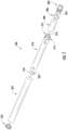
- FIG. 2 illustrates an exploded view of an aerosol delivery device 400 according to an example embodiment of the present disclosure.
- the aerosol delivery device 400 may include a control body 402 and a cartridge 404.
- the control body 402 may include an indicator 406 (e.g., an LED), a circuit board 408, an electrical power source 410 (e.g., a battery, which may be rechargeable), a flow sensor 412, a motor assembly 414, wiring 416, a coupler 418, and an outer body 420.
- the cartridge 404 may include a base 422, a piston 424, a reservoir 426, an atomizer 428, a mouthpiece 430, and an outer body 432.
- the base 422 of the cartridge 404 may be configured to releasably engage the coupler 418 of the control body 402 to form a mechanical and electrical connection therebetween.
- FIG. 3 illustrates a modified sectional view through the aerosol delivery device 400 as assembled. More particularly, FIG. 3 illustrates a flow path of air through the aerosol delivery device when a user draws on the mouthpiece 430.
- an airflow or flow of ambient air 434 may enter the aerosol delivery device 400 and travel past the flow sensor 412.
- the flow sensor may comprise a pressure sensor such that the air need not directly contact the sensor for a puff to be detected.
- the air 434 may then travel through the coupler 418 through one or more apertures 436 (see, FIG. 4 ), through the base 422, around the reservoir 426 and the atomizer 428, and out the mouthpiece 430.
- the air 434 may enter the aerosol delivery device 400 through the outer body 420 (e.g., through one or more apertures defined therein).
- the air may enter the aerosol delivery device at an alternate location.
- the air may enter through a longitudinal end of the aerosol delivery device opposite from the mouthpiece, though the coupler or the base, or at a location between the base and the mouthpiece. Accordingly, it should be understood that the particular airflow patterns described herein are provided for example purposes only.
- FIG. 4 illustrates an enlarged, exploded, partial view of the motor assembly 414 and the coupler 418.
- the motor assembly 414 may include an actuator 438 and a rod 440.
- the coupler 418 may include a receptacle 442 configured to receive and hold the actuator 438 of the motor assembly 414 in place.
- the actuator 438 may be configured to linearly displace the rod 440.
- the motor assembly 414 may comprise a linear motor in some embodiments.
- the motor assembly 414 may comprise a SQUIGGLE motor as sold by New Scale Technologies, Inc. of Victor, New York. Such a motor may produce both linear and rotary movement of the rod 440.
- the actuator 438 may linearly displace the rod 440 into the cartridge 404 such that the piston 424 presses against an aerosol precursor composition 444 in the reservoir 426.
- the reservoir 426 may define a pump housing and the actuator 438 may be configured to displace the piston 424 within the pump housing to dispense the aerosol precursor composition 426 therefrom. Accordingly, the aerosol precursor composition may be directed to the atomizer 428.
- FIG. 6 illustrates an enlarged partial perspective view of the atomizer 428.
- the atomizer 428 may include a fluid delivery tube 446, a heater disk 448, a cap 450, a heating element 452, and first and second terminals 454a,b.
- the heating element 452 and/or the first and second terminals 454a,b may comprise a printed circuit in some embodiments.
- the heating element 452 is imbedded in, or printed on the heater disk 448 in some embodiments.
- the first and second terminals 454a,b may be coupled to, imbedded in, or printed on the heater disk 448 in some embodiments.
- FIG. 7 illustrates an opposing enlarged partial perspective view of the atomizer 428 and the reservoir 426.
- the fluid delivery tube 446 may include an aperture 456 extending from the reservoir 426 toward the heating element 452.
- the aperture 456 may connect to a groove 458 defined in the fluid delivery tube 446 at an end thereof.
- a size, shape, and/or pattern of the heating element 452 may at least partially match that of the groove 458.
- the fluid delivery tube 446 and the cap 450 may cooperatively define a chamber 461 (see, e.g., FIG. 3 ) in which the heating element 452 is positioned and to which the aerosol precursor composition 444 is delivered.
- the aerosol precursor composition 444 may be directed into contact with the heating element 452 at the chamber 461 to ensure vaporization thereof.
- the flow sensor 412 detects a puff on the aerosol delivery device 400
- current from the electrical power source 410 may be directed through the terminals 454a,b to cause the heating element 452 to produce heat.
- the aerosol precursor composition directed through the aperture 456 and into the groove 458 may be heated and vaporized by the heating element 452 in the groove.
- the aerosol precursor composition 444 may be retained in the groove by the heater disk 448 and/or the heating element 452. Thereby, the aerosol precursor composition 444 and vapor produced by the heating element 452 may be forced to follow a path defined by the groove 458 which terminates at a round groove 462.
- the resultant vapor 460 may then exit the chamber 461 of the atomizer 428 through the round groove 462 and radially extending grooves 464 defined in the fluid delivery tube 446 and overlapping grooves 466 in the reservoir 426 as illustrated in FIGS. 6-9 .
- the chamber 461 may be configured to provide for optimal rates of release of the vapor 460 therefrom and into the air 434.
- the radially extending grooves 464 defined in the fluid delivery tube 446 and the overlapping grooves 466 in the reservoir 426 may be particularly sized and oriented so as to provide for a selected flow rate of the vapor from the chamber 461.
- grooves are described above as being employed to allow for outflow of vapor from the chamber, various other embodiments of outlet apertures such as one or more round holes may be employed in other embodiments.
- the housing may additionally define one or more inlet apertures in communication with the chamber.
- the inlet apertures may be configured to allow flow of air therethough into the chamber.
- air entering through the inlet apertures may mix with the vapor and exit through the outlet apertures (e.g., the grooves).
- the inlet apertures may be positioned such that air flowing through the aerosol delivery device is incident upon the inlet apertures (e.g., the inlet apertures may extend substantially parallel to a longitudinal axis of the aerosol delivery device and hence substantially parallel to the airflow therethrough).
- the inlet apertures may assist in removing the vapor from the chamber.
- Baffles may additionally be positioned in and/or around the chamber in order to direct air into the chamber and/or direct the vapor out of the chamber.
- valves may be provided at one or both of the inlet apertures and the outlet apertures. Such valves may passively or actively open and close to allow flow of air into the chamber and/or allow flow of vapor out of the chamber. Alternatively or additionally, the inlet apertures and/or the outlet apertures may be particularly sized to provide a desired flow of the vapor from the chamber while ensuring substantially complete vaporization of the aerosol precursor composition.
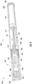
- FIG. 10 illustrates a sectional view through an aerosol delivery device 500 according to an additional example embodiment of the present disclosure.
- the aerosol delivery device 500 may include a control body 502 and a cartridge 504.
- the control body 502 may include an indicator 506 (e.g., an LED), an electrical power source 508 (e.g., a battery, which may be rechargeable), a flow sensor 510, a motor assembly 512 comprising an actuator 514 and a rod 516, a piston 518, a valve assembly 520, a pump housing 522, a coupler 524, and an outer body 526.
- an indicator 506 e.g., an LED
- an electrical power source 508 e.g., a battery, which may be rechargeable
- a flow sensor 510 e.g., a motor assembly 512 comprising an actuator 514 and a rod 516, a piston 518, a valve assembly 520, a pump housing 522, a coupler 524, and an outer
- the cartridge 504 may include a base 528, a reservoir 530, an atomizer 531 comprising a heating element 532 and a fluid delivery tube 536, a mouthpiece 534, and an outer body 538.
- the base 528 of the cartridge 504 may be configured to releasably engage the coupler 524 of the control body 502 to form a mechanical and electrical connection therebetween.
- FIG. 11 illustrates an additional sectional view through the aerosol delivery device 500. More particularly, FIG. 11 illustrates a flow path of air through the aerosol delivery device 500 when a user draws on the mouthpiece 534.
- an airflow or flow of ambient air 540 may enter the aerosol delivery device 500 and travel past the flow sensor 510.
- the ambient air 540 is illustrated as flowing past the electrical power source 508, in other embodiments the air may not flow past the electrical power source and/or the flow sensor may be positioned at an alternative location.
- the air 540 may then travel through the coupler 524 through one or more apertures 542 defined therethrough, through the base 528, around the reservoir 530 and the atomizer 531, and out the mouthpiece 534.
- the air 540 may enter the aerosol delivery device 500 through a longitudinal end thereof, opposite from the mouthpiece 534.
- the air may enter the aerosol delivery device at an alternate location.
- the air may enter through the coupler or the base, or at a location between the base and the mouthpiece. Accordingly, it should be understood that the particular airflow patterns described herein are provided for example purposes only.
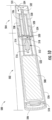
- FIG. 12 illustrates an enlarged partial sectional view through the aerosol delivery device 500.
- the actuator 514 may be configured to linearly displace the rod 516.
- the motor assembly 512 may comprise a linear motor in some embodiments.
- the motor assembly 512 may comprise a SQUIGGLE motor as sold by New Scale Technologies, Inc. of Victor, New York. Such a motor may produce both linear and rotary movement of the rod 516.
- the actuator 514 may linearly displace the rod 516 in a first direction (e.g., to the left in terms of the orientation illustrated in FIG. 12 ) such that the piston 518 retracts away from the cartridge 504 further into the pump housing 522. As illustrated in FIG. 12 , this movement may draw an aerosol precursor composition 544 out of the reservoir 530, through one or more one-way valves 546 of the valve assembly 520, and into the pump housing 522.
- the motor assembly 512 may be actuated such that the actuator 514 linearly displaces the rod 516 in a second direction (e.g., to the right in terms of the orientation illustrated in FIG. 12 ), opposite to the first direction, such that the piston 518 is directed toward the cartridge 504.
- the aerosol precursor composition 544 previously drawn into the pump housing 522 may be expelled through one or more second one-way valves 548 of the valve assembly 520.
- the first one-way valves 546 may only allow flow into the pump housing 522
- the second one-way valves 548 may only allow flow out of the pump housing.
- the device may comprise at least two one-way valves opening in opposing directions to alternatively allow aerosol precursor composition out of the reservoir and into the atomizer.
- the aerosol precursor composition 544 may be directed to the atomizer 531.
- the aerosol precursor composition 544 may be directed through the fluid delivery tube 536 to the heating element 532.
- the heating element 532 may define a tubular configuration whereby the aerosol precursor composition 544 may be directed therethrough and vaporized therein.
- the heating element 532 may be aligned with, or otherwise in fluid communication with, the fluid delivery tube 536 such that the aerosol precursor composition 544 directed through the fluid delivery tube is also directed through the heating element.
- the atomizer 531 may comprise a fluid delivery tube 536 (which may be a capillary tube) that is adjacent to and co-linear with a substantially tubular heating element 532. Accordingly, by providing the heating element 532 with the tubular configuration, the atomizer 531 may define a chamber 549 (see, FIG. 12 ) to which the aerosol precursor composition 544 is delivered. Thus, issues with respect to the aerosol precursor composition 544 being directed into the air 540 and to a user without being vaporized may be avoided. In this regard, the aerosol precursor composition 544 may be directed into contact with the heating element 532 at the chamber 549 to ensure vaporization thereof.
- a selectively permeable cover may be included at an outlet aperture 551 at or near the terminal end of the heating element 532 to allow exit of formed vapor 550 and substantially disallow exit of liquid aerosol precursor composition 544. Accordingly, leakage of any of the aerosol precursor composition which has not been vaporized may be avoided.
- the flow sensor 510 when the flow sensor 510 detects a puff on the aerosol delivery device 500, current from the electrical power source 508 may be directed to the heating element 532 to produce heat. Accordingly, the aerosol precursor composition 544 directed thereto may be heated and vaporized to define an aerosol or vapor 550. The vapor 550 may then exit the chamber 549 through the outlet aperture 551, mix with the air 540, and exit through the mouthpiece 534.
- the chamber 549 may be configured to provide for optimal rates of release of the vapor 550 therefrom and into the air 540.
- the outlet aperture 551 may be particularly sized and oriented so as to provide for a selected flow rate of the vapor 550 from the chamber 549.
- the outlet aperture 551 is illustrated as defining around configuration, various other embodiments of outlet apertures such as a plurality of apertures and/or non-circular apertures may be employed in other embodiments.
- the atomizer may additionally define one or more inlet apertures in communication with the chamber.
- the inlet apertures may be configured to allow flow of air therethough into the chamber.
- air entering through the inlet apertures may mix with the vapor and exit through the outlet aperture(s).
- the inlet apertures may be positioned such that air flowing through the aerosol delivery device is incident upon the inlet apertures (e.g., the inlet apertures may extend substantially parallel to a longitudinal axis of the aerosol delivery device and hence substantially parallel to the airflow therethrough).
- the inlet apertures may assist in removing the vapor from the chamber.
- Baffles may additionally be positioned in and/or around the chamber in order to direct air into the chamber and/or direct the vapor out of the chamber.
- valves may be provided at one or both of the inlet apertures and the outlet apertures. Such valves may passively or actively open and close to allow flow of air into the chamber and/or allow flow of vapor out of the chamber. Alternatively or additionally, the inlet apertures and/or the outlet apertures may be particularly sized to provide a desired flow of the vapor from the chamber while ensuring substantially complete vaporization of the aerosol precursor composition.
- the atomizer 531 may additionally include a support member 533.
- the support member 533 may be configured to support the heating element 532 in a position adjacent an end of the fluid delivery tube 536 and, for example, co-linear therewith, so as to provide a smooth flow path.
- the support member 533 may comprise an insulator or insulating material that insulates additional components of the cartridge 504 (e.g., the outer body 538) from heat produced by the heating element to substantially prevent damage thereto.
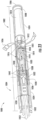
- FIG. 14 illustrates a sectional view through an aerosol delivery device 600 according to an additional example embodiment of the present disclosure.
- the aerosol delivery device 600 may include a control body 602 and a cartridge 604.
- the control body 602 may include an indicator 606 (e.g., an LED), an electrical power source 608 (e.g., a battery, which may be rechargeable), a flow sensor 610, a motor assembly 612 comprising an actuator 614 and a rod 616, a piston 618, a valve assembly 620, a pump housing 622, a coupler 624, an atomizer 626 comprising a heating element 627, and an outer body 628.
- an indicator 606 e.g., an LED
- an electrical power source 608 e.g., a battery, which may be rechargeable
- a flow sensor 610 e.g., a motor assembly 612 comprising an actuator 614 and a rod 616, a piston 618, a valve assembly 620, a
- the cartridge 604 may include a base 630, a reservoir 632, a mouthpiece 634, and an outer body 636.
- the base 630 of the cartridge 604 may be configured to releasably engage the coupler 624 of the control body 602 to form a mechanical and electrical connection therebetween.
- FIG. 15 illustrates an additional sectional view through the aerosol delivery device 600. More particularly, FIG. 15 illustrates a flow path of air through the aerosol delivery device 600 when a user draws on the mouthpiece 634.
- an airflow or flow of ambient air 638 may enter the aerosol delivery device 600 and travel past the flow sensor 610.
- the ambient air 638 is illustrated as flowing past the electrical power source 608, in other embodiments the air may not flow past the electrical power source and/or the flow sensor may be positioned at an alternative location.
- the air 638 may then travel through the coupler 624 through one or more apertures 640 defined therethrough, through the base 630, around the reservoir 632, and out the mouthpiece 634.
- the air 638 may enter the aerosol delivery device 600 through a longitudinal end thereof, opposite from the mouthpiece 634.
- the air may enter the aerosol delivery device at an alternate location.
- the air may enter through the coupler or the base, or at a location between the base and the mouthpiece. Accordingly, it should be understood that the particular airflow patterns described herein are provided for example purposes only.
- FIG. 16 illustrates an enlarged partial sectional view through the aerosol delivery device 600.
- the actuator 614 may be configured to linearly displace the rod 616.
- the motor assembly 612 may comprise a linear motor in some embodiments.
- the motor assembly 612 may comprise a SQUIGGLE motor as sold by New Scale Technologies, Inc. of Victor, New York. Such a motor may produce both linear and rotary movement of the rod 616.
- the actuator 614 may linearly displace the rod 616 in a first direction (e.g., to the left in terms of the orientation illustrated in FIG. 16 ) such that the piston 618 retracts away from the cartridge 604 further into the pump housing 622. As illustrated in FIG. 16 , this movement may draw an aerosol precursor composition 642 through one or more one-way valves 644 of the valve assembly 620 into the pump housing 622.
- the motor assembly 612 may be actuated such that the actuator 614 linearly displaces the rod 616 in a second direction (e.g., to the right in terms of the orientation illustrated in FIG. 16 ), opposite to the first direction, such that the piston 618 is directed toward the cartridge 604.
- the aerosol precursor composition 642 previously drawn into the pump housing 622 may be expelled to the atomizer 626.
- the atomizer 626 may further comprise a fluid delivery tube 646.
- the aerosol precursor composition 642 may be directed through the fluid delivery tube 646 to the heating element 627.
- the fluid delivery tube 646 may be defined at least in part by the pump housing 622.
- the atomizer 626 may comprise a housing 647 defining a chamber 649 in which the heating element 627 is positioned and to which the aerosol precursor composition 642 is delivered.
- the aerosol precursor composition 642 may be directed into contact with the heating element 627 at the chamber 649 to ensure vaporization thereof.
- the flow sensor 610 detects a puff on the aerosol delivery device 600
- current from the electrical power source 608 may be directed to the heating element 627 to produce heat.
- the aerosol precursor composition 642 directed thereto may be heated and vaporized to define an aerosol or vapor 648 which exits the chamber 649 through one or more outlet apertures 651 defined in the housing 647.
- the vapor 648 may then mix with the air 638 and exit through the mouthpiece 634.
- the chamber 649 may be configured to provide for optimal rates of release of the vapor 648 (see, e.g., FIG. 17 ) therefrom and into the air 638.
- the outlet apertures 651 may be particularly sized and oriented so as to provide for a selected flow rate of the vapor 648 from the chamber 649.
- the outlet apertures 651 are illustrated as defining a round configuration, various other embodiments of outlet apertures such as non-circular apertures and/or a singular aperture may be employed in other embodiments.
- the housing 647 may additionally define one or more inlet apertures 653 in communication with the chamber 649.
- the inlet apertures 653 may be configured to allow flow of air therethough into the chamber 649.
- air entering through the inlet apertures 653 may mix with the vapor 648 (see, e.g., FIG. 17 ) and exit through the outlet apertures 651.
- the inlet apertures 653 may be positioned such that air flowing through the aerosol delivery device 600 is incident upon the inlet apertures (e.g., the inlet apertures may extend substantially parallel to a longitudinal axis of the aerosol delivery device and hence substantially parallel to the airflow therethrough).
- the inlet apertures 653 may assist in removing the vapor 648 from the chamber 649.
- Baffles may additionally be positioned in and/or around the chamber in order to direct air into the chamber and/or direct the vapor out of the chamber.
- valves may be provided at one or both of the inlet apertures and the outlet apertures. Such valves may passively or actively open and close to allow flow of air into the chamber and/or allow flow of vapor out of the chamber. Alternatively or additionally, the inlet apertures and/or the outlet apertures may be particularly sized to provide a desired flow of the vapor from the chamber while ensuring substantially complete vaporization of the aerosol precursor composition.
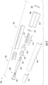
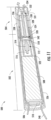
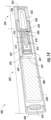
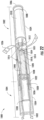
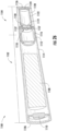
- FIG. 18 illustrates a sectional view through an aerosol delivery device 700 according to an additional example embodiment of the present disclosure.
- the aerosol delivery device 700 may include a control body 702 and a cartridge 704.
- the control body 702 may include an indicator 706 (e.g., an LED), an electrical power source 708 (e.g., a battery, which may be rechargeable), a flow sensor 710, a motor assembly 712 comprising an actuator 714 and a rod 716, a piston 718, a valve assembly 720, a pump housing 722, a coupler 724, and an outer body 726.
- an indicator 706 e.g., an LED
- an electrical power source 708 e.g., a battery, which may be rechargeable
- a flow sensor 710 e.g., a motor assembly 712 comprising an actuator 714 and a rod 716, a piston 718, a valve assembly 720, a pump housing 722, a coupler 724, and an outer body 7
- the cartridge 704 may include a base 728, a reservoir 730 that may include an aerosol precursor bag 732 received therein, an atomizer 733 comprising a heating element 734 and a fluid delivery tube 735, a mouthpiece 736, and an outer body 738.
- the base 728 of the cartridge 704 may be configured to releasably engage the coupler 724 of the control body 702 to form a mechanical and electrical connection therebetween.
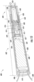
- FIG. 19 illustrates an additional sectional view through the aerosol delivery device 700. More particularly, FIG. 19 illustrates a flow path of air through the aerosol delivery device 700 when a user draws on the mouthpiece 736. As illustrated, an airflow or flow of ambient air 740 may enter the aerosol delivery device 700 and travel past the flow sensor 710. Although the ambient air 740 is illustrated as flowing past the electrical power source 708, in other embodiments the air may not flow past the electrical power source and/or the flow sensor may be positioned at an alternative location. The air 740 may then travel through the coupler 724 through one or more apertures 742 defined therethrough, through the base 728, around the reservoir 730, and out the mouthpiece 736.
- the air 740 may enter the aerosol delivery device 700 through a longitudinal end thereof, opposite from the mouthpiece 736.
- the air may enter the aerosol delivery device at an alternate location.
- the air may enter through the coupler or the base, or at a location between the base and the mouthpiece. Accordingly, it should be understood that the particular airflow patterns described herein are provided for example purposes only.
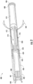
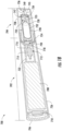
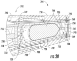
- FIG. 20 illustrates an enlarged partial sectional view through the aerosol delivery device 700.
- the actuator 714 may be configured to linearly displace the rod 716.
- the motor assembly 712 may comprise a linear motor in some embodiments.
- the motor assembly 712 may comprise a SQUIGGLE motor as sold by New Scale Technologies, Inc. of Victor, New York. Such a motor may produce both linear and rotary movement of the rod 714.
- the actuator 714 may linearly displace the rod 716 in a first direction (e.g., to the right in terms of the orientation illustrated in FIG. 20 ) such that the piston 718 is directed toward the cartridge 704.
- the piston 718 may displace air (or another fluid) from the pump housing 722 and through the valve assembly 720.
- the air may enter the reservoir 730 and apply pressure to the aerosol precursor bag 732 to dispense an aerosol precursor composition 744 as discussed below.
- the aerosol precursor bag 732 may assist in dispensing the aerosol precursor composition 744 from the reservoir 730.
- the aerosol precursor bag 732 may shrink or deform as the aerosol precursor composition 744 is dispensed therefrom, whereas use of a rigid container may resist deformation and thereby not dispense the aerosol precursor composition.
- the aerosol precursor bag 732 may comprise an elastomeric material (e.g., rubber).
- the aerosol precursor composition 744 retained in the aerosol precursor bag 732 may be expelled to the atomizer 733.
- the aerosol precursor composition 744 may be directed through the fluid delivery tube 735 to the heating element 734.
- the atomizer 733 may comprise a housing 745 defining a chamber 747 in which the heating element 734 is positioned and to which the aerosol precursor composition 744 is delivered.
- the aerosol precursor composition 744 may be directed into contact with the heating element 734 at the chamber 747 to ensure vaporization thereof.
- the flow sensor 710 detects a puff on the aerosol delivery device 700
- current from the electrical power source 708 may be directed to the heating element 734 to produce heat.
- the aerosol precursor composition 744 directed thereto may be heated and vaporized to define an aerosol or vapor 748 which exits the chamber 747 through one or more outlet apertures 749 defined in the housing 745.
- the vapor 748 may then mix with the air 740 and exit through the mouthpiece 736.
- the chamber 747 may be configured to provide for optimal rates of release of the vapor 748 therefrom and into the air 740.
- the outlet apertures 749 may be particularly sized and oriented so as to provide for a selected flow rate of the vapor 748 from the chamber 747.
- the outlet apertures 749 are illustrated as defining a round configuration, various other embodiments of outlet apertures such as non-circular apertures and/or a singular aperture may be employed in other embodiments.
- the atomizer may additionally define one or more inlet apertures in communication with the chamber.
- the inlet apertures may be configured to allow flow of air therethough into the chamber.
- air entering through the inlet apertures may mix with the vapor and exit through the outlet aperture(s).
- the inlet apertures may be positioned such that air flowing through the aerosol delivery device is incident upon the inlet apertures (e.g., the inlet apertures may extend substantially parallel to a longitudinal axis of the aerosol delivery device and hence substantially parallel to the airflow therethrough).
- the inlet apertures may assist in removing the vapor from the chamber.
- Baffles may additionally be positioned in and/or around the chamber in order to direct air into the chamber and/or direct the vapor out of the chamber.
- valves may be provided at one or both of the inlet apertures and the outlet apertures. Such valves may passively or actively open and close to allow flow of air into the chamber and/or allow flow of vapor out of the chamber. Alternatively or additionally, the inlet apertures and/or the outlet apertures may be particularly sized to provide a desired flow of the vapor from the chamber while ensuring substantially complete vaporization of the aerosol precursor composition.
- the actuator 714 of the motor assembly 712 may retract the piston 718 away from the cartridge 704 further into the pump housing 722 in a second direction (e.g., to the left in terms of the orientation illustrated in FIG. 20 ), opposite to the first direction.
- One or more one-way valves 750 of the valve assembly 720 may prevent air from being drawn out of the reservoir 730 during this movement. Accordingly, the piston 718 may be returned to the retracted position, where it may remain until another puff on the aerosol delivery device 700 is detected by the flow sensor 710.
- the motor assembly may employ mechanical force (e.g., by contacting the aerosol precursor bag with the rod or the piston) to directly expel the aerosol precursor composition from the aerosol precursor bag.
- FIG. 21 illustrates an exploded view of an aerosol delivery device 1000 according to an additional example embodiment of the present disclosure, which is not covered by the claims.
- the aerosol delivery device 1000 may include a control body 1002 and a cartridge 1004.
- the control body 1002 may include an indicator 1006 (e.g., an LED), a circuit or circuit board 1008, an electrical power source 1010 (e.g., a battery, which may be rechargeable), a flow sensor 1012, an atomizer 1014, wiring 1016, a pump housing 1018, a pump 1020 (e.g., a piezoelectric pump sold by MicroFab Technologies, Inc. of Plano, Texas), a coupler 1022, and an outer body 1024.
- an indicator 1006 e.g., an LED
- a circuit or circuit board 1008 an electrical power source 1010 (e.g., a battery, which may be rechargeable)
- a flow sensor 1012 e.g., a battery, which may be rechargeable
- the cartridge 1004 may include a base 1026, a reservoir 1028, a lid 1030 that encloses the reservoir, a mouthpiece 1032, and an outer body 1034.
- the base 1026 of the cartridge 1004 may be configured to releasably engage the coupler 1022 of the control body 1002 to form a mechanical and electrical connection therebetween.
- FIG. 22 illustrates a modified sectional view through the aerosol delivery device 1000. More particularly, FIG. 22 illustrates a flow path of air through the aerosol delivery device 1000 when a user draws on the mouthpiece 1032. As illustrated, an airflow or flow of ambient air 1036 may enter the aerosol delivery device 1000 and travel past the flow sensor 1012. The air 1036 may then travel around the atomizer 1014 and the pump housing 1018, through the coupler 1022 through one or more apertures 1038 defined therethrough, through the base 1026, around the reservoir 1028, and out the mouthpiece 1032.
- the air 1036 may enter the aerosol delivery device 1000 through the outer body 1024 (e.g., through one or more apertures defined therein).
- the air may enter the aerosol delivery device at an alternate location.
- the air may enter through a longitudinal end of the aerosol delivery device opposite from the mouthpiece, though the coupler or the base, or at a location between the base and the mouthpiece. Accordingly, it should be understood that the particular airflow patterns described herein are provided for example purposes only.
- the pump 1020 When the flow sensor 1012 detects the puff, the pump 1020 may be actuated.
- the coupler 1022 may include a receptacle 1040 configured to receive and hold the pump 1020. Accordingly, as illustrated in FIG. 22 , when the control body 1002 is coupled to the cartridge 1004, the pump 1020 may engage the reservoir 1028.
- an aerosol precursor composition 1042 in the reservoir 1028 may be pumped toward the atomizer 1014.
- the pump 1020 may include a driver device configured to produce a pressure wave that forces the aerosol precursor composition 1042 therethrough.
- the driver device may comprise a piezoelectric actuator described, by way of example, in U.S. Patent No. 5,053,100 to Hayes et al. , which is incorporated herein by reference in its entirety.
- FIG. 24 illustrates an enlarged modified sectional view of the atomizer 1014.
- the atomizer 1014 may include a fluid delivery tube 1044, a heating element 1046, and a cap 1048.
- the fluid delivery tube 1044 may include an aperture 1050 configured to receive the aerosol precursor composition 1042 from the pump 1020 and direct the aerosol precursor composition to the heating element 1046.
- FIG. 25 illustrates an opposing enlarged partial perspective view of the heating element 1046 and the cap 1048.
- current from the electrical power source 1008 may be directed to the heating element 1046 to produce heat.
- current may be directly delivered to the heating element 1046, or current may directed to terminals coupled to the heating element.
- the aerosol precursor composition 1042 directed through the aperture 1050 in the fluid delivery tube 1044 may be heated and vaporized by the heating element 1046 to define an aerosol or vapor 1052.
- the fluid delivery tube 1044 and the cap 1048 may cooperatively define a chamber 1051 (see, FIG.
- the heating element 1046 is positioned and to which the aerosol precursor composition 1042 is delivered.
- the aerosol precursor composition 1042 may be directed into contact with the heating element 1046 at the chamber 1051 to ensure vaporization thereof.
- the vapor 1052 (see, FIG. 23 ) may then exit the atomizer 1014 through radially extending grooves 1054 in the cap 1048 (see, FIG. 25 ) and intermix and travel with the air 1036 to the mouthpiece 1032.
- the chamber 1051 may be configured to provide for optimal rates of release of the vapor 1052 therefrom and into the air 1036.
- the radially extending grooves 1054 defined in the cap may be particularly sized and oriented so as to provide for a selected flow rate of the vapor 1052 (see, FIG. 23 ) from the chamber 1051.
- grooves are described above as being employed to allow for outflow of vapor from the chamber, various other embodiments of outlet apertures such as one or more round holes may be employed in other embodiments.
- the housing may additionally define one or more inlet apertures in communication with the chamber.
- the inlet apertures may be configured to allow flow of air therethough into the chamber.
- air entering through the inlet apertures may mix with the vapor and exit through the outlet apertures (e.g., the grooves).
- the inlet apertures may be positioned such that air flowing through the aerosol delivery device is incident upon the inlet apertures (e.g., the inlet apertures may extend substantially parallel to a longitudinal axis of the aerosol delivery device and hence substantially parallel to the airflow therethrough).
- the inlet apertures may assist in removing the vapor from the chamber.
- Baffles may additionally be positioned in and/or around the chamber in order to direct air into the chamber and/or direct the vapor out of the chamber.
- valves may be provided at one or both of the inlet apertures and the outlet apertures. Such valves may passively or actively open and close to allow flow of air into the chamber and/or allow flow of vapor out of the chamber. Alternatively or additionally, the inlet apertures and/or the outlet apertures may be particularly sized to provide a desired flow of the vapor from the chamber while ensuring substantially complete vaporization of the aerosol precursor composition.
- FIG. 26 illustrates a sectional view through an aerosol delivery device 1100 according to an additional example embodiment of the present disclosure, which is not covered by the claims.
- the aerosol delivery device 1100 may include a control body 1102 and a cartridge 1104.
- the control body 1102 may include an indicator 1106 (e.g., an LED), an electrical power source 1108 (e.g., a battery, which may be rechargeable), a flow sensor 1110, a coupler 1112, and an outer body 1114.
- the cartridge 1104 may include a base 1116, an atomizer 1118 (e.g., comprising a heating element 1119), a pump 1120 (e.g., a micropump on a silicon chip as sold by Debiotech of Lausanne, Switzerland), a reservoir 1122, a lid 1124 that encloses the reservoir, a mouthpiece 1126, and an outer body 1128.
- the base 1116 of the cartridge 1104 may be configured to releasably engage the coupler 1112 of the control body 1102 to form a mechanical and electrical connection therebetween.
- FIG. 27 illustrates an additional sectional view through the aerosol delivery device 1100. More particularly, FIG. 27 illustrates a flow path of air through the aerosol delivery device 1100 when a user draws on the mouthpiece 1126. As illustrated, an airflow or flow of ambient air 1130 may enter the aerosol delivery device 1100 and travel past the flow sensor 1110. Although the ambient air 1130 is illustrated as flowing past the electrical power source 1108, in other embodiments the air may not flow past the electrical power source and/or the flow sensor may be positioned at an alternative location. The air 1130 may then travel through the coupler 1112 through one or more apertures 1132 defined therethrough, through the base 1116, around the atomizer 1118 and the reservoir 1122, and out the mouthpiece 1126.
- the air 1130 may enter the aerosol delivery device 1100 through a longitudinal end thereof, opposite from the mouthpiece 1126.
- the air may enter the aerosol delivery device at an alternate location.
- the air may enter through the coupler or the base, or at a location between the base and the mouthpiece. Accordingly, it should be understood that the particular airflow patterns described herein are provided for example purposes only.
- FIG. 28 illustrates an enlarged partial sectional view of the aerosol delivery device 1100.
- the flow sensor 1110 detects the puff
- current may be applied to the pump 1120.
- an aerosol precursor composition 1134 retained in the reservoir 1122 may be expelled toward the atomizer 1118.
- the atomizer 1118 may further comprise a housing 1133 defining a chamber 1135 in which the heating element 1119 is positioned and to which the aerosol precursor composition 1134 is delivered.
- the aerosol precursor composition 1134 may be directed into contact with the heating element 1119 at the chamber 1135 to ensure vaporization thereof.
- the flow sensor 1110 detects a puff on the aerosol delivery device 1100
- current from the electrical power source 1108 may be directed to the heating element 1119 to produce heat.
- the aerosol precursor composition 1134 directed thereto may be heated and vaporized to define an aerosol or vapor 1136.
- the resulting vapor 1136 may then exit the chamber 1135 through one or more outlet apertures 1137, mix with the air 1130, and exit through the mouthpiece 1126.
- the chamber 1135 may be configured to provide for optimal rates of release of the vapor 1136 therefrom and into the air 1130.
- the outlet apertures 1137 may be particularly sized and oriented so as to provide for a selected flow rate of the vapor 1136 from the chamber 1135.
- the outlet apertures 1137 are illustrated as defining a round configuration, various other embodiments of outlet apertures such as non-circular apertures and/or a singular aperture may be employed in other embodiments.
- the atomizer may additionally define one or more inlet apertures in communication with the chamber.
- the inlet apertures may be configured to allow flow of air therethough into the chamber.
- air entering through the inlet apertures may mix with the vapor and exit through the outlet aperture(s).
- the inlet apertures may be positioned such that air flowing through the aerosol delivery device is incident upon the inlet apertures (e.g., the inlet apertures may extend substantially parallel to a longitudinal axis of the aerosol delivery device and hence substantially parallel to the airflow therethrough).
- the inlet apertures may assist in removing the vapor from the chamber.
- Baffles may additionally be positioned in and/or around the chamber in order to direct air into the chamber and/or direct the vapor out of the chamber.
- valves may be provided at one or both of the inlet apertures and the outlet apertures. Such valves may passively or actively open and close to allow flow of air into the chamber and/or allow flow of vapor out of the chamber. Alternatively or additionally, the inlet apertures and/or the outlet apertures may be particularly sized to provide a desired flow of the vapor from the chamber while ensuring substantially complete vaporization of the aerosol precursor composition.
- connectors between the cartridge and control body allow for fluid dispensing to an atomizer and additionally provide an electrical connection therebetween, such that, for example, power from an electrical power source may be provided to the atomizer.
- the base and coupler are configured such that a rod may extend from the control body through the coupler and the base to displace a piston in the cartridge.
- the aerosol delivery devices 500, 600, 700, 1000, 1100 illustrated in FIGS. 10-28 include connections configured to direct the aerosol precursor composition therethrough.
- the aerosol precursor composition is directed from the cartridge through the base and into the control body through the coupler.
- the connectors may also be configured to allow for airflow therethrough.
- the cartridge may be configured to receive an airflow from the control body through the coupler and the base.
- atomizers may be employed to vaporize the aerosol precursor composition in the embodiments of aerosol delivery devices described above.
- Such atomizers may include flat heaters, wound wire surfaces, micro heaters (e.g., embodied on a chip) glass plates, lasers, resistive heaters, and any other shape and embodiment of heater.
- the materials employed in the first heating elements and the second heating elements may vary.
- the materials described above with respect to wire coil heating elements may be employed.
- Various other materials which may be employed in the heating elements described herein may include platinum or a platinum-coated materials and resistive inks (e.g., printed on a ceramic material).
- Certain aerosol delivery devices described herein may avoid certain issues associated with conventional aerosol delivery devices that employ a wick.
- use of a wick may cause separation of the ingredients of an aerosol precursor composition.
- use of a wick to transfer the aerosol precursor composition from a substrate to a heating element may result in leakage. Accordingly, the embodiments of the aerosol delivery devices disclosed herein may provide these and/or other advantages.
- aerosol delivery devices disclosed herein are generally described as including a cartridge (e.g., a replaceable cartridge) and a control body (e.g., a reusable control body), various other embodiments may be employed.
- the aerosol delivery devices may include more than two-pieces.
- the aerosol delivery device may define an integral, one-piece configuration.
- a method for aerosolization in an aerosol delivery device may include directing an airflow from a control body through a cartridge comprising a reservoir at least partially filled with an aerosol precursor composition at operation 1402. Further, the method may include dispensing the aerosol precursor composition from the reservoir to an atomizer comprising a heating element with a positive displacement apparatus at operation 1404. The method may additionally include heating the aerosol precursor composition dispensed from the reservoir with the heating element to produce an aerosol at operation 1406.
- dispensing the aerosol precursor composition at operation 1404 may comprise displacing a piston within a pump housing with an actuator.
- a motor assembly including, for example, the actuator and a rod may displace the piston.
- the actuator may comprise a linear motor in some embodiments.
- the motor assembly may comprise a SQUIGGLE motor as sold by New Scale Technologies, Inc. of Victor, New York. Such a motor may produce both linear and rotary movement of the rod.
- displacing the piston within the pump housing may comprise displacing the piston within the reservoir. In other words, the reservoir may define the pump housing.
- displacing the piston within the pump housing may comprise displacing a fluid from the pump housing into the reservoir.
- Displacing the fluid from the pump housing into the reservoir may comprise displacing the aerosol precursor composition from an aerosol precursor bag in the reservoir.
- displacing the piston within the pump housing may comprise moving the piston in a first direction to draw the aerosol precursor composition from the reservoir into the pump housing and moving the piston in an opposing second direction to direct the aerosol precursor composition from the pump housing to the atomizer.
- the method may include preventing flow of the aerosol precursor composition from the atomizer to the pump housing and preventing flow of the aerosol precursor composition from the pump housing to the reservoir with a valve assembly.
- dispensing the aerosol precursor composition from the reservoir to the atomizer at operation 1404 may comprise delivering the aerosol precursor composition through a fluid delivery tube to the heating element.
- Delivering the aerosol precursor composition through the fluid delivery tube to the heating element may comprise delivering the aerosol precursor composition to a groove defined in an end of the fluid delivery tube.
- heating the aerosol precursor composition at operation 1406 may comprise heating the aerosol precursor composition in the groove.
- heating the aerosol precursor composition at operation 1406 may comprise heating the aerosol precursor composition in a chamber.
Landscapes
- Health & Medical Sciences (AREA)
- Engineering & Computer Science (AREA)
- Veterinary Medicine (AREA)
- Anesthesiology (AREA)
- Biomedical Technology (AREA)
- Heart & Thoracic Surgery (AREA)
- Hematology (AREA)
- Life Sciences & Earth Sciences (AREA)
- Animal Behavior & Ethology (AREA)
- General Health & Medical Sciences (AREA)
- Public Health (AREA)
- Bioinformatics & Cheminformatics (AREA)
- Pulmonology (AREA)
- Mechanical Engineering (AREA)
- Chemical & Material Sciences (AREA)
- General Engineering & Computer Science (AREA)
- Thermal Sciences (AREA)
- Combustion & Propulsion (AREA)
- Physics & Mathematics (AREA)
- Chemical Kinetics & Catalysis (AREA)
- General Chemical & Material Sciences (AREA)
- Nozzles (AREA)
- Containers And Packaging Bodies Having A Special Means To Remove Contents (AREA)
- Medicinal Preparation (AREA)
- Catching Or Destruction (AREA)
Priority Applications (1)
| Application Number | Priority Date | Filing Date | Title |
|---|---|---|---|
| PL14799607.8T PL3062645T5 (pl) | 2013-10-31 | 2014-10-29 | Urządzenie do dostarczania aerozolu obejmujące mechanizm wyporowy do dostarczania aerozolu |
Applications Claiming Priority (3)
| Application Number | Priority Date | Filing Date | Title |
|---|---|---|---|
| US201361897917P | 2013-10-31 | 2013-10-31 | |
| US14/309,282 US9717276B2 (en) | 2013-10-31 | 2014-06-19 | Aerosol delivery device including a positive displacement aerosol delivery mechanism |
| PCT/US2014/062803 WO2015066121A1 (en) | 2013-10-31 | 2014-10-29 | Aerosol delivery device including a positive displacement aerosol delivery mechanism |
Publications (3)
| Publication Number | Publication Date |
|---|---|
| EP3062645A1 EP3062645A1 (en) | 2016-09-07 |
| EP3062645B1 EP3062645B1 (en) | 2018-05-02 |
| EP3062645B2 true EP3062645B2 (en) | 2023-08-30 |
Family
ID=52994027
Family Applications (3)
| Application Number | Title | Priority Date | Filing Date |
|---|---|---|---|
| EP14799607.8A Active EP3062645B2 (en) | 2013-10-31 | 2014-10-29 | Aerosol delivery device including a positive displacement aerosol delivery mechanism |
| EP14799610.2A Active EP3062646B1 (en) | 2013-10-31 | 2014-10-29 | Aerosol delivery device including a pressure-based aerosol delivery mechanism |
| EP14802241.1A Pending EP3062647A1 (en) | 2013-10-31 | 2014-10-29 | Aerosol delivery device including a bubble jet head and related method |
Family Applications After (2)
| Application Number | Title | Priority Date | Filing Date |
|---|---|---|---|
| EP14799610.2A Active EP3062646B1 (en) | 2013-10-31 | 2014-10-29 | Aerosol delivery device including a pressure-based aerosol delivery mechanism |
| EP14802241.1A Pending EP3062647A1 (en) | 2013-10-31 | 2014-10-29 | Aerosol delivery device including a bubble jet head and related method |
Country Status (10)
| Country | Link |
|---|---|
| US (6) | US10292424B2 (ko) |
| EP (3) | EP3062645B2 (ko) |
| JP (10) | JP6546589B2 (ko) |
| KR (10) | KR102612319B1 (ko) |
| CN (6) | CN114431533A (ko) |
| DE (1) | DE202014011551U1 (ko) |
| ES (2) | ES2682326T5 (ko) |
| PL (2) | PL3062645T5 (ko) |
| RU (3) | RU2666502C2 (ko) |
| WO (3) | WO2015066136A1 (ko) |
Families Citing this family (225)
| Publication number | Priority date | Publication date | Assignee | Title |
|---|---|---|---|---|
| US20160345631A1 (en) | 2005-07-19 | 2016-12-01 | James Monsees | Portable devices for generating an inhalable vapor |
| US20150328415A1 (en) * | 2014-05-19 | 2015-11-19 | R.J. Reynolds Tobacco Company | Cartridge vaporizer in a personal vaporizer unit |
| US10517530B2 (en) | 2012-08-28 | 2019-12-31 | Juul Labs, Inc. | Methods and devices for delivering and monitoring of tobacco, nicotine, or other substances |
| US10279934B2 (en) | 2013-03-15 | 2019-05-07 | Juul Labs, Inc. | Fillable vaporizer cartridge and method of filling |
| US10638792B2 (en) | 2013-03-15 | 2020-05-05 | Juul Labs, Inc. | Securely attaching cartridges for vaporizer devices |
| ES2856448T3 (es) | 2013-05-06 | 2021-09-27 | Juul Labs Inc | Formulaciones de sal de nicotina para cigarrillos electrónicos y método de suministro de nicotina |
| CN111642812A (zh) | 2013-06-14 | 2020-09-11 | 尤尔实验室有限公司 | 电子汽化设备中的具有单独的可汽化材料的多个加热元件 |
| USD741001S1 (en) * | 2013-07-16 | 2015-10-13 | Fontem Holdings 4 B.V. | Nozzle |
| US10292424B2 (en) * | 2013-10-31 | 2019-05-21 | Rai Strategic Holdings, Inc. | Aerosol delivery device including a pressure-based aerosol delivery mechanism |
| US10980273B2 (en) | 2013-11-12 | 2021-04-20 | VMR Products, LLC | Vaporizer, charger and methods of use |
| KR102471383B1 (ko) | 2013-12-05 | 2022-11-25 | 쥴 랩스, 인크. | 에어로졸 장치를 위한 니코틴 액제 및 그 방법 |
| US10159282B2 (en) | 2013-12-23 | 2018-12-25 | Juul Labs, Inc. | Cartridge for use with a vaporizer device |
| USD842536S1 (en) | 2016-07-28 | 2019-03-05 | Juul Labs, Inc. | Vaporizer cartridge |
| HUE053511T2 (hu) | 2013-12-23 | 2021-07-28 | Juul Labs Int Inc | Párologtató eszközt tartalmazó rendszer |
| US20160366947A1 (en) | 2013-12-23 | 2016-12-22 | James Monsees | Vaporizer apparatus |
| US10058129B2 (en) | 2013-12-23 | 2018-08-28 | Juul Labs, Inc. | Vaporization device systems and methods |
| US10076139B2 (en) | 2013-12-23 | 2018-09-18 | Juul Labs, Inc. | Vaporizer apparatus |
| USD825102S1 (en) | 2016-07-28 | 2018-08-07 | Juul Labs, Inc. | Vaporizer device with cartridge |
| CN106455705A (zh) * | 2014-01-22 | 2017-02-22 | 方特慕控股第私人有限公司 | 用于吸烟欲望救济的方法和装置 |
| NZ722807A (en) | 2014-02-10 | 2019-05-31 | Philip Morris Products Sa | Cartridge with a heater assembly for an aerosol-generating system |
| KR102377636B1 (ko) | 2014-02-10 | 2022-03-24 | 필립모리스 프로덕츠 에스.에이. | 에어로졸 발생 시스템용 유체 투과성 히터 조립체 및 에어로졸 발생 시스템용 유체 투과성 히터를 조립하기 위한 방법 |
| CA2936273C (en) | 2014-02-10 | 2021-12-28 | Philip Morris Products S.A. | Cartridge for an aerosol-generating system |
| US9833019B2 (en) | 2014-02-13 | 2017-12-05 | Rai Strategic Holdings, Inc. | Method for assembling a cartridge for a smoking article |
| US10131532B2 (en) | 2014-02-28 | 2018-11-20 | Beyond Twenty Ltd. | Electronic vaporiser system |
| US10219538B2 (en) | 2014-02-28 | 2019-03-05 | Beyond Twenty Ltd. | Electronic vaporiser system |
| US10588176B2 (en) | 2014-02-28 | 2020-03-10 | Ayr Ltd. | Electronic vaporiser system |
| US11085550B2 (en) | 2014-02-28 | 2021-08-10 | Ayr Ltd. | Electronic vaporiser system |
| US10091839B2 (en) | 2014-02-28 | 2018-10-02 | Beyond Twenty Ltd. | Electronic vaporiser system |
| US10136674B2 (en) | 2014-02-28 | 2018-11-27 | Beyond Twenty Ltd. | Electronic vaporiser system |
| GB201413025D0 (en) | 2014-02-28 | 2014-09-03 | Beyond Twenty Ltd | Beyond 3 |
| CA2948851A1 (en) | 2014-05-16 | 2015-11-19 | Pax Labs, Inc. | Systems and methods for aerosolizing a smokeable material |
| EP2959784B1 (en) * | 2014-06-27 | 2019-04-03 | Fontem Holdings 1 B.V. | Electronic smoking device and capsule system |
| US10058123B2 (en) * | 2014-07-11 | 2018-08-28 | R. J. Reynolds Tobacco Company | Heater for an aerosol delivery device and methods of formation thereof |
| US9913493B2 (en) | 2014-08-21 | 2018-03-13 | Rai Strategic Holdings, Inc. | Aerosol delivery device including a moveable cartridge and related assembly method |
| US10765144B2 (en) | 2014-08-21 | 2020-09-08 | Rai Strategic Holdings, Inc. | Aerosol delivery device including a moveable cartridge and related assembly method |
| US9451792B1 (en) * | 2014-09-05 | 2016-09-27 | Atmos Nation, LLC | Systems and methods for vaporizing assembly |
| CA2969728C (en) | 2014-12-05 | 2023-06-13 | Pax Labs, Inc. | Calibrated dose control |
| TWI674071B (zh) | 2014-12-15 | 2019-10-11 | 瑞士商菲利浦莫里斯製品股份有限公司 | 氣溶膠產生系統及用於在電熱式氣溶膠產生系統內導引氣流的方法 |
| AR103016A1 (es) | 2014-12-15 | 2017-04-12 | Philip Morris Products Sa | Sistemas generadores de aerosol y métodos para dirigir un flujo de aire hacia dentro de un sistema generador de aerosol calentado eléctricamente |
| US10178879B2 (en) * | 2015-01-29 | 2019-01-15 | Lawrence F Glaser | e-Cigarettes, e-Cigars, Vape-device public safety and protection mechanisms |
| US10117462B2 (en) * | 2015-02-02 | 2018-11-06 | Intrepid Brands, LLC | Personal electronic vaporizer |
| CA2975857A1 (en) * | 2015-02-04 | 2016-08-11 | Lubby Holdings, LLC | Personal vaporizer with medium and chamber control |
| WO2016123775A1 (zh) * | 2015-02-05 | 2016-08-11 | 昂纳自动化技术(深圳)有限公司 | 一种电子烟雾化器 |
| GB2535982A (en) * | 2015-02-13 | 2016-09-07 | Nerudia Ltd | System and apparatus |
| US10010111B2 (en) * | 2015-03-04 | 2018-07-03 | Altria Client Services Llc | E-vaping device |
| EP3075271B2 (en) | 2015-04-02 | 2022-09-14 | Fontem Holdings 1 B.V. | Electronic smoking device with liquid reservoir including an actuator |
| EA202090771A3 (ru) * | 2015-04-23 | 2020-10-30 | Олтриа Клайент Сервисиз Ллк | Нагреватель и электронное испарительное устройство (варианты) |
| CN107580460B (zh) | 2015-04-23 | 2021-11-02 | 奥驰亚客户服务有限责任公司 | 用于电子烟设备的加热元件 |
| US11882878B2 (en) | 2015-04-23 | 2024-01-30 | Altria Client Services Llc | Heating element and heater assemblies, cartridges, and e-vapor devices including a heating element |
| CN113749311A (zh) | 2015-04-30 | 2021-12-07 | 菲利普莫里斯生产公司 | 用于气溶胶生成系统的筒 |
| WO2016179376A1 (en) | 2015-05-06 | 2016-11-10 | Altria Client Services Llc | Non-combustible smoking device and elements thereof |
| GB201508405D0 (en) | 2015-05-15 | 2015-07-01 | British American Tobacco Co | Article and apparatus for generating an aerosol |
| EP3100622B8 (en) * | 2015-06-04 | 2022-11-23 | Fontem Ventures B.V. | Removable atomizer and electronic smoking device with lateral opening |
| CA2986506A1 (en) * | 2015-06-12 | 2016-12-15 | Philip Morris Products S.A. | Dispensing mechanism |
| GB201511349D0 (en) | 2015-06-29 | 2015-08-12 | Nicoventures Holdings Ltd | Electronic aerosol provision systems |
| GB201511359D0 (en) | 2015-06-29 | 2015-08-12 | Nicoventures Holdings Ltd | Electronic vapour provision system |
| PL3821730T3 (pl) | 2015-07-09 | 2023-10-02 | Philip Morris Products S.A. | Zespół ogrzewacza do układu wytwarzania aerozolu |
| US11504489B2 (en) * | 2015-07-17 | 2022-11-22 | Rai Strategic Holdings, Inc. | Contained liquid system for refilling aerosol delivery devices |
| EP3127441B1 (en) * | 2015-08-06 | 2018-12-05 | Fontem Holdings 1 B.V. | Electronic smoking device with a glass capillary tube |
| CA2986334A1 (en) * | 2015-08-07 | 2017-02-16 | Philip Morris Products S.A. | An aerosol-generating system with enhanced airflow management |
| CN107809921B (zh) * | 2015-08-07 | 2021-06-25 | 菲利普莫里斯生产公司 | 具有增强气流管理的气溶胶生成系统 |
| US10492528B2 (en) * | 2015-08-11 | 2019-12-03 | Altria Client Services Llc | Power supply section configuration for an electronic vaping device and electronic vaping device |
| CN105077599B (zh) * | 2015-08-11 | 2017-10-17 | 深圳市新宜康科技有限公司 | 电子烟加压供液装置 |
| CA2997119C (en) | 2015-09-01 | 2023-10-24 | Beyond Twenty Limited | Electronic vaporiser system |
| US10034494B2 (en) * | 2015-09-15 | 2018-07-31 | Rai Strategic Holdings, Inc. | Reservoir for aerosol delivery devices |
| AU2016325726A1 (en) | 2015-09-25 | 2018-04-12 | Lubby Holdings Llc | Personal vaporizer having reversing air flow |
| US9669364B2 (en) * | 2015-10-02 | 2017-06-06 | Acoustic Arc International Limited | Bubble atomizer and method for atomizing liquid |
| US10058125B2 (en) | 2015-10-13 | 2018-08-28 | Rai Strategic Holdings, Inc. | Method for assembling an aerosol delivery device |
| US11006667B2 (en) * | 2015-10-16 | 2021-05-18 | 14Th Round Inc. | Assembly for providing chemicals for smokeless administration, a disposable tank, and a method of using the same |
| US10021910B2 (en) | 2015-11-13 | 2018-07-17 | Altria Client Services Llc | E-vaping section and e-vaping device, and a method of manufacturing thereof |
| US9850891B2 (en) | 2015-11-25 | 2017-12-26 | Funai Electric Co., Ltd. | Analog flow control |
| US10440992B2 (en) * | 2015-12-07 | 2019-10-15 | Rai Strategic Holdings, Inc. | Motion sensing for an aerosol delivery device |
| US10624392B2 (en) | 2015-12-22 | 2020-04-21 | Altria Client Services Llc | Aerosol-generating system with motor |
| EP3393567B1 (en) * | 2015-12-22 | 2021-06-30 | Philip Morris Products S.A. | Aerosol-generating system with pump |
| US10398174B2 (en) | 2015-12-22 | 2019-09-03 | Altria Client Services Llc | Aerosol-generating system with pump |
| JP6959920B2 (ja) | 2015-12-22 | 2021-11-05 | フィリップ・モーリス・プロダクツ・ソシエテ・アノニム | エアロゾル発生システム用カートリッジおよびカートリッジを含むエアロゾル発生システム |
| EP3393559B1 (en) * | 2015-12-22 | 2022-03-09 | Philip Morris Products S.A. | Aerosol-generating system with motor |
| US10092036B2 (en) | 2015-12-28 | 2018-10-09 | Rai Strategic Holdings, Inc. | Aerosol delivery device including a housing and a coupler |
| CN105533811B (zh) * | 2015-12-29 | 2018-06-22 | 广东亚一半导体应用科技有限公司 | 一种电子烟和电子烟的供液容器 |
| CN105581376B (zh) * | 2015-12-29 | 2018-06-22 | 广东亚一半导体应用科技有限公司 | 一种电子烟及用于电子烟的供液装置 |
| KR20180099685A (ko) * | 2015-12-31 | 2018-09-05 | 필립모리스 프로덕츠 에스.에이. | 다중 부분 전기 가열식 에어로졸 발생 시스템 |
| US10104912B2 (en) | 2016-01-20 | 2018-10-23 | Rai Strategic Holdings, Inc. | Control for an induction-based aerosol delivery device |
| US9961940B2 (en) * | 2016-01-22 | 2018-05-08 | Funai Electric Co., Ltd. | Vaporizing assembly and vapor generating device |
| US10015989B2 (en) * | 2016-01-27 | 2018-07-10 | Rai Strategic Holdings, Inc. | One-way valve for refilling an aerosol delivery device |
| WO2017139662A1 (en) | 2016-02-11 | 2017-08-17 | Pax Labs, Inc. | Vaporizer devices with blow discrimination |
| MX2018009702A (es) | 2016-02-11 | 2019-07-08 | Juul Labs Inc | Cartucho rellenable de vaporizador y metodo de relleno. |
| US11412781B2 (en) * | 2016-02-12 | 2022-08-16 | Rai Strategic Holdings, Inc. | Adapters for refilling an aerosol delivery device |
| DE102016002665A1 (de) * | 2016-03-08 | 2017-09-14 | Hauni Maschinenbau Gmbh | Elektronisches Zigarettenprodukt und Kartusche für ein elektronisches Zigarettenprodukt |
| US10405582B2 (en) | 2016-03-10 | 2019-09-10 | Pax Labs, Inc. | Vaporization device with lip sensing |
| US20170258140A1 (en) * | 2016-03-11 | 2017-09-14 | Altria Client Services Llc | Multiple dispersion generator e-vaping device |
| CA3012559A1 (en) * | 2016-03-31 | 2017-10-05 | Philip Morris Products S.A. | Vaporizing assembly comprising sheet heating element and liquid delivery device for an aerosol generating system |
| CA3011956A1 (en) * | 2016-03-31 | 2017-10-05 | Philip Morris Products S.A. | Aerosol generating system with separate capsule and vaporizing unit |
| US10104914B2 (en) * | 2016-03-31 | 2018-10-23 | Altria Client Services Llc | Airflow in aerosol generating system with mouthpiece |
| US10440996B2 (en) | 2016-03-31 | 2019-10-15 | Altria Client Services Llc | Atomizing assembly for use in an aerosol-generating system |
| US10617152B2 (en) | 2016-03-31 | 2020-04-14 | Altria Client Services Llc | Aerosol-generating system with separate capsule and vaporizer |
| MX2018011464A (es) * | 2016-03-31 | 2019-01-10 | Philip Morris Products Sa | Conjunto de atomizado para usar en un sistema generador de aerosol. |
| CA3021509A1 (en) * | 2016-04-22 | 2017-10-26 | Jt International Sa | Aerosol generating device with a laser |
| GB201607474D0 (en) | 2016-04-29 | 2016-06-15 | British American Tobacco Co | Article, apparatus and method of heating a smokable material |
| US10405579B2 (en) | 2016-04-29 | 2019-09-10 | Rai Strategic Holdings, Inc. | Methods for assembling a cartridge for an aerosol delivery device, and associated systems and apparatuses |
| GB201607475D0 (en) * | 2016-04-29 | 2016-06-15 | British American Tobacco Co | Article for generating an inhalable medium and method of heating a smokable material |
| JP7090561B2 (ja) * | 2016-06-16 | 2022-06-24 | ジュール・ラブズ・インコーポレイテッド | 即時の携帯型熱対流式気化器 |
| USD849996S1 (en) | 2016-06-16 | 2019-05-28 | Pax Labs, Inc. | Vaporizer cartridge |
| US10959458B2 (en) | 2016-06-20 | 2021-03-30 | Rai Strategic Holdings, Inc. | Aerosol delivery device including an electrical generator assembly |
| USD836541S1 (en) | 2016-06-23 | 2018-12-25 | Pax Labs, Inc. | Charging device |
| USD851830S1 (en) | 2016-06-23 | 2019-06-18 | Pax Labs, Inc. | Combined vaporizer tamp and pick tool |
| USD848057S1 (en) | 2016-06-23 | 2019-05-07 | Pax Labs, Inc. | Lid for a vaporizer |
| US10463077B2 (en) | 2016-06-24 | 2019-11-05 | Altria Client Services Llc | Cartridge for e-vaping device with open-microchannels |
| US10278424B2 (en) | 2016-07-21 | 2019-05-07 | Altria Client Services Llc | Electronic vaping device |
| CN109475184B (zh) * | 2016-07-22 | 2024-03-29 | 尼科创业贸易有限公司 | 储存盒 |
| US10327477B2 (en) | 2016-07-25 | 2019-06-25 | Altria Client Services Llc | Cartridge for an aerosol-generating system with heater protection |
| CA3027771A1 (en) | 2016-07-25 | 2018-02-01 | Philip Morris Products S.A. | Cartridge for an aerosol-generating system with heater protection |
| US11019847B2 (en) * | 2016-07-28 | 2021-06-01 | Rai Strategic Holdings, Inc. | Aerosol delivery devices including a selector and related methods |
| WO2018023087A1 (en) | 2016-07-29 | 2018-02-01 | Pax Labs, Inc. | Methods and apparatuses for concentrate vaporization |
| EP3500756B1 (en) * | 2016-08-16 | 2020-05-20 | Philip Morris Products S.a.s. | Aerosol-generating device |
| US11660403B2 (en) | 2016-09-22 | 2023-05-30 | Juul Labs, Inc. | Leak-resistant vaporizer device |
| US10080387B2 (en) | 2016-09-23 | 2018-09-25 | Rai Strategic Holdings, Inc. | Aerosol delivery device with replaceable wick and heater assembly |
| US10842193B2 (en) | 2016-10-04 | 2020-11-24 | Altria Client Services Llc | Non-combustible smoking device and elements thereof |
| CA3039146C (en) | 2016-10-05 | 2021-07-13 | Japan Tobacco Inc. | Flavor inhaler and atomizing unit |
| US10561171B2 (en) * | 2016-10-24 | 2020-02-18 | JTLabs, LLC | Portable smoking and vaporizing device assembly |
| US10130122B2 (en) | 2016-10-28 | 2018-11-20 | Funai Electric Co., Ltd. | Supply item for vapor generating device |
| US10524508B2 (en) | 2016-11-15 | 2020-01-07 | Rai Strategic Holdings, Inc. | Induction-based aerosol delivery device |
| US10206431B2 (en) * | 2016-11-18 | 2019-02-19 | Rai Strategic Holdings, Inc. | Charger for an aerosol delivery device |
| JP6723471B2 (ja) * | 2016-11-29 | 2020-07-15 | フィリップ・モーリス・プロダクツ・ソシエテ・アノニム | 調整可能なポンプ流量を有するエアロゾル発生システム |
| BR112019011291A2 (pt) | 2016-12-02 | 2019-10-08 | Vmr Products Llc | vaporizador de combinação |
| US9993027B1 (en) | 2016-12-06 | 2018-06-12 | Funai Electric Co., Ltd. | Heater element for a vaporization device |
| US10092039B2 (en) | 2016-12-14 | 2018-10-09 | Rai Strategic Holdings, Inc. | Smoking article for on-demand delivery of an increased quantity of an aerosol precursor composition, a cartridge, and a related method |
| US10842188B2 (en) | 2016-12-14 | 2020-11-24 | Rai Strategic Holdings, Inc. | Smoking article for selective delivery of an aerosol precursor composition, a cartridge, and a related method |
| WO2018108430A1 (en) * | 2016-12-16 | 2018-06-21 | Philip Morris Products S.A. | Aerosol-generating system with fluid sensor |
| US10366641B2 (en) | 2016-12-21 | 2019-07-30 | R.J. Reynolds Tobacco Company | Product display systems and related methods |
| US10065005B2 (en) | 2016-12-23 | 2018-09-04 | S.E. Research And Design Llc | Vaporizing devices and related methods for controlling an amount of substance being vaporized for consumption by a user |
| US10834967B2 (en) * | 2016-12-27 | 2020-11-17 | Gofire, Inc. | System and method for managing concentrate usage of a user |
| US10433585B2 (en) | 2016-12-28 | 2019-10-08 | Altria Client Services Llc | Non-combustible smoking systems, devices and elements thereof |
| WO2018127484A1 (en) * | 2017-01-03 | 2018-07-12 | Philip Morris Products S.A. | An in-vehicle charging station for an electrically heated aerosol-generating device |
| US10080388B2 (en) | 2017-01-25 | 2018-09-25 | Rai Strategic Holdings, Inc. | Aerosol delivery device including a shape-memory alloy and a related method |
| GB201702206D0 (en) | 2017-02-10 | 2017-03-29 | British American Tobacco Investments Ltd | Vapour provision system |
| TWI625099B (zh) * | 2017-04-11 | 2018-06-01 | 研能科技股份有限公司 | 電子香煙 |
| TWI640256B (zh) * | 2017-04-11 | 2018-11-11 | 研能科技股份有限公司 | 電子香煙 |
| TWI640255B (zh) * | 2017-04-11 | 2018-11-11 | 研能科技股份有限公司 | 電子香煙 |
| GB2561867B (en) * | 2017-04-25 | 2021-04-07 | Nerudia Ltd | Aerosol delivery system |
| GB201707194D0 (en) | 2017-05-05 | 2017-06-21 | Nicoventures Holdings Ltd | Electronic aerosol provision system |
| GB201707805D0 (en) * | 2017-05-16 | 2017-06-28 | Nicoventures Holdings Ltd | Atomiser for vapour provision device |
| WO2018216019A1 (en) * | 2017-05-25 | 2018-11-29 | Ian Solomon | Apparatus for delivering a liquid aerosol to oral cavity surfaces |
| WO2018220586A2 (en) | 2017-06-01 | 2018-12-06 | Fontem Holdings 1 B.V. | Electronic cigarette fluid pump |
| CN207011683U (zh) * | 2017-06-08 | 2018-02-16 | 常州市派腾电子技术服务有限公司 | 雾化器及其电子烟 |
| US10349674B2 (en) | 2017-07-17 | 2019-07-16 | Rai Strategic Holdings, Inc. | No-heat, no-burn smoking article |
| US9970724B1 (en) * | 2017-07-31 | 2018-05-15 | Thomas W. Acker | Colt 1911 blocking trigger |
| US10791761B2 (en) | 2017-08-17 | 2020-10-06 | Rai Strategic Holdings, Inc. | Microtextured liquid transport element for aerosol delivery device |
| USD887632S1 (en) | 2017-09-14 | 2020-06-16 | Pax Labs, Inc. | Vaporizer cartridge |
| US11039645B2 (en) * | 2017-09-19 | 2021-06-22 | Rai Strategic Holdings, Inc. | Differential pressure sensor for an aerosol delivery device |
| US10505383B2 (en) * | 2017-09-19 | 2019-12-10 | Rai Strategic Holdings, Inc. | Intelligent charger for an aerosol delivery device |
| US10660370B2 (en) * | 2017-10-12 | 2020-05-26 | Rai Strategic Holdings, Inc. | Aerosol delivery device including a control body, an atomizer body, and a cartridge and related methods |
| US10314342B2 (en) * | 2017-10-20 | 2019-06-11 | Altria Client Services Llc | E-vaping device using a jet dispensing cartridge, and method of operating the e-vaping device |
| JP7432504B2 (ja) * | 2017-10-24 | 2024-02-16 | フィリップ・モーリス・プロダクツ・ソシエテ・アノニム | 保持機構を有するエアロゾル発生装置 |
| US10517332B2 (en) | 2017-10-31 | 2019-12-31 | Rai Strategic Holdings, Inc. | Induction heated aerosol delivery device |
| WO2019100362A1 (en) * | 2017-11-27 | 2019-05-31 | Wise Ally Holdings Ltd | Vaporizer system |
| GB201719867D0 (en) * | 2017-11-29 | 2018-01-10 | British American Tobacco Investments Ltd | Apparatus for heating aerosolisable |
| JP7196172B2 (ja) | 2017-11-30 | 2022-12-26 | フィリップ・モーリス・プロダクツ・ソシエテ・アノニム | 液体エアロゾルを発生するためのシステム |
| US10806181B2 (en) * | 2017-12-08 | 2020-10-20 | Rai Strategic Holdings, Inc. | Quasi-resonant flyback converter for an induction-based aerosol delivery device |
| KR20200096760A (ko) * | 2017-12-13 | 2020-08-13 | 필립모리스 프로덕츠 에스.에이. | 피드백 제어기능을 갖춘 에어로졸 발생 장치 |
| US10786010B2 (en) * | 2017-12-15 | 2020-09-29 | Rai Strategic Holdings, Inc. | Aerosol delivery device with multiple aerosol delivery pathways |
| GB201721470D0 (en) | 2017-12-20 | 2018-01-31 | British American Tobacco Investments Ltd | Electronic aerosol provision system |
| GB201721477D0 (en) | 2017-12-20 | 2018-01-31 | British American Tobacco Investments Ltd | Electronic aerosol provision system |
| US10813384B2 (en) | 2017-12-29 | 2020-10-27 | Altria Client Services Llc | Electronic vaping device having formulation level indicator |
| DE102018100749A1 (de) * | 2018-01-15 | 2019-07-18 | Schott Ag | Poröse Sinterkörper zur Verwendung als Flüssigkeitsspeicher und Verdampfer |
| DE102018105220A1 (de) * | 2018-03-07 | 2019-09-12 | Hauni Maschinenbau Gmbh | Verfahren zur Fertigung eines elektrisch betreibbaren Heizkörpers für einen Inhalator |
| IT201800005372A1 (it) * | 2018-05-15 | 2019-11-15 | Dispositivo microfluidico erogatore di sostanze inalabili | |
| WO2019219457A1 (en) * | 2018-05-16 | 2019-11-21 | Philip Morris Products S.A. | Atomiser assembly with oscillation chamber |
| GB201808483D0 (en) * | 2018-05-23 | 2018-07-11 | Nicoventures Trading Ltd | Electronic vapour provision system with aerosolisable substrate material dispensing arrangement |
| CN208354598U (zh) * | 2018-06-04 | 2019-01-11 | 深圳市优维尔科技有限公司 | 一种泵油主机及电子烟 |
| RU2754550C1 (ru) * | 2018-06-14 | 2021-09-03 | Филип Моррис Продактс С.А. | Устройство, генерирующее аэрозоль, с нагревателем с памятью формы |
| WO2020001997A1 (en) * | 2018-06-26 | 2020-01-02 | Jt International Sa | Electronic cigarette with optical vaporisation system |
| US10888125B2 (en) | 2018-06-27 | 2021-01-12 | Juul Labs, Inc. | Vaporizer device with subassemblies |
| EA202190025A1 (ru) * | 2018-06-28 | 2021-05-31 | ДжейТи ИНТЕРНЕШНЛ С.А. | Электронное курительное устройство, дозирующее устройство, курительная система и способ подачи состава табачного мусса |
| EP3824930A4 (en) * | 2018-07-17 | 2022-04-06 | Microbase Technology Corp. | METHOD AND CIRCUIT SYSTEM FOR DRIVING AN ATOMIZER |
| US11413409B2 (en) | 2018-09-12 | 2022-08-16 | Juul Labs, Inc. | Vaporizer including positive temperature coefficient of resistivity (PTCR) heating element |
| EP3853824A4 (en) | 2018-09-18 | 2022-06-15 | Airgraft Inc. | METHODS AND SYSTEMS FOR VAPORIZER SAFETY AND TRACEABILITY MANAGEMENT |
| US11588287B2 (en) * | 2018-10-12 | 2023-02-21 | Rai Strategic Holdings, Inc. | Aerosol delivery device with improved connectivity, airflow, and aerosol paths |
| EP3866621B1 (en) * | 2018-10-15 | 2024-05-29 | Juul Labs, Inc. | Cartridges for vaporizer devices |
| CN113271799A (zh) | 2018-10-16 | 2021-08-17 | 艾尔格拉夫特股份有限公司 | 具有增强的热力学和流体动力学特性的可变粘度的载体汽化器 |
| USD891692S1 (en) | 2018-10-16 | 2020-07-28 | Airgraft Inc. | Vaporizer |
| USD880054S1 (en) | 2018-10-16 | 2020-03-31 | Airgraft Inc. | Vaporizer cartridge |
| WO2020077455A1 (en) | 2018-10-16 | 2020-04-23 | Airgraft Inc. | Methods and systems for filling a prepackaged container |
| KR20210089684A (ko) | 2018-11-05 | 2021-07-16 | 쥴 랩스, 인크. | 기화기 디바이스용 카트리지 |
| JP2022506533A (ja) | 2018-11-05 | 2022-01-17 | ジュール・ラブズ・インコーポレイテッド | 気化器デバイス用のカートリッジ |
| CA3118713A1 (en) | 2018-11-05 | 2020-05-14 | Juul Labs, Inc. | Cartridges for vaporizer devices |
| WO2020097088A1 (en) | 2018-11-05 | 2020-05-14 | Juul Labs, Inc. | Cartridges for vaporizer devices |
| US11350664B2 (en) | 2018-11-08 | 2022-06-07 | Juul Labs, Inc. | Vaporizer device with more than one heating element |
| JP2022516149A (ja) | 2018-12-31 | 2022-02-24 | フィリップ・モーリス・プロダクツ・ソシエテ・アノニム | 液体ニコチン製剤 |
| EP4338722A3 (de) * | 2019-01-07 | 2024-05-29 | LuxCan Innovation S.A. | Vorrichtung und verfahren für die tablettierung einer pulverförmigen, flüssigen, pastösen, verkapselten oder granularen wirkstoffzusammensetzung |
| US11096419B2 (en) | 2019-01-29 | 2021-08-24 | Rai Strategic Holdings, Inc. | Air pressure sensor for an aerosol delivery device |
| DE102019103990B4 (de) * | 2019-02-18 | 2021-09-02 | Hauni Maschinenbau Gmbh | Verdampfereinsatz für einen Inhalator, insbesondere ein elektronisches Zigarettenprodukt, Verdampfer-Tank-Einheit und ein elektronisches Zigarettenprodukt |
| US11980702B2 (en) * | 2019-02-27 | 2024-05-14 | Aeron Lifestyle Technology, Inc. | Scent diffusing device |
| US11253001B2 (en) | 2019-02-28 | 2022-02-22 | Juul Labs, Inc. | Vaporizer device with vaporizer cartridge |
| WO2020182753A2 (en) * | 2019-03-11 | 2020-09-17 | Nicoventures Trading Limited | Aerosol provision device |
| CN110173885B (zh) * | 2019-04-18 | 2023-10-27 | 深圳市天士力神通本草技术开发有限公司 | 一种雾化器及雾化器的加热结构 |
| CA3139320A1 (en) * | 2019-05-07 | 2020-11-12 | Loto Labs, Inc. | Leakage prevention structure in a vaporizer device |
| CN110447966A (zh) * | 2019-08-12 | 2019-11-15 | 深圳麦克韦尔科技有限公司 | 发热体、雾化器和电子雾化装置 |
| US11207711B2 (en) | 2019-08-19 | 2021-12-28 | Rai Strategic Holdings, Inc. | Detachable atomization assembly for aerosol delivery device |
| US11889861B2 (en) | 2019-09-23 | 2024-02-06 | Rai Strategic Holdings, Inc. | Arrangement of atomization assemblies for aerosol delivery device |
| US11785991B2 (en) | 2019-10-04 | 2023-10-17 | Rai Strategic Holdings, Inc. | Use of infrared temperature detection in an aerosol delivery device |
| KR102325183B1 (ko) * | 2019-10-11 | 2021-11-11 | 주식회사 케이티앤지 | 액상 카트리지 및 이를 포함하는 에어로졸 발생 장치 |
| US11304451B2 (en) | 2019-10-18 | 2022-04-19 | Rai Strategic Holdings, Inc. | Aerosol delivery device with dual reservoir |
| USD920570S1 (en) | 2019-11-13 | 2021-05-25 | Canopy Growth Corporation | Vaporizer cartridge |
| USD920571S1 (en) | 2019-11-20 | 2021-05-25 | Canopy Growth Corporation | Vaporizer cartridge |
| CN113116001B (zh) * | 2019-12-31 | 2022-12-27 | 上海新型烟草制品研究院有限公司 | 一种防止电子烟异常使用的方法、控制系统以及电子烟 |
| EP4090185A1 (en) | 2020-01-16 | 2022-11-23 | Vaporous Technologies, Inc. | Personal vaporizer for use with vial |
| KR102299649B1 (ko) * | 2020-01-20 | 2021-09-08 | 주식회사 이엠텍 | 정품 인증 구조를 구비하는 액상 카트리지 및 이를 구비하는 미세입자 발생장치 |
| US11793237B2 (en) | 2020-02-10 | 2023-10-24 | Altria Client Services Llc | Heating engine control algorithm for nicotine e-vapor device |
| US11751606B2 (en) | 2020-02-10 | 2023-09-12 | Altria Client Services Llc | Heating engine control algorithm for non-nicotine e-vapor device |
| KR102513572B1 (ko) * | 2020-07-09 | 2023-03-23 | 주식회사 케이티앤지 | 에어로졸 생성 장치 |
| EP4188132A1 (en) * | 2020-07-29 | 2023-06-07 | JT International SA | Heater device component |
| KR102548517B1 (ko) * | 2020-08-11 | 2023-06-27 | 주식회사 케이티앤지 | 에어로졸 생성 장치 |
| EP4203733A1 (en) * | 2020-08-28 | 2023-07-05 | JT International S.A. | An aerosolization module for an aerosol generating system having an optimized air path configuration |
| DE102020125538A1 (de) * | 2020-09-30 | 2022-03-31 | Hauni Maschinenbau Gmbh | Anordnung zur Aerosolgenerierung |
| US11969545B2 (en) | 2020-12-01 | 2024-04-30 | Rai Strategic Holdings, Inc. | Liquid feed systems for an aerosol delivery device |
| WO2022165674A1 (zh) * | 2021-02-03 | 2022-08-11 | 深圳麦克韦尔科技有限公司 | 雾化器、电子雾化装置及气溶胶生成基质的雾化方法 |
| US20240108066A1 (en) * | 2021-02-04 | 2024-04-04 | Jt International Sa | An Aerosol-Generating Device Comprising a Heater |
| EP4287896A1 (en) * | 2021-02-04 | 2023-12-13 | JT International S.A. | An aerosol-generating device comprising a micro electro-mechanical system |
| WO2022233927A1 (en) * | 2021-05-06 | 2022-11-10 | Jt International Sa | Container for an inhalation device with at least one liquid jet device, combination of at least two containers and method of conveying liquid to an inhalation device |
| WO2022261553A1 (en) * | 2021-06-11 | 2022-12-15 | Boa Nutrition, Inc. | Beverage bottle with integrated aerosol supplement |
| WO2023275735A1 (en) | 2021-06-30 | 2023-01-05 | Jt International Sa | Method for cleaning an aerosol generating apparatus using inkjet technology |
| EP4366567A1 (en) | 2021-07-08 | 2024-05-15 | JT International SA | Manual microfluidic wiper for a thermal bubble jet technology aerosol smoking system |
| EP4366570A1 (en) | 2021-07-08 | 2024-05-15 | JT International SA | Top loading cartridge for an inkjet technology aerosol smoking system |
| KR102600809B1 (ko) * | 2021-11-23 | 2023-11-10 | 주식회사 케이티앤지 | 에어로졸 발생 장치 |
| CN114918837B (zh) * | 2022-06-30 | 2024-04-09 | 江苏大学 | 一种基于温度交变的空化水喷丸装置及方法 |
Citations (1)
| Publication number | Priority date | Publication date | Assignee | Title |
|---|---|---|---|---|
| CH698603B1 (de) † | 2005-04-29 | 2009-09-15 | Burger Soehne Man Ag | Inhalator. |
Family Cites Families (257)
| Publication number | Priority date | Publication date | Assignee | Title |
|---|---|---|---|---|
| US2057353A (en) | 1936-10-13 | Vaporizing unit fob therapeutic | ||
| US149118A (en) | 1874-03-31 | Improvement in temporary binders | ||
| US1771366A (en) | 1926-10-30 | 1930-07-22 | R W Cramer & Company Inc | Medicating apparatus |
| US2104266A (en) | 1935-09-23 | 1938-01-04 | William J Mccormick | Means for the production and inhalation of tobacco fumes |
| US2483410A (en) | 1945-10-30 | 1949-10-04 | Standard Telephones Cables Ltd | Wide band probe |
| US3200819A (en) | 1963-04-17 | 1965-08-17 | Herbert A Gilbert | Smokeless non-tobacco cigarette |
| US4284089A (en) | 1978-10-02 | 1981-08-18 | Ray Jon P | Simulated smoking device |
| US4303083A (en) | 1980-10-10 | 1981-12-01 | Burruss Jr Robert P | Device for evaporation and inhalation of volatile compounds and medications |
| NL8202262A (nl) | 1981-06-06 | 1983-01-03 | Rowenta Werke Gmbh | Transportmiddel voor ultrasonore respirators en dergelijke. |
| US4793365A (en) | 1984-09-14 | 1988-12-27 | R. J. Reynolds Tobacco Company | Smoking article |
| SE8405479D0 (sv) | 1984-11-01 | 1984-11-01 | Nilsson Sven Erik | Sett att administrera flyktiga, fysiologiskt, aktiva emnen och anordning for detta |
| US4771295B1 (en) | 1986-07-01 | 1995-08-01 | Hewlett Packard Co | Thermal ink jet pen body construction having improved ink storage and feed capability |
| US4735217A (en) | 1986-08-21 | 1988-04-05 | The Procter & Gamble Company | Dosing device to provide vaporized medicament to the lungs as a fine aerosol |
| GB8713645D0 (en) | 1987-06-11 | 1987-07-15 | Imp Tobacco Ltd | Smoking device |
| US5019122A (en) | 1987-08-21 | 1991-05-28 | R. J. Reynolds Tobacco Company | Smoking article with an enclosed heat conductive capsule containing an aerosol forming substance |
| IL83826A (en) * | 1987-09-08 | 1991-03-10 | Inventor S Funding Corp Ltd | Plastic mouthpiece for simulated smoking |
| US5085638A (en) * | 1988-03-31 | 1992-02-04 | David Farbstein | Single use disposable syringe |
| US4990939A (en) | 1988-09-01 | 1991-02-05 | Ricoh Company, Ltd. | Bubble jet printer head with improved operational speed |
| US4947874A (en) | 1988-09-08 | 1990-08-14 | R. J. Reynolds Tobacco Company | Smoking articles utilizing electrical energy |
| US4947875A (en) | 1988-09-08 | 1990-08-14 | R. J. Reynolds Tobacco Company | Flavor delivery articles utilizing electrical energy |
| US4922901A (en) | 1988-09-08 | 1990-05-08 | R. J. Reynolds Tobacco Company | Drug delivery articles utilizing electrical energy |
| US4986286A (en) | 1989-05-02 | 1991-01-22 | R. J. Reynolds Tobacco Company | Tobacco treatment process |
| US4945931A (en) | 1989-07-14 | 1990-08-07 | Brown & Williamson Tobacco Corporation | Simulated smoking device |
| US5154192A (en) | 1989-07-18 | 1992-10-13 | Philip Morris Incorporated | Thermal indicators for smoking articles and the method of application of the thermal indicators to the smoking article |
| US5053100A (en) | 1989-09-01 | 1991-10-01 | Microfab Technologies, Inc. | Method of making apparatus for dispensing small amounts of fluids |
| US5101839A (en) | 1990-08-15 | 1992-04-07 | R. J. Reynolds Tobacco Company | Cigarette and smokable filler material therefor |
| US5144962A (en) | 1989-12-01 | 1992-09-08 | Philip Morris Incorporated | Flavor-delivery article |
| US5093894A (en) | 1989-12-01 | 1992-03-03 | Philip Morris Incorporated | Electrically-powered linear heating element |
| US5060671A (en) | 1989-12-01 | 1991-10-29 | Philip Morris Incorporated | Flavor generating article |
| US5408574A (en) | 1989-12-01 | 1995-04-18 | Philip Morris Incorporated | Flat ceramic heater having discrete heating zones |
| US5224498A (en) | 1989-12-01 | 1993-07-06 | Philip Morris Incorporated | Electrically-powered heating element |
| US5042510A (en) | 1990-01-08 | 1991-08-27 | Curtiss Philip F | Simulated cigarette |
| SG45171A1 (en) * | 1990-03-21 | 1998-01-16 | Boehringer Ingelheim Int | Atomising devices and methods |
| US5573692A (en) | 1991-03-11 | 1996-11-12 | Philip Morris Incorporated | Platinum heater for electrical smoking article having ohmic contact |
| US5530225A (en) | 1991-03-11 | 1996-06-25 | Philip Morris Incorporated | Interdigitated cylindrical heater for use in an electrical smoking article |
| US5249586A (en) | 1991-03-11 | 1993-10-05 | Philip Morris Incorporated | Electrical smoking |
| US5591368A (en) | 1991-03-11 | 1997-01-07 | Philip Morris Incorporated | Heater for use in an electrical smoking system |
| US5665262A (en) | 1991-03-11 | 1997-09-09 | Philip Morris Incorporated | Tubular heater for use in an electrical smoking article |
| US5726421A (en) | 1991-03-11 | 1998-03-10 | Philip Morris Incorporated | Protective and cigarette ejection system for an electrical smoking system |
| US5505214A (en) | 1991-03-11 | 1996-04-09 | Philip Morris Incorporated | Electrical smoking article and method for making same |
| US5261424A (en) | 1991-05-31 | 1993-11-16 | Philip Morris Incorporated | Control device for flavor-generating article |
| US5745137A (en) | 1992-08-12 | 1998-04-28 | Hewlett-Packard Company | Continuous refill of spring bag reservoir in an ink-jet swath printer/plotter |
| US5228460A (en) | 1991-12-12 | 1993-07-20 | Philip Morris Incorporated | Low mass radial array heater for electrical smoking article |
| IL104930A (en) | 1992-03-25 | 1995-12-31 | Reynolds Tobacco Co R | Components for smoking articles and their manufacture |
| US5353813A (en) | 1992-08-19 | 1994-10-11 | Philip Morris Incorporated | Reinforced carbon heater with discrete heating zones |
| US5322075A (en) | 1992-09-10 | 1994-06-21 | Philip Morris Incorporated | Heater for an electric flavor-generating article |
| US5498855A (en) | 1992-09-11 | 1996-03-12 | Philip Morris Incorporated | Electrically powered ceramic composite heater |
| US5369723A (en) | 1992-09-11 | 1994-11-29 | Philip Morris Incorporated | Tobacco flavor unit for electrical smoking article comprising fibrous mat |
| US5498850A (en) | 1992-09-11 | 1996-03-12 | Philip Morris Incorporated | Semiconductor electrical heater and method for making same |
| US5441060A (en) | 1993-02-08 | 1995-08-15 | Duke University | Dry powder delivery system |
| US5372148A (en) | 1993-02-24 | 1994-12-13 | Philip Morris Incorporated | Method and apparatus for controlling the supply of energy to a heating load in a smoking article |
| US5468936A (en) | 1993-03-23 | 1995-11-21 | Philip Morris Incorporated | Heater having a multiple-layer ceramic substrate and method of fabrication |
| US5666977A (en) | 1993-06-10 | 1997-09-16 | Philip Morris Incorporated | Electrical smoking article using liquid tobacco flavor medium delivery system |
| US5894841A (en) | 1993-06-29 | 1999-04-20 | Ponwell Enterprises Limited | Dispenser |
| US5388574A (en) | 1993-07-29 | 1995-02-14 | Ingebrethsen; Bradley J. | Aerosol delivery article |
| CH686872A5 (de) | 1993-08-09 | 1996-07-31 | Disetronic Ag | Medizinisches Inhalationsgeraet. |
| DE4328243C1 (de) | 1993-08-19 | 1995-03-09 | Sven Mielordt | Rauch- oder Inhalationsvorrichtung |
| DE4328001C2 (de) | 1993-08-20 | 1997-03-20 | Dia Nielsen Gmbh | Tintenbehälter |
| EP0659561B1 (en) * | 1993-12-27 | 2001-10-31 | Fuji Xerox Co., Ltd. | Thermal ink-jet head |
| IE72523B1 (en) | 1994-03-10 | 1997-04-23 | Elan Med Tech | Nicotine oral delivery device |
| IL117474A (en) | 1995-03-14 | 2001-04-30 | Siemens Ag | Removable precise dosing unit containing inhaled drugs for a hearing aid device |
| DE19536902A1 (de) * | 1995-10-04 | 1997-04-10 | Boehringer Ingelheim Int | Vorrichtung zur Hochdruckerzeugung in einem Fluid in Miniaturausführung |
| US5649554A (en) | 1995-10-16 | 1997-07-22 | Philip Morris Incorporated | Electrical lighter with a rotatable tobacco supply |
| US5564442A (en) | 1995-11-22 | 1996-10-15 | Angus Collingwood MacDonald | Battery powered nicotine vaporizer |
| US5743251A (en) | 1996-05-15 | 1998-04-28 | Philip Morris Incorporated | Aerosol and a method and apparatus for generating an aerosol |
| DE69724559T2 (de) * | 1996-06-17 | 2004-07-15 | Japan Tobacco Inc. | Aromaerzeugender artikel |
| CN1113621C (zh) | 1996-06-17 | 2003-07-09 | 日本烟业产业株式会社 | 香味生成物和香味生成器 |
| US6089857A (en) | 1996-06-21 | 2000-07-18 | Japan Tobacco, Inc. | Heater for generating flavor and flavor generation appliance |
| US6040560A (en) | 1996-10-22 | 2000-03-21 | Philip Morris Incorporated | Power controller and method of operating an electrical smoking system |
| US5934289A (en) | 1996-10-22 | 1999-08-10 | Philip Morris Incorporated | Electronic smoking system |
| US5878752A (en) | 1996-11-25 | 1999-03-09 | Philip Morris Incorporated | Method and apparatus for using, cleaning, and maintaining electrical heat sources and lighters useful in smoking systems and other apparatuses |
| US5865186A (en) | 1997-05-21 | 1999-02-02 | Volsey, Ii; Jack J | Simulated heated cigarette |
| GB9712815D0 (en) | 1997-06-19 | 1997-08-20 | British American Tobacco Co | Smoking article and smoking material therefor |
| KR100289448B1 (ko) | 1997-07-23 | 2001-05-02 | 미즈노 마사루 | 향미발생장치 |
| US5954979A (en) | 1997-10-16 | 1999-09-21 | Philip Morris Incorporated | Heater fixture of an electrical smoking system |
| US5967148A (en) | 1997-10-16 | 1999-10-19 | Philip Morris Incorporated | Lighter actuation system |
| DE69802252T2 (de) | 1997-11-19 | 2002-07-04 | Microflow Eng Sa | Tröpfchen-Vernebler und Zerstäubungsdüse für einen therapeutischen Inhalator |
| CN1044314C (zh) | 1997-12-01 | 1999-07-28 | 蒲邯名 | 健身香烟 |
| US6164287A (en) | 1998-06-10 | 2000-12-26 | R. J. Reynolds Tobacco Company | Smoking method |
| US6095153A (en) | 1998-06-19 | 2000-08-01 | Kessler; Stephen B. | Vaporization of volatile materials |
| US6234167B1 (en) * | 1998-10-14 | 2001-05-22 | Chrysalis Technologies, Incorporated | Aerosol generator and methods of making and using an aerosol generator |
| JP3787448B2 (ja) | 1998-12-21 | 2006-06-21 | キヤノン株式会社 | インクジェット記録方法およびインクジェット記録装置 |
| US6053176A (en) | 1999-02-23 | 2000-04-25 | Philip Morris Incorporated | Heater and method for efficiently generating an aerosol from an indexing substrate |
| US6196218B1 (en) | 1999-02-24 | 2001-03-06 | Ponwell Enterprises Ltd | Piezo inhaler |
| IL148743A0 (en) | 1999-09-22 | 2002-09-12 | Microcoating Technologies Inc | Liquid atomization methods and devices |
| AU2001252949A1 (en) | 2000-03-23 | 2001-10-03 | Philip Morris Products Inc. | Electrical smoking system and method |
| WO2001090577A1 (fr) | 2000-05-25 | 2001-11-29 | Westonbridge International Limited | Dispositif fluidique micro-usine et son procede de fabrication |
| US7559324B2 (en) | 2000-06-21 | 2009-07-14 | Fisher & Paykel Healthcare Limited | Conduit with heated wick |
| US6799572B2 (en) | 2000-12-22 | 2004-10-05 | Chrysalis Technologies Incorporated | Disposable aerosol generator system and methods for administering the aerosol |
| US6501052B2 (en) | 2000-12-22 | 2002-12-31 | Chrysalis Technologies Incorporated | Aerosol generator having multiple heating zones and methods of use thereof |
| US7143960B2 (en) * | 2001-03-14 | 2006-12-05 | 3M Innovative Properties Company | Liquid sample reservoir suitable for use with a spraying apparatus |
| GB0106199D0 (en) * | 2001-03-14 | 2001-05-02 | 3M Innovative Properties Co | Liquid sample reservoir suitable for use with a spraying apparatus |
| ES2230196T3 (es) | 2001-04-05 | 2005-05-01 | C.T.R., Consultoria, Tecnica E Representacoies Lda | Dispositivo para vaporzacion de sustancias volatiles, especialmente insecticidas y/o sustancias aromaticas. |
| JP4354150B2 (ja) | 2001-05-02 | 2009-10-28 | 株式会社沖データ | 画像形成装置 |
| US7148698B2 (en) | 2001-09-20 | 2006-12-12 | Snap-On Incorporated | Fuse saving tester for fused circuit |
| US6804458B2 (en) * | 2001-12-06 | 2004-10-12 | Chrysalis Technologies Incorporated | Aerosol generator having heater arranged to vaporize fluid in fluid passage between bonded layers of laminate |
| EP1468618B1 (en) | 2001-12-28 | 2008-07-09 | Japan Tobacco Inc. | Smoking implement |
| US7458373B2 (en) * | 2002-01-15 | 2008-12-02 | Philip Morris Usa Inc. | Aerosol generator for drug formulation |
| US6772756B2 (en) | 2002-02-09 | 2004-08-10 | Advanced Inhalation Revolutions Inc. | Method and system for vaporization of a substance |
| US6615840B1 (en) | 2002-02-15 | 2003-09-09 | Philip Morris Incorporated | Electrical smoking system and method |
| WO2003095005A1 (en) | 2002-05-10 | 2003-11-20 | Chrysalis Technologies Incorporated | Aerosol generator for drug formulation and methods of generating aerosol |
| US6803545B2 (en) | 2002-06-05 | 2004-10-12 | Philip Morris Incorporated | Electrically heated smoking system and methods for supplying electrical power from a lithium ion power source |
| TW570877B (en) * | 2002-07-19 | 2004-01-11 | Nanodynamics Inc | Porous material of ink cartridge |
| CN1700934B (zh) | 2002-09-06 | 2011-08-03 | 菲利普莫里斯美国公司 | 液体气溶胶制剂和用于制备气溶胶的气溶胶产生装置及方法 |
| EP1549440B1 (en) * | 2002-09-06 | 2012-12-12 | Philip Morris USA Inc. | Aerosol generating device and method of use thereof |
| BR0315829B1 (pt) | 2002-10-31 | 2014-07-15 | Philip Morris Prod | Cigarro eletricamente aquecido, método para fabricá-lo, método para fumá-lo e sistema de fumar elétrico |
| US6810883B2 (en) | 2002-11-08 | 2004-11-02 | Philip Morris Usa Inc. | Electrically heated cigarette smoking system with internal manifolding for puff detection |
| RU2320374C2 (ru) | 2002-11-18 | 2008-03-27 | Серджо РЕСТЕЛЛИ | Защитное устройство, прикрепляемое к обычному шприцу для его преобразования в безопасный шприц |
| US6820823B2 (en) * | 2003-02-25 | 2004-11-23 | S. C. Johnson & Son, Inc. | Aerosol dispensing nozzle |
| JP4264658B2 (ja) | 2003-03-20 | 2009-05-20 | ソニー株式会社 | 液体吐出ヘッド及びこのヘッドを用いた液体吐出装置 |
| CN100381083C (zh) * | 2003-04-29 | 2008-04-16 | 韩力 | 一种非可燃性电子喷雾香烟 |
| CN101084801A (zh) | 2003-04-29 | 2007-12-12 | 韩力 | 一种非可燃性电子喷雾香烟 |
| US7683029B2 (en) * | 2003-05-07 | 2010-03-23 | Philip Morris Usa Inc. | Liquid aerosol formulations containing insulin and aerosol generating devices and methods for generating aerosolized insulin |
| US7293565B2 (en) | 2003-06-30 | 2007-11-13 | Philip Morris Usa Inc. | Electrically heated cigarette smoking system |
| JP2005034021A (ja) | 2003-07-17 | 2005-02-10 | Seiko Epson Corp | 電子タバコ |
| JP3984209B2 (ja) | 2003-07-31 | 2007-10-03 | 株式会社東芝 | 半導体記憶装置 |
| JP4411901B2 (ja) * | 2003-08-11 | 2010-02-10 | セイコーエプソン株式会社 | 霧化装置 |
| US7452367B2 (en) * | 2003-08-12 | 2008-11-18 | William R. Rassman | Method and apparatus for transplanting a hair graft |
| CN2719043Y (zh) | 2004-04-14 | 2005-08-24 | 韩力 | 雾化电子烟 |
| PL1750788T3 (pl) | 2004-06-03 | 2014-06-30 | Alexza Pharmaceuticals Inc | Urządzenia dostarczające wiele dawek aerozoli kondensacyjnych i sposoby wytwarzania aerozoli kondensacyjnych |
| US7775459B2 (en) | 2004-06-17 | 2010-08-17 | S.C. Johnson & Son, Inc. | Liquid atomizing device with reduced settling of atomized liquid droplets |
| US20060016453A1 (en) | 2004-07-22 | 2006-01-26 | Kim In Y | Cigarette substitute device |
| RU2362593C2 (ru) | 2004-08-02 | 2009-07-27 | Кэнон Кабусики Кайся | Ингаляционное устройство (варианты) |
| US20060081239A1 (en) * | 2004-10-15 | 2006-04-20 | Alley Rodney L | Thermally efficient drop generator |
| DE102004061883A1 (de) | 2004-12-22 | 2006-07-06 | Vishay Electronic Gmbh | Heizeinrichtung für ein Inhalationsgerät, Inhalationsgerät und Erwärmungsverfahren |
| EA013849B1 (ru) | 2005-02-02 | 2010-08-30 | Оглсби Энд Батлер Рисерч Энд Девелопмент Лимитед | Устройство для испарения испаряемого вещества |
| US9675109B2 (en) | 2005-07-19 | 2017-06-13 | J. T. International Sa | Method and system for vaporization of a substance |
| DE102005034169B4 (de) | 2005-07-21 | 2008-05-29 | NjoyNic Ltd., Glen Parva | Rauchfreie Zigarette |
| US20070215167A1 (en) | 2006-03-16 | 2007-09-20 | Evon Llewellyn Crooks | Smoking article |
| US20070074734A1 (en) | 2005-09-30 | 2007-04-05 | Philip Morris Usa Inc. | Smokeless cigarette system |
| US20070102013A1 (en) | 2005-09-30 | 2007-05-10 | Philip Morris Usa Inc. | Electrical smoking system |
| WO2007078273A1 (en) | 2005-12-22 | 2007-07-12 | Augite Incorporation | No-tar electronic smoking utensils |
| FR2895644B1 (fr) | 2006-01-03 | 2008-05-16 | Didier Gerard Martzel | Substitut de cigarette |
| DE102006004484A1 (de) | 2006-01-29 | 2007-08-09 | Karsten Schmidt | Technische Lösung zum Betreiben von rauchfreien Zigaretten |
| US7972301B2 (en) * | 2006-04-03 | 2011-07-05 | Safeshot Technologies, Llc | Safety needle syringe braking system |
| CN201067079Y (zh) | 2006-05-16 | 2008-06-04 | 韩力 | 仿真气溶胶吸入器 |
| JP4895388B2 (ja) | 2006-07-25 | 2012-03-14 | キヤノン株式会社 | 薬剤吐出装置 |
| RU2411047C2 (ru) | 2006-08-01 | 2011-02-10 | Джапан Тобакко Инк. | Аэрозольный аспиратор и способ всасывания аэрозоля |
| US7734159B2 (en) | 2006-08-31 | 2010-06-08 | S.C. Johnson & Son, Inc. | Dispersion device for dispersing multiple volatile materials |
| DE102006041042B4 (de) | 2006-09-01 | 2009-06-25 | W + S Wagner + Söhne Mess- und Informationstechnik GmbH & Co.KG | Vorrichtung zur Abgabe eines nikotinhaltigen Aerosols |
| WO2008029381A2 (en) | 2006-09-05 | 2008-03-13 | Oglesby & Butler Research & Development Limited | A container comprising vaporisable matter for use in a vaporising device for vaporising a vaporisable constituent thereof |
| DE102007026979A1 (de) | 2006-10-06 | 2008-04-10 | Friedrich Siller | Inhalationsvorrichtung |
| WO2008043122A1 (en) | 2006-10-09 | 2008-04-17 | Silverbrook Research Pty Ltd | Mems bubble generator for large stable vapor bubbles |
| US7726320B2 (en) | 2006-10-18 | 2010-06-01 | R. J. Reynolds Tobacco Company | Tobacco-containing smoking article |
| US8291918B2 (en) | 2006-11-06 | 2012-10-23 | Michael Magnon | Mechanically regulated vaporization pipe |
| CN200966824Y (zh) | 2006-11-10 | 2007-10-31 | 韩力 | 吸入雾化装置 |
| CN100536951C (zh) | 2006-11-11 | 2009-09-09 | 达福堡国际有限公司 | 肺内给药装置 |
| CN200997909Y (zh) | 2006-12-15 | 2008-01-02 | 王玉民 | 一次性电子纯净香烟 |
| CN200983833Y (zh) * | 2006-12-25 | 2007-12-05 | 廖东燕 | 计算机化健康吸烟装置 |
| US7845359B2 (en) | 2007-03-22 | 2010-12-07 | Pierre Denain | Artificial smoke cigarette |
| US20080257367A1 (en) | 2007-04-23 | 2008-10-23 | Greg Paterno | Electronic evaporable substance delivery device and method |
| EP1989946A1 (en) | 2007-05-11 | 2008-11-12 | Rauchless Inc. | Smoking device, charging means and method of using it |
| EP2162025B1 (en) | 2007-06-25 | 2014-06-25 | Kind Consumer Limited | A simulated cigarette device |
| CN201061259Y (zh) | 2007-06-28 | 2008-05-21 | 王月华 | 香烟电子烟具 |
| CN201064185Y (zh) * | 2007-06-29 | 2008-05-28 | 西安天健医药科学研究所 | 一种电子仿真烟 |
| CN201199922Y (zh) | 2007-07-16 | 2009-03-04 | 李德红 | 电子烟及其感应开关 |
| CN100593982C (zh) | 2007-09-07 | 2010-03-17 | 中国科学院理化技术研究所 | 具有纳米尺度超精细空间加热雾化功能的电子烟 |
| MY175165A (en) * | 2007-11-30 | 2020-06-12 | Japan Tobacco Inc | Aerosol-generating liquid for use in aerosol inhalator |
| US8123082B2 (en) | 2008-01-22 | 2012-02-28 | McNeil-AB | Hand-held dispensing device |
| CN101228969A (zh) * | 2008-02-02 | 2008-07-30 | 龙功运 | 电子香烟 |
| US9277768B2 (en) | 2008-02-29 | 2016-03-08 | Yunqiang Xiu | Electronic simulated cigarette and atomizing liquid thereof, smoking set for electronic simulated cigarette and smoking liquid capsule thereof |
| EP2100525A1 (en) | 2008-03-14 | 2009-09-16 | Philip Morris Products S.A. | Electrically heated aerosol generating system and method |
| EP2110034A1 (en) | 2008-04-17 | 2009-10-21 | Philip Morris Products S.A. | An electrically heated smoking system |
| RU2360583C1 (ru) | 2008-04-28 | 2009-07-10 | Владимир Николаевич Урцев | Трубка для бездымного курения |
| EP2113178A1 (en) * | 2008-04-30 | 2009-11-04 | Philip Morris Products S.A. | An electrically heated smoking system having a liquid storage portion |
| US20090283103A1 (en) | 2008-05-13 | 2009-11-19 | Nielsen Michael D | Electronic vaporizing devices and docking stations |
| EP2443946B1 (en) | 2008-06-27 | 2014-11-05 | Fontem Holdings 2 B.V. | An electronic substitute cigarette |
| EP2143346A1 (en) | 2008-07-08 | 2010-01-13 | Philip Morris Products S.A. | A flow sensor system |
| EP2304834A4 (en) | 2008-07-18 | 2014-03-19 | Flexel Llc | THIN, FLEXIBLE AND RECHARGEABLE ELECTROCHEMICAL ENERGY CELL AND METHOD FOR THE PRODUCTION THEREOF |
| CN201273820Y (zh) | 2008-09-11 | 2009-07-15 | 韩力 | 一种光电式微压传感器 |
| WO2010037058A2 (en) * | 2008-09-26 | 2010-04-01 | Incube Labs, Llc | Controlled inhaler for distributing inhalant according to inhalation velocity |
| JP5339842B2 (ja) * | 2008-10-06 | 2013-11-13 | キヤノン株式会社 | 吐出ヘッド及び液滴吐出装置 |
| AT507187B1 (de) | 2008-10-23 | 2010-03-15 | Helmut Dr Buchberger | Inhalator |
| CA2641869A1 (en) | 2008-11-06 | 2010-05-06 | Hao Ran Xia | Environmental friendly, non-combustible, atomizing electronic cigarette having the function of a cigarette substitute |
| EP2201850A1 (en) | 2008-12-24 | 2010-06-30 | Philip Morris Products S.A. | An article including identification information for use in an electrically heated smoking system |
| CN201379072Y (zh) | 2009-02-11 | 2010-01-13 | 韩力 | 一种改进的雾化电子烟 |
| KR101432877B1 (ko) * | 2009-03-17 | 2014-09-24 | 필립모리스 프로덕츠 에스.에이. | 담배-기초 니코틴 에어로졸 생성 시스템 |
| CN101518361B (zh) | 2009-03-24 | 2010-10-06 | 北京格林世界科技发展有限公司 | 高仿真电子烟 |
| KR20090067164A (ko) * | 2009-04-10 | 2009-06-24 | 실버브룩 리서치 피티와이 리미티드 | 크고 안정한 증기기포용 mems기포 생성기 |
| CN201683029U (zh) | 2009-04-15 | 2010-12-29 | 中国科学院理化技术研究所 | 一种采用电容供电的加热雾化电子烟 |
| US8851068B2 (en) | 2009-04-21 | 2014-10-07 | Aj Marketing Llc | Personal inhalation devices |
| GB2469850A (en) | 2009-04-30 | 2010-11-03 | British American Tobacco Co | Volatilization device |
| EP2253233A1 (en) | 2009-05-21 | 2010-11-24 | Philip Morris Products S.A. | An electrically heated smoking system |
| CN101606758B (zh) | 2009-07-14 | 2011-04-13 | 方晓林 | 电子烟 |
| ITNA20090023U1 (it) | 2009-07-21 | 2011-01-22 | Rml S R L | Sigaretta elettronica con atomizzatore incorporato nel finto filtro. |
| US8897628B2 (en) | 2009-07-27 | 2014-11-25 | Gregory D. Conley | Electronic vaporizer |
| DE202009010400U1 (de) | 2009-07-31 | 2009-11-12 | Asch, Werner, Dipl.-Biol. | Steuerung und Kontrolle von elektronischen Inhalations-Rauchapparaten |
| US20110036365A1 (en) | 2009-08-17 | 2011-02-17 | Chong Alexander Chinhak | Vaporized tobacco product and methods of use |
| EP3117859B1 (en) | 2009-10-09 | 2020-07-15 | Philip Morris Products S.a.s. | Aerosol generator including multi-component wick |
| EP2319334A1 (en) | 2009-10-27 | 2011-05-11 | Philip Morris Products S.A. | A smoking system having a liquid storage portion |
| EP2316286A1 (en) | 2009-10-29 | 2011-05-04 | Philip Morris Products S.A. | An electrically heated smoking system with improved heater |
| EP2327318A1 (en) | 2009-11-27 | 2011-06-01 | Philip Morris Products S.A. | An electrically heated smoking system with internal or external heater |
| EP2340729A1 (en) | 2009-12-30 | 2011-07-06 | Philip Morris Products S.A. | An improved heater for an electrically heated aerosol generating system |
| EP2340730A1 (en) | 2009-12-30 | 2011-07-06 | Philip Morris Products S.A. | A shaped heater for an aerosol generating system |
| AT509046B1 (de) | 2010-03-10 | 2011-06-15 | Helmut Dr Buchberger | Flächiger verdampfer |
| SI3184136T1 (sl) * | 2010-03-25 | 2021-11-30 | New Injection Systems Ltd | Injektor |
| KR20130005307A (ko) * | 2010-04-27 | 2013-01-15 | 시너스 테크놀리지, 인코포레이티드 | 전하가 가해진 액적의 기화 또는 원자화 |
| JP6326188B2 (ja) * | 2010-04-30 | 2018-05-16 | フォンテム ホールディングス フォー ビー.ブイ. | 電子喫煙装置 |
| US20120042885A1 (en) | 2010-08-19 | 2012-02-23 | James Richard Stone | Segmented smoking article with monolithic substrate |
| US9259035B2 (en) | 2010-05-15 | 2016-02-16 | R. J. Reynolds Tobacco Company | Solderless personal vaporizing inhaler |
| US8314591B2 (en) | 2010-05-15 | 2012-11-20 | Nathan Andrew Terry | Charging case for a personal vaporizing inhaler |
| WO2012011115A1 (en) * | 2010-07-22 | 2012-01-26 | Mfs Medical Flow Systems Ltd. | Pulse infusion device system and method |
| WO2012026963A2 (en) * | 2010-08-23 | 2012-03-01 | Darren Rubin | Systems and methods of aerosol delivery with airflow regulation |
| ES2808149T3 (es) | 2010-08-24 | 2021-02-25 | Jt Int Sa | Dispositivo de inhalación que incluye controles de utilización de sustancias |
| US8499766B1 (en) | 2010-09-15 | 2013-08-06 | Kyle D. Newton | Electronic cigarette with function illuminator |
| CN102160906B (zh) * | 2010-11-01 | 2012-08-08 | 常州市富艾发进出口有限公司 | 口吸式便携雾化器 |
| US9301547B2 (en) | 2010-11-19 | 2016-04-05 | Huizhou Kimree Technology Co., Ltd. Shenzhen Branch | Electronic cigarette, electronic cigarette smoke capsule and atomization device thereof |
| FR2967915B1 (fr) * | 2010-11-26 | 2014-05-16 | Commissariat Energie Atomique | Dispositif d'evaporation |
| KR20120058138A (ko) | 2010-11-29 | 2012-06-07 | 삼성전자주식회사 | 마이크로 히터 및 마이크로 히터 어레이 |
| EP2460424A1 (en) | 2010-12-03 | 2012-06-06 | Philip Morris Products S.A. | An aerosol generating system with leakage prevention |
| EP2460423A1 (en) | 2010-12-03 | 2012-06-06 | Philip Morris Products S.A. | An electrically heated aerosol generating system having improved heater control |
| EP2468118A1 (en) | 2010-12-24 | 2012-06-27 | Philip Morris Products S.A. | An aerosol generating system with means for disabling a consumable |
| RU103281U1 (ru) | 2010-12-27 | 2011-04-10 | Общество с ограниченной ответственностью "ПромКапитал" | Электронная сигарета |
| WO2012100523A1 (zh) | 2011-01-27 | 2012-08-02 | Tu Martin | 具储存装置的多功能吸入式电子烟雾产生器 |
| EP2672848A4 (en) | 2011-02-09 | 2017-12-06 | SIS Resources, Ltd. | Variable power control electronic cigarette |
| EP3178510B1 (en) * | 2011-03-09 | 2018-08-01 | Chong Corporation | Medicant delivery system |
| US20120231464A1 (en) | 2011-03-10 | 2012-09-13 | Instrument Technology Research Center, National Applied Research Laboratories | Heatable Droplet Device |
| WO2012129812A1 (zh) | 2011-03-31 | 2012-10-04 | 深圳市康泰尔电子有限公司 | 电子香烟 |
| CN102326869B (zh) * | 2011-05-12 | 2013-04-03 | 陈志平 | 电子雾化吸入器的雾化嘴 |
| GB201109174D0 (en) * | 2011-06-01 | 2011-07-13 | British American Tobacco Co | Smoking article |
| US20120318882A1 (en) | 2011-06-16 | 2012-12-20 | Vapor Corp. | Vapor delivery devices |
| US8528569B1 (en) | 2011-06-28 | 2013-09-10 | Kyle D. Newton | Electronic cigarette with liquid reservoir |
| CN102349699B (zh) | 2011-07-04 | 2013-07-03 | 郑俊祥 | 一种电子烟液的制备方法 |
| US9078473B2 (en) | 2011-08-09 | 2015-07-14 | R.J. Reynolds Tobacco Company | Smoking articles and use thereof for yielding inhalation materials |
| CA2840870C (en) * | 2011-08-19 | 2016-02-09 | Japan Tobacco Inc. | Aerosol inhalator |
| US9351522B2 (en) | 2011-09-29 | 2016-05-31 | Robert Safari | Cartomizer e-cigarette |
| US9205220B2 (en) | 2011-09-30 | 2015-12-08 | Carefusion 207, Inc. | Fluted heater wire |
| AT511344B1 (de) | 2011-10-21 | 2012-11-15 | Helmut Dr Buchberger | Inhalatorkomponente |
| KR101186229B1 (ko) * | 2011-12-13 | 2012-09-27 | 주식회사 기하정밀 | 전자담배 |
| MY154105A (en) | 2011-12-15 | 2015-04-30 | Foo Kit Seng | An electronic vaporisation cigarette |
| US9282772B2 (en) | 2012-01-31 | 2016-03-15 | Altria Client Services Llc | Electronic vaping device |
| WO2013128176A1 (en) | 2012-02-28 | 2013-09-06 | British American Tobacco (Investments) Limited | Delivery devices and units therefor |
| US20130255702A1 (en) | 2012-03-28 | 2013-10-03 | R.J. Reynolds Tobacco Company | Smoking article incorporating a conductive substrate |
| JP2015513970A (ja) * | 2012-04-12 | 2015-05-18 | ジェイティー インターナショナル エス.エイ.JT International S.A. | エアロゾル発生装置 |
| US11517042B2 (en) | 2012-04-25 | 2022-12-06 | Altria Client Services Llc | Digital marketing applications for electronic cigarette users |
| US20130340775A1 (en) | 2012-04-25 | 2013-12-26 | Bernard Juster | Application development for a network with an electronic cigarette |
| US10004259B2 (en) | 2012-06-28 | 2018-06-26 | Rai Strategic Holdings, Inc. | Reservoir and heater system for controllable delivery of multiple aerosolizable materials in an electronic smoking article |
| US8881737B2 (en) | 2012-09-04 | 2014-11-11 | R.J. Reynolds Tobacco Company | Electronic smoking article comprising one or more microheaters |
| US8910639B2 (en) | 2012-09-05 | 2014-12-16 | R. J. Reynolds Tobacco Company | Single-use connector and cartridge for a smoking article and related method |
| LT2892370T (lt) * | 2012-09-10 | 2017-02-27 | Ght Global Heating Technologies Ag | Įtaisas inhaliaciniam skysčiui garinti |
| US9308336B2 (en) * | 2012-09-19 | 2016-04-12 | Kyle D. Newton | Refill diverter for electronic cigarette |
| US10117460B2 (en) | 2012-10-08 | 2018-11-06 | Rai Strategic Holdings, Inc. | Electronic smoking article and associated method |
| US9854841B2 (en) | 2012-10-08 | 2018-01-02 | Rai Strategic Holdings, Inc. | Electronic smoking article and associated method |
| US10034988B2 (en) * | 2012-11-28 | 2018-07-31 | Fontem Holdings I B.V. | Methods and devices for compound delivery |
| WO2014085999A1 (zh) * | 2012-12-05 | 2014-06-12 | Liu Qiuming | 带连接器的磁力连接电子烟 |
| US9210738B2 (en) | 2012-12-07 | 2015-12-08 | R.J. Reynolds Tobacco Company | Apparatus and method for winding a substantially continuous heating element about a substantially continuous wick |
| US20140261486A1 (en) | 2013-03-12 | 2014-09-18 | R.J. Reynolds Tobacco Company | Electronic smoking article having a vapor-enhancing apparatus and associated method |
| US9277770B2 (en) | 2013-03-14 | 2016-03-08 | R. J. Reynolds Tobacco Company | Atomizer for an aerosol delivery device formed from a continuously extending wire and related input, cartridge, and method |
| US9609893B2 (en) | 2013-03-15 | 2017-04-04 | Rai Strategic Holdings, Inc. | Cartridge and control body of an aerosol delivery device including anti-rotation mechanism and related method |
| US9423152B2 (en) | 2013-03-15 | 2016-08-23 | R. J. Reynolds Tobacco Company | Heating control arrangement for an electronic smoking article and associated system and method |
| US9491974B2 (en) | 2013-03-15 | 2016-11-15 | Rai Strategic Holdings, Inc. | Heating elements formed from a sheet of a material and inputs and methods for the production of atomizers |
| US9220302B2 (en) | 2013-03-15 | 2015-12-29 | R.J. Reynolds Tobacco Company | Cartridge for an aerosol delivery device and method for assembling a cartridge for a smoking article |
| GB2514758B (en) | 2013-03-26 | 2015-06-24 | Kind Consumer Ltd | A Pressurised Refill Canister with an Outlet Valve |
| GB2513639A (en) | 2013-05-02 | 2014-11-05 | Nicoventures Holdings Ltd | Electronic cigarette |
| US10292424B2 (en) | 2013-10-31 | 2019-05-21 | Rai Strategic Holdings, Inc. | Aerosol delivery device including a pressure-based aerosol delivery mechanism |
| CN104475869A (zh) | 2014-10-22 | 2015-04-01 | 京西重工(上海)有限公司 | 转向节毛刺刀和转向节的加工方法 |
| US20180114411A1 (en) | 2016-10-24 | 2018-04-26 | Frank Preston Machock, SR. | One card twenty one |
-
2014
- 2014-05-28 US US14/289,101 patent/US10292424B2/en active Active
- 2014-06-19 US US14/309,282 patent/US9717276B2/en active Active
- 2014-10-27 US US14/524,778 patent/US10548351B2/en active Active
- 2014-10-29 CN CN202210150149.2A patent/CN114431533A/zh active Pending
- 2014-10-29 EP EP14799607.8A patent/EP3062645B2/en active Active
- 2014-10-29 RU RU2016116864A patent/RU2666502C2/ru active
- 2014-10-29 KR KR1020227041738A patent/KR102612319B1/ko active IP Right Grant
- 2014-10-29 ES ES14799607T patent/ES2682326T5/es active Active
- 2014-10-29 PL PL14799607.8T patent/PL3062645T5/pl unknown
- 2014-10-29 KR KR1020237011324A patent/KR20230050476A/ko not_active Application Discontinuation
- 2014-10-29 KR KR1020217036047A patent/KR20210135644A/ko not_active IP Right Cessation
- 2014-10-29 EP EP14799610.2A patent/EP3062646B1/en active Active
- 2014-10-29 KR KR1020217035963A patent/KR20210134845A/ko not_active Application Discontinuation
- 2014-10-29 CN CN202110122143.XA patent/CN112931982A/zh active Pending
- 2014-10-29 CN CN201480071504.0A patent/CN105848504A/zh active Pending
- 2014-10-29 KR KR1020217035962A patent/KR102473479B1/ko active IP Right Grant
- 2014-10-29 CN CN201480071512.5A patent/CN105848505A/zh active Pending
- 2014-10-29 KR KR1020237014910A patent/KR20230066653A/ko not_active Application Discontinuation
- 2014-10-29 KR KR1020167014226A patent/KR102324486B1/ko active IP Right Grant
- 2014-10-29 RU RU2016116332A patent/RU2656823C2/ru active
- 2014-10-29 CN CN202111220716.9A patent/CN113925203A/zh active Pending
- 2014-10-29 CN CN201480071505.5A patent/CN105873462B/zh active Active
- 2014-10-29 JP JP2016527160A patent/JP6546589B2/ja active Active
- 2014-10-29 EP EP14802241.1A patent/EP3062647A1/en active Pending
- 2014-10-29 WO PCT/US2014/062835 patent/WO2015066136A1/en active Application Filing
- 2014-10-29 PL PL14799610T patent/PL3062646T3/pl unknown
- 2014-10-29 KR KR1020167014223A patent/KR102324483B1/ko active IP Right Grant
- 2014-10-29 ES ES14799610.2T patent/ES2684603T3/es active Active
- 2014-10-29 DE DE202014011551.6U patent/DE202014011551U1/de active Active
- 2014-10-29 JP JP2016527393A patent/JP6580563B2/ja active Active
- 2014-10-29 RU RU2016116863A patent/RU2678892C2/ru active
- 2014-10-29 KR KR1020167014224A patent/KR102324487B1/ko active IP Right Grant
- 2014-10-29 JP JP2016527202A patent/JP6770430B2/ja active Active
- 2014-10-29 WO PCT/US2014/062815 patent/WO2015066127A1/en active Application Filing
- 2014-10-29 KR KR1020237041925A patent/KR20230170808A/ko active Application Filing
- 2014-10-29 WO PCT/US2014/062803 patent/WO2015066121A1/en active Application Filing
-
2019
- 2019-04-09 US US16/379,482 patent/US20190230996A1/en active Pending
- 2019-06-20 JP JP2019114371A patent/JP6921897B2/ja active Active
- 2019-08-14 JP JP2019148741A patent/JP6928039B2/ja active Active
- 2019-08-27 JP JP2019154298A patent/JP6979431B2/ja active Active
- 2019-12-20 US US16/723,032 patent/US11458265B2/en active Active
-
2021
- 2021-07-28 JP JP2021123079A patent/JP7345523B2/ja active Active
- 2021-08-05 JP JP2021128778A patent/JP7333804B2/ja active Active
-
2022
- 2022-08-25 US US17/895,867 patent/US20220401669A1/en active Pending
-
2023
- 2023-06-06 JP JP2023093079A patent/JP2023113817A/ja active Pending
- 2023-09-04 JP JP2023142711A patent/JP2023159455A/ja active Pending
Patent Citations (1)
| Publication number | Priority date | Publication date | Assignee | Title |
|---|---|---|---|---|
| CH698603B1 (de) † | 2005-04-29 | 2009-09-15 | Burger Soehne Man Ag | Inhalator. |
Also Published As
Similar Documents
| Publication | Publication Date | Title |
|---|---|---|
| EP3062645B2 (en) | Aerosol delivery device including a positive displacement aerosol delivery mechanism | |
| EP3731683B1 (en) | Aerosol delivery device and cartridge providing flavor control | |
| US9839238B2 (en) | Control body for an electronic smoking article | |
| EP3694347B1 (en) | Aerosol delivery device including a control body, an atomizer body, and a cartridge and related methods |
Legal Events
| Date | Code | Title | Description |
|---|---|---|---|
| PUAI | Public reference made under article 153(3) epc to a published international application that has entered the european phase |
Free format text: ORIGINAL CODE: 0009012 |
|
| 17P | Request for examination filed |
Effective date: 20160518 |
|
| AK | Designated contracting states |
Kind code of ref document: A1 Designated state(s): AL AT BE BG CH CY CZ DE DK EE ES FI FR GB GR HR HU IE IS IT LI LT LU LV MC MK MT NL NO PL PT RO RS SE SI SK SM TR |
|
| AX | Request for extension of the european patent |
Extension state: BA ME |
|
| RIN1 | Information on inventor provided before grant (corrected) |
Inventor name: BRAMMER, DAVID ALLAN Inventor name: JACKSON, DAVID Inventor name: FLYNN, NIGEL JOHN Inventor name: HUNT, ERIC T. Inventor name: SEARS, STEPHEN BENSON Inventor name: POTTER, DENNIS LEE |
|
| DAX | Request for extension of the european patent (deleted) | ||
| REG | Reference to a national code |
Ref country code: HK Ref legal event code: DE Ref document number: 1227259 Country of ref document: HK |
|
| GRAP | Despatch of communication of intention to grant a patent |
Free format text: ORIGINAL CODE: EPIDOSNIGR1 |
|
| STAA | Information on the status of an ep patent application or granted ep patent |
Free format text: STATUS: GRANT OF PATENT IS INTENDED |
|
| INTG | Intention to grant announced |
Effective date: 20171128 |
|
| RIN1 | Information on inventor provided before grant (corrected) |
Inventor name: SEARS, STEPHEN BENSON Inventor name: HUNT, ERIC T. Inventor name: BRAMMER, DAVID ALLAN Inventor name: POTTER, DENNIS LEE Inventor name: JACKSON, DAVID Inventor name: FLYNN, NIGEL JOHN |
|
| GRAS | Grant fee paid |
Free format text: ORIGINAL CODE: EPIDOSNIGR3 |
|
| GRAA | (expected) grant |
Free format text: ORIGINAL CODE: 0009210 |
|
| STAA | Information on the status of an ep patent application or granted ep patent |
Free format text: STATUS: THE PATENT HAS BEEN GRANTED |
|
| AK | Designated contracting states |
Kind code of ref document: B1 Designated state(s): AL AT BE BG CH CY CZ DE DK EE ES FI FR GB GR HR HU IE IS IT LI LT LU LV MC MK MT NL NO PL PT RO RS SE SI SK SM TR |
|
| REG | Reference to a national code |
Ref country code: GB Ref legal event code: FG4D |
|
| REG | Reference to a national code |
Ref country code: CH Ref legal event code: EP Ref country code: AT Ref legal event code: REF Ref document number: 994291 Country of ref document: AT Kind code of ref document: T Effective date: 20180515 |
|
| REG | Reference to a national code |
Ref country code: DE Ref legal event code: R096 Ref document number: 602014024962 Country of ref document: DE |
|
| REG | Reference to a national code |
Ref country code: IE Ref legal event code: FG4D |
|
| REG | Reference to a national code |
Ref country code: RO Ref legal event code: EPE |
|
| REG | Reference to a national code |
Ref country code: CH Ref legal event code: NV Representative=s name: ISLER AND PEDRAZZINI AG, CH |
|
| REG | Reference to a national code |
Ref country code: NL Ref legal event code: MP Effective date: 20180502 |
|
| REG | Reference to a national code |
Ref country code: FR Ref legal event code: PLFP Year of fee payment: 5 |
|
| REG | Reference to a national code |
Ref country code: ES Ref legal event code: FG2A Ref document number: 2682326 Country of ref document: ES Kind code of ref document: T3 Effective date: 20180920 |
|
| REG | Reference to a national code |
Ref country code: LT Ref legal event code: MG4D |
|
| REG | Reference to a national code |
Ref country code: HK Ref legal event code: GR Ref document number: 1227259 Country of ref document: HK |
|
| PG25 | Lapsed in a contracting state [announced via postgrant information from national office to epo] |
Ref country code: BG Free format text: LAPSE BECAUSE OF FAILURE TO SUBMIT A TRANSLATION OF THE DESCRIPTION OR TO PAY THE FEE WITHIN THE PRESCRIBED TIME-LIMIT Effective date: 20180802 Ref country code: SE Free format text: LAPSE BECAUSE OF FAILURE TO SUBMIT A TRANSLATION OF THE DESCRIPTION OR TO PAY THE FEE WITHIN THE PRESCRIBED TIME-LIMIT Effective date: 20180502 Ref country code: FI Free format text: LAPSE BECAUSE OF FAILURE TO SUBMIT A TRANSLATION OF THE DESCRIPTION OR TO PAY THE FEE WITHIN THE PRESCRIBED TIME-LIMIT Effective date: 20180502 Ref country code: NO Free format text: LAPSE BECAUSE OF FAILURE TO SUBMIT A TRANSLATION OF THE DESCRIPTION OR TO PAY THE FEE WITHIN THE PRESCRIBED TIME-LIMIT Effective date: 20180802 Ref country code: LT Free format text: LAPSE BECAUSE OF FAILURE TO SUBMIT A TRANSLATION OF THE DESCRIPTION OR TO PAY THE FEE WITHIN THE PRESCRIBED TIME-LIMIT Effective date: 20180502 |
|
| PG25 | Lapsed in a contracting state [announced via postgrant information from national office to epo] |
Ref country code: HR Free format text: LAPSE BECAUSE OF FAILURE TO SUBMIT A TRANSLATION OF THE DESCRIPTION OR TO PAY THE FEE WITHIN THE PRESCRIBED TIME-LIMIT Effective date: 20180502 Ref country code: GR Free format text: LAPSE BECAUSE OF FAILURE TO SUBMIT A TRANSLATION OF THE DESCRIPTION OR TO PAY THE FEE WITHIN THE PRESCRIBED TIME-LIMIT Effective date: 20180803 Ref country code: NL Free format text: LAPSE BECAUSE OF FAILURE TO SUBMIT A TRANSLATION OF THE DESCRIPTION OR TO PAY THE FEE WITHIN THE PRESCRIBED TIME-LIMIT Effective date: 20180502 Ref country code: LV Free format text: LAPSE BECAUSE OF FAILURE TO SUBMIT A TRANSLATION OF THE DESCRIPTION OR TO PAY THE FEE WITHIN THE PRESCRIBED TIME-LIMIT Effective date: 20180502 Ref country code: RS Free format text: LAPSE BECAUSE OF FAILURE TO SUBMIT A TRANSLATION OF THE DESCRIPTION OR TO PAY THE FEE WITHIN THE PRESCRIBED TIME-LIMIT Effective date: 20180502 |
|
| REG | Reference to a national code |
Ref country code: AT Ref legal event code: MK05 Ref document number: 994291 Country of ref document: AT Kind code of ref document: T Effective date: 20180502 |
|
| PG25 | Lapsed in a contracting state [announced via postgrant information from national office to epo] |
Ref country code: CZ Free format text: LAPSE BECAUSE OF FAILURE TO SUBMIT A TRANSLATION OF THE DESCRIPTION OR TO PAY THE FEE WITHIN THE PRESCRIBED TIME-LIMIT Effective date: 20180502 Ref country code: EE Free format text: LAPSE BECAUSE OF FAILURE TO SUBMIT A TRANSLATION OF THE DESCRIPTION OR TO PAY THE FEE WITHIN THE PRESCRIBED TIME-LIMIT Effective date: 20180502 Ref country code: AT Free format text: LAPSE BECAUSE OF FAILURE TO SUBMIT A TRANSLATION OF THE DESCRIPTION OR TO PAY THE FEE WITHIN THE PRESCRIBED TIME-LIMIT Effective date: 20180502 Ref country code: DK Free format text: LAPSE BECAUSE OF FAILURE TO SUBMIT A TRANSLATION OF THE DESCRIPTION OR TO PAY THE FEE WITHIN THE PRESCRIBED TIME-LIMIT Effective date: 20180502 Ref country code: SK Free format text: LAPSE BECAUSE OF FAILURE TO SUBMIT A TRANSLATION OF THE DESCRIPTION OR TO PAY THE FEE WITHIN THE PRESCRIBED TIME-LIMIT Effective date: 20180502 |
|
| REG | Reference to a national code |
Ref country code: DE Ref legal event code: R026 Ref document number: 602014024962 Country of ref document: DE |
|
| PLBI | Opposition filed |
Free format text: ORIGINAL CODE: 0009260 |
|
| PLAX | Notice of opposition and request to file observation + time limit sent |
Free format text: ORIGINAL CODE: EPIDOSNOBS2 |
|
| PG25 | Lapsed in a contracting state [announced via postgrant information from national office to epo] |
Ref country code: SM Free format text: LAPSE BECAUSE OF FAILURE TO SUBMIT A TRANSLATION OF THE DESCRIPTION OR TO PAY THE FEE WITHIN THE PRESCRIBED TIME-LIMIT Effective date: 20180502 |
|
| 26 | Opposition filed |
Opponent name: PHILIP MORRIS PRODUCTS S.A. Effective date: 20190204 |
|
| PG25 | Lapsed in a contracting state [announced via postgrant information from national office to epo] |
Ref country code: SI Free format text: LAPSE BECAUSE OF FAILURE TO SUBMIT A TRANSLATION OF THE DESCRIPTION OR TO PAY THE FEE WITHIN THE PRESCRIBED TIME-LIMIT Effective date: 20180502 |
|
| REG | Reference to a national code |
Ref country code: BE Ref legal event code: MM Effective date: 20181031 |
|
| PG25 | Lapsed in a contracting state [announced via postgrant information from national office to epo] |
Ref country code: LU Free format text: LAPSE BECAUSE OF NON-PAYMENT OF DUE FEES Effective date: 20181029 Ref country code: MC Free format text: LAPSE BECAUSE OF FAILURE TO SUBMIT A TRANSLATION OF THE DESCRIPTION OR TO PAY THE FEE WITHIN THE PRESCRIBED TIME-LIMIT Effective date: 20180502 |
|
| PLBB | Reply of patent proprietor to notice(s) of opposition received |
Free format text: ORIGINAL CODE: EPIDOSNOBS3 |
|
| REG | Reference to a national code |
Ref country code: IE Ref legal event code: MM4A |
|
| PG25 | Lapsed in a contracting state [announced via postgrant information from national office to epo] |
Ref country code: BE Free format text: LAPSE BECAUSE OF NON-PAYMENT OF DUE FEES Effective date: 20181031 |
|
| PG25 | Lapsed in a contracting state [announced via postgrant information from national office to epo] |
Ref country code: IE Free format text: LAPSE BECAUSE OF NON-PAYMENT OF DUE FEES Effective date: 20181029 |
|
| PG25 | Lapsed in a contracting state [announced via postgrant information from national office to epo] |
Ref country code: AL Free format text: LAPSE BECAUSE OF FAILURE TO SUBMIT A TRANSLATION OF THE DESCRIPTION OR TO PAY THE FEE WITHIN THE PRESCRIBED TIME-LIMIT Effective date: 20180502 |
|
| PG25 | Lapsed in a contracting state [announced via postgrant information from national office to epo] |
Ref country code: MT Free format text: LAPSE BECAUSE OF NON-PAYMENT OF DUE FEES Effective date: 20181029 |
|
| PG25 | Lapsed in a contracting state [announced via postgrant information from national office to epo] |
Ref country code: TR Free format text: LAPSE BECAUSE OF FAILURE TO SUBMIT A TRANSLATION OF THE DESCRIPTION OR TO PAY THE FEE WITHIN THE PRESCRIBED TIME-LIMIT Effective date: 20180502 |
|
| PG25 | Lapsed in a contracting state [announced via postgrant information from national office to epo] |
Ref country code: PT Free format text: LAPSE BECAUSE OF FAILURE TO SUBMIT A TRANSLATION OF THE DESCRIPTION OR TO PAY THE FEE WITHIN THE PRESCRIBED TIME-LIMIT Effective date: 20180502 |
|
| PLAB | Opposition data, opponent's data or that of the opponent's representative modified |
Free format text: ORIGINAL CODE: 0009299OPPO |
|
| PG25 | Lapsed in a contracting state [announced via postgrant information from national office to epo] |
Ref country code: MK Free format text: LAPSE BECAUSE OF NON-PAYMENT OF DUE FEES Effective date: 20180502 Ref country code: CY Free format text: LAPSE BECAUSE OF FAILURE TO SUBMIT A TRANSLATION OF THE DESCRIPTION OR TO PAY THE FEE WITHIN THE PRESCRIBED TIME-LIMIT Effective date: 20180502 Ref country code: HU Free format text: LAPSE BECAUSE OF FAILURE TO SUBMIT A TRANSLATION OF THE DESCRIPTION OR TO PAY THE FEE WITHIN THE PRESCRIBED TIME-LIMIT; INVALID AB INITIO Effective date: 20141029 |
|
| R26 | Opposition filed (corrected) |
Opponent name: PHILIP MORRIS PRODUCTS S.A. Effective date: 20190204 |
|
| PG25 | Lapsed in a contracting state [announced via postgrant information from national office to epo] |
Ref country code: IS Free format text: LAPSE BECAUSE OF FAILURE TO SUBMIT A TRANSLATION OF THE DESCRIPTION OR TO PAY THE FEE WITHIN THE PRESCRIBED TIME-LIMIT Effective date: 20180902 |
|
| APAH | Appeal reference modified |
Free format text: ORIGINAL CODE: EPIDOSCREFNO |
|
| APBM | Appeal reference recorded |
Free format text: ORIGINAL CODE: EPIDOSNREFNO |
|
| APBP | Date of receipt of notice of appeal recorded |
Free format text: ORIGINAL CODE: EPIDOSNNOA2O |
|
| APBQ | Date of receipt of statement of grounds of appeal recorded |
Free format text: ORIGINAL CODE: EPIDOSNNOA3O |
|
| APBU | Appeal procedure closed |
Free format text: ORIGINAL CODE: EPIDOSNNOA9O |
|
| PGFP | Annual fee paid to national office [announced via postgrant information from national office to epo] |
Ref country code: PL Payment date: 20220913 Year of fee payment: 9 |
|
| REG | Reference to a national code |
Ref country code: CH Ref legal event code: PK Free format text: BERICHTIGUNGEN |
|
| RIC2 | Information provided on ipc code assigned after grant |
Ipc: A61M 11/00 20060101ALI20230420BHEP Ipc: A24F 40/48 20200101AFI20230420BHEP |
|
| P01 | Opt-out of the competence of the unified patent court (upc) registered |
Effective date: 20230504 |
|
| PUAH | Patent maintained in amended form |
Free format text: ORIGINAL CODE: 0009272 |
|
| STAA | Information on the status of an ep patent application or granted ep patent |
Free format text: STATUS: PATENT MAINTAINED AS AMENDED |
|
| 27A | Patent maintained in amended form |
Effective date: 20230830 |
|
| AK | Designated contracting states |
Kind code of ref document: B2 Designated state(s): AL AT BE BG CH CY CZ DE DK EE ES FI FR GB GR HR HU IE IS IT LI LT LU LV MC MK MT NL NO PL PT RO RS SE SI SK SM TR |
|
| REG | Reference to a national code |
Ref country code: DE Ref legal event code: R102 Ref document number: 602014024962 Country of ref document: DE |
|
| PGFP | Annual fee paid to national office [announced via postgrant information from national office to epo] |
Ref country code: RO Payment date: 20230925 Year of fee payment: 10 Ref country code: IT Payment date: 20230913 Year of fee payment: 10 Ref country code: GB Payment date: 20230907 Year of fee payment: 10 |
|
| PGFP | Annual fee paid to national office [announced via postgrant information from national office to epo] |
Ref country code: FR Payment date: 20230911 Year of fee payment: 10 |
|
| PGFP | Annual fee paid to national office [announced via postgrant information from national office to epo] |
Ref country code: ES Payment date: 20231108 Year of fee payment: 10 |
|
| PGFP | Annual fee paid to national office [announced via postgrant information from national office to epo] |
Ref country code: DE Payment date: 20230906 Year of fee payment: 10 Ref country code: CH Payment date: 20231102 Year of fee payment: 10 |
|
| REG | Reference to a national code |
Ref country code: ES Ref legal event code: DC2A Ref document number: 2682326 Country of ref document: ES Kind code of ref document: T5 Effective date: 20240305 |