EP3062035B1 - Solarkollektor - Google Patents
Solarkollektor Download PDFInfo
- Publication number
- EP3062035B1 EP3062035B1 EP15156910.0A EP15156910A EP3062035B1 EP 3062035 B1 EP3062035 B1 EP 3062035B1 EP 15156910 A EP15156910 A EP 15156910A EP 3062035 B1 EP3062035 B1 EP 3062035B1
- Authority
- EP
- European Patent Office
- Prior art keywords
- frame
- section
- glass pane
- solar collector
- ventilation
- Prior art date
- Legal status (The legal status is an assumption and is not a legal conclusion. Google has not performed a legal analysis and makes no representation as to the accuracy of the status listed.)
- Active
Links
- 239000011521 glass Substances 0.000 claims description 93
- 238000009423 ventilation Methods 0.000 claims description 61
- 125000006850 spacer group Chemical group 0.000 claims description 19
- 239000006096 absorbing agent Substances 0.000 claims description 16
- 230000002093 peripheral effect Effects 0.000 claims description 3
- 230000000284 resting effect Effects 0.000 claims 2
- 239000003570 air Substances 0.000 description 35
- 238000013461 design Methods 0.000 description 9
- 239000000243 solution Substances 0.000 description 7
- 238000004891 communication Methods 0.000 description 3
- 239000012530 fluid Substances 0.000 description 3
- 239000000463 material Substances 0.000 description 3
- XLYOFNOQVPJJNP-UHFFFAOYSA-N water Substances O XLYOFNOQVPJJNP-UHFFFAOYSA-N 0.000 description 3
- 241001295925 Gegenes Species 0.000 description 2
- 229910052782 aluminium Inorganic materials 0.000 description 2
- XAGFODPZIPBFFR-UHFFFAOYSA-N aluminium Chemical compound [Al] XAGFODPZIPBFFR-UHFFFAOYSA-N 0.000 description 2
- 239000012080 ambient air Substances 0.000 description 2
- 238000010276 construction Methods 0.000 description 2
- 238000004519 manufacturing process Methods 0.000 description 2
- 238000013022 venting Methods 0.000 description 2
- 229920001817 Agar Polymers 0.000 description 1
- 239000004411 aluminium Substances 0.000 description 1
- 238000006243 chemical reaction Methods 0.000 description 1
- 230000000295 complement effect Effects 0.000 description 1
- 238000009833 condensation Methods 0.000 description 1
- 230000005494 condensation Effects 0.000 description 1
- 230000001419 dependent effect Effects 0.000 description 1
- 239000000428 dust Substances 0.000 description 1
- 230000000694 effects Effects 0.000 description 1
- 238000010438 heat treatment Methods 0.000 description 1
- 239000008236 heating water Substances 0.000 description 1
- 238000009413 insulation Methods 0.000 description 1
- 229910052751 metal Inorganic materials 0.000 description 1
- 239000002184 metal Substances 0.000 description 1
- 229920000642 polymer Polymers 0.000 description 1
- 238000001556 precipitation Methods 0.000 description 1
- 238000012545 processing Methods 0.000 description 1
- 238000000926 separation method Methods 0.000 description 1
- 238000012546 transfer Methods 0.000 description 1
Images



Classifications
-
- F—MECHANICAL ENGINEERING; LIGHTING; HEATING; WEAPONS; BLASTING
- F24—HEATING; RANGES; VENTILATING
- F24S—SOLAR HEAT COLLECTORS; SOLAR HEAT SYSTEMS
- F24S10/00—Solar heat collectors using working fluids
- F24S10/40—Solar heat collectors using working fluids in absorbing elements surrounded by transparent enclosures, e.g. evacuated solar collectors
-
- F—MECHANICAL ENGINEERING; LIGHTING; HEATING; WEAPONS; BLASTING
- F24—HEATING; RANGES; VENTILATING
- F24S—SOLAR HEAT COLLECTORS; SOLAR HEAT SYSTEMS
- F24S25/00—Arrangement of stationary mountings or supports for solar heat collector modules
-
- F—MECHANICAL ENGINEERING; LIGHTING; HEATING; WEAPONS; BLASTING
- F24—HEATING; RANGES; VENTILATING
- F24S—SOLAR HEAT COLLECTORS; SOLAR HEAT SYSTEMS
- F24S40/00—Safety or protection arrangements of solar heat collectors; Preventing malfunction of solar heat collectors
- F24S40/50—Preventing overheating or overpressure
- F24S40/53—Preventing overheating or overpressure by venting solar heat collector enclosures
-
- F—MECHANICAL ENGINEERING; LIGHTING; HEATING; WEAPONS; BLASTING
- F24—HEATING; RANGES; VENTILATING
- F24S—SOLAR HEAT COLLECTORS; SOLAR HEAT SYSTEMS
- F24S80/00—Details, accessories or component parts of solar heat collectors not provided for in groups F24S10/00-F24S70/00
- F24S80/40—Casings
-
- F—MECHANICAL ENGINEERING; LIGHTING; HEATING; WEAPONS; BLASTING
- F24—HEATING; RANGES; VENTILATING
- F24S—SOLAR HEAT COLLECTORS; SOLAR HEAT SYSTEMS
- F24S80/00—Details, accessories or component parts of solar heat collectors not provided for in groups F24S10/00-F24S70/00
- F24S80/50—Elements for transmitting incoming solar rays and preventing outgoing heat radiation; Transparent coverings
-
- F—MECHANICAL ENGINEERING; LIGHTING; HEATING; WEAPONS; BLASTING
- F24—HEATING; RANGES; VENTILATING
- F24S—SOLAR HEAT COLLECTORS; SOLAR HEAT SYSTEMS
- F24S80/00—Details, accessories or component parts of solar heat collectors not provided for in groups F24S10/00-F24S70/00
- F24S80/50—Elements for transmitting incoming solar rays and preventing outgoing heat radiation; Transparent coverings
- F24S80/58—Elements for transmitting incoming solar rays and preventing outgoing heat radiation; Transparent coverings characterised by their mountings or fixing means
-
- F—MECHANICAL ENGINEERING; LIGHTING; HEATING; WEAPONS; BLASTING
- F24—HEATING; RANGES; VENTILATING
- F24S—SOLAR HEAT COLLECTORS; SOLAR HEAT SYSTEMS
- F24S80/00—Details, accessories or component parts of solar heat collectors not provided for in groups F24S10/00-F24S70/00
- F24S80/60—Thermal insulation
-
- F—MECHANICAL ENGINEERING; LIGHTING; HEATING; WEAPONS; BLASTING
- F24—HEATING; RANGES; VENTILATING
- F24S—SOLAR HEAT COLLECTORS; SOLAR HEAT SYSTEMS
- F24S25/00—Arrangement of stationary mountings or supports for solar heat collector modules
- F24S2025/01—Special support components; Methods of use
- F24S2025/011—Arrangements for mounting elements inside solar collectors; Spacers inside solar collectors
-
- F—MECHANICAL ENGINEERING; LIGHTING; HEATING; WEAPONS; BLASTING
- F24—HEATING; RANGES; VENTILATING
- F24S—SOLAR HEAT COLLECTORS; SOLAR HEAT SYSTEMS
- F24S80/00—Details, accessories or component parts of solar heat collectors not provided for in groups F24S10/00-F24S70/00
- F24S80/50—Elements for transmitting incoming solar rays and preventing outgoing heat radiation; Transparent coverings
- F24S2080/501—Special shape
- F24S2080/502—Special shape in the form of multiple covering elements
-
- Y—GENERAL TAGGING OF NEW TECHNOLOGICAL DEVELOPMENTS; GENERAL TAGGING OF CROSS-SECTIONAL TECHNOLOGIES SPANNING OVER SEVERAL SECTIONS OF THE IPC; TECHNICAL SUBJECTS COVERED BY FORMER USPC CROSS-REFERENCE ART COLLECTIONS [XRACs] AND DIGESTS
- Y02—TECHNOLOGIES OR APPLICATIONS FOR MITIGATION OR ADAPTATION AGAINST CLIMATE CHANGE
- Y02E—REDUCTION OF GREENHOUSE GAS [GHG] EMISSIONS, RELATED TO ENERGY GENERATION, TRANSMISSION OR DISTRIBUTION
- Y02E10/00—Energy generation through renewable energy sources
- Y02E10/40—Solar thermal energy, e.g. solar towers
-
- Y—GENERAL TAGGING OF NEW TECHNOLOGICAL DEVELOPMENTS; GENERAL TAGGING OF CROSS-SECTIONAL TECHNOLOGIES SPANNING OVER SEVERAL SECTIONS OF THE IPC; TECHNICAL SUBJECTS COVERED BY FORMER USPC CROSS-REFERENCE ART COLLECTIONS [XRACs] AND DIGESTS
- Y02—TECHNOLOGIES OR APPLICATIONS FOR MITIGATION OR ADAPTATION AGAINST CLIMATE CHANGE
- Y02E—REDUCTION OF GREENHOUSE GAS [GHG] EMISSIONS, RELATED TO ENERGY GENERATION, TRANSMISSION OR DISTRIBUTION
- Y02E10/00—Energy generation through renewable energy sources
- Y02E10/40—Solar thermal energy, e.g. solar towers
- Y02E10/44—Heat exchange systems
-
- Y—GENERAL TAGGING OF NEW TECHNOLOGICAL DEVELOPMENTS; GENERAL TAGGING OF CROSS-SECTIONAL TECHNOLOGIES SPANNING OVER SEVERAL SECTIONS OF THE IPC; TECHNICAL SUBJECTS COVERED BY FORMER USPC CROSS-REFERENCE ART COLLECTIONS [XRACs] AND DIGESTS
- Y02—TECHNOLOGIES OR APPLICATIONS FOR MITIGATION OR ADAPTATION AGAINST CLIMATE CHANGE
- Y02E—REDUCTION OF GREENHOUSE GAS [GHG] EMISSIONS, RELATED TO ENERGY GENERATION, TRANSMISSION OR DISTRIBUTION
- Y02E10/00—Energy generation through renewable energy sources
- Y02E10/40—Solar thermal energy, e.g. solar towers
- Y02E10/47—Mountings or tracking
Definitions
- the invention relates to a solar collector, also called solar thermal collector or solar collector.
- a solar collector also called solar thermal collector or solar collector.
- Such a solar collector is used for the conversion of solar energy into heat and in particular for the production of hot water for private, commercial or industrial purposes.
- An essential component of any solar collector is the "absorber", which usually consists of an absorber plate and a register.
- the register often consists of one or more register tubes, for example with diameters of 6 to 12 mm and associated manifolds, for example with diameters of 15 to 40 mm.
- the cables can also be larger or smaller.
- a known register design is designed in the manner of a "harp”, wherein between two manifolds several register tubes, parallel to each other.
- the connected to a manifold register tubes meander.
- a solar collector consisting of a ventilated housing and a radiolucent front cover is made of DE 199 54 238 A known.
- a known solution proposes to arrange a transparent film between the transparent cover and the absorber sheet.
- the film should interrupt the convection and thus the heat transfer to the glass pane.
- the disadvantage of this solution is that the film must be stretched so that it does not touch the absorber. It has also been observed that the film breaks.
- Another known design uses a 2-fold glazing instead of a 1-pane cover. Such a solar collector is for example from the US 4,231,204 A known.
- the 2-pane glazing can be designed as an insulating glass (space filled with a gas) or with air between the two glass panes.
- insulating glass space filled with a gas
- the use of insulating glass is problematic because the temperatures in the collector housing (in the collector chamber) are very high and technically can no longer be controlled. This solution is therefore not suitable for mass production with a warranty of up to 10 years.
- the object of the invention is to propose a solar collector, which does not have the disadvantages mentioned.
- the efficiency of known collectors should be optimized.
- the collector should also be used in particular for industrial / commercial purposes, ie for high-performance collectors that provide useful heat of high temperature (for example> 80 ° C).
- the invention is based on a solar collector with double glazing, in which there is air between the panes of glass (the term glass includes other, in particular transparent, materials which are transparent).
- the space formed between the panes is not hermetically closed; on the contrary: the windows are assembled (arranged) so that air can flow through the space between the panes. This forced convection is desired.
- the efficiency of the collector is slightly lower than the optimum; At the same time, however, the negative effects described above can be avoided with closed double glazing.
- At least two ventilation openings or ventilation channels are provided per collector, so that there is at least one ventilation option and at least one venting possibility and thus good flow through the space between the glass sheets.
- This collector design creates a ventilation of the space between the panes and effectively prevents any precipitation of moisture in the collector.
- the one or more ventilation ducts preferably have one or more diversions, that is to say run in a zigzag or meander shape, for example. This has the advantage that moisture that should inadvertently penetrate or moisture that arises in the ventilation duct, can be separated again and disposed of.
- the profiling on the inside of the caps forms the desired flow channels.
- the air enters (in the functional position of the collector) at the bottom of the first section in the flow channels and flows along the channels, ie between the ventilation cap and the outside of the frame) upwards (towards the second section). There, the air is deflected (around the upper edge of the collector frame around) and then flows back down, into the collector interior.
- the airway may be the other way around to remove the air from the collector.
- the flow path along the ventilation caps is called the ventilation channel, the flow channel or the air channel.
- each of these flow channels in the area of the ventilation flaps is in fluid communication with the space between the inner and outer glass pane. This is done according to the invention in that each flow channel is assigned at least one opening and this opening is between the discs, ie in the region of the spacer means on which the discs are mounted.
- the space between the glass panes is permeable to air in at least two places.
- the air is adjusted on the way along the ventilation ducts to the temperature in the collector interior, usually so heated.
- the described ventilation is achieved by a kind of labyrinth system (several deflections of the flow direction of the air) and the air thus passed through the space between the panes and possibly additional portions of the interior of the collector.
- the ventilation positions can be selected both at the collector ends, in particular at the collector corners, but also at other locations of the frame, for example in the middle of the frame parts.
- the ventilation system consists essentially of the ventilation flaps (at least two to achieve a flow / circulation) and a certain number of openings at different positions in or on the frame.
- the term frame encompasses in this respect all parts which are directly or indirectly connected to the frame or connected to the frame.
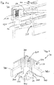
- these ventilation ducts BK in accordance with the exemplary embodiment FIG. 4 are formed by linear grooves extending from the free end of the first portion 32 to the second portion 34. Similarly, webs are formed between the grooves.
- the air thus flows along the ventilation channels BK between the cap portion 32 and the frame 12 from bottom to top in a Free space F, which is formed by the profiling on the second section 34.
- This part of the profiling is realized by two thickened (inwardly projecting) webs / zones 34Z projecting from the inside 34I of the section 34, downwards in the working position towards the bottom 10 of the collector.
- the zone 34Z of the ventilation cap rests on the upper end face 12S of the frame.
- the air sucked in via the ventilation ducts BK can flow around the upper end face 12S of the collector frame 12 into the space F, which as it were continues the ventilation duct BK.
- FIG. 3 It can be seen that the ventilation duct BK merges into an opening 24 which is formed in the corner region E2 by two profiled rails 18. This results in a fluidic connection of the ventilation duct BK in the space R between the glass panes 14, 16th
- a seal 26 On the second glass pane 16 is a seal 26 which engages around a lower end of the spacer 18, which has a T-shape in section.
- the horizontal (upper) T-leg has at one end a bend 18K, which fits positively into a guide groove 12F formed in the frame profile 12, on the inside of a double-walled upper portion 12E.
- the first glass sheet 14 is located, wherein the edge of the glass sheet 14 is surrounded by a seal 28.
- FIG. 1 shows the double-walled upper end 12E of the frame 12 to form a hollow chamber 12H and a screw 12K, in which an L-shaped bar 40 can be screwed (screw 42), which covers the upper glass pane 14 edge and fixed.
- FIG. 1 a fastening screw S is shown schematically.
- the strip 40 is aligned with the vent cap 30.
- a vent cap 30 is disposed in each of the four corner regions of the collector.
- the supports 12L are analogous to the spacers 18 in the corner at a distance from each other ( Fig. 2a ), whereby in each case an opening 25 is formed, so that the air flowing through the ventilation channels BK in the collector space KR, can also penetrate into lower portions of the collector KR and is removed in an analogous manner from the collector space KR.
- FIG. 2 shows openings 42 in the region of the inner wall of the frame 12 at the point at which the frame 12 is formed as a hollow body 12H, wherein this Openings 42 serve to remove any moisture from the collector space KR.
- Fig. 5 is an overall view of a solar thermal collector consisting of 3 sections A1, A1 and A3. Each of these sections A1, A2, A3 is constructed analogously to the features mentioned above.
- the section A1 is formed by four frame sections W1, W2, W3 and W4, which share the section A1 together with an in Fig. 5 unrecognizable bottom and the upper glass pane 14 circumferentially define.
- the special feature of this collector is that the wall W4 simultaneously forms the wall W2 of the adjacent section A2, that is, the wall W4 of A1 or W2 of A2 form a common central web of the overall collector according to FIG. 5 , Correspondingly, for example, the screw channels 12K, arms 12B and guide grooves 12F are formed on both sides of the central web in order to receive the corresponding components such as glass panes, absorbers, etc. on both sides of this frame part. Overall, the overall construction is thereby narrower and structurally easier.
Landscapes
- Engineering & Computer Science (AREA)
- Physics & Mathematics (AREA)
- Life Sciences & Earth Sciences (AREA)
- Sustainable Development (AREA)
- Sustainable Energy (AREA)
- Thermal Sciences (AREA)
- Chemical & Material Sciences (AREA)
- Combustion & Propulsion (AREA)
- Mechanical Engineering (AREA)
- General Engineering & Computer Science (AREA)
- Securing Of Glass Panes Or The Like (AREA)
- Photovoltaic Devices (AREA)
Priority Applications (6)
| Application Number | Priority Date | Filing Date | Title |
|---|---|---|---|
| ES15156910.0T ES2622730T3 (es) | 2015-02-27 | 2015-02-27 | Colector solar |
| EP15156910.0A EP3062035B1 (de) | 2015-02-27 | 2015-02-27 | Solarkollektor |
| PL15156910T PL3062035T3 (pl) | 2015-02-27 | 2015-02-27 | Kolektor słoneczny |
| DK15156910.0T DK3062035T3 (en) | 2015-02-27 | 2015-02-27 | collector |
| PT151569100T PT3062035T (pt) | 2015-02-27 | 2015-02-27 | Colector solar |
| US15/040,620 US10302332B2 (en) | 2015-02-27 | 2016-02-10 | Solar collector |
Applications Claiming Priority (1)
| Application Number | Priority Date | Filing Date | Title |
|---|---|---|---|
| EP15156910.0A EP3062035B1 (de) | 2015-02-27 | 2015-02-27 | Solarkollektor |
Publications (2)
| Publication Number | Publication Date |
|---|---|
| EP3062035A1 EP3062035A1 (de) | 2016-08-31 |
| EP3062035B1 true EP3062035B1 (de) | 2017-02-15 |
Family
ID=52595141
Family Applications (1)
| Application Number | Title | Priority Date | Filing Date |
|---|---|---|---|
| EP15156910.0A Active EP3062035B1 (de) | 2015-02-27 | 2015-02-27 | Solarkollektor |
Country Status (6)
| Country | Link |
|---|---|
| US (1) | US10302332B2 (pl) |
| EP (1) | EP3062035B1 (pl) |
| DK (1) | DK3062035T3 (pl) |
| ES (1) | ES2622730T3 (pl) |
| PL (1) | PL3062035T3 (pl) |
| PT (1) | PT3062035T (pl) |
Families Citing this family (2)
| Publication number | Priority date | Publication date | Assignee | Title |
|---|---|---|---|---|
| US20210317996A1 (en) * | 2018-07-31 | 2021-10-14 | Dale P. Schneider | Solar space heating collector |
| CN119098824A (zh) * | 2023-06-08 | 2024-12-10 | 青岛经济技术开发区海尔热水器有限公司 | 平板集热器中透明盖板的打磨方法及平板集热器 |
Family Cites Families (69)
| Publication number | Priority date | Publication date | Assignee | Title |
|---|---|---|---|---|
| US2684266A (en) * | 1952-03-28 | 1954-07-20 | Pittsburgh Plate Glass Co | Spacer device for multiple glazed units |
| US4003363A (en) * | 1974-06-10 | 1977-01-18 | Abraham Grossman | Solar panel construction |
| US3990429A (en) * | 1975-02-18 | 1976-11-09 | Ppg Industries, Inc. | Solar heat collector having a breather tube |
| US3995613A (en) * | 1975-02-18 | 1976-12-07 | Ppg Industries, Inc. | Solar heat collector unit |
| US3999536A (en) * | 1975-03-19 | 1976-12-28 | Ppg Industries, Inc. | Solar energy absorber plate having a breather tube |
| US3995804A (en) * | 1975-08-15 | 1976-12-07 | Larry J. Folds | Inverted open channel solar heat collector panel |
| US4067317A (en) * | 1976-06-18 | 1978-01-10 | Kawneer Company, Inc. | Solar energy collector panel |
| US4043317A (en) * | 1976-07-02 | 1977-08-23 | Raytheon Company | Vented solar collector |
| US4098259A (en) * | 1976-07-09 | 1978-07-04 | Sunworks, Inc. | Solar energy collection system |
| US4046134A (en) * | 1976-08-26 | 1977-09-06 | Xonics, Inc. | Solar heater with automatic venting |
| US4123883A (en) * | 1977-02-28 | 1978-11-07 | Sunworks, Inc. | Solar energy collector |
| US4132217A (en) * | 1977-05-27 | 1979-01-02 | Solar Energy Products Company | Solar air heat collector |
| US4226225A (en) * | 1977-10-27 | 1980-10-07 | Niedermeyer William P | Thermal overload release for solar energy collectors |
| US4231204A (en) * | 1978-03-31 | 1980-11-04 | Libbey-Owens-Ford Company | Solar energy collector |
| US4278070A (en) * | 1978-08-21 | 1981-07-14 | Ametek, Inc. | Solar energy collector assembly and sub-assemblies thereof |
| US4219009A (en) * | 1978-08-21 | 1980-08-26 | Palmer David W | Vented solar panel |
| US4341200A (en) * | 1978-08-21 | 1982-07-27 | Ametek, Inc. | Solar energy collector sub-assemblies and combinations thereof |
| US4242386A (en) * | 1978-11-28 | 1980-12-30 | Christel Konrad | Multiple glazing units |
| US4242389A (en) | 1979-04-10 | 1980-12-30 | World Carpets, Inc. | Carpet web having patterned adhesive segments on the backing thereof and method of manufacture of the same |
| US4267706A (en) * | 1979-05-31 | 1981-05-19 | Tyler Refrigeration Corporation | Shop around refrigerated merchandiser |
| US4382436A (en) * | 1981-03-24 | 1983-05-10 | Hager I Vincent | Solar window |
| US4351230A (en) * | 1981-04-20 | 1982-09-28 | Sea-Land Service, Inc. | Self-venting cargo container |
| US4503840A (en) * | 1981-07-30 | 1985-03-12 | Burton Energy And Solar Technology Inc. | Solar energy and venting systems |
| US4498458A (en) * | 1981-09-23 | 1985-02-12 | Soper Louis H | Solar heating panel |
| US4397305A (en) * | 1981-10-14 | 1983-08-09 | Solaroi, Inc. | Solar heating panel |
| JPS58198644A (ja) * | 1982-05-14 | 1983-11-18 | Furukawa Electric Co Ltd:The | 平板型太陽熱集熱器 |
| US4478366A (en) * | 1983-07-14 | 1984-10-23 | Coddens Donald L | Ventilation system for reducing the humidity in an attic or roof cavity space |
| US4569330A (en) * | 1984-09-10 | 1986-02-11 | Birger Pettersson | Solar-energy collector that is protected against corrosion |
| US4690128A (en) * | 1986-09-08 | 1987-09-01 | Gibbons Carl B | Insulated flexible bladder solar collector |
| US5353601A (en) * | 1993-02-16 | 1994-10-11 | Palmer Gerald R | Structural cooling systems and methods |
| US5561952A (en) * | 1994-04-11 | 1996-10-08 | Tapco International Corporation | Combination skylight/static ventilator |
| US5561953A (en) * | 1994-12-01 | 1996-10-08 | Rotter; Martin J. | Contoured ventilation system for metal roofs |
| US5653222A (en) * | 1996-01-25 | 1997-08-05 | Newman; Michael D. | Flat plate solar collector |
| JPH11325610A (ja) * | 1998-05-12 | 1999-11-26 | Mitsubishi Electric Corp | 太陽エネルギー利用装置 |
| DE19954238A1 (de) * | 1999-03-16 | 2000-09-28 | Ufe Solar Gmbh | Solarkollektor, bestehend aus einem belüftbaren Gehäuse |
| US6763826B1 (en) * | 2000-04-17 | 2004-07-20 | Robert Gumm | Solar water heater |
| DE10216625B4 (de) * | 2002-04-15 | 2006-02-09 | U.F.E. Solar-Vertriebsgesellschaft Mbh | Befestigungsvorrichtung für eine abdichtende Halterung eines Flächenkörpers |
| US6814070B2 (en) * | 2003-01-06 | 2004-11-09 | Davis Energy Group, Inc. | Molded polymer solar water heater |
| US6695692B1 (en) * | 2003-01-20 | 2004-02-24 | Ronald V York | Curb mount skylight and solar fan combination unit |
| CA2512754C (en) * | 2003-02-07 | 2011-06-28 | Queen's University At Kingston | Method and apparatus for solar collector with integral stagnation temperature control |
| WO2004090439A1 (en) * | 2003-04-11 | 2004-10-21 | Rheem Australia Pty Limited | A protection system for a solar water heating system |
| DE102006061284A1 (de) * | 2006-12-22 | 2008-06-26 | Solarwatt Ag | Plattenförmiges photovoltaisches Solarmodul mit Rahmen aus Formprofilen |
| US20100095610A1 (en) * | 2007-02-21 | 2010-04-22 | Carrier Corporation | Venting Apparatus and Methods |
| US20110277386A1 (en) * | 2007-06-12 | 2011-11-17 | Nevins Robert L | Tri-vent awning window |
| WO2009012190A1 (en) * | 2007-07-15 | 2009-01-22 | Yin Wang | Wood-drying solar greenhouse |
| US20090231807A1 (en) * | 2008-03-13 | 2009-09-17 | Bouissiere Michael F | Waterproof Ventilated Display Enclosure |
| GB2460104B (en) * | 2008-05-16 | 2011-07-27 | Univ Sheffield Hallam | Building ventilator |
| CN101554334B (zh) * | 2009-05-08 | 2011-03-23 | 周晓辉 | 主动性液压心室贴附支持系统 |
| US9266405B1 (en) * | 2009-07-23 | 2016-02-23 | Stephen R. Blanchard | Roof top automobile ventilation system |
| US9773933B2 (en) * | 2010-02-23 | 2017-09-26 | Tenksolar, Inc. | Space and energy efficient photovoltaic array |
| US8281522B1 (en) * | 2010-09-21 | 2012-10-09 | Andrei Hawryshko | Ventilated roofing system |
| EP2437002A1 (en) * | 2010-10-01 | 2012-04-04 | Sunstrip AB | Solar panel ventilation arrangement |
| US9163846B2 (en) * | 2011-01-17 | 2015-10-20 | Vkr Holding A/S | Ventilation apparatus arrangements |
| AT511120B1 (de) * | 2011-02-16 | 2012-12-15 | Aschauer Johann Dipl Ing Mag | Baukonstruktion mit hinterlüfteten fassadenelementen |
| US20120264362A1 (en) * | 2011-04-18 | 2012-10-18 | Samsung Sdi Co., Ltd. | Fuel cell and case for fuel cell |
| US20130027849A1 (en) * | 2011-07-28 | 2013-01-31 | King Abdullah University Of Science And Technology | Pressurized waterproof case for electronic device |
| US9157239B2 (en) * | 2011-09-22 | 2015-10-13 | Digital Control Systems, Inc. | Roof ridge ventilation system |
| US20130149107A1 (en) * | 2011-12-08 | 2013-06-13 | Mrinal Munshi | Gas turbine outer case active ambient cooling including air exhaust into a sub-ambient region of exhaust flow |
| CA2766888C (en) * | 2012-02-03 | 2018-05-08 | Canplas Industries Ltd. | Precipitation control system |
| US8561573B2 (en) * | 2012-03-21 | 2013-10-22 | Dean Michael Bell | Litter box odor device |
| US20140001932A1 (en) * | 2012-06-29 | 2014-01-02 | Nathan L. Westby | Modular Outdoor Enclosure and Gravity Damper System |
| US9496822B2 (en) * | 2012-09-24 | 2016-11-15 | Lockheed Martin Corporation | Hurricane proof solar tracker |
| CN102903772B (zh) * | 2012-09-26 | 2015-09-30 | 友达光电股份有限公司 | 太阳能设备及其组装系统 |
| CN104838217B (zh) * | 2012-10-02 | 2018-05-15 | G·库尔特 | 太阳能空气加热/降温系统 |
| US9263985B2 (en) * | 2012-11-13 | 2016-02-16 | Pi Solar Technology Gmbh | Rooftop photovoltaic modules |
| US9340963B2 (en) * | 2013-02-05 | 2016-05-17 | Bertram Y. ITO | Transportable restroom |
| US10502435B2 (en) * | 2013-09-06 | 2019-12-10 | Zinniatek Limited | Solar thermal roofing system |
| US10221612B2 (en) * | 2014-02-04 | 2019-03-05 | View, Inc. | Infill electrochromic windows |
| US9410325B2 (en) * | 2014-05-06 | 2016-08-09 | Integrated Solar Technology, LLC | Advanced frame design for roof-integrated solar panels |
-
2015
- 2015-02-27 DK DK15156910.0T patent/DK3062035T3/en active
- 2015-02-27 EP EP15156910.0A patent/EP3062035B1/de active Active
- 2015-02-27 PL PL15156910T patent/PL3062035T3/pl unknown
- 2015-02-27 PT PT151569100T patent/PT3062035T/pt unknown
- 2015-02-27 ES ES15156910.0T patent/ES2622730T3/es active Active
-
2016
- 2016-02-10 US US15/040,620 patent/US10302332B2/en active Active
Non-Patent Citations (1)
| Title |
|---|
| None * |
Also Published As
| Publication number | Publication date |
|---|---|
| EP3062035A1 (de) | 2016-08-31 |
| US10302332B2 (en) | 2019-05-28 |
| ES2622730T3 (es) | 2017-07-07 |
| US20160252273A1 (en) | 2016-09-01 |
| PL3062035T3 (pl) | 2017-10-31 |
| PT3062035T (pt) | 2017-04-26 |
| DK3062035T3 (en) | 2017-04-10 |
Similar Documents
| Publication | Publication Date | Title |
|---|---|---|
| DE69219352T2 (de) | Isolierprofil und verfahren für einfache und mehrfache atmosphärisch isolierende baueinheiten | |
| WO2011088994A2 (de) | Randverbundklammer für isolierglaseinheit, randverbund einer isolierglaseinheit, isolierglaseinheit mit randverbundklammer und abstandshalter für isolierglaseinheit | |
| EP0083030A1 (de) | Verfahren zur Herstellung einer gasdicht verschlossenen Hohlkammerplatte aus Kunststoff | |
| DE2951362A1 (de) | Plattenfoermiger sonnenkollektor | |
| DE2649472A1 (de) | Lichtdurchlaessige waermedaemmung | |
| DE3027996A1 (de) | Sonnenkollektor | |
| EP2320020B1 (de) | Abstandhalterrohr für eine Isolierverglasung, sowie Vorrichtung und Verfahren zur Herstellung des Abstandhalterrohrs und Isolierverglasung mit einem aus derartigen Abstandhalterrohren zusammengesetzten Abstandhalterrahmen | |
| EP3062035A1 (de) | Solarkollektor | |
| DE202011050015U1 (de) | Solarkollektor | |
| DE19932830C2 (de) | Lamellenfenster für im wesentlichen senkrechte Fassaden | |
| EP1306627A2 (de) | Vorrichtung zur Nutzung von Sonnenenergie | |
| DE202021103997U1 (de) | Zweischaliges Fassadenelement | |
| DE102021105839A1 (de) | Fassadenkonstruktion | |
| CH706006A2 (de) | Rahmenprofil für Photovoltaikzelle. | |
| DE19733075C1 (de) | Dämmsystem für Gebäudefassaden | |
| DE2725633A1 (de) | Flaechiger sonnenenergiesammler mit geringem waermekontakt zwischen absorber und rand des sammlers | |
| DE3309252A1 (de) | Sonnenkollektor | |
| DE2746607B1 (de) | Abstandhalter fuer Mehrscheiben-Isolierglas,bestehend aus einem zu einem Rahmen geformten Hohlprofil | |
| EP3530860B1 (de) | Isolierglaselement für eine glasfassade und glasfassade | |
| DE10204585B4 (de) | Sonnenkollektor zum vorzugsweisen Betrieb mit gasförmigen Medien | |
| EP3186457B1 (de) | Gebäudehüllenflächenelement, verbundfenster und gebäudefassadensystem | |
| EP3152372B1 (de) | Tragkonstruktion zur anordnung von paneelen | |
| AT231136B (de) | Doppelglasscheibe | |
| EP3626900B1 (de) | Dämmelement für eine fassaden-, fenster- oder türkonstruktion und fassadenkonstruktion mit einem derartigen dämmelement | |
| EP0709540A2 (de) | Brandsichere Halterung mindestens einer Scheibe |
Legal Events
| Date | Code | Title | Description |
|---|---|---|---|
| PUAI | Public reference made under article 153(3) epc to a published international application that has entered the european phase |
Free format text: ORIGINAL CODE: 0009012 |
|
| 17P | Request for examination filed |
Effective date: 20151222 |
|
| AK | Designated contracting states |
Kind code of ref document: A1 Designated state(s): AL AT BE BG CH CY CZ DE DK EE ES FI FR GB GR HR HU IE IS IT LI LT LU LV MC MK MT NL NO PL PT RO RS SE SI SK SM TR |
|
| AX | Request for extension of the european patent |
Extension state: BA ME |
|
| GRAP | Despatch of communication of intention to grant a patent |
Free format text: ORIGINAL CODE: EPIDOSNIGR1 |
|
| INTG | Intention to grant announced |
Effective date: 20161024 |
|
| STAA | Information on the status of an ep patent application or granted ep patent |
Free format text: STATUS: GRANT OF PATENT IS INTENDED |
|
| GRAS | Grant fee paid |
Free format text: ORIGINAL CODE: EPIDOSNIGR3 |
|
| GRAA | (expected) grant |
Free format text: ORIGINAL CODE: 0009210 |
|
| STAA | Information on the status of an ep patent application or granted ep patent |
Free format text: STATUS: THE PATENT HAS BEEN GRANTED |
|
| AK | Designated contracting states |
Kind code of ref document: B1 Designated state(s): AL AT BE BG CH CY CZ DE DK EE ES FI FR GB GR HR HU IE IS IT LI LT LU LV MC MK MT NL NO PL PT RO RS SE SI SK SM TR |
|
| REG | Reference to a national code |
Ref country code: CH Ref legal event code: EP Ref country code: GB Ref legal event code: FG4D Free format text: NOT ENGLISH |
|
| REG | Reference to a national code |
Ref country code: IE Ref legal event code: FG4D Free format text: LANGUAGE OF EP DOCUMENT: GERMAN |
|
| REG | Reference to a national code |
Ref country code: AT Ref legal event code: REF Ref document number: 868144 Country of ref document: AT Kind code of ref document: T Effective date: 20170315 |
|
| REG | Reference to a national code |
Ref country code: DE Ref legal event code: R096 Ref document number: 502015000578 Country of ref document: DE Ref country code: FR Ref legal event code: PLFP Year of fee payment: 3 |
|
| REG | Reference to a national code |
Ref country code: DK Ref legal event code: T3 Effective date: 20170404 |
|
| REG | Reference to a national code |
Ref country code: PT Ref legal event code: SC4A Ref document number: 3062035 Country of ref document: PT Date of ref document: 20170426 Kind code of ref document: T Free format text: AVAILABILITY OF NATIONAL TRANSLATION Effective date: 20170418 |
|
| REG | Reference to a national code |
Ref country code: NL Ref legal event code: MP Effective date: 20170215 |
|
| REG | Reference to a national code |
Ref country code: LT Ref legal event code: MG4D |
|
| REG | Reference to a national code |
Ref country code: ES Ref legal event code: FG2A Ref document number: 2622730 Country of ref document: ES Kind code of ref document: T3 Effective date: 20170707 |
|
| PG25 | Lapsed in a contracting state [announced via postgrant information from national office to epo] |
Ref country code: LT Free format text: LAPSE BECAUSE OF FAILURE TO SUBMIT A TRANSLATION OF THE DESCRIPTION OR TO PAY THE FEE WITHIN THE PRESCRIBED TIME-LIMIT Effective date: 20170215 Ref country code: NO Free format text: LAPSE BECAUSE OF FAILURE TO SUBMIT A TRANSLATION OF THE DESCRIPTION OR TO PAY THE FEE WITHIN THE PRESCRIBED TIME-LIMIT Effective date: 20170515 Ref country code: HR Free format text: LAPSE BECAUSE OF FAILURE TO SUBMIT A TRANSLATION OF THE DESCRIPTION OR TO PAY THE FEE WITHIN THE PRESCRIBED TIME-LIMIT Effective date: 20170215 Ref country code: FI Free format text: LAPSE BECAUSE OF FAILURE TO SUBMIT A TRANSLATION OF THE DESCRIPTION OR TO PAY THE FEE WITHIN THE PRESCRIBED TIME-LIMIT Effective date: 20170215 |
|
| PG25 | Lapsed in a contracting state [announced via postgrant information from national office to epo] |
Ref country code: BG Free format text: LAPSE BECAUSE OF FAILURE TO SUBMIT A TRANSLATION OF THE DESCRIPTION OR TO PAY THE FEE WITHIN THE PRESCRIBED TIME-LIMIT Effective date: 20170515 Ref country code: RS Free format text: LAPSE BECAUSE OF FAILURE TO SUBMIT A TRANSLATION OF THE DESCRIPTION OR TO PAY THE FEE WITHIN THE PRESCRIBED TIME-LIMIT Effective date: 20170215 Ref country code: NL Free format text: LAPSE BECAUSE OF NON-PAYMENT OF DUE FEES Effective date: 20170215 Ref country code: LV Free format text: LAPSE BECAUSE OF FAILURE TO SUBMIT A TRANSLATION OF THE DESCRIPTION OR TO PAY THE FEE WITHIN THE PRESCRIBED TIME-LIMIT Effective date: 20170215 Ref country code: SE Free format text: LAPSE BECAUSE OF FAILURE TO SUBMIT A TRANSLATION OF THE DESCRIPTION OR TO PAY THE FEE WITHIN THE PRESCRIBED TIME-LIMIT Effective date: 20170215 |
|
| PG25 | Lapsed in a contracting state [announced via postgrant information from national office to epo] |
Ref country code: EE Free format text: LAPSE BECAUSE OF FAILURE TO SUBMIT A TRANSLATION OF THE DESCRIPTION OR TO PAY THE FEE WITHIN THE PRESCRIBED TIME-LIMIT Effective date: 20170215 Ref country code: SK Free format text: LAPSE BECAUSE OF FAILURE TO SUBMIT A TRANSLATION OF THE DESCRIPTION OR TO PAY THE FEE WITHIN THE PRESCRIBED TIME-LIMIT Effective date: 20170215 Ref country code: CZ Free format text: LAPSE BECAUSE OF FAILURE TO SUBMIT A TRANSLATION OF THE DESCRIPTION OR TO PAY THE FEE WITHIN THE PRESCRIBED TIME-LIMIT Effective date: 20170215 Ref country code: RO Free format text: LAPSE BECAUSE OF FAILURE TO SUBMIT A TRANSLATION OF THE DESCRIPTION OR TO PAY THE FEE WITHIN THE PRESCRIBED TIME-LIMIT Effective date: 20170215 |
|
| REG | Reference to a national code |
Ref country code: DE Ref legal event code: R097 Ref document number: 502015000578 Country of ref document: DE |
|
| REG | Reference to a national code |
Ref country code: GR Ref legal event code: EP Ref document number: 20170401222 Country of ref document: GR Effective date: 20171122 |
|
| REG | Reference to a national code |
Ref country code: DE Ref legal event code: R079 Ref document number: 502015000578 Country of ref document: DE Free format text: PREVIOUS MAIN CLASS: F24J0002460000 Ipc: F24S0040000000 |
|
| REG | Reference to a national code |
Ref country code: IE Ref legal event code: MM4A |
|
| PG25 | Lapsed in a contracting state [announced via postgrant information from national office to epo] |
Ref country code: MC Free format text: LAPSE BECAUSE OF FAILURE TO SUBMIT A TRANSLATION OF THE DESCRIPTION OR TO PAY THE FEE WITHIN THE PRESCRIBED TIME-LIMIT Effective date: 20170215 Ref country code: SM Free format text: LAPSE BECAUSE OF FAILURE TO SUBMIT A TRANSLATION OF THE DESCRIPTION OR TO PAY THE FEE WITHIN THE PRESCRIBED TIME-LIMIT Effective date: 20170215 |
|
| PLBE | No opposition filed within time limit |
Free format text: ORIGINAL CODE: 0009261 |
|
| STAA | Information on the status of an ep patent application or granted ep patent |
Free format text: STATUS: NO OPPOSITION FILED WITHIN TIME LIMIT |
|
| PG25 | Lapsed in a contracting state [announced via postgrant information from national office to epo] |
Ref country code: LU Free format text: LAPSE BECAUSE OF NON-PAYMENT OF DUE FEES Effective date: 20170227 |
|
| 26N | No opposition filed |
Effective date: 20171116 |
|
| REG | Reference to a national code |
Ref country code: BE Ref legal event code: MM Effective date: 20170228 |
|
| REG | Reference to a national code |
Ref country code: FR Ref legal event code: PLFP Year of fee payment: 4 |
|
| PG25 | Lapsed in a contracting state [announced via postgrant information from national office to epo] |
Ref country code: SI Free format text: LAPSE BECAUSE OF FAILURE TO SUBMIT A TRANSLATION OF THE DESCRIPTION OR TO PAY THE FEE WITHIN THE PRESCRIBED TIME-LIMIT Effective date: 20170215 Ref country code: IE Free format text: LAPSE BECAUSE OF NON-PAYMENT OF DUE FEES Effective date: 20170227 |
|
| PG25 | Lapsed in a contracting state [announced via postgrant information from national office to epo] |
Ref country code: BE Free format text: LAPSE BECAUSE OF NON-PAYMENT OF DUE FEES Effective date: 20170228 |
|
| PG25 | Lapsed in a contracting state [announced via postgrant information from national office to epo] |
Ref country code: MT Free format text: LAPSE BECAUSE OF FAILURE TO SUBMIT A TRANSLATION OF THE DESCRIPTION OR TO PAY THE FEE WITHIN THE PRESCRIBED TIME-LIMIT Effective date: 20170215 |
|
| PG25 | Lapsed in a contracting state [announced via postgrant information from national office to epo] |
Ref country code: HU Free format text: LAPSE BECAUSE OF FAILURE TO SUBMIT A TRANSLATION OF THE DESCRIPTION OR TO PAY THE FEE WITHIN THE PRESCRIBED TIME-LIMIT; INVALID AB INITIO Effective date: 20150227 |
|
| PG25 | Lapsed in a contracting state [announced via postgrant information from national office to epo] |
Ref country code: CY Free format text: LAPSE BECAUSE OF FAILURE TO SUBMIT A TRANSLATION OF THE DESCRIPTION OR TO PAY THE FEE WITHIN THE PRESCRIBED TIME-LIMIT Effective date: 20170215 |
|
| PG25 | Lapsed in a contracting state [announced via postgrant information from national office to epo] |
Ref country code: MK Free format text: LAPSE BECAUSE OF FAILURE TO SUBMIT A TRANSLATION OF THE DESCRIPTION OR TO PAY THE FEE WITHIN THE PRESCRIBED TIME-LIMIT Effective date: 20170215 |
|
| PG25 | Lapsed in a contracting state [announced via postgrant information from national office to epo] |
Ref country code: TR Free format text: LAPSE BECAUSE OF FAILURE TO SUBMIT A TRANSLATION OF THE DESCRIPTION OR TO PAY THE FEE WITHIN THE PRESCRIBED TIME-LIMIT Effective date: 20170215 |
|
| PG25 | Lapsed in a contracting state [announced via postgrant information from national office to epo] |
Ref country code: AL Free format text: LAPSE BECAUSE OF FAILURE TO SUBMIT A TRANSLATION OF THE DESCRIPTION OR TO PAY THE FEE WITHIN THE PRESCRIBED TIME-LIMIT Effective date: 20170215 Ref country code: IS Free format text: LAPSE BECAUSE OF FAILURE TO SUBMIT A TRANSLATION OF THE DESCRIPTION OR TO PAY THE FEE WITHIN THE PRESCRIBED TIME-LIMIT Effective date: 20170615 |
|
| PGFP | Annual fee paid to national office [announced via postgrant information from national office to epo] |
Ref country code: PT Payment date: 20250218 Year of fee payment: 11 Ref country code: DE Payment date: 20250218 Year of fee payment: 11 |
|
| PGFP | Annual fee paid to national office [announced via postgrant information from national office to epo] |
Ref country code: DK Payment date: 20250219 Year of fee payment: 11 |
|
| PGFP | Annual fee paid to national office [announced via postgrant information from national office to epo] |
Ref country code: ES Payment date: 20250318 Year of fee payment: 11 |
|
| PGFP | Annual fee paid to national office [announced via postgrant information from national office to epo] |
Ref country code: CH Payment date: 20250301 Year of fee payment: 11 Ref country code: GR Payment date: 20250217 Year of fee payment: 11 Ref country code: AT Payment date: 20250217 Year of fee payment: 11 |
|
| PGFP | Annual fee paid to national office [announced via postgrant information from national office to epo] |
Ref country code: FR Payment date: 20250220 Year of fee payment: 11 Ref country code: PL Payment date: 20250218 Year of fee payment: 11 |
|
| PGFP | Annual fee paid to national office [announced via postgrant information from national office to epo] |
Ref country code: IT Payment date: 20250228 Year of fee payment: 11 Ref country code: GB Payment date: 20250220 Year of fee payment: 11 |