EP3059854B1 - Variable-speed operation control apparatus and hydroelectric power generation system - Google Patents
Variable-speed operation control apparatus and hydroelectric power generation system Download PDFInfo
- Publication number
- EP3059854B1 EP3059854B1 EP16156134.5A EP16156134A EP3059854B1 EP 3059854 B1 EP3059854 B1 EP 3059854B1 EP 16156134 A EP16156134 A EP 16156134A EP 3059854 B1 EP3059854 B1 EP 3059854B1
- Authority
- EP
- European Patent Office
- Prior art keywords
- power generator
- power
- branch circuit
- flow rate
- variable
- Prior art date
- Legal status (The legal status is an assumption and is not a legal conclusion. Google has not performed a legal analysis and makes no representation as to the accuracy of the status listed.)
- Active
Links
Images
Classifications
-
- H—ELECTRICITY
- H02—GENERATION; CONVERSION OR DISTRIBUTION OF ELECTRIC POWER
- H02P—CONTROL OR REGULATION OF ELECTRIC MOTORS, ELECTRIC GENERATORS OR DYNAMO-ELECTRIC CONVERTERS; CONTROLLING TRANSFORMERS, REACTORS OR CHOKE COILS
- H02P9/00—Arrangements for controlling electric generators for the purpose of obtaining a desired output
- H02P9/48—Arrangements for obtaining a constant output value at varying speed of the generator, e.g. on vehicle
-
- F—MECHANICAL ENGINEERING; LIGHTING; HEATING; WEAPONS; BLASTING
- F03—MACHINES OR ENGINES FOR LIQUIDS; WIND, SPRING, OR WEIGHT MOTORS; PRODUCING MECHANICAL POWER OR A REACTIVE PROPULSIVE THRUST, NOT OTHERWISE PROVIDED FOR
- F03B—MACHINES OR ENGINES FOR LIQUIDS
- F03B13/00—Adaptations of machines or engines for special use; Combinations of machines or engines with driving or driven apparatus; Power stations or aggregates
- F03B13/08—Machine or engine aggregates in dams or the like; Conduits therefor, e.g. diffusors
-
- F—MECHANICAL ENGINEERING; LIGHTING; HEATING; WEAPONS; BLASTING
- F03—MACHINES OR ENGINES FOR LIQUIDS; WIND, SPRING, OR WEIGHT MOTORS; PRODUCING MECHANICAL POWER OR A REACTIVE PROPULSIVE THRUST, NOT OTHERWISE PROVIDED FOR
- F03B—MACHINES OR ENGINES FOR LIQUIDS
- F03B15/00—Controlling
-
- H—ELECTRICITY
- H02—GENERATION; CONVERSION OR DISTRIBUTION OF ELECTRIC POWER
- H02J—CIRCUIT ARRANGEMENTS OR SYSTEMS FOR SUPPLYING OR DISTRIBUTING ELECTRIC POWER; SYSTEMS FOR STORING ELECTRIC ENERGY
- H02J3/00—Circuit arrangements for AC mains or AC distribution networks
- H02J3/38—Arrangements for parallely feeding a single network by two or more generators, converters or transformers
-
- H—ELECTRICITY
- H02—GENERATION; CONVERSION OR DISTRIBUTION OF ELECTRIC POWER
- H02K—DYNAMO-ELECTRIC MACHINES
- H02K7/00—Arrangements for handling mechanical energy structurally associated with dynamo-electric machines, e.g. structural association with mechanical driving motors or auxiliary dynamo-electric machines
- H02K7/18—Structural association of electric generators with mechanical driving motors, e.g. with turbines
- H02K7/1807—Rotary generators
- H02K7/1823—Rotary generators structurally associated with turbines or similar engines
-
- H—ELECTRICITY
- H02—GENERATION; CONVERSION OR DISTRIBUTION OF ELECTRIC POWER
- H02P—CONTROL OR REGULATION OF ELECTRIC MOTORS, ELECTRIC GENERATORS OR DYNAMO-ELECTRIC CONVERTERS; CONTROLLING TRANSFORMERS, REACTORS OR CHOKE COILS
- H02P1/00—Arrangements for starting electric motors or dynamo-electric converters
- H02P1/16—Arrangements for starting electric motors or dynamo-electric converters for starting dynamo-electric motors or dynamo-electric converters
- H02P1/46—Arrangements for starting electric motors or dynamo-electric converters for starting dynamo-electric motors or dynamo-electric converters for starting an individual synchronous motor
- H02P1/52—Arrangements for starting electric motors or dynamo-electric converters for starting dynamo-electric motors or dynamo-electric converters for starting an individual synchronous motor by progressive increase of frequency of supply to motor
-
- H—ELECTRICITY
- H02—GENERATION; CONVERSION OR DISTRIBUTION OF ELECTRIC POWER
- H02P—CONTROL OR REGULATION OF ELECTRIC MOTORS, ELECTRIC GENERATORS OR DYNAMO-ELECTRIC CONVERTERS; CONTROLLING TRANSFORMERS, REACTORS OR CHOKE COILS
- H02P27/00—Arrangements or methods for the control of AC motors characterised by the kind of supply voltage
-
- H—ELECTRICITY
- H02—GENERATION; CONVERSION OR DISTRIBUTION OF ELECTRIC POWER
- H02P—CONTROL OR REGULATION OF ELECTRIC MOTORS, ELECTRIC GENERATORS OR DYNAMO-ELECTRIC CONVERTERS; CONTROLLING TRANSFORMERS, REACTORS OR CHOKE COILS
- H02P9/00—Arrangements for controlling electric generators for the purpose of obtaining a desired output
- H02P9/42—Arrangements for controlling electric generators for the purpose of obtaining a desired output to obtain desired frequency without varying speed of the generator
-
- F—MECHANICAL ENGINEERING; LIGHTING; HEATING; WEAPONS; BLASTING
- F05—INDEXING SCHEMES RELATING TO ENGINES OR PUMPS IN VARIOUS SUBCLASSES OF CLASSES F01-F04
- F05B—INDEXING SCHEME RELATING TO WIND, SPRING, WEIGHT, INERTIA OR LIKE MOTORS, TO MACHINES OR ENGINES FOR LIQUIDS COVERED BY SUBCLASSES F03B, F03D AND F03G
- F05B2270/00—Control
- F05B2270/30—Control parameters, e.g. input parameters
- F05B2270/327—Rotor or generator speeds
-
- Y—GENERAL TAGGING OF NEW TECHNOLOGICAL DEVELOPMENTS; GENERAL TAGGING OF CROSS-SECTIONAL TECHNOLOGIES SPANNING OVER SEVERAL SECTIONS OF THE IPC; TECHNICAL SUBJECTS COVERED BY FORMER USPC CROSS-REFERENCE ART COLLECTIONS [XRACs] AND DIGESTS
- Y02—TECHNOLOGIES OR APPLICATIONS FOR MITIGATION OR ADAPTATION AGAINST CLIMATE CHANGE
- Y02E—REDUCTION OF GREENHOUSE GAS [GHG] EMISSIONS, RELATED TO ENERGY GENERATION, TRANSMISSION OR DISTRIBUTION
- Y02E10/00—Energy generation through renewable energy sources
- Y02E10/20—Hydro energy
Definitions
- Embodiments described herein relate generally to a variable-speed operation control apparatus and a hydroelectric power generation system.
- Small-and-medium-sized hydroelectric power plants are generally run-off-river-type plants.
- an output varies depending on a flow rate of a river. If the flow rate of the river drops considerably, a strong swirling flow may be produced and cavitation may occur at a runner outlet of a water turbine. As a result, large vibrations and loud noise may occur in a tube of the plant, and stable operation will be difficult. Therefore, in general, a minimum flow rate which allows the power plant to operate is determined in advance, and when the flow rate drops below the minimum, operation of the power plant facility is stopped.
- an improved arrangement of fins attached to a draft tube of a water turbine is known.
- variable-speed operation control apparatus and a hydroelectric power generation system, in which even when the flow rate of a river or the like is less than a fixed level, a stable operation can be conducted by reducing the rotation speed.
- the invention relates to a variable-speed operation control apparatus of a hydroelectric power generation system including a power generator interconnected to a power system including a main transformer through a main circuit and a water turbine directly connected to the power generator, the variable-speed operation control apparatus comprising: a branch circuit branched from the main circuit and including a frequency converter which performs conversion between an output frequency of the power generator and a system frequency of the power system (P), wherein the frequency converter has a smaller capacity in comparison to the power generator, wherein the main circuit comprises a current transformer and a potential transformer, respectively configured to detect a current and a voltage when the main circuit is used, the branch circuit comprises a current transformer and a potential transformer, respectively configured to detect a current and a voltage when the branch circuit is used, the branch circuit further comprising a second breaker and the main circuit comprises a first breaker, the second breaker is connected between the power generator and the frequency converter, and the first breaker is directly connected between the power generator and the main transformer to pass an output from the power generator to the main transformer
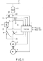
- FIG. 1 is a schematic diagram showing a hydroelectric power generation system according to an embodiment.
- the hydroelectric power generation system shown in FIG. 1 includes a power generator 3 interconnected to a power system P through a main circuit 11 including a breaker 1 and a main transformer 2; and a water turbine 4 directly connected to the power generator 3.
- the hydroelectric power generation system further includes a branch circuit 12, which branches from the main circuit 11 at branch points D1 and D2.
- the branch circuit 12 is a circuit bypassing the breaker 1, and includes a frequency converter 5 which performs conversion between an output frequency of the power generator 3 and a system frequency of the power system P, and a breaker 6 connected in series with the frequency converter 5.
- the branch circuit 12 is a special circuit that is used only for operations other than a normal operation, for example, only in the case where the flow rate is less than the minimum flow rate required for normal operation.
- the frequency converter 5 in the branch circuit 12 has a limited capacity necessary to realize operation in a less-than-minimum flow rate. It has a smaller capacity and size in comparison to the power generator 3.
- the frequency converter 5 is capable of changing a frequency of the power generator 3, such that it can change the rotation speed (or the number of rotations or frequency) of the power generator 3 and the water turbine 4.
- the hydroelectric power generation system further includes a controller 7 which controls operations of the system.
- the controller 7 can change the rotation speed (or the number of rotations or frequency) of the power generator 3 and the water turbine 4 by opening or closing the breakers 1 and 6 in accordance with situations, or by changing the frequency output from the side of the power generator 3 of the frequency converter 5 when the breaker 6 is closed.
- the controller 7 executes a control of changing an interconnection route by operating the breaker 1 and the breaker 6 (switching the breaker 1 from a closed position to an open position and switching the breaker 6 from an open position to a closed position) to interconnect the power generator 3 to the power system P through the branch circuit 12, and a control of operating the frequency converter 5 (gradually lowering the frequency output from the frequency converter 5 on the side of the power generator 3 from the normal frequency (e.g., 50Hz)) to gradually lower the rotation speed of the power generator 3 and the water turbine 4 to a target rotation speed.
- the normal frequency e.g., 50Hz
- the controller 7 When the flow rate returns to a normal state, the controller 7 performs a control of operating the frequency converter 5 (gradually increasing the frequency output from the frequency converter 5 on the side of the power generator 3 toward the normal frequency (e.g., 50Hz)) to increase the rotation speed of the power generator 4 and the water turbine 3 to the normal rotation speed, and a control of changing the interconnection route by operating the breaker 1 and the breaker 6 (switching the breaker 6 from the closed position to the open position and switching the breaker 1 from the open position to the closed position) to interconnect the power generator 3 to the power system P through the branch circuit 11, not through the branch circuit 12.
- the normal frequency e.g. 50Hz
- the example shown in FIG. 1 uses the breaker 6 as switching equipment in the branch circuit 12.
- the breaker 6 may be replaced with another type of switch, for example, a semiconductor switch, which fulfills a function similar to that of the breaker 6.
- a semiconductor switch can realize high-speed performance that cannot be realized by a mechanical switch.
- a current transformer (CT) 31 and a potential transformer (PT) 32 which respectively detect a current and a voltage when the branch circuit 12 is used, are provided between the frequency converter 5 and the branch point D2 of the branch circuit 12. Results of the detection are sent to the controller 7.
- the controller 7 can: obtain a current value and a voltage value detected by the current transformer 21 and the potential transformer 22 in the main circuit 11 and calculate an output of the power generator 3 based on these values; obtain information on a current and a voltage detected by the current transformer 31 and the potential transformer 32 in the branch circuit 12 and calculate a frequency-converted output of the power generator 3 based on these values; obtain information on the flow rate of water (for example, the flow rate of a river or of water flowing to the water turbine 4); and obtain information on a water level (for example, a water level of a dam, etc. of a reservoir, and calculate a drop (for example, a difference in height between a water intake level and a water outflow level) from the water level.
- the obtained information and calculated information are used to determine whether to switch the route interconnecting the power generator 3 to the power system P.
- variable-speed operation control apparatus of this embodiment may be composed of at least the branch circuit 12 and the controller 7 described above.
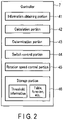
- FIG. 2 is a block diagram showing a functional configuration of the controller 7.
- the controller 7 includes a variety functions: an information obtaining portion 41, a calculation portion 42, a determination portion 43, a switch control portion 44, a rotation speed control portion 45 and a storage portion 46.
- the information obtaining portion 41 has a function of obtaining a current value and a voltage value detected by the current transformer 21 and the potential transformer 22 of the main circuit 11, a current and a voltage detected by the current transformer 31 and the potential transformer 32 of the branch circuit 12, and information on a flow rate and a water level.
- the calculation portion 42 has a function of: obtaining an output of the power generator 3 from the detected current value and voltage value using a table (correspondence table), a function or an arithmetic expression; calculating a drop from the detected water level; and obtaining a rotation speed (or the number of rotations or frequency) of the water turbine 4 and the power generator 3, which will be less liable to cause cavitation, based on the detected flow rate.
- the determination portion 43 has a function of comparing a flow rate, a drop, or an output with a corresponding threshold, and determining whether to switch the interconnection route.
- the switch control portion 44 has a function of controlling switching of the interconnection route in accordance with a result of determination in the determination portion 43.
- the rotation speed control portion 45 has a function of controlling rotation of the water turbine 4 and the power generator 3 at an appropriate rotation speed corresponding to the flow rate by operation of the frequency converter 5.
- the storage portion 46 has a memory function of storing a table (correspondence table), a function, or an arithmetic expression which the calculation portion 42 uses. It stores, for example, a table showing the relationship between a flow rate and an appropriate rotation speed (or the number of rotations or frequency) corresponding to the flow rate. Accordingly, an appropriate rotation speed (or the number of rotations or frequency) corresponding to the flow rate can be derived from, for example, a flow rate less than the minimum.
- the storage portion 46 also stores a table showing the relationship between a drop and an appropriate rotation speed (or the number of rotations or frequency) corresponding to the drop, and a table showing the relationship between an output and an appropriate rotation speed (or the number of rotations or frequency) corresponding to the output.
- the controller 7 selectively performs, for example, the following controls using a variety of functions described above.
- the controller 7 when the controller 7 obtains information indicative of a flow rate and determines that the flow rate is less than a predetermined value, it can perform control of switching the interconnection route to interconnect the power generator 3 with the power system P through the branch circuit 12.
- the controller 7 obtains information indicative of a water level and calculates a drop from the water level. When the drop is smaller than a predetermined value, the controller 7 can perform control of switching the interconnection route to interconnect the power generator 3 with the power system P through the branch circuit 12.
- the controller 7 obtains an output of the power generator 3 by the calculation portion 42 from the obtained voltage and current of the main circuit 11. When the output is smaller than a predetermined value, the controller 7 can perform control of switching the interconnection route to interconnect the power generator 3 with the power system P through the branch circuit 12.
- the controller 7 obtains an output of the power generator 3 in the case of using the branch circuit 12 and an output of the power generator 3 in the case using the main circuit 11 without using the branch circuit 12. When a greater one of these outputs is smaller than a predetermined value, the controller 7 can perform control of switching the interconnection route to interconnect the power generator 3 with the power system P through the branch circuit 12.
- the frequency converter 5 shown in FIG. 1 has a smaller capacity and size in comparison to the power generator 3.
- the capacity of the frequency converter 5 can be further reduced, while ensuring a capacity necessary to realize operation at the less-than-minimum flow rate.
- the reduction of the capacity can be achieved by connecting, for example, a relatively compact transformer in series to both or either side of the frequency converter 5.
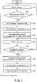
- controller 7 As the controller 7 is monitoring a state of the flow rate, it obtains information on the flow rate of water (for example, the flow rate of a river or of water flowing to the water turbine 4) (step S11). The controller 7 periodically determines whether the flow rate is less than a predetermined value (step S12). If the flow rate is not less than the predetermined value (NO in step S12), the operation returns to step S11 and the processing is repeated.
- a predetermined value for example, the flow rate of a river or of water flowing to the water turbine 4
- the controller 7 operates the breakers 1 and 6, such that the power generator 3 is interconnected to the power system P through the branch circuit 12. Specifically, the breaker 1 is switched from the closed position to the open position (step S13), and thereafter the breaker 6 is switched from the open position to the closed position (step S14). Then, the controller 7 operates the frequency converter 5 to reduce the rotation speed of the power generator 3 and the water turbine 4 to a target rotation speed (step S15). In this case, the controller 7 gradually lowers the frequency output from the frequency converter 5 on the side of the power generator 3 from the normal frequency (e.g., 50Hz) to gradually lower the rotation speed of the power generator 3 and the water turbine 4 to a target rotation speed.
- the normal frequency e.g., 50Hz
- the controller 7 subsequently monitors a state of the flow rate, while obtaining information on the flow rate of water (step S21), and periodically determines whether the flow rate is more than a predetermined value (step S22). If the flow rate is not more than the predetermined value (NO in step S22), the operation returns to step S21 and the processing is repeated.
- the controller 7 operates the frequency converter 5 to gradually increase the rotation speed of the power generator 3 and the water turbine 4 to a normal rotation speed (step S23).
- the controller 7 gradually increases the frequency output from the frequency converter 5 on the side of the power generator 3 toward the normal frequency (e.g., 50Hz) to gradually increase the rotation speed of the power generator 4 and the water turbine 3 to the normal rotation speed (step S23).
- the controller 7 operates the breakers 1 and 6, such that the power generator 3 is interconnected to the power system P through the main circuit 11, not through the branch circuit 12. Specifically, the breaker 6 is switched from the closed position to the open position (step S24), and thereafter the breaker 1 is switched from the open position to the closed position (step S25).
- the apparatus returns to the normal operation state. Thereafter, the operation returns to step S11 and the processing is repeated.
- undesired loss by the frequency converter does not occur during the normal operation. Furthermore, even during operation in a less-than-minimum flow rate, a large loss can be avoided, since a minimum capacity converter is used. Furthermore, stable operation which will be less liable to cause cavitation can be performed.
Landscapes
- Engineering & Computer Science (AREA)
- Power Engineering (AREA)
- Chemical & Material Sciences (AREA)
- Combustion & Propulsion (AREA)
- Mechanical Engineering (AREA)
- General Engineering & Computer Science (AREA)
- Control Of Eletrric Generators (AREA)
Applications Claiming Priority (1)
| Application Number | Priority Date | Filing Date | Title |
|---|---|---|---|
| JP2015033302A JP6246753B2 (ja) | 2015-02-23 | 2015-02-23 | 可変速運転制御装置および水力発電システム |
Publications (2)
| Publication Number | Publication Date |
|---|---|
| EP3059854A1 EP3059854A1 (en) | 2016-08-24 |
| EP3059854B1 true EP3059854B1 (en) | 2022-04-20 |
Family
ID=55745528
Family Applications (1)
| Application Number | Title | Priority Date | Filing Date |
|---|---|---|---|
| EP16156134.5A Active EP3059854B1 (en) | 2015-02-23 | 2016-02-17 | Variable-speed operation control apparatus and hydroelectric power generation system |
Country Status (3)
| Country | Link |
|---|---|
| US (1) | US10425027B2 (enExample) |
| EP (1) | EP3059854B1 (enExample) |
| JP (1) | JP6246753B2 (enExample) |
Families Citing this family (8)
| Publication number | Priority date | Publication date | Assignee | Title |
|---|---|---|---|---|
| CN113381561A (zh) * | 2016-09-20 | 2021-09-10 | 大金工业株式会社 | 水力发电系统 |
| JP7012513B2 (ja) * | 2017-11-13 | 2022-01-28 | 株式会社日立製作所 | 水力発電システム |
| PT3502462T (pt) * | 2017-12-19 | 2021-07-07 | Ge Renewable Tech | Instalação para converter energia hidráulica em energia elétrica com uma máquina hidráulica e um conversor de frequência estática e método correspondente |
| JP6593429B2 (ja) * | 2017-12-20 | 2019-10-23 | ダイキン工業株式会社 | 流体装置 |
| CN112236934B (zh) | 2018-06-07 | 2024-04-19 | 日立三菱水力株式会社 | 可变速发电电动装置 |
| JPWO2020013015A1 (ja) * | 2018-07-09 | 2021-05-20 | 日立三菱水力株式会社 | 可変速発電電動装置 |
| CN109948842B (zh) * | 2019-03-12 | 2022-12-02 | 大连理工大学 | 一种控制水库水位变动频率的水电站长期优化调度方法 |
| JP7365272B2 (ja) | 2020-03-11 | 2023-10-19 | 株式会社日立製作所 | 同期機装置、可変速揚水発電装置、ならびに運転方法 |
Citations (1)
| Publication number | Priority date | Publication date | Assignee | Title |
|---|---|---|---|---|
| FR2561718A1 (fr) * | 1984-02-24 | 1985-09-27 | Neyrpic | Installation hydroelectrique de basse chute |
Family Cites Families (28)
| Publication number | Priority date | Publication date | Assignee | Title |
|---|---|---|---|---|
| DE2258252A1 (de) * | 1972-11-28 | 1974-06-12 | Siemens Ag | Ueberwachungseinrichtung fuer einen luefter |
| US4496845A (en) * | 1982-12-27 | 1985-01-29 | Cla-Val Co. | Method and apparatus for control of a turbine generator |
| US5509434A (en) * | 1994-12-06 | 1996-04-23 | Halliburton Company | Apparatus and method for controlling and metering the flow of gas through a pipeline |
| US6600240B2 (en) * | 1997-08-08 | 2003-07-29 | General Electric Company | Variable speed wind turbine generator |
| JPH11280634A (ja) | 1998-03-27 | 1999-10-15 | Fuji Fuoito Hydro Kk | 水車及びポンプ水車 |
| DE10114075B4 (de) * | 2001-03-22 | 2005-08-18 | Semikron Elektronik Gmbh | Stromrichterschaltungsanordnung für Generatoren mit dynamisch veränderlicher Leistungsabgabe |
| JP2003088190A (ja) * | 2001-09-13 | 2003-03-20 | Meidensha Corp | 発電設備 |
| US20060120502A1 (en) * | 2004-12-08 | 2006-06-08 | Kabushiki Kaisha Toshiba | Nuclear reactor feed-water system |
| DE102004003657B4 (de) * | 2004-01-24 | 2012-08-23 | Semikron Elektronik Gmbh & Co. Kg | Stromrichterschaltungsanordnung und zugehöriges Ansteuerverfahren für Generatoren mit dynamisch veränderlicher Leistungsabgabe |
| DE102004005191A1 (de) * | 2004-02-02 | 2005-09-01 | Voith Siemens Hydro Power Generation Gmbh & Co. Kg | Verfahren und Vorrichtung zum Anfahren der Pumpturbine eines Pumpspeicherkraftwerkes |
| JP4299767B2 (ja) * | 2004-11-11 | 2009-07-22 | 株式会社日立産機システム | 水車発電システム及びインバータ |
| JP4898230B2 (ja) * | 2006-01-18 | 2012-03-14 | 学校法人福岡工業大学 | 風力発電システムの運転制御方法及びその装置 |
| ATE471595T1 (de) * | 2007-02-14 | 2010-07-15 | Semikron Elektronik Gmbh | Umrichterschaltung für einen doppeltgespeisten asynchrongenerator mit variabler leistungsabgabe und verfahren zu deren betrieb |
| US7851933B2 (en) * | 2007-03-15 | 2010-12-14 | Duffey Christopher K | System for generating constant speed output from variable speed input |
| US8930034B1 (en) * | 2007-03-21 | 2015-01-06 | Sandia Corporation | Computing an operating parameter of a unified power flow controller |
| US8038267B2 (en) * | 2007-03-28 | 2011-10-18 | Kabushiki Kaisha Toshiba | Droplet jetting applicator and method for manufacturing coated body |
| EP2140534B1 (en) * | 2007-04-27 | 2018-07-18 | ABB Schweiz AG | Method and system to influence the power generation of an adjustable speed generator |
| US7972502B2 (en) * | 2007-07-04 | 2011-07-05 | Kabushiki Kaisha Toshiba | Aeration-less water treatment apparatus |
| US20100014857A1 (en) * | 2008-07-17 | 2010-01-21 | Avalon Microelectronics, Inc. | Method of mapping OPUke into OTN frames |
| WO2010062398A1 (en) * | 2008-11-26 | 2010-06-03 | Maloney Michael A | Power distribution controller and related systems and methods |
| DE102009033515A1 (de) * | 2009-07-15 | 2011-01-20 | Siemens Aktiengesellschaft | Statischer Umformer und Verfahren zum Anfahren des Umformers |
| ES2385635T3 (es) * | 2009-09-29 | 2012-07-27 | Abb Schweiz Ag | Cicloconvertidor así como sistema con un cicloconvertidor de este tipo |
| GB201010207D0 (en) * | 2010-06-18 | 2010-07-21 | Craven David | a viewing apparatus |
| AT514239B1 (de) * | 2013-04-18 | 2015-02-15 | Set Sustainable Energy Technologies Gmbh | Antrieb und Verfahren zum Betreiben eines solchen Antriebs |
| JP2015012636A (ja) | 2013-06-26 | 2015-01-19 | 日立三菱水力株式会社 | 揚水発電システム |
| US9002617B2 (en) * | 2013-07-10 | 2015-04-07 | General Electric Company | Gas turbine engine controller with event trigger |
| CN105474527A (zh) * | 2013-08-30 | 2016-04-06 | Abb技术有限公司 | 用于抽水蓄能式功率装置的电气单元 |
| JP6020480B2 (ja) * | 2014-02-04 | 2016-11-02 | コニカミノルタ株式会社 | 電力制御装置、および画像形成装置 |
-
2015
- 2015-02-23 JP JP2015033302A patent/JP6246753B2/ja active Active
-
2016
- 2016-02-17 EP EP16156134.5A patent/EP3059854B1/en active Active
- 2016-02-18 US US15/046,631 patent/US10425027B2/en active Active
Patent Citations (1)
| Publication number | Priority date | Publication date | Assignee | Title |
|---|---|---|---|---|
| FR2561718A1 (fr) * | 1984-02-24 | 1985-09-27 | Neyrpic | Installation hydroelectrique de basse chute |
Also Published As
| Publication number | Publication date |
|---|---|
| US20160248357A1 (en) | 2016-08-25 |
| US10425027B2 (en) | 2019-09-24 |
| JP6246753B2 (ja) | 2017-12-13 |
| EP3059854A1 (en) | 2016-08-24 |
| JP2016158335A (ja) | 2016-09-01 |
Similar Documents
| Publication | Publication Date | Title |
|---|---|---|
| EP3059854B1 (en) | Variable-speed operation control apparatus and hydroelectric power generation system | |
| JP6378572B2 (ja) | 電力変換制御装置および太陽光発電システム | |
| JP2011250649A (ja) | 電力システム | |
| EP3261208B1 (en) | Control device of power converter | |
| JP2016158335A5 (enExample) | ||
| KR20160032348A (ko) | Hvdc 시스템의 실시간 전압 및 전력 안정화 장치 | |
| JP5762757B2 (ja) | 太陽光発電システム | |
| JP2018023239A (ja) | 電力変換装置 | |
| EP3247018A1 (en) | Control device for inverter | |
| KR102321901B1 (ko) | 태양광 발전 시스템 및 방법 | |
| JP6916293B2 (ja) | 水力発電系統連系システム | |
| WO2014129467A1 (ja) | 蒸気タービンのバルブ制御装置及びそのバルブ制御方法 | |
| JP6801788B2 (ja) | 電力変換装置、電力システムおよび電力システムの無効電力抑制方法 | |
| KR101184744B1 (ko) | 터빈 제어 장치 및 터빈 제어 방법 | |
| KR102639064B1 (ko) | 수력 발전 시스템 및 제어 방법 | |
| JP6578746B2 (ja) | 水力発電システム | |
| JP2006166585A (ja) | 電力変換装置 | |
| KR101673710B1 (ko) | 대용량 축전지 사고전류제어 및 저부하 시 병렬제어가 가능한 스트링컨버터를 갖는 함정용 추진 네트워크 및 이를 사용한 함정용 추진 네트워크 제어 방법 | |
| JP6488814B2 (ja) | 水力発電システムの運転切換装置 | |
| KR102639063B1 (ko) | 수력 발전 시스템 및 제어 방법 | |
| JP5376860B2 (ja) | 電力供給システム | |
| JP6535549B2 (ja) | 制御装置及び制御方法 | |
| CN104577945A (zh) | 一种方向性电流保护方法及装置 | |
| JP7019832B2 (ja) | 直流配電システム | |
| JP2024127570A (ja) | 電力変換装置 |
Legal Events
| Date | Code | Title | Description |
|---|---|---|---|
| PUAI | Public reference made under article 153(3) epc to a published international application that has entered the european phase |
Free format text: ORIGINAL CODE: 0009012 |
|
| 17P | Request for examination filed |
Effective date: 20160217 |
|
| AK | Designated contracting states |
Kind code of ref document: A1 Designated state(s): AL AT BE BG CH CY CZ DE DK EE ES FI FR GB GR HR HU IE IS IT LI LT LU LV MC MK MT NL NO PL PT RO RS SE SI SK SM TR |
|
| AX | Request for extension of the european patent |
Extension state: BA ME |
|
| STAA | Information on the status of an ep patent application or granted ep patent |
Free format text: STATUS: EXAMINATION IS IN PROGRESS |
|
| 17Q | First examination report despatched |
Effective date: 20200130 |
|
| REG | Reference to a national code |
Ref country code: DE Ref legal event code: R079 Ref document number: 602016071215 Country of ref document: DE Free format text: PREVIOUS MAIN CLASS: H02P0009420000 Ipc: F03B0015000000 |
|
| GRAP | Despatch of communication of intention to grant a patent |
Free format text: ORIGINAL CODE: EPIDOSNIGR1 |
|
| STAA | Information on the status of an ep patent application or granted ep patent |
Free format text: STATUS: GRANT OF PATENT IS INTENDED |
|
| RIC1 | Information provided on ipc code assigned before grant |
Ipc: F03B 15/00 20060101AFI20211028BHEP |
|
| INTG | Intention to grant announced |
Effective date: 20211201 |
|
| GRAS | Grant fee paid |
Free format text: ORIGINAL CODE: EPIDOSNIGR3 |
|
| GRAA | (expected) grant |
Free format text: ORIGINAL CODE: 0009210 |
|
| STAA | Information on the status of an ep patent application or granted ep patent |
Free format text: STATUS: THE PATENT HAS BEEN GRANTED |
|
| AK | Designated contracting states |
Kind code of ref document: B1 Designated state(s): AL AT BE BG CH CY CZ DE DK EE ES FI FR GB GR HR HU IE IS IT LI LT LU LV MC MK MT NL NO PL PT RO RS SE SI SK SM TR |
|
| REG | Reference to a national code |
Ref country code: GB Ref legal event code: FG4D |
|
| RIN1 | Information on inventor provided before grant (corrected) |
Inventor name: ASANO, TAKEYOSHI Inventor name: SHIOZAKI, YUICHI Inventor name: OSADA, OKI Inventor name: NAKAZONO, MASAHIKO Inventor name: MORI, JUNJI |
|
| REG | Reference to a national code |
Ref country code: CH Ref legal event code: EP |
|
| REG | Reference to a national code |
Ref country code: IE Ref legal event code: FG4D |
|
| REG | Reference to a national code |
Ref country code: DE Ref legal event code: R096 Ref document number: 602016071215 Country of ref document: DE |
|
| REG | Reference to a national code |
Ref country code: AT Ref legal event code: REF Ref document number: 1485337 Country of ref document: AT Kind code of ref document: T Effective date: 20220515 |
|
| REG | Reference to a national code |
Ref country code: LT Ref legal event code: MG9D |
|
| REG | Reference to a national code |
Ref country code: NL Ref legal event code: MP Effective date: 20220420 |
|
| REG | Reference to a national code |
Ref country code: AT Ref legal event code: MK05 Ref document number: 1485337 Country of ref document: AT Kind code of ref document: T Effective date: 20220420 |
|
| PG25 | Lapsed in a contracting state [announced via postgrant information from national office to epo] |
Ref country code: NL Free format text: LAPSE BECAUSE OF FAILURE TO SUBMIT A TRANSLATION OF THE DESCRIPTION OR TO PAY THE FEE WITHIN THE PRESCRIBED TIME-LIMIT Effective date: 20220420 |
|
| PG25 | Lapsed in a contracting state [announced via postgrant information from national office to epo] |
Ref country code: SE Free format text: LAPSE BECAUSE OF FAILURE TO SUBMIT A TRANSLATION OF THE DESCRIPTION OR TO PAY THE FEE WITHIN THE PRESCRIBED TIME-LIMIT Effective date: 20220420 Ref country code: PT Free format text: LAPSE BECAUSE OF FAILURE TO SUBMIT A TRANSLATION OF THE DESCRIPTION OR TO PAY THE FEE WITHIN THE PRESCRIBED TIME-LIMIT Effective date: 20220822 Ref country code: NO Free format text: LAPSE BECAUSE OF FAILURE TO SUBMIT A TRANSLATION OF THE DESCRIPTION OR TO PAY THE FEE WITHIN THE PRESCRIBED TIME-LIMIT Effective date: 20220720 Ref country code: LT Free format text: LAPSE BECAUSE OF FAILURE TO SUBMIT A TRANSLATION OF THE DESCRIPTION OR TO PAY THE FEE WITHIN THE PRESCRIBED TIME-LIMIT Effective date: 20220420 Ref country code: HR Free format text: LAPSE BECAUSE OF FAILURE TO SUBMIT A TRANSLATION OF THE DESCRIPTION OR TO PAY THE FEE WITHIN THE PRESCRIBED TIME-LIMIT Effective date: 20220420 Ref country code: GR Free format text: LAPSE BECAUSE OF FAILURE TO SUBMIT A TRANSLATION OF THE DESCRIPTION OR TO PAY THE FEE WITHIN THE PRESCRIBED TIME-LIMIT Effective date: 20220721 Ref country code: FI Free format text: LAPSE BECAUSE OF FAILURE TO SUBMIT A TRANSLATION OF THE DESCRIPTION OR TO PAY THE FEE WITHIN THE PRESCRIBED TIME-LIMIT Effective date: 20220420 Ref country code: ES Free format text: LAPSE BECAUSE OF FAILURE TO SUBMIT A TRANSLATION OF THE DESCRIPTION OR TO PAY THE FEE WITHIN THE PRESCRIBED TIME-LIMIT Effective date: 20220420 Ref country code: BG Free format text: LAPSE BECAUSE OF FAILURE TO SUBMIT A TRANSLATION OF THE DESCRIPTION OR TO PAY THE FEE WITHIN THE PRESCRIBED TIME-LIMIT Effective date: 20220720 Ref country code: AT Free format text: LAPSE BECAUSE OF FAILURE TO SUBMIT A TRANSLATION OF THE DESCRIPTION OR TO PAY THE FEE WITHIN THE PRESCRIBED TIME-LIMIT Effective date: 20220420 |
|
| PG25 | Lapsed in a contracting state [announced via postgrant information from national office to epo] |
Ref country code: RS Free format text: LAPSE BECAUSE OF FAILURE TO SUBMIT A TRANSLATION OF THE DESCRIPTION OR TO PAY THE FEE WITHIN THE PRESCRIBED TIME-LIMIT Effective date: 20220420 Ref country code: PL Free format text: LAPSE BECAUSE OF FAILURE TO SUBMIT A TRANSLATION OF THE DESCRIPTION OR TO PAY THE FEE WITHIN THE PRESCRIBED TIME-LIMIT Effective date: 20220420 Ref country code: LV Free format text: LAPSE BECAUSE OF FAILURE TO SUBMIT A TRANSLATION OF THE DESCRIPTION OR TO PAY THE FEE WITHIN THE PRESCRIBED TIME-LIMIT Effective date: 20220420 Ref country code: IS Free format text: LAPSE BECAUSE OF FAILURE TO SUBMIT A TRANSLATION OF THE DESCRIPTION OR TO PAY THE FEE WITHIN THE PRESCRIBED TIME-LIMIT Effective date: 20220820 |
|
| REG | Reference to a national code |
Ref country code: DE Ref legal event code: R097 Ref document number: 602016071215 Country of ref document: DE |
|
| PG25 | Lapsed in a contracting state [announced via postgrant information from national office to epo] |
Ref country code: SM Free format text: LAPSE BECAUSE OF FAILURE TO SUBMIT A TRANSLATION OF THE DESCRIPTION OR TO PAY THE FEE WITHIN THE PRESCRIBED TIME-LIMIT Effective date: 20220420 Ref country code: SK Free format text: LAPSE BECAUSE OF FAILURE TO SUBMIT A TRANSLATION OF THE DESCRIPTION OR TO PAY THE FEE WITHIN THE PRESCRIBED TIME-LIMIT Effective date: 20220420 Ref country code: RO Free format text: LAPSE BECAUSE OF FAILURE TO SUBMIT A TRANSLATION OF THE DESCRIPTION OR TO PAY THE FEE WITHIN THE PRESCRIBED TIME-LIMIT Effective date: 20220420 Ref country code: EE Free format text: LAPSE BECAUSE OF FAILURE TO SUBMIT A TRANSLATION OF THE DESCRIPTION OR TO PAY THE FEE WITHIN THE PRESCRIBED TIME-LIMIT Effective date: 20220420 Ref country code: DK Free format text: LAPSE BECAUSE OF FAILURE TO SUBMIT A TRANSLATION OF THE DESCRIPTION OR TO PAY THE FEE WITHIN THE PRESCRIBED TIME-LIMIT Effective date: 20220420 Ref country code: CZ Free format text: LAPSE BECAUSE OF FAILURE TO SUBMIT A TRANSLATION OF THE DESCRIPTION OR TO PAY THE FEE WITHIN THE PRESCRIBED TIME-LIMIT Effective date: 20220420 |
|
| PLBE | No opposition filed within time limit |
Free format text: ORIGINAL CODE: 0009261 |
|
| STAA | Information on the status of an ep patent application or granted ep patent |
Free format text: STATUS: NO OPPOSITION FILED WITHIN TIME LIMIT |
|
| 26N | No opposition filed |
Effective date: 20230123 |
|
| PG25 | Lapsed in a contracting state [announced via postgrant information from national office to epo] |
Ref country code: AL Free format text: LAPSE BECAUSE OF FAILURE TO SUBMIT A TRANSLATION OF THE DESCRIPTION OR TO PAY THE FEE WITHIN THE PRESCRIBED TIME-LIMIT Effective date: 20220420 |
|
| PG25 | Lapsed in a contracting state [announced via postgrant information from national office to epo] |
Ref country code: SI Free format text: LAPSE BECAUSE OF FAILURE TO SUBMIT A TRANSLATION OF THE DESCRIPTION OR TO PAY THE FEE WITHIN THE PRESCRIBED TIME-LIMIT Effective date: 20220420 |
|
| PG25 | Lapsed in a contracting state [announced via postgrant information from national office to epo] |
Ref country code: MC Free format text: LAPSE BECAUSE OF FAILURE TO SUBMIT A TRANSLATION OF THE DESCRIPTION OR TO PAY THE FEE WITHIN THE PRESCRIBED TIME-LIMIT Effective date: 20220420 |
|
| REG | Reference to a national code |
Ref country code: CH Ref legal event code: PL |
|
| REG | Reference to a national code |
Ref country code: BE Ref legal event code: MM Effective date: 20230228 |
|
| GBPC | Gb: european patent ceased through non-payment of renewal fee |
Effective date: 20230217 |
|
| PG25 | Lapsed in a contracting state [announced via postgrant information from national office to epo] |
Ref country code: LU Free format text: LAPSE BECAUSE OF NON-PAYMENT OF DUE FEES Effective date: 20230217 Ref country code: LI Free format text: LAPSE BECAUSE OF NON-PAYMENT OF DUE FEES Effective date: 20230228 Ref country code: CH Free format text: LAPSE BECAUSE OF NON-PAYMENT OF DUE FEES Effective date: 20230228 |
|
| REG | Reference to a national code |
Ref country code: IE Ref legal event code: MM4A |
|
| PG25 | Lapsed in a contracting state [announced via postgrant information from national office to epo] |
Ref country code: GB Free format text: LAPSE BECAUSE OF NON-PAYMENT OF DUE FEES Effective date: 20230217 |
|
| PG25 | Lapsed in a contracting state [announced via postgrant information from national office to epo] |
Ref country code: IT Free format text: LAPSE BECAUSE OF FAILURE TO SUBMIT A TRANSLATION OF THE DESCRIPTION OR TO PAY THE FEE WITHIN THE PRESCRIBED TIME-LIMIT Effective date: 20220420 Ref country code: IE Free format text: LAPSE BECAUSE OF NON-PAYMENT OF DUE FEES Effective date: 20230217 Ref country code: GB Free format text: LAPSE BECAUSE OF NON-PAYMENT OF DUE FEES Effective date: 20230217 |
|
| PG25 | Lapsed in a contracting state [announced via postgrant information from national office to epo] |
Ref country code: BE Free format text: LAPSE BECAUSE OF NON-PAYMENT OF DUE FEES Effective date: 20230228 |
|
| PG25 | Lapsed in a contracting state [announced via postgrant information from national office to epo] |
Ref country code: BG Free format text: LAPSE BECAUSE OF FAILURE TO SUBMIT A TRANSLATION OF THE DESCRIPTION OR TO PAY THE FEE WITHIN THE PRESCRIBED TIME-LIMIT Effective date: 20220420 |
|
| PG25 | Lapsed in a contracting state [announced via postgrant information from national office to epo] |
Ref country code: BG Free format text: LAPSE BECAUSE OF FAILURE TO SUBMIT A TRANSLATION OF THE DESCRIPTION OR TO PAY THE FEE WITHIN THE PRESCRIBED TIME-LIMIT Effective date: 20220420 |
|
| PGFP | Annual fee paid to national office [announced via postgrant information from national office to epo] |
Ref country code: FR Payment date: 20241209 Year of fee payment: 10 |
|
| PGFP | Annual fee paid to national office [announced via postgrant information from national office to epo] |
Ref country code: DE Payment date: 20241224 Year of fee payment: 10 |
|
| PG25 | Lapsed in a contracting state [announced via postgrant information from national office to epo] |
Ref country code: CY Free format text: LAPSE BECAUSE OF FAILURE TO SUBMIT A TRANSLATION OF THE DESCRIPTION OR TO PAY THE FEE WITHIN THE PRESCRIBED TIME-LIMIT; INVALID AB INITIO Effective date: 20160217 |
|
| PG25 | Lapsed in a contracting state [announced via postgrant information from national office to epo] |
Ref country code: HU Free format text: LAPSE BECAUSE OF FAILURE TO SUBMIT A TRANSLATION OF THE DESCRIPTION OR TO PAY THE FEE WITHIN THE PRESCRIBED TIME-LIMIT; INVALID AB INITIO Effective date: 20160217 |