EP3056474B1 - Verfahren zum thermischen vorspannen von strahlenschutzglas - Google Patents
Verfahren zum thermischen vorspannen von strahlenschutzglas Download PDFInfo
- Publication number
- EP3056474B1 EP3056474B1 EP16163284.9A EP16163284A EP3056474B1 EP 3056474 B1 EP3056474 B1 EP 3056474B1 EP 16163284 A EP16163284 A EP 16163284A EP 3056474 B1 EP3056474 B1 EP 3056474B1
- Authority
- EP
- European Patent Office
- Prior art keywords
- glass
- temperature
- mold
- minutes
- glass plate
- Prior art date
- Legal status (The legal status is an assumption and is not a legal conclusion. Google has not performed a legal analysis and makes no representation as to the accuracy of the status listed.)
- Active
Links
- 239000011521 glass Substances 0.000 title claims description 120
- 238000000034 method Methods 0.000 title claims description 41
- 238000001816 cooling Methods 0.000 claims description 21
- 238000005452 bending Methods 0.000 claims description 14
- 238000003825 pressing Methods 0.000 claims description 11
- 229910000831 Steel Inorganic materials 0.000 claims description 9
- 239000010959 steel Substances 0.000 claims description 9
- 238000010438 heat treatment Methods 0.000 claims description 8
- 239000003795 chemical substances by application Substances 0.000 claims description 6
- PXHVJJICTQNCMI-UHFFFAOYSA-N Nickel Chemical compound [Ni] PXHVJJICTQNCMI-UHFFFAOYSA-N 0.000 claims description 5
- 238000007493 shaping process Methods 0.000 claims description 5
- OKTJSMMVPCPJKN-UHFFFAOYSA-N Carbon Chemical compound [C] OKTJSMMVPCPJKN-UHFFFAOYSA-N 0.000 claims description 4
- 239000012530 fluid Substances 0.000 claims description 4
- 229910003439 heavy metal oxide Inorganic materials 0.000 claims description 4
- 229910000464 lead oxide Inorganic materials 0.000 claims description 4
- YEXPOXQUZXUXJW-UHFFFAOYSA-N oxolead Chemical compound [Pb]=O YEXPOXQUZXUXJW-UHFFFAOYSA-N 0.000 claims description 4
- 229910000838 Al alloy Inorganic materials 0.000 claims description 3
- 238000007664 blowing Methods 0.000 claims description 3
- 239000011651 chromium Substances 0.000 claims description 3
- 239000005308 flint glass Substances 0.000 claims description 3
- 229910000734 martensite Inorganic materials 0.000 claims description 3
- 229910052759 nickel Inorganic materials 0.000 claims description 3
- 229910052582 BN Inorganic materials 0.000 claims description 2
- PZNSFCLAULLKQX-UHFFFAOYSA-N Boron nitride Chemical compound N#B PZNSFCLAULLKQX-UHFFFAOYSA-N 0.000 claims description 2
- VYZAMTAEIAYCRO-UHFFFAOYSA-N Chromium Chemical compound [Cr] VYZAMTAEIAYCRO-UHFFFAOYSA-N 0.000 claims description 2
- 229910000861 Mg alloy Inorganic materials 0.000 claims description 2
- ZOKXTWBITQBERF-UHFFFAOYSA-N Molybdenum Chemical compound [Mo] ZOKXTWBITQBERF-UHFFFAOYSA-N 0.000 claims description 2
- 229910052804 chromium Inorganic materials 0.000 claims description 2
- 229910052750 molybdenum Inorganic materials 0.000 claims description 2
- 239000011733 molybdenum Substances 0.000 claims description 2
- 239000000843 powder Substances 0.000 claims description 2
- 230000000284 resting effect Effects 0.000 claims 1
- 230000005855 radiation Effects 0.000 description 26
- 238000005496 tempering Methods 0.000 description 10
- 230000005484 gravity Effects 0.000 description 7
- 238000000465 moulding Methods 0.000 description 6
- 239000005355 lead glass Substances 0.000 description 4
- 239000005341 toughened glass Substances 0.000 description 4
- QVQLCTNNEUAWMS-UHFFFAOYSA-N barium oxide Chemical compound [Ba]=O QVQLCTNNEUAWMS-UHFFFAOYSA-N 0.000 description 3
- 238000009826 distribution Methods 0.000 description 3
- 239000004744 fabric Substances 0.000 description 3
- 230000001681 protective effect Effects 0.000 description 3
- 210000004127 vitreous body Anatomy 0.000 description 3
- XLYOFNOQVPJJNP-UHFFFAOYSA-N water Substances O XLYOFNOQVPJJNP-UHFFFAOYSA-N 0.000 description 3
- 239000000470 constituent Substances 0.000 description 2
- 238000000227 grinding Methods 0.000 description 2
- 239000000203 mixture Substances 0.000 description 2
- 238000005498 polishing Methods 0.000 description 2
- 230000036316 preload Effects 0.000 description 2
- 239000000126 substance Substances 0.000 description 2
- 229910018072 Al 2 O 3 Inorganic materials 0.000 description 1
- 229910004298 SiO 2 Inorganic materials 0.000 description 1
- VYPSYNLAJGMNEJ-UHFFFAOYSA-N Silicium dioxide Chemical compound O=[Si]=O VYPSYNLAJGMNEJ-UHFFFAOYSA-N 0.000 description 1
- 229910000272 alkali metal oxide Inorganic materials 0.000 description 1
- 238000000137 annealing Methods 0.000 description 1
- 229910000420 cerium oxide Inorganic materials 0.000 description 1
- 239000004927 clay Substances 0.000 description 1
- 230000000694 effects Effects 0.000 description 1
- 238000001914 filtration Methods 0.000 description 1
- 239000003365 glass fiber Substances 0.000 description 1
- 239000000156 glass melt Substances 0.000 description 1
- HTUMBQDCCIXGCV-UHFFFAOYSA-N lead oxide Chemical compound [O-2].[Pb+2] HTUMBQDCCIXGCV-UHFFFAOYSA-N 0.000 description 1
- 238000004519 manufacturing process Methods 0.000 description 1
- 239000000463 material Substances 0.000 description 1
- 238000002844 melting Methods 0.000 description 1
- 230000008018 melting Effects 0.000 description 1
- TWNQGVIAIRXVLR-UHFFFAOYSA-N oxo(oxoalumanyloxy)alumane Chemical compound O=[Al]O[Al]=O TWNQGVIAIRXVLR-UHFFFAOYSA-N 0.000 description 1
- BMMGVYCKOGBVEV-UHFFFAOYSA-N oxo(oxoceriooxy)cerium Chemical compound [Ce]=O.O=[Ce]=O BMMGVYCKOGBVEV-UHFFFAOYSA-N 0.000 description 1
- RVTZCBVAJQQJTK-UHFFFAOYSA-N oxygen(2-);zirconium(4+) Chemical compound [O-2].[O-2].[Zr+4] RVTZCBVAJQQJTK-UHFFFAOYSA-N 0.000 description 1
- 238000010791 quenching Methods 0.000 description 1
- 230000000171 quenching effect Effects 0.000 description 1
- 238000007670 refining Methods 0.000 description 1
- 229910052814 silicon oxide Inorganic materials 0.000 description 1
- 239000005361 soda-lime glass Substances 0.000 description 1
- 230000009466 transformation Effects 0.000 description 1
- 238000011144 upstream manufacturing Methods 0.000 description 1
- 229910001928 zirconium oxide Inorganic materials 0.000 description 1
Images
Classifications
-
- C—CHEMISTRY; METALLURGY
- C03—GLASS; MINERAL OR SLAG WOOL
- C03B—MANUFACTURE, SHAPING, OR SUPPLEMENTARY PROCESSES
- C03B23/00—Re-forming shaped glass
- C03B23/02—Re-forming glass sheets
- C03B23/023—Re-forming glass sheets by bending
- C03B23/025—Re-forming glass sheets by bending by gravity
- C03B23/0252—Re-forming glass sheets by bending by gravity by gravity only, e.g. sagging
-
- C—CHEMISTRY; METALLURGY
- C03—GLASS; MINERAL OR SLAG WOOL
- C03B—MANUFACTURE, SHAPING, OR SUPPLEMENTARY PROCESSES
- C03B23/00—Re-forming shaped glass
- C03B23/02—Re-forming glass sheets
- C03B23/023—Re-forming glass sheets by bending
- C03B23/03—Re-forming glass sheets by bending by press-bending between shaping moulds
- C03B23/0302—Re-forming glass sheets by bending by press-bending between shaping moulds between opposing full-face shaping moulds
-
- C—CHEMISTRY; METALLURGY
- C03—GLASS; MINERAL OR SLAG WOOL
- C03B—MANUFACTURE, SHAPING, OR SUPPLEMENTARY PROCESSES
- C03B23/00—Re-forming shaped glass
- C03B23/02—Re-forming glass sheets
- C03B23/023—Re-forming glass sheets by bending
- C03B23/035—Re-forming glass sheets by bending using a gas cushion or by changing gas pressure, e.g. by applying vacuum or blowing for supporting the glass while bending
- C03B23/0352—Re-forming glass sheets by bending using a gas cushion or by changing gas pressure, e.g. by applying vacuum or blowing for supporting the glass while bending by suction or blowing out for providing the deformation force to bend the glass sheet
- C03B23/0357—Re-forming glass sheets by bending using a gas cushion or by changing gas pressure, e.g. by applying vacuum or blowing for supporting the glass while bending by suction or blowing out for providing the deformation force to bend the glass sheet by suction without blowing, e.g. with vacuum or by venturi effect
-
- C—CHEMISTRY; METALLURGY
- C03—GLASS; MINERAL OR SLAG WOOL
- C03B—MANUFACTURE, SHAPING, OR SUPPLEMENTARY PROCESSES
- C03B27/00—Tempering or quenching glass products
- C03B27/04—Tempering or quenching glass products using gas
- C03B27/0413—Stresses, e.g. patterns, values or formulae for flat or bent glass sheets
-
- C—CHEMISTRY; METALLURGY
- C03—GLASS; MINERAL OR SLAG WOOL
- C03B—MANUFACTURE, SHAPING, OR SUPPLEMENTARY PROCESSES
- C03B27/00—Tempering or quenching glass products
- C03B27/04—Tempering or quenching glass products using gas
- C03B27/044—Tempering or quenching glass products using gas for flat or bent glass sheets being in a horizontal position
- C03B27/0442—Tempering or quenching glass products using gas for flat or bent glass sheets being in a horizontal position for bent glass sheets
- C03B27/0445—Tempering or quenching glass products using gas for flat or bent glass sheets being in a horizontal position for bent glass sheets the quench unit being adapted to the bend of the sheet
-
- C—CHEMISTRY; METALLURGY
- C03—GLASS; MINERAL OR SLAG WOOL
- C03B—MANUFACTURE, SHAPING, OR SUPPLEMENTARY PROCESSES
- C03B40/00—Preventing adhesion between glass and glass or between glass and the means used to shape it, hold it or support it
- C03B40/005—Fabrics, felts or loose covers
-
- C—CHEMISTRY; METALLURGY
- C03—GLASS; MINERAL OR SLAG WOOL
- C03C—CHEMICAL COMPOSITION OF GLASSES, GLAZES OR VITREOUS ENAMELS; SURFACE TREATMENT OF GLASS; SURFACE TREATMENT OF FIBRES OR FILAMENTS MADE FROM GLASS, MINERALS OR SLAGS; JOINING GLASS TO GLASS OR OTHER MATERIALS
- C03C3/00—Glass compositions
- C03C3/04—Glass compositions containing silica
- C03C3/062—Glass compositions containing silica with less than 40% silica by weight
- C03C3/07—Glass compositions containing silica with less than 40% silica by weight containing lead
-
- C—CHEMISTRY; METALLURGY
- C22—METALLURGY; FERROUS OR NON-FERROUS ALLOYS; TREATMENT OF ALLOYS OR NON-FERROUS METALS
- C22C—ALLOYS
- C22C38/00—Ferrous alloys, e.g. steel alloys
- C22C38/18—Ferrous alloys, e.g. steel alloys containing chromium
- C22C38/22—Ferrous alloys, e.g. steel alloys containing chromium with molybdenum or tungsten
-
- Y—GENERAL TAGGING OF NEW TECHNOLOGICAL DEVELOPMENTS; GENERAL TAGGING OF CROSS-SECTIONAL TECHNOLOGIES SPANNING OVER SEVERAL SECTIONS OF THE IPC; TECHNICAL SUBJECTS COVERED BY FORMER USPC CROSS-REFERENCE ART COLLECTIONS [XRACs] AND DIGESTS
- Y10—TECHNICAL SUBJECTS COVERED BY FORMER USPC
- Y10T—TECHNICAL SUBJECTS COVERED BY FORMER US CLASSIFICATION
- Y10T428/00—Stock material or miscellaneous articles
- Y10T428/24—Structurally defined web or sheet [e.g., overall dimension, etc.]
- Y10T428/24628—Nonplanar uniform thickness material
Definitions
- the invention relates to a method for the thermal tempering of a radiation protection glass or a glass body consisting thereof.
- radiation protection glass is understood to be a glass with a density of at least 4000 kg / m 3 which meets the requirements for lead glass panes in accordance with the German and European standards DIN EN 61331-1 (August 2006 version) and DIN EN 61331- 2 (April 2002 version) is sufficient, ie the attenuation equivalent in mm Pb must not be less than 0.22 times the minimum permitted lead glass in millimeters.
- DIN EN 61331-1 September 2006 version
- DIN EN 61331- 2 September 2002 version
- Radiation protection glasses of this type are used as protective glasses against X-rays and gamma rays in the medical and technical fields. They are particularly installed in radiation protection doors and windows.
- the attenuation equivalent is determined according to the standard by comparing the radiation protection effect of a lead glass plate and a plate made of radiation protection glass. An attenuation equivalent of 0.22 means that the radiation protection glass at its minimum approved thickness still has 22% of the protective effect of a lead glass plate of the same thickness.
- radiation protection glass is understood to be a glass which, according to the above standards, has an attenuation equivalent of at least 25%, preferably at least 28%, for a nominal thickness between 6.5 and 25 mm with a tube voltage of up to 200 kV with 1.2 mm Cu has total filtering.
- This can be, for example, a glass which has a heavy metal oxide content of at least 50% by weight.
- This can be a heavy flint glass, for example, which preferably has a lead oxide content of at least 60% by weight.
- glasses of this type Due to this high heavy metal oxide content, glasses of this type have a high density (more than 4000 kg / m 3 or even more than 4900 kg / m 3 ) and a relatively low transformation temperature ( ⁇ 500 ° C.).
- Such glasses also have a reduced mechanical and chemical stability or strength of the surfaces compared to conventional soda-lime glasses.
- a glass is for example from the EP 2 036 714 A1 known.
- the invention is therefore based on the object of specifying a method for the thermal toughening of radiation protection glass, with which a reliable thermal toughening with high quality is ensured.
- the glass body is blown with blowing air, which preferably has approximately room temperature or which is cooled.
- the fluid or the blown air preferably exits at a pressure of 10 to 20 millibars in the direction of the vitreous body.
- the glass plate can be shaped under the influence of gravity.
- heating, molding and cooling are preferably carried out within an oven.
- the molding process is supported by applying a vacuum.
- the glass plate is pressed into the mold by a stamp, which preferably consists of an aluminum alloy or a magnesium alloy.
- the molding process can be accelerated and, in addition, a particularly high degree of precision can be ensured when the geometric parameters are observed.
- the stamp preferably has a separating layer on its surface, which preferably consists of a glass silk fabric.
- the stamp is preferably preheated to a temperature which is at least 100 K below the preheating temperature of the mold, preferably 120 to 180 ° C., more preferably 140 to 160 ° C.
- the contact pressure is a maximum of 15 bar, preferably a maximum of 10 bar, more preferably a maximum of 8 bar and is gradually built up.
- a pneumatic cylinder can be used for this, which gradually builds up the maximum pressure.
- the pressing time is preferably 2 to 30 seconds, more preferably 3 to 10 seconds, particularly preferably 4 to 6 seconds.
- the mold with the glass plate placed on it is first preheated in the oven to a temperature of about 400 to 450 ° C., then removed from the oven for pressing and then moved back into the oven to carry out the cooling program.
- the controlled cooling in the furnace then takes place by means of a cooling program over a period of at least 60 minutes, preferably over at least 120 minutes.
- cooling is preferably carried out from a temperature below the lower cooling temperature, preferably starting at a temperature which is 30 to 100 K below the lower cooling temperature, preferably starting at 380 to 420 ° C.
- a mold which consists of a tempered martensitic steel, preferably with a C content of 0.2 to 0.6% by weight, more preferably with a C content of 0.3 to 0.5% by weight, more preferably consists of a steel with a chromium content of 14 to 19% by weight, a molybdenum content of 0.5 to 2% by weight and a nickel content of 0 to 2% by weight, particularly preferably consists of steel No. 1.4122.
- the surface of the mold is coated with a release agent.
- a release agent This can be, for example, graphite powder or boron nitride powder.
- the bending process described above and the thermal prestressing of the radiation protection glass described above is particularly suitable for radiation protection glass with a very high heavy metal oxide content, which has a density of at least 4000 kg / m 3 , preferably of at least 4900 kg / m 3 .
- This is preferably a heavy flint glass with a lead oxide content of at least 60% by weight.
- the radiation protection glass can preferably contain 25 to 30% by weight of silicon oxide and 2 to 6% by weight of barium oxide as the main constituents.
- the radiation protection glass can additionally contain 0.1% by weight to 3% by weight, preferably 0.5 to 2% by weight, of at least one further constituent selected from the group consisting of aluminum oxide, zirconium oxide and an alkali oxide exists, and optionally contain refining agents in usual amounts of up to 2% by weight.
- the radiation protection glass can have a thickness of 3.0 to 25.0 mm.
- Table 1 summarizes the most important data for the RD 50® radiation protection glass, which is manufactured and sold by Schott AG, Mainz.
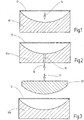
- Fig. 1 shows gravity lowering.
- a glass plate 12 is placed on a preheated mold 10 and further heated in a suitable manner.
- the glass plate 12 gradually lies against the surface of the mold 10 in the direction of arrow 14 under the influence of its gravity.
- Fig. 2 shows the same process with vacuum support, which is also known as vacuum sinking or deep drawing.
- a mold 10a is provided with one or more suction channels 16, which are acted upon by a vacuum in the direction of arrow 18.
- the glass plate 12 here, with additional support from the vacuum, lies against the inner surface of the mold 10a.
- ⁇ U> Tab. 1 ⁇ / u> Composition (% by weight) SiO 2 28.0 Al 2 O 3 1.0 K 2 O 1.0 BaO 4.0 ZrO 2 1.0 PbO 64.5 Sb 2 O 3 0.5 Density (kg / m 3 ) > 5050 refractive index 1.79 Transformationstemp.
- Fig. 3 the press molding of a glass plate 12 is shown schematically.
- the glass plate 12 is again placed on a preheated mold 10b and preferably further heated in an oven.
- a stamp 20 moves downward in the direction of arrow 22, thereby supporting the glass plate 12 of the stamp 20 is pressed into the mold 10b.
- the stamp 20 here has a significantly lower temperature than the glass plate 12 and than the mold 12b. In this way, sticking is counteracted.
- the surface of the stamp is covered with a suitable release agent, for example with a glass silk fabric. This further counteracts a tendency to stick.
- the method according to the invention for bending radiation protection glass was tested on the glass RD 50® using all three bending methods.
- the form 10 or 10a or 10b consisted of the martensitic steel 1.4122 in all cases. According to the manufacturer (ThyssenKrupp Materials Switzerland), this has a chemical composition of 0.33 to 0.45% by weight C, 15.5 to 17.5% by weight Cr, 0.8 to 1.3% by weight Mo and 0 to 1.0 wt% Ni.
- the molds were prepared by grinding or turning and the surface was finally finely turned or ground.
- the heat treatment by annealing, hardening and tempering was carried out according to the manufacturer's instructions.
- Samples of 500 x 800 mm and a thickness of 6 mm were made from the glass RD 50®.
- This glass is produced in a gas-operated melting furnace, in which all components required for glass production are placed in a clay port and melted under great heat. The glass melt is then rolled out between two steel rollers to form glass plates and annealed in a cooling furnace. This process damages the surfaces so that they cannot be viewed. This is followed by double-sided surface processing by grinding with diamond-tipped tools and polishing with the help of polishing felts and cerium oxide to produce a transparent pane.
- the mold 10 was first treated with a release agent, for example with graphite powder, and then preheated to 350 to 400 ° C. in an oven. A cold glass plate was then placed on top. Then the furnace was further heated to 400 ° C. over a period of 60 minutes and finally heated to approximately 480 ° C. over a period of 30 minutes. Here, gravity was lowered, as in Fig. 1 shown. This was followed by cooling in mold 10 with the following temperature program: cooling to 400 ° C. over 60 minutes, further cooling to 300 ° C. over 70 minutes, further cooling to 200 ° C. over 60 minutes, further cooling to 150 ° C. over 20 minutes , finally cooling to 70 ° C over 30 minutes.
- a release agent for example with graphite powder
- the shaped glass body was then removed.
- Example 2 The same data as in Example 1 were used. In addition, however, as in Fig. 2 shown schematically, worked with vacuum support. A vacuum of approximately 70 kPa was applied to the mold 10a.
- a glass plate 500 x 800 mm x 6 mm thick made of radiation protection glass RD 50® was used.
- the mold 10b was produced in the same manner as described above and pretreated by applying a release agent (graphite powder). There has now been a double pressing process in accordance with Fig. 3 applied.
- the mold was first preheated in the oven to about 350 to 400 ° C, the cold glass plate was placed on it and then briefly heated again in the oven to about 400 to 450 ° C. Then the mold 10b with the glass plate 12 lying thereon was made extended the furnace and a stamp 20 consisting of an aluminum alloy and covered with a glass fiber fabric by a pneumatic cylinder gradually approached to a maximum pressing pressure of about 6 bar from above in order to press the glass plate 12 against the inner surface of the mold 10b. The pressing process took about 4 to 5 seconds. Subsequently, the stamp was immediately moved upwards again and the mold 10b with the pressing body placed on it was returned to the oven and from 400 ° C. again cooled down to 70 ° C. using the same program as in Examples 1 and 2, that is to say hold first over 60 minutes at 400 ° C, then cooling to 300 ° C over 70 minutes etc.
- the glass plate was deformed downwards by an amount of approx. 200 mm. It was a 3-dimensional deformation.
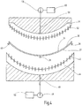
- Thermal tempering is carried out according to Fig. 4 the vitreous body 30 is placed in a suitable manner on a frame on which it is supported in its edge region and optionally additionally in its central region at support points 36, 38, 40.
- the glass body 30 is then moved into a preheated oven of approximately 550 ° C. and heated to approximately 450 ° C. over a longer period of time of approximately 15 minutes.
- the glass body 30 is then moved out of the oven and blown on both its underside 32 and on its top side via a plurality of nozzles 42 and 52.
- the air is fed into a distribution space 44 via a duct 46 via a blower 48, which draws in via a filter 50.
- the distribution space 44 has on it the top of the glass body 30 facing a plurality of nozzles 42, which are arranged at equal distances from each other and cover the entire surface.
- a distributor space 54 is provided above the glass body 30, the outer surface of which is modeled approximately on the shape of the glass body 30 and on which a plurality of nozzles 52 are located.
- air is drawn in from the outside via a blower 58 and a filter 60 and led into the distribution space 54 via a duct 56.
- the outflow pressure is around 15 millibars.
- a glass plate made of radiation protection glass RD 50® of size 500 x 800 mm with a thickness of 6 mm was first bent according to example 1 and then placed on a frame and in its edge area at a total of 12-16 support points and additionally in the middle area by 4- 8 support points supported. After preheating in the oven at 550 ° C. for about 15 minutes, the glass body 30 was moved out of the oven and flowed with blown air from both sides until the temperature on its surface had dropped to about 100 ° C. The cooling process was then ended and there was a natural cooling to room temperature.
- a quenching test (TWB test according to DIN IEC 60747) was carried out on glass bodies shaped according to Example 1 (not thermally tempered) and additionally thermally tempered glass bodies according to Example 4.
- the vitreous bodies are heated to 70 ° C to 160 ° C and then brewed with cold water at approx. 15 ° C.
- Tempered glass bodies on the other hand, were heated up to 160 ° C without breaking when they were rinsed with cold water. Then the test was stopped.
Landscapes
- Chemical & Material Sciences (AREA)
- Engineering & Computer Science (AREA)
- Materials Engineering (AREA)
- Organic Chemistry (AREA)
- Physics & Mathematics (AREA)
- Thermal Sciences (AREA)
- Mathematical Physics (AREA)
- Mechanical Engineering (AREA)
- Metallurgy (AREA)
- Life Sciences & Earth Sciences (AREA)
- Chemical Kinetics & Catalysis (AREA)
- General Chemical & Material Sciences (AREA)
- Geochemistry & Mineralogy (AREA)
- Re-Forming, After-Treatment, Cutting And Transporting Of Glass Products (AREA)
- Glass Compositions (AREA)
Description
- Die Erfindung betrifft ein Verfahren zum thermischen Vorspannen eines Strahlenschutzglases bzw. eines daraus bestehenden Glaskörpers.
- Im Rahmen dieser Anmeldung wird unter einem "Strahlenschutzglas" ein Glas mit einer Dichte von mindestens 4000 kg/m3 verstanden, das den Anforderungen an Bleiglasscheiben gemäß der deutschen und europäischen Normen DIN EN 61331-1 (Fassung August 2006) und DIN EN 61331-2 (Fassung April 2002) genügt, d.h. der Schwächungsgleichwert in mm Pb darf nicht kleiner sein als das 0,22-fache der minimal erlaubten Bleiglasscheibe in Millimeter sein. Die obigen Normen beruhen auf der internationalen Norm IEC 61331-1:1994 und der IEC 61331-2:1994 und sind damit harmonisiert.
- Solche Strahlenschutzgläser werden als Schutzgläser gegen Röntgen- und Gammastrahlen im medizinischem und technischem Bereich verwendet. Sie werden insbesondere in Strahlenschutztüren und -fenster eingebaut. Der Schwächungsgleichwert wird gemäß der Norm durch Vergleich zwischen der Strahlenschutzwirkung einer Bleiglasplatte und einer Platte aus Strahlenschutzglas ermittelt. Ein Schwächungsgleichwert von 0,22 bedeutet, dass das Strahlenschutzglas an seiner minimal zugelassenen Dicke noch 22 % der Schutzwirkung einer Bleiglasplatte gleicher Dicke hat.
- Im engeren Sinne wird unter einem Strahlenschutzglas ein Glas verstanden, das gemäß der obigen Normen einen Schwächungsgleichwert von mindestens 25 %, vorzugsweise von mindestens 28 % für eine Nenndicke zwischen 6,5 und 25 mm bei einer Röhrenspannung von bis zu 200 kV mit 1,2 mm Cu Gesamtfilterung aufweist.
- Es kann sich hierbei z.B. um ein Glas handeln, das einen Schwermetalioxidgehalt von mindestens 50 Gew.-% aufweist. Es kann sich hierbei etwa um ein Schwerflintglas handeln, das vorzugsweise einen Bleioxidgehalt von mindestens 60 Gew.-% aufweist.
- Durch diesen hohen Schwermetalloxidgehalt weisen derartige Gläser eine hohe Dichte (mehr als 4000 kg/m3 oder sogar mehr als 4900 kg/m3) und eine relativ niedrige Transformationstemperatur (<500 °C) auf.
- Solche Gläser weisen außerdem eine gegenüber herkömmlichen Kalknatrongläsern reduzierte mechanische und chemische Stabilität bzw. Festigkeit der Oberflächen auf. Ein solches Glas ist beispielsweise aus der
EP 2 036 714 A1 bekannt. - Ein thermisches Vorspannen derartiger Gläser ist mit bekannten Verfahren nicht möglich. Gleichermaßen ist ein Biegen mit bekannten Biegeverfahren nicht möglich (vgl. zum Beispiel
US 5 372 624 A ). - Aus der
US 5 372 624 A ist ein Verfahren zum Biegen einer Glasplatte bekannt, bei dem eine Glasplatte zunächst in einem Ofen vorgeheizt wird, dann in eine Biegezelle überführt wird, wobei die Temperatur auf der Glasbiegetemperatur gehalten wird und die Platte dann zwischen einer oberen Form und einer unteren Form gebogen wird, indem die untere Form gegen die Glasplatte angehoben wird. - Der Erfindung liegt somit die Aufgabe zugrunde, ein Verfahren zum thermischen Vorspannen von Strahlenschutzglas anzugeben, mit dem eine zuverlässige thermische Vorspannung mit hoher Qualität gewährleistet ist.
- Diese Aufgabe wird erfindungsgemäß durch ein Verfahren zum thermischen Vorspannen eines plattenförmigen Glaskörpers aus einem Strahlenschutzglas mit einer Dichte von mindestens 4000 kg/m3 gelöst, mit den folgenden Schritten:
- Abstützen des Glaskörpers zumindest an seinem Außenumfang an einer Reihe von Auflagepunkten;
- Einführen des Glaskörpers in einen Ofen, der auf eine Temperatur von 500 bis 600°C, vorzugsweise auf 530 bis 570°C vorgeheizt ist;
- Aufheizen des Glaskörpers auf 400°C bis 500°C, vorzugsweise auf 430 bis 470°C;
- Entnehmen des Glaskörpers aus dem Ofen und Anblasen des Glaskörpers auf beiden Seiten mit einem kalten Fluid aus einer Mehrzahl von Düsen, bis sich der Glaskörper auf eine Oberflächentemperatur von höchstens 150°C, vorzugsweise auf höchstens 120°C, besonders bevorzugt auf höchstens 100°C abgekühlt hat.
- Es hat sich gezeigt, dass mit einer derartigen Verfahrensführung ein thermisches Vorspannen eines aus einem Strahlenschutzglas bestehenden Glaskörpers in zuverlässiger Weise möglich ist und sich eine deutliche Festigkeitserhöhung gegenüber einem nicht thermisch vorgespannten Glaskörper ergibt.
- Gemäß einer weiteren Ausgestaltung der Erfindung wird der Glaskörper mit Blasluft angeblasen, die vorzugsweise annähernd Raumtemperatur aufweist oder die gekühlt ist.
- Hierbei tritt das Fluid bzw. die Blasluft vorzugsweise mit einem Druck von 10 bis 20 Millibar in Richtung auf den Glaskörper aus.
- Unter diesen Randbedingungen wird eine zuverlässige thermische Vorspannung des aus einem Strahlenschutzglas bestehenden Glaskörpers ermöglicht.
- In zusätzlicher Weiterbildung des erfindungsgemäßen Verfahrens erfolgt vor dem thermischen Vorspannen ein Biegen des Strahlenschutzglases mit den folgenden Schritten:
- (a) Bereitstellen einer Form;
- (b) Bereitstellen einer Glasplatte aus einem Strahlenschutzglas;
- (c) Vorheizen der Form auf eine Temperatur von 300 bis 400°C;
- (d) Auflegen der Glasplatte auf die Form;
- (e) gemeinsames Aufheizen der Glasplatte und der Form auf eine Temperatur von 370 bis 430°C;
- (f) Aufheizen auf eine Temperatur von 400°C bis 500°C, vorzugsweise auf eine Temperatur von 440 bis 500°C, wobei die Schritte (e) und (f) zusammen mindestens 30 Minuten, vorzugsweise mindestens 60 Minuten dauern;
- (g) Formen der Glasplatte und
- (h) Abkühlen des geformten Glases mittels eines Kühlprogrammes über einen Zeitraum von mindestens 60 Minuten, vorzugsweise über mindestens 120 Minuten.
- Es hat sich gezeigt, dass mit einem derartigen Temperaturprogramm eine Glasplatte aus einem Strahlenschutzglas mit hoher Präzision verformt werden kann.
- Hierbei kann im einfachsten Fall die Glasplatte unter Schwerkrafteinfluss geformt werden.
- Infolge des hohen Gewichtes der Glasplatte führt die Biegung unter Schwerkrafteinfluss zu deutlich besseren Ergebnissen als beim Formen von herkömmlichen Glasplatten.
- Vorzugsweise erfolgt das Aufheizen, Formen und Kühlen bei dieser Verfahrensvariante innerhalb eines Ofens.
- Gemäß einer weiteren Verfahrensvariante wird der Formvorgang durch Anlegen eines Vakuums unterstützt.
- Auf diese Weise kann der Formvorgang selbst beschleunigt werden und eine noch höhere Präzision bei der Einhaltung der geometrischen Toleranzen des gebogenen bzw. geformten Strahlenschutzglases erreicht werden.
- Gemäß einer weiteren Ausgestaltung der Erfindung wird die Glasplatte durch einen Stempel, der vorzugsweise aus einer Aluminiumlegierung oder einer Magnesiumlegierung besteht, in die Form gepresst.
- Hierdurch kann der Formvorgang beschleunigt werden und außerdem eine besonders hohe Präzision bei der Einhaltung der geometrischen Parameter gewährleistet werden.
- Vorzugsweise weist hierbei der Stempel an seiner Oberfläche eine Trennschicht auf, die vorzugsweise aus einem Glasseidegewebe besteht.
- Hierdurch wird ein Anhaften am Stempel vermieden.
- Vorzugsweise wird hierbei der Stempel auf eine Temperatur vorgeheizt, die mindestens 100 K unterhalb der Vorheiztemperatur der Form liegt, vorzugsweise 120 bis 180°C beträgt, weiter bevorzugt 140 bis 160°C beträgt.
- Gemäß einer weiteren Ausgestaltung der Erfindung beträgt der Anpressdruck maximal 15 bar, vorzugsweise maximal 10 bar, weiter bevorzugt maximal 8 bar und wird allmählich aufgebaut.
- Hierzu kann beispielsweise ein Pneumatikzylinder verwendet werden, der den Maximaldruck allmählich aufbaut.
- Die Presszeit beträgt vorzugsweise 2 bis 30 Sekunden, weiter bevorzugt 3 bis 10 Sekunden, besonders bevorzugt 4 bis 6 Sekunden.
- Bei Verwendung derartiger Pressbedingungen ergibt sich eine hohe Qualität und eine gute Einhaltung der geometrischen Toleranzen.
- Vorzugsweise wird die Form mit der aufgelegten Glasplatte zunächst im Ofen vorgewärmt auf eine Temperatur von etwa 400 bis 450°C, dann zum Pressen aus dem Ofen herausgefahren und anschließend zur Durchführung des Kühlprogrammes wieder in den Ofen eingefahren.
- Im Ofen erfolgt dann die gesteuerte Abkühlung mittels eines Kühlprogrammes über einen Zeitraum von mindestens 60 Minuten, vorzugsweise über mindestens 120 Minuten.
- Hierbei wird vorzugsweise von einer Temperatur von unterhalb der unteren Kühltemperatur aus abkühlt, vorzugsweise beginnend mit einer Temperatur, die 30 bis 100 K unterhalb der unteren Kühltemperatur liegt, vorzugsweise beginnend bei 380 bis 420°C.
- Unter Verwendung eines derartigen Kühlprogrammes lassen sich Spannungen im geformten Glaskörper sicher vermeiden.
- Gemäß einer weiteren Ausgestaltung der Erfindung wird eine Form verwendet, die aus einem vergüteten martensitischen Stahl besteht, vorzugsweise mit einem C-Gehalt von 0,2 bis 0,6 Gew.-%, weiter bevorzugt mit einem C-Gehalt von 0,3 bis 0,5 Gew.-%, weiter bevorzugt aus einem Stahl mit einem Chromgehalt von 14 bis 19 Gew.-%, einem Molybdängehalt von 0,5 bis 2 Gew.-% und einem Nickelgehalt von 0 bis 2 Gew.-% besteht, besonders bevorzugt aus dem Stahl Nr. 1.4122 besteht.
- Es hat sich gezeigt, dass die Verwendung eines derartigen vergüteten Stahls eine geringe Abnutzung und ein zunderfreies Arbeiten mit einer hohen Standfestigkeit ergibt.
- In weiter bevorzugter Ausführung der Erfindung wird die Oberfläche der Form mit einem Trennmittel beschichtet. Hierbei kann es sich beispielsweise um Graphitpulver oder Bornitridpulver handeln.
- Durch diese Maßnahme wird ein Kleben des Glaskörpers an der Form vermieden.
- Der vorstehend beschriebene Biegevorgang und die vorstehend beschriebene thermische Vorspannung des Strahlenschutzglases eignet sich insbesondere für ein Strahlenschutzglas mit einem sehr hohen Schwermetalloxidanteil, das eine Dichte von mindestens 4000 kg/m3, vorzugsweise von mindestens 4900 kg/m3 aufweist.
- Hierbei handelt es sich vorzugsweise um ein Schwerflintglas, das einen Bleioxidgehalt von mindestens 60 Gew.-% aufweist.
- Ferner kann das Strahlenschutzglas vorzugsweise als Hauptbestandteile neben Bleioxid 25 bis 30 Gew.-% Siliciumoxid und 2 bis 6 Gew.-% Bariumoxid enthalten.
- Ferner kann das Strahlenschutzglas zusätzlich 0,1 Gew.-% bis 3 Gew.-%, vorzugsweise 0,5 bis 2 Gew.-% mindestens eines weiteren Bestandteils enthalten, der aus der Gruppe ausgewählt ist, die aus Aluminiumoxid, Zirkonoxid und einem Alkalioxid besteht, und optional Läutermittel in üblichen Mengen von bis zu 2 Gew.- % enthalten.
- Ferner kann das Strahlenschutzglas eine Dicke von 3,0 bis 25,0 mm aufweisen.
- Weitere Merkmale und Vorteile der Erfindung ergeben sich aus der nachfolgenden Beschreibung bevorzugter Ausführungsbeispiele unter Bezugnahme auf die Zeichnung. Es zeigen:
- Fig. 1
- eine schematische Darstellung eines Glasbiegevorgangs unter Ausnutzung von Schwerkraftsenken;
- Fig. 2
- eine schematische Darstellung eines Glasbiegevorgangs unter Ausnutzung von Vakuumsenken;
- Fig. 3
- eine schematische Darstellung eines Glasbiegevorgangs unter Verwendung eines Presssenkens und
- Fig. 4
- eine schematische Darstellung eines erfindungsgemäßen thermischen Vorspannens von Strahlenschutzglas.
- In Tabelle 1 sind die wichtigsten Daten des Strahlenschutzglases RD 50® zusammengefasst, das von der Schott AG, Mainz, hergestellt und vertrieben wird.
- In den
Fig. 1 bis 3 sind schematisch verschiedene Möglichkeiten zum Formen bzw. 3-dimensionalen Biegen von Glas dargestellt. Diese werden optional einem erfindungsgemäßen thermischen Vorspannen gemäßFig. 4 vorgeschaltet. -
Fig. 1 zeigt das Schwerkraftsenken. Hierbei wird eine Glasplatte 12 auf eine vorgeheizte Form 10 aufgelegt und weiter in geeigneter Weise aufgeheizt. Die Glasplatte 12 legt sich allmählich unter dem Einfluss ihrer Schwerkraft in Richtung des Pfeiles 14 an die Oberfläche der Form 10 an. -
Fig. 2 zeigt den gleichen Vorgang mit Vakuumunterstützung, der auch als Vakuumsenken oder Tiefziehen bekannt ist. Eine Form 10a ist hierbei mit einem oder mehreren Saugkanälen 16 versehen, die in Richtung des Pfeiles 18 mit einem Vakuum beaufschlagt werden. Die Glasplatte 12 legt sich hierbei mit zusätzlicher Unterstützung durch das Vakuum an die Innenoberfläche der Form 10a an.Tab. 1 Zusammensetzung (Gew.-%) SiO2 28,0 Al2O3 1,0 K2O 1,0 BaO 4,0 ZrO2 1,0 PbO 64,5 Sb2O3 0,5 Dichte (kg/m3) > 5050 Brechungsindex 1,79 Transformationstemp. Tg(°C) 467 (α20-300 (ppm) 7,4 Viskosität Ig η (dPas) Temp. (°C) Untere Kühltemp. 14,5 444 Obere Kühltemp. 13,0 467 Erweichungstemp. 7,6 603 Formgebungstemp. 6,0 673 Formgebungstemp. 5,0 729 Formgebungstemp. 4,0 800 Schwächungsgleichwert (für Pb in % der Glasdicke): für Nenndicke 7,5 mm bei 100 kV/0,25 mm Cu 30,5 bei 200 kV/1,20 mm Cu 28,6 für Nenndicke ≥ 10 mm bei 100 kV/0,25 mm Cu 30,0 bei 200 kV/1,20 mm Cu 28,9 - In
Fig. 3 ist das Pressformen einer Glasplatte 12 schematisch dargestellt. Die Glasplatte 12 wird wiederum auf eine vorgeheizte Form 10b aufgelegt und vorzugsweise in einem Ofen weiter aufgeheizt. Zum eigentlichen Formvorgang fährt ein Stempel 20 in Richtung des Pfeiles 22 nach unten, wodurch die Glasplatte 12 mit Unterstützung des Stempels 20 in die Form 10b gedrückt wird. Der Stempel 20 weist hierbei eine deutlich geringere Temperatur als die Glasplatte 12 und als die Form 12b auf. Auf diese Weise wird einem Kleben entgegengewirkt. Zusätzlich ist die Oberfläche des Stempels mit einem geeigneten Trennmittel, zum Beispiel mit einem Glasseidegewebe bespannt. Hierdurch wird einer Klebeneigung weiter entgegengewirkt. - Das erfindungsgemäße Verfahren zum Biegen von Strahlenschutzglas wurde am Glas RD 50® nach allen drei Biegeverfahren erprobt.
- Die Form 10 bzw. 10a bzw. 10b bestand in allen Fällen aus dem martensitischen Stahl 1.4122. Dieser hat nach Herstellerangaben (ThyssenKrupp Materials Schweiz) eine chemische Zusammensetzung von 0,33 bis 0,45 Gew.-% C, 15,5 bis 17,5 Gew.-% Cr, 0,8 bis 1,3 Gew.-% Mo und 0 bis 1,0 Gew.-% Ni.
- Die Formen wurden durch Schleifen oder Drehen vorgearbeitet und die Oberfläche schließlich feinstgedreht bzw. geschliffen.
- Die Wärmebehandlung durch Glühen, Härten und Anlassen erfolgte nach Herstellerangabe.
- Es wurden Proben von 500 x 800 mm und einer Dicke von 6 mm aus dem Glas RD 50® hergestellt. Die Herstellung dieses Glases erfolgt in einem gasbetriebenen Schmelzofen, in dem alle zur Glasherstellung benötigten Komponenten in einem Tonhafen gegeben und unter großer Hitze verschmolzen werden. Die Glasschmelze wird dann zwischen zwei Stahlwalzen zu Glasplatten ausgewalzt und in einem Kühlofen getempert. Durch diesen Prozess werden die Oberflächen beschädigt, so dass eine Durchsicht nicht möglich ist. Anschließend erfolgt eine beidseitige Oberflächenbearbeitung durch Schleifen mit diamantbesetzten Werkzeugen und ein Polieren mit Hilfe von Polierfilzen und Ceroxid, um eine transparente Scheibe herzustellen.
- Aus derartigen Glasplatten wurden Proben der Größe von 500 x 800 mm mit einer Dicke von 6 mm zugeschnitten.
- Die Form 10 wurde zunächst mit einem Trennmittel behandelt, beispielsweise mit Graphitpulver, und anschließend in einem Ofen zunächst auf 350 bis 400°C vorgeheizt. Anschließend wurde eine kalte Glasplatte aufgelegt. Dann erfolgte eine weitere Aufheizung im Ofen auf 400°C über einen Zeitraum von 60 Minuten und schließlich eine Aufheizung auf etwa 480°C über einen Zeitraum von 30 Minuten. Dabei erfolgte ein Schwerkraftsenken, wie in
Fig. 1 dargestellt. Anschließend erfolgte die Abkühlung in der Form 10 mit folgendem Temperaturprogramm: Abkühlung auf 400°C über 60 Minuten, weitere Abkühlung auf 300°C über 70 Minuten, weitere Abkühlung auf 200°C über 60 Minuten, weitere Abkühlung auf 150°C über 20 Minuten, schließlich Abkühlung auf 70°C über 30 Minuten. - Anschließend wurde der geformte Glaskörper entnommen.
- Es wurden die gleichen Daten wie beim Beispiel 1 verwendet. Zusätzlich wurde jedoch, wie in
Fig. 2 schematisch dargestellt, mit Vakuumunterstützung gearbeitet. Die Form 10a wurde mit einem Unterdruck von etwa 70 kPa beaufschlagt. - Wie bei den Beispielen 1 und 2 wurde eine Glasplatte von 500 x 800 mm x Dicke von 6 mm aus dem Strahlenschutzglas RD 50® verwendet. Die Form 10b wurde in der gleichen Weise wie vorstehend beschrieben hergestellt und vorbehandelt durch Aufbringen eines Trennmittels (Graphitpulver). Es wurde nunmehr ein Doppelpressverfahren gemäß
Fig. 3 angewendet. - Hierzu wurde zunächst die Form im Ofen auf etwa 350 bis 400°C vorgeheizt, die kalte Glasplatte aufgelegt und dann nochmals im Ofen auf etwa 400 bis 450°C kurz erwärmt. Anschließend wurde die Form 10b mit der aufliegenden Glasplatte 12 aus dem Ofen ausgefahren und ein Stempel 20 bestehend aus einer Aluminiumlegierung und bespannt mit einem Glasseidegewebe durch einen Pneumatikzylinder allmählich bis auf einen maximalen Pressdruck von etwa 6 bar von oben angefahren, um die Glasplatte 12 gegen die Innenoberfläche der Form 10b zu pressen. Der Pressvorgang dauerte etwa 4 bis 5 Sekunden. Anschließend wurde der Stempel sofort wieder nach oben weg gefahren und die Form 10b mit dem aufliegenden Presskörper wieder in den Ofen gefahren und ab 400°C wieder mit dem gleichen Programm wie bei den Beispielen 1 und 2 bis auf 70°C abgekühlt, also zunächst Halten über 60 Minuten bei 400°C, dann Abkühlen auf 300°C über 70 Minuten usw.
- In allen drei Fällen wurde die Glasplatte um einen Betrag von ca. 200 mm in der Mitte nach unten verformt. Es handelte sich hierbei um eine 3-dimensionale Verformung.
- In allen drei Fällen ergaben sich gute Toleranzen und Oberflächenqualitäten der hergestellten Formkörper.
- Eine Verformung bis auf eine Halbkugelform oder eine entsprechend geformte Rinne ist möglich.
- Durch Schwerkraftsenken hergestellte Glasgeometrien gemäß Beispiel 1 wurden anschließend durch thermisches Vorspannen weiter bearbeitet.
- Beim thermischen Vorspannen wird gemäß
Fig. 4 der Glaskörper 30 in geeigneter Weise auf ein Gestell gelegt, auf dem er in seinem Randbereich und gegebenenfalls zusätzlich in seinem mittleren Bereich an Auflagepunkten 36, 38, 40 unterstützt wird. Der Glaskörper 30 wird dann in einen vorgeheizten Ofen von ca. 550°C eingefahren und über einen längeren Zeitraum von ca. 15 Minuten auf ca. 450°C aufgeheizt. Anschließend wird der Glaskörper 30 aus dem Ofen ausgefahren und sowohl an seiner Unterseite 32 als auch an seiner Oberseite über eine Mehrzahl von Düsen 42 bzw. 52 angeblasen. Die Luft wird über ein Gebläse 48, das über einen Filter 50 ansaugt, über einen Kanal 46 in einen Verteilerraum 44 zugeführt. Der Verteilerraum 44 weist an seiner dem Glaskörper 30 zugewandten Oberseite eine Vielzahl von Düsen 42 auf, die in gleichmäßigen Abständen zueinander angeordnet sind und die gesamte Oberfläche bedecken. - In entsprechender Weise ist oberhalb des Glaskörpers 30 ein Verteilerraum 54 vorgesehen, dessen Außenoberfläche annähernd der Form des Glaskörpers 30 nachgebildet ist und an dem sich eine Vielzahl von Düsen 52 befinden. Wiederum wird über ein Gebläse 58 und einen Filter 60 Luft von außen angesaugt und über einen Kanal 56 in den Verteilerraum 54 geführt. Der Ausströmdruck liegt bei etwa 15 Millibar.
- Eine Glasplatte aus dem Strahlenschutzglas RD 50® der Größe 500 x 800 mm mit einer Dicke von 6 mm wurde zunächst gemäß Beispiel 1 gebogen und dann auf ein Gestell aufgelegt und in ihrem Randbereich an insgesamt 12-16 Auflagepunkten sowie zusätzlich im mittleren Bereich durch 4-8 Auflagepunkte abgestützt. Nach einem Vorheizen im Ofen von 550°C über etwa 15 Minuten wurde der Glaskörper 30 aus dem Ofen ausgefahren und von beiden Seiten mit Blasluft angeströmt, bis sich die Temperatur an seiner Oberfläche auf etwa 100°C abgesenkt hatte. Anschließend wurde der Kühlprozess beendet und es erfolgte eine natürliche Abkühlung auf Raumtemperatur.
- Ein Abschrecktest (TWB-Test nach DIN IEC 60747) wurde an gemäß Beispiel 1 geformten Glaskörpern (nicht thermisch vorgespannt) und gemäß Beispiel 4 zusätzlich thermisch vorgespannten Glaskörpern durchgeführt. Die Glaskörper werden auf 70 °C bis 160 °C aufgeheizt und anschließend mit kaltem Wasser von ca. 15 °C abgebraust.
- Bei nicht vorgespannten Glaskörpern trat schon bei Aufheizung auf 70°C und Abbrausen mit kaltem Wasser Bruch ein.
- Vorgespannte Glaskörper wurden dagegen auf bis zu 160°C aufgeheizt, ohne dass bei Abbrausen mit kaltem Wasser ein Bruch eintrat. Dann wurde der Test abgebrochen.
- Die Ergebnisse eines Kugelfalltestes (IEC 60601, alt DIN 4646) für vorgespannte und nicht vorgespannte Glaskörper sind in Tabelle 2 zusammengefasst.
Tabelle 2 Kugelfall-Test Fallhöhe (72 Gramm) 1,5 m 1,6 m 1,7 m 1,8 m Energie in Joule 1,059 1,130 1,201 1,271 Ohne Vorspannung OK OK OK Bruch Mit Vorspannung OK OK OK OK Fallhöhe (226 Gramm) 1,5 m 1,6 m 1,7 m 1,8 m Energie in Joule 3,326 3,547 3,769 3,991 Ohne Vorspannung Bruch --- --- --- Mit Vorspannung OK OK OK OK
Claims (15)
- Verfahren zum thermischen Vorspannen eines plattenförmigen Glaskörpers (30) aus einem Strahlenschutzglas mit einer Dichte von mindestens 4000 kg/m3 gemäß DIN EN 61331-1 (Fassung August 2006) und DIN EN 61331-2 (Fassung April 2002), mit den folgenden Schritten:- Abstützen des Glaskörpers (30) zumindest an seinem Außenumfang an einer Reihe von Auflagepunkten (36, 38, 40);- Einführen des Glaskörpers in einen Ofen, der auf eine Temperatur von 500 bis 600°C , vorzugsweise auf 530°C bis 570°C vorgeheizt ist;- Aufheizen des Glaskörpers auf 400°C bis 500°C, vorzugsweise auf 430°C bis 470°C;- Entnehmen des Glaskörpers (30) aus dem Ofen und Anblasen des Glaskörpers auf beiden Seiten mit einem kalten Fluid aus einer Mehrzahl von Düsen (42, 52), bis sich der Glaskörper (30) auf eine Oberflächentemperatur von höchstens 150°C, vorzugsweise auf höchstens 120°C, besonders bevorzugt auf höchstens 100°C abgekühlt hat.
- Verfahren nach Anspruch 1, bei dem das Strahlenschutzglas eine Dichte von mindestens 4900 kg/m3 aufweist, weiter bevorzugt ein Schwerflintglas ist, das vorzugsweise einen Schwermetalloxidgehait von mindestens 50 Gew.-% aufweist, besonders bevorzugt einen Bleioxidgehalt von mindestens 60 Gew.-% aufweist.
- Verfahren nach Anspruch 1 oder 2, bei dem vor dem thermischen Vorspannen zunächst ein Biegen des Strahlenschutzglases mit den folgenden Schritten durchgeführt wird:(a) Bereitstellen einer Form (10, 10a, 10b);(b) Bereitstellen einer Glasplatte (12) aus einem Strahlenschutzglas;(c) Vorheizen der Form auf eine Temperatur von 300 bis 400°C;(d) Auflegen der Glasplatte (12) auf die Form (10, 10a, 10b);(e) gemeinsames Aufheizen der Glasplatte (12) und der Form (10, 10a, 10b) auf eine Temperatur von 370 bis 430°C;(f) Aufheizen auf eine Temperatur von 400°C bis 500°C, vorzugsweise auf eine Temperatur von 440°C bis 500°C, wobei die Schritte (e) und (f) zusammen mindestens 30 Minuten, vorzugsweise mindestens 60 Minuten dauern;(g) Formen der Glasplatte (12) und(h) Abkühlen des geformten Glases mittels eines Kühlprogrammes über einen Zeitraum von mindestens 60 Minuten, vorzugsweise über mindestens 120 Minuten.
- Verfahren nach Anspruch 3, bei dem der Formvorgang durch Anlegen eines Vakuums unterstützt wird.
- Verfahren nach Anspruch 3 oder 4, bei dem die Glasplatte (12) durch einen Stempel (20), der vorzugsweise aus einer Aluminiumlegierung oder einer Magnesiumlegierung besteht, in die Form (10b) gepresst wird.
- Verfahren nach Anspruch 5, bei dem der Stempel (20) an seiner Oberfläche eine Trennschicht aufweist, die vorzugsweise aus einem Glasseidegewebe besteht.
- Verfahren nach Anspruch 5 oder 6, bei dem der Stempel (20) auf eine Temperatur vorgeheizt wird, die mindestens 100 K unterhalb der Vorheiztemperatur der Form liegt, vorzugsweise 120 bis 180°C beträgt, weiter bevorzugt, 140 bis 160°C beträgt.
- Verfahren nach einem der Ansprüche 5 bis 7, bei dem der Anpressdruck allmählich aufgebaut wird, bis ein Maximaldruck von 15 bar, vorzugsweise von 10 bar, weiter bevorzugt von 8 bar erreicht ist.
- Verfahren nach einem der Ansprüche 5 bis 8, bei dem die Presszeit 2 bis 30 Sekunden, vorzugsweise 3 bis 10 Sekunden, besonders bevorzugt 4 bis 6 Sekunden beträgt.
- Verfahren nach einem der Ansprüche 5 bis 9, bei dem die Form (10b) mit der aufgelegten Glasplatte (12) zum Pressen aus dem Ofen herausgefahren wird und anschließend zur Durchführung des Kühlprogrammes wieder in den Ofen gefahren wird.
- Verfahren nach einem der Ansprüche der Ansprüche 5 bis 10, bei dem das geformte Glas nach dem Pressvorgang mittels eines Kühlprogrammes über einen Zeitraum von mindestens 60 Minuten, vorzugsweise über mindestens 120 Minuten abgekühlt wird.
- Verfahren nach Anspruch 11, bei dem das geformte Glass von einer Temperatur von unterhalb der unteren Kühltemperatur aus abgekühlt wird, vorzugsweise beginnend mit einer Temperatur, die 30 bis 100 K unterhalb der unteren Kühltemperatur liegt, vorzugsweise beginnend bei 380 bis 420°C.
- Verfahren nach einem der Ansprüche 3 bis 12, bei dem eine Form (10, 10a, 10b) verwendet wird, die aus einem vergüteten martensitischen Stahl besteht, vorzugsweise mit einem C-Gehalt von 0,2 bis 0,6 Gew.-%, weiter bevorzugt mit einem C-Gehalt von 0,3 bis 0,5 Gew.-%, weiter bevorzugt aus einem Stahl mit einem Chromgehalt von 14 bis 19 Gew.-%, einem Molybdängehalt von 0,5 bis 2 Gew.-% und einem Nickelgehalt von 0 bis 2 Gew.-% besteht, besonders bevorzugt aus dem Stahl Nr. 1.4122 besteht.
- Verfahren nach einem der Ansprüche 3 bis 13, bei dem die Oberfläche der Form (10, 10a, 10b) mit einem Trennmittel beschichtet wird, vorzugsweise mit Graphitpulver oder mit Bornitridpulver.
- Thermisch vorgespannter Körper, bestehend aus einem Strahlenschutzglas mit einer Dichte von mindestens 4000kg/m3 gemäß DIN EN 61331-1 (Fassung August 2006) und DIN EN 61331-2 (Fassung April 2002), hergestellt nach einem Verfahren gemäß einem der vorhergehenden Ansprüche.
Applications Claiming Priority (3)
| Application Number | Priority Date | Filing Date | Title |
|---|---|---|---|
| DE102009024234 | 2009-05-28 | ||
| DE102009036164A DE102009036164B4 (de) | 2009-05-28 | 2009-07-28 | Verfahren zum Biegen und thermischen Vorspannen von Strahlenschutzglas |
| EP10164001A EP2256094A1 (de) | 2009-05-28 | 2010-05-27 | Verfahren zum Biegen und thermischen Vorspannen von Strahlenschutzglas |
Related Parent Applications (1)
| Application Number | Title | Priority Date | Filing Date |
|---|---|---|---|
| EP10164001A Division EP2256094A1 (de) | 2009-05-28 | 2010-05-27 | Verfahren zum Biegen und thermischen Vorspannen von Strahlenschutzglas |
Publications (2)
| Publication Number | Publication Date |
|---|---|
| EP3056474A1 EP3056474A1 (de) | 2016-08-17 |
| EP3056474B1 true EP3056474B1 (de) | 2020-01-08 |
Family
ID=42651388
Family Applications (2)
| Application Number | Title | Priority Date | Filing Date |
|---|---|---|---|
| EP16163284.9A Active EP3056474B1 (de) | 2009-05-28 | 2010-05-27 | Verfahren zum thermischen vorspannen von strahlenschutzglas |
| EP10164001A Withdrawn EP2256094A1 (de) | 2009-05-28 | 2010-05-27 | Verfahren zum Biegen und thermischen Vorspannen von Strahlenschutzglas |
Family Applications After (1)
| Application Number | Title | Priority Date | Filing Date |
|---|---|---|---|
| EP10164001A Withdrawn EP2256094A1 (de) | 2009-05-28 | 2010-05-27 | Verfahren zum Biegen und thermischen Vorspannen von Strahlenschutzglas |
Country Status (4)
| Country | Link |
|---|---|
| US (1) | US8783065B2 (de) |
| EP (2) | EP3056474B1 (de) |
| JP (1) | JP5417256B2 (de) |
| DE (1) | DE102009036164B4 (de) |
Families Citing this family (29)
| Publication number | Priority date | Publication date | Assignee | Title |
|---|---|---|---|---|
| DE102011015593B4 (de) * | 2011-03-30 | 2012-11-15 | Docter Optics Gmbh | Verfahren zum Herstellen eines Solarkonzentrators |
| US8783066B2 (en) * | 2011-05-27 | 2014-07-22 | Corning Incorporated | Glass molding system and related apparatus and method |
| US9038421B2 (en) * | 2011-07-01 | 2015-05-26 | Sunpower Corporation | Glass-bending apparatus and method |
| CN103030262A (zh) * | 2011-09-30 | 2013-04-10 | 富泰华工业(深圳)有限公司 | 曲面玻璃板的成型方法与其采用的成型设备 |
| JP2014141356A (ja) * | 2013-01-22 | 2014-08-07 | Nippon Electric Glass Co Ltd | 結晶化ガラス屈曲板の製造方法 |
| KR101446108B1 (ko) | 2013-03-27 | 2014-10-06 | 주식회사 원익큐엔씨 | 진공로를 이용한 석영판 성형방법 및 성형몰드 |
| WO2014167894A1 (ja) * | 2013-04-10 | 2014-10-16 | 日本電気硝子株式会社 | 曲面形状を有するガラス板の製造方法及び曲面形状を有するガラス板 |
| KR20150000611A (ko) * | 2013-06-25 | 2015-01-05 | 삼성디스플레이 주식회사 | 입체 유리의 제조 장치 및 제조 방법 |
| KR102412648B1 (ko) * | 2015-09-22 | 2022-06-24 | 삼성디스플레이 주식회사 | 글래스 성형 방법 |
| DE102017200413A1 (de) * | 2016-02-02 | 2017-08-03 | Schott Ag | Röntgen- und Gamma-Strahlen abschirmendes Glas |
| WO2017161104A1 (en) * | 2016-03-17 | 2017-09-21 | Corning Incorporated | Methods and apparatus for supporting glass |
| US11419231B1 (en) | 2016-09-22 | 2022-08-16 | Apple Inc. | Forming glass covers for electronic devices |
| US10800141B2 (en) | 2016-09-23 | 2020-10-13 | Apple Inc. | Electronic device having a glass component with crack hindering internal stress regions |
| US11565506B2 (en) | 2016-09-23 | 2023-01-31 | Apple Inc. | Thermoformed cover glass for an electronic device |
| US11535551B2 (en) * | 2016-09-23 | 2022-12-27 | Apple Inc. | Thermoformed cover glass for an electronic device |
| US11066322B2 (en) | 2017-12-01 | 2021-07-20 | Apple Inc. | Selectively heat-treated glass-ceramic for an electronic device |
| US10611666B2 (en) | 2017-12-01 | 2020-04-07 | Apple Inc. | Controlled crystallization of glass ceramics for electronic devices |
| US11420900B2 (en) | 2018-09-26 | 2022-08-23 | Apple Inc. | Localized control of bulk material properties |
| US11680010B2 (en) | 2019-07-09 | 2023-06-20 | Apple Inc. | Evaluation of transparent components for electronic devices |
| CN112448072A (zh) * | 2019-09-03 | 2021-03-05 | Oppo广东移动通信有限公司 | 电子设备、电池盖、及其制造方法 |
| CN115955798A (zh) | 2020-03-28 | 2023-04-11 | 苹果公司 | 用于电子设备壳体的玻璃覆盖构件 |
| US11460892B2 (en) | 2020-03-28 | 2022-10-04 | Apple Inc. | Glass cover member for an electronic device enclosure |
| US11666273B2 (en) | 2020-05-20 | 2023-06-06 | Apple Inc. | Electronic device enclosure including a glass ceramic region |
| CN111716688B (zh) * | 2020-06-29 | 2021-04-06 | 东莞市铂华光电材料有限公司 | 一种盖板热弯防护成型工艺 |
| US12195379B2 (en) | 2020-12-17 | 2025-01-14 | Apple Inc. | Forming and bonding of glass components for portable electronic devices |
| WO2022133136A1 (en) | 2020-12-17 | 2022-06-23 | Apple Inc. | Fluid forming a glass component for a portable electronic device |
| US11945048B2 (en) | 2020-12-23 | 2024-04-02 | Apple Inc. | Laser-based cutting of transparent components for an electronic device |
| CN114538759B (zh) * | 2022-03-22 | 2022-09-20 | 阜阳市远大浮法玻璃制品有限公司 | 一种钢化玻璃弯曲成型装置 |
| CN114646218B (zh) * | 2022-05-19 | 2022-10-25 | 蒙娜丽莎集团股份有限公司 | 岩板热弯炉及对岩板进行热弯处理的方法 |
Family Cites Families (29)
| Publication number | Priority date | Publication date | Assignee | Title |
|---|---|---|---|---|
| US1449789A (en) * | 1921-11-17 | 1923-03-27 | Corning Glass Works | Mold |
| FR829348A (fr) * | 1937-02-18 | 1938-06-20 | Procédé et dispositif pour la trempe du verre | |
| US2736714A (en) * | 1952-01-04 | 1956-02-28 | Owens Corning Fiberglass Corp | Lead glass composition |
| US3155748A (en) * | 1960-08-03 | 1964-11-03 | American Optical Corp | Method of making optical components |
| US3414395A (en) * | 1964-03-03 | 1968-12-03 | Ppg Industries Inc | Method and apparatus for shaping glass sheets |
| GB1157090A (en) * | 1965-12-02 | 1969-07-02 | Triplex Safety Glass Co | Improvements in or relating to a method and apparatus for Bending Glass in Sheet Form |
| US4043782A (en) * | 1975-06-23 | 1977-08-23 | Libbey-Owens-Ford Company | Method of and apparatus for bending relatively thin glass sheets |
| US4072492A (en) * | 1976-11-26 | 1978-02-07 | Ppg Industries, Inc. | Glass bending lehr with pre-heat hood |
| US4115090A (en) * | 1977-07-28 | 1978-09-19 | Ppg Industries, Inc. | Shaping glass sheets by gravity sagging on solid molds |
| DE3114881C2 (de) | 1981-04-13 | 1983-02-10 | Schott Glaswerke, 6500 Mainz | Nachverformungsverfahren zur Herstellung von Präzisionsglaskörpern mit hoher Oberflächenqualität |
| US4375978A (en) * | 1981-07-01 | 1983-03-08 | Ppg Industries, Inc. | Lightweight outline mold with low thermal inertia for shaping glass sheets |
| DE3635834A1 (de) * | 1986-10-22 | 1988-05-05 | Schott Glaswerke | Entladungssichere und verfaerbungsresistente strahlenschutzglaeser |
| JP2668049B2 (ja) * | 1988-02-26 | 1997-10-27 | 株式会社オハラ | 光学ガラス |
| US4880453A (en) * | 1988-12-19 | 1989-11-14 | Corning Incorporated | Method for making glass articles with defect-free surfaces and soluble glasses therefor |
| DK258389D0 (da) | 1989-05-26 | 1989-05-26 | Ferrosan As | Aryloxyphenylpropylaminer, deres fremstilling og anvendelse |
| JPH0350138A (ja) * | 1989-07-18 | 1991-03-04 | Canon Inc | 光学ガラス |
| JPH0725568B2 (ja) * | 1989-11-28 | 1995-03-22 | 旭硝子株式会社 | ガラス組成物およびそれを用いた絶縁体 |
| FR2678261B1 (fr) * | 1991-06-27 | 1994-10-21 | Saint Gobain Vitrage Int | Procede et dispositif de bombage d'une feuille de verre. |
| US5221646A (en) * | 1991-07-15 | 1993-06-22 | The United States Of America As Represented By The Secretary Of Commerce | Neutron absorbing glass compositions |
| FI90044C (fi) * | 1992-02-12 | 1993-12-27 | Tamglass Eng Oy | Foerfarande foer boejning och haerdning av glasskiva |
| DE4412747A1 (de) * | 1994-04-15 | 1995-10-19 | Flachglas Ag | Preßbiegestation für das Biegen von Glasscheiben |
| US5994249A (en) * | 1997-07-25 | 1999-11-30 | Libbey-Owens-Ford Co. | Blue colored glass composition |
| JP4114121B2 (ja) * | 1999-05-25 | 2008-07-09 | 日本電気硝子株式会社 | プラズマディスプレーパネル用材料及びガラス組成物 |
| DE10055830A1 (de) * | 2000-11-11 | 2002-05-29 | Volker Bastian | Temperaturunabhängige Verbundsicherheitsplatte |
| FR2866328B1 (fr) * | 2004-02-16 | 2006-05-26 | Saint Gobain | Verre plat au plomb par flottage sur un bain de metal |
| JP2008286787A (ja) * | 2007-04-18 | 2008-11-27 | Nippon Electric Glass Co Ltd | 放射線遮蔽安全ガラス |
| EP2036714A1 (de) * | 2007-09-06 | 2009-03-18 | Schott AG | Element mit einem Schutzglas gegen ionisierende Strahlung |
| DE202008003804U1 (de) * | 2008-02-19 | 2009-06-25 | Schott Ag | Verbundsubstratelement |
| US9010153B2 (en) * | 2008-07-02 | 2015-04-21 | Corning Incorporated | Method of making shaped glass articles |
-
2009
- 2009-07-28 DE DE102009036164A patent/DE102009036164B4/de not_active Expired - Fee Related
-
2010
- 2010-05-27 EP EP16163284.9A patent/EP3056474B1/de active Active
- 2010-05-27 EP EP10164001A patent/EP2256094A1/de not_active Withdrawn
- 2010-05-27 JP JP2010121634A patent/JP5417256B2/ja not_active Expired - Fee Related
- 2010-05-28 US US12/790,059 patent/US8783065B2/en active Active
Non-Patent Citations (1)
| Title |
|---|
| None * |
Also Published As
| Publication number | Publication date |
|---|---|
| US20100316847A1 (en) | 2010-12-16 |
| JP2010275187A (ja) | 2010-12-09 |
| US8783065B2 (en) | 2014-07-22 |
| DE102009036164B4 (de) | 2011-06-09 |
| EP2256094A1 (de) | 2010-12-01 |
| EP3056474A1 (de) | 2016-08-17 |
| DE102009036164A1 (de) | 2010-12-02 |
| JP5417256B2 (ja) | 2014-02-12 |
Similar Documents
| Publication | Publication Date | Title |
|---|---|---|
| DE102009036164B4 (de) | Verfahren zum Biegen und thermischen Vorspannen von Strahlenschutzglas | |
| DE2640206C2 (de) | Verfahren zur Herstellung einer gekrümmten Verbundglaswindschutzscheibe | |
| EP1414762B1 (de) | Verfahren zum thermischen vorspannen von glasplatten | |
| EP1593658B1 (de) | Gefloatetes Lithium-Aluminosilikat-Flachglas mit hoher Temperaturbeständigkeit, das chemisch und thermisch vorspannbar ist | |
| DE69402661T2 (de) | Verfahren zur verstärkung eines glasgegenstandes | |
| DE102010043326B4 (de) | Verfahren zur festigkeitssteigernden Keramisierung eines gefloateten kristallisierbaren Glases, keramisiertes Floatglas und Verwendung des keramisierten Floatglases | |
| EP0638526A1 (de) | Brandschutzsicherheitsglas | |
| EP3187471B1 (de) | Thermisch vorgespanntes glaselement und seine verwendungen | |
| EP3356139B1 (de) | Verbundglas mit dünner innenscheibe und schalldämpfender thermoplastischer zwischenschicht | |
| CH686304A5 (de) | Verfahren zum Herstellen von ebenen oder gewoelbten Glasplatten. | |
| DE102011009769A1 (de) | Hochfestes Alkali-Alumo-Silikatglas | |
| DE102014119064A1 (de) | Glasfilm mit speziell ausgebildeter Kante, Verfahren zu dessen Herstellung sowie dessen Verwendung | |
| EP1314704A1 (de) | Thermisch vorspannbares Alkaliborosilikatglas, seine Herstellung und seine Verwendung | |
| DE112018003694T5 (de) | Gehärtetes Glas | |
| DE102004059728A1 (de) | Verfahren zur Herstellung von Glas- oder Glaskeramik und insbesondere Glas- oder Glaskeramik-Artikel | |
| EP2409834A1 (de) | Laminiertes, transparentes Scheibenset, Verfahren zu dessen Herstellung und Biegung und dessen Verwendung | |
| EP0839772A1 (de) | Verwendung eines Glaskörpers zur Erzeugung eines chemisch vorgespannten Glaskörpers | |
| EP1112974A2 (de) | Verfahren zum Herstellen vorgespannter oder gebogener Gläser | |
| DE202021004140U1 (de) | Vorrichtung zum Biegen von flachen Glasscheiben | |
| WO2015000090A2 (de) | Brandschutzglasscheibe und brandschutzverglasung | |
| LU102043B1 (de) | Verfahren zum Erhöhen der Festigkeit und/oder der Härte eines Glasgegenstandes | |
| DE102014113150A1 (de) | Glaselement mit niedriger Bruchwahrscheinlichkeit | |
| DE10102824B9 (de) | Thermisch vorgespannter Bildschirm für Kathodenstrahlröhren und Verfahren zu seiner Herstellung | |
| DE202020005522U1 (de) | Glasbiegevorrichtung mit Laserunterstützung | |
| DE19948655C1 (de) | Verfahren zur schnellen Herstellung von Glas- und Glaskeramikplatten mit erhöhter thermischer Beständigkeit |
Legal Events
| Date | Code | Title | Description |
|---|---|---|---|
| PUAI | Public reference made under article 153(3) epc to a published international application that has entered the european phase |
Free format text: ORIGINAL CODE: 0009012 |
|
| 17P | Request for examination filed |
Effective date: 20160331 |
|
| AC | Divisional application: reference to earlier application |
Ref document number: 2256094 Country of ref document: EP Kind code of ref document: P |
|
| AK | Designated contracting states |
Kind code of ref document: A1 Designated state(s): AL AT BE BG CH CY CZ DE DK EE ES FI FR GB GR HR HU IE IS IT LI LT LU LV MC MK MT NL NO PL PT RO SE SI SK SM TR |
|
| GRAP | Despatch of communication of intention to grant a patent |
Free format text: ORIGINAL CODE: EPIDOSNIGR1 |
|
| STAA | Information on the status of an ep patent application or granted ep patent |
Free format text: STATUS: GRANT OF PATENT IS INTENDED |
|
| INTG | Intention to grant announced |
Effective date: 20190904 |
|
| GRAS | Grant fee paid |
Free format text: ORIGINAL CODE: EPIDOSNIGR3 |
|
| GRAA | (expected) grant |
Free format text: ORIGINAL CODE: 0009210 |
|
| STAA | Information on the status of an ep patent application or granted ep patent |
Free format text: STATUS: THE PATENT HAS BEEN GRANTED |
|
| AC | Divisional application: reference to earlier application |
Ref document number: 2256094 Country of ref document: EP Kind code of ref document: P |
|
| AK | Designated contracting states |
Kind code of ref document: B1 Designated state(s): AL AT BE BG CH CY CZ DE DK EE ES FI FR GB GR HR HU IE IS IT LI LT LU LV MC MK MT NL NO PL PT RO SE SI SK SM TR |
|
| REG | Reference to a national code |
Ref country code: GB Ref legal event code: FG4D Free format text: NOT ENGLISH |
|
| REG | Reference to a national code |
Ref country code: CH Ref legal event code: EP |
|
| REG | Reference to a national code |
Ref country code: DE Ref legal event code: R096 Ref document number: 502010016452 Country of ref document: DE |
|
| REG | Reference to a national code |
Ref country code: IE Ref legal event code: FG4D Free format text: LANGUAGE OF EP DOCUMENT: GERMAN |
|
| REG | Reference to a national code |
Ref country code: AT Ref legal event code: REF Ref document number: 1222495 Country of ref document: AT Kind code of ref document: T Effective date: 20200215 |
|
| REG | Reference to a national code |
Ref country code: NL Ref legal event code: MP Effective date: 20200108 |
|
| REG | Reference to a national code |
Ref country code: LT Ref legal event code: MG4D |
|
| PG25 | Lapsed in a contracting state [announced via postgrant information from national office to epo] |
Ref country code: NL Free format text: LAPSE BECAUSE OF FAILURE TO SUBMIT A TRANSLATION OF THE DESCRIPTION OR TO PAY THE FEE WITHIN THE PRESCRIBED TIME-LIMIT Effective date: 20200108 Ref country code: LT Free format text: LAPSE BECAUSE OF FAILURE TO SUBMIT A TRANSLATION OF THE DESCRIPTION OR TO PAY THE FEE WITHIN THE PRESCRIBED TIME-LIMIT Effective date: 20200108 Ref country code: NO Free format text: LAPSE BECAUSE OF FAILURE TO SUBMIT A TRANSLATION OF THE DESCRIPTION OR TO PAY THE FEE WITHIN THE PRESCRIBED TIME-LIMIT Effective date: 20200408 Ref country code: FI Free format text: LAPSE BECAUSE OF FAILURE TO SUBMIT A TRANSLATION OF THE DESCRIPTION OR TO PAY THE FEE WITHIN THE PRESCRIBED TIME-LIMIT Effective date: 20200108 Ref country code: PT Free format text: LAPSE BECAUSE OF FAILURE TO SUBMIT A TRANSLATION OF THE DESCRIPTION OR TO PAY THE FEE WITHIN THE PRESCRIBED TIME-LIMIT Effective date: 20200531 |
|
| PG25 | Lapsed in a contracting state [announced via postgrant information from national office to epo] |
Ref country code: LV Free format text: LAPSE BECAUSE OF FAILURE TO SUBMIT A TRANSLATION OF THE DESCRIPTION OR TO PAY THE FEE WITHIN THE PRESCRIBED TIME-LIMIT Effective date: 20200108 Ref country code: SE Free format text: LAPSE BECAUSE OF FAILURE TO SUBMIT A TRANSLATION OF THE DESCRIPTION OR TO PAY THE FEE WITHIN THE PRESCRIBED TIME-LIMIT Effective date: 20200108 Ref country code: HR Free format text: LAPSE BECAUSE OF FAILURE TO SUBMIT A TRANSLATION OF THE DESCRIPTION OR TO PAY THE FEE WITHIN THE PRESCRIBED TIME-LIMIT Effective date: 20200108 Ref country code: GR Free format text: LAPSE BECAUSE OF FAILURE TO SUBMIT A TRANSLATION OF THE DESCRIPTION OR TO PAY THE FEE WITHIN THE PRESCRIBED TIME-LIMIT Effective date: 20200409 Ref country code: IS Free format text: LAPSE BECAUSE OF FAILURE TO SUBMIT A TRANSLATION OF THE DESCRIPTION OR TO PAY THE FEE WITHIN THE PRESCRIBED TIME-LIMIT Effective date: 20200508 Ref country code: BG Free format text: LAPSE BECAUSE OF FAILURE TO SUBMIT A TRANSLATION OF THE DESCRIPTION OR TO PAY THE FEE WITHIN THE PRESCRIBED TIME-LIMIT Effective date: 20200408 |
|
| REG | Reference to a national code |
Ref country code: DE Ref legal event code: R097 Ref document number: 502010016452 Country of ref document: DE |
|
| PG25 | Lapsed in a contracting state [announced via postgrant information from national office to epo] |
Ref country code: SK Free format text: LAPSE BECAUSE OF FAILURE TO SUBMIT A TRANSLATION OF THE DESCRIPTION OR TO PAY THE FEE WITHIN THE PRESCRIBED TIME-LIMIT Effective date: 20200108 Ref country code: CZ Free format text: LAPSE BECAUSE OF FAILURE TO SUBMIT A TRANSLATION OF THE DESCRIPTION OR TO PAY THE FEE WITHIN THE PRESCRIBED TIME-LIMIT Effective date: 20200108 Ref country code: RO Free format text: LAPSE BECAUSE OF FAILURE TO SUBMIT A TRANSLATION OF THE DESCRIPTION OR TO PAY THE FEE WITHIN THE PRESCRIBED TIME-LIMIT Effective date: 20200108 Ref country code: ES Free format text: LAPSE BECAUSE OF FAILURE TO SUBMIT A TRANSLATION OF THE DESCRIPTION OR TO PAY THE FEE WITHIN THE PRESCRIBED TIME-LIMIT Effective date: 20200108 Ref country code: EE Free format text: LAPSE BECAUSE OF FAILURE TO SUBMIT A TRANSLATION OF THE DESCRIPTION OR TO PAY THE FEE WITHIN THE PRESCRIBED TIME-LIMIT Effective date: 20200108 Ref country code: SM Free format text: LAPSE BECAUSE OF FAILURE TO SUBMIT A TRANSLATION OF THE DESCRIPTION OR TO PAY THE FEE WITHIN THE PRESCRIBED TIME-LIMIT Effective date: 20200108 Ref country code: DK Free format text: LAPSE BECAUSE OF FAILURE TO SUBMIT A TRANSLATION OF THE DESCRIPTION OR TO PAY THE FEE WITHIN THE PRESCRIBED TIME-LIMIT Effective date: 20200108 |
|
| PLBE | No opposition filed within time limit |
Free format text: ORIGINAL CODE: 0009261 |
|
| STAA | Information on the status of an ep patent application or granted ep patent |
Free format text: STATUS: NO OPPOSITION FILED WITHIN TIME LIMIT |
|
| 26N | No opposition filed |
Effective date: 20201009 |
|
| PG25 | Lapsed in a contracting state [announced via postgrant information from national office to epo] |
Ref country code: CH Free format text: LAPSE BECAUSE OF NON-PAYMENT OF DUE FEES Effective date: 20200531 Ref country code: MC Free format text: LAPSE BECAUSE OF FAILURE TO SUBMIT A TRANSLATION OF THE DESCRIPTION OR TO PAY THE FEE WITHIN THE PRESCRIBED TIME-LIMIT Effective date: 20200108 Ref country code: LI Free format text: LAPSE BECAUSE OF NON-PAYMENT OF DUE FEES Effective date: 20200531 Ref country code: IT Free format text: LAPSE BECAUSE OF FAILURE TO SUBMIT A TRANSLATION OF THE DESCRIPTION OR TO PAY THE FEE WITHIN THE PRESCRIBED TIME-LIMIT Effective date: 20200108 |
|
| PG25 | Lapsed in a contracting state [announced via postgrant information from national office to epo] |
Ref country code: SI Free format text: LAPSE BECAUSE OF FAILURE TO SUBMIT A TRANSLATION OF THE DESCRIPTION OR TO PAY THE FEE WITHIN THE PRESCRIBED TIME-LIMIT Effective date: 20200108 Ref country code: PL Free format text: LAPSE BECAUSE OF FAILURE TO SUBMIT A TRANSLATION OF THE DESCRIPTION OR TO PAY THE FEE WITHIN THE PRESCRIBED TIME-LIMIT Effective date: 20200108 |
|
| REG | Reference to a national code |
Ref country code: BE Ref legal event code: MM Effective date: 20200531 |
|
| PG25 | Lapsed in a contracting state [announced via postgrant information from national office to epo] |
Ref country code: LU Free format text: LAPSE BECAUSE OF NON-PAYMENT OF DUE FEES Effective date: 20200527 |
|
| PG25 | Lapsed in a contracting state [announced via postgrant information from national office to epo] |
Ref country code: IE Free format text: LAPSE BECAUSE OF NON-PAYMENT OF DUE FEES Effective date: 20200527 |
|
| PG25 | Lapsed in a contracting state [announced via postgrant information from national office to epo] |
Ref country code: BE Free format text: LAPSE BECAUSE OF NON-PAYMENT OF DUE FEES Effective date: 20200531 |
|
| REG | Reference to a national code |
Ref country code: AT Ref legal event code: MM01 Ref document number: 1222495 Country of ref document: AT Kind code of ref document: T Effective date: 20200527 |
|
| PGFP | Annual fee paid to national office [announced via postgrant information from national office to epo] |
Ref country code: DE Payment date: 20210520 Year of fee payment: 12 Ref country code: FR Payment date: 20210525 Year of fee payment: 12 |
|
| PG25 | Lapsed in a contracting state [announced via postgrant information from national office to epo] |
Ref country code: AT Free format text: LAPSE BECAUSE OF NON-PAYMENT OF DUE FEES Effective date: 20200527 |
|
| PGFP | Annual fee paid to national office [announced via postgrant information from national office to epo] |
Ref country code: GB Payment date: 20210525 Year of fee payment: 12 |
|
| PG25 | Lapsed in a contracting state [announced via postgrant information from national office to epo] |
Ref country code: TR Free format text: LAPSE BECAUSE OF FAILURE TO SUBMIT A TRANSLATION OF THE DESCRIPTION OR TO PAY THE FEE WITHIN THE PRESCRIBED TIME-LIMIT Effective date: 20200108 Ref country code: MT Free format text: LAPSE BECAUSE OF FAILURE TO SUBMIT A TRANSLATION OF THE DESCRIPTION OR TO PAY THE FEE WITHIN THE PRESCRIBED TIME-LIMIT Effective date: 20200108 Ref country code: CY Free format text: LAPSE BECAUSE OF FAILURE TO SUBMIT A TRANSLATION OF THE DESCRIPTION OR TO PAY THE FEE WITHIN THE PRESCRIBED TIME-LIMIT Effective date: 20200108 |
|
| PG25 | Lapsed in a contracting state [announced via postgrant information from national office to epo] |
Ref country code: MK Free format text: LAPSE BECAUSE OF FAILURE TO SUBMIT A TRANSLATION OF THE DESCRIPTION OR TO PAY THE FEE WITHIN THE PRESCRIBED TIME-LIMIT Effective date: 20200108 Ref country code: AL Free format text: LAPSE BECAUSE OF FAILURE TO SUBMIT A TRANSLATION OF THE DESCRIPTION OR TO PAY THE FEE WITHIN THE PRESCRIBED TIME-LIMIT Effective date: 20200108 |
|
| REG | Reference to a national code |
Ref country code: DE Ref legal event code: R119 Ref document number: 502010016452 Country of ref document: DE |
|
| GBPC | Gb: european patent ceased through non-payment of renewal fee |
Effective date: 20220527 |
|
| PG25 | Lapsed in a contracting state [announced via postgrant information from national office to epo] |
Ref country code: FR Free format text: LAPSE BECAUSE OF NON-PAYMENT OF DUE FEES Effective date: 20220531 |
|
| PG25 | Lapsed in a contracting state [announced via postgrant information from national office to epo] |
Ref country code: GB Free format text: LAPSE BECAUSE OF NON-PAYMENT OF DUE FEES Effective date: 20220527 Ref country code: DE Free format text: LAPSE BECAUSE OF NON-PAYMENT OF DUE FEES Effective date: 20221201 |