EP3051622B1 - Universal rechargeable battery constituted by employing lithium-ion battery and control method - Google Patents
Universal rechargeable battery constituted by employing lithium-ion battery and control method Download PDFInfo
- Publication number
- EP3051622B1 EP3051622B1 EP14845187.5A EP14845187A EP3051622B1 EP 3051622 B1 EP3051622 B1 EP 3051622B1 EP 14845187 A EP14845187 A EP 14845187A EP 3051622 B1 EP3051622 B1 EP 3051622B1
- Authority
- EP
- European Patent Office
- Prior art keywords
- lithium
- ion battery
- charging
- discharging
- voltage
- Prior art date
- Legal status (The legal status is an assumption and is not a legal conclusion. Google has not performed a legal analysis and makes no representation as to the accuracy of the status listed.)
- Active
Links
- 229910001416 lithium ion Inorganic materials 0.000 title claims description 600
- HBBGRARXTFLTSG-UHFFFAOYSA-N Lithium ion Chemical compound [Li+] HBBGRARXTFLTSG-UHFFFAOYSA-N 0.000 title claims description 598
- 238000000034 method Methods 0.000 title claims description 79
- 238000007600 charging Methods 0.000 claims description 564
- 238000007599 discharging Methods 0.000 claims description 404
- 238000004806 packaging method and process Methods 0.000 claims description 141
- 230000001105 regulatory effect Effects 0.000 claims description 74
- 238000001514 detection method Methods 0.000 claims description 52
- 239000000758 substrate Substances 0.000 claims description 38
- 229910000679 solder Inorganic materials 0.000 claims description 37
- 230000001276 controlling effect Effects 0.000 claims description 23
- 238000002788 crimping Methods 0.000 claims description 22
- 239000003990 capacitor Substances 0.000 claims description 20
- 238000005476 soldering Methods 0.000 claims description 20
- MINPZZUPSSVGJN-UHFFFAOYSA-N 1,1,1,4,4,4-hexachlorobutane Chemical compound ClC(Cl)(Cl)CCC(Cl)(Cl)Cl MINPZZUPSSVGJN-UHFFFAOYSA-N 0.000 claims description 18
- 101150049492 DVR gene Proteins 0.000 claims description 18
- 230000003247 decreasing effect Effects 0.000 claims description 16
- 238000007789 sealing Methods 0.000 claims description 15
- AGCPZMJBXSCWQY-UHFFFAOYSA-N 1,1,2,3,4-pentachlorobutane Chemical compound ClCC(Cl)C(Cl)C(Cl)Cl AGCPZMJBXSCWQY-UHFFFAOYSA-N 0.000 claims description 13
- 230000007423 decrease Effects 0.000 claims description 12
- 239000007769 metal material Substances 0.000 claims description 9
- RYGMFSIKBFXOCR-UHFFFAOYSA-N Copper Chemical compound [Cu] RYGMFSIKBFXOCR-UHFFFAOYSA-N 0.000 claims description 8
- 229910052802 copper Inorganic materials 0.000 claims description 8
- 239000010949 copper Substances 0.000 claims description 8
- 239000012774 insulation material Substances 0.000 claims description 7
- 230000003064 anti-oxidating effect Effects 0.000 claims description 6
- 239000011324 bead Substances 0.000 claims description 4
- 238000011084 recovery Methods 0.000 claims description 3
- 230000010354 integration Effects 0.000 description 108
- 238000010586 diagram Methods 0.000 description 56
- 230000008569 process Effects 0.000 description 41
- 229910018502 Ni—H Inorganic materials 0.000 description 11
- 239000000463 material Substances 0.000 description 10
- 238000007493 shaping process Methods 0.000 description 9
- 238000004519 manufacturing process Methods 0.000 description 8
- 238000000465 moulding Methods 0.000 description 8
- 229910000625 lithium cobalt oxide Inorganic materials 0.000 description 6
- BFZPBUKRYWOWDV-UHFFFAOYSA-N lithium;oxido(oxo)cobalt Chemical compound [Li+].[O-][Co]=O BFZPBUKRYWOWDV-UHFFFAOYSA-N 0.000 description 6
- 229910000831 Steel Inorganic materials 0.000 description 5
- 230000017525 heat dissipation Effects 0.000 description 5
- 238000009413 insulation Methods 0.000 description 5
- 239000010959 steel Substances 0.000 description 5
- 239000011248 coating agent Substances 0.000 description 4
- 238000000576 coating method Methods 0.000 description 4
- 238000005070 sampling Methods 0.000 description 4
- 229910052782 aluminium Inorganic materials 0.000 description 3
- XAGFODPZIPBFFR-UHFFFAOYSA-N aluminium Chemical compound [Al] XAGFODPZIPBFFR-UHFFFAOYSA-N 0.000 description 3
- GELKBWJHTRAYNV-UHFFFAOYSA-K lithium iron phosphate Chemical compound [Li+].[Fe+2].[O-]P([O-])([O-])=O GELKBWJHTRAYNV-UHFFFAOYSA-K 0.000 description 3
- 230000003446 memory effect Effects 0.000 description 3
- 239000004033 plastic Substances 0.000 description 3
- 229920003023 plastic Polymers 0.000 description 3
- 239000000853 adhesive Substances 0.000 description 2
- 230000001070 adhesive effect Effects 0.000 description 2
- 238000005452 bending Methods 0.000 description 2
- 230000008859 change Effects 0.000 description 2
- 239000002131 composite material Substances 0.000 description 2
- 238000010277 constant-current charging Methods 0.000 description 2
- 230000001351 cycling effect Effects 0.000 description 2
- 230000006870 function Effects 0.000 description 2
- 238000002955 isolation Methods 0.000 description 2
- -1 polypropylene Polymers 0.000 description 2
- 238000009417 prefabrication Methods 0.000 description 2
- 238000005096 rolling process Methods 0.000 description 2
- 239000000243 solution Substances 0.000 description 2
- 229920001169 thermoplastic Polymers 0.000 description 2
- 239000004416 thermosoftening plastic Substances 0.000 description 2
- 241001673391 Entandrophragma candollei Species 0.000 description 1
- 229910000572 Lithium Nickel Cobalt Manganese Oxide (NCM) Inorganic materials 0.000 description 1
- 239000004698 Polyethylene Substances 0.000 description 1
- 239000004743 Polypropylene Substances 0.000 description 1
- FBDMTTNVIIVBKI-UHFFFAOYSA-N [O-2].[Mn+2].[Co+2].[Ni+2].[Li+] Chemical compound [O-2].[Mn+2].[Co+2].[Ni+2].[Li+] FBDMTTNVIIVBKI-UHFFFAOYSA-N 0.000 description 1
- 230000032683 aging Effects 0.000 description 1
- CKFRRHLHAJZIIN-UHFFFAOYSA-N cobalt lithium Chemical compound [Li].[Co] CKFRRHLHAJZIIN-UHFFFAOYSA-N 0.000 description 1
- 230000007547 defect Effects 0.000 description 1
- 230000018109 developmental process Effects 0.000 description 1
- 230000000694 effects Effects 0.000 description 1
- 239000003792 electrolyte Substances 0.000 description 1
- 238000005516 engineering process Methods 0.000 description 1
- 238000004880 explosion Methods 0.000 description 1
- 238000002347 injection Methods 0.000 description 1
- 239000007924 injection Substances 0.000 description 1
- 239000011810 insulating material Substances 0.000 description 1
- 238000012986 modification Methods 0.000 description 1
- 230000004048 modification Effects 0.000 description 1
- 239000005022 packaging material Substances 0.000 description 1
- 239000002985 plastic film Substances 0.000 description 1
- 229920006255 plastic film Polymers 0.000 description 1
- 229920000573 polyethylene Polymers 0.000 description 1
- 229920001155 polypropylene Polymers 0.000 description 1
- 239000004065 semiconductor Substances 0.000 description 1
Images


Classifications
-
- G—PHYSICS
- G01—MEASURING; TESTING
- G01R—MEASURING ELECTRIC VARIABLES; MEASURING MAGNETIC VARIABLES
- G01R31/00—Arrangements for testing electric properties; Arrangements for locating electric faults; Arrangements for electrical testing characterised by what is being tested not provided for elsewhere
- G01R31/36—Arrangements for testing, measuring or monitoring the electrical condition of accumulators or electric batteries, e.g. capacity or state of charge [SoC]
-
- H—ELECTRICITY
- H01—ELECTRIC ELEMENTS
- H01M—PROCESSES OR MEANS, e.g. BATTERIES, FOR THE DIRECT CONVERSION OF CHEMICAL ENERGY INTO ELECTRICAL ENERGY
- H01M10/00—Secondary cells; Manufacture thereof
- H01M10/05—Accumulators with non-aqueous electrolyte
- H01M10/052—Li-accumulators
- H01M10/0525—Rocking-chair batteries, i.e. batteries with lithium insertion or intercalation in both electrodes; Lithium-ion batteries
-
- H—ELECTRICITY
- H01—ELECTRIC ELEMENTS
- H01M—PROCESSES OR MEANS, e.g. BATTERIES, FOR THE DIRECT CONVERSION OF CHEMICAL ENERGY INTO ELECTRICAL ENERGY
- H01M10/00—Secondary cells; Manufacture thereof
- H01M10/42—Methods or arrangements for servicing or maintenance of secondary cells or secondary half-cells
- H01M10/425—Structural combination with electronic components, e.g. electronic circuits integrated to the outside of the casing
-
- H—ELECTRICITY
- H01—ELECTRIC ELEMENTS
- H01M—PROCESSES OR MEANS, e.g. BATTERIES, FOR THE DIRECT CONVERSION OF CHEMICAL ENERGY INTO ELECTRICAL ENERGY
- H01M10/00—Secondary cells; Manufacture thereof
- H01M10/42—Methods or arrangements for servicing or maintenance of secondary cells or secondary half-cells
- H01M10/44—Methods for charging or discharging
- H01M10/443—Methods for charging or discharging in response to temperature
-
- H—ELECTRICITY
- H01—ELECTRIC ELEMENTS
- H01M—PROCESSES OR MEANS, e.g. BATTERIES, FOR THE DIRECT CONVERSION OF CHEMICAL ENERGY INTO ELECTRICAL ENERGY
- H01M10/00—Secondary cells; Manufacture thereof
- H01M10/42—Methods or arrangements for servicing or maintenance of secondary cells or secondary half-cells
- H01M10/44—Methods for charging or discharging
- H01M10/446—Initial charging measures
-
- H—ELECTRICITY
- H01—ELECTRIC ELEMENTS
- H01M—PROCESSES OR MEANS, e.g. BATTERIES, FOR THE DIRECT CONVERSION OF CHEMICAL ENERGY INTO ELECTRICAL ENERGY
- H01M10/00—Secondary cells; Manufacture thereof
- H01M10/42—Methods or arrangements for servicing or maintenance of secondary cells or secondary half-cells
- H01M10/46—Accumulators structurally combined with charging apparatus
-
- H—ELECTRICITY
- H01—ELECTRIC ELEMENTS
- H01M—PROCESSES OR MEANS, e.g. BATTERIES, FOR THE DIRECT CONVERSION OF CHEMICAL ENERGY INTO ELECTRICAL ENERGY
- H01M10/00—Secondary cells; Manufacture thereof
- H01M10/42—Methods or arrangements for servicing or maintenance of secondary cells or secondary half-cells
- H01M10/48—Accumulators combined with arrangements for measuring, testing or indicating the condition of cells, e.g. the level or density of the electrolyte
- H01M10/486—Accumulators combined with arrangements for measuring, testing or indicating the condition of cells, e.g. the level or density of the electrolyte for measuring temperature
-
- H—ELECTRICITY
- H01—ELECTRIC ELEMENTS
- H01M—PROCESSES OR MEANS, e.g. BATTERIES, FOR THE DIRECT CONVERSION OF CHEMICAL ENERGY INTO ELECTRICAL ENERGY
- H01M50/00—Constructional details or processes of manufacture of the non-active parts of electrochemical cells other than fuel cells, e.g. hybrid cells
- H01M50/20—Mountings; Secondary casings or frames; Racks, modules or packs; Suspension devices; Shock absorbers; Transport or carrying devices; Holders
- H01M50/204—Racks, modules or packs for multiple batteries or multiple cells
- H01M50/207—Racks, modules or packs for multiple batteries or multiple cells characterised by their shape
- H01M50/213—Racks, modules or packs for multiple batteries or multiple cells characterised by their shape adapted for cells having curved cross-section, e.g. round or elliptic
-
- H—ELECTRICITY
- H01—ELECTRIC ELEMENTS
- H01M—PROCESSES OR MEANS, e.g. BATTERIES, FOR THE DIRECT CONVERSION OF CHEMICAL ENERGY INTO ELECTRICAL ENERGY
- H01M50/00—Constructional details or processes of manufacture of the non-active parts of electrochemical cells other than fuel cells, e.g. hybrid cells
- H01M50/50—Current conducting connections for cells or batteries
- H01M50/502—Interconnectors for connecting terminals of adjacent batteries; Interconnectors for connecting cells outside a battery casing
-
- H—ELECTRICITY
- H02—GENERATION; CONVERSION OR DISTRIBUTION OF ELECTRIC POWER
- H02J—CIRCUIT ARRANGEMENTS OR SYSTEMS FOR SUPPLYING OR DISTRIBUTING ELECTRIC POWER; SYSTEMS FOR STORING ELECTRIC ENERGY
- H02J7/00—Circuit arrangements for charging or depolarising batteries or for supplying loads from batteries
- H02J7/0029—Circuit arrangements for charging or depolarising batteries or for supplying loads from batteries with safety or protection devices or circuits
- H02J7/00302—Overcharge protection
-
- H—ELECTRICITY
- H02—GENERATION; CONVERSION OR DISTRIBUTION OF ELECTRIC POWER
- H02J—CIRCUIT ARRANGEMENTS OR SYSTEMS FOR SUPPLYING OR DISTRIBUTING ELECTRIC POWER; SYSTEMS FOR STORING ELECTRIC ENERGY
- H02J7/00—Circuit arrangements for charging or depolarising batteries or for supplying loads from batteries
- H02J7/0029—Circuit arrangements for charging or depolarising batteries or for supplying loads from batteries with safety or protection devices or circuits
- H02J7/00306—Overdischarge protection
-
- H—ELECTRICITY
- H02—GENERATION; CONVERSION OR DISTRIBUTION OF ELECTRIC POWER
- H02J—CIRCUIT ARRANGEMENTS OR SYSTEMS FOR SUPPLYING OR DISTRIBUTING ELECTRIC POWER; SYSTEMS FOR STORING ELECTRIC ENERGY
- H02J7/00—Circuit arrangements for charging or depolarising batteries or for supplying loads from batteries
- H02J7/0029—Circuit arrangements for charging or depolarising batteries or for supplying loads from batteries with safety or protection devices or circuits
- H02J7/00309—Overheat or overtemperature protection
-
- H—ELECTRICITY
- H02—GENERATION; CONVERSION OR DISTRIBUTION OF ELECTRIC POWER
- H02J—CIRCUIT ARRANGEMENTS OR SYSTEMS FOR SUPPLYING OR DISTRIBUTING ELECTRIC POWER; SYSTEMS FOR STORING ELECTRIC ENERGY
- H02J7/00—Circuit arrangements for charging or depolarising batteries or for supplying loads from batteries
- H02J7/0042—Circuit arrangements for charging or depolarising batteries or for supplying loads from batteries characterised by the mechanical construction
-
- H—ELECTRICITY
- H02—GENERATION; CONVERSION OR DISTRIBUTION OF ELECTRIC POWER
- H02J—CIRCUIT ARRANGEMENTS OR SYSTEMS FOR SUPPLYING OR DISTRIBUTING ELECTRIC POWER; SYSTEMS FOR STORING ELECTRIC ENERGY
- H02J7/00—Circuit arrangements for charging or depolarising batteries or for supplying loads from batteries
- H02J7/007—Regulation of charging or discharging current or voltage
- H02J7/007188—Regulation of charging or discharging current or voltage the charge cycle being controlled or terminated in response to non-electric parameters
- H02J7/007192—Regulation of charging or discharging current or voltage the charge cycle being controlled or terminated in response to non-electric parameters in response to temperature
- H02J7/007194—Regulation of charging or discharging current or voltage the charge cycle being controlled or terminated in response to non-electric parameters in response to temperature of the battery
-
- H—ELECTRICITY
- H01—ELECTRIC ELEMENTS
- H01M—PROCESSES OR MEANS, e.g. BATTERIES, FOR THE DIRECT CONVERSION OF CHEMICAL ENERGY INTO ELECTRICAL ENERGY
- H01M10/00—Secondary cells; Manufacture thereof
- H01M10/42—Methods or arrangements for servicing or maintenance of secondary cells or secondary half-cells
- H01M10/4207—Methods or arrangements for servicing or maintenance of secondary cells or secondary half-cells for several batteries or cells simultaneously or sequentially
-
- H—ELECTRICITY
- H01—ELECTRIC ELEMENTS
- H01M—PROCESSES OR MEANS, e.g. BATTERIES, FOR THE DIRECT CONVERSION OF CHEMICAL ENERGY INTO ELECTRICAL ENERGY
- H01M10/00—Secondary cells; Manufacture thereof
- H01M10/42—Methods or arrangements for servicing or maintenance of secondary cells or secondary half-cells
- H01M10/425—Structural combination with electronic components, e.g. electronic circuits integrated to the outside of the casing
- H01M2010/4271—Battery management systems including electronic circuits, e.g. control of current or voltage to keep battery in healthy state, cell balancing
-
- H—ELECTRICITY
- H02—GENERATION; CONVERSION OR DISTRIBUTION OF ELECTRIC POWER
- H02J—CIRCUIT ARRANGEMENTS OR SYSTEMS FOR SUPPLYING OR DISTRIBUTING ELECTRIC POWER; SYSTEMS FOR STORING ELECTRIC ENERGY
- H02J7/00—Circuit arrangements for charging or depolarising batteries or for supplying loads from batteries
- H02J7/0029—Circuit arrangements for charging or depolarising batteries or for supplying loads from batteries with safety or protection devices or circuits
- H02J7/00304—Overcurrent protection
-
- Y—GENERAL TAGGING OF NEW TECHNOLOGICAL DEVELOPMENTS; GENERAL TAGGING OF CROSS-SECTIONAL TECHNOLOGIES SPANNING OVER SEVERAL SECTIONS OF THE IPC; TECHNICAL SUBJECTS COVERED BY FORMER USPC CROSS-REFERENCE ART COLLECTIONS [XRACs] AND DIGESTS
- Y02—TECHNOLOGIES OR APPLICATIONS FOR MITIGATION OR ADAPTATION AGAINST CLIMATE CHANGE
- Y02E—REDUCTION OF GREENHOUSE GAS [GHG] EMISSIONS, RELATED TO ENERGY GENERATION, TRANSMISSION OR DISTRIBUTION
- Y02E60/00—Enabling technologies; Technologies with a potential or indirect contribution to GHG emissions mitigation
- Y02E60/10—Energy storage using batteries
-
- Y—GENERAL TAGGING OF NEW TECHNOLOGICAL DEVELOPMENTS; GENERAL TAGGING OF CROSS-SECTIONAL TECHNOLOGIES SPANNING OVER SEVERAL SECTIONS OF THE IPC; TECHNICAL SUBJECTS COVERED BY FORMER USPC CROSS-REFERENCE ART COLLECTIONS [XRACs] AND DIGESTS
- Y02—TECHNOLOGIES OR APPLICATIONS FOR MITIGATION OR ADAPTATION AGAINST CLIMATE CHANGE
- Y02P—CLIMATE CHANGE MITIGATION TECHNOLOGIES IN THE PRODUCTION OR PROCESSING OF GOODS
- Y02P70/00—Climate change mitigation technologies in the production process for final industrial or consumer products
- Y02P70/50—Manufacturing or production processes characterised by the final manufactured product
Definitions
- the present disclosure generally relates to a field of rechargeable battery or electrical power source, and more particularly, to a universal rechargeable battery constituted by employing lithium-ion battery and control method.
- lithium-ion battery which is an ideal rechargeable battery replacing the traditional battery and the Ni-H rechargeable battery
- Li-ion batteries are advantageous in their large energy density, fast chargeable/dischargeable characteristics, longer cycle life, low self-discharge, harmless and no memory effect.
- known lithium-ion battery has a relative high output voltage, and the output voltage varies according to different positive electrode systems.
- Commercial available lithium-ion batteries have nominal voltages ranging from 3.2V to 3.8V, and with a development of lithium-ion battery technology, the lithium-ion battery may have an even higher nominal voltage.
- lithium-ion batteries cannot be used as direct substitutes for universal batteries with a nominal voltage of 1.5V or Ni-H rechargeable batteries with a nominal voltage of 1.2V.
- lithium-ion battery has better charging/discharging characteristics, it has problems of poor overcharging/overdischarging toleration and poor charging overheat/discharging overheat toleration. If failing to control the charging/discharging properly, the lithium-ion battery may be ageing rapidly and damaged, or even may cause fire or explosion. Accordingly, a charging/discharging operation of the lithium-ion battery has to be controlled strictly according to the charging/discharging technical specifications of the lithium-ion battery.
- lithium-ion battery structure package processes include mainly the following four types: i) a negative electrode outer housing lithium-ion battery package constituted by connecting the negative electrode current collector with the outer housing (typically, a steel outer housing package is employed); ii) a positive electrode outer housing lithium-ion battery package constituted by connecting the positive electrode current collector with the outer housing (typically, an aluminum outer housing package is employed); iii) a quasi-insulated outer housing lithium-ion battery package employing a soft packaging (typically, an aluminum-plastic composite film material packaging is employed); and iv) an insulated outer housing lithium-ion battery package having an outer housing constituted by an insulation packaging material (typically, a polypropylene and polyethylene outer housing package is employed).
- PCs, tablet computers, cell phones are highly popularized, and the rechargeable batteries use the USB interface of the computer and normal lithium-ion battery charging adapter as charging power sources, which may reduce acquisition cost and save social resources.
- a circuit connection between a negative electrode of the charging/discharging controller and the packaging housing of the rechargeable battery employs a radial elastic clamping connection structural design.
- an elastic negative electrode is required to be pushed radially to a predetermined position before the charging/discharging controller is able to be pushed into the packaging housing of the rechargeable battery.
- the elastic negative electrode is a moveable part with a structure occupying a relative larger inner space inside the charging/discharging controller, causing it difficult to seal the charging/discharging controller.
- the charging/discharging controller has a relative larger volume, complex and difficult manufacturing process, and it is difficult to realize an automatic mass production or the waterproof sealing thereof. Therefore, there exist problems of low power capacity, high producing cost, and possible circuit failure after getting wet in the rechargeable battery.
- Document EP 1 029 385 B1 discloses rechargeable batteries with built-in controllers and multi cell batteries where each of the cells has an own controller.
- the battery cells are in particular lithium-ion cells.
- the document also discloses a method for controlling a rechargeable battery.
- Document US 2009/058365 A1 discloses a secondary battery protection semiconductor device that protects a secondary battery. Thereat, the device may turn on/off a discharge control transistor and a charge control transistor that are connected to the secondary battery.
- Document CN 102 299 392 B discloses a universal rechargeable battery constituted by employing a lithium-ion battery, comprising inter alia an outer package housing and a charging/discharging controller.
- An object of the invention is to improve a method for controlling a universal rechargeable battery known from the state of the art.
- an object of the present disclosure is to provide a method for controlling the universal rechargeable battery constituted by employing lithium-ion battery of the present disclosure, according to the required charging/discharging operation technical specification of the lithium-ion battery, the following advantages may be obtained by providing the lithium-ion battery charging/discharging control circuit: charging/discharging process of the lithium-ion battery may be controlled and protected; overcharge, overdischarge, discharging rate, discharging rate, charging overheat and discharging overheat may be protected; cycle life and safety of the lithium-ion battery may be improved; the universal rechargeable battery may have a regulated voltage output of 1.5V and a regulated voltage output during low power of the lithium-ion battery of 1.1V, and the universal rechargeable battery may be charged using a computer USB interface or a universal lithium-ion battery charging adaptor, and has a shaping structure and discharge characteristics satisfying technical specifications of GB/
- the problem is solved by a method for controlling a universal rechargeable battery according to claim 1.
- the present disclosure provides a method for controlling a universal rechargeable battery constituted by employing lithium-ion battery, wherein the universal rechargeable battery comprises therein a lithium-ion battery charging/discharging control circuit comprising a lithium-ion battery charging control circuit, a lithium-ion battery detection circuit and a DC-DC step-down regulator discharging circuit.
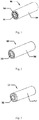
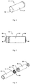
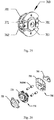
- the universal rechargeable battery constituted by employing lithium-ion battery includes: an outer packaging housing; and a charging/discharging controller, a positive electrode crimping piece, a lithium-ion battery, and a negative electrode end cap that are successively press assembled in the outer packaging housing
- the charging/discharging controller includes a charging/discharging controller housing, and a charging/discharging control circuit solder body, an insulating washer and a charging/discharging controller support frame provided in the charging/discharging controller housing
- the charging/discharging control circuit solder body is soldered with a lithium-ion battery charging/discharging control circuit including: a lithium-ion battery charging control circuit, a lithium-ion battery detection circuit and a DC-DC step-down regulator discharging circuit soldered on a circuit substrate respectively, the circuit substrate is electrically connected to the lithium-ion battery and a positive electrode end cap respectively, and the circuit substrate is electrically connected to the negative electrode end cap via the charging/discharging controller housing
- the lithium-ion battery charging/discharging control circuit detects an output voltage of the lithium-ion battery and selects a charging scheme of trickling charge, constant-current charge or constant-voltage charge to charge the lithium-ion battery according to the output voltage of the lithium-ion battery; and during a discharging status, the lithium-ion battery charging/discharging control circuit detects the output voltage of the lithium-ion battery, and performs a regulated voltage output by: decreasing the output voltage of the lithium-ion battery to a first output voltage when the output voltage of the lithium-ion battery is greater than a low power voltage VL; decreasing the output voltage of the lithium-ion battery to a second output voltage when the output voltage of the lithium-ion battery is equal to or lower than the low power voltage VL; and cutoffing the regulated voltage output when the output voltage of the lithium-ion battery drops to be equal to or lower than the discharge cutoff voltage VD; wherein VL is a preset low power voltage of the
- the lithium-ion battery charging/discharging control circuit detects a temperature of the lithium-ion battery, and controls the lithium-ion battery charging control circuit to stop charging of the lithium-ion battery when the temperature of the lithium-ion battery raises to a charging upper threshold temperature and restores the charging of the lithium-ion battery again when the temperature of the lithium-ion battery decreases to a value of subtracting a backlash temperature from the charging upper threshold temperature; and during the discharging status, the lithium-ion battery charging/discharging control circuit detects a temperature of the lithium-ion battery, and controls the DC-DC step-down regulator discharging circuit to stop discharging of the lithium-ion battery when the temperature of the lithium-ion battery raises to a discharging upper threshold temperature and restores the discharging of the lithium-ion battery again when the temperature of the lithium-ion battery decreases to a value of subtracting a backlash temperature from the discharging upper threshold temperature.
- the lithium-ion battery charging/discharging control circuit detects a maximum threshold output current of the charging power source, and charges the lithium-ion battery at the maximum threshold output current of the charging power source when the maximum threshold output current of the charging power source is smaller than a preset charging current value.
- the first output voltage is preferably 1.5V
- the second output voltage is preferably1.1V.
- the method for controlling the universal rechargeable battery includes the following control conditions:
- Another object of the invention is to improve a universal rechargeable battery known from the state of the art.
- an object of the present disclosure is to provide a universal rechargeable battery constituted by employing lithium-ion battery which has a regulated voltage output of 1.5V and a regulated voltage output during low power of the lithium-ion battery of 1.1V, may be charged by using a computer USB interface or a universal lithium-ion battery charging adapter, has a shaping structure and discharge characteristics satisfying technical specifications of GB/T 8897.2-2013 and IEC 60086-2, and may be used as direct substitutes for known universal primary batteries and Ni-H rechargeable batteries.
- the battery has a high performance, and has a simple charging/discharging controller structure and a simple assembling process, which may facilitate the automatic mass production.
- a charging/discharging controller housing is used as the electrode structure for connecting the negative electrode of the lithium-ion battery into the charging/discharging control circuit of the lithium-ion battery, a significant inner space of the charging/discharging controller may be saved and a moveable part obstructing the sealing of the charging/discharging controller may be eliminated, and thus waterproof sealing thereof may be realized and a problem of circuit failure after getting wet may be prevented. Meanwhile, it may facilitate improving power capacity of the universal rechargeable battery and lowering the manufacturing cost.
- a charging/discharging control circuit is provided in the charging/discharging controller, thereby controlling and protecting the charging/discharging process of the lithium-ion battery, and improving cycle life and safety of the lithium-ion battery.
- the present disclosure provides a universal rechargeable battery constituted by employing a lithium-ion battery, including: an outer packaging housing, and a charging/discharging controller, a positive electrode crimping piece, a lithium-ion battery, and a negative electrode end cap that are successively press assembled in the outer packaging housing, wherein the charging/discharging controller includes: a charging/discharging controller housing, and a charging/discharging control circuit solder body, an insulating washer and a charging/discharging controller support frame provided in the charging/discharging controller housing, wherein the charging/discharging control circuit solder body is soldered with a lithium-ion battery charging/discharging control circuit including: a lithium-ion battery charging control circuit, a lithium-ion battery detection circuit and a DC-DC step-down regulator discharging circuit soldered on a circuit substrate respectively, the circuit substrate is electrically connected to the lithium-ion battery and a
- the positive electrode end cap is provided at an end of the charging/discharging controller and has a positive electrode contact point exposed outside the outer packaging housing, and the positive electrode contact point is used as a positive electrode of the universal rechargeable battery; and a negative electrode contact point exposed outside the outer packaging housing is provided at an end of the negative electrode end cap, and the negative electrode contact point is used as a negative electrode of the universal rechargeable battery.
- the lithium-ion battery is a negative electrode outer housing packaging lithium-ion battery unit, a positive electrode outer housing packaging lithium-ion battery unit, or a soft packaging lithium-ion battery unit;
- the universal rechargeable battery is a R6 rechargeable battery, a R03 rechargeable battery, a R1 rechargeable battery or a R8D425 rechargeable battery; and the universal rechargeable battery employs a computer USB interface or a universal lithium-ion battery charging adapter as a charging power source to charge the universal rechargeable battery.
- the positive electrode crimping piece is formed with a metal material having high elastic recovery, high thermal conductivity and high electrical conductivity undergoing a conductive anti-oxidation treatment at a surface thereof; each of the positive electrode end cap, the outer packaging housing, the negative electrode end cap, and the charging/discharging controller housing is formed with a metal material having high thermal conductivity and high electrical conductivity undergoing a conductive anti-oxidation treatment at a surface thereof; and the charging/discharging controller support frame is made of a light transmitting insulation material, is used for mounting the charging/discharging control circuit solder body, and is used for transmitting a light signal emitted from a light emitting diode indicating charging status of the universal rechargeable battery outside the universal rechargeable battery.
- a structure of the charging/discharging controller is constituted by: assembling the charging/discharging controller support frame, the charging/discharging control circuit solder body and the insulating washer inside the charging/discharging controller housing, and soldering a bead of the charging/discharging controller housing to a copper coated portion of a V- terminal of the lithium-ion battery charging/discharging control circuit of a PCB2 circuit substrate after bead-sealing the charging/discharging controller housing; and wherein a structure of the lithium-ion battery charging/discharging control circuit soldered in the charging/discharging control circuit solder body is constituted by: soldering a PCB1 circuit substrate soldered with elements of the lithium-ion battery charging/discharging control circuit and the PCB2 circuit substrate together with connection pins, and soldering the positive electrode end cap on the PCB1 circuit substrate and soldering the positive electrode crimping piece on the PCB2 circuit substrate, wherein the connection pins are formed
- the universal rechargeable battery constituted by employing lithium-ion battery according to the present disclosure has a regulated voltage output of 1.5V and a regulated voltage output during low power of the lithium-ion battery of 1.1V
- the universal rechargeable battery may be charged using a computer USB interface or a universal lithium-ion battery charging adaptor, and has a shaping structure and discharge characteristics satisfying technical specifications of GB/T 8897.2-2013 and IEC 60086-2, therefore may be used as direct substitutes for known universal primary batteries and Ni-H rechargeable batteries.
- the battery has a simple charging/discharging controller structure and a simple assembling process, which may facilitate the automatic mass production.
- a charging/discharging controller housing is used as the electrode structure for connecting the negative electrode of the lithium-ion battery into the lithium-ion battery charging/discharging control circuit, a significant inner space of the charging/discharging controller may be saved and a moveable part obstructing the sealing of the charging/discharging controller may be eliminated, and thus waterproof sealing thereof may be realized and a problem of circuit failure after getting wet may be prevented. Meanwhile, it may facilitate improving power capacity of the universal rechargeable battery and lowering the manufacturing cost.
- a lithium-ion battery charging/discharging control circuit is provided in the charging/discharging controller, thereby controlling and protecting the charging/discharging process of the lithium-ion battery, and improving cycle life and safety of the lithium-ion battery.
- the charging/discharging control circuit charging/discharging process of the lithium-ion battery may be controlled and protected; charging mode, charging rate, overcharge, overdischarge, discharging rate and discharging overheat during the process of the charging/discharging of the lithium-ion battery may be controlled and protected; cycle life and safety of the lithium-ion battery may be improved; the universal rechargeable battery may have a regulated voltage output of 1.5V and a regulated voltage output during low power of the lithium-ion battery of 1.1V, and the universal rechargeable battery may be charged using a computer USB interface or a universal lithium-ion battery charging adaptor, and has a shaping structure and discharge characteristics satisfying technical specifications of GB/T 8897.2-2013 and IEC 60086-2, therefore may be used as direct substitutes for known universal primary batteries and Ni-
- the present disclosure provides a universal rechargeable battery constituted by employing lithium-ion battery, wherein the rechargeable battery includes: an outer packaging housing and a charging/discharging controller, a positive electrode crimping piece, a lithium-ion battery and a negative electrode end cap that are successively press assembled in the outer packaging housing.
- the charging/discharging controller is provided at an end thereof with a positive electrode end cap having a positive electrode contact point exposed outside the outer packaging housing, and the positive electrode contact point is used as a positive electrode of the universal rechargeable battery.
- An end of the negative electrode end cap is provided with a negative electrode contact point exposed outside the outer packaging housing, and the negative electrode contact point is used as a negative electrode of the universal rechargeable battery.
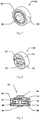
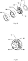
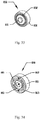
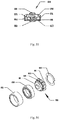
- the charging/discharging controller 550 (750, 850, 950) includes: a charging/discharging controller housing 551 (751, 851, 951) and a charging/discharging control circuit solder body 560 (760, 860, 960), a charging/discharging controller support frame 552 (752, 852, 952), and an insulating washer 563 (763, 863, 963) provided in the charging/discharging controller housing 551 (751, 851, 951).
- the charging/discharging control circuit solder body 560 (760, 860, 960) is soldered with a lithium-ion battery charging/discharging control circuit.
- the charging/discharging controller 550 has a structure satisfying technical specifications for a R6 rechargeable battery
- the charging/discharging controller 750 has a structure satisfying technical specifications for a R03 rechargeable battery
- the charging/discharging controller 850 has a structure satisfying technical specifications for a R1 rechargeable battery
- the charging/discharging controller 950 has a structure satisfying technical specifications for a R8D425 rechargeable battery.
- the charging/discharging controller is constituted by assembling the charging/discharging controller support frame, the charging/discharging control circuit solder body and the insulating washer in the charging/discharging controller housing, and soldering a bead of the charging/discharging controller housing to a copper coated portion of a V- terminal of the lithium-ion battery charging/discharging control circuit of the PCB2 circuit substrate after bead-sealing the charging/discharging controller housing.
- Structure of lithium-ion battery charging/discharging control circuit soldered in the charging/discharging control circuit solder body it is constituted by soldering the PCB1 circuit substrate soldered with elements of the lithium-ion battery charging/discharging control circuit and the PCB2 circuit substrate together with connection pins, and soldering the positive electrode end cap on the PCB1 circuit substrate and soldering the positive electrode crimping piece on the PCB2 circuit substrate.
- the connection pins are formed of metal material having high thermal conductivity and high electrical conductivity.
- the charging/discharging control circuit solder body 560 (760, 860, 960) is assembled by following steps: step 1, soldering elements of the lithium-ion battery charging/discharging control circuit other than a thermistor Rt on both sides of a PCB1 circuit substrate 571 (771, 871, 971) and constituting a PCB1 solder body 570 (770, 870, 970); step 2, soldering the thermistor Rt on the front side of a PCB2 circuit substrate 581 (781, 881, 981) and constituting a PCB2 solder body 580 (780, 880, 980); step 3, soldering the PCB1 solder body 570 (770, 870, 970) and the PCB2 solder body 580 (780, 880, 980) by inter board connection pin 562 (762, 862, 962); step 4, soldering a positive electrode end cap 501 (701, 801, 901) at a copper coated portion of a V+ terminal of the lithium-i
- the charging/discharging controller 550 (750, 850, 950) is assembled by following steps: step 1, assembling the charging/discharging controller support frame 552 (752, 852, 952) into the charging/discharging controller housing 551 (751, 851, 951); step 2, assembling the charging/discharging control circuit solder body 560 (760, 860, 960) and the insulating washer 563 (763, 863, 963) into the charging/discharging controller support frame 552 (752, 852, 952); step 3, bead-sealing the charging/discharging controller housing 551 (751, 851, 951) using a beading machine; step 4, soldering a bead of the beaded charging/discharging controller housing 551 (751, 851, 951) with a copper coated portion of a V- terminal of the lithium-ion battery charging/discharging control circuit of the PCB2 circuit substrate 581 (781, 881, 981); and step 5, injecting packaging adhesive via an injection hole of the PCB2
- the charging/discharging controller housing 551 (751, 851, 951) is a connecting electrode of the V- terminal of the lithium-ion battery charging/discharging control circuit
- the positive electrode end cap 501 (701, 801, 901) is a connecting electrode of the V+ terminal of the lithium-ion battery charging/discharging control circuit
- the positive electrode crimping piece 561 (761, 861, 961) is a connecting electrode of the node Jb+ (as illustrated in Fig. 54 ) of the lithium-ion battery charging/discharging control circuit.
- the charging/discharging controller support frame 552 (752, 852, 952) is made of a light transmitting insulation material, is used for mounting the charging/discharging control circuit solder body 560 (760, 860, 960), and is used for transmitting a light signal emitted from a light emitting diode D1 indicating charging status of the universal rechargeable battery outside the universal rechargeable battery, thereby displaying the charging status of the universal rechargeable battery.
- the lithium-ion battery is selected from a negative electrode outer housing packaging lithium-ion battery unit, a positive electrode outer housing packaging lithium-ion battery unit or a soft packaging lithium-ion battery unit.
- Assembling the universal rechargeable battery using the lithium-ion battery unit includes the following steps: step 1, soldering the negative electrode end cap to the negative electrode of the lithium-ion battery using a spot welder; step 2, after accommodating the charging/discharging controller, the lithium-ion battery unit and the negative electrode end cap into the outer packaging housing along an axis direction and positioning and fixing the same at an insulation position of a beading machine, bead-sealing the outer packaging housing to complete the assembling of the universal rechargeable battery; and step 3, coating or applying an insulation and finishing material outside outer packaging housing of the assembled universal rechargeable battery to constitute the finished universal rechargeable battery.
- Embodiments employing such an assembling means include: a R6 rechargeable battery constituted by employing a negative electrode outer housing packaging lithium-ion battery unit, a R03 rechargeable battery constituted by employing a positive electrode outer housing packaging lithium-ion battery unit, and a R1 rechargeable battery constituted by employing a negative electrode outer housing packaging lithium-ion battery unit.
- each of the positive electrode end cap, the outer packaging housing, the negative electrode end cap, the charging/discharging controller housing and the connecting pin is formed with a metal material having high thermal conductivity and high electrical conductivity undergoing a conductive anti-oxidation treatment at a surface thereof.
- a molding process of the outer packaging housing is a prefabrication thin-wall tubular material molding, a sheet material drum molding or a sheet material rolling molding.
- a molding process of the charging/discharging controller housing is a prefabrication thin-wall tubular material molding, a sheet material drum molding or a sheet material rolling molding.
- the positive electrode crimping piece is formed with a metal material having high elastic recovery, high thermal conductivity and high electrical conductivity undergoing a conductive anti-oxidation treatment at a surface thereof.
- the PCB1 circuit substrate and the PCB2 circuit substrate are formed with insulating material having a relative higher thermal conductively and may dissipate heat by transferring heat generated by the lithium-ion battery and the elements to the outer packaging housing.
- heat generated by the power devices of the lithium-ion battery charging/discharging control circuit is dissipated by transmitting the same to the outer packaging housing of the universal rechargeable battery via the PCB1 circuit substrate, the PCB2 circuit substrate, copper coating heat conducting structures of the circuit, and the charging/discharging controller housing.
- Heat generated by the lithium-ion battery is dissipated, at the positive electrode end of the lithium-ion battery, by transmitting the same to the outer packaging housing of the universal rechargeable battery via the positive electrode crimping piece, the PCB circuit substrates (PCB1 and PCB2), copper coating heat conducting structures of the circuit, and the charging/discharging controller housing.
- Heat generated by the lithium-ion battery is dissipated, at the negative electrode end of the lithium-ion battery, by transmitting the same to the outer packaging housing of the universal rechargeable battery via the negative electrode end cap.
- the charging/discharging control circuit solder body is soldered with a lithium-ion battery charging/discharging control circuit including a lithium-ion battery charging control circuit, a lithium-ion battery detection circuit and a DC-DC step-down regulator discharging circuit soldered on the circuit substrate respectively, and the circuit substrate is electrically connected to the lithium-ion battery and the positive electrode end cap respectively, and the circuit substrate is electrically connected to the negative electrode end cap via the charging/discharging controller housing and the outer packaging housing.
- the universal rechargeable battery of the present disclosure is charged with a computer USB interface or a universal lithium-ion battery charging adapter.
- the DC-DC step-down regulator discharging circuit is controlled to cutoff the regulated voltage output, and the lithium-ion battery charging control circuit is controlled to perform charging of the lithium-ion battery.
- the lithium-ion battery charging/discharging control circuit of the universal rechargeable battery constituted by employing lithium-ion battery of the present disclosure has a charging status in connection with the charging power source and a discharging status disconnected from the charging power source.
- a charging/discharging control method of the universal rechargeable battery includes the flowing control conditions.
- Control condition 1 after the charging power source is connected to the universal rechargeable battery, the lithium-ion battery charging/discharging control circuit performs the charging status upon detection of the charging power source connection. During the charging status, the lithium-ion battery charging/discharging control circuit cutoffs the regulated discharge voltage output and performs charging of the lithium-ion battery.
- the lithium-ion battery charging/discharging control circuit detects an output voltage of the lithium-ion battery and selects a charging scheme of trickling charge, constant-current charge or constant-voltage charge to charge the lithium-ion battery according to the output voltage of the lithium-ion battery.
- the lithium-ion battery charging control circuit detects a maximum threshold output current of the charging power source, and charges the lithium-ion battery at the maximum threshold output current of the charging power source when the maximum threshold output current of the charging power source is smaller than a preset charging current value.
- a charging current during the constant-voltage charge is decreased to a preset fully charged determination current, charging of the lithium-ion battery is stopped.
- Control condition 3 when the charging power source is disconnected from the universal rechargeable battery, the lithium-ion battery charging/discharging control circuit detects the disconnection of the charging power source, and discharges remaining power stored in the filter capacitor during the charging, such that a voltage across the positive electrode and the negative electrode of the universal rechargeable battery drops rapidly to be equal to or lower than the maximum open circuit voltage and a discharging status is performed. During the discharging status, the lithium-ion battery charging/discharging control circuit cutoffs the charging and performs a regulated voltage discharge, and performs a regulated voltage output according to control condition 4.
- Control condition 4 during the discharging status, the lithium-ion battery charging/discharging control circuit detects the output voltage of the lithium-ion battery, and performs a regulated voltage output by: decreasing the output voltage of the lithium-ion battery to a first output voltage when the output voltage of the lithium-ion battery is greater than a low power voltage V L ; decreasing the output voltage of the lithium-ion battery to a second output voltage when the output voltage of the lithium-ion battery is greater than a discharge cutoff voltage V D while equal to or lower than the low power voltage V L , and restoring the output of the lithium-ion battery to the first voltage when the output voltage of the charged lithium-ion battery is greater than V L + ⁇ V 1 , wherein V L is a low power voltage of the lithium-ion battery set by the voltage detection circuit based on the voltage/capacity characteristics of the lithium-ion battery for the universal rechargeable battery, ⁇ V 1 is a backlash voltage of the lower power voltage detection threshold of the lithium-ion battery set by the voltage
- Control condition 5 during the discharging status, the lithium-ion battery charging/discharging control circuit detects the output voltage of the lithium-ion battery, and cutoffs the regulated voltage output when the output voltage of the lithium-ion battery drops to be equal to or lower than the discharge cutoff voltage V D and restores the regulated voltage output according to control condition 4 when the output voltage of the charged lithium-ion battery is greater than V D + ⁇ V 2 , wherein ⁇ V 2 is a backlash voltage of the discharge cutoff voltage detection threshold of the lithium-ion battery set by the voltage detection circuit.
- the lithium-ion battery charging/discharging control circuit detects the temperature of the lithium-ion battery, and cutoffs the charging of the lithium-ion battery when the temperature of the lithium-ion battery raises to a charging upper threshold temperature T CH and restores the charging of the lithium-ion battery when the temperature of the lithium-ion battery decreases to be lower than a temperature obtained by subtracting a backlash temperature form the charging upper threshold temperature, i.e., T CH - ⁇ T 1 , wherein T CH is a charging upper threshold temperature of the lithium-ion battery set based on the charging technical specifications of the lithium-ion battery for the universal rechargeable battery, and ⁇ T 1 is a backlash temperature corresponding to a backlash voltage of the T CH detection threshold set by a voltage detection circuit of the thermistor Rt.
- the lithium-ion battery charging/discharging control circuit detects the temperature of the lithium-ion battery, and cutoffs the regulated voltage output when the temperature of the lithium-ion battery raises to a discharging upper threshold temperature T DH and restores the regulated voltage output when the temperature of the lithium-ion battery decreases to be lower than a temperature obtained by subtracting a backlash temperature form the discharging upper threshold temperature, i.e., T DH - ⁇ T 2 , wherein T DH is a discharging upper threshold temperature of the lithium-ion battery set based on the discharging technical specifications of the lithium-ion battery for the universal rechargeable battery, and ⁇ T 2 is a backlash temperature corresponding to a backlash voltage of the T DH detection threshold set by a voltage detection circuit of the thermistor Rt.
- the lithium-ion battery is charged according to control condition 2 when control condition 1 determines that the charging power source is connected to the universal rechargeable battery and control condition 6 allows for the charging of the lithium-ion battery, and the charging of the lithium-ion battery is cutoff when control condition 6 prohibits the charging of the lithium-ion battery.
- Output power of the lithium-ion battery is stepped-down and regulated output according to control condition 4 when control condition 3 determines that the universal rechargeable battery is disconnected from the charging power source and both control condition 5 and control condition 7 allow for the discharging output of the lithium-ion battery, and the lithium-ion battery charging/discharging control circuit cutoffs the regulated voltage output when either one of control condition 5 and control condition 7 prohibits the discharging output of the lithium-ion battery.
- the first output voltage of the universal rechargeable battery provided in the present disclosure may be any voltage value from 1.35V to 1.725V
- the second output voltage may be any voltage value from 0.9V to 1.35V
- the maximum open circuit voltage may be any voltage value from 1.5V to 1.725V.
- the first output voltage is 1.5V
- the second output voltage is 1.1V
- the maximum open circuit voltage is 1.65V.
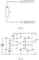
- the lithium-ion battery charging/discharging control circuit includes: a lithium-ion battery LIB, a monolithic integration rechargeable battery control chip U1, a negative temperature coefficient (NTC) thermistor Rt, a first resistor R1, a second resistor R2, a third resistor R3, a fourth resistor R4, a fifth resistor R5, a light emitting diode D1, a first capacitor C1, a second capacitor C2, and an inductor L1, wherein the monolithic integration rechargeable battery control chip U1, the light emitting diode D1, the third resistor R3, the fourth resistor R4, the first capacitor C1 and the second capacitor C2 constitute the lithium-ion battery charging control circuit, the monolithic integration rechargeable battery control chip U1, the first resistor R1, the second resistor R2, the fifth resistor R5 and the NTC thermistor Rt constitute the lithium-ion battery detection circuit, and the monolithic integration rechargeable battery control chip U1, the inductor L1, the first
- the positive electrode of the lithium-ion battery LIB is connected to the node Jb+, and the negative electrode of the lithium-ion battery LIB is connected to the V-terminal of the lithium-ion battery charging/discharging control circuit.
- a charging power source connection lead VCC of the monolithic integration rechargeable battery control chip U1 is connected to the V+ terminal of the lithium-ion battery charging/discharging control circuit
- a lithium-ion battery connection lead BAT of the monolithic integration rechargeable battery control chip U1 is connected to the cathode of the lithium-ion battery LIB
- a power source grounding lead GND of the monolithic integration rechargeable battery control chip U1 is connected to the negative electrode of the lithium-ion battery LIB and the V- terminal of the lithium-ion battery charging/discharging control circuit
- a charging status outputting lead LDD of the monolithic integration rechargeable battery control chip U1 is connected to a cathode of the light emitting diode D1, a temperature detection setting lead DT
- the NTC thermistor Rt is a NTC thermistor for sensing the temperature of the lithium-ion battery LIB, an end of the NTC thermistor Rt is connected to the second resistor R2 and the NTC voltage detection lead NTC of the monolithic integration rechargeable battery control chip U1 at the voltage division node P2, the other end thereof is connected to the power source grounding lead GND of the monolithic integration rechargeable battery control chip U1, and an insulation part of the body of the NTC thermistor Rt is attached to a thermal conductive circuit structure connected to the output electrode of the lithium-ion battery LIB.
- the first resistor R1 is an upper biasing voltage division resistor at the voltage division node P2, an end of the first resistor R1 is connected to the positive electrode of the lithium-ion battery LIB, and the other end thereof is connected to the second resistor R2 and the temperature detection setting lead DTCS of the monolithic integration rechargeable battery control chip U1 at the node P1.
- the second resistor R2 is an upper biasing voltage division resistor at the voltage division node P2, an end of the second resistor R2 is connected to the first resistor R1 and the temperature detection setting lead DTCS of the monolithic integration rechargeable battery control chip U1 at the node P1, and the other end thereof is connected to the NTC thermistor Rt and the NTC voltage detection lead NTC of the monolithic integration rechargeable battery control chip U1 at the voltage division node P2.
- the third resistor R3 is a current limiting resistor of the light emitting diode D1, an end of the third resistor R3 is connected to the V+ terminal of the lithium-ion battery charging/discharging control circuit, and the other end thereof is connected to the anode of the light emitting diode D1.
- the fourth resistor R4 is a charging current setting resistor of the monolithic integration rechargeable battery control chip U1, an end of the fourth resistor R4 is connected to the charging current setting lead IBSET of the monolithic integration rechargeable battery control chip U1, and the other end thereof is connected to the power source grounding lead GND of the monolithic integration rechargeable battery control chip U1.
- the fifth resistor R5 is a remaining power discharging current limiting resistor of the second capacitor C2, an end of the fifth resistor R5 is connected to the remaining power discharging lead DECO of the monolithic integration rechargeable battery control chip U1, and the other end thereof is connected to the positive electrode of the second capacitor C2.
- the light emitting diode D1 is a charging operation status indicting light emitting diode of the monolithic integration rechargeable battery control chip U1, the anode of the light emitting diode D1 is connected to the other end of the third resistor R3, and the cathode thereof is connected to the charging status outputting lead LDD of the monolithic integration rechargeable battery control chip U1.
- the first capacitor C1 is a charging output filter and discharging input filter and compensation capacitor of the monolithic integration rechargeable battery control chip U1
- the positive electrode of the first capacitor C1 is connected to the lithium-ion battery connection lead BAT of the monolithic integration rechargeable battery control chip U1
- the negative electrode thereof is connected to the power source grounding lead GND of the monolithic integration rechargeable battery control chip U1.
- the second capacitor C2 is a charging input filter and discharging output filter and compensation capacitor of the monolithic integration rechargeable battery control chip U1
- the positive electrode of the second capacitor C2 is connected to the other end of the inductor L1
- the charging power source connection lead VCC of the monolithic integration rechargeable battery control chip U1 and the V+ terminal of the lithium-ion battery charging/discharging control circuit, and the negative electrode thereof is connected to the power source grounding lead GND of the monolithic integration rechargeable battery control chip U1.
- the inductor L1 is an output filter and compensation inductor of the monolithic integration rechargeable battery control chip U1, an end of the inductor L1 is connected to the modulated output lead SW of the monolithic integration rechargeable battery control chip U1, and the other end thereof is connected to the positive electrode of the second capacitor C2 and the V+ terminal of the lithium-ion battery charging/discharging control circuit.
- the monolithic integration rechargeable battery control chip U1 may be MGS4520A, MGS4520B or MGS4520C from ShenZhen Migison Electric Co., Ltd, having main control parameters as follows: input voltage 2.25V to 6V, charging upper threshold voltage V H (4.2V for MGS4520A, 3.65V for MGS4520B and 4.35V for MGS4520C), constant-current charging current (I CHG ) 500mA, fully charged determination current I CHG /10, NTC voltage detection threshold 0.3V LIB , discharge cutoff voltage V D (3.0V for MGS4520A, 2.5V for MGS4520B, and 3.0V for MGS4520C), discharging low power voltage V L (3.4V for MGS4520A, 3.1V for MGS4520B, and 3.4V for MGS4520C), remaining power discharging threshold 1.65V, steady state output voltage 1.5V (1.1V when V LIB ⁇ V L ), and maximum steady state output current 2A (1.0A when I OSET
- a method for controlling a switch of charging/discharging modes is provided.
- a voltage of the charging power source connection lead VCC of the monolithic integration rechargeable battery control chip U1 is lower than 4V, the monolithic integration rechargeable battery control chip U1 cutoffs the charging and performs a regulated voltage output, and the universal rechargeable battery is in a regulated voltage output status.
- the monolithic integration rechargeable battery control chip U1 After the charging power source is connected, when the voltage of the charging power source connection lead VCC of the monolithic integration rechargeable battery control chip U1 is higher than 4V, the monolithic integration rechargeable battery control chip U1 cutoffs the regulated voltage output and performs the charging of the lithium-ion battery LIB, and the universal rechargeable battery is in a charging status until the charging power source is powered off when it is switched to discharging status and the discharge output is restored.
- the remaining power discharging lead DECO of the monolithic integration rechargeable battery control chip U1 outputs a low level, and the remaining power charged in the second capacitor C2 during the charging is current limitedly discharged via the fifth resistor R5, such that the idle voltage of the universal rechargeable battery drops rapidly to the maximum open circuit voltage.
- the output of the remaining power discharging lead DECO of the monolithic integration rechargeable battery control chip U1 switches to a high impedance state.
- a control method for a charging process is provided. After the charging power source is connected to the universal rechargeable battery, the positive electrode of the charging power source is connected to the positive electrode V+ of the universal rechargeable battery, and the negative electrode of the charging power source is connected to the negative electrode V- of the universal rechargeable battery.
- the positive electrode V+ of the universal rechargeable battery is a V+ terminal of the lithium-ion battery charging/discharging control circuit and the negative electrode V- of the universal rechargeable battery is the V- terminal of the lithium-ion battery charging/discharging control circuit
- it corresponds to connecting the positive electrode of the charging power source to the charging power source connection lead VCC of the monolithic integration rechargeable battery control chip U1 and connecting the negative electrode of the charging power source to the power source grounding lead GND of the monolithic integration rechargeable battery control chip U1.
- the monolithic integration rechargeable battery control chip U1 performs the charging of the lithium-ion battery LIB.
- the monolithic integration rechargeable battery control chip U1 detects the output voltage V LIB of the lithium-ion battery LIB via the lithium-ion battery connection lead BAT, and charges the lithium-ion battery LIB with the output of the lithium-ion battery connection lead BAT according to the status of V LIB .
- a method for controlling the charging current is provided.
- a method for adaptively controlling the output current of the charging power source is provided.
- the monolithic integration rechargeable battery control chip U1 detects magnitude value of the voltage drop between an output voltage of the charging power source in the idle status and an output voltage of the charging power source in the linearly loaded status via the charging power source connection lead VCC, and determines the maximum allowed output current of the charging power source. When the maximum allowed output current of the charging power source is smaller than the current I CHG , the monolithic integration rechargeable battery control chip U1 charges the lithium-ion battery LIB with the maximum allowed output current of the charging power source as the current limitation.
- a method for controlling the regulated voltage output is provided.
- the monolithic integration rechargeable battery control chip U1 detects the output voltage V LIB of the lithium-ion battery LIB via the lithium-ion battery connection lead BAT.
- the monolithic integration rechargeable battery control chip U1 steps down the output voltage V LIB of the lithium-ion battery LIB to 1.5V for a regulated voltage output.
- the monolithic integration rechargeable battery control chip U1 steps down the output voltage V LIB of the lithium-ion battery LIB to 1.1V for a regulated voltage output.
- a determination value of the monolithic integration rechargeable battery control chip U1 for the detection of the low power voltage V L of the lithium-ion battery LIB is a multi-point sampling average value having a sampling frequency proportional to an output voltage change ratio of the lithium-ion battery LIB.
- the backlash voltage of the detection threshold is ⁇ V 1 , thus the monolithic integration rechargeable battery control chip U1 restores the regulated voltage output of 1.5V after the voltage V LIB of the charged lithium-ion battery LIB is raised to be equal to or greater than V L + ⁇ V 1 .
- a method for overdischarge protection is provided.
- the monolithic integration rechargeable battery control chip U1 detects the output voltage V LIB of the lithium-ion battery LIB via the lithium-ion battery connection lead BAT.
- the monolithic integration rechargeable battery control chip U1 performs the regulated voltage output.
- the output voltage V LIB of the lithium-ion battery LIB is equal to or smaller than the discharge cutoff voltage (V LIB ⁇ V D )
- the monolithic integration rechargeable battery control chip U1 cutoffs the regulated voltage output.
- a determination value of the monolithic integration rechargeable battery control chip U1 for the detection of the discharge cutoff voltage V D of the lithium-ion battery LIB is a multi-point sampling average value having a sampling frequency proportional to an output voltage change ratio of the lithium-ion battery LIB.
- the backlash voltage of the detection threshold is ⁇ V 2 , thus the monolithic integration rechargeable battery control chip U1 restores the regulated voltage output after the output voltage V LIB of the charged lithium-ion battery LIB is raised to be equal to or greater than V D + ⁇ V 2 .
- a control for controlling output overload or short circuit is provided.
- the monolithic integration rechargeable battery control chip U1 is configured with an output overload protection circuit having a settable current limitation.
- the monolithic integration rechargeable battery control chip U1 performs a regulated voltage output with a current limitation at a preset maximum output current I LIM .
- the current limitation for the regulated voltage output of the monolithic integration rechargeable battery control chip U1 is set according to the input level of the discharging current setting lead I OSET of the monolithic integration rechargeable battery control chip U1.
- the monolithic integration rechargeable battery control chip U1 When the discharging current setting lead I OSET of the monolithic integration rechargeable battery control chip U1 is connected to the lithium-ion battery connection lead BAT of the monolithic integration rechargeable battery control chip U1, the monolithic integration rechargeable battery control chip U1 has a maximum output current I LIM of 2A. When the discharging current setting lead I OSET of the monolithic integration rechargeable battery control chip U1 is connected to the power source grounding lead GND of the monolithic integration rechargeable battery control chip U1, the monolithic integration rechargeable battery control chip U1 has a maximum output current I LIM of 1A.
- the maximum output current I LIM of the monolithic integration rechargeable battery control chip U1 is configured according to the discharging rate characteristics of the lithium-ion battery for the universal rechargeable battery, thereby preventing an over-rate discharging damage to the lithium-ion battery LIB when the universal rechargeable battery is overloaded or shout circuited.
- the NTC voltage detection lead NTC of the monolithic integration rechargeable battery control chip U1 has a threshold voltage of 0.3V LIB .
- the NTC voltage detection lead NTC of the monolithic integration rechargeable battery control chip U1 When the operating temperature of the lithium-ion battery LIB is lower than the preset charging upper threshold temperature T CH , the NTC voltage detection lead NTC of the monolithic integration rechargeable battery control chip U1 has a voltage higher than 0.3V LIB , and the monolithic integration rechargeable battery control chip U1 performs the charging of the lithium-ion battery LIB.
- the NTC voltage detection lead NTC of the monolithic integration rechargeable battery control chip U1 has a voltage equal to or lower than 0.3V LIB , and the monolithic integration rechargeable battery control chip U1 cutoffs the charging of the lithium-ion battery LIB.
- a backlash voltage of the NTC voltage detection threshold of the monolithic integration rechargeable battery control chip U1 is ⁇ V T , and thus when the operating temperature of the lithium-ion battery LIB decreases such that the NTC voltage detection lead NTC of the monolithic integration rechargeable battery control chip U1 has a voltage equal to or lower than 0.3V LIB + ⁇ V T , the monolithic integration rechargeable battery control chip U1 restores the charging of the lithium-ion battery LIB.
- the NTC voltage detection lead NTC of the monolithic integration rechargeable battery control chip U1 has a threshold voltage of 0.3V LIB .
- the NTC voltage detection lead NTC of the monolithic integration rechargeable battery control chip U1 When the operating temperature of the lithium-ion battery LIB is lower than the discharging upper threshold temperature T DH , the NTC voltage detection lead NTC of the monolithic integration rechargeable battery control chip U1 has a voltage higher than 0.3V LIB , and the monolithic integration rechargeable battery control chip U1 performs the regulated voltage output.
- the NTC voltage detection lead NTC of the monolithic integration rechargeable battery control chip U1 has a voltage equal to or lower than 0.3V LIB , and the monolithic integration rechargeable battery control chip U1 cutoffs the regulated voltage output.
- a backlash voltage of the NTC voltage detection threshold of the monolithic integration rechargeable battery control chip U1 is ⁇ V T , and thus when the lithium-ion battery LIB stops discharging and the operating temperature of the lithium-ion battery LIB decreases such that the NTC voltage detection lead NTC of the monolithic integration rechargeable battery control chip U1 has a voltage equal to or lower than 0.3V LIB + ⁇ V T , the monolithic integration rechargeable battery control chip U1 restores the regulated voltage output.
- a constructing method and a circuit connecting method of the constituted universal rechargeable batteries of the R6 rechargeable battery 500, the R03 rechargeable battery 700, the R1 rechargeable battery 800 and the R8D425 rechargeable battery 900, under the corresponding shaping structural technical standards and the structural technical specifications of the charging/discharging controller, are described as follows.
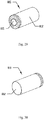
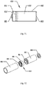
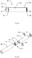
- the R6 rechargeable battery 500 includes: an outer packaging housing 502; and a charging/discharging controller 550, a lithium-ion battery 510, and a negative electrode end cap 503 packaged in the outer packaging housing 502.
- a protrusion structure of the positive electrode end cap 501 exposed outside the outer packaging housing 502 is used as the positive electrode of the R6 rechargeable battery 500.
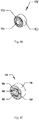
- a light transmitting flange structure of the charging/discharging controller support frame 552 formed of light transmitting insulation material between the positive electrode end cap 501 and the outer packaging housing 502 is used as a light emitting display for the charging operating status of the R6 rechargeable battery 500.
- a protrusion structure of the negative electrode end cap 503 exposed outside the outer packaging housing 502 is used as the negative electrode of the R6 rechargeable battery 500.
- a circular outer housing and a bottom end of the negative electrode outer housing packaging lithium-ion battery unit 510 are the negative electrode 512 of the lithium-ion battery unit 510, and a protrusion cap at the other end is the positive electrode 511 of the lithium-ion battery unit 510.
- the negative electrode outer housing packaging lithium-ion battery unit 510 is a lithium-ion battery employing an outer housing packaged using a steel outer housing or other conductive outer housing as the negative electrode.
- a 920mAh high power R14430 lithium cobalt oxide battery employing a steel housing packaging is used as the negative electrode outer housing packaging lithium-ion battery unit 510.
- the monolithic integration rechargeable battery control chip U1 for the lithium-ion battery charging/discharging control circuit is MGS4520C having main control parameters as follows: charging input voltage 4V to 6V, charging upper threshold voltage (V H ) 4.35V, maximum charging output current 500mA (I CHG ), fully charged determination current I CHG /10, discharging low power voltage 3.4V (V L ), discharge cutoff voltage 3.0V (V D ), and maximum steady state output current 2A (wherein discharging current setting lead I OSET of the monolithic integration rechargeable battery control chip U1 is connected to the lithium-ion battery connection lead BAT of the monolithic integration rechargeable battery control chip U1).
- the R6 rechargeable battery of the present embodiment may have control parameters mainly including: charging input voltage 5V ⁇ 0.7V, maximum charging current (I CHG ) designed to be 370mA (wherein maximum charging rate of the lithium-ion battery LIB is about 0.4C), charging upper threshold temperature T CH of the lithium-ion battery LIB designed to be 45°C, discharging upper threshold temperature T DH of the lithium-ion battery LIB designed to be 55°C, regulated voltage output voltage 1.5V, low power regulated voltage output voltage 1.1V, maximum regulated voltage output current 2A (wherein maximum discharging rate of the lithium-ion battery LIB is about 1C), and power capacitance approaching 220mAh.
- I CHG maximum charging current
- T CH charging upper threshold temperature
- T DH discharging upper threshold temperature
- DH discharging upper threshold temperature
- regulated voltage output voltage 1.5V low power regulated voltage output voltage 1.1V
- maximum regulated voltage output current 2A wherein maximum discharging rate of the lithium-ion battery LIB is about
- the lithium-ion battery LIB is the negative electrode outer housing packaging lithium-ion battery unit 510
- the positive electrode 511 of the lithium-ion battery unit 510 is the positive electrode of the lithium-ion battery LIB
- the negative electrode 512 of the lithium-ion battery unit 510 is the negative electrode of the lithium-ion battery LIB.
- the assembling process for assembling the R6 rechargeable battery 500 employing the negative electrode outer housing packaging lithium-ion battery unit 510 may be performed directly by referring to the above assembling process, and the heat dissipation principles are the same, which are not repeated herein.
- the assembling process for assembling the charging/discharging controller 550 for the R6 rechargeable battery 500 may be performed directly by referring to the above assembling process, which is not repeated herein.
- the assembled circuit has a connecting relation as follows.
- the assembled R6 rechargeable battery 500 constituted by employing the negative electrode outer housing packaging lithium-ion battery unit 510 has a circuit connecting relation as follows: the positive electrode end cap 501 soldered at the V+ terminal in Fig. 54 is used as the positive electrode for the discharging output and charging input of the R6 rechargeable battery 500; the positive electrode 511 of the lithium-ion battery unit 510 is elastically crimped with the positive electrode crimping piece soldered at the node Jb+ in Fig. 54 , which in circuit connection sense equals to connecting the positive electrode 511 of the lithium-ion battery unit 510 to the node Jb+ in Fig.
- the R03 rechargeable battery 700 constituted by employing the positive electrode outer housing packaging lithium-ion battery unit 720 is provided.
- the R03 rechargeable battery 700 includes: an outer packaging housing 702; and a charging/discharging controller 750, a positive electrode outer housing packaging lithium-ion battery unit 720, and a negative electrode end cap 703 packaged in the outer packaging housing 702.
- a protrusion structure of the positive electrode end cap 701 exposed outside the outer packaging housing 702 is used as the positive electrode of the R03 rechargeable battery 700.
- a light transmitting flange structure of the charging/discharging controller support frame 752 formed of light transmitting insulation material between the positive electrode end cap 701 and the outer packaging housing 702 is used as a light emitting display for the charging operating status of the R03 rechargeable battery 700.
- a protrusion structure of the negative electrode end cap 703 exposed outside the outer packaging housing 702 is used as the negative electrode of the R03 rechargeable battery 700.
- a circular outer housing and a bottom end of the positive electrode outer housing packaging lithium-ion battery unit 720 are the positive electrode 721 of the lithium-ion battery 720, and a protrusion cap at the other end is the negative electrode 722 of the lithium-ion battery 720.
- a plastic insulating film 723 is thermoplastic-coated on the circular outer housing of the lithium-ion battery 720, and after the thermoplastic insulating film 723 covers the housing, only a portion of the outer housing exposed at the bottom is used as the positive electrode 721 of the lithium-ion battery 720.
- the positive electrode outer housing packaging lithium-ion battery unit 720 is a lithium-ion battery employing an outer housing packaged using an aluminum outer housing or other conductive outer housing as the positive electrode.
- a 300mAh R10380 lithium nickel cobalt manganese oxide battery employing an aluminum housing packaging is used as the positive electrode outer housing packaging lithium-ion battery unit 720.
- the monolithic integration rechargeable battery control chip U1 for the lithium-ion battery charging/discharging control circuit is MGS4520A having main control parameters as follows: charging input voltage 4V to 6V, charging upper threshold voltage (V H ) 4.2V, maximum charging output current 500mA (I CHG ), fully charged determination current I CHG /10, discharging low power voltage 3.4V (V L ), discharge cutoff voltage 3.0V (V D ), and maximum steady state output current 1A (wherein discharging current setting lead I OSET of the monolithic integration rechargeable battery control chip U1 is connected to the power source grounding lead GND of the monolithic integration rechargeable battery control chip U1).
- the R03 rechargeable battery of the present embodiment may have control parameters mainly including: charging input voltage 5V ⁇ 0.7V, maximum charging current (I CHG ) designed to be 150mA (wherein maximum charging rate of the lithium-ion battery LIB is about 0.5C), charging upper threshold temperature T CH of the lithium-ion battery LIB designed to be 45°C, discharging upper threshold temperature T DH of the lithium-ion battery LIB designed to be 55 °C, regulated voltage output voltage 1.5V, low power regulated voltage output voltage 1.1V, maximum regulated voltage output current 1A (wherein maximum discharging rate of the lithium-ion battery LIB is about 1.5C), and power capacity approaching 700mAh.
- I CHG maximum charging current
- the lithium-ion battery LIB is the positive electrode outer housing packaging lithium-ion battery unit 720
- the positive electrode 721 of the positive electrode outer housing packaging lithium-ion battery unit 720 is the positive electrode of the lithium-ion battery LIB
- the negative electrode 722 of the positive electrode outer housing packaging lithium-ion battery unit 720 is the negative electrode of the lithium-ion battery LIB.
- the assembling process for assembling the R03 rechargeable battery 700 employing the positive electrode outer housing packaging lithium-ion battery unit 720 may be performed directly by referring to the above assembling process, and the heat dissipation principles are the same, which are not repeated herein.
- the assembling process for assembling the charging/discharging controller 750 for the R03 rechargeable battery 700 may be performed directly by referring to the above assembling process, which is not repeated herein.
- the assembled circuit has a connecting relation as follows.
- the assembled R03 rechargeable battery 700 constituted by employing the positive electrode outer housing packaging lithium-ion battery unit 720 has a circuit connecting relation as follows: the positive electrode end cap 701 soldered at the V+ terminal in Fig. 54 is used as the positive electrode for the discharging output and charging input of the R03 rechargeable battery 700; the positive electrode 721 of the lithium-ion battery 720 is elastically crimped with the positive electrode crimping piece 761 soldered at the node Jb+ in Fig. 54 , which in circuit connection sense equals to connecting the positive electrode 721 of the lithium-ion battery 720 to the node Jb+ in Fig.
- the R1 rechargeable battery 800 constituted by employing the negative electrode outer housing packaging lithium-ion battery unit 810 is provided.
- R1 rechargeable battery 800 under the structural technical standards of the R1 battery and the structural technical specifications of the charging/discharging controller 850, a constructing method and a circuit connecting method of the R1 rechargeable battery 800 constituted by employing the negative electrode outer housing packaging lithium-ion battery unit 810 are described as follows.
- the R1 rechargeable battery 800 includes: an outer packaging housing 802; and a charging/discharging controller 850, a negative electrode outer housing packaging lithium-ion battery unit 810, and a negative electrode end cap 803 packaged in the outer packaging housing 802.
- a protrusion structure of the positive electrode end cap 801 exposed outside the outer packaging housing 802 is used as the positive electrode of the R1 rechargeable battery 800.
- a light transmitting flange structure of the charging/discharging controller support frame 852 formed of light transmitting insulation material between the positive electrode end cap 801 and the outer packaging housing 802 is used as a light emitting display for the operating status of the R1 rechargeable battery 800.
- a protrusion structure of the negative electrode end cap 803 exposed outside the outer packaging housing 802 is used as the negative electrode of the R1 rechargeable battery 800.
- a circular outer housing and a bottom end of the negative electrode outer housing packaging lithium-ion battery unit 810 is the negative electrode 812 of the lithium-ion battery 810, and a protrusion cap at the other end is the positive electrode 811 of the lithium-ion battery 810.
- the negative electrode outer housing packaging lithium-ion battery unit 810 is a lithium-ion battery employing an outer housing packaged using a steel outer housing or other conductive outer housing as the negative electrode.
- a 160mAh R11250 lithium iron phosphate battery employing a steel housing packaging is used as the lithium-ion battery 810.
- the monolithic integration rechargeable battery control chip U1 for the lithium-ion battery charging/discharging control circuit is MGS4520B having main control parameters as follows: charging input voltage 4V to 6V, charging upper threshold voltage (V H ) 3.65V, maximum charging output current 500mA (I CHG ), fully charged determination current I CHG /10, discharging low power voltage 3.1V (V L ), discharging cutoff voltage 2.5V (V D ), and maximum stead state output current 1A (wherein discharging current setting lead I OSET of the monolithic integration rechargeable battery control chip U1 is connected to the power source grounding lead GND of the monolithic integration rechargeable battery control chip U1).
- the R1 rechargeable battery of the present embodiment may have control parameters mainly include: charging input voltage 5V ⁇ 0.7V, maximum charging current (I CHG ) designed to be 80mA (wherein maximum charging rate of the lithium-ion battery LIB is about 0.5C), charging upper threshold temperature T CH of the lithium-ion battery LIB designed to be 50 °C, discharging upper threshold temperature T DH of the lithium-ion battery LIB designed to be 60 °C, regulated voltage output voltage 1.5V, low power regulated voltage output voltage 1.1V, maximum regulated voltage output current 1A (wherein maximum discharging rate of the lithium-ion battery LIB is about 3.2C), and power capacitance approaching 340mAh.
- I CHG maximum charging current
- the lithium-ion battery LIB is constituted by the negative electrode outer housing packaging lithium-ion battery unit 810
- the positive electrode 811 of the lithium-ion battery 810 is the positive electrode of the lithium-ion battery LIB
- the negative electrode 812 of the lithium-ion battery 810 is the negative electrode of the lithium-ion battery LIB.
- the assembling process for assembling the R1 rechargeable battery 800 employing the negative electrode outer housing packaging lithium-ion battery unit 810 and the heat dissipation principle thereof are the same as those of the R6 rechargeable battery 500 constituted by employing the negative electrode outer housing packaging lithium-ion battery unit 510, which are not repeated therein.
- the assembling process for assembling the charging/discharging controller 850 for the R1 rechargeable battery 800 may be performed directly by referring to the above assembling process, which is not repeated therein.
- the assembled circuit has a connecting relation as follows.
- the assembled the R1 rechargeable battery 800 constituted by employing the negative electrode outer housing packaging lithium-ion battery unit 810 has a circuit connecting relation including: the positive end cap 801 soldered at the V+ terminal in Fig. 54 is used as the positive electrode for the discharging output and charging input of the R1 rechargeable battery 800; the positive electrode 811 of the lithium-ion battery 810 is elastically crimped with the positive electrode crimping piece 861 soldered at the node Jb+ in Fig. 54 , which in circuit connection sense equals to connecting the positive electrode 811 of the lithium-ion battery 810 to the node Jb+ in Fig.
- the R8D425 rechargeable battery 900 constituted by employing the soft packaging lithium-ion battery unit 930.
- the R8D425 rechargeable battery 900 includes: an outer packaging housing 902; and a charging/discharging controller 950, a soft packaging lithium-ion battery unit 930, and a negative electrode end cap 903 packaged in the outer packaging housing 902.
- a protrusion structure of the positive electrode end cap 901 exposed outside the outer packaging housing 902 is used as the positive electrode of the R8D425 rechargeable battery 900.
- a light transmitting flange structure of the charging/discharging controller support frame 952 formed of light transmitting insulation material between the positive electrode end cap 901 and the outer packaging housing 902 is used as a light emitting display for the charging operating status of the R8D425 rechargeable battery 900.
- a protrusion structure of the negative electrode end cap 903 exposed outside the outer packaging housing 902 is used as the negative electrode of the R8D425 rechargeable battery 900.
- an end of the soft packaging lithium-ion battery unit 930 is the positive electrode 931 of the lithium-ion battery 930, and the other end is the negative electrode 932 of the lithium-ion battery 930.
- the soft packaging lithium-ion battery unit 930 is a soft packaging lithium-ion battery unit formed by employing aluminum-plastic composite film 933 or other material.
- a 190mAh R08350 general lithium cobalt oxide battery employing an aluminum-plastic film soft packaging is used as the lithium-ion battery 930.
- the monolithic integration rechargeable battery control chip U1 for the lithium-ion battery charging/discharging control circuit is MGS4520A having main control parameters as follows: charging input voltage 4V to 6V, charging upper threshold voltage (V H ) 4.2V, maximum charging output current 500mA (I CHG ), fully charged determination current I CHG /10, discharging low power voltage 3.4V (V L ), discharge cutoff voltage 3.0V (V D ), and maximum steady state output current 1A (wherein discharging current setting lead I OSET of the monolithic integration rechargeable battery control chip U1 is connected to the power source grounding lead GND of the monolithic integration rechargeable battery control chip U1).
- the R8D425 rechargeable battery of the present embodiment may have control parameters mainly including: charging input voltage 5V ⁇ 0.7V, maximum charging current (I CHG ) designed to be 100mA (wherein maximum charging rate of the lithium-ion battery LIB is about 0.5C), charging upper threshold temperature T CH of the lithium-ion battery LIB designed to be 45°C, discharging upper threshold temperature T DH of the lithium-ion battery LIB designed to be 55°C, regulated voltage output voltage 1.5V, low power regulated voltage output voltage 1.1V, maximum regulated voltage output current 1A (wherein maximum discharging rate of the lithium-ion battery LIB is about 2.2C), and power capacity approaching 460mAh.
- I CHG maximum charging current
- T CH of the lithium-ion battery LIB designed to be 45°C
- T DH discharging upper threshold temperature
- regulated voltage output voltage 1.5V low power regulated voltage output voltage 1.1V
- maximum regulated voltage output current 1A wherein maximum discharging rate of the lithium-ion battery LIB
- the lithium-ion battery LIB is constituted by the soft packaging lithium-ion battery unit 930, the positive electrode 931 of the lithium-ion battery 930 is the positive electrode of the lithium-ion battery LIB, and the negative electrode 932 of the lithium-ion battery 930 is the negative electrode of the lithium-ion battery LIB.
- the assembling process for assembling the R8D425 rechargeable battery 900 by employing the soft packaging lithium-ion battery unit 930 includes: step 1, positioning the soft packaging lithium-ion battery unit 930 into an insulating work station for bending and shaping the tabs, and bending and shaping the positive electrode tab 931 and the negative electrode tab 932; step 2, aligning the opening of the tab recess of the insulating positive electrode positioning support frame 935 with the bended positive electrode tab 931, and pushing the same in such that the positive electrode tab 931 is inserted into the tab recess of the insulating positive electrode positioning support frame 935; step 3, aligning the opening of the tab recess of the insulating negative electrode positioning support frame 936 with the bended negative electrode tab 932, and pushing the same in such that the negative electrode tab 932 is inserted into the tab recess of the insulating negative electrode positioning support frame 936; step 4, soldering the negative electrode end cap 903 on the negative electrode tab 932 of the lithium-ion battery 930 using a
- the assembling process for assembling the charging/discharging controller 950 for the R8D425 rechargeable battery 900 may be performed directly by referring to the above assembling process, which is not repeated herein.
- the assembled circuit has a connecting relation as follows.
- the assembled R8D425 rechargeable battery 900 constituted by employing the soft packaging lithium-ion battery unit 930 has a circuit connecting relation as follows: the positive electrode end cap 901 soldered at the V+ terminal in Fig. 54 is used as the positive electrode for the discharging output and charging input of the R8D425 rechargeable battery 900; the positive electrode 931 of the lithium-ion battery 930 is elastically crimped with the positive electrode crimping piece 961 soldered at the node Jb+ in Fig. 54 , which in circuit connection sense equals to connecting the positive electrode 931 of the lithium-ion battery 930 to the node Jb+ in Fig.
- a circuit connection is established by crimping the charging/discharging controller housing 951 soldered at the V- terminal in Fig. 54 and the negative electrode end cap 903 soldered at the negative electrode 932 of the lithium-ion battery 930 via the outer packaging housing 902, which in circuit connection sense equals to connecting the negative electrode 932 of the lithium-ion battery 930 to the V- terminal in Fig. 54 via the negative electrode end cap 903, the outer packaging housing 902 and the charging/discharging controller housing 951, such that the negative electrode end cap 903 becomes the negative electrode for discharging output and charging input of the R8D425 rechargeable battery 900.
- a computer USB interface or a universal lithium-ion battery charging adapter is used as the charging power source to charge the universal rechargeable battery.
- a charging device for a single rechargeable battery has a circuit having a simple structure of two electrodes and two wirings, wherein one wiring connects a positive electrode of the charging power source to the positive electrode of the universal rechargeable battery, and the other wiring connects a negative electrode of the charging power source to the negative electrode of the universal rechargeable battery.
- Charging devices for the R03, R1, R8D425 rechargeable batteries have the same circuit wiring principle with that of the R6 rechargeable battery.
- the universal rechargeable batteries of the present disclosure may be directly charged in parallel (including batteries of different types), while a required charging time may be relatively longer when the maximum output current of the charging power source is smaller than a sum of the maximum charging currents of all the universal rechargeable batteries connected in parallel.
- Fig. 55 is a comparison schematic diagram of an output voltage graph of the lithium-ion battery during a discharging process of the universal rechargeable battery constituted by employing lithium-ion battery of the present disclosure and an output voltage graph of the universal rechargeable battery.
- the line LC is an output voltage graph of the lithium cobalt oxide (LiCoO 2 ) battery during a discharging process of the universal rechargeable battery
- the line LF is an output voltage graph of the lithium iron phosphate (LiFePO 4 ) battery during a discharging process of the universal rechargeable battery
- the line LE is an output voltage graph during a discharging process of the universal rechargeable battery.
- a correspondence between the output voltage of the lithium-ion battery and the output voltage of the universal rechargeable battery after a full charge of the universal rechargeable battery is: in a segment in which the output voltage of the lithium-ion battery is V LIB >V L , the output voltage of the universal rechargeable battery is 1.5V; in a segment in which the output voltage of the lithium-ion battery is V L ⁇ V LIB >V D , the output voltage of the universal rechargeable battery is 1.1V; and when output voltage of the lithium-ion battery is V LIB ⁇ V D , the output of the universal rechargeable battery is cutoff.
- the discharge graphs of the lithium-ion battery illustrated in the drawing is a schematic view at a discharging rate of 0.4C and an environment temperature of about 25°C.
- the function relation between output voltage v of the lithium-ion battery and the time t under different environment temperatures and different discharging rates may be different from that illustrated in Fig. 55 .
- the lithium-ion batteries employing different positive electrode systems, negative electrode systems, electrolytes, and battery structures may have discharge graphs, fully charged end voltages V H , discharge cutoff voltages V D and the like different from those parameters illustrated in Fig. 55 .
- the universal rechargeable battery constituted by employing lithium-ion battery in the present disclosure has a regulated voltage output of 1.5V and a regulated voltage output during low power of the lithium-ion battery of 1.1V, and the universal rechargeable battery may be charged using a computer USB interface or a universal lithium-ion battery charging adaptor, and has a shaping structure and discharge characteristics satisfying technical specifications of GB/T 8897.2-2013 and IEC 60086-2, therefore may be used as direct substitutes for known universal primary batteries and Ni-H rechargeable batteries.
- the battery has a high performance, and has a simple charging/discharging controller structure and a simple assembling process, which may facilitate the automatic mass production.
- a charging/discharging controller housing is used as the electrode structure for connecting the negative electrode of the lithium-ion battery into the lithium-ion battery charging/discharging control circuit, a significant inner space of the charging/discharging controller may be saved and a moveable part obstructing the sealing of the charging/discharging controller may be eliminated, and thus waterproof sealing thereof may be realized and a problem of circuit failure after getting wet may be prevented. Meanwhile, it may facilitate improving power capacity of the universal rechargeable battery and lowering the manufacturing cost.
- a lithium-ion battery charging/discharging control circuit is provided in the charging/discharging controller, thereby controlling and protecting the charging/discharging process of the lithium-ion battery, and improving cycle life and safety of the lithium-ion battery.
- the charging/discharging control circuit charging/discharging process of the lithium-ion battery may be controlled and protected; charging mode, charging rate, overcharge, overdischarge, discharging rate and discharging overheat during the process of the charging/discharging of the lithium-ion battery may be controlled and protected; cycle life and safety of the lithium-ion battery may be improved; the universal rechargeable battery may have a regulated voltage output of 1.5V and a regulated voltage output during low power of the lithium-ion battery of 1.1V, may be charged using a computer USB interface or a universal lithium-ion battery charging adaptor, and has a shaping structure and discharge characteristics satisfying technical specifications of GB/T 8897.2-2013 and IEC 60086-2, therefore may be used as direct substitutes for known universal primary batteries and Ni-H rechargeable batteries; and
Landscapes
- Engineering & Computer Science (AREA)
- Chemical & Material Sciences (AREA)
- General Chemical & Material Sciences (AREA)
- Chemical Kinetics & Catalysis (AREA)
- Electrochemistry (AREA)
- Manufacturing & Machinery (AREA)
- Power Engineering (AREA)
- Microelectronics & Electronic Packaging (AREA)
- Materials Engineering (AREA)
- Physics & Mathematics (AREA)
- General Physics & Mathematics (AREA)
- Secondary Cells (AREA)
- Charge And Discharge Circuits For Batteries Or The Like (AREA)
- Battery Mounting, Suspending (AREA)
- Hybrid Cells (AREA)
Priority Applications (4)
| Application Number | Priority Date | Filing Date | Title |
|---|---|---|---|
| PL14845187T PL3051622T3 (pl) | 2013-09-23 | 2014-09-12 | Uniwersalny akumulator z możliwością doładowywania utworzony z wykorzystaniem akumulatora litowo-jonowego oraz sposób sterowania |
| RS20190869A RS59089B1 (sr) | 2013-09-23 | 2014-09-12 | Univerzalna punjiva baterija formirana korišćenjem litijum-jonske baterije i metoda kontrole |
| SI201431258T SI3051622T1 (sl) | 2013-09-23 | 2014-09-12 | Univerzalna akumulatorska baterija, sestavljena z uporabo litij-ionske baterije in postopek za nadzor |
| HRP20191206TT HRP20191206T1 (hr) | 2013-09-23 | 2019-07-03 | Univerzalna punjiva baterija formirana korištenjem litij-ionske baterije i metoda kontrole |
Applications Claiming Priority (2)
| Application Number | Priority Date | Filing Date | Title |
|---|---|---|---|
| CN201310436714.2A CN103490099B (zh) | 2013-09-23 | 2013-09-23 | 采用锂离子电池构成的通用型充电电池及控制方法 |
| PCT/CN2014/086370 WO2015039584A1 (zh) | 2013-09-23 | 2014-09-12 | 采用锂离子电池构成的通用型充电电池及控制方法 |
Publications (3)
| Publication Number | Publication Date |
|---|---|
| EP3051622A1 EP3051622A1 (en) | 2016-08-03 |
| EP3051622A4 EP3051622A4 (en) | 2017-04-05 |
| EP3051622B1 true EP3051622B1 (en) | 2019-04-10 |
Family
ID=49830157
Family Applications (1)
| Application Number | Title | Priority Date | Filing Date |
|---|---|---|---|
| EP14845187.5A Active EP3051622B1 (en) | 2013-09-23 | 2014-09-12 | Universal rechargeable battery constituted by employing lithium-ion battery and control method |
Country Status (17)
| Country | Link |
|---|---|
| US (1) | US10103412B2 (ko) |
| EP (1) | EP3051622B1 (ko) |
| JP (2) | JP6387415B2 (ko) |
| KR (1) | KR101838540B1 (ko) |
| CN (1) | CN103490099B (ko) |
| CY (1) | CY1121809T1 (ko) |
| DK (1) | DK3051622T3 (ko) |
| ES (1) | ES2734578T3 (ko) |
| HR (1) | HRP20191206T1 (ko) |
| HU (1) | HUE044249T2 (ko) |
| LT (1) | LT3051622T (ko) |
| PL (1) | PL3051622T3 (ko) |
| PT (1) | PT3051622T (ko) |
| RS (1) | RS59089B1 (ko) |
| SI (1) | SI3051622T1 (ko) |
| TR (1) | TR201910033T4 (ko) |
| WO (1) | WO2015039584A1 (ko) |
Families Citing this family (30)
| Publication number | Priority date | Publication date | Assignee | Title |
|---|---|---|---|---|
| CN103490112B (zh) * | 2013-09-23 | 2015-10-28 | 深圳市麦格松电气科技有限公司 | 采用锂离子电池构成的通用型充电电池及控制方法 |
| CN103490099B (zh) * | 2013-09-23 | 2015-09-30 | 李松 | 采用锂离子电池构成的通用型充电电池及控制方法 |
| CN104538578A (zh) * | 2014-12-23 | 2015-04-22 | 商晓东 | 改进的可再充电电池组件 |
| JP6533310B2 (ja) * | 2015-06-12 | 2019-06-19 | 福建南平南孚電池有限公司 | 充電指示ランプ付きの二次電気化学電池封口体 |
| JP6564072B2 (ja) * | 2015-06-12 | 2019-08-21 | 福建南平南孚電池有限公司 | パッケージ型チップのシールド構造を有する二次電気化学電池封口体及び電池 |
| WO2017043979A1 (en) | 2015-09-08 | 2017-03-16 | Volt Technology Limited | Battery with a voltage regulation device |
| CN105552296B (zh) * | 2016-01-27 | 2018-07-10 | 浙江优亿医疗器械有限公司 | 一种安全充电式锂电池结构及应用 |
| CN105656152B (zh) * | 2016-03-30 | 2018-03-02 | 上海铁路通信有限公司 | 一种便携式应答器读写器电池管理装置 |
| JP6665317B2 (ja) * | 2016-05-27 | 2020-03-13 | オッポ広東移動通信有限公司Guangdong Oppo Mobile Telecommunications Corp., Ltd. | 電池保護基板、電池、および携帯端末 |
| CN106486693B (zh) * | 2016-11-15 | 2023-06-23 | 漳州万宝能源科技股份有限公司 | 一种可替代5号一次性碱性电池的1.5v恒压锂电池及其生产方法 |
| CN110546847A (zh) | 2017-03-07 | 2019-12-06 | 伏特技术有限公司 | 具有电压调节装置的电池 |
| CN107069130B (zh) * | 2017-06-08 | 2023-08-22 | 张磊 | 一种usb充电电池结构 |
| WO2019044561A1 (ja) * | 2017-08-30 | 2019-03-07 | ノバルス株式会社 | 二次電池ユニット |
| KR102191717B1 (ko) * | 2017-11-06 | 2020-12-16 | 이브 에너지 씨오., 엘티디. | 안전하고 고에너지인 usb 충전 가능한 전지 |
| TWM560129U (zh) * | 2017-12-28 | 2018-05-11 | Apo International Co Ltd | 具快速充電功能的電池 |
| CN108777331B (zh) * | 2018-06-08 | 2021-04-30 | 广东小天才科技有限公司 | 一种电子设备中锂离子电池的充电控制方法及装置 |
| CN110912212B (zh) * | 2018-09-17 | 2021-07-20 | 硕天科技股份有限公司 | 具适应性限流保护功能的充电装置与手持式电子装置 |
| CN109713208B (zh) * | 2018-12-03 | 2022-09-06 | 银隆新能源股份有限公司 | 一种锂离子电池及其制备方法 |
| CN111987753A (zh) * | 2019-05-23 | 2020-11-24 | 深圳市思远半导体有限公司 | 充电控制方法及其相关设备 |
| KR20210013958A (ko) | 2019-07-29 | 2021-02-08 | 정찬빈 | 재충전 가능한 유선 제어 짖음 방지 스프레이 반려견용 결속장치 |
| CA3150537A1 (en) * | 2019-08-12 | 2021-02-18 | Shenzhen Maigesong Electrical Technology Co., Ltd. | Discharging control method and charging control method for rechargeable battery, and rechargeable battery |
| CN110556487B (zh) * | 2019-08-30 | 2022-03-18 | 深圳先进储能材料国家工程研究中心有限公司 | 二次电池 |
| CN111129574A (zh) * | 2019-12-12 | 2020-05-08 | 深圳市东方芯愿新能源有限公司 | 一种一体成型的充电式电池及生产方法 |
| CN111342113B (zh) * | 2020-01-15 | 2021-03-23 | 深圳先进储能材料国家工程研究中心有限公司 | 锂离子二次电池 |
| CN111816934A (zh) * | 2020-01-17 | 2020-10-23 | 深圳市麦格松电气科技有限公司 | 柱状二次电池及电池控制器 |
| CN212085112U (zh) * | 2020-06-24 | 2020-12-04 | 刘晓晓 | 一种带usb充电功能的充电电池 |
| KR20230110764A (ko) * | 2020-11-27 | 2023-07-25 | 가부시키가이샤 한도오따이 에네루기 켄큐쇼 | 축전 시스템, 차량, 및 전자 기기 |
| CN112448020A (zh) * | 2020-12-28 | 2021-03-05 | 深圳市海科盛科技有限公司 | 一种可充电锂离子电池 |
| CN115524628B (zh) * | 2022-10-11 | 2023-07-18 | 欣旺达电子股份有限公司 | 一种软包锂离子电池容量衰退失效分析方法和系统 |
| CN117673498B (zh) * | 2024-02-02 | 2024-04-12 | 深圳市华美兴泰科技股份有限公司 | 一种低压锂电池 |
Family Cites Families (17)
| Publication number | Priority date | Publication date | Assignee | Title |
|---|---|---|---|---|
| DE4337786A1 (de) * | 1993-11-05 | 1995-05-11 | Philips Patentverwaltung | Batterie mit einem an der Batterie angeschlossenen Spannungsumsetzer |
| JPH11185824A (ja) * | 1997-10-15 | 1999-07-09 | Sony Corp | 一次電池互換バッテリーパック |
| AR018815A1 (es) * | 1998-04-02 | 2001-12-12 | Procter & Gamble | Bateria que tiene un controlador incorporado |
| US6118248A (en) * | 1998-04-02 | 2000-09-12 | The Procter & Gamble Company | Battery having a built-in controller to extend battery service run time |
| CN101373893B (zh) * | 2007-08-24 | 2012-09-05 | 鹏智科技(深圳)有限公司 | 电池过温保护电路 |
| JP2009055755A (ja) * | 2007-08-29 | 2009-03-12 | Ricoh Co Ltd | 二次電池保護用半導体装置 |
| JP2009268345A (ja) * | 2008-04-01 | 2009-11-12 | Panasonic Corp | 二次電池パックの充電装置 |
| EP2113983A1 (en) * | 2008-04-29 | 2009-11-04 | Dialog Semiconductor GmbH | Load current dependent reduction of charge battery current |
| KR100983144B1 (ko) * | 2008-06-05 | 2010-09-20 | 삼성에스디아이 주식회사 | 배터리 팩 |
| SG182433A1 (en) | 2010-01-07 | 2012-08-30 | Mizco Internat Inc | Universal battery charger |
| JP4923116B2 (ja) * | 2010-01-29 | 2012-04-25 | 株式会社日立製作所 | 二次電池システム |
| CN202142621U (zh) * | 2011-05-16 | 2012-02-08 | 李松 | 采用锂离子电池构成的充电电池 |
| CN102299392B (zh) * | 2011-05-16 | 2013-06-19 | 李松 | 采用锂离子电池构成的充电电池及控制方法 |
| CN103490112B (zh) * | 2013-09-23 | 2015-10-28 | 深圳市麦格松电气科技有限公司 | 采用锂离子电池构成的通用型充电电池及控制方法 |
| CN203536537U (zh) * | 2013-09-23 | 2014-04-09 | 李松 | 采用锂离子电池构成的通用型充电电池 |
| CN103490099B (zh) * | 2013-09-23 | 2015-09-30 | 李松 | 采用锂离子电池构成的通用型充电电池及控制方法 |
| CN203536530U (zh) * | 2013-09-23 | 2014-04-09 | 李松 | 采用锂离子电池构成的通用型充电电池 |
-
2013
- 2013-09-23 CN CN201310436714.2A patent/CN103490099B/zh active Active
-
2014
- 2014-09-12 RS RS20190869A patent/RS59089B1/sr unknown
- 2014-09-12 PT PT14845187T patent/PT3051622T/pt unknown
- 2014-09-12 EP EP14845187.5A patent/EP3051622B1/en active Active
- 2014-09-12 DK DK14845187.5T patent/DK3051622T3/da active
- 2014-09-12 JP JP2016543298A patent/JP6387415B2/ja active Active
- 2014-09-12 TR TR2019/10033T patent/TR201910033T4/tr unknown
- 2014-09-12 ES ES14845187T patent/ES2734578T3/es active Active
- 2014-09-12 LT LT14845187T patent/LT3051622T/lt unknown
- 2014-09-12 PL PL14845187T patent/PL3051622T3/pl unknown
- 2014-09-12 SI SI201431258T patent/SI3051622T1/sl unknown
- 2014-09-12 KR KR1020167008386A patent/KR101838540B1/ko active IP Right Grant
- 2014-09-12 WO PCT/CN2014/086370 patent/WO2015039584A1/zh active Application Filing
- 2014-09-12 HU HUE14845187 patent/HUE044249T2/hu unknown
- 2014-12-09 US US15/024,204 patent/US10103412B2/en active Active
-
2018
- 2018-06-21 JP JP2018117711A patent/JP6524314B2/ja active Active
-
2019
- 2019-07-03 HR HRP20191206TT patent/HRP20191206T1/hr unknown
- 2019-07-08 CY CY20191100715T patent/CY1121809T1/el unknown
Non-Patent Citations (1)
| Title |
|---|
| None * |
Also Published As
| Publication number | Publication date |
|---|---|
| JP2018161048A (ja) | 2018-10-11 |
| ES2734578T3 (es) | 2019-12-10 |
| CN103490099B (zh) | 2015-09-30 |
| US10103412B2 (en) | 2018-10-16 |
| DK3051622T3 (da) | 2019-07-15 |
| WO2015039584A1 (zh) | 2015-03-26 |
| EP3051622A4 (en) | 2017-04-05 |
| JP2016537794A (ja) | 2016-12-01 |
| US20160254574A1 (en) | 2016-09-01 |
| JP6387415B2 (ja) | 2018-09-05 |
| HUE044249T2 (hu) | 2019-10-28 |
| SI3051622T1 (sl) | 2019-09-30 |
| EP3051622A1 (en) | 2016-08-03 |
| KR101838540B1 (ko) | 2018-04-26 |
| PT3051622T (pt) | 2019-07-17 |
| LT3051622T (lt) | 2019-10-25 |
| PL3051622T3 (pl) | 2020-01-31 |
| HRP20191206T1 (hr) | 2019-10-04 |
| CY1121809T1 (el) | 2020-07-31 |
| RS59089B1 (sr) | 2019-09-30 |
| TR201910033T4 (tr) | 2019-08-21 |
| KR20160048206A (ko) | 2016-05-03 |
| JP6524314B2 (ja) | 2019-06-05 |
| CN103490099A (zh) | 2014-01-01 |
Similar Documents
| Publication | Publication Date | Title |
|---|---|---|
| EP3051622B1 (en) | Universal rechargeable battery constituted by employing lithium-ion battery and control method | |
| WO2015039583A1 (zh) | 采用锂离子电池构成的通用型充电电池及控制方法 | |
| US20090184685A1 (en) | Battery pack and method of charging the same | |
| CN201667547U (zh) | 嵌入可编程开关式充电功能的锂电池保护模块 | |
| CN101091297B (zh) | 保护电路以及电池组件 | |
| US9444087B1 (en) | Enbloc clip-type lithium secondary battery pack capable of fitting into two-cell or four cell battery compartment of electronic device | |
| US9882411B2 (en) | Lithium-ion battery and charge/discharge control method | |
| CN102299392B (zh) | 采用锂离子电池构成的充电电池及控制方法 | |
| EP2130252B1 (en) | A battery with integrated voltage converter | |
| US20210376643A1 (en) | Adaptive Power Systems and Techniques | |
| CN111404212A (zh) | 电池组件及充放电模块 | |
| CN203536537U (zh) | 采用锂离子电池构成的通用型充电电池 | |
| CN202142621U (zh) | 采用锂离子电池构成的充电电池 | |
| JP5284029B2 (ja) | 組電池パック及び組電池パックの製造方法 | |
| CN203536530U (zh) | 采用锂离子电池构成的通用型充电电池 | |
| KR20160063757A (ko) | 배터리 충전방법 및 이를 이용한 배터리 팩 | |
| KR101446745B1 (ko) | 엔블록 클립 형태의 리튬 이차전지 팩 전용의 충전 홀더 | |
| CN213754027U (zh) | 一种电池组装置 | |
| CN117277464B (zh) | 电池保护电路、电池组件、电子设备和模式控制方法 | |
| CN212518422U (zh) | 一种带电池温度保护的兼容多种电池充电的管理芯片 | |
| CN217956754U (zh) | 一种电池充电电路 | |
| CN220491953U (zh) | 锂电池 | |
| KR102161289B1 (ko) | 외장 배터리 | |
| CN203896015U (zh) | 一种便携式仪器用本质安全型电池模块 | |
| CN214380221U (zh) | 电池充放电保护装置 |
Legal Events
| Date | Code | Title | Description |
|---|---|---|---|
| PUAI | Public reference made under article 153(3) epc to a published international application that has entered the european phase |
Free format text: ORIGINAL CODE: 0009012 |
|
| 17P | Request for examination filed |
Effective date: 20160330 |
|
| AK | Designated contracting states |
Kind code of ref document: A1 Designated state(s): AL AT BE BG CH CY CZ DE DK EE ES FI FR GB GR HR HU IE IS IT LI LT LU LV MC MK MT NL NO PL PT RO RS SE SI SK SM TR |
|
| AX | Request for extension of the european patent |
Extension state: BA ME |
|
| DAX | Request for extension of the european patent (deleted) | ||
| A4 | Supplementary search report drawn up and despatched |
Effective date: 20170303 |
|
| RIC1 | Information provided on ipc code assigned before grant |
Ipc: H01M 10/48 20060101ALI20170227BHEP Ipc: H01M 10/44 20060101ALI20170227BHEP Ipc: H01M 10/0525 20100101ALI20170227BHEP Ipc: H02J 7/00 20060101ALI20170227BHEP Ipc: G01R 31/36 20060101ALI20170227BHEP Ipc: H01M 10/42 20060101AFI20170227BHEP Ipc: H01M 2/10 20060101ALN20170227BHEP |
|
| STAA | Information on the status of an ep patent application or granted ep patent |
Free format text: STATUS: EXAMINATION IS IN PROGRESS |
|
| 17Q | First examination report despatched |
Effective date: 20180319 |
|
| GRAP | Despatch of communication of intention to grant a patent |
Free format text: ORIGINAL CODE: EPIDOSNIGR1 |
|
| STAA | Information on the status of an ep patent application or granted ep patent |
Free format text: STATUS: GRANT OF PATENT IS INTENDED |
|
| INTG | Intention to grant announced |
Effective date: 20181017 |
|
| GRAS | Grant fee paid |
Free format text: ORIGINAL CODE: EPIDOSNIGR3 |
|
| GRAA | (expected) grant |
Free format text: ORIGINAL CODE: 0009210 |
|
| STAA | Information on the status of an ep patent application or granted ep patent |
Free format text: STATUS: THE PATENT HAS BEEN GRANTED |
|
| RAP1 | Party data changed (applicant data changed or rights of an application transferred) |
Owner name: SHENZHEN MAIGESONG ELECTRICAL CO., LTD. |
|
| AK | Designated contracting states |
Kind code of ref document: B1 Designated state(s): AL AT BE BG CH CY CZ DE DK EE ES FI FR GB GR HR HU IE IS IT LI LT LU LV MC MK MT NL NO PL PT RO RS SE SI SK SM TR |
|
| REG | Reference to a national code |
Ref country code: GB Ref legal event code: FG4D |
|
| REG | Reference to a national code |
Ref country code: CH Ref legal event code: EP Ref country code: AT Ref legal event code: REF Ref document number: 1119928 Country of ref document: AT Kind code of ref document: T Effective date: 20190415 |
|
| REG | Reference to a national code |
Ref country code: IE Ref legal event code: FG4D |
|
| REG | Reference to a national code |
Ref country code: DE Ref legal event code: R096 Ref document number: 602014044629 Country of ref document: DE |
|
| REG | Reference to a national code |
Ref country code: HR Ref legal event code: TUEP Ref document number: P20191206 Country of ref document: HR |
|
| REG | Reference to a national code |
Ref country code: CH Ref legal event code: NV Representative=s name: VALIPAT S.A. C/O BOVARD SA NEUCHATEL, CH Ref country code: DK Ref legal event code: T3 Effective date: 20190708 |
|
| REG | Reference to a national code |
Ref country code: NL Ref legal event code: FP Ref country code: PT Ref legal event code: SC4A Ref document number: 3051622 Country of ref document: PT Date of ref document: 20190717 Kind code of ref document: T Free format text: AVAILABILITY OF NATIONAL TRANSLATION Effective date: 20190708 |
|
| REG | Reference to a national code |
Ref country code: RO Ref legal event code: EPE |
|
| REG | Reference to a national code |
Ref country code: SE Ref legal event code: TRGR |
|
| REG | Reference to a national code |
Ref country code: EE Ref legal event code: FG4A Ref document number: E017836 Country of ref document: EE Effective date: 20190708 |
|
| REG | Reference to a national code |
Ref country code: HR Ref legal event code: ODRP Ref document number: P20191206 Country of ref document: HR Payment date: 20190821 Year of fee payment: 6 |
|
| REG | Reference to a national code |
Ref country code: NO Ref legal event code: T2 Effective date: 20190410 |
|
| REG | Reference to a national code |
Ref country code: SK Ref legal event code: T3 Ref document number: E 31545 Country of ref document: SK |
|
| REG | Reference to a national code |
Ref country code: HR Ref legal event code: T1PR Ref document number: P20191206 Country of ref document: HR |
|
| REG | Reference to a national code |
Ref country code: GR Ref legal event code: EP Ref document number: 20190402067 Country of ref document: GR Effective date: 20191016 |
|
| REG | Reference to a national code |
Ref country code: HU Ref legal event code: AG4A Ref document number: E044249 Country of ref document: HU |
|
| REG | Reference to a national code |
Ref country code: ES Ref legal event code: FG2A Ref document number: 2734578 Country of ref document: ES Kind code of ref document: T3 Effective date: 20191210 |
|
| REG | Reference to a national code |
Ref country code: DE Ref legal event code: R097 Ref document number: 602014044629 Country of ref document: DE |
|
| PLBE | No opposition filed within time limit |
Free format text: ORIGINAL CODE: 0009261 |
|
| STAA | Information on the status of an ep patent application or granted ep patent |
Free format text: STATUS: NO OPPOSITION FILED WITHIN TIME LIMIT |
|
| 26N | No opposition filed |
Effective date: 20200113 |
|
| REG | Reference to a national code |
Ref country code: HR Ref legal event code: ODRP Ref document number: P20191206 Country of ref document: HR Payment date: 20200903 Year of fee payment: 7 |
|
| REG | Reference to a national code |
Ref country code: AT Ref legal event code: UEP Ref document number: 1119928 Country of ref document: AT Kind code of ref document: T Effective date: 20190410 |
|
| REG | Reference to a national code |
Ref country code: EE Ref legal event code: HC1A Ref document number: E017836 Country of ref document: EE |
|
| REG | Reference to a national code |
Ref country code: HR Ref legal event code: ODRP Ref document number: P20191206 Country of ref document: HR Payment date: 20210903 Year of fee payment: 8 |
|
| PG25 | Lapsed in a contracting state [announced via postgrant information from national office to epo] |
Ref country code: AL Free format text: LAPSE BECAUSE OF NON-PAYMENT OF DUE FEES Effective date: 20201007 |
|
| REG | Reference to a national code |
Ref country code: DE Ref legal event code: R082 Ref document number: 602014044629 Country of ref document: DE Representative=s name: SIMMONS & SIMMONS LLP, DE |
|
| REG | Reference to a national code |
Ref country code: HR Ref legal event code: ODRP Ref document number: P20191206 Country of ref document: HR Payment date: 20220831 Year of fee payment: 9 |
|
| REG | Reference to a national code |
Ref country code: HR Ref legal event code: ODRP Ref document number: P20191206 Country of ref document: HR Payment date: 20230904 Year of fee payment: 10 |
|
| PGFP | Annual fee paid to national office [announced via postgrant information from national office to epo] |
Ref country code: TR Payment date: 20230906 Year of fee payment: 10 Ref country code: SM Payment date: 20230929 Year of fee payment: 10 Ref country code: RO Payment date: 20230907 Year of fee payment: 10 Ref country code: NO Payment date: 20230919 Year of fee payment: 10 Ref country code: NL Payment date: 20230920 Year of fee payment: 10 Ref country code: MC Payment date: 20230918 Year of fee payment: 10 Ref country code: LU Payment date: 20230918 Year of fee payment: 10 Ref country code: IE Payment date: 20230918 Year of fee payment: 10 Ref country code: GB Payment date: 20230830 Year of fee payment: 10 Ref country code: FI Payment date: 20230918 Year of fee payment: 10 Ref country code: EE Payment date: 20230915 Year of fee payment: 10 Ref country code: CZ Payment date: 20230901 Year of fee payment: 10 Ref country code: BG Payment date: 20230915 Year of fee payment: 10 Ref country code: AT Payment date: 20230915 Year of fee payment: 10 |
|
| PGFP | Annual fee paid to national office [announced via postgrant information from national office to epo] |
Ref country code: SK Payment date: 20230907 Year of fee payment: 10 Ref country code: SI Payment date: 20230901 Year of fee payment: 10 Ref country code: SE Payment date: 20230921 Year of fee payment: 10 Ref country code: RS Payment date: 20230904 Year of fee payment: 10 Ref country code: PT Payment date: 20230830 Year of fee payment: 10 Ref country code: PL Payment date: 20230907 Year of fee payment: 10 Ref country code: IS Payment date: 20230925 Year of fee payment: 10 Ref country code: HR Payment date: 20230904 Year of fee payment: 10 Ref country code: GR Payment date: 20230915 Year of fee payment: 10 Ref country code: FR Payment date: 20230915 Year of fee payment: 10 Ref country code: DK Payment date: 20230921 Year of fee payment: 10 Ref country code: DE Payment date: 20230912 Year of fee payment: 10 Ref country code: BE Payment date: 20230918 Year of fee payment: 10 |
|
| PGFP | Annual fee paid to national office [announced via postgrant information from national office to epo] |
Ref country code: MT Payment date: 20230919 Year of fee payment: 10 Ref country code: LV Payment date: 20230921 Year of fee payment: 10 Ref country code: LT Payment date: 20230831 Year of fee payment: 10 |
|
| PGFP | Annual fee paid to national office [announced via postgrant information from national office to epo] |
Ref country code: ES Payment date: 20231019 Year of fee payment: 10 |
|
| PGFP | Annual fee paid to national office [announced via postgrant information from national office to epo] |
Ref country code: IT Payment date: 20230929 Year of fee payment: 10 Ref country code: HU Payment date: 20231005 Year of fee payment: 10 Ref country code: CY Payment date: 20230913 Year of fee payment: 10 Ref country code: CH Payment date: 20231001 Year of fee payment: 10 |
|
| PGFP | Annual fee paid to national office [announced via postgrant information from national office to epo] |
Ref country code: AL Payment date: 20230925 Year of fee payment: 10 |
|
| PGFP | Annual fee paid to national office [announced via postgrant information from national office to epo] |
Ref country code: MK Payment date: 20230831 Year of fee payment: 10 |