EP3050690B1 - Mehrkammerreifenherstellungsform - Google Patents
Mehrkammerreifenherstellungsform Download PDFInfo
- Publication number
- EP3050690B1 EP3050690B1 EP13894096.0A EP13894096A EP3050690B1 EP 3050690 B1 EP3050690 B1 EP 3050690B1 EP 13894096 A EP13894096 A EP 13894096A EP 3050690 B1 EP3050690 B1 EP 3050690B1
- Authority
- EP
- European Patent Office
- Prior art keywords
- chamber
- tire
- forming
- mold
- sliders
- Prior art date
- Legal status (The legal status is an assumption and is not a legal conclusion. Google has not performed a legal analysis and makes no representation as to the accuracy of the status listed.)
- Active
Links
Images




Classifications
-
- B—PERFORMING OPERATIONS; TRANSPORTING
- B29—WORKING OF PLASTICS; WORKING OF SUBSTANCES IN A PLASTIC STATE IN GENERAL
- B29D—PRODUCING PARTICULAR ARTICLES FROM PLASTICS OR FROM SUBSTANCES IN A PLASTIC STATE
- B29D30/00—Producing pneumatic or solid tyres or parts thereof
- B29D30/06—Pneumatic tyres or parts thereof (e.g. produced by casting, moulding, compression moulding, injection moulding, centrifugal casting)
- B29D30/0601—Vulcanising tyres; Vulcanising presses for tyres
- B29D30/0606—Vulcanising moulds not integral with vulcanising presses
-
- B—PERFORMING OPERATIONS; TRANSPORTING
- B29—WORKING OF PLASTICS; WORKING OF SUBSTANCES IN A PLASTIC STATE IN GENERAL
- B29D—PRODUCING PARTICULAR ARTICLES FROM PLASTICS OR FROM SUBSTANCES IN A PLASTIC STATE
- B29D30/00—Producing pneumatic or solid tyres or parts thereof
- B29D30/0061—Accessories, details or auxiliary operations not otherwise provided for
-
- B—PERFORMING OPERATIONS; TRANSPORTING
- B29—WORKING OF PLASTICS; WORKING OF SUBSTANCES IN A PLASTIC STATE IN GENERAL
- B29C—SHAPING OR JOINING OF PLASTICS; SHAPING OF MATERIAL IN A PLASTIC STATE, NOT OTHERWISE PROVIDED FOR; AFTER-TREATMENT OF THE SHAPED PRODUCTS, e.g. REPAIRING
- B29C33/00—Moulds or cores; Details thereof or accessories therefor
- B29C33/30—Mounting, exchanging or centering
-
- B—PERFORMING OPERATIONS; TRANSPORTING
- B29—WORKING OF PLASTICS; WORKING OF SUBSTANCES IN A PLASTIC STATE IN GENERAL
- B29C—SHAPING OR JOINING OF PLASTICS; SHAPING OF MATERIAL IN A PLASTIC STATE, NOT OTHERWISE PROVIDED FOR; AFTER-TREATMENT OF THE SHAPED PRODUCTS, e.g. REPAIRING
- B29C33/00—Moulds or cores; Details thereof or accessories therefor
- B29C33/44—Moulds or cores; Details thereof or accessories therefor with means for, or specially constructed to facilitate, the removal of articles, e.g. of undercut articles
- B29C33/48—Moulds or cores; Details thereof or accessories therefor with means for, or specially constructed to facilitate, the removal of articles, e.g. of undercut articles with means for collapsing or disassembling
-
- B—PERFORMING OPERATIONS; TRANSPORTING
- B29—WORKING OF PLASTICS; WORKING OF SUBSTANCES IN A PLASTIC STATE IN GENERAL
- B29D—PRODUCING PARTICULAR ARTICLES FROM PLASTICS OR FROM SUBSTANCES IN A PLASTIC STATE
- B29D30/00—Producing pneumatic or solid tyres or parts thereof
- B29D30/02—Solid tyres ; Moulds therefor
-
- B—PERFORMING OPERATIONS; TRANSPORTING
- B29—WORKING OF PLASTICS; WORKING OF SUBSTANCES IN A PLASTIC STATE IN GENERAL
- B29D—PRODUCING PARTICULAR ARTICLES FROM PLASTICS OR FROM SUBSTANCES IN A PLASTIC STATE
- B29D30/00—Producing pneumatic or solid tyres or parts thereof
- B29D30/06—Pneumatic tyres or parts thereof (e.g. produced by casting, moulding, compression moulding, injection moulding, centrifugal casting)
-
- B—PERFORMING OPERATIONS; TRANSPORTING
- B29—WORKING OF PLASTICS; WORKING OF SUBSTANCES IN A PLASTIC STATE IN GENERAL
- B29D—PRODUCING PARTICULAR ARTICLES FROM PLASTICS OR FROM SUBSTANCES IN A PLASTIC STATE
- B29D30/00—Producing pneumatic or solid tyres or parts thereof
- B29D30/06—Pneumatic tyres or parts thereof (e.g. produced by casting, moulding, compression moulding, injection moulding, centrifugal casting)
- B29D30/08—Building tyres
-
- B—PERFORMING OPERATIONS; TRANSPORTING
- B60—VEHICLES IN GENERAL
- B60C—VEHICLE TYRES; TYRE INFLATION; TYRE CHANGING; CONNECTING VALVES TO INFLATABLE ELASTIC BODIES IN GENERAL; DEVICES OR ARRANGEMENTS RELATED TO TYRES
- B60C5/00—Inflatable pneumatic tyres or inner tubes
- B60C5/20—Inflatable pneumatic tyres or inner tubes having multiple separate inflatable chambers
-
- B—PERFORMING OPERATIONS; TRANSPORTING
- B60—VEHICLES IN GENERAL
- B60C—VEHICLE TYRES; TYRE INFLATION; TYRE CHANGING; CONNECTING VALVES TO INFLATABLE ELASTIC BODIES IN GENERAL; DEVICES OR ARRANGEMENTS RELATED TO TYRES
- B60C5/00—Inflatable pneumatic tyres or inner tubes
- B60C5/20—Inflatable pneumatic tyres or inner tubes having multiple separate inflatable chambers
- B60C5/24—Inflatable pneumatic tyres or inner tubes having multiple separate inflatable chambers the walls of the chambers extending transversely of the tyre
Definitions
- the invention relates to the technical field of multi-chamber tires, especially to a multi-chamber tire manufacturing mold.
- Tires are essential parts for each type of vehicle apparatus, a tire comprises an outer layer portion and a flexible portion; the outer layer portion and the flexible portion are respectively configured as annular shapes, and the outer layer portion is arranged around outside of the flexible portion and contacts with the ground directly when the tire is rolling.
- the flexible portion As a flexible deformation body, the flexible portion is provided with a chamber which is arranged around the flexible portion; after the chamber is inflated, the tire can be ensured to keep a flexible state and withstand relatively big dynamic load along the radial direction, thereby ensuring the requirement of high-speed run.
- the flexible portion in the prior art is merely provided with a single chamber; when the outer layer portion is punctured and pierced by an external object, the entire chamber would be connected with the outside and hence air leakage would happen, and the flexible performance of the flexible portion would be extremely weakened.
- the tire can hardly withstand relatively big dynamic load along the radial direction to meet the requirement of high-speed run, and the entire tire would be prone to be damaged and scraped so that it is unable to use, which may significantly affect the service life and performance of the tire.
- An example for a mold for producing such a tire is disclosed in JP 2010 131864 A .
- Chinese application, CN 101 219 567 has disclosed a fixed connection push board of a lower mold plate of a giant tire adjustable mold.
- the bottom parts of various patterned mold blocks are articulated with a slide block which is arranged between the lower mold plate and the push board and is embedded in a radial slide groove; and a link rod is articulated with a lower mold sleeve at the back of various patterned mold blocks.
- the patterned mold block back is provided with an upper inclined plane and a lower inclined plane or an upper inclined arc surface and a lower inclined arc surface, and an upper mold sleeve and the lower mold sleeve are provided with an upper fixing ring and a lower fixing ring of an inner polygonal cone surface which is matched with the upper inclined plane and the lower inclined plane or provided with an upper cone surface and a lower cone surface which are matched with the upper inclined arc surface and the lower inclined arc surface.
- the push board and the lower mold plate drive the slide block and the patterned mold block to move downwards; the patterned mold block controlled by the link rod withdraws downwards and inwards to closely contact the tire surface periphery; the slide block connected with the bottom end slides inwards along the slide groove; the upper mold sleeve move downwards to press the patterned mold block to further withdraw downwards and inwards and an spigot of the upper mold sleeve and the lower mold sleeve are closed; and then the mold locking is completed. Then the mold is opened by a reverse movement.
- the adjustable mold meets the requirements of giant tire sulfuration and shaping and is applicable in sulfuration machines and sulfuration tanks; the patterned mold block moves flexibly and accurately, which guarantees the quality of sulfuration and shaping.
- US 3901300A further disclosed tires and apparatus for their production and in particular non-inflatable hollow tires of the kind which are, for example, used on light vehicles such as small bicycles, tricycles, and other forms of toys such as tractors, cars and the like.
- GB399356A has disclosed a cellular cushion tyre of rubber for vehicle wheels presenting internal transverse partitions also of rubber, the said partitions are curtailed in number or of thinner section near the tread than at the beads.
- the purpose of the invention is to provide a mold for manufacturing a multi-chamber tire, and to overcome the problem that the flexible portion of the tire in the prior art is merely provided with one chamber, and when the chamber is punctured and pierced by an external object, the tire can hardly withstand relatively big dynamic load and would be prone to be damaged and scraped so that it is unable to use.
- independent claim 1 defines a multi-chamber manufacturing mold comprising an upper holding plate and a lower holding plate; the upper holding plate and the lower holding plate are arranged alternately and in parallel with each other, and there are intervals between the upper holding plate and the lower holding plate.
- a plurality of tire periphery forming sliders, upper mold blocks, lower mold blocks and central mold posts are arranged in the intervals; the tire periphery forming sliders are arranged along the height direction of the intervals, and the plurality of tire periphery forming sliders are connected in order and arranged in an annular fashion; the central mold posts are arranged along the height direction of the intervals in an annular fashion, located at the inner side of the plurality of tire periphery forming sliders, and arranged alternately with the plurality of tire periphery forming sliders; the central mold post is provided with a forming part inside which is arranged around the central mold post.
- An lower end of the upper holding plate is connected with a plurality of upper mold blocks which is arranged in a circle; an enclosed chamber is formed among the plurality of upper mold blocks, the plurality of lower mold blocks, the forming parts, and the plurality of tire periphery forming sliders;
- the chamber is provided therein with a plurality of tire inner chamber forming sliders, which are connected in order arranged around the chamber;
- the tire inner chamber forming slider includes a circumferential ring which is arranged around a circumference; an external side of the circumferential ring is abutted against the tire periphery forming sliders, an inner side of the circumferential ring is provided with a plurality of spacedly arranged bosses, and there are gaps between adjacent bosses;
- a flexible portion chamber configured to fill the forming flexible portion is form among the bosses of the tire inner chamber forming sliders and the forming part, the upper mold blocks, and the lower mold blocks;
- an partitioned chamber which is communicated with the upper mold blocks, the lower mold blocks, and the forming parts and fills a forming isolated plate so as to form a plurality of isolating chambers which are isolated from each other in the flexible portion, is arranged between adjacent tire inner chamber forming sliders;
- the partitioned chamber has an
- an opening closure plate which is configured to be abutted against the isolated plate after the partitioned chamber is filled with the forming flexible portion and the tire inner chamber forming sliders are removed; an outer layer chamber configured to be filled with the outer layer chamber of the forming outer layer portion is formed between the opening closure plates and the tire periphery forming sliders; the outer layer chamber is arranged in a circle.
- the flexible portion is provided with a plurality of isolating chambers; when the out layer portion is punctured by an external object and one isolating chamber is pierced, only a certain single isolating chamber is leaked; in this way, other un-punctured isolating chambers are still in the gas-filled state, and the tire can still function and run in a high speed, thereby withstanding relatively big dynamic load along the radial direction; when the external object punctures the out layer portion as well as adjacent isolating chambers, the isolated plate between the two adjacent isolating chambers withstands relatively big dynamic load, however, the tire can still function, and is adapt for running in a high speed; only in the case that adjacent isolating chambers are punctured by external bodies many times, the tire may be unsuitable to run in a high speed, and may require maintenance and repairing. Therefore, the multi-chamber tire can withstand the punctured situations many
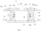
- a manufacturing mold 1 provided by the embodiment is configured to manufacture a multi-chamber tire; the manufacturing mold 1 comprises an upper holding plate 11 and a lower holding plate 13; the upper holding plate 11 and the lower holding plate 13 are arranged alternately and in parallel with each other, and there is an interval between the upper holding plate 11 and the lower holding plate 13.
- the upper holding plate 11 is located above the lower holding plate 13; alternatively, the upper holding plate 11 can also be located below the lower holding plate 13 according to the change of placement of the mold 1.
- the “above” and “below” herein do not confine the absolute location.
- a plurality of tire periphery forming sliders 16 and a plurality of central mold posts 18 are arranged in the intervals between the upper holding plate 11 and the lower holding plate 13; the plurality of tire periphery forming sliders 16 are arranged along a vertical direction of the intervals, and the sidewalls of the plurality of tire periphery forming sliders 16 are arranged to be abutted in order. Therefore, the plurality of periphery forming sliders 16 are arranged in a circular fashion and form a first annular post.
- the plurality of central mold posts 18 are arranged along the vertical direction of the intervals, and the plurality of central mold posts 18 are located at the inner side of the plurality of tire periphery forming sliders 16, sidewalls thereof being abutted other in order, therefore, the plurality of periphery forming sliders 16 are arranged in a circular fashion and form a second annular post. Therefore, an annular post is formed between the plurality of tire periphery forming sliders 18 and the plurality of central mold posts 18, and an annular chamber is formed between the tire periphery form sliders 16 and the central mold posts 18. Certainly, the upper end and lower end of the annular chamber are respectively provided with openings.
- the above mentioned central mold post 18 is provided with forming parts 19 which are arranged around the central mold post 18.
- a plurality of upper mold blocks 121 and a plurality of lower mold blocks 122 are arranged in the above mentioned annular chamber.
- the plurality of upper mold blocks 121 are connected with the lower end of the upper holding plate 11, that is, located at the opening of the upper end of the annular chamber; the plurality of upper mold blocks 121 are connected in order and arranged around the upper end of the annular chamber, thereby enclosing the opening of the upper end of the annular chamber.
- the plurality of lower mold blocks 122 are connected with the upper end of the lower holding plate 13, that is, located at the opening of the lower end of the annular chamber; the plurality of lower mold blocks 122 are connected in order and arranged around the lower end of the annular chamber, thereby enclosing the opening of the annular chamber.
- the plurality of upper mold blocks 121, the plurality of lower mold blocks 122, the plurality of tire periphery forming sliders 16 and the plurality of central mold posts 18 form an enclosed shaped chamber 10 which is annular shaped.
- the plurality of central mold posts 18 herein can also be formed integrally to form an annular shaped central mold post 18.
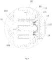
- the aforesaid chamber 10 is provided therein with a plurality of tire inner chamber forming sliders 17, the plurality of tire inner chamber forming sliders 17 are connected in order and arranged around the circumference of the chamber 10;
- the tire inner chamber forming sliders 17 include a circumferential ring, the circumferential ring is arranged around the chamber 10, the external side of the circumferential ring is abutted against the tire periphery forming sliders 16, and the inner side of the circumferential ring is provided with a plurality of spacedly arranged bosses; there are gaps between the adjacent bosses.
- a flexible portion chamber 101 is formed among the bosses of the tire inner chamber forming sliders 17, the upper mold blocks 121, the lower mold blocks 122 and the forming parts 19, and the flexible portion chamber 101 is configured to be filled with a forming flexible portion 21.
- An partitioned chamber 171 which is communicated with the upper mold blocks 121, the lower mold blocks 122 and the forming parts 19 is arranged between adjacent tire inner chamber forming sliders 17; the partitioned chamber 171 is configured to be filled with a forming isolated plate 23, the forming isolated plate 23 makes a plurality of isolating chambers 25 that are isolated from each other be formed in the flexible portion 21, and the isolating chambers 25 have outwards openings.
- An opening closure plate 107 is arranged outside the openings of above mentioned isolating chambers 25; the opening closure plate 107 encloses the openings of the isolating chambers 25 and is abutted against the isolated plate 23. Therefore, the plurality of opening closure plates 107 of the plurality of isolating chambers 25 are arranged annularly and an outer layer chamber 102 is formed between the plurality of opening closure plates 107 and the tire periphery forming sliders 16; the outer layer chamber 102 is arranged annularly.
- an external filling equipment is utilized to fill the outer layer chamber 102, hence an annular shaped out layer portion 22 is formed in the outer layer chamber 102, and the out layer portion 22 is abutted against the external side of the flexible portion 21 and isolates the openings of the isolating chambers 25 respectively.
- the above mentioned manufacturing mold 1 fills twice when it is used to manufacture the multi-chamber tire.
- the flexible portion chamber 101 and the partitioned chamber 171 are filled at the first time to form the flexible portion 21 and the isolated plate 23, and the flexible portion 21 is then left in the mold 1.
- the tire periphery forming sliders 16 is detached, the tire inner chamber forming sliders 17 is removed from the mold 1, the opening closure plate 107 is abutted against the opening of the enclosed isolating chamber 25 and further against the isolated plate 23, and the tire periphery forming sliders 16 is mounted; at this moment, an outer layer chamber 102 is form between the tire periphery forming sliders 16 and a plurality of opening closure plates 107, thereby performing the second filling and forming an out layer portion 22.
- the flexible portion 21 of the formed tire includes a plurality of isolating chambers 25 isolated with each other and arranged annularly.
- the adjacent isolating chambers 25 are isolated by the isolated plates 23. Therefore, when the out layer portion 22 is punctured by an external object and one isolating chamber 25 is pierced, only a certain single isolating chamber 25 is leaked; in this way, other un-punctured isolating chambers 25 are still in the gas-filled state, and the tire can still function and run in a high speed, thereby withstanding relatively big dynamic load along the radial direction; when the external object punctures the out layer portion 22 as well as adjacent isolating chambers 25, the isolated plate 23 between the two adjacent isolating chambers 25 withstands relatively big dynamic load, however, the tire can still function, and is adapt for running in a high speed; only in the case that adjacent isolating chambers are punctured by external bodies many times, the tire may be unsuitable to
- the multi-chamber tire manufactured by the manufacturing mold 1 provided by the embodiment can withstand multiple puncturing and still meet the high-speed run requirement, thereby extremely improving the service life and performance of the tire.
- the bosses mentioned above has rough and uneven surfaces, therefore, the formed flexible portion 21 is also rough and uneven.
- the shapes of outer surfaces of the bosses can be configured according to the requirement of forming the flexible portion 21.
- the bosses above are cone-shaped, however, the bosses can be in other shapes, and the particular shapes can be determined according to actual requirements.
- the circumferential ring mentioned above is provided with a cone cylinder 172, the cone cylinder 172 extends along a radial direction and is abutted against the forming part 19, therefore, the isolated plate 23 forms ventilation holes after filling.
- the plurality of tire periphery forming sliders 16 can be composed of a plurality of parts; surely, the plurality of tire periphery forming sliders 16 can also be formed integrally, that is, formed into one part.
- the specific configuration can be set as actual requirements.
- the central mold post 18 is provided in its middle portion with a bulge loop bulging outwards; the upper mold blocks 121 and the lower mold blocks 122 are arranged alternately with each other and abutted against the upper end and the lower end of the bulge loop respectively, and the above mentioned forming part 19 is arranged on the bulge loop, thereby facilitating the securing and assembly of the upper mold blocks 121 and the lower mold blocks 122.
- the above mentioned forming part 19 is provided with a filling plug 116, one end of the filling plug 116 is connected to the tire inner chamber forming sliders 17 and another end of which is abutted against the bulge loop. After the flexible portion 21 is formed, the filling plug 116 penetrates the flexible portion 21 and communicates the isolating chamber 25 with the outside, so that the isolating chamber 25 can be filled with gas with an external filling equipment.
- one or more above mentioned filling plug(s) 116 is/are respectively arranged at each isolating chamber 25.
- the filling plug 116 is sheathed with a metal loop 115, and then the metal loop 115 will be arranged in the flexible portion 21 after the flexible portion 21 is formed, which is convenient for the flexible portion 21 to dissipate heat.
- the tire inner chamber forming sliders 17 are shaped to be symmetrical, and the formed flexible portion 21 is also symmetrical.
- the gaps between the above mentioned bosses include a circumferential slot 104, an inner side of the circumferential slot 104 is communicated with a flexible portion chamber 101; two ends of the flexible portion chamber 101 are communicated with the partitioned chamber 171. Then, after the first filling, the circumferential slot 104 forms a circumferential plate 23.
- the sidewalls of the circumferential plate 23 are respectively abutted against the flexible portion 21, the isolated plate 23 and the out layer portion 22, thereby isolating the isolating chambers 25 into side chambers which are isolated from each other and the two side chambers of the isolating chambers 25 are arranged along an axial direction.
- each isolating chamber 25 needs to be provided with two filling plugs 116 respectively and the two filling plugs 116 are respectively arranged at two ends of the circumferential slot 104. Then, only after the circumferential plate 23 is formed can the two filling plugs 116 be communicated with the two side chambers respectively.
- the inner side of the above mentioned circumferential slot 104 is communicated with the flexible portion chamber 101, that is, the inner side of the circumferential slot 104 is provided with an opening; during the second filling process, the opening is helpful to remove the tire inner chamber forming sliders 17 out from the mold 1.
- the gaps between the bosses further include auxiliary circumferential slots 103, inner sides of the auxiliary circumferential slots 103 are communicated with a flexible portion chamber 101; two ends of each auxiliary circumferential slot 103 are connected with the partitioned chamber 171. Then, after the first filling, the auxiliary circumferential slots 103 form an auxiliary circumferential plate 24.
- the sidewalls of the auxiliary circumferential plate 24 are respectively abutted against the flexible portion 21, the isolating plate 23 and the out layer portion 22, so that the isolating chamber 25 is isolated into chamber units 106 which are isolated from each other, and the two chamber units 106 of the side chamber are arranged along an axial direction.
- the filling plugs 116 of above mentioned corresponding side chambers are arranged at one end of the auxiliary circumferential slot 103, and include a pipeline 117 which extends to the other end.
- the filling plug 116 of each side chamber can be connected with two chamber units 106, therefore, the two chamber units 106 of each side chamber can be filled with gas by only one filling plug 116, thereby avoiding over numbered filling plugs 116 and facilitating the manufacturing of the multi-chamber tire.
- the external sides of the upper holding plate 11 and the lower holding plate 13 respectively extend beyond the tire periphery forming sliders 16, and the tire periphery forming sliders 16 is provided with a holding block 14; the holding block 14 is arranged to extend along an axial direction and be connected with the tire periphery forming sliders 16 by a locking structure 15.
- the tire periphery forming sliders 16 can be moved by directly operating the locking structure 15, so that the tire periphery forming sliders 16 can be abutted against the external sides of the upper mold blocks 121 and the lower mold blocks 122, thereby making the assembly of the whole mold 1 be more stable.
- the above mentioned locking structure 15 includes a screw 151 which penetrates the holding block 14; the screw 151 passes through the holding block 14 and is correspondingly connected to the tire periphery forming sliders 16.
- the tire periphery forming sliders 16 can be moved along the radial direction by turning the screw 151, so that the tire periphery forming sliders 16 can move towards or against the upper mold blocks 121 and the lower mold blocks 122.
- the external side of the screw 151 is provided with a puller 152.
- the screw 151 can be disconnected from connecting hooks of the tire periphery forming sliders 16 by turning the screw 151.
- the puller 152 By directly pulling the puller 152 outwards, the screw 151 can drive the tire periphery forming sliders 16 to move outwards.
- a screw bolt 113 runs through between the upper holding plate 11 and the lower holding plate 13, and the screw bolt 113 is arranged along an axial direction.
- the screw bolt 113 passes through the upper holding plate 11 and the lower holding plate 13 respectively; therefore, the gap between the upper holding plate 11 and the lower holding plate 13 can be adjusted through turning the screw bolt 113.
- the mold removal operation can be manual; if the tires are mass produced, the mold removal operation can be automatic, and the details thereof are as follows.
- a plurality of first magnetic conducting blocks 111 are located on the upper holding plate 11, the plurality of first magnetic conducting blocks 111 are arranged annularly and aligned with the upper mold blocks 121 respectively; surely, they can also be not aligned with the upper mold blocks 121; the upper holding plate 11 is made of non-magnetic conducting material such as aluminum.
- the first magnetic conducting block 111 will not produce magnetic force inside the mold 1, and can reduce the weight of the holding plate 11; in this way, it is convenient for an external mechanical arm to lift the upper holding plate 11 with less force, thereby realizing automatic disassembly of the upper mold blocks 121.
- a second magnetic conducting block 112 is arranged on the upper holding plate 11, and the second magnetic conducting block 112 is located at the inner side of the plurality of central mold posts 18.
- a power block is arranged outside the above mentioned tire periphery forming sliders 106; by the connection of the power block with an external air cylinder or others, the disassembly of the tire periphery forming sliders can be realized.
- the manufacturing mold 1 secured by the above mentioned locking structure is mainly suitable for manual tire production in small quantity.
- an upper impacting structure can be utilized to replace the locking structure and be connected with the gas cylinder circumferentially; furthermore, an electromagnetism connection platform is arranged in the tire inner chamber forming sliders 17.
Landscapes
- Engineering & Computer Science (AREA)
- Mechanical Engineering (AREA)
- Moulds For Moulding Plastics Or The Like (AREA)
- Tyre Moulding (AREA)
Claims (11)
- Mehrkammerreifen-Fertigungsgießform (1), die eine obere Halteplatte (11) und eine untere Halteplatte (12) umfasst; wobei die obere Halteplatte (11) und die untere Halteplatte (12) abwechselnd und zueinander parallel und mit Zwischenräumen zwischen der oberen Halteplatte (11) und der unteren Halteplatte (12) angeordnet sind;
wobei in den Zwischenräumen mehrere Reifenumfangs-Formungsgleiter (16), obere Gießformblöcke (121), untere Gießformblöcke (122) und mittlere Gießformsäulen (18) angeordnet sind; die Reifenumfangs-Formungsgleiter (16) in der Höhenrichtung der Zwischenräume angeordnet sind und die mehreren Reifenumfangs-Formungsgleiter (16) der Reihe nach verbunden und ringförmig angeordnet sind; die mittleren Gießformsäulen (18) in der Höhenrichtung der Zwischenräume ringförmig angeordnet sind und sich an einer Innenseite der mehreren Reifenumfangs-Formungsgleiter (16) befinden und abwechselnd mit den mehreren Reifenumfangs-Formungsgleitern (16) angeordnet sind; und die mittleren Gießformsäulen (18) innen mit einem Formungsabschnitt (19) konfiguriert sind, der um die mittlere Gießformsäule (18) angeordnet ist;
wobei ein unteres Ende der oberen Halteplatte (11) mit mehreren oberen Gießformblöcken (121) verbunden ist, die in einem Kreis angeordnet sind; und aus mehreren der oberen Gießformblöcke (121), mehreren der unteren Gießformblöcken (122), den Formungsabschnitten (19) und mehreren der Reifenumfangs-Formungsgleiter (16) eine geschlossene Kammer gebildet ist;
wobei in der Kammer mehrere Reifeninnenkammer-Formungsgleiter (17) vorgesehen sind, die der Reihe nach verbunden und um die Kammer angeordnet sind; der Reifeninnenkammer-Formungsgleiter (17) einen Umfangsring aufweist, der um einen Umfang angeordnet ist; eine Außenseite des Umfangsrings an den Reifenumfangs-Formungsgleitern (16) anliegt, eine Innenseite des Umfangsrings mit mehreren beabstandet angeordneten Erhebungen versehen ist und zwischen benachbarten Erhebungen Spalte vorhanden sind; eine Kammer für flexiblen Abschnitt, die konfiguriert ist, mit dem flexiblen Formungsabschnitt (21) gefüllt zu werden, zwischen den Erhebungen der Reifeninnenkammer-Formungsgleiter (17) und dem Formungsabschnitt (19), den oberen Gießformblöcken (121) und den unteren Gießformblöcken (122) gebildet ist; eine unterteilte Kammer (171), die mit den oberen Gießformblöcken (121), den unteren Gießformblöcken (122) und den Formungsabschnitten (19) kommuniziert und konfiguriert ist, mit einer isolierten Formungsplatte (23) gefüllt zu werden, um so mehrere isolierte Kammern (25) zu formen, die in dem flexiblen Abschnitt voneinander isoliert sind, zwischen benachbarten Reifeninnenkammer-Formungsgleitern (17) angeordnet ist; und die isolierte Kammer (25) eine Öffnung nach außen besitzt;
wobei an der Öffnung der isolierten Kammer (25) eine Öffnungsverschlussplatte (107) vorgesehen ist, die die Öffnung der isolierten Kammer verschließt und die konfiguriert ist, an der isolierten Platte (23) anzuliegen, nachdem die unterteilte Kammer (171) mit dem flexiblen Formungsabschnitt (21) gefüllt worden ist und die Reifeninnenkammer-Formungsgleiter (17) entfernt worden sind; eine Außenschichtkammer, die konfiguriert ist, mit dem Außenschicht-Formungsabschnitt gefüllt zu werden, zwischen den Öffnungsverschlussplatten (107) und den Reifenumfangs-Formungsgleitern (16) ausgebildet ist; und die Außenschichtkammer in einem Kreis angeordnet ist. - Mehrkammerreifen-Fertigungsgießform (1) nach Anspruch 1, dadurch gekennzeichnet, dass die Oberflächen der Erhebungen rau und uneben sind.
- Mehrkammerreifen-Fertigungsgießform (1) nach Anspruch 1, dadurch gekennzeichnet, dass die mehreren Reifenumfangs-Formungsgleiter (16) oder die mehreren Reifeninnenkammer-Formungsgleiter (17) einteilig ausgebildet sind.
- Mehrkammerreifen-Fertigungsgießform (1) nach Anspruch 1, dadurch gekennzeichnet, dass ein Umfangsring der Reifeninnenkammer-Formungsgleiter (17) mit mehreren Kegelzylindern (172) versehen ist, die in radialen Richtungen angeordnet sind, wobei die Kegelzylinder (172) an dem Formungsabschnitt (19) anliegen.
- Mehrkammerreifen-Fertigungsgießform (1) nach einem der Ansprüche 1-4, dadurch gekennzeichnet, dass eine Innenseite eines mittleren Abschnitts der mittleren Gießformsäule (18) mit einer Ausbauchungsschleife versehen ist; die oberen Gießformblöcke (121) und die unteren Gießformblöcke (122) an den oberen Enden bzw. den unteren Enden der Ausbauchungsschleife bzw. an einem Innenseiten-Formungselement anliegen; und das Formungselement (19) an der Ausbauchungsschleife anliegt und daran mit mehreren Füllstopfen versehen ist, wobei die Füllstopfen mit Metallschleifen umhüllt sind und wobei die Füllstopfen an den Reifeninnenkammer-Formungsgleitern (17) anliegen.
- Mehrkammerreifen-Fertigungsgießform (1) nach einem der Ansprüche 1-4, dadurch gekennzeichnet, dass Spalte zwischen den Erhebungen einen Umfangsschlitz (104) aufweisen, der mit der Kammer (101) für flexiblen Abschnitt bzw. mit der unterteilten Kammer (171) kommuniziert und konfiguriert ist, mit einer Umfangsformungsplatte gefüllt zu werden.
- Mehrkammerreifen-Fertigungsgießform (1) nach einem der Ansprüche 1 bis 4 dadurch gekennzeichnet, dass Spalte zwischen den Erhebungen ferner einen Hilfs-Umfangsschlitz (103) aufweisen, der mit der Kammer (101) für flexiblen Abschnitt bzw. mit der unterteilten Kammer (171) kommuniziert und konfiguriert ist, mit einer Hilfs-Umfangsformungsplatte gefüllt zu werden.
- Mehrkammerreifen-Fertigungsgießform (1) nach einem der Ansprüche 1 bis 4, dadurch gekennzeichnet, dass sich die obere Halteplatte (11) und die untere Halteplatte (12) über die Reifenumfangs-Formungsgleiter (16) hinaus erstrecken und mit jeweiligen Halteblöcken (14) versehen sind, wobei jeder Halteblock (14) mit einer Verriegelungsstruktur (15) versehen ist, die mit den Reifenumfangs-Formungsgleitern (16) verbunden ist und konfiguriert ist, eine Bewegung der Reifenumfangs-Formungsgleiter (16) zu ermöglichen.
- Mehrkammerreifen-Fertigungsgießform (1) nach Anspruch 8, dadurch gekennzeichnet, dass die Verriegelungsstruktur (15) eine Schraube (151) aufweist, die durch den Halteblock (14) bzw. einen Außenkammergleiter verläuft.
- Mehrkammerreifen-Fertigungsgießform (1) nach einem der Ansprüche 1-4, dadurch gekennzeichnet, dass ein Schraubbolzen (113) zwischen der oberen Halteplatte (11) und der unteren Halteplatte (12) verläuft; wobei der Schraubbolzen (113) in axialer Richtung angeordnet ist.
- Mehrkammerreifen-Fertigungsgießform (1) nach einem der Ansprüche 1 bis 4, dadurch gekennzeichnet, dass an der oberen Halteplatte (11) mehrere erste magnetische leitende Blöcke (111) vorgesehen sind und die mehreren ersten magnetischen leitenden Blöcke (111) in einem Kreis angeordnet sind.
Applications Claiming Priority (1)
| Application Number | Priority Date | Filing Date | Title |
|---|---|---|---|
| PCT/CN2013/084139 WO2015042788A1 (zh) | 2013-09-25 | 2013-09-25 | 多型腔轮胎的制造模具 |
Publications (3)
| Publication Number | Publication Date |
|---|---|
| EP3050690A1 EP3050690A1 (de) | 2016-08-03 |
| EP3050690A4 EP3050690A4 (de) | 2017-05-24 |
| EP3050690B1 true EP3050690B1 (de) | 2019-12-25 |
Family
ID=52741744
Family Applications (1)
| Application Number | Title | Priority Date | Filing Date |
|---|---|---|---|
| EP13894096.0A Active EP3050690B1 (de) | 2013-09-25 | 2013-09-25 | Mehrkammerreifenherstellungsform |
Country Status (7)
| Country | Link |
|---|---|
| US (1) | US9527253B2 (de) |
| EP (1) | EP3050690B1 (de) |
| JP (1) | JP6093913B2 (de) |
| KR (1) | KR102040360B1 (de) |
| CN (1) | CN105531091B (de) |
| ES (1) | ES2779059T3 (de) |
| WO (1) | WO2015042788A1 (de) |
Cited By (1)
| Publication number | Priority date | Publication date | Assignee | Title |
|---|---|---|---|---|
| US11845347B2 (en) | 2021-05-12 | 2023-12-19 | David Alan Copeland | Precision charging control of an untethered vehicle with a modular vehicle charging roadway |
Families Citing this family (2)
| Publication number | Priority date | Publication date | Assignee | Title |
|---|---|---|---|---|
| CN105773878B (zh) * | 2016-05-13 | 2017-12-01 | 中策橡胶集团有限公司 | 一种轮胎成型胶囊囊体的成型模具 |
| CN106003778B (zh) * | 2016-05-13 | 2019-01-18 | 中策橡胶集团有限公司 | 一种轮胎成型胶囊的囊体制备装置和制备方法 |
Family Cites Families (15)
| Publication number | Priority date | Publication date | Assignee | Title |
|---|---|---|---|---|
| GB212437A (en) * | 1923-04-04 | 1924-03-13 | O & W Company | Improvements in or relating to vehicle tires |
| GB399356A (en) * | 1932-01-12 | 1933-10-05 | Maurice Baudou | Improvements in cellular cushion tyres and in moulds for the production of such tyres |
| JPS4616403Y1 (de) * | 1966-12-03 | 1971-06-08 | ||
| JPS4718201U (de) * | 1971-04-01 | 1972-10-31 | ||
| US3901300A (en) * | 1972-03-24 | 1975-08-26 | Raleigh Industries Ltd | Non-inflatable tire and apparatus for producing same |
| US4267873A (en) * | 1979-06-15 | 1981-05-19 | B. J. Mccoll & Company, Ltd. | Composite high mobility tire for off-road vehicles |
| CN1064648A (zh) * | 1991-12-18 | 1992-09-23 | 冼韬 | 多室式轮胎 |
| US5449483A (en) * | 1994-02-04 | 1995-09-12 | The Goodyear Tire & Rubber Company | Method and apparatus for making a tire mold |
| US5641365A (en) * | 1994-12-12 | 1997-06-24 | The Hyper Corporation | Pre-pressurized in-line skate wheel |
| CN2286685Y (zh) * | 1996-12-27 | 1998-07-29 | 凌锦荣 | 连锁开闭多室式内胎 |
| JP4608351B2 (ja) * | 2005-04-04 | 2011-01-12 | 株式会社ブリヂストン | 空気入りタイヤの製造方法 |
| JP4735124B2 (ja) * | 2005-08-17 | 2011-07-27 | 横浜ゴム株式会社 | 空気入りタイヤの製造方法 |
| CN101219567B (zh) * | 2007-01-09 | 2011-03-16 | 昊华南方(桂林)橡胶有限责任公司 | 巨型轮胎活络模具 |
| JP2010131864A (ja) * | 2008-12-04 | 2010-06-17 | Bridgestone Corp | ブラダー |
| CN201760991U (zh) * | 2010-09-08 | 2011-03-16 | 四川远星橡胶有限责任公司 | 一种轮胎硫化模具及其加工制造的轮胎 |
-
2013
- 2013-09-25 ES ES13894096T patent/ES2779059T3/es active Active
- 2013-09-25 EP EP13894096.0A patent/EP3050690B1/de active Active
- 2013-09-25 US US15/024,477 patent/US9527253B2/en not_active Expired - Fee Related
- 2013-09-25 JP JP2016516899A patent/JP6093913B2/ja not_active Expired - Fee Related
- 2013-09-25 WO PCT/CN2013/084139 patent/WO2015042788A1/zh not_active Ceased
- 2013-09-25 CN CN201380079495.5A patent/CN105531091B/zh not_active Expired - Fee Related
- 2013-09-25 KR KR1020167010266A patent/KR102040360B1/ko not_active Expired - Fee Related
Non-Patent Citations (1)
| Title |
|---|
| None * |
Cited By (1)
| Publication number | Priority date | Publication date | Assignee | Title |
|---|---|---|---|---|
| US11845347B2 (en) | 2021-05-12 | 2023-12-19 | David Alan Copeland | Precision charging control of an untethered vehicle with a modular vehicle charging roadway |
Also Published As
| Publication number | Publication date |
|---|---|
| EP3050690A4 (de) | 2017-05-24 |
| JP2016532571A (ja) | 2016-10-20 |
| US20160236429A1 (en) | 2016-08-18 |
| WO2015042788A1 (zh) | 2015-04-02 |
| KR102040360B1 (ko) | 2019-11-04 |
| EP3050690A1 (de) | 2016-08-03 |
| CN105531091A (zh) | 2016-04-27 |
| US9527253B2 (en) | 2016-12-27 |
| KR20160062058A (ko) | 2016-06-01 |
| CN105531091B (zh) | 2017-05-03 |
| JP6093913B2 (ja) | 2017-03-08 |
| ES2779059T3 (es) | 2020-08-13 |
Similar Documents
| Publication | Publication Date | Title |
|---|---|---|
| JP2012533467A (ja) | 車輌防爆安全タイヤ | |
| US11491751B2 (en) | Tire mold and pneumatic tire | |
| US9527253B2 (en) | Multi-chamber tire manufacturing mold | |
| US10870248B2 (en) | Non-symmetrical tread ring parting line mold | |
| US9561631B2 (en) | Mold for tire having an annular insert with a concentric groove | |
| WO2016106190A1 (en) | Tire mold and vent insert having corresponding surfaces | |
| CN106061756B (zh) | 多型腔轮胎 | |
| CN205553769U (zh) | 开放式车轮 | |
| CN100396462C (zh) | 轮胎模具 | |
| CN210970553U (zh) | 一种防爆轮胎及其制备模具 | |
| CN202344724U (zh) | 轮胎硫化夹持盘 | |
| CN110722930A (zh) | 一种防爆轮胎及其制备模具和制备方法 | |
| CN213496039U (zh) | 一种便于脱模的汽车金属零部件模具 | |
| JP6122686B2 (ja) | 農業機械用のタイヤの製造方法 | |
| CN103921625A (zh) | 多仓轮胎及其制作方法 | |
| CN110815886A (zh) | 一种两半式轮胎模具 | |
| CN101643005B (zh) | 一种橡胶圈多空腔内胎 | |
| CN107901461B (zh) | 硫化轮胎冷却机及冷却方法 | |
| CN202242807U (zh) | 一种组合式内胎 | |
| TWM587112U (zh) | 免充氣輪子灌注成形裝置 | |
| JP2016034744A (ja) | タイヤ加硫用ブラダの製造方法およびタイヤ加硫用ブラダ | |
| JP2014019136A (ja) | タイヤ加硫用ブラダおよび空気入りタイヤの製造方法 |
Legal Events
| Date | Code | Title | Description |
|---|---|---|---|
| PUAI | Public reference made under article 153(3) epc to a published international application that has entered the european phase |
Free format text: ORIGINAL CODE: 0009012 |
|
| 17P | Request for examination filed |
Effective date: 20160425 |
|
| AK | Designated contracting states |
Kind code of ref document: A1 Designated state(s): AL AT BE BG CH CY CZ DE DK EE ES FI FR GB GR HR HU IE IS IT LI LT LU LV MC MK MT NL NO PL PT RO RS SE SI SK SM TR |
|
| AX | Request for extension of the european patent |
Extension state: BA ME |
|
| DAX | Request for extension of the european patent (deleted) | ||
| A4 | Supplementary search report drawn up and despatched |
Effective date: 20170425 |
|
| RIC1 | Information provided on ipc code assigned before grant |
Ipc: B29D 30/02 20060101ALI20170419BHEP Ipc: B29C 33/30 20060101AFI20170419BHEP |
|
| STAA | Information on the status of an ep patent application or granted ep patent |
Free format text: STATUS: EXAMINATION IS IN PROGRESS |
|
| 17Q | First examination report despatched |
Effective date: 20181025 |
|
| REG | Reference to a national code |
Ref country code: DE Ref legal event code: R079 Ref document number: 602013064488 Country of ref document: DE Free format text: PREVIOUS MAIN CLASS: B29C0033300000 Ipc: B29D0030020000 |
|
| GRAP | Despatch of communication of intention to grant a patent |
Free format text: ORIGINAL CODE: EPIDOSNIGR1 |
|
| STAA | Information on the status of an ep patent application or granted ep patent |
Free format text: STATUS: GRANT OF PATENT IS INTENDED |
|
| RIC1 | Information provided on ipc code assigned before grant |
Ipc: B60C 5/24 20060101ALI20190716BHEP Ipc: B29D 30/06 20060101ALI20190716BHEP Ipc: B29D 30/02 20060101AFI20190716BHEP Ipc: B29C 33/48 20060101ALI20190716BHEP |
|
| INTG | Intention to grant announced |
Effective date: 20190807 |
|
| GRAS | Grant fee paid |
Free format text: ORIGINAL CODE: EPIDOSNIGR3 |
|
| GRAA | (expected) grant |
Free format text: ORIGINAL CODE: 0009210 |
|
| STAA | Information on the status of an ep patent application or granted ep patent |
Free format text: STATUS: THE PATENT HAS BEEN GRANTED |
|
| AK | Designated contracting states |
Kind code of ref document: B1 Designated state(s): AL AT BE BG CH CY CZ DE DK EE ES FI FR GB GR HR HU IE IS IT LI LT LU LV MC MK MT NL NO PL PT RO RS SE SI SK SM TR |
|
| REG | Reference to a national code |
Ref country code: GB Ref legal event code: FG4D |
|
| REG | Reference to a national code |
Ref country code: CH Ref legal event code: EP |
|
| REG | Reference to a national code |
Ref country code: AT Ref legal event code: REF Ref document number: 1216697 Country of ref document: AT Kind code of ref document: T Effective date: 20200115 |
|
| REG | Reference to a national code |
Ref country code: DE Ref legal event code: R096 Ref document number: 602013064488 Country of ref document: DE |
|
| REG | Reference to a national code |
Ref country code: IE Ref legal event code: FG4D |
|
| REG | Reference to a national code |
Ref country code: NL Ref legal event code: FP |
|
| REG | Reference to a national code |
Ref country code: FI Ref legal event code: FGE |
|
| PG25 | Lapsed in a contracting state [announced via postgrant information from national office to epo] |
Ref country code: NO Free format text: LAPSE BECAUSE OF FAILURE TO SUBMIT A TRANSLATION OF THE DESCRIPTION OR TO PAY THE FEE WITHIN THE PRESCRIBED TIME-LIMIT Effective date: 20200325 Ref country code: GR Free format text: LAPSE BECAUSE OF FAILURE TO SUBMIT A TRANSLATION OF THE DESCRIPTION OR TO PAY THE FEE WITHIN THE PRESCRIBED TIME-LIMIT Effective date: 20200326 Ref country code: LT Free format text: LAPSE BECAUSE OF FAILURE TO SUBMIT A TRANSLATION OF THE DESCRIPTION OR TO PAY THE FEE WITHIN THE PRESCRIBED TIME-LIMIT Effective date: 20191225 Ref country code: LV Free format text: LAPSE BECAUSE OF FAILURE TO SUBMIT A TRANSLATION OF THE DESCRIPTION OR TO PAY THE FEE WITHIN THE PRESCRIBED TIME-LIMIT Effective date: 20191225 Ref country code: SE Free format text: LAPSE BECAUSE OF FAILURE TO SUBMIT A TRANSLATION OF THE DESCRIPTION OR TO PAY THE FEE WITHIN THE PRESCRIBED TIME-LIMIT Effective date: 20191225 Ref country code: BG Free format text: LAPSE BECAUSE OF FAILURE TO SUBMIT A TRANSLATION OF THE DESCRIPTION OR TO PAY THE FEE WITHIN THE PRESCRIBED TIME-LIMIT Effective date: 20200325 |
|
| REG | Reference to a national code |
Ref country code: LT Ref legal event code: MG4D |
|
| PG25 | Lapsed in a contracting state [announced via postgrant information from national office to epo] |
Ref country code: RS Free format text: LAPSE BECAUSE OF FAILURE TO SUBMIT A TRANSLATION OF THE DESCRIPTION OR TO PAY THE FEE WITHIN THE PRESCRIBED TIME-LIMIT Effective date: 20191225 Ref country code: HR Free format text: LAPSE BECAUSE OF FAILURE TO SUBMIT A TRANSLATION OF THE DESCRIPTION OR TO PAY THE FEE WITHIN THE PRESCRIBED TIME-LIMIT Effective date: 20191225 |
|
| PG25 | Lapsed in a contracting state [announced via postgrant information from national office to epo] |
Ref country code: AL Free format text: LAPSE BECAUSE OF FAILURE TO SUBMIT A TRANSLATION OF THE DESCRIPTION OR TO PAY THE FEE WITHIN THE PRESCRIBED TIME-LIMIT Effective date: 20191225 |
|
| PG25 | Lapsed in a contracting state [announced via postgrant information from national office to epo] |
Ref country code: EE Free format text: LAPSE BECAUSE OF FAILURE TO SUBMIT A TRANSLATION OF THE DESCRIPTION OR TO PAY THE FEE WITHIN THE PRESCRIBED TIME-LIMIT Effective date: 20191225 Ref country code: PT Free format text: LAPSE BECAUSE OF FAILURE TO SUBMIT A TRANSLATION OF THE DESCRIPTION OR TO PAY THE FEE WITHIN THE PRESCRIBED TIME-LIMIT Effective date: 20200520 Ref country code: CZ Free format text: LAPSE BECAUSE OF FAILURE TO SUBMIT A TRANSLATION OF THE DESCRIPTION OR TO PAY THE FEE WITHIN THE PRESCRIBED TIME-LIMIT Effective date: 20191225 Ref country code: RO Free format text: LAPSE BECAUSE OF FAILURE TO SUBMIT A TRANSLATION OF THE DESCRIPTION OR TO PAY THE FEE WITHIN THE PRESCRIBED TIME-LIMIT Effective date: 20191225 |
|
| REG | Reference to a national code |
Ref country code: ES Ref legal event code: FG2A Ref document number: 2779059 Country of ref document: ES Kind code of ref document: T3 Effective date: 20200813 |
|
| PG25 | Lapsed in a contracting state [announced via postgrant information from national office to epo] |
Ref country code: SK Free format text: LAPSE BECAUSE OF FAILURE TO SUBMIT A TRANSLATION OF THE DESCRIPTION OR TO PAY THE FEE WITHIN THE PRESCRIBED TIME-LIMIT Effective date: 20191225 Ref country code: SM Free format text: LAPSE BECAUSE OF FAILURE TO SUBMIT A TRANSLATION OF THE DESCRIPTION OR TO PAY THE FEE WITHIN THE PRESCRIBED TIME-LIMIT Effective date: 20191225 |
|
| REG | Reference to a national code |
Ref country code: DE Ref legal event code: R097 Ref document number: 602013064488 Country of ref document: DE |
|
| PG25 | Lapsed in a contracting state [announced via postgrant information from national office to epo] |
Ref country code: DK Free format text: LAPSE BECAUSE OF FAILURE TO SUBMIT A TRANSLATION OF THE DESCRIPTION OR TO PAY THE FEE WITHIN THE PRESCRIBED TIME-LIMIT Effective date: 20191225 |
|
| PLBE | No opposition filed within time limit |
Free format text: ORIGINAL CODE: 0009261 |
|
| STAA | Information on the status of an ep patent application or granted ep patent |
Free format text: STATUS: NO OPPOSITION FILED WITHIN TIME LIMIT |
|
| REG | Reference to a national code |
Ref country code: AT Ref legal event code: MK05 Ref document number: 1216697 Country of ref document: AT Kind code of ref document: T Effective date: 20191225 |
|
| PG25 | Lapsed in a contracting state [announced via postgrant information from national office to epo] |
Ref country code: SI Free format text: LAPSE BECAUSE OF FAILURE TO SUBMIT A TRANSLATION OF THE DESCRIPTION OR TO PAY THE FEE WITHIN THE PRESCRIBED TIME-LIMIT Effective date: 20191225 |
|
| 26N | No opposition filed |
Effective date: 20200928 |
|
| PG25 | Lapsed in a contracting state [announced via postgrant information from national office to epo] |
Ref country code: AT Free format text: LAPSE BECAUSE OF FAILURE TO SUBMIT A TRANSLATION OF THE DESCRIPTION OR TO PAY THE FEE WITHIN THE PRESCRIBED TIME-LIMIT Effective date: 20191225 |
|
| PG25 | Lapsed in a contracting state [announced via postgrant information from national office to epo] |
Ref country code: PL Free format text: LAPSE BECAUSE OF FAILURE TO SUBMIT A TRANSLATION OF THE DESCRIPTION OR TO PAY THE FEE WITHIN THE PRESCRIBED TIME-LIMIT Effective date: 20191225 |
|
| PG25 | Lapsed in a contracting state [announced via postgrant information from national office to epo] |
Ref country code: MC Free format text: LAPSE BECAUSE OF FAILURE TO SUBMIT A TRANSLATION OF THE DESCRIPTION OR TO PAY THE FEE WITHIN THE PRESCRIBED TIME-LIMIT Effective date: 20191225 |
|
| REG | Reference to a national code |
Ref country code: BE Ref legal event code: MM Effective date: 20200930 |
|
| PG25 | Lapsed in a contracting state [announced via postgrant information from national office to epo] |
Ref country code: LU Free format text: LAPSE BECAUSE OF NON-PAYMENT OF DUE FEES Effective date: 20200925 |
|
| PG25 | Lapsed in a contracting state [announced via postgrant information from national office to epo] |
Ref country code: IE Free format text: LAPSE BECAUSE OF NON-PAYMENT OF DUE FEES Effective date: 20200925 Ref country code: BE Free format text: LAPSE BECAUSE OF NON-PAYMENT OF DUE FEES Effective date: 20200930 |
|
| PGFP | Annual fee paid to national office [announced via postgrant information from national office to epo] |
Ref country code: FR Payment date: 20210922 Year of fee payment: 9 Ref country code: IT Payment date: 20210922 Year of fee payment: 9 Ref country code: FI Payment date: 20210921 Year of fee payment: 9 Ref country code: CH Payment date: 20210920 Year of fee payment: 9 Ref country code: NL Payment date: 20210920 Year of fee payment: 9 |
|
| PGFP | Annual fee paid to national office [announced via postgrant information from national office to epo] |
Ref country code: IS Payment date: 20210910 Year of fee payment: 9 Ref country code: DE Payment date: 20210920 Year of fee payment: 9 Ref country code: TR Payment date: 20210923 Year of fee payment: 9 Ref country code: GB Payment date: 20210920 Year of fee payment: 9 |
|
| PGFP | Annual fee paid to national office [announced via postgrant information from national office to epo] |
Ref country code: ES Payment date: 20211125 Year of fee payment: 9 |
|
| PG25 | Lapsed in a contracting state [announced via postgrant information from national office to epo] |
Ref country code: MT Free format text: LAPSE BECAUSE OF FAILURE TO SUBMIT A TRANSLATION OF THE DESCRIPTION OR TO PAY THE FEE WITHIN THE PRESCRIBED TIME-LIMIT Effective date: 20191225 Ref country code: CY Free format text: LAPSE BECAUSE OF FAILURE TO SUBMIT A TRANSLATION OF THE DESCRIPTION OR TO PAY THE FEE WITHIN THE PRESCRIBED TIME-LIMIT Effective date: 20191225 |
|
| PG25 | Lapsed in a contracting state [announced via postgrant information from national office to epo] |
Ref country code: MK Free format text: LAPSE BECAUSE OF FAILURE TO SUBMIT A TRANSLATION OF THE DESCRIPTION OR TO PAY THE FEE WITHIN THE PRESCRIBED TIME-LIMIT Effective date: 20191225 |
|
| REG | Reference to a national code |
Ref country code: DE Ref legal event code: R119 Ref document number: 602013064488 Country of ref document: DE |
|
| PG25 | Lapsed in a contracting state [announced via postgrant information from national office to epo] |
Ref country code: FI Free format text: LAPSE BECAUSE OF NON-PAYMENT OF DUE FEES Effective date: 20220925 |
|
| REG | Reference to a national code |
Ref country code: CH Ref legal event code: PL |
|
| REG | Reference to a national code |
Ref country code: NL Ref legal event code: MM Effective date: 20221001 |
|
| GBPC | Gb: european patent ceased through non-payment of renewal fee |
Effective date: 20220925 |
|
| PG25 | Lapsed in a contracting state [announced via postgrant information from national office to epo] |
Ref country code: NL Free format text: LAPSE BECAUSE OF NON-PAYMENT OF DUE FEES Effective date: 20221001 |
|
| PG25 | Lapsed in a contracting state [announced via postgrant information from national office to epo] |
Ref country code: LI Free format text: LAPSE BECAUSE OF NON-PAYMENT OF DUE FEES Effective date: 20220930 Ref country code: FR Free format text: LAPSE BECAUSE OF NON-PAYMENT OF DUE FEES Effective date: 20220930 Ref country code: DE Free format text: LAPSE BECAUSE OF NON-PAYMENT OF DUE FEES Effective date: 20230401 Ref country code: CH Free format text: LAPSE BECAUSE OF NON-PAYMENT OF DUE FEES Effective date: 20220930 |
|
| PG25 | Lapsed in a contracting state [announced via postgrant information from national office to epo] |
Ref country code: IT Free format text: LAPSE BECAUSE OF NON-PAYMENT OF DUE FEES Effective date: 20220925 Ref country code: GB Free format text: LAPSE BECAUSE OF NON-PAYMENT OF DUE FEES Effective date: 20220925 |
|
| REG | Reference to a national code |
Ref country code: ES Ref legal event code: FD2A Effective date: 20231102 |
|
| PG25 | Lapsed in a contracting state [announced via postgrant information from national office to epo] |
Ref country code: ES Free format text: LAPSE BECAUSE OF NON-PAYMENT OF DUE FEES Effective date: 20220926 |
|
| PG25 | Lapsed in a contracting state [announced via postgrant information from national office to epo] |
Ref country code: ES Free format text: LAPSE BECAUSE OF NON-PAYMENT OF DUE FEES Effective date: 20220926 |
|
| PG25 | Lapsed in a contracting state [announced via postgrant information from national office to epo] |
Ref country code: TR Free format text: LAPSE BECAUSE OF NON-PAYMENT OF DUE FEES Effective date: 20220925 |
|
| PG25 | Lapsed in a contracting state [announced via postgrant information from national office to epo] |
Ref country code: IS Free format text: LAPSE BECAUSE OF NON-PAYMENT OF DUE FEES Effective date: 20230403 |