EP3047886B1 - Spielfahrzeug - Google Patents
Spielfahrzeug Download PDFInfo
- Publication number
- EP3047886B1 EP3047886B1 EP15197201.5A EP15197201A EP3047886B1 EP 3047886 B1 EP3047886 B1 EP 3047886B1 EP 15197201 A EP15197201 A EP 15197201A EP 3047886 B1 EP3047886 B1 EP 3047886B1
- Authority
- EP
- European Patent Office
- Prior art keywords
- toy vehicle
- overlay
- vehicle according
- bandage
- main body
- Prior art date
- Legal status (The legal status is an assumption and is not a legal conclusion. Google has not performed a legal analysis and makes no representation as to the accuracy of the status listed.)
- Not-in-force
Links
- 230000000295 complement effect Effects 0.000 claims 1
- 230000001419 dependent effect Effects 0.000 description 8
- 239000002689 soil Substances 0.000 description 3
- 241001136792 Alle Species 0.000 description 2
- 230000013011 mating Effects 0.000 description 2
- 239000010426 asphalt Substances 0.000 description 1
- 238000005452 bending Methods 0.000 description 1
- 238000010276 construction Methods 0.000 description 1
- 238000006073 displacement reaction Methods 0.000 description 1
Images


Classifications
-
- A—HUMAN NECESSITIES
- A63—SPORTS; GAMES; AMUSEMENTS
- A63H—TOYS, e.g. TOPS, DOLLS, HOOPS OR BUILDING BLOCKS
- A63H17/00—Toy vehicles, e.g. with self-drive; ; Cranes, winches or the like; Accessories therefor
Definitions
- the invention relates to a toy vehicle, in particular a model toy vehicle, according to the preamble of claim 1.
- the toy vehicle allows the imitation of the real environment.
- Toy vehicles are known for example from the DE 10 2012 022 638 A1 , of the DE 1 745 170 U and from the DE 1 005 419 A , From the KR 20-2014-0005846 U a generic toy vehicle is known which comprises two rotatably mounted work rolls. Each work roll has a work roll body.
- a disadvantage of this known toy vehicle is that playing with this is perceived as very monotonous.
- the invention has for its object to develop a toy vehicle such that a particularly diverse and realistic gaming experience with this is possible. This object is achieved by the features specified in the claim 1.
- the core is that a mounting bandage is releasably connectable to a work roll main body or is removable from the work roll main body.
- the assembly bandage is thus to the work roll main body or to the Work roll can be arranged. It is mountable and dismountable. When assembled, the mounting bandage forms an outer shell, as it were, with respect to the work roll.
- Playing with the toy vehicle is possible both with the assembly bandage removed and with the work roll main body associated assembly bandage.
- the work roll main body With removed assembly bandage is the work roll main body with its lateral surface or tread, for example in the form of a smooth-bandage or smooth-coat bandage in contact with the ground.
- the assembly bandage When connected to the work roll main body mounting bandage, however, is the assembly bandage itself with its tread or lateral surface in contact with the ground.
- the work roll main body preferably has an outer diameter of between 4 cm and 20 cm, more preferably between 6 cm and 15 cm.
- the mounting bandage is made of plastic. It is preferably annular in cross section.
- the assembly bandage of the work roll main body without tools, so without tools is removable or removable.
- the work roll is rotatable about a longitudinal central axis.
- the toy vehicle preferably has at least one corresponding bearing device.
- the work roll main body and the mounting bandage in the assembled state of the assembly bandage are non-rotatable with each other connected. A relative rotational movement between these is then prevented.
- the design of the assembly bandage divided into a plurality of bandage lower body, which are each detachably connected to the work roll main body, allows an extremely simple assembly of the assembly bandage on the work roll main body. A particularly simple disassembly of the assembly bandage is also possible. It is expedient if the bandage lower body are formed identical to one another.
- the bandage lower body are preferably individually and independently removable or mountable. There may be between two and sixteen bandage lower body.
- the bandage lower bodies are each substantially bowl-like. They are preferably designed as sheath segments. Each bandage lower body conveniently extends in the assembled state over an angular range of 22.5 ° to 180 °, in particular from 45 ° to 90 °, about a longitudinal center axis of the work roll. In the assembled state of the assembly bandage this has a circumferential closed lateral surface.
- each bandage lower body is at least partially inside on the work roll base body.
- the embodiment according to the dependent claim 2 allows a quick assembly and disassembly of the assembly bandage.
- between four and eight bandage lower body are provided.
- the bandages lower body are attached exclusively to the work roll main body. An attachment of the bandage lower body to each other or among each other thus remains.
- the embodiment according to the dependent claim 5 prevents a relative movement between adjacent drum sub-bodies in the direction of the longitudinal center axis of the work roll.
- the adjacent bandage lower body engage each other via their edge contours. The same applies to the subclaims 6 and 7.
- the locking connection according to the dependent claim 8 allows a functionally reliable and fast attachment of the bandage lower body to the work roll main body. A simple removal or removal of the bandage lower body is also possible.
- the at least one locking element according to the dependent claim 9 has at least one locking lug.
- the at least one latching counter element is designed as a receptacle for the latching element. A reverse training is alternatively possible.
- the mounting bandage is mounted according to the dependent claims 12 and 13, the operation "padfoot bandage" of the toy vehicle is possible.
- the padfoot bandage is in reality intended for use on cohesive soils.
- the stamp feet are arranged on the outside. They are conveniently identical. It is an advantage if the Stamp feet are arranged in rows and / or columns.
- the assembly bandage and / or the work roll main body can be designed as a belt wheel bandage, as a lattice wheel bandage, as a disc wheel bandage or as a polygonal bandage.
- the work roll main body has a smooth-bandage or smooth-coat bandage, which is designed to be annular in cross-section and is substantially free of elevations or depressions.
- the smooth bandage differs so constructively from the padfoot bandage.
- the smooth bandage differs in its surface or its surface profile from the padfoot bandage.
- the smooth bandage is in reality preferably intended for compacting asphalt or non-cohesive soils.
- the work roll main body preferably also includes two bearing washers.
- the toy vehicle according to the dependent claim 15 is designed as a construction machine, which is essentially used in reality to compact soils or ground.
- the compactor preferably has a machine frame for supporting the work roll and a frame member communicating with the machine frame. It is advantageous if the frame part of the compactor comprises or carries a driver's cab. It is useful if the frame part, for example, has an engine compartment.
- the machine frame is preferably arranged in front of the frame part.
- the machine frame and the frame member are in articulated connection with each other to allow steering of the toy vehicle.
- An articulated steering can be so available.
- that is Machine frame and the frame part rigidly connected.
- the frame part preferably has at least one wheel for ground contact.
- a further work roll is mounted in / on the frame part, with the work roll main body a further mounting bandage removably connected or connectable.
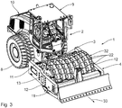
- a trained as a toy vehicle roller train comprises a front machine frame 1 and a rear frame part 2 and a vertical bending axis predetermining articulated joint 3, which connects the machine frame 1 and the frame part 2 hinged together.
- the machine frame 1 comprises a horizontally extending, rigid bearing frame 4 and a work roll 5, which is rotatably mounted in the bearing frame 4 about its horizontally extending longitudinal central axis 6 in a running direction 7.
- the longitudinal central axis 6 forms an axis of rotation.
- the frame part 2 is frosted. It includes two rotatably mounted wheels 8 and a driver's cab 9 and a rear engine compartment 10. In the engine compartment 10 is preferably no functioning engine, since the toy vehicle conveniently displaced by hand, in particular pushed.
- the bearing frame 4 comprises two outer cross members 11 and two cross members 11 interconnecting outer bearing support 12, which extend perpendicular to the cross members 11 and extending parallel to each other.
- the bearing carrier 12 extend parallel to a direction of travel 33 of the toy vehicle.
- a laterally limited receiving space 13 is formed for the work roll 5. It is appropriate when the bearing frame 4 is composed of two frame-like components, namely an upper frame part and a lower frame part.
- the arranged adjacent to the frame part 2 cross member 11 is articulated via the articulated joint 3 with the frame part 2.
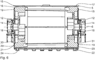
- Each bearing support 12 has substantially centrally a bearing means 14, which is formed according to this embodiment as a circular cross-sectional bearing receptacle.
- the work roll 5 comprises a work roll main body 15, which in turn comprises two circular disk-like, outer bearing discs 16 and a smooth bandage 17.
- the bearing discs 16 are parallel to each other. They are preferably non-rotatably connected to the smooth bandage 17. Conveniently, the bearing discs 16 are inserted into the smooth bandage 17 laterally outside.
- Each bearing disk 16 has a central bearing means 18, which according to this embodiment is designed as an axially outwardly projecting bearing journal and is adapted to the respective bearing means 14.
- Each bearing plate 16 also has, on the outside, a plurality of nose-like latching counter-elements 19, which each protrude in the direction of the longitudinal center axis 6 to the outside and one of the longitudinal center axis 6 facing locking mating surface 20 have.
- Each locking counter-element 19 has an outer, oblique latching counter-flank 21, which projects axially from radially outward in the direction of the longitudinal central axis 6 and extends straight up to the latching counter-surface 20.
- the locking counter-elements 19 have an identical angular distance about the longitudinal central axis 6 to each other. Overall, here are arranged on each bearing disc 16 six locking counter-elements 19.
- the locking counter-elements 19 are structurally identical.
- Fig. 1 In the described compactor, the so in Fig. 1 is shown, it is a game ready or playable toy vehicle.
- the compactor has on his wheels 8 and the work roll 5 while playing ground contact.
- the work roll 5 rotates about its longitudinal central axis 6 in the running direction 7.
- the latching counter-elements 19 are here without function or free. An opposing displacement of the roller is naturally possible alternatively, resulting in a reverse rotation of the work roll 5.
- a plurality of bandage lower bodies 22 can be detachably or detachably fastened to the work roll main body 15.
- the bandage lower body 22 are identical. They are elongated. Each bandage lower body 22 is formed substantially cup-shaped or segment-like.
- Each bandage lower body 22 has, for contact with the ground, a cup-shaped running region 23, from which a multiplicity of block-like stamping feet 24 project radially outward.
- Each bandage lower body 22 has a leading edge contour 25 in the running direction 7 and a trailing edge contour 26 trailing in the running direction 7.
- the edge contours 25, 26 of each bandage lower body 22 extend opposite one another. Between these lies in the running direction 7 in each case an identical distance.
- the edge contours 25, 26 have a course that deviates from a parallel to the longitudinal central axis 6 course.
- the leading edge contour 25 has a projecting in the running direction 7 central area, while the trailing edge contour 26 of this bandage lower body 22 has a corresponding bulge.
- Each leading edge contour 25 projects from axially laterally outside in the center in the running direction 7.
- Each bandage lower body 22 has axially laterally outside each a final contour 27 which extends between the edge contours 25, 26 of the respective bandage lower body 22.
- Each bandage lower body 22 thus has two end contours 27, which are opposite to each other and parallel to each other.
- an edge web 28 projects radially inwards. From each edge web 28 in turn jumps in the middle of a side part 31 radially inward before, which has a radially outwardly open latching receptacle 29.
- Each latching receptacle 29 is bounded by a radially inner latching surface 30, which is preferably flat and is turned radially outward in the assembled state of the respective bandage lower body 22.
- the locking receptacles 29 each have a width in the running direction 7, which corresponds approximately to the corresponding width of the respective locking counter-element 19.
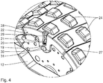
- the individual bandage lower bodies 22 are attached to the work roll main body 15 to form a padfoot bandage 32.
- the latching receptacles 29 are latched to the latching counter-elements 19.
- the latching mating surfaces 20 and the latching surfaces 30 of the respective bandage lower body 22 are arranged opposite one another, whereby the bandage lower body 22 are fixed radially outward on the work roll main body 15.
- the bandage lower body 22 are at their running area 23 outside of the smooth bandage 17, so that the smooth bandage 17 is surrounded by these and the bandage lower body 22 are fixed radially inward.
- the side parts 31 are arranged laterally outside with respect to the bearing discs 16, so that the bandage lower body 22 are axially fixed to the work roll main body 15.
- Each latching receptacle 29 has in the running direction 7 a width which corresponds approximately to the corresponding width of the latching counter element 19, so that there is essentially a backlash-free connection in the running direction 7 between the bearing discs 16 and the respective bandage lower body 22.
- the toy vehicle is also ready to play or playable with mounted padfoot bandage 32.
- padfoot bandage 32 When associated with the work roll main body 15 padfoot bandage 32 is the padfoot bandage 32 or stand their pestles 24 when playing in contact with the ground.
- the bandage lower body 22 together envelop the smooth bandage 17 and form an outer jacket.
- the smooth bandage 17 then has no contact with the ground while playing. It is then virtually functionless and lifted off the ground.
- the smooth bandage 17 is then within the padfoot bandage 32nd
- the bandage lower bodies 22 are removable from the work roll body 15 again to return to the "plain bandage" mode of operation to be able to.
- the corresponding side member 31 must be directed axially outward to dissolve the positive connection between the associated locking counter-element 19 and the locking receptacle 29.
Description
- Die Erfindung betrifft ein Spielfahrzeug, insbesondere ein Modell-Spielfahrzeug, gemäß dem Oberbegriff des Anspruchs 1. Insbesondere ermöglicht das Spielfahrzeug das Nachahmen der realen Umwelt. Spielfahrzeuge sind bekannt beispielsweise aus der
DE 10 2012 022 638 A1 , derDE 1 745 170 U und aus derDE 1 005 419 A . Aus derKR 20-2014-0005846 U
Der Erfindung liegt die Aufgabe zugrunde, ein Spielfahrzeug derart weiterzubilden, dass ein besonders vielfältiges und realistisches Spielerlebnis mit diesem möglich ist.
Diese Aufgabe wird erfindungsgemäß durch die in dem Anspruch 1 angegebenen Merkmale gelöst. Der Kern liegt darin, dass eine Montage-Bandage lösbar mit einem Arbeitswalzen-Grundkörper verbindbar ist bzw. von dem Arbeitswalzen-Grundkörper abnehmbar ist. Die Montage-Bandage ist also um den Arbeitswalzen-Grundkörper bzw. um die Arbeitswalze anordenbar. Sie ist montierbar und demontierbar. In montiertem Zustand bildet die Montage-Bandage quasi einen äußeren Mantel in Bezug auf die Arbeitswalze. - Ein Spielen mit dem Spielfahrzeug ist sowohl bei abgenommener Montage-Bandage als auch bei mit dem Arbeitswalzen-Grundkörper verbundener Montage-Bandage möglich. Bei abgenommener Montage-Bandage steht der Arbeitswalzen-Grundkörper mit seiner Mantelfläche bzw. Lauffläche beispielsweise in Form einer Glatt-Bandage oder Glattmantel-Bandage, in Bodenkontakt. Bei mit dem Arbeitswalzen-Grundkörper verbundener Montage-Bandage steht dagegen die Montage-Bandage selbst mit ihrer Lauffläche bzw. Mantelfläche in Bodenkontakt.
- Der Arbeitswalzen-Grundkörper hat vorzugsweise einen Außendurchmesser, der zwischen 4 cm und 20 cm, bevorzugter zwischen 6 cm und 15 cm, liegt.
- Vorzugsweise ist die Montage-Bandage aus Kunststoff gebildet. Sie ist vorzugsweise im Querschnitt ringförmig.
- Es ist zweckmäßig, wenn die Montage-Bandage von dem Arbeitswalzen-Grundkörper ohne Hilfsmittel, also werkzeuglos, abnehmbar bzw. demontierbar ist. Günstigerweise ist die Montage-Bandage auch ohne Hilfsmittel, also werkzeuglos, an dem Arbeitswalzen-Grundkörper anbringbar bzw. montierbar.
- Es ist von Vorteil, wenn die Arbeitswalze um eine Längsmittelachse drehbar ist. Dafür hat das Spielfahrzeug vorzugsweise mindestens eine entsprechende Lagereinrichtung.
- Günstigerweise sind der Arbeitswalzen-Grundkörper und die Montage-Bandage in montiertem Zustand der Montage-Bandage drehfest miteinander verbunden. Eine Relativ-Drehbewegung zwischen diesen ist dann unterbunden.
- Weitere vorteilhafte Ausgestaltungen der Erfindung sind in den Unteransprüchen angegeben.
- Die Ausgestaltung der Montage-Bandage, unterteilt in eine Mehrzahl von Bandagen-Unterkörper, die jeweils abnehmbar mit dem Arbeitswalzen-Grundkörper verbunden sind, erlaubt eine äußerst einfache Montage der Montage-Bandage an dem Arbeitswalzen-Grundkörper. Eine besonders einfache Demontage der Montage-Bandage ist ebenfalls möglich. Es ist zweckmäßig, wenn die Bandagen-Unterkörper identisch zueinander ausgebildet sind. Die Bandagen-Unterkörper sind vorzugsweise einzeln und unabhängig voneinander abnehmbar bzw. montierbar. Es können zwischen zwei und sechzehn Bandagen-Unterkörper vorgesehen sein.
- Die Bandagen-Unterkörper sind jeweils im Wesentlichen schalenartig. Sie sind vorzugsweise als Mantelsegmente ausgebildet. Jeder Bandagen-Unterkörper erstreckt sich günstigerweise in montiertem Zustand über einen Winkelbereich von 22,5° bis 180°, insbesondere von 45° bis 90°, um eine Längsmittelachse der Arbeitswalze. In montiertem Zustand der Montage-Bandage hat diese eine umlaufende geschlossene Mantelfläche.
- Zwischen benachbarten Bandagen-Unterkörpern kann zumindest bereichsweise ein Spalt vorliegen, sodass dort die Bandagen-Unterkörper voneinander getrennt sind. Benachbarte Bandagen-Unterkörper können einander zumindest aber auch bzw. alternativ bereichsweise randseitig berühren. Günstigerweise liegt jeder Bandagen-Unterkörper zumindest bereichsweise innenseitig auf dem Arbeitswalzen-Grundkörper auf.
- Die Ausgestaltung gemäß dem Unteranspruch 2 erlaubt eine schnelle Montage bzw. Demontage der Montage-Bandage. Insbesondere sind zwischen vier und acht Bandagen-Unterkörper vorgesehen.
- Gemäß dem Unteranspruch 4 sind die Bandagen-Unterkörper ausschließlich an dem Arbeitswalzen-Grundkörper befestigt. Eine Befestigung der Bandagen-Unterkörper aneinander bzw. untereinander bleibt somit aus.
- Die Ausgestaltung gemäß dem Unteranspruch 5 verhindert eine RelativBewegung zwischen benachbarten Bandagen-Unterkörpern in Richtung der Längsmittelachse der Arbeitswalze. Vorzugsweise greifen die benachbarten Bandagen-Unterkörper über ihre Randkonturen ineinander ein. Analoges gilt zu den Unteransprüchen 6 und 7.
- Die Rastverbindung gemäß dem Unteranspruch 8 erlaubt eine funktionssichere und schnelle Befestigung der Bandagen-Unterkörper an dem Arbeitswalzen-Grundkörper. Ein einfaches Entfernen bzw. Abnehmen der Bandagen-Unterkörper ist so ebenfalls möglich.
- Es ist von Vorteil, wenn das mindestens eine Rastelement gemäß dem Unteranspruch 9 mindestens eine Rastnase hat. Günstigerweise ist das mindestens eine Rast-Gegenelement als Aufnahme für das Rastelement ausgeführt. Eine umgekehrte Ausbildung ist alternativ möglich.
- Wenn die Montage-Bandage gemäß dem Unteranspruch 12 bzw. 13 montiert ist, ist die Betriebsweise "Stampffuß-Bandage" des Spielfahrzeugs möglich. Die Stampffuß-Bandage ist in der Realität für den Einsatz auf bindigen Böden vorgesehen. Die Stampffüße sind außenseitig angeordnet. Sie sind günstigerweise identisch ausgebildet. Es ist von Vorteil, wenn die Stampffüße in Reihen und/oder Spalten angeordnet sind. Alternativ kann die Montage-Bandage und/oder der Arbeitswalzen-Grundkörper als Gürtelradbandage, als Gitterradbandage, als Scheibenradbandage oder als Polygonbandage ausgebildet sein.
- Gemäß dem Unteranspruch 14 hat der Arbeitswalzen-Grundkörper eine Glatt-Bandage oder Glattmantel-Bandage, die im Querschnitt ringförmig ausgeführt ist und im Wesentlichen frei von Erhebungen bzw. Vertiefungen ist. Die Glatt-Bandage unterscheidet sich so konstruktiv von der Stampffuß-Bandage. Insbesondere unterscheidet sich die Glatt-Bandage in ihrer Oberfläche bzw. ihrem Oberflächenprofil von der Stampffuß-Bandage. Mit der Glatt-Bandage ist die Betriebsweise "Glatt-Bandage" des Spielfahrzeugs möglich. Die Glatt-Bandage ist in der Realität vorzugsweise zur Verdichtung von Asphalt oder nicht-bindigen Böden vorgesehen. Der Arbeitswalzen-Grundkörper umfasst vorzugsweise außerdem zwei Lagerscheiben.
- Das Spielfahrzeug gemäß dem Unteranspruch 15 ist als Baumaschine ausgebildet, das in der Realität im Wesentlichen eingesetzt wird, Böden bzw. Untergrund zu verdichten. Der Walzenzug hat vorzugsweise ein Maschinengestell zur Lagerung der Arbeitswalze und ein Gestellteil, das mit dem Maschinengestell in Verbindung steht. Es ist von Vorteil, wenn das Gestellteil des Walzenzugs eine Fahrerkabine umfasst bzw. trägt. Es ist zweckmäßig, wenn das Gestellteil beispielsweise auch einen Motorraum hat. Das Maschinengestell ist vorzugsweise vor dem Gestellteil angeordnet.
- Günstigerweise stehen das Maschinengestell und das Gestellteil in gelenkiger Verbindung miteinander, um ein Lenken des Spielfahrzeugs zu ermöglichen. Eine Knicklenkung kann so vorhanden sein. Alternativ sind das Maschinengestell und das Gestellteil starr miteinander verbunden. Das Gestellteil hat vorzugsweise mindestens ein Rad zum Bodenkontakt. Alternativ ist in/an dem Gestellteil eine weitere Arbeitswalze gelagert, mit deren Arbeitswalzen-Grundkörper eine weitere Montage-Bandage abnehmbar verbunden bzw. verbindbar ist.
- Nachfolgend wird unter Bezugnahme auf die beigefügte Zeichnung eine bevorzugte Ausführungsform der Erfindung beispielhaft beschrieben. Dabei zeigen:
- Fig. 1
- eine perspektivische Ansicht eines erfindungsgemäßen Spielfahrzeugs mit abgenommener Stampffuß-Bandage,
- Fig. 2
- eine perspektivische Ansicht des in
Fig. 1 dargestellten Spielfahrzeugs, wobei alle Bandagen-Unterkörper außer einem an dem Arbeitswalzen-Grundkörper befestigt sind, - Fig. 3
- eine perspektivische Ansicht des in
Fig. 1 bzw.Fig. 2 dargestellten Spielfahrzeugs, wobei alle Bandagen-Unterkörper an dem Arbeitswalzen-Grundkörper befestigt sind, - Fig. 4
- eine vergrößerte Detailansicht des in
Fig. 3 gezeigten Spielfahrzeugs, die die Befestigung eines Bandagen-Unterkörpers an dem Arbeitswalzen-Grundkörper zeigt, - Fig. 5
- eine Seitenansicht eines Maschinengestells des in
Fig. 2 dargestellten Spielfahrzeugs, - Fig. 6
- einen Längsschnitt durch das in
Fig. 5 dargestellte Maschinengestell entlang der Schnittlinie VI-VI inFig. 5 , und - Fig. 7
- eine Explosionsansicht des in
Fig. 5 und6 dargestellten Maschinengestells. - Zunächst Bezug nehmend auf die
Fig. 1 bis 3 umfasst ein als Spielfahrzeug ausgebildeter Walzenzug ein vorderes Maschinengestell 1 und ein hinteres Gestellteil 2 sowie ein eine vertikale Knickachse vorgebendes Knickgelenk 3, das das Maschinengestell 1 und das Gestellteil 2 gelenkig miteinander verbindet. - Das Maschinengestell 1 umfasst einen sich horizontal erstreckenden, starren Lagerrahmen 4 und eine Arbeitswalze 5, die in dem Lagerrahmen 4 um ihre horizontal verlaufende Längsmittelachse 6 in einer Laufrichtung 7 drehbar gelagert ist. Die Längsmittelachse 6 bildet eine Drehachse.
- Das Gestellteil 2 ist bereift. Es umfasst zwei drehbar gelagerte Räder 8 und eine Fahrerkabine 9 sowie einen hinteren Motorraum 10. In dem Motorraum 10 befindet sich vorzugsweise kein funktionsfähiger Motor, da das Spielfahrzeug günstigerweise händisch verlagert, insbesondere geschoben, wird.
- Der Lagerrahmen 4 umfasst zwei äußere Querträger 11 und zwei die Querträger 11 miteinander verbindende, äußere Lagerträger 12, die senkrecht zu den Querträgern 11 verlaufen und sich parallel zueinander erstrecken. Die Lagerträger 12 verlaufen parallel zu einer Fahrtrichtung 33 des Spielfahrzeugs. Durch die Querträger 11 und die Lagerträger 12 ist ein seitlich begrenzter Aufnahmeraum 13 für die Arbeitswalze 5 gebildet. Es ist zweckmäßig, wenn der Lagerrahmen 4 aus zwei rahmenartigen Bestandteilen zusammengesetzt ist, nämlich aus einem oberen Rahmenteil und einem unteren Rahmenteil.
- Der benachbart zu dem Gestellteil 2 angeordnete Querträger 11 ist über das Knickgelenk 3 mit dem Gestellteil 2 gelenkig verbunden.
- Jeder Lagerträger 12 weist im Wesentlichen mittig ein Lagermittel 14 auf, das gemäß dieser Ausführungsform als im Querschnitt kreisförmige Lageraufnahme ausgebildet ist.
- Die Arbeitswalze 5 umfasst einen Arbeitswalzen-Grundkörper 15, der wiederum zwei kreisscheibenartige, äußere Lagerscheiben 16 und eine Glatt-Bandage 17 umfasst.
- Die Lagerscheiben 16 verlaufen parallel zueinander. Sie sind vorzugsweise drehfest mit der Glatt-Bandage 17 verbunden. Günstigerweise sind die Lagerscheiben 16 in die Glatt-Bandage 17 seitlich außen eingesetzt. Jede Lagerscheibe 16 hat ein zentrales Lagermittel 18, das gemäß dieser Ausführungsform als axial nach außen vorspringender Lagerzapfen ausgebildet ist und an das jeweilige Lagermittel 14 angepasst ist. Jede Lagerscheibe 16 weist ferner stirnseitig außen mehrere nasenartige Rast-Gegenelemente 19 auf, die jeweils in Richtung der Längsmittelachse 6 nach seitlich außen vorspringen und eine der Längsmittelachse 6 zugewandte Rast-Gegenfläche 20 haben. Jedes Rast-Gegenelement 19 hat eine äußere, schräge Rast-Gegenflanke 21, die von radial außen in Richtung auf die Längsmittelachse 6 axial vorspringt und bis zu der Rast-Gegenfläche 20 gerade verläuft. Die Rast-Gegenelemente 19 haben einen identischen angularen Abstand um die Längsmittelachse 6 zueinander. Insgesamt sind hier an jeder Lagerscheibe 16 sechs Rast-Gegenelemente 19 angeordnet. Die Rast-Gegenelemente 19 sind konstruktiv identisch.
- Bei dem geschilderten Walzenzug, der so in
Fig. 1 dargestellt ist, handelt es sich um ein spielfertiges bzw. spielfähiges Spielfahrzeug. Der Walzenzug hat über seine Räder 8 und die Arbeitswalze 5 beim Spielen Bodenkontakt. Beim Verlagern des Walzenzugs in der Fahrtrichtung 33 dreht sich die Arbeitswalze 5 um ihre Längsmittelachse 6 in der Laufrichtung 7. Die Rast-Gegenelemente 19 sind hier ohne Funktion bzw. frei. Eine gegensinnige Verlagerung des Walzenzugs ist naturgemäß alternativ möglich, was zu einer umgekehrten Drehung der Arbeitswalze 5 führt. - Um von der Betriebsweise "Glatt-Bandage" zu der Betriebsweise "Stampffuß-Bandage" zu wechseln, sind an dem Arbeitswalzen-Grundkörper 15 mehrere Bandagen-Unterkörper 22 lösbar bzw. abnehmbar befestigbar.
- Die Bandagen-Unterkörper 22 sind identisch ausgeführt. Sie sind länglich. Jeder Bandagen-Unterkörper 22 ist im Wesentlichen schalenförmig bzw. segmentartig ausgebildet.
- Jeder Bandagen-Unterkörper 22 weist zum Bodenkontakt einen schalenförmigen Laufbereich 23 auf, von dem eine Vielzahl von blockartigen Stampffüßen 24 radial nach außen vorspringt. Jeder Bandagen-Unterkörper 22 hat eine in der Laufrichtung 7 vorauseilende Randkontur 25 und eine in der Laufrichtung 7 nacheilende Randkontur 26. Die Randkonturen 25, 26 von jedem Bandagen-Unterkörper 22 verlaufen einander gegenüberliegend. Zwischen diesen liegt in der Laufrichtung 7 jeweils ein identischer Abstand vor. Die Randkonturen 25, 26 haben einen Verlauf, der von einem zu der Längsmittelachse 6 parallelen Verlauf abweicht. Die vorauseilende Randkontur 25 hat einen in der Laufrichtung 7 vorspringenden zentralen Bereich, während die nacheilende Randkontur 26 dieses Bandagen-Unterkörpers 22 eine entsprechende Ausbuchtung hat. Jede vorauseilende Randkontur 25 springt von axial seitlich außen mittig in der Laufrichtung 7 vor.
- Jeder Bandagen-Unterkörper 22 hat axial seitlich außen jeweils eine Endkontur 27, die sich zwischen den Randkonturen 25, 26 des jeweiligen Bandagen-Unterkörpers 22 erstreckt. Jeder Bandagen-Unterkörper 22 weist somit zwei Endkonturen 27 auf, die einander gegenüberliegen und parallel zueinander verlaufen. Im Bereich jeder Endkontur 27 springt ein Randsteg 28 radial nach innen vor. Von jedem Randsteg 28 wiederum springt mittig ein Seitenteil 31 nach radial innen vor, das eine nach radial außen offene Rastaufnahme 29 aufweist. Jede Rastaufnahme 29 ist durch eine radial innere Rastfläche 30 begrenzt, die vorzugsweise eben ist und in montiertem Zustand des jeweiligen Bandagen-Unterkörpers 22 nach radial außen gewandt ist. Die Rastaufnahmen 29 haben jeweils eine Weite in der Laufrichtung 7, die in etwa der entsprechenden Weite des jeweiligen Rast-Gegenelements 19 entspricht.
- Für den Einsatz des Spielfahrzeugs als "Stampffuß-Bandage" werden die einzelnen Bandagen-Unterkörper 22 unter Bildung einer Stampffuß-Bandage 32 an dem Arbeitswalzen-Grundkörper 15 befestigt. Dabei werden die Rastaufnahmen 29 mit den Rast-Gegenelementen 19 verrastet. In verrastetem Zustand sind die Rast-Gegenflächen 20 und die Rastflächen 30 des jeweiligen Bandagen-Unterkörpers 22 einander gegenüberliegend angeordnet, wodurch die Bandagen-Unterkörper 22 nach radial außen an dem Arbeitswalzen-Grundkörper 15 fixiert sind. Die Bandagen-Unterkörper 22 liegen bei ihrem Laufbereich 23 außen an der Glatt-Bandage 17 an, sodass die Glatt-Bandage 17 von diesen umgeben ist und die Bandagen-Unterkörper 22 nach radial innen fixiert sind. Die Seitenteile 31 sind seitlich außen in Bezug auf die Lagerscheiben 16 angeordnet, sodass die Bandagen-Unterkörper 22 an dem Arbeitswalzen-Grundkörper 15 axial fixiert sind. Jede Rastaufnahme 29 weist in der Laufrichtung 7 eine Weite auf, die in etwa der entsprechenden Weite des Rast-Gegenelements 19 entspricht, sodass in der Laufrichtung 7 zwischen den Lagerscheiben 16 und dem jeweiligen Bandagen-Unterkörper 22 im Wesentlichen eine spielfreie Verbindung vorliegt. Das Spielfahrzeug ist auch mit montierter Stampffuß-Bandage 32 spielfertig bzw. spielfähig.
- Bei der Montage der Bandagen-Unterkörper 22 gleiten die Seitenteile 31 auf der Rast-Gegenflanke 21 von radial außen nach radial innen und werden dabei axial nach außen ausgelenkt bis die Rast-Gegenfläche 20 erreicht ist. Die Seitenteile 31 federn dann in ihre unausgelenkte Stellung zurück, wordurch die beschriebene Rastverbindung zwischen Bandagen-Unterkörper 22 und Arbeitswalzen-Grundkörper 15 entsteht. Benachbarte Bandagen-Unterkörper 22 sind aneinander unbefestigt.
- Bei mit dem Arbeitswalzen-Grundkörper 15 verbundener Stampffuß-Bandage 32 steht die Stampffuß-Bandage 32 bzw. stehen deren Stampffüße 24 beim Spielen in Bodenkontakt. Die Bandagen-Unterkörper 22 umhüllen zusammen die Glatt-Bandage 17 und bilden einen äußeren Mantel. Die Glatt-Bandage 17 hat dann beim Spielen keinen Bodenkontakt. Sie ist dann quasi funktionslos und von dem Boden abgehoben. Die Glatt-Bandage 17 befindet sich dann innerhalb der Stampffuß-Bandage 32.
- Die Bandagen-Unterkörper 22 sind von dem Arbeitswalzen-Grundkörper 15 wieder entfernbar, um zu der Betriebsweise "Glatt-Bandage" zurückkehren zu können. Zum Lösen der Rastverbindung zwischen Bandagen-Unterkörper 22 und Arbeitswalzen-Grundkörper 15 muss das entsprechende Seitenelement 31 nach axial außen gelenkt werden, um die formschlüssige Verbindung zwischen dem zugehörigen Rast-Gegenelement 19 und der Rastaufnahme 29 aufzulösen.
- Die verwendeten Begriffe "radial" und "axial" beziehen sich im Allgemeinen auf die Längsmittelachse 6.
Claims (15)
- Spielfahrzeug,a) mit einer drehbar gelagerten Arbeitswalze (5) zum Bodenkontakt,i. wobei die Arbeitswalze (5) einen Arbeitswalzen-Grundkörper (15) umfasst,gekennzeichnet durchb) eine Montage-Bandage (32), diei. in montiertem Zustand den Arbeitswalzen-Grundkörper (15) mantelartig umgibt,ii. abnehmbar mit dem Arbeitswalzen-Grundkörper (15) verbunden ist, sodass sich sowohl bei abgenommener als auch bei mit dem Arbeitswalzen-Grundkörper (15) verbundener Montage-Bandage (32) ein spielfertiges Spielfahrzeug ergibt, undiii. in eine Mehrzahl von Bandagen-Unterkörper (22) unterteilt ist, die jeweils abnehmbar mit dem Arbeitswalzen-Grundkörper (15) verbunden sind.
- Spielfahrzeug nach Anspruch 1, dadurch gekennzeichnet, dass mehr als zwei Bandagen-Unterkörper (22) vorgesehen sind.
- Spielfahrzeug nach Anspruch 1 oder 2, dadurch gekennzeichnet, dass die Montage-Bandage (32) aus Kunststoff gebildet ist.
- Spielfahrzeug nach einem der Ansprüche 1 bis 3, dadurch gekennzeichnet, dass die Bandagen-Unterkörper (22) ausschließlich an dem Arbeitswalzen-Grundkörper (15) befestigt sind.
- Spielfahrzeug nach einem der Ansprüche 1 bis 4, dadurch gekennzeichnet, dass die Bandagen-Unterkörper (22) in Bezug auf eine Laufrichtung (7) der Arbeitswalze (5) vorauseilende und nacheilende Randkonturen (25, 26) aufweisen, deren Verlauf von einem zu einer Längsmittelachse (6) der Arbeitswalze (5) parallelen Verlauf zumindest bereichsweise abweicht.
- Spielfahrzeug nach Anspruch 5, dadurch gekennzeichnet, dass die vorauseilenden und nacheilenden Randkonturen (25, 26) benachbarter Bandagen-Unterkörper (22) komplementär zueinander ausgebildet sind.
- Spielfahrzeug nach Anspruch 5 oder 6, dadurch gekennzeichnet, dass die vorauseilenden und/oder nacheilenden Randkonturen (25, 26) Randbereiche aufweisen, die sich schräg und/oder senkrecht zueinander erstrecken oder gekrümmt verlaufen.
- Spielfahrzeug nach einem der Ansprüche 1 bis 7, dadurch gekennzeichnet, dass die Bandagen-Unterkörper (22) mit dem Arbeitswalzen-Grundkörper (15) über eine Rastverbindung verrastet sind.
- Spielfahrzeug nach Anspruch 8, dadurch gekennzeichnet, dass an jedem Bandagen-Unterkörper (22) mindestens ein Rastelement (29) und an dem Arbeitswalzen-Grundkörper (15) mindestens ein Rast-Gegenelement (19) zur Verrastung mit dem mindestens einen Rastelement (29) des jeweiligen Bandagen-Unterkörpers (22) angeordnet ist.
- Spielfahrzeug nach Anspruch 9, dadurch gekennzeichnet, dass das mindestens eine Rastelement (29) von einem Laufbereich (23) des jeweiligen Bandagen-Unterkörpers (22) nach radial innen vorspringt.
- Spielfahrzeug nach Anspruch 9 oder 10, dadurch gekennzeichnet, dass das mindestens eine Rastelement (29) in Bezug auf eine Längsmittelachse (6) der Montage-Bandage (32) axial seitlich außen angeordnet ist.
- Spielfahrzeug nach einem der vorherigen Ansprüche, dadurch gekennzeichnet, dass die Montage-Bandage (32) als Stampffuß-Bandage ausgebildet ist.
- Spielfahrzeug nach Anspruch 12, dadurch gekennzeichnet, dass die Montage-Bandage (32) eine Vielzahl radial nach außen vorspringender Stampffüße (24) aufweist.
- Spielfahrzeug nach einem der vorherigen Ansprüche, dadurch gekennzeichnet, dass der Arbeitswalzen-Grundkörper (15) eine Glatt-Bandage (17) umfasst.
- Spielfahrzeug nach einem der vorherigen Ansprüche, dadurch gekennzeichnet, dass dieses als Walzenzug ausgebildet ist.
Applications Claiming Priority (1)
| Application Number | Priority Date | Filing Date | Title |
|---|---|---|---|
| DE202015100263.7U DE202015100263U1 (de) | 2015-01-21 | 2015-01-21 | Spielfahrzeug |
Publications (2)
| Publication Number | Publication Date |
|---|---|
| EP3047886A1 EP3047886A1 (de) | 2016-07-27 |
| EP3047886B1 true EP3047886B1 (de) | 2018-07-18 |
Family
ID=54754554
Family Applications (1)
| Application Number | Title | Priority Date | Filing Date |
|---|---|---|---|
| EP15197201.5A Not-in-force EP3047886B1 (de) | 2015-01-21 | 2015-12-01 | Spielfahrzeug |
Country Status (2)
| Country | Link |
|---|---|
| EP (1) | EP3047886B1 (de) |
| DE (1) | DE202015100263U1 (de) |
Family Cites Families (5)
| Publication number | Priority date | Publication date | Assignee | Title |
|---|---|---|---|---|
| US1764733A (en) * | 1930-02-24 | 1930-06-17 | Murray Ohio Mfg Co | Wheeled toy |
| DE1005419B (de) * | 1955-07-06 | 1957-03-28 | Tipp & Co | Umsteuerung fuer Fahrerfiguren in Spielzeugfahrzeugen |
| DE1745170U (de) * | 1957-02-23 | 1957-05-16 | Klebes & Co K G A | Fahrspielzeug mit walzenfoermigen radern. |
| DE102012022638B4 (de) * | 2012-11-20 | 2017-05-24 | Franz Schneider Gmbh & Co. Kg | Kehrgerät für ein Kinderfahrzeug, insbesondere für ein Tretfahrzeug |
| KR20140005846U (ko) * | 2013-05-09 | 2014-11-19 | 주식회사 대성토이즈 | 공룡 겸용 중장비 완구 |
-
2015
- 2015-01-21 DE DE202015100263.7U patent/DE202015100263U1/de not_active Expired - Lifetime
- 2015-12-01 EP EP15197201.5A patent/EP3047886B1/de not_active Not-in-force
Non-Patent Citations (1)
| Title |
|---|
| None * |
Also Published As
| Publication number | Publication date |
|---|---|
| DE202015100263U1 (de) | 2016-04-25 |
| EP3047886A1 (de) | 2016-07-27 |
Similar Documents
| Publication | Publication Date | Title |
|---|---|---|
| DE102011053903A1 (de) | Mecanumrad sowie Mecanumradfahrzeug | |
| DE2721388A1 (de) | Zweiraedrige schwenkrolle, insbesondere fuer moebelfuesse | |
| DE60112072T2 (de) | Selbstfahrender Wagen, der sich in einem zylindrischen Stollen zu bewegen vermag | |
| DE202018105819U1 (de) | Rollbrett | |
| DE2817523A1 (de) | Fahrzeug mit raupenband | |
| EP1713713B1 (de) | Rollvorrichtung fur ein defektes rad eines kraftfahrzeugs | |
| DE102018219575A1 (de) | Reinigungsroboter | |
| EP3047886B1 (de) | Spielfahrzeug | |
| EP1513985B1 (de) | Bodenverdichtungsvorrichtung mit fahrwerk | |
| EP2907415A1 (de) | Laufkörper für eine auf Waren wirkende Drückeinrichtung eines Rutschregales sowie Drückeinrichtung | |
| DE102004007188A1 (de) | Zerlegbare Rolle | |
| DE2724106A1 (de) | Bodenzugvorrichtung | |
| DE102007031237A1 (de) | Kippwinkel-gelenktes Rollgerät mit versetzten Rollen | |
| DE102015220497A1 (de) | Raupenfahrzeug, Verfahren zum Betreiben eines Raupenfahrzeugs | |
| DE2711561B2 (de) | Kraftfahrzeugrad mit einer selbsttätigen Auswuchtvorrichtung | |
| WO2002082880A2 (de) | Vorrichtung zum verfestigen des bodens | |
| DE102014106953A1 (de) | Fahrwerk einer landwirtschaftlichen Maschine | |
| AT407817B (de) | Vorrichtung zur bodenbearbeitung | |
| DE60102095T2 (de) | Motorangetriebene Kehrmaschine | |
| DE2805138A1 (de) | Aus kunststoff gespritztes und zerlegbares spielzeugauto | |
| EP0155929B1 (de) | Fahrbares Bodenverdichtungsgerät | |
| DE3426330A1 (de) | Rad mit o-ring | |
| EP1904191B1 (de) | Rad | |
| DE202004005818U1 (de) | Bodenstaubsauger | |
| DE4406802C2 (de) | Nockenwalze |
Legal Events
| Date | Code | Title | Description |
|---|---|---|---|
| PUAI | Public reference made under article 153(3) epc to a published international application that has entered the european phase |
Free format text: ORIGINAL CODE: 0009012 |
|
| AK | Designated contracting states |
Kind code of ref document: A1 Designated state(s): AL AT BE BG CH CY CZ DE DK EE ES FI FR GB GR HR HU IE IS IT LI LT LU LV MC MK MT NL NO PL PT RO RS SE SI SK SM TR |
|
| AX | Request for extension of the european patent |
Extension state: BA ME |
|
| 17P | Request for examination filed |
Effective date: 20161223 |
|
| RBV | Designated contracting states (corrected) |
Designated state(s): AL AT BE BG CH CY CZ DE DK EE ES FI FR GB GR HR HU IE IS IT LI LT LU LV MC MK MT NL NO PL PT RO RS SE SI SK SM TR |
|
| GRAP | Despatch of communication of intention to grant a patent |
Free format text: ORIGINAL CODE: EPIDOSNIGR1 |
|
| INTG | Intention to grant announced |
Effective date: 20180313 |
|
| GRAS | Grant fee paid |
Free format text: ORIGINAL CODE: EPIDOSNIGR3 |
|
| GRAA | (expected) grant |
Free format text: ORIGINAL CODE: 0009210 |
|
| AK | Designated contracting states |
Kind code of ref document: B1 Designated state(s): AL AT BE BG CH CY CZ DE DK EE ES FI FR GB GR HR HU IE IS IT LI LT LU LV MC MK MT NL NO PL PT RO RS SE SI SK SM TR |
|
| REG | Reference to a national code |
Ref country code: GB Ref legal event code: FG4D Free format text: NOT ENGLISH |
|
| REG | Reference to a national code |
Ref country code: CH Ref legal event code: EP |
|
| REG | Reference to a national code |
Ref country code: IE Ref legal event code: FG4D Free format text: LANGUAGE OF EP DOCUMENT: GERMAN |
|
| REG | Reference to a national code |
Ref country code: AT Ref legal event code: REF Ref document number: 1018744 Country of ref document: AT Kind code of ref document: T Effective date: 20180815 |
|
| REG | Reference to a national code |
Ref country code: DE Ref legal event code: R096 Ref document number: 502015005113 Country of ref document: DE |
|
| REG | Reference to a national code |
Ref country code: NL Ref legal event code: FP |
|
| REG | Reference to a national code |
Ref country code: LT Ref legal event code: MG4D |
|
| PG25 | Lapsed in a contracting state [announced via postgrant information from national office to epo] |
Ref country code: SE Free format text: LAPSE BECAUSE OF FAILURE TO SUBMIT A TRANSLATION OF THE DESCRIPTION OR TO PAY THE FEE WITHIN THE PRESCRIBED TIME-LIMIT Effective date: 20180718 Ref country code: BG Free format text: LAPSE BECAUSE OF FAILURE TO SUBMIT A TRANSLATION OF THE DESCRIPTION OR TO PAY THE FEE WITHIN THE PRESCRIBED TIME-LIMIT Effective date: 20181018 Ref country code: NO Free format text: LAPSE BECAUSE OF FAILURE TO SUBMIT A TRANSLATION OF THE DESCRIPTION OR TO PAY THE FEE WITHIN THE PRESCRIBED TIME-LIMIT Effective date: 20181018 Ref country code: RS Free format text: LAPSE BECAUSE OF FAILURE TO SUBMIT A TRANSLATION OF THE DESCRIPTION OR TO PAY THE FEE WITHIN THE PRESCRIBED TIME-LIMIT Effective date: 20180718 Ref country code: GR Free format text: LAPSE BECAUSE OF FAILURE TO SUBMIT A TRANSLATION OF THE DESCRIPTION OR TO PAY THE FEE WITHIN THE PRESCRIBED TIME-LIMIT Effective date: 20181019 Ref country code: LT Free format text: LAPSE BECAUSE OF FAILURE TO SUBMIT A TRANSLATION OF THE DESCRIPTION OR TO PAY THE FEE WITHIN THE PRESCRIBED TIME-LIMIT Effective date: 20180718 Ref country code: PL Free format text: LAPSE BECAUSE OF FAILURE TO SUBMIT A TRANSLATION OF THE DESCRIPTION OR TO PAY THE FEE WITHIN THE PRESCRIBED TIME-LIMIT Effective date: 20180718 Ref country code: FI Free format text: LAPSE BECAUSE OF FAILURE TO SUBMIT A TRANSLATION OF THE DESCRIPTION OR TO PAY THE FEE WITHIN THE PRESCRIBED TIME-LIMIT Effective date: 20180718 Ref country code: IS Free format text: LAPSE BECAUSE OF FAILURE TO SUBMIT A TRANSLATION OF THE DESCRIPTION OR TO PAY THE FEE WITHIN THE PRESCRIBED TIME-LIMIT Effective date: 20181118 |
|
| PG25 | Lapsed in a contracting state [announced via postgrant information from national office to epo] |
Ref country code: LV Free format text: LAPSE BECAUSE OF FAILURE TO SUBMIT A TRANSLATION OF THE DESCRIPTION OR TO PAY THE FEE WITHIN THE PRESCRIBED TIME-LIMIT Effective date: 20180718 Ref country code: AL Free format text: LAPSE BECAUSE OF FAILURE TO SUBMIT A TRANSLATION OF THE DESCRIPTION OR TO PAY THE FEE WITHIN THE PRESCRIBED TIME-LIMIT Effective date: 20180718 Ref country code: HR Free format text: LAPSE BECAUSE OF FAILURE TO SUBMIT A TRANSLATION OF THE DESCRIPTION OR TO PAY THE FEE WITHIN THE PRESCRIBED TIME-LIMIT Effective date: 20180718 |
|
| REG | Reference to a national code |
Ref country code: DE Ref legal event code: R097 Ref document number: 502015005113 Country of ref document: DE |
|
| PG25 | Lapsed in a contracting state [announced via postgrant information from national office to epo] |
Ref country code: IT Free format text: LAPSE BECAUSE OF FAILURE TO SUBMIT A TRANSLATION OF THE DESCRIPTION OR TO PAY THE FEE WITHIN THE PRESCRIBED TIME-LIMIT Effective date: 20180718 Ref country code: CZ Free format text: LAPSE BECAUSE OF FAILURE TO SUBMIT A TRANSLATION OF THE DESCRIPTION OR TO PAY THE FEE WITHIN THE PRESCRIBED TIME-LIMIT Effective date: 20180718 Ref country code: EE Free format text: LAPSE BECAUSE OF FAILURE TO SUBMIT A TRANSLATION OF THE DESCRIPTION OR TO PAY THE FEE WITHIN THE PRESCRIBED TIME-LIMIT Effective date: 20180718 Ref country code: RO Free format text: LAPSE BECAUSE OF FAILURE TO SUBMIT A TRANSLATION OF THE DESCRIPTION OR TO PAY THE FEE WITHIN THE PRESCRIBED TIME-LIMIT Effective date: 20180718 Ref country code: ES Free format text: LAPSE BECAUSE OF FAILURE TO SUBMIT A TRANSLATION OF THE DESCRIPTION OR TO PAY THE FEE WITHIN THE PRESCRIBED TIME-LIMIT Effective date: 20180718 |
|
| PLBE | No opposition filed within time limit |
Free format text: ORIGINAL CODE: 0009261 |
|
| STAA | Information on the status of an ep patent application or granted ep patent |
Free format text: STATUS: NO OPPOSITION FILED WITHIN TIME LIMIT |
|
| PG25 | Lapsed in a contracting state [announced via postgrant information from national office to epo] |
Ref country code: SK Free format text: LAPSE BECAUSE OF FAILURE TO SUBMIT A TRANSLATION OF THE DESCRIPTION OR TO PAY THE FEE WITHIN THE PRESCRIBED TIME-LIMIT Effective date: 20180718 Ref country code: SM Free format text: LAPSE BECAUSE OF FAILURE TO SUBMIT A TRANSLATION OF THE DESCRIPTION OR TO PAY THE FEE WITHIN THE PRESCRIBED TIME-LIMIT Effective date: 20180718 Ref country code: DK Free format text: LAPSE BECAUSE OF FAILURE TO SUBMIT A TRANSLATION OF THE DESCRIPTION OR TO PAY THE FEE WITHIN THE PRESCRIBED TIME-LIMIT Effective date: 20180718 |
|
| 26N | No opposition filed |
Effective date: 20190423 |
|
| REG | Reference to a national code |
Ref country code: CH Ref legal event code: PL |
|
| PG25 | Lapsed in a contracting state [announced via postgrant information from national office to epo] |
Ref country code: SI Free format text: LAPSE BECAUSE OF FAILURE TO SUBMIT A TRANSLATION OF THE DESCRIPTION OR TO PAY THE FEE WITHIN THE PRESCRIBED TIME-LIMIT Effective date: 20180718 Ref country code: MC Free format text: LAPSE BECAUSE OF FAILURE TO SUBMIT A TRANSLATION OF THE DESCRIPTION OR TO PAY THE FEE WITHIN THE PRESCRIBED TIME-LIMIT Effective date: 20180718 Ref country code: LU Free format text: LAPSE BECAUSE OF NON-PAYMENT OF DUE FEES Effective date: 20181201 |
|
| REG | Reference to a national code |
Ref country code: IE Ref legal event code: MM4A |
|
| PG25 | Lapsed in a contracting state [announced via postgrant information from national office to epo] |
Ref country code: IE Free format text: LAPSE BECAUSE OF NON-PAYMENT OF DUE FEES Effective date: 20181201 |
|
| PG25 | Lapsed in a contracting state [announced via postgrant information from national office to epo] |
Ref country code: CH Free format text: LAPSE BECAUSE OF NON-PAYMENT OF DUE FEES Effective date: 20181231 Ref country code: LI Free format text: LAPSE BECAUSE OF NON-PAYMENT OF DUE FEES Effective date: 20181231 |
|
| PG25 | Lapsed in a contracting state [announced via postgrant information from national office to epo] |
Ref country code: MT Free format text: LAPSE BECAUSE OF FAILURE TO SUBMIT A TRANSLATION OF THE DESCRIPTION OR TO PAY THE FEE WITHIN THE PRESCRIBED TIME-LIMIT Effective date: 20180718 |
|
| PG25 | Lapsed in a contracting state [announced via postgrant information from national office to epo] |
Ref country code: TR Free format text: LAPSE BECAUSE OF FAILURE TO SUBMIT A TRANSLATION OF THE DESCRIPTION OR TO PAY THE FEE WITHIN THE PRESCRIBED TIME-LIMIT Effective date: 20180718 |
|
| PG25 | Lapsed in a contracting state [announced via postgrant information from national office to epo] |
Ref country code: PT Free format text: LAPSE BECAUSE OF FAILURE TO SUBMIT A TRANSLATION OF THE DESCRIPTION OR TO PAY THE FEE WITHIN THE PRESCRIBED TIME-LIMIT Effective date: 20180718 |
|
| PG25 | Lapsed in a contracting state [announced via postgrant information from national office to epo] |
Ref country code: HU Free format text: LAPSE BECAUSE OF FAILURE TO SUBMIT A TRANSLATION OF THE DESCRIPTION OR TO PAY THE FEE WITHIN THE PRESCRIBED TIME-LIMIT; INVALID AB INITIO Effective date: 20151201 Ref country code: MK Free format text: LAPSE BECAUSE OF NON-PAYMENT OF DUE FEES Effective date: 20180718 Ref country code: CY Free format text: LAPSE BECAUSE OF FAILURE TO SUBMIT A TRANSLATION OF THE DESCRIPTION OR TO PAY THE FEE WITHIN THE PRESCRIBED TIME-LIMIT Effective date: 20180718 |
|
| PGFP | Annual fee paid to national office [announced via postgrant information from national office to epo] |
Ref country code: FR Payment date: 20211220 Year of fee payment: 7 Ref country code: GB Payment date: 20211222 Year of fee payment: 7 |
|
| REG | Reference to a national code |
Ref country code: AT Ref legal event code: MM01 Ref document number: 1018744 Country of ref document: AT Kind code of ref document: T Effective date: 20201201 |
|
| PGFP | Annual fee paid to national office [announced via postgrant information from national office to epo] |
Ref country code: BE Payment date: 20211217 Year of fee payment: 7 |
|
| PGFP | Annual fee paid to national office [announced via postgrant information from national office to epo] |
Ref country code: NL Payment date: 20211217 Year of fee payment: 7 |
|
| PG25 | Lapsed in a contracting state [announced via postgrant information from national office to epo] |
Ref country code: AT Free format text: LAPSE BECAUSE OF NON-PAYMENT OF DUE FEES Effective date: 20201201 |
|
| PGFP | Annual fee paid to national office [announced via postgrant information from national office to epo] |
Ref country code: DE Payment date: 20220225 Year of fee payment: 7 |
|
| REG | Reference to a national code |
Ref country code: DE Ref legal event code: R119 Ref document number: 502015005113 Country of ref document: DE |
|
| REG | Reference to a national code |
Ref country code: NL Ref legal event code: MM Effective date: 20230101 |
|
| GBPC | Gb: european patent ceased through non-payment of renewal fee |
Effective date: 20221201 |
|
| REG | Reference to a national code |
Ref country code: BE Ref legal event code: MM Effective date: 20221231 |
|
| PG25 | Lapsed in a contracting state [announced via postgrant information from national office to epo] |
Ref country code: NL Free format text: LAPSE BECAUSE OF NON-PAYMENT OF DUE FEES Effective date: 20230101 |
|
| PG25 | Lapsed in a contracting state [announced via postgrant information from national office to epo] |
Ref country code: GB Free format text: LAPSE BECAUSE OF NON-PAYMENT OF DUE FEES Effective date: 20221201 Ref country code: DE Free format text: LAPSE BECAUSE OF NON-PAYMENT OF DUE FEES Effective date: 20230701 |
|
| PG25 | Lapsed in a contracting state [announced via postgrant information from national office to epo] |
Ref country code: FR Free format text: LAPSE BECAUSE OF NON-PAYMENT OF DUE FEES Effective date: 20221231 Ref country code: BE Free format text: LAPSE BECAUSE OF NON-PAYMENT OF DUE FEES Effective date: 20221231 |