EP3045196B1 - Ein- oder mehrstufengebläse und verschachtelte(s) spiralgehäuse und/oder impeller dafür - Google Patents
Ein- oder mehrstufengebläse und verschachtelte(s) spiralgehäuse und/oder impeller dafür Download PDFInfo
- Publication number
- EP3045196B1 EP3045196B1 EP16153742.8A EP16153742A EP3045196B1 EP 3045196 B1 EP3045196 B1 EP 3045196B1 EP 16153742 A EP16153742 A EP 16153742A EP 3045196 B1 EP3045196 B1 EP 3045196B1
- Authority
- EP
- European Patent Office
- Prior art keywords
- shroud
- impeller
- pressure device
- airway pressure
- vane
- Prior art date
- Legal status (The legal status is an assumption and is not a legal conclusion. Google has not performed a legal analysis and makes no representation as to the accuracy of the status listed.)
- Not-in-force
Links
- 239000000463 material Substances 0.000 claims description 12
- 239000004743 Polypropylene Substances 0.000 claims description 6
- 229920000515 polycarbonate Polymers 0.000 claims description 6
- 239000004417 polycarbonate Substances 0.000 claims description 6
- -1 polypropylene Polymers 0.000 claims description 4
- 229920001155 polypropylene Polymers 0.000 claims description 4
- 238000002560 therapeutic procedure Methods 0.000 claims description 2
- 239000007789 gas Substances 0.000 description 53
- 238000013461 design Methods 0.000 description 13
- 230000002093 peripheral effect Effects 0.000 description 12
- 230000000712 assembly Effects 0.000 description 7
- 238000000429 assembly Methods 0.000 description 7
- 230000008901 benefit Effects 0.000 description 7
- 238000004519 manufacturing process Methods 0.000 description 5
- 208000001797 obstructive sleep apnea Diseases 0.000 description 5
- 230000002829 reductive effect Effects 0.000 description 5
- 238000009423 ventilation Methods 0.000 description 5
- 238000000034 method Methods 0.000 description 4
- 230000029058 respiratory gaseous exchange Effects 0.000 description 4
- 229920002379 silicone rubber Polymers 0.000 description 4
- 239000004945 silicone rubber Substances 0.000 description 4
- 230000007704 transition Effects 0.000 description 4
- 229910052782 aluminium Inorganic materials 0.000 description 3
- XAGFODPZIPBFFR-UHFFFAOYSA-N aluminium Chemical compound [Al] XAGFODPZIPBFFR-UHFFFAOYSA-N 0.000 description 3
- 238000010276 construction Methods 0.000 description 3
- 230000008030 elimination Effects 0.000 description 3
- 238000003379 elimination reaction Methods 0.000 description 3
- 230000003434 inspiratory effect Effects 0.000 description 3
- 230000004044 response Effects 0.000 description 3
- FYYHWMGAXLPEAU-UHFFFAOYSA-N Magnesium Chemical compound [Mg] FYYHWMGAXLPEAU-UHFFFAOYSA-N 0.000 description 2
- 239000000853 adhesive Substances 0.000 description 2
- 230000001070 adhesive effect Effects 0.000 description 2
- 239000004020 conductor Substances 0.000 description 2
- 238000013016 damping Methods 0.000 description 2
- 229920001971 elastomer Polymers 0.000 description 2
- 229920005570 flexible polymer Polymers 0.000 description 2
- 239000003365 glass fiber Substances 0.000 description 2
- 238000002955 isolation Methods 0.000 description 2
- 229910052749 magnesium Inorganic materials 0.000 description 2
- 239000011777 magnesium Substances 0.000 description 2
- 238000000465 moulding Methods 0.000 description 2
- 230000036961 partial effect Effects 0.000 description 2
- 239000004033 plastic Substances 0.000 description 2
- 229920003023 plastic Polymers 0.000 description 2
- 229920000379 polypropylene carbonate Polymers 0.000 description 2
- 229920001296 polysiloxane Polymers 0.000 description 2
- 230000008569 process Effects 0.000 description 2
- 230000002787 reinforcement Effects 0.000 description 2
- 230000000241 respiratory effect Effects 0.000 description 2
- 208000023504 respiratory system disease Diseases 0.000 description 2
- 238000007788 roughening Methods 0.000 description 2
- 239000005060 rubber Substances 0.000 description 2
- 238000007789 sealing Methods 0.000 description 2
- 229920002725 thermoplastic elastomer Polymers 0.000 description 2
- XLYOFNOQVPJJNP-UHFFFAOYSA-N water Substances O XLYOFNOQVPJJNP-UHFFFAOYSA-N 0.000 description 2
- 206010007559 Cardiac failure congestive Diseases 0.000 description 1
- 206010014561 Emphysema Diseases 0.000 description 1
- 206010019280 Heart failures Diseases 0.000 description 1
- 208000008589 Obesity Diseases 0.000 description 1
- 208000006011 Stroke Diseases 0.000 description 1
- 230000005534 acoustic noise Effects 0.000 description 1
- 239000004411 aluminium Substances 0.000 description 1
- 238000013459 approach Methods 0.000 description 1
- QVGXLLKOCUKJST-UHFFFAOYSA-N atomic oxygen Chemical compound [O] QVGXLLKOCUKJST-UHFFFAOYSA-N 0.000 description 1
- 238000005452 bending Methods 0.000 description 1
- 238000004891 communication Methods 0.000 description 1
- 208000012696 congenital leptin deficiency Diseases 0.000 description 1
- 230000008878 coupling Effects 0.000 description 1
- 238000010168 coupling process Methods 0.000 description 1
- 238000005859 coupling reaction Methods 0.000 description 1
- 230000005574 cross-species transmission Effects 0.000 description 1
- 230000003247 decreasing effect Effects 0.000 description 1
- 206010012601 diabetes mellitus Diseases 0.000 description 1
- 230000000694 effects Effects 0.000 description 1
- 239000012530 fluid Substances 0.000 description 1
- 238000010348 incorporation Methods 0.000 description 1
- 238000001746 injection moulding Methods 0.000 description 1
- 238000003780 insertion Methods 0.000 description 1
- 230000037431 insertion Effects 0.000 description 1
- 239000003562 lightweight material Substances 0.000 description 1
- 230000000670 limiting effect Effects 0.000 description 1
- 229910052751 metal Inorganic materials 0.000 description 1
- 239000002184 metal Substances 0.000 description 1
- 150000002739 metals Chemical class 0.000 description 1
- 238000012986 modification Methods 0.000 description 1
- 230000004048 modification Effects 0.000 description 1
- 239000002991 molded plastic Substances 0.000 description 1
- 208000001022 morbid obesity Diseases 0.000 description 1
- 230000010355 oscillation Effects 0.000 description 1
- 239000001301 oxygen Substances 0.000 description 1
- 229910052760 oxygen Inorganic materials 0.000 description 1
- 238000011176 pooling Methods 0.000 description 1
- 230000004043 responsiveness Effects 0.000 description 1
- 230000000630 rising effect Effects 0.000 description 1
- 230000035945 sensitivity Effects 0.000 description 1
- 238000009987 spinning Methods 0.000 description 1
- 238000001356 surgical procedure Methods 0.000 description 1
- 238000012546 transfer Methods 0.000 description 1
- 238000004804 winding Methods 0.000 description 1
Images


Classifications
-
- F—MECHANICAL ENGINEERING; LIGHTING; HEATING; WEAPONS; BLASTING
- F04—POSITIVE - DISPLACEMENT MACHINES FOR LIQUIDS; PUMPS FOR LIQUIDS OR ELASTIC FLUIDS
- F04D—NON-POSITIVE-DISPLACEMENT PUMPS
- F04D17/00—Radial-flow pumps, e.g. centrifugal pumps; Helico-centrifugal pumps
- F04D17/08—Centrifugal pumps
- F04D17/16—Centrifugal pumps for displacing without appreciable compression
- F04D17/164—Multi-stage fans, e.g. for vacuum cleaners
-
- A—HUMAN NECESSITIES
- A61—MEDICAL OR VETERINARY SCIENCE; HYGIENE
- A61M—DEVICES FOR INTRODUCING MEDIA INTO, OR ONTO, THE BODY; DEVICES FOR TRANSDUCING BODY MEDIA OR FOR TAKING MEDIA FROM THE BODY; DEVICES FOR PRODUCING OR ENDING SLEEP OR STUPOR
- A61M16/00—Devices for influencing the respiratory system of patients by gas treatment, e.g. ventilators; Tracheal tubes
- A61M16/0057—Pumps therefor
- A61M16/0066—Blowers or centrifugal pumps
- A61M16/0069—Blowers or centrifugal pumps the speed thereof being controlled by respiratory parameters, e.g. by inhalation
-
- F—MECHANICAL ENGINEERING; LIGHTING; HEATING; WEAPONS; BLASTING
- F01—MACHINES OR ENGINES IN GENERAL; ENGINE PLANTS IN GENERAL; STEAM ENGINES
- F01D—NON-POSITIVE DISPLACEMENT MACHINES OR ENGINES, e.g. STEAM TURBINES
- F01D5/00—Blades; Blade-carrying members; Heating, heat-insulating, cooling or antivibration means on the blades or the members
- F01D5/12—Blades
- F01D5/22—Blade-to-blade connections, e.g. for damping vibrations
- F01D5/225—Blade-to-blade connections, e.g. for damping vibrations by shrouding
-
- F—MECHANICAL ENGINEERING; LIGHTING; HEATING; WEAPONS; BLASTING
- F04—POSITIVE - DISPLACEMENT MACHINES FOR LIQUIDS; PUMPS FOR LIQUIDS OR ELASTIC FLUIDS
- F04D—NON-POSITIVE-DISPLACEMENT PUMPS
- F04D25/00—Pumping installations or systems
- F04D25/02—Units comprising pumps and their driving means
- F04D25/06—Units comprising pumps and their driving means the pump being electrically driven
- F04D25/0606—Units comprising pumps and their driving means the pump being electrically driven the electric motor being specially adapted for integration in the pump
-
- F—MECHANICAL ENGINEERING; LIGHTING; HEATING; WEAPONS; BLASTING
- F04—POSITIVE - DISPLACEMENT MACHINES FOR LIQUIDS; PUMPS FOR LIQUIDS OR ELASTIC FLUIDS
- F04D—NON-POSITIVE-DISPLACEMENT PUMPS
- F04D29/00—Details, component parts, or accessories
- F04D29/02—Selection of particular materials
- F04D29/023—Selection of particular materials especially adapted for elastic fluid pumps
-
- F—MECHANICAL ENGINEERING; LIGHTING; HEATING; WEAPONS; BLASTING
- F04—POSITIVE - DISPLACEMENT MACHINES FOR LIQUIDS; PUMPS FOR LIQUIDS OR ELASTIC FLUIDS
- F04D—NON-POSITIVE-DISPLACEMENT PUMPS
- F04D29/00—Details, component parts, or accessories
- F04D29/08—Sealings
- F04D29/083—Sealings especially adapted for elastic fluid pumps
-
- F—MECHANICAL ENGINEERING; LIGHTING; HEATING; WEAPONS; BLASTING
- F04—POSITIVE - DISPLACEMENT MACHINES FOR LIQUIDS; PUMPS FOR LIQUIDS OR ELASTIC FLUIDS
- F04D—NON-POSITIVE-DISPLACEMENT PUMPS
- F04D29/00—Details, component parts, or accessories
- F04D29/26—Rotors specially for elastic fluids
- F04D29/28—Rotors specially for elastic fluids for centrifugal or helico-centrifugal pumps for radial-flow or helico-centrifugal pumps
- F04D29/30—Vanes
-
- F—MECHANICAL ENGINEERING; LIGHTING; HEATING; WEAPONS; BLASTING
- F04—POSITIVE - DISPLACEMENT MACHINES FOR LIQUIDS; PUMPS FOR LIQUIDS OR ELASTIC FLUIDS
- F04D—NON-POSITIVE-DISPLACEMENT PUMPS
- F04D29/00—Details, component parts, or accessories
- F04D29/40—Casings; Connections of working fluid
- F04D29/42—Casings; Connections of working fluid for radial or helico-centrifugal pumps
- F04D29/4206—Casings; Connections of working fluid for radial or helico-centrifugal pumps especially adapted for elastic fluid pumps
- F04D29/4226—Fan casings
-
- F—MECHANICAL ENGINEERING; LIGHTING; HEATING; WEAPONS; BLASTING
- F04—POSITIVE - DISPLACEMENT MACHINES FOR LIQUIDS; PUMPS FOR LIQUIDS OR ELASTIC FLUIDS
- F04D—NON-POSITIVE-DISPLACEMENT PUMPS
- F04D29/00—Details, component parts, or accessories
- F04D29/40—Casings; Connections of working fluid
- F04D29/42—Casings; Connections of working fluid for radial or helico-centrifugal pumps
- F04D29/44—Fluid-guiding means, e.g. diffusers
- F04D29/441—Fluid-guiding means, e.g. diffusers especially adapted for elastic fluid pumps
- F04D29/444—Bladed diffusers
-
- F—MECHANICAL ENGINEERING; LIGHTING; HEATING; WEAPONS; BLASTING
- F04—POSITIVE - DISPLACEMENT MACHINES FOR LIQUIDS; PUMPS FOR LIQUIDS OR ELASTIC FLUIDS
- F04D—NON-POSITIVE-DISPLACEMENT PUMPS
- F04D29/00—Details, component parts, or accessories
- F04D29/60—Mounting; Assembling; Disassembling
- F04D29/601—Mounting; Assembling; Disassembling specially adapted for elastic fluid pumps
-
- F—MECHANICAL ENGINEERING; LIGHTING; HEATING; WEAPONS; BLASTING
- F04—POSITIVE - DISPLACEMENT MACHINES FOR LIQUIDS; PUMPS FOR LIQUIDS OR ELASTIC FLUIDS
- F04D—NON-POSITIVE-DISPLACEMENT PUMPS
- F04D29/00—Details, component parts, or accessories
- F04D29/66—Combating cavitation, whirls, noise, vibration or the like; Balancing
- F04D29/661—Combating cavitation, whirls, noise, vibration or the like; Balancing especially adapted for elastic fluid pumps
- F04D29/668—Combating cavitation, whirls, noise, vibration or the like; Balancing especially adapted for elastic fluid pumps damping or preventing mechanical vibrations
Definitions
- the present invention relates to an apparatus for supplying breathable gas to a human, used in, for example, Continuous Positive Airway Pressure (CPAP) treatment of Obstructive Sleep Apnea (OSA), other respiratory diseases and disorders such as emphysema, or the application of assisted ventilation.
- CPAP Continuous Positive Airway Pressure
- OSA Obstructive Sleep Apnea
- assisted ventilation a respiratory system for supplying breathable gas to a human, used in, for example, Continuous Positive Airway Pressure (CPAP) treatment of Obstructive Sleep Apnea (OSA), other respiratory diseases and disorders such as emphysema, or the application of assisted ventilation.
- CPAP Continuous Positive Airway Pressure
- OSA Obstructive Sleep Apnea
- assisted ventilation emphysema
- CPAP treatment of OSA involves the delivery of a pressurized breathable gas, usually air, to a patient's airways using a conduit and mask.
- Gas pressures employed for CPAP can range, e.g., from 4 cm H 2 O to 30 cm H 2 O (typically in the range of 8-15 cmH 2 O), at flow rates of up to 180 L/min (measured at the mask), depending on patient requirements.
- the pressurized gas acts as a pneumatic splint for the patient's airway, preventing airway collapse, especially during the inspiratory phase of respiration.
- the pressure at which a patient is ventilated during CPAP is varied according to the phase of the patient's breathing cycle.
- the ventilation apparatus may be pre-set, e.g., using control algorithms, to deliver two pressures, an inspiratory positive airway pressure (IPAP (e.g., 4-8 cmH 2 O)) during the inspiration phase of the respiratory cycle, and an expiratory positive airway pressure (EPAP (e.g., 10-20 cmH 2 O)) during the expiration phase of the respiratory cycle:
- IIPAP inspiratory positive airway pressure
- EPAP expiratory positive airway pressure
- An ideal system for CPAP is able to switch between IPAP and EPAP pressures quickly, efficiently, and quietly, while providing maximum pressure support to the patient during the early part of the inspiratory phase.
- the air supply to the patient is pressurized by a blower having a single impeller, i.e., a single stage blower.
- the impeller is enclosed in a volute, or housing, in which the entering gas is trapped while pressurized by the spinning impeller.
- the pressurized gas gradually leaves the volute and travels to the patient's mask, e.g., via an air delivery path typically including an air delivery tube.
- blowers utilize a pair of impellers with, for example, one on either side of the motor but fixed to a common output shaft.
- Such configurations are disclosed in commonly-owned U.S. Patent No. 6,910,483 and in commonly-owned copending application Serial No. 10/864,869, filed June 10, 2004 .
- the hub plate is described to have an outer diameter which is smaller than an inner diameter of the shroud and a portion of the blades existing in the difference between the diameters is provided with a parting plane of molds, whereby the impeller can be integrally molded by injection molding.
- US 2004/247441 A1 relates to a mold to mold an integral turbofan having a rotating plate joined to a drive motor, an outer ring concentrically disposed outside of the rotating plate with a spacing there between, a plurality of blades radially arranged on a front face of the rotating plate and integrally connected at rear ends thereof to the rotating plate and the outer ring, and a shroud integrally formed with front ends of the blades.
- US 2005/163614 A1 relates to a centrifugal fan including a hub adapted for rotation about a central axis and a plurality of blades arranged about the central axis and coupled for rotation with the hub.
- Each of the blades includes a curvature in a plane that extends through the blade and is tangent to a cylinder which extends through the blade and is centred along the central axis.
- US 2005/0103339 A1 relates to a multiple stage variable speed blower for Continuous Positive Airway Pressure (CPAP) ventilation of patients including two impellers in the gas flow path that cooperatively pressurize gas to desired pressure and flow characteristics. It is described that the impellers of the multiple stage blower have a smaller diameter and that their shrouds are "starfish-shaped".
- CPAP Continuous Positive Airway Pressure
- the invention is defined by the features of claim 1.
- One aspect of the present invention relates generally, to a single or multiple stage, e.g., two or more stages, variable-speed blower assembly that provides faster pressure response time with increased reliability and less acoustic noise, and in a smaller package.
- Another aspect of the present invention relates to an impeller for use with an blower assembly for the treatment of sleep disordered breathing.
- the exemplary embodiments described herein have various structural aspects that are particularly advantageous.
- One aspect relates to the blower motor assembly, and specifically, to the elimination of a typical motor housing, thus reducing both size and weight.
- the space between the motor body and the chassis in which the motor body is supported defines the first volute for pressurized air between the first and second stage impellers.
- an annular dividing seal between the motor body and chassis divides the substantially radial space into two portions.
- a first or upper portion houses the upper half of the blower motor assembly and includes a gas inlet for supplying unpressurized gas to a first stage impeller located at the upper end of the motor.
- the second or lower portion houses the lower half of the blower motor assembly and includes the first volute and a second gas inlet to a second stage impeller located at the lower or opposite end of the motor.
- a first volute in the upper portion supplies gas to the second inlet at the second stage impeller by means of an inter-stage path, and a second volute located within the motor body, and axially beneath the first volute, moves the air to the chassis outlet.
- Another structural aspect of an exemplary embodiment relates to the support of the blower motor assembly on a plurality of springs within the chassis, providing vibrational isolation of the blower motor assembly from the chassis.
- Another related feature is the utilization of a plastic material for the blower motor assembly top cover; a relatively soft, flexible polymer, such as silicone rubber, for both the dividing seal between the blower motor assembly and chassis and for the coupling between the blower motor assembly outlet and the chassis outlet; and metals such as aluminum or magnesium for the motor cap and motor body.
- the first and second stage impellers are of the double-shroud type, but the pair of shrouds on the respective impellers are not identical. Rather, one shroud extends from a center hub of the impeller a relatively short distance in a radially outward direction. The other shroud extends radially outwardly to the outer edges of the impeller blades, but with a center opening having an inner diameter similar to the outer diameter of the smaller shroud.
- This configuration sometimes referred to herein as an "alternating shroud" configuration, facilitates manufacture and reduces inertia by reducing the amount of material in the outer portion of the impeller, without sacrificing impeller rigidity requirements. This approach also reduces the sensitivity to variations in the gap between impeller and cover.
- nested volutes components are fastened together about the blower motor, and are at the same time sandwiched between upper and lower lids or covers that may be snap-fit onto (or otherwise suitably attached to) the respective volutes components, providing an axially compact and easily assembled unit.
- This assembly is also adapted to be received in a cup-shaped, open-ended flexible sleeve.
- the impeller vanes or blades are continuously curved in a radial direction, but also taper in width in the radially outer portions, along edges adjacent the smaller-diameter shroud. Moreover, the outermost transverse edges of the blades or vanes may be stepped along their respective transverse widths. "This design reduces turbulence noise at the tips of the blades and in addition, the impellers are preferably made of a polypropylene rather than the conventional polycarbonate so as to provide even further acoustic damping properties.
- the larger diameter shroud may have a truncated frusto-conical shape, with a corresponding taper along one edge of the impeller blades in a radial length direction, such that at least the radially outer portions of the blades taper in width in a radially outer direction.
- Another feature relates to having a matching taper along an adjacent surface of the one or both of the top and bottom lids or covers to provide a substantially constant distance between the tapered blade edges and adjacent lid or cover surfaces.
- the first and second stage impellers are secured at opposite ends of the motor output shaft for rotation about a common axis.
- the impellers are placed in fluid communication with one another by the gas flow path such that they cooperatively pressurize gas in the first and second volutes before exiting the chassis outlet.
- the invention relates to a double-ended blower comprising a blower motor assembly supporting opposed first and second shaft ends, the first and second shaft ends having respective first and second impellers attached thereto and enclosed within first and second volutes, respectively, wherein the first volute is connected to an inlet and the second volute is connected to an outlet; and the blower motor assembly supported in a chassis enclosure; a radially outer inter-stage path between the first and second volute, wherein the second volute is at least partially substantially concentrically nested with the radially outer inter-stage gas path.
- the invention in another aspect, relates to a double-ended blower comprising a blower motor assembly supporting opposed first and second shaft ends, the first and second shaft ends having respective first and second impellers attached thereto; the blower motor assembly supported within a chassis enclosure and comprising a motor body including a bottom wall, a peripheral sidewall and a top cover and wherein the top cover is provided with a flexible seal that engages an inner wall of the chassis enclosure.
- the invention in another aspect, relates to a blower comprising a blower motor assembly supporting a shaft with a shaft end provided with an impeller, said impeller having a plurality of curved vanes, each vane tapering in width in radially outer portions thereof.
- Another aspect of the invention is directed to an impeller comprising a top shroud; a bottom shroud; and a plurality of vanes extending from the top shroud to the bottom shroud, each said vane including a top edge at a radially inner portion of the vane in contact with the top shroud and a bottom edge at a radially outer portion of the vane in contact with the bottom shroud, such that a radially inner portion of the vane at the bottom edge of each vane is not in contact with or adjacent the bottom shroud and a radially outer portion of the vane at the top edge of each vane is not in contact with or adjacent the top shroud.
- the invention in still another aspect, relates to a double-ended blower comprising: a blower motor including oppositely extending first and second shaft ends, supporting first stage and second stage impellers, respectively; first and second volute components on opposite sides of the motor and secured to each other; an upper lid or cover attached to the first volute and a lower lid or cover attached to the second volute, the first volute component and the upper lid or cover defining a first volute in which the first stage impeller is mounted, the second volute component and the lower lid or cover defining a second volute in which the second impeller is mounted, the first and second volutes connected by a spiral inter-stage gas path substantially concentric with the first and second shaft ends.
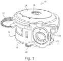
- a blower motor assembly 10 in accordance with an exemplary embodiment generally includes a motor body 12 having a top cover 14 and a bottom cover 16.
- the motor itself is of conventional design and therefore need not be described in detail, other than to note that an output shaft (represented by center axis 48 in Figure 7 ) projects from opposite upper and lower ends of the motor but does not extend through the top and bottom covers 14, 16 of the assembly.
- references herein to terms such as “upper,” “lower,” “top” and “bottom,” etc. are for convenience only as viewed in connection with the drawings, and are not intended to be limiting in any way.
- a gas inlet opening 18 is provided in the top cover 14 and a gas outlet 20 is provided in a side wall of the motor housing 12.
- a power cable 22 extends from the motor body for connection to a power source.
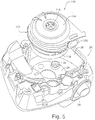
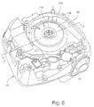
- FIGS 5-7 and 11-14 illustrate a chassis enclosure (or simply, chassis) 24 that is adapted to receive the blower motor assembly 10. More details of the chassis 24 can be found in U.S. Patent Application No. 10/533,840, filed May 4, 2005 .
- the blower motor assembly may be supported on a bottom wall 26 of the chassis 24 via a plurality of coil springs 28 (one shown in Figures 1 , 2 ). Three such springs are employed in the exemplary embodiment but the number and arrangement of such springs may vary. Springs 28 are seated in pockets or recesses 30(see Figures 5 and 14 ) formed in the bottom wall 26 of the chassis 24, with the upper ends of the springs engaged in aligned similar pockets or recesses 31 in the underside of the bottom cover 16 of the blower motor assembly 10 (see Figure 15 ).
- a gas inlet conduit 32 in chassis 24 supplies gas to the blower motor assembly 10, while gas outlet tube 34 connects to the gas outlet opening 20 of the blower motor assembly 10 when the latter is fully seated in the chassis.
- the blower motor assembly 10 is preferably not enclosed within a typical outer motor enclosure or housing.
- the blower motor body 12 ( Figures 1-3 ) itself is able to be installed within a smaller chassis, while maintaining a necessary gap between the motor body 12 and the peripheral side wall 36 of the chassis 24 for establishing the first-to-second stage gas path (as explained in further detail below).
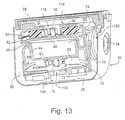
- wall 36 of the chassis 24 may be of double-wall construction ( Figure 7 ) or of single-wall construction ( Figures 11-13 ).
- a chassis lid 38 ( Figures 7 and 11-13 ) is located over the blower motor assembly, closing the upper open end of the chassis.
- blower motor assembly 10 shown in Figures 1-3 is slightly different from the blower motor assembly 110 of Figures 4-7 and 11-14 .
- the assembly shown in Figures 1-3 is shown with various details, some of which are related to manufacturing considerations that may or may not appear in the assembly shown in Figures 4-7 and 11-14 and vice versa, particularly with respect to the blower motor body, top cover and bottom cover.
- the external component of the blower motor assembly in Figures 4-7 and 11-14 are designated by similar reference numbers as used in Figures 1-3 , but with the prefix "1" added.
- assemblies 10 and 110 may be considered different embodiments although they are similar in terms of overall configuration and function.
- the internal components of blower motor assemblies 10 and 110 should be considered substantially identical.
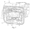
- the blower motor assembly 110 includes a motor body 112 formed with an interior chamber 40 defined by a bottom wall 42 of the body 112, an inner side wall 44 and a motor cap or end bell 46.
- the motor coil and armature (omitted for clarity) are secured within the motor body 112 in conventional fashion and an output shaft, shown schematically at 48, extends in opposite directions through the motor cap 46 and the bottom wall 42 of the body 112.
- the cap 48 and the bottom wall 42 may include suitable bearing supports for the shaft.
- the motor cap 46 engages an upper peripheral edge 52 of the motor body 112 and, via lateral flange 54 and vertical lip 56, engages an internal shoulder 58 of the top cover 114.
- the space 60 (also referred to herein as the "first volute") between the motor cap 46 and the blower motor assembly top cover 114 is occupied by the first stage impeller 62 that is secured to the upper end of the motor output shaft 48 via a center hub or bushing 50.
- the blower motor body 112 is also formed with a depending skirt or outer wall 64 that is connected at its upper end to the inner side wall 44 by a generally horizontal flange 66.
- the flange 66 and thus the upper end of the outer wall 64 spirals downwardly about the inner side wall 44, forming the second stage volute (described further herein)--while the lower end of the outer wall 64 is engaged by the blower motor assembly bottom cover 116 by a telescoping fit indicated at 68.
- the space 70 also referred to herein as the "second volute” between the bottom cover 116 and the bottom wall 42 of the blower motor body 112 is occupied by a second stage impeller 72 that is secured to the lower end of the motor output shaft 48 via a center hub or bushing 75.
- the blower motor body 112 and cap 46 are preferably made of aluminum or other suitable heat conducting material for good thermal conduction, such as magnesium.
- the heat conducting material can help to convectively cool the motor and has good heat transfer characteristics.
- the heat taken away from the motor can be applied to heat the pressurized gas traveling to the patient, e.g., via the air delivery tube. Alternatively, the heat can simply be diverted away from the motor and the air delivery tube.
- the top cover 114 of the blower motor assembly includes upper and lower portions 74, 76, respectively.
- the upper portion may be constructed of a relatively rigid plastic or other suitable lightweight material and has a generally inverted cup-shape, with a center opening or aperture 118 through which air is supplied to the first stage impeller 62.
- the lower portion 76 of the top cover is in the form of a depending skirt, attached to the upper portion 74 adjacent the shoulder or edge 58 by adhesive or any other suitable means.
- the lower portion 76 is preferably constructed of a flexible polymer or rubber material (e.g., silicone rubber) that enables the top cover 114 to seal against the inner peripheral wall 36 of the chassis 24 at 78. The significance of this sealing arrangement will be described further below.
- the gas outlets 20 and 120, respectively, of the blower motor assemblies 10 and 110 are also formed of a flexible material, such as silicone rubber. This results in a flexible sealed connection to the chassis gas outlet tube 34 when the blower motor assemblies 10 or 110 are inserted and properly oriented within the chassis 24.
- the gas outlets 20, 120 each include an outer oval-shaped peripheral rim 82, 182 and an inner, round rim 84, 184 define the outlet openings 86, 186 and that, respectively, are adapted to engage complimentary surfaces on the inner wall of the chassis 24, with rims 84, 184 specifically designed to be sealably engaged by the round outlet tube 34 of the chassis.
- the first and second stage impellers 62, 72 may be identical in design (though must be of mirrored geometry to suit the present embodiment) and, accordingly, only the impeller 62 will be described in detail.
- impeller 62 is of one-piece molded plastic construction, although other suitable materials and manufacturing techniques could be employed.
- the impeller 62 comprises a plurality of continuously curved or straight vanes or blades 88 sandwiched between a pair of disk-like shrouds 90, 92.
- the smaller shroud 92 incorporates the hub or bushing 50 that receives the upper end of the motor shaft 48.
- the shroud 92 overlaps an inner portion of the vanes 88, i.e., the outer diameter (OD) of the smaller shroud is substantially smaller than the OD of the larger shroud 90.
- the latter is formed with a relatively large center opening 94, but this shroud extends to the radially outer tips of the vanes.
- Making the OD of the smaller shroud 92 slightly smaller than the diameter of the center opening 94 in shroud 90 facilitates the molding process used to manufacture the impellers (by allowing the impeller to be easily moulded in one piece).
- both impellers 62, 72 are preferably constructed of a polycarbonate or polypropylene material (the latter of which provides acoustic dampening properties that dampen the resonance of the impellers). Glass fibre reinforcement may be employed to increase the stiffness of the polypropylene or polycarbonate if required.
- each vane may have a profile appropriate for the intended goal and such profile may be tapered.
- each vane may taper in plan view (i.e., the edge thickness of each vane may taper from a larger width to a narrower width from inside to outside), and/or each vane may taper in elevation view (i.e., the height of each vane along the length may taper from a larger height to a smaller height from inside to outside).
- the vane or blade edges adjacent the smaller-diameter shroud may be tapered so that at least the radially outer portion of the blade tapers to a reduced width at the radially outer end of the impeller.
- the cross-section thickness of the vanes may be variable or tapered.
- the tip of the impellers between the edge surface 88.3 which extends beyond the smaller shroud 92 and the transverse tip edges 98 is chamfered or notched to create a transition surface 99 at the tip.
- this transition surface include a straight chamfer 99.1 ( Figures 10-7 ), a convex chamfer, for example arcuate 99.2 ( Figure 10-8 ), or a concave notch 99.3 ( Figures 10-9 ).
- the chamfer or notch dimension is preferably between 0.5-5 mm along each edge (98 and 88.3), more preferably about 2 mm, from the notional corner that is formed by extending the planes of the transverse tip edges 98 and the edge surfaces 88.3 to intersect, as shown in Figure 10-10 .
- the dimension along each edge is not required to be the same.
- the chamfering or notching of the blade as described is intended to further reduce noise, including decreasing the blade passing tones.
- the exterior or outer surfaces of the bottom covers 16, 116 are also provided with a plurality of fixed vanes 100 that may be arranged in three sets of two as shown in Figure 15 , but other arrangements are contemplated as well. These vanes serve, to reduce the degree of swirl or spin of the gas before it flows gas into the second stage impeller 72 as further described herein.
- FIGs 10-1 to 10-6 illustrate an impeller 62.1 according to an alternative design of the present invention.
- impeller 62.1 includes an alternating shroud design, but in addition it is tapered in elevation view, e.g., the height of each vane varies or tapers along its radial length as shown, for example, in Figs. 10-1 and 10-6 .
- Each vane may also be tapered in widthwise direction, as seen in plan view.
- This tapered alternating shroud impeller combines the advantages of an alternating shroud impeller (lower costs, lower inertia and better balance) with the advantages of a tapered impeller (more uniform radial air velocity through the impeller and hence lower noise and higher efficiency).
- the tapered alternating shroud design also provides excellent stiffness and resistance to bending, drooping, or "creep".
- impeller 62.1 has a tapered design and includes a plurality of continuously curved or straight vanes or blades 88.1 sandwiched between a pair of disk-like shrouds 90.1, 92.1.
- Each vane 88.1 includes a first edge 88.2 and a second edge 88.3.
- the radially outer portion 88.4 ( Fig. 10-4 ) of each edge 88.2 abuts or is in contact with or adjacent to an inside surface of shroud 90.1, while the radially inner portion 88.5 ( Fig.
- each edge 88.2 of each vane extends further radially inwardly beyond shroud 90.1 and is visible through opening 90.2 (also referred to as the "small diameter" of shroud 92.1).
- the radially inner portion of each edge 88.3 abuts or is in contact with or adjacent to an inside surface of shroud 92.1, while the radially outer portion of each edge 88.3 of each vane extends further radially outwards beyond shroud 92.1. and is visible in Figure 10-1 .
- the tapered design is created in this example by forming shroud 90.1 in a truncated frusto-conical shape, while shroud 92.1 is generally planar (see Fig. 10-6 ).
- the vanes 88.1 between the shrouds are shaped to fit in the space between the shrouds, such that the vanes gradually taper from the radially inner portion to the radially outer portion of the impeller along the larger-diameter shroud.
- the small and large diameters 90.2, 90.3, respectively, of the truncated cone form a slanted wall 90.4 that is angled relative to shroud 92.1.
- the angle ⁇ is in the range of 0-60°, preferably between 10-30°, depending on the application.
- the shrouds in Figs. 8-10 extend in generally parallel planes, although they may be of varying thickness.
- the smaller shroud 92.1 incorporates the hub or bushing 50.1 that receives the upper end of the motor shaft 48.
- the shroud 92.1 overlaps an inner portion of the vanes 88.1, i.e., the outer diameter (OD) of the smaller shroud 92.1 is substantially smaller than the OD of the larger shroud 90.1.
- Shroud 90.1 is formed with opening 90.2 that does not cover the radially inner portions of the vanes, but shroud 90.1 extends to the radially outer tips of the vanes. Making the OD of the smaller shroud 92.1 slightly smaller than the diameter of the center opening 90.2 in shroud 90.1, facilitates the molding process used to manufacture the impellers.
- impeller 62.1 is preferably constructed of a polycarbonate or polypropylene material which provides acoustic dampening properties (the latter of which dampens the resonance of the impellers). Glass fiber reinforcement may be employed to increase the stiffness of the polypropylene or polycarbonate if required.
- the radially outer portions 96.1 of the vanes or blades 88.1 may taper in width and the transverse tip edges 98.1 may be stepped, similar to what is shown in Figure 10-6 and/or notched or chamfered 99 as shown in figures 10-7 to 10-10 and described above.
- vane features are intended to reduce noise, and stepped edges specifically function to break up pressure pulses around the tips of the vanes.
- the trailing edges of the impeller blades may be disrupted by other disturbances, such as but not limited to dimpling or roughening. Such disturbances break up the smooth flow of air trailing off the blade edges and assist in reducing noise.
- Impeller 62.1 is also strong (higher rpms possible) and is even lower inertia (faster response) and possibly quieter than impeller 62, which is a generally parallel arrangement. Further, impeller 62.1 can be made in one piece due to its design.
- the tapered alternating shroud embodiment is low cost and has good balance, very low inertia, low noise, and high strength.
- the use of a tapered, shrouded design also involves less material usage.
- the tapered design can also result in more even gas velocity, e.g., velocity is kept constant between the radially inner and outer ends of the vanes.
- the gap between the top of the impeller and the top cover of a double shrouded impeller is not as sensitive to tolerances, compared to a single shroud impeller.
- the top gap is very sensitive to variation, as the air can spill over the top of the blade if the top cover is relatively far away.
- the first volute is defined by the space 60 (enclosing the first stage impeller 62 and also including an annular volute region immediately outward of the impeller) which is formed by the underside of the top cover 114 and the upper (or outer) side of the motor cap 46.
- the air follows an inter-stage (i.e., a stage-to-stage) path 102 which is a radially outer, downward spiral path in the area between the outer peripheral skirt 64 of the blower motor body 112 and the inner wall 36 of the chassis 24 leading to an inlet opening 104 in the blower motor body bottom cover 116.
- This inlet opening feeds the air pressurized by the first impeller 62 within the first volute 60 and transferred to the second stage impeller 72 and the second volute 70 via the inter-stage (stage-to-stage) path 102, with the gas flow into the opening 104 smoothed (deswirled) by vanes 100.
- the second volute is defined by the chamber or space 70 enclosing the second stage impeller 72 and continuing in an upward spiral path between the outer and inner walls 64, 44, respectively, of the motor housing, leading to the gas outlet 20, 120.
- the first and second volutes may have similar or different shapes. However, the first volute can be said to "ramp down", while the second volute can be said to "ramp up”.
- Each ramp profile is preferably smooth, but each can also have a stepped gradient as well.
- gas typically air or oxygen
- conduit 32 and hole 33 gas is supplied to the blower motor assembly 110 via conduit 32 and hole 33.
- the air is then drawn in through inlet opening 118 and into the first stage impeller 62.
- the impeller spins the gas and, in combination with the first volute 60 pressurizes the gas. After decelerating as it leaves the first volute, it flows in a downward spiral on the inter-stage (stage-to-stage) path 102, moving into the space between the motor body 112 and the chassis wall 36.
- the seal at 78 between the motor body top cover 114 and the chassis wall 36 prevents pressurized gas from escaping back into the nonpressurized area above the inlet opening 118.
- the flexible nature of the seal also contributes to the vibration isolation of the blower motor assembly relative to the chassis enclosure.
- blower described herein can be used for use in CPAP, NIPPV and BiLevel treatment of OSA, it should noted that the blower could also easily be used or adapted for use with invasive ventilation as well.
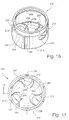
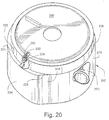
- a blower motor assembly 200 ( Figures 20 , 21 ), similar to the assemblies described hereinabove, is substantially enclosed by a cup-shaped, flexible sleeve 202, best seen in Figures 16-19 .
- the sleeve 202 includes a peripheral side wall 204 and a bottom wall 206.
- the bottom wall 206 of the sleeve may be formed with internal curved vanes 208 that surround the second stage inlet opening of the blower motor assembly in a manner similar to the arrangement of vanes 100 described above.
- the vanes 208 are preferably formed integrally with the bottom wall 206, but could be separately applied, if desired, by for example, a suitable adhesive.
- the vanes could also be formed on the underside of the blower motor assembly bottom cover as in the previously described embodiments.
- a plurality of support feet 210 are shown integrally molded within circular recesses 212 formed in the bottom wall 232.
- Another support arrangement could be one large cylindrical web 211 on the bottom outer face 233 of the sleeve, as shown in Figure 22 .
- the peripheral side wall 204 of the sleeve 202 is substantially circular in cross-section, but with a pair of "flats" 214, 216 on either side of an aperture 218 adapted to receive the gas outlet connector boss 220 (see Figure 20 ).
- the upper end of the sleeve may be formed with a reduced diameter portion defining an upper rim 222 connected to the adjacent remaining sleeve portion by a radial shoulder 224. Note that the rim 222 merges with the main portion of the sidewall 204 at the flats 214, 216 such that the shoulder 224 terminates at locations 226, 228. Rim 222 terminates at an internal, circular flange or lip 230 located radially inwardly of the rim 222. It will be appreciated that other equivalent attaching and/or sealing arrangements at the open end of the sleeve are within the scope of this invention.
- the rim 222 of the sleeve engages the peripheral rim of the top cover 232 in a snug, elastic fashion, with lip 230 seated in a circular groove 234 in the cover.
- This elastic engagement provides a sufficient seal to prevent escape of air/gas from the space between the motor body and the sleeve.
- Figure 21 illustrates the blower motor assembly located within a chassis enclosure 238. It will be appreciated that when pressurized gas/air flows between the stage 1 and stage 2 volutes radially between the blower motor assembly 200 and the flexible sleeve 202), the flexible sleeve may be expanded radially outwardly into at least partial engagement with an interior wall 240 of the chassis enclosure 238. In this condition, vibrations will still be isolated by the air cushion inside the sleeve. In other words, the pressurized inter-stage gas/air thereby at least partially supports the blower motor assembly in a manner that isolates vibration while it also cushions the motor from damage during rough handling, transport, etc. In this regard, the resilient and flexible support feet 210 replace the springs 28, thus eliminating discrete components that can be difficult to handle and assemble.
- a hole 236 in the shoulder 224 ( Figure 17 ) is utilized for wires connected to the blower motor within the motor body.
- a notch could be provided in the upper lip or rim 222, opposite the aperture 218.
- the flexible sleeve 202 may be made of any suitable flexible material, such as rubber, silicone, silicone rubber or a thermoplastic elastomer (TPE).
- suitable flexible material such as rubber, silicone, silicone rubber or a thermoplastic elastomer (TPE).
- incorporación of a flexible sleeve permits the size of the blower motor assembly to be reduced since the interstage air/gas now performs two functions in one space, i.e., the flowpath between stages and a vibration isolating and bump cushioning element.
- the device may be made quieter since more space is made available to the inlet muffler volume.
- a further advantage is the elimination of the flexible seal portion 76 of the top cover as described hereinabove.
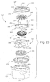
- Figure 23 is an exploded view of another alternative embodiment of a blower motor assembly 242 including a first stage impeller 244 associated with a first volute component (also referred to herein as a motor cap or end bell) 246 and a second stage impeller 248 associated with a second volute component (also referred to as the motor body) 250,
- the blower motor assembly is axially stackable so capable of automatic assembly. Additionally, the volute components are axially compact, and sandwiched between upper and lower lids as described below.
- the first and second volute components 246, 250 are coupled together with the motor M therebetween.
- the first volute component 246 may include a plurality of holes 252 to receive threaded screws 254 for fastening the first volute component to the second volute component provided with aligned threaded holes for receiving the screws 254.
- the second volute component 250 can be adhesively coupled to the first volute component 246, or the first volute component can be press fit onto the second volute component.
- a rotor 256 of the motor is positioned within between volute components 246 and 250, and the rotor includes a first shaft end 258 coupled to the first impeller 244 and a second axially aligned shaft end 260 coupled to the second stage impeller 258.
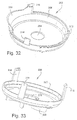
- a top lid or cover 262 includes an inlet 264 and is positioned over the first impeller, and a bottom lid or cover 266 is positioned under and adjacent the second stage impeller 248.
- the bottom lid includes a plurality of vanes 268 surrounding an inlet 270.
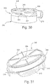
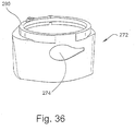
- a flexible motor sleeve 272 ( Figures 23 , 24 , 35 and 36 ) surrounds substantially the entire assembly, but includes a cut out portion 274 to receive the outlet 276 of the second volute component 250.
- the sleeve 272 is an elastomeric component that dampens vibration and/or resonance of internal components. The use of the sleeve 272 may result in fewer parts as compared to common motor assemblies.
- the sleeve 272 may be insert-molded onto aluminium, or it may co-molded onto the top and/or bottom lids.
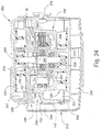
- FIG 24 shows additional details of the motor M and its positional relationship to the first and second volutes.
- the motor M includes a laminated stack 278, a plurality of windings 280 and rotor magnet 282.
- the motor shaft 284 (which includes shaft ends 258, 260) is supported by upper and lower bearings 286, 288.
- the volute components 246, 250 are at least partially nested, which provides for a compact and space saving design, particularly in the axial direction, while the sleeve 272 also helps conserve space in a radial direction.
- the sleeve 272 is sealingly coupled to the motor assembly, e.g., using a thickened portion 290 of silicone around its upper surface, as shown in Figures 24 and 33 , stretched about the edge of the upper lid or cover 262.
- Figure 25 shows the first volute component 246 with a part annular ramp surface 292 defining a flow channel 294 extending approximately 180° with increasing depth from an "inlet" end of the channel at 296 to an “outlet” end 298.
- Figures 26-30 illustrate the first and second volute components 246, 250 in combination, without the motor.
- These figures illustrate the inter-stage path of a gas (for example, air) as it is channelled from the first impeller 244 to the second impeller 248, and hence from the first volute 247 to the second volute 251.
- This inter-stage path is generally concentric relative to the motor shaft 284 and defines a transition zone designed to ramp downwardly in a spiral fashion from the first volute to the second volute.
- first two arrows in Figure 26 lie on surface 292 of channel 294 in the first volute, and the third arrow lies on a more steeply-inclined ramp surface on the outside of the second volute component 250, which, in turn, continues along a substantially horizontal surface 302, also on the second volute component 250.
- a groove 304 is now formed between surface 302 and the underside of the first volute component 246.
- This groove is tapered in the circumferential direction, with surface 302 rising slightly toward the first volute component 246 as best seen in Figures 28-30 so as to encourage forward and continued movement gas remaining in the first volute 246 and any decelerated gas in the inter-stage path, about the second volute component 250.
- a notch 255 in an inner wall 257 of the second volute component 250 permits passage of the motor wires (not shown).
- the gas spirals downwardly through the transitional zone and enters into the area 306 which also extends below the bottom lid or cover 266 and then into the opening 270 and into the second volute 251.
- Vanes 268 reduce the degree of swirl or spin as the gas flows to the second volute where the gas is then swirled about the volute 251 via second impeller 248 and upwardly to the outlet 276.
- the top lid or cover 262 includes a flat upper surface 307 provided with the inlet opening 264 and a peripheral depending skirt 308.
- An outlet hood 310 depends from a portion of the skirt 308 and covers the transition zone between the first and second volutes, allowing the gas to move radially outwards to fill the stage-to-stage or inter-stage path.
- Attachment tabs 312, 314 and 316 serve to attach the upper lid to the underside of the first volute component 246.
- the bottom lid 266 is also formed with upstanding attachment tabs 314, 316, 318 on skirt 320 adapted to engage a peripheral rim 322 on the second volute component 250.
- the flexible sleeve 272 is telescopically received over the motor/volute assembly so as to further define the inter-stage gas path, as described above in connection with the embodiment illustrated in Figure 21 , and the manner in which the sleeved blower motor assembly described in connection with Figures 23-36 operates is otherwise similar to the embodiment shown in Figures 16-21 .
- each of the blades may be tapered towards the outside of the impeller, e.g., to axially move the blade tips from the cut-off to decrease the blade pass tone.
- This structure may also maintain the cross-sectional area as moving out from the center of the impeller closer to constant. This will encourage the airflow to maintain contact with the blades, to increase efficiency and/or decrease noise.
- the surfaces of the components adjacent the impellers could be tapered to match the impeller shapes, thereby providing a constant distance between those surfaces and the impeller blade edges.
- the impellers 244, 248 also have an alternating shroud design as described above which can also help reduce noise.
- the motor assembly thus described has a low inertia which may allow for use in other applications, e.g., to respond quickly for other therapies and/or to increase response of transducer(s).
- the temperature of the motor is cooler, and drag from the bearing heat is less due to running the slower speeds of the motor, which helps with reliability.
- the integrated volutes can help conduct heat into the air path to warm the air, which also has the effect of improving the reliability of the motor. Further, the generated heat can warm the air path, which can be advantageous in cooler conditions. Another benefit is that there is less pressure across the bearings as a result of multistage air path.
- a mode of operation may be provided where the flow through the motor is intentionally oscillated to be faster than the breathing rate.
- the results can be useful for diagnostic purposes, e.g., to determine open or closed airway or for other diagnostic purposes.
- Suitable oscillation techniques are described in commonly owned U.S. Patent No. 5,704,345 . Such information can also be used to activate an active vent.
- a thermal cutout may be provided on the motor. The cutout would monitor the heat in the motor casing, and shut off power in the event of an overheat.
- the impellers could be structured to spin in either the same directions or in opposite directions.
- the blower assembly could include a port for water egress, such as holes at the bottom of the sleeve, to protect against water pooling at the bottom of the motor if it spills back from an attached humidifier.
- motor housing body and the first and second volute components may be integrated.
- each end of the motor shaft may include multiple impellers.
- the various embodiments described above may be implemented in conjunction with other embodiments, e.g., aspects of one embodiment may be combined with aspects of another embodiment to realize yet other embodiments. Further, each component or feature alone for any given embodiment may constitute an independent embodiment.
- the invention has particular application to patients who suffer from OSA, it is to be appreciated that patients who suffer from other illnesses (e.g., congestive heart failure, diabetes, morbid obesity, stroke, barriatric surgery, etc.) can derive benefit from the above teachings.
- the above teachings have applicability with patients and non-patients alike in non-medical applications.
Landscapes
- Engineering & Computer Science (AREA)
- Health & Medical Sciences (AREA)
- General Engineering & Computer Science (AREA)
- Mechanical Engineering (AREA)
- Life Sciences & Earth Sciences (AREA)
- Biomedical Technology (AREA)
- Heart & Thoracic Surgery (AREA)
- Hematology (AREA)
- Anesthesiology (AREA)
- Animal Behavior & Ethology (AREA)
- General Health & Medical Sciences (AREA)
- Public Health (AREA)
- Veterinary Medicine (AREA)
- Pulmonology (AREA)
- Emergency Medicine (AREA)
- Structures Of Non-Positive Displacement Pumps (AREA)
Claims (14)
- Positive Atemwegsdruckvorrichtung zum Zuführen von druckbeaufschlagtem Therapiegas, die aufweist:ein Gebläse (10, 110, 242), um Gas mit Druck im Bereich von etwa 4-30 cmH2O zu beaufschlagen;wobei jedes Gebläse einen Motor mit einer Welle (48, 284) und einem Laufrad (62, 72, 62.1, 244, 248) hat und das Laufrad aufweist:einen oberen Kragen (92, 92.1),einen ebenen unteren Kragen (90, 90.1),mehrere Flügel (88, 88.1), die sich vom oberen Kragen zum unteren Kragen erstrecken, wobei jeder Flügel eine Oberkante an einem Radialinnenabschnitt des Flügels in Kontakt mit dem oberen Kragen und eine Unterkante an einem Radialaußenabschnitt des Flügels in Kontakt mit dem unteren Kragen aufweist, so dass ein Radialinnenabschnitt des Flügels an der Unterkante jedes Flügels nicht in Kontakt mit dem unteren Kragen steht und ein Radialaußenabschnitt des Flügels an der Oberkante jedes Flügels nicht in Kontakt mit dem oberen Kragen steht.
- Positive Atemwegsdruckvorrichtung nach Anspruch 1, wobei jeder Flügel eine Breite hat, die vom Radialinnenabschnitt zum Radialaußenabschnitt konstant ist.
- Positive Atemwegsdruckvorrichtung nach Anspruch 1, wobei jeder Flügel eine Kantendicke und/oder -höhe hat, die vom Radialinnenabschnitt zum Radialaußenabschnitt variiert.
- Positive Atemwegsdruckvorrichtung nach Anspruch 3, wobei sich die Kantendicke und/oder -höhe vom Radialinnenabschnitt zum Radialaußenabschnitt verjüngt.
- Positive Atemwegsdruckvorrichtung nach einem der Ansprüche 1 oder 3-4, wobei der obere Kragen eine Kegelstumpfform mit einer Oberfläche hat, die relativ zum unteren Kragen im Bereich von 15-25 Grad abgewinkelt ist.
- Positive Atemwegsdruckvorrichtung nach einem der Ansprüche 1-2, wobei sich der obere Kragen in einer Ebene erstreckt, die parallel zu einer Ebene ist, in der der untere Kragen enthalten ist.
- Positive Atemwegsdruckvorrichtung nach einem der Ansprüche 1-6, wobei ein Durchmesser des unteren Kragens größer als ein Durchmesser des oberen Kragens ist.
- Positive Atemwegsdruckvorrichtung nach einem der Ansprüche 1-7, wobei ein Durchmesser des unteren Kragens größer als ein maximales Radialausmaß der Flügel ist.
- Positive Atemwegsdruckvorrichtung nach einem der Ansprüche 1-8, wobei jeder Flügel eine abgestufte Querkante an seinem radial äußersten Ende hat.
- Positive Atemwegsdruckvorrichtung nach einem der Ansprüche 1-9, wobei jedes Laufrad aus Polycarbonatmaterial und/oder Polypropylenmaterial aufgebaut ist.
- Positive Atemwegsdruckvorrichtung nach einem der Ansprüche 1-10, wobei jedes Laufrad mit Oberflächenstörungen entlang von Hinterkanten davon ausgebildet ist.
- Positive Atemwegsdruckvorrichtung nach einem der Ansprüche 1-11, wobei der obere Kragen eine Nabe oder Buchse aufweist, um ein oberes Ende einer Motorwelle aufzunehmen.
- Positive Atemwegsdruckvorrichtung nach einem der Ansprüche 1-12, wobei die Welle zwei Enden hat und an jedem Ende mindestens ein solches Laufrad vorgesehen ist.
- Positive Atemwegsdruckvorrichtung nach einem der Ansprüche 1-13, wobei die Vorrichtung eingerichtet ist, Wärme vom Motor dem Druckgas zuzuführen.
Priority Applications (1)
| Application Number | Priority Date | Filing Date | Title |
|---|---|---|---|
| EP18209788.1A EP3492132B1 (de) | 2005-10-28 | 2006-10-27 | Ein- oder mehrstufengebläse und verschachtelte(s) spiralgehäuse und/oder impeller dafür |
Applications Claiming Priority (5)
| Application Number | Priority Date | Filing Date | Title |
|---|---|---|---|
| US73087505P | 2005-10-28 | 2005-10-28 | |
| US77533306P | 2006-02-22 | 2006-02-22 | |
| US84120206P | 2006-08-31 | 2006-08-31 | |
| PCT/AU2006/001617 WO2007048206A1 (en) | 2005-10-28 | 2006-10-27 | Single or multiple stage blower and nested volute(s) and/or impeller(s) therefor |
| EP06804445.2A EP1940496B1 (de) | 2005-10-28 | 2006-10-27 | Ein- oder mehrstufiges gebläse und verschachtelte diffusor und/oder laufräder dafür |
Related Parent Applications (1)
| Application Number | Title | Priority Date | Filing Date |
|---|---|---|---|
| EP06804445.2A Division EP1940496B1 (de) | 2005-10-28 | 2006-10-27 | Ein- oder mehrstufiges gebläse und verschachtelte diffusor und/oder laufräder dafür |
Related Child Applications (1)
| Application Number | Title | Priority Date | Filing Date |
|---|---|---|---|
| EP18209788.1A Division EP3492132B1 (de) | 2005-10-28 | 2006-10-27 | Ein- oder mehrstufengebläse und verschachtelte(s) spiralgehäuse und/oder impeller dafür |
Publications (2)
| Publication Number | Publication Date |
|---|---|
| EP3045196A1 EP3045196A1 (de) | 2016-07-20 |
| EP3045196B1 true EP3045196B1 (de) | 2018-12-12 |
Family
ID=37967357
Family Applications (4)
| Application Number | Title | Priority Date | Filing Date |
|---|---|---|---|
| EP16153742.8A Not-in-force EP3045196B1 (de) | 2005-10-28 | 2006-10-27 | Ein- oder mehrstufengebläse und verschachtelte(s) spiralgehäuse und/oder impeller dafür |
| EP06804445.2A Active EP1940496B1 (de) | 2005-10-28 | 2006-10-27 | Ein- oder mehrstufiges gebläse und verschachtelte diffusor und/oder laufräder dafür |
| EP18209788.1A Active EP3492132B1 (de) | 2005-10-28 | 2006-10-27 | Ein- oder mehrstufengebläse und verschachtelte(s) spiralgehäuse und/oder impeller dafür |
| EP06804444.5A Active EP1940495B1 (de) | 2005-10-28 | 2006-10-27 | Gebläsemotor mit flexibler stützhülse |
Family Applications After (3)
| Application Number | Title | Priority Date | Filing Date |
|---|---|---|---|
| EP06804445.2A Active EP1940496B1 (de) | 2005-10-28 | 2006-10-27 | Ein- oder mehrstufiges gebläse und verschachtelte diffusor und/oder laufräder dafür |
| EP18209788.1A Active EP3492132B1 (de) | 2005-10-28 | 2006-10-27 | Ein- oder mehrstufengebläse und verschachtelte(s) spiralgehäuse und/oder impeller dafür |
| EP06804444.5A Active EP1940495B1 (de) | 2005-10-28 | 2006-10-27 | Gebläsemotor mit flexibler stützhülse |
Country Status (7)
| Country | Link |
|---|---|
| US (10) | US8272837B2 (de) |
| EP (4) | EP3045196B1 (de) |
| JP (4) | JP5096351B2 (de) |
| CN (1) | CN103185027B (de) |
| AU (14) | AU2006308435B2 (de) |
| NZ (4) | NZ567376A (de) |
| WO (2) | WO2007048206A1 (de) |
Families Citing this family (190)
| Publication number | Priority date | Publication date | Assignee | Title |
|---|---|---|---|---|
| US8517012B2 (en) * | 2001-12-10 | 2013-08-27 | Resmed Limited | Multiple stage blowers and volutes therefor |
| US6910483B2 (en) * | 2001-12-10 | 2005-06-28 | Resmed Limited | Double-ended blower and volutes therefor |
| CN1859940B (zh) | 2003-09-25 | 2010-06-16 | 雷斯梅德有限公司 | 呼吸机面罩及其系统 |
| DE102005031388B4 (de) | 2005-07-05 | 2017-05-04 | Resmed Limited | Vorrichtung zur Förderung eines Atemgases |
| EP3045196B1 (de) | 2005-10-28 | 2018-12-12 | ResMed Motor Technologies Inc | Ein- oder mehrstufengebläse und verschachtelte(s) spiralgehäuse und/oder impeller dafür |
| USD577807S1 (en) | 2006-10-27 | 2008-09-30 | Resmed Limited | Impeller |
| EP2032857B1 (de) | 2006-05-24 | 2011-02-23 | ResMed Motor Technologies Inc. | Kompaktes, geräuscharmes effizientes gebläse für cpap-geräte |
| EP2063945B1 (de) | 2006-09-07 | 2019-07-03 | ResMed Ltd. | Maske und flussgeneratorsystem |
| US8638014B2 (en) | 2006-10-24 | 2014-01-28 | Resmed Motor Technologies Inc | Brushless DC motor with bearings |
| USD642676S1 (en) | 2006-10-27 | 2011-08-02 | Resmed Motor Technologies Inc | Flexible motor sleeve |
| US20080187437A1 (en) * | 2007-02-07 | 2008-08-07 | Apex Medical Corp. | Air blower having a raised column therein to reduce air flow pressure change and noise |
| US8720728B2 (en) | 2007-03-09 | 2014-05-13 | Simplehuman, Llc | Trash can |
| AU2008202487B2 (en) | 2007-06-05 | 2013-07-04 | Resmed Motor Technologies Inc. | Blower with Bearing Tube |
| GB0814835D0 (en) | 2007-09-04 | 2008-09-17 | Dyson Technology Ltd | A Fan |
| WO2009058032A1 (en) * | 2007-10-30 | 2009-05-07 | Fisher & Paykel Healthcare Limited | Fan unit with bypass vent holes |
| NZ593449A (en) | 2008-01-31 | 2012-12-21 | Resmed Ltd | Respiratory apparatus with a pair of delivery conduits |
| AU2014200366B2 (en) * | 2008-01-31 | 2014-12-11 | ResMed Pty Ltd | Respiratory Apparatus |
| US10350379B2 (en) | 2008-06-05 | 2019-07-16 | ResMed Pty Ltd | Treatment of respiratory conditions |
| GB2464736A (en) | 2008-10-25 | 2010-04-28 | Dyson Technology Ltd | Fan with a filter |
| US8453640B2 (en) | 2008-11-12 | 2013-06-04 | Resmed Limited | Positive airway pressure device |
| GB2468320C (en) * | 2009-03-04 | 2011-06-01 | Dyson Technology Ltd | Tilting fan |
| GB0903682D0 (en) | 2009-03-04 | 2009-04-15 | Dyson Technology Ltd | A fan |
| GB2468312A (en) | 2009-03-04 | 2010-09-08 | Dyson Technology Ltd | Fan assembly |
| RU2526135C2 (ru) | 2009-03-04 | 2014-08-20 | Дайсон Текнолоджи Лимитед | Вентилятор |
| GB2468331B (en) | 2009-03-04 | 2011-02-16 | Dyson Technology Ltd | A fan |
| GB2476172B (en) | 2009-03-04 | 2011-11-16 | Dyson Technology Ltd | Tilting fan stand |
| WO2010100462A1 (en) | 2009-03-04 | 2010-09-10 | Dyson Technology Limited | Humidifying apparatus |
| WO2010126383A1 (en) | 2009-04-29 | 2010-11-04 | Fisher & Paykel Healthcare Limited | A fan unit with improved surge characteristics |
| AU2015201791B2 (en) * | 2009-04-29 | 2017-03-09 | Fisher & Paykel Healthcare Limited | A Fan Unit with Improved Surge Characteristics |
| US10238822B2 (en) | 2009-05-29 | 2019-03-26 | Resmed Limited | PAP system |
| US8931481B2 (en) | 2009-06-04 | 2015-01-13 | Redmed Limited | Flow generator chassis assembly with suspension seal |
| ATE537865T1 (de) * | 2009-07-06 | 2012-01-15 | Pari Gmbh | Kompressor einer aerosoltherapievorrichtung |
| EP4059553A1 (de) | 2009-08-11 | 2022-09-21 | ResMed Motor Technologies Inc. | Modulares ventilatorsystem |
| FR2949517B1 (fr) * | 2009-08-25 | 2011-10-21 | Snecma | Carter de turbomachine a etancheite renforcee |
| NZ613721A (en) | 2009-08-28 | 2015-02-27 | Resmed Ltd | Pap system |
| EP2317150B1 (de) * | 2009-10-29 | 2019-12-18 | ResMed Pty Ltd | Patientenbeatmungsvorrichtung und Komponenten davon |
| WO2011054038A1 (en) | 2009-11-03 | 2011-05-12 | Resmed Ltd | Cpap systems |
| GB0919473D0 (en) | 2009-11-06 | 2009-12-23 | Dyson Technology Ltd | A fan |
| TW201116723A (en) * | 2009-11-11 | 2011-05-16 | Xiu-Ying Chen | Method for manufacturing air blower housing |
| CN111664101B (zh) | 2009-11-19 | 2022-03-15 | 瑞思迈发动机及马达技术股份有限公司 | 鼓风机 |
| US9434538B2 (en) | 2010-03-12 | 2016-09-06 | Simplehuman, Llc | Trash can |
| GB2478927B (en) | 2010-03-23 | 2016-09-14 | Dyson Technology Ltd | Portable fan with filter unit |
| MY152313A (en) | 2010-05-27 | 2014-09-08 | Dyson Technology Ltd | Device for blowing air by means of a nozzle assembly |
| GB2482547A (en) | 2010-08-06 | 2012-02-08 | Dyson Technology Ltd | A fan assembly with a heater |
| GB2483448B (en) | 2010-09-07 | 2015-12-02 | Dyson Technology Ltd | A fan |
| DE102010046870B4 (de) * | 2010-09-29 | 2016-09-22 | Pierburg Gmbh | Seitenkanalgebläse, insbesondere Sekundärluftgebläse für eine Verbrennungskraftmaschine |
| WO2012049470A1 (en) | 2010-10-13 | 2012-04-19 | Dyson Technology Limited | A fan assembly |
| GB2484670B (en) | 2010-10-18 | 2018-04-25 | Dyson Technology Ltd | A fan assembly |
| WO2012052735A1 (en) | 2010-10-18 | 2012-04-26 | Dyson Technology Limited | A fan assembly |
| JP5778293B2 (ja) | 2010-11-02 | 2015-09-16 | ダイソン テクノロジー リミテッド | 送風機アセンブリ |
| GB2486019B (en) | 2010-12-02 | 2013-02-20 | Dyson Technology Ltd | A fan |
| EP3747489B1 (de) | 2011-02-25 | 2024-03-27 | ResMed Motor Technologies Inc | Gebläse und pap-system |
| US9849258B2 (en) * | 2011-04-05 | 2017-12-26 | Resmed Limited | Respiratory breathing apparatus |
| WO2012145358A2 (en) | 2011-04-18 | 2012-10-26 | Resmed Motor Technologies Inc | Pap system blower |
| US10137264B2 (en) | 2011-07-13 | 2018-11-27 | Fisher & Paykel Healthcare Limited | Respiratory assistance apparatus |
| EP2731656B1 (de) * | 2011-07-13 | 2017-03-22 | Fisher & Paykel Healthcare Limited | Laufrad und motoranordnung |
| GB2493506B (en) | 2011-07-27 | 2013-09-11 | Dyson Technology Ltd | A fan assembly |
| WO2013014419A2 (en) | 2011-07-27 | 2013-01-31 | Dyson Technology Limited | A fan assembly |
| EP2739857B1 (de) | 2011-08-05 | 2017-04-26 | ResMed Motor Technologies Inc. | Gebläse |
| US10279996B2 (en) * | 2011-09-16 | 2019-05-07 | Simplehuman, Llc | Receptacle with low friction and low noise motion damper for lid |
| GB201119500D0 (en) | 2011-11-11 | 2011-12-21 | Dyson Technology Ltd | A fan assembly |
| GB2496877B (en) | 2011-11-24 | 2014-05-07 | Dyson Technology Ltd | A fan assembly |
| GB2498547B (en) | 2012-01-19 | 2015-02-18 | Dyson Technology Ltd | A fan |
| GB2499042A (en) | 2012-02-06 | 2013-08-07 | Dyson Technology Ltd | A nozzle for a fan assembly |
| GB2499044B (en) | 2012-02-06 | 2014-03-19 | Dyson Technology Ltd | A fan |
| GB2499041A (en) | 2012-02-06 | 2013-08-07 | Dyson Technology Ltd | Bladeless fan including an ionizer |
| GB2500011B (en) | 2012-03-06 | 2016-07-06 | Dyson Technology Ltd | A Humidifying Apparatus |
| GB2500005B (en) | 2012-03-06 | 2014-08-27 | Dyson Technology Ltd | A method of generating a humid air flow |
| GB2500010B (en) | 2012-03-06 | 2016-08-24 | Dyson Technology Ltd | A humidifying apparatus |
| RU2606194C2 (ru) | 2012-03-06 | 2017-01-10 | Дайсон Текнолоджи Лимитед | Узел вентилятора |
| GB2500017B (en) | 2012-03-06 | 2015-07-29 | Dyson Technology Ltd | A Humidifying Apparatus |
| GB2500012B (en) | 2012-03-06 | 2016-07-06 | Dyson Technology Ltd | A Humidifying Apparatus |
| CA2808725C (en) | 2012-03-09 | 2020-03-24 | Simplehuman, Llc | Trash cans with features to aid in actuation |
| US9790025B2 (en) | 2012-03-09 | 2017-10-17 | Simplehuman, Llc | Trash can with clutch mechanism |
| GB2500903B (en) | 2012-04-04 | 2015-06-24 | Dyson Technology Ltd | Heating apparatus |
| GB2501301B (en) | 2012-04-19 | 2016-02-03 | Dyson Technology Ltd | A fan assembly |
| GB2532557B (en) | 2012-05-16 | 2017-01-11 | Dyson Technology Ltd | A fan comprsing means for suppressing noise |
| RU2636974C2 (ru) | 2012-05-16 | 2017-11-29 | Дайсон Текнолоджи Лимитед | Вентилятор |
| GB2518935B (en) | 2012-05-16 | 2016-01-27 | Dyson Technology Ltd | A fan |
| USD721338S1 (en) * | 2012-06-10 | 2015-01-20 | Apple Inc. | Thermal device |
| GB2503907B (en) | 2012-07-11 | 2014-05-28 | Dyson Technology Ltd | A fan assembly |
| US9127763B2 (en) * | 2012-08-06 | 2015-09-08 | Asi Technologies, Inc. | Motor housing with integrated gears |
| CN102937101B (zh) * | 2012-11-21 | 2015-05-06 | 王卫 | 一种自增压低压大流量气泵 |
| US10471225B2 (en) * | 2012-12-18 | 2019-11-12 | Fisher & Paykel Healthcare Limited | Impeller and motor assembly |
| AU2015218543B2 (en) * | 2012-12-18 | 2017-09-07 | Fisher & Paykel Healthcare Limited | Impeller and motor assembly |
| BR302013003358S1 (pt) | 2013-01-18 | 2014-11-25 | Dyson Technology Ltd | Configuração aplicada em umidificador |
| AU350179S (en) | 2013-01-18 | 2013-08-15 | Dyson Technology Ltd | Humidifier or fan |
| AU350140S (en) | 2013-01-18 | 2013-08-13 | Dyson Technology Ltd | Humidifier or fan |
| AU350181S (en) | 2013-01-18 | 2013-08-15 | Dyson Technology Ltd | Humidifier or fan |
| GB2510195B (en) | 2013-01-29 | 2016-04-27 | Dyson Technology Ltd | A fan assembly |
| KR101762665B1 (ko) | 2013-01-29 | 2017-07-28 | 다이슨 테크놀러지 리미티드 | 팬 어셈블리 |
| US9051093B2 (en) | 2013-03-01 | 2015-06-09 | Simplehuman, Llc | Receptacle with motion damper near lid |
| CA152657S (en) | 2013-03-07 | 2014-05-20 | Dyson Technology Ltd | Fan |
| CA152655S (en) | 2013-03-07 | 2014-05-20 | Dyson Technology Ltd | Fan |
| CA152656S (en) | 2013-03-07 | 2014-05-20 | Dyson Technology Ltd | Fan |
| USD729372S1 (en) | 2013-03-07 | 2015-05-12 | Dyson Technology Limited | Fan |
| CA152658S (en) | 2013-03-07 | 2014-05-20 | Dyson Technology Ltd | Fan |
| BR302013004394S1 (pt) | 2013-03-07 | 2014-12-02 | Dyson Technology Ltd | Configuração aplicada a ventilador |
| USD736905S1 (en) * | 2013-03-08 | 2015-08-18 | Covidien Lp | Exhalation module EVQ housing |
| USD736289S1 (en) * | 2013-03-11 | 2015-08-11 | Asi Technologies, Inc. | Integrated motor assembly |
| JP2015010695A (ja) * | 2013-07-02 | 2015-01-19 | 日本精工株式会社 | 転がり軸受 |
| GB2530906B (en) | 2013-07-09 | 2017-05-10 | Dyson Technology Ltd | A fan assembly |
| TWD172707S (zh) | 2013-08-01 | 2015-12-21 | 戴森科技有限公司 | 風扇 |
| CA154722S (en) | 2013-08-01 | 2015-02-16 | Dyson Technology Ltd | Fan |
| CA154723S (en) | 2013-08-01 | 2015-02-16 | Dyson Technology Ltd | Fan |
| GB2518638B (en) | 2013-09-26 | 2016-10-12 | Dyson Technology Ltd | Humidifying apparatus |
| DE102013016600B4 (de) * | 2013-10-07 | 2019-03-21 | Dräger Safety AG & Co. KGaA | Gebläsefiltergerät, Atemschutzsystem und Verfahren |
| FR3014320B1 (fr) * | 2013-12-10 | 2017-08-25 | Air Liquide Medical Systems | Appareil d’assistance respiratoire a turbine motorisee et butees |
| CA3160568A1 (en) | 2013-12-23 | 2015-07-02 | Fisher & Paykel Healthcare Limited | Blower for breathing apparatus |
| CN107120318A (zh) * | 2014-01-03 | 2017-09-01 | 北京怡和嘉业医疗科技股份有限公司 | 风机装置和包括这种风机装置的呼吸机 |
| US9651054B2 (en) * | 2014-02-11 | 2017-05-16 | Asia Vital Components Co., Ltd. | Series fan frame body structure made of different materials |
| USD743556S1 (en) * | 2014-02-19 | 2015-11-17 | Resmed Limited | Positive airway pressure delivery console |
| USD730008S1 (en) | 2014-03-12 | 2015-05-19 | Simplehuman, Llc | Trash can |
| US9751692B2 (en) | 2014-03-14 | 2017-09-05 | Simplehuman, Llc | Dual sensing receptacles |
| US10279997B2 (en) | 2014-03-14 | 2019-05-07 | Simplehuman, Llc | Trash can assembly |
| US9856080B2 (en) | 2014-03-14 | 2018-01-02 | Simplehuman, Llc | Containers with multiple sensors |
| JP6331815B2 (ja) * | 2014-07-22 | 2018-05-30 | スズキ株式会社 | 無段変速機の冷却構造 |
| GB2528708B (en) | 2014-07-29 | 2016-06-29 | Dyson Technology Ltd | A fan assembly |
| GB2528709B (en) | 2014-07-29 | 2017-02-08 | Dyson Technology Ltd | Humidifying apparatus |
| GB2528704A (en) | 2014-07-29 | 2016-02-03 | Dyson Technology Ltd | Humidifying apparatus |
| US10436210B2 (en) | 2014-09-15 | 2019-10-08 | Weir Minerals Australia Ltd. | Slurry pump impeller |
| WO2016040979A1 (en) * | 2014-09-15 | 2016-03-24 | Weir Minerals Australia Ltd | Slurry pump impeller |
| WO2016054109A1 (en) | 2014-10-01 | 2016-04-07 | Frank Yang | Trash cans |
| USD771344S1 (en) | 2015-03-05 | 2016-11-08 | Simplehuman, Llc | Trash can |
| USD759934S1 (en) | 2015-03-05 | 2016-06-21 | Simplehuman, Llc | Trash can trim component |
| EP4186548A1 (de) | 2015-04-02 | 2023-05-31 | Hill-Rom Services PTE. LTD. | Maskenleckdetektion für eine atemvorrichtung |
| USD820456S1 (en) | 2015-06-09 | 2018-06-12 | Lincoln Global, Inc. | Belt bracket of powered air purifying respirator |
| WO2016201516A1 (en) | 2015-06-16 | 2016-12-22 | Resmed Limited | Impeller with inclined and reverse inclined blades |
| JP6719841B2 (ja) * | 2015-06-17 | 2020-07-08 | 株式会社ヴァレオジャパン | 送風機 |
| GB2600579B (en) * | 2015-06-24 | 2022-11-02 | Fisher & Paykel Healthcare Ltd | Breathing assistance apparatus |
| EP3319675B1 (de) * | 2015-07-07 | 2020-11-04 | ResMed Pty Ltd | Vorrichtung für atemwegsdrucktherapie |
| US12351390B2 (en) | 2015-09-16 | 2025-07-08 | Simplehuman, Llc | Containers with multiple sensors |
| USD807995S1 (en) | 2015-09-22 | 2018-01-16 | Fisher & Paykel Healthcare Limited | Circuit kit for a humidifier |
| USD841147S1 (en) | 2015-09-30 | 2019-02-19 | Fisher & Paykel Healthcare Limited | Circuit kit for a humidifier |
| US11242198B2 (en) | 2015-11-10 | 2022-02-08 | Simplehuman, Llc | Household goods with antimicrobial coatings and methods of making thereof |
| USD804133S1 (en) | 2015-12-09 | 2017-11-28 | Simplehuman, Llc | Trash can |
| US10494175B2 (en) | 2016-03-03 | 2019-12-03 | Simplehuman, Llc | Receptacle assemblies with motion dampers |
| USD793642S1 (en) | 2016-03-04 | 2017-08-01 | Simplehuman, Llc | Trash can |
| USD798016S1 (en) | 2016-03-04 | 2017-09-19 | Simplehuman, Llc | Trash can |
| EP3273062B1 (de) * | 2016-07-20 | 2020-12-16 | LG Electronics Inc. -1- | Gebläse |
| USD841148S1 (en) | 2016-07-21 | 2019-02-19 | Fisher & Paykel Healthcare Limited | Breathing tube |
| CN118403258A (zh) | 2016-07-25 | 2024-07-30 | 瑞思迈私人有限公司 | 呼吸压力治疗系统 |
| CN106139345B (zh) * | 2016-07-28 | 2019-06-11 | 湖南明康中锦医疗科技发展有限公司 | 一种涡轮盒及呼吸机 |
| USD835376S1 (en) | 2016-11-14 | 2018-12-04 | Simplehuman, Llc | Trash can |
| JP7174706B2 (ja) | 2017-02-14 | 2022-11-17 | レスメド・プロプライエタリー・リミテッド | 呼吸デバイスのためのインペラ |
| EP3582841B1 (de) * | 2017-02-20 | 2022-06-29 | WEINMANN Emergency Medical Technology GmbH + Co. KG | Vorrichtung zur beatmung mit einem gebläse-lagerelement und leitstruktur |
| JP2018135789A (ja) * | 2017-02-21 | 2018-08-30 | 株式会社デンソー | インペラ部材、及び、流体ポンプ |
| US11700980B2 (en) | 2017-04-19 | 2023-07-18 | Mitsubishi Electric Corporation | Electric blower, vacuum cleaner, and hand drying device |
| CN114288514A (zh) | 2017-04-23 | 2022-04-08 | 费雪派克医疗保健有限公司 | 呼吸辅助设备 |
| CA3059984C (en) * | 2017-05-30 | 2024-01-30 | Magic Leap, Inc. | Power supply assembly with fan assembly for electronic device |
| USD855919S1 (en) | 2017-06-22 | 2019-08-06 | Simplehuman, Llc | Trash can |
| CN109306967A (zh) * | 2017-07-28 | 2019-02-05 | 深圳市美好创亿医疗科技有限公司 | 风机 |
| KR102595846B1 (ko) | 2017-07-28 | 2023-10-30 | 매직 립, 인코포레이티드 | 이미지를 디스플레이하기 위한 팬 조립체 |
| USD886737S1 (en) * | 2017-10-20 | 2020-06-09 | Panasonic Intellectual Property Management Co., Ltd. | Motor |
| USD858024S1 (en) | 2018-01-12 | 2019-08-27 | Simplehuman, Llc | Trash can |
| USD858923S1 (en) | 2018-01-12 | 2019-09-03 | Simplehuman, Llc | Trash can |
| USD853044S1 (en) | 2018-03-07 | 2019-07-02 | Lincoln Global, Inc. | Inner shell of a helmet |
| USD848077S1 (en) | 2018-03-07 | 2019-05-07 | Lincoln Global, Inc. | Cover lens frame |
| EP3549886A3 (de) | 2018-03-07 | 2020-02-12 | Simplehuman, LLC | Papierkorbanordnung |
| USD860546S1 (en) | 2018-03-07 | 2019-09-17 | Lincoln Global, Inc. | Top shell for helmet |
| USD857306S1 (en) | 2018-03-07 | 2019-08-20 | Lincoln Global, Inc. | Top of helmet shell |
| USD891373S1 (en) * | 2018-03-23 | 2020-07-28 | Graco Minnesota Inc. | Air motor |
| USD851841S1 (en) | 2018-03-23 | 2019-06-18 | Lincoln Global, Inc. | Shield holder frame |
| KR101995440B1 (ko) * | 2018-07-30 | 2019-07-02 | 뉴모텍(주) | 듀얼 팬 모터 |
| USD889406S1 (en) * | 2018-09-26 | 2020-07-07 | Peng Yu Huang | Double layer motor |
| WO2020096971A1 (en) * | 2018-11-08 | 2020-05-14 | Heat X, LLC | Magnetic induction style furnace or heat pump with variable blower functionality including retractable magnet arrays |
| US11218048B2 (en) | 2018-12-14 | 2022-01-04 | Nidec Motor Corporation | Shaft-mounted slinger for electric motor |
| EP4607034A3 (de) | 2019-04-12 | 2025-09-17 | ResMed Pty Ltd | Atemdrucktherapiesystem |
| USD901815S1 (en) | 2019-05-16 | 2020-11-10 | Simplehuman, Llc | Slim trash can |
| USD957620S1 (en) | 2019-10-02 | 2022-07-12 | Fisher & Paykel Healthcare Limited | Liquid chamber |
| CN111550418A (zh) * | 2020-05-15 | 2020-08-18 | 杭州余杭特种风机有限公司 | 一种低噪音高效率离心式鼓风机 |
| DE102020118466A1 (de) * | 2020-07-13 | 2022-01-13 | Hamilton Medical Ag | Notfall-Beatmungsgerät mit konduktiv und konvektiv gekühltem Gebläse |
| CN116249836A (zh) * | 2020-07-31 | 2023-06-09 | 罗伯特·博世有限公司 | 具有涉水特征的冷却风扇组件 |
| USD963277S1 (en) | 2020-08-26 | 2022-09-06 | Simplehuman, Llc | Waste receptacle |
| USD969291S1 (en) | 2020-08-26 | 2022-11-08 | Simplehuman, Llc | Odor pod |
| CN112283149B (zh) * | 2020-10-19 | 2022-03-22 | 中国农业大学 | 一种单级单吸离心泵的轴向力自平衡装置及方法 |
| USD1060658S1 (en) | 2020-12-28 | 2025-02-04 | ResMed Asia Pte. Ltd. | Patient interface |
| USD1094941S1 (en) | 2022-06-03 | 2025-09-23 | Simplehuman, Llc | Waste receptacle |
| CN115653918B (zh) * | 2022-10-25 | 2024-01-26 | 江苏恒康机电有限公司 | 一种耐高温防爆风机 |
| USD1072412S1 (en) | 2023-03-02 | 2025-04-22 | Simplehuman, Llc | Trash can |
| USD1072411S1 (en) | 2023-03-02 | 2025-04-22 | Simplehuman, Llc | Trash can |
| JP2025006900A (ja) * | 2023-06-30 | 2025-01-17 | 株式会社三洋物産 | 遊技機 |
| JP2025006904A (ja) * | 2023-06-30 | 2025-01-17 | 株式会社三洋物産 | 遊技機 |
| JP2025006901A (ja) * | 2023-06-30 | 2025-01-17 | 株式会社三洋物産 | 遊技機 |
| JP2025006902A (ja) * | 2023-06-30 | 2025-01-17 | 株式会社三洋物産 | 遊技機 |
| JP2025032779A (ja) * | 2023-08-28 | 2025-03-12 | 株式会社三洋物産 | 遊技機 |
| JP2025032789A (ja) * | 2023-08-28 | 2025-03-12 | 株式会社三洋物産 | 遊技機 |
| JP2025032785A (ja) * | 2023-08-28 | 2025-03-12 | 株式会社三洋物産 | 遊技機 |
| TWI893765B (zh) | 2024-04-15 | 2025-08-11 | 雃博股份有限公司 | 可攜式呼吸系統 |
| CN119103208B (zh) * | 2024-10-11 | 2025-09-26 | 珠海格力电器股份有限公司 | 一种泵体结构、空调器 |
Family Cites Families (74)
| Publication number | Priority date | Publication date | Assignee | Title |
|---|---|---|---|---|
| US168064A (en) * | 1875-09-21 | Improvement in planer-chucks | ||
| US3594102A (en) * | 1969-08-11 | 1971-07-20 | Domain Ind Inc | Water pump impeller having electrical insulation and corrosion-preventative features |
| US3874023A (en) * | 1973-09-13 | 1975-04-01 | Hoover Co | Resiliently mounted motor and fan arrangement for a canister cleaner or the like |
| JPS5565615A (en) * | 1978-11-13 | 1980-05-17 | Bridgestone Corp | Pneumatic fender |
| DE3520218A1 (de) * | 1984-06-08 | 1985-12-12 | Hitachi, Ltd., Tokio/Tokyo | Laufrad fuer ein radialgeblaese |
| US4929149A (en) | 1985-01-08 | 1990-05-29 | Superstream, Inc. | Gas blower |
| US4927119A (en) * | 1986-02-24 | 1990-05-22 | Kimball Industries, Inc. | Reversible flow valve for air isolated bases |
| GB2190429B (en) * | 1986-04-14 | 1990-10-17 | Hitachi Ltd | An electric blower |
| US4797072A (en) | 1987-06-19 | 1989-01-10 | Shop-Vac Corporation | Portable electric blower |
| USD314844S (en) * | 1988-02-08 | 1991-02-19 | Shalon Chemical Industries Ltd. | Respirator's blower-filter unit |
| US4946348A (en) * | 1989-02-14 | 1990-08-07 | Airflow Research & Manufacturing Corporation | Centrifugal fan with airfoil vanes in annular volute envelope |
| BR9205956A (pt) * | 1991-04-29 | 1994-07-05 | Paton H N | Mola compósita, retanção para uma mola elastomérica tubular e sistema de suspensão de nivelamento de carga para um veículo |
| US5127622A (en) * | 1991-06-27 | 1992-07-07 | Allied-Signal Inc. | Fluidic vibration cancellation mount and method |
| JP3055238B2 (ja) | 1991-09-03 | 2000-06-26 | 松下電器産業株式会社 | 電動送風機 |
| DE4318580A1 (de) | 1993-06-04 | 1994-12-08 | Sel Alcatel Ag | Radialgebläse |
| US5704345A (en) | 1993-11-05 | 1998-01-06 | Resmed Limited | Detection of apnea and obstruction of the airway in the respiratory system |
| JPH08109897A (ja) | 1994-10-12 | 1996-04-30 | Nippondenso Co Ltd | 多翼送風機 |
| JPH08326693A (ja) * | 1995-03-30 | 1996-12-10 | Toto Ltd | ラジアルファンとその成形型及びその成形方法 |
| JPH0979199A (ja) * | 1995-09-13 | 1997-03-25 | Hitachi Ltd | 電動送風機 |
| JPH09222095A (ja) * | 1995-12-13 | 1997-08-26 | Toto Ltd | 送風機 |
| JPH09158896A (ja) * | 1995-12-13 | 1997-06-17 | Matsushita Electric Ind Co Ltd | 電動送風機 |
| CN1159531A (zh) | 1996-03-08 | 1997-09-17 | 飞达集团(香港)有限公司 | 照明装置 |
| JPH09242696A (ja) * | 1996-03-11 | 1997-09-16 | Denso Corp | 遠心送風機 |
| US5964576A (en) * | 1996-07-26 | 1999-10-12 | Japan Servo Co., Ltd. | Impeller of centrifugal fan |
| US5893705A (en) * | 1996-12-13 | 1999-04-13 | General Electric Company | Integrated motor and blower apparatus having two back-to-back coupled rotors |
| US5896857A (en) * | 1996-12-20 | 1999-04-27 | Resmed Limited | Valve for use in a gas delivery system |
| US6135731A (en) | 1997-06-26 | 2000-10-24 | Turbodyne Systems, Inc. | Compact and self-cooling blower assembly |
| US6299409B1 (en) * | 1998-04-10 | 2001-10-09 | Denso Corporation | Centrifugal type blower unit |
| US6394432B1 (en) * | 1998-06-10 | 2002-05-28 | Lord Corporation | Vibration and/or shock absorbing devices and compensator elements utilized therein |
| JP3055238U (ja) | 1998-06-23 | 1999-01-12 | 幸男 吉田 | 吊り下げる円筒行燈 |
| US6565334B1 (en) * | 1998-07-20 | 2003-05-20 | Phillip James Bradbury | Axial flow fan having counter-rotating dual impeller blade arrangement |
| AUPP512398A0 (en) * | 1998-08-07 | 1998-09-03 | Resmed Limited | A control member for a valve and method for determining fluid flow rate through a valve |
| USD427675S (en) * | 1998-11-04 | 2000-07-04 | Invacare Corporation | Housing for a CPAP device |
| AUPP783198A0 (en) | 1998-12-21 | 1999-01-21 | Resmed Limited | Determination of mask fitting pressure and correct mask fit |
| AUPP789698A0 (en) * | 1998-12-23 | 1999-01-21 | Resmed Limited | An apparatus for supplying breathable gas |
| AUPP826999A0 (en) * | 1999-01-21 | 1999-02-11 | Resmed Limited | A mounting arrangement |
| KR20010001065A (ko) * | 1999-06-01 | 2001-01-05 | 구자홍 | 터보팬 |
| JP3475174B2 (ja) * | 2000-02-10 | 2003-12-08 | 東芝テック株式会社 | 電動ポンプ |
| US6622724B1 (en) * | 2000-06-19 | 2003-09-23 | Respironics, Inc. | Impeller and a pressure support system and method using such an impeller |
| JP3907983B2 (ja) * | 2000-09-05 | 2007-04-18 | エルジー エレクトロニクス インコーポレイティド | 空気調和機用ターボファン |
| KR20020019159A (ko) * | 2000-09-05 | 2002-03-12 | 구자홍 | 공기조화기용 터보팬 |
| DE60134420D1 (de) | 2000-12-04 | 2008-07-24 | Robert Bosch Llc | Einstückig ausgebildetes hochleistungszentrifugalgebläse |
| KR100405981B1 (ko) * | 2001-02-12 | 2003-11-14 | 엘지전자 주식회사 | 천정형 공조기의 터보팬 구조 |
| EP2335761B1 (de) * | 2001-02-16 | 2017-04-05 | ResMed Limited | Befeuchter mit Konstruktion zur Verhinderung des Flüssigkeitsrückflusses durch den Befeuchtereingang |
| EP1423203B1 (de) * | 2001-03-05 | 2009-12-02 | Robert Bosch LLC | Kompaktes zentrifugalgebläse mit ringförmigem stator |
| AU147335S (en) * | 2001-08-27 | 2002-04-17 | Resmed Ltd | An air delivery device |
| USD497203S1 (en) * | 2001-08-27 | 2004-10-12 | Resmed Limited | Air delivery device |
| KR100421382B1 (ko) * | 2001-08-28 | 2004-03-09 | 엘지전자 주식회사 | 터보팬 |
| US6910483B2 (en) * | 2001-12-10 | 2005-06-28 | Resmed Limited | Double-ended blower and volutes therefor |
| US8517012B2 (en) * | 2001-12-10 | 2013-08-27 | Resmed Limited | Multiple stage blowers and volutes therefor |
| EP1318307B1 (de) | 2001-12-10 | 2006-02-22 | Resmed Limited | Zweiseitiges Gebläse und Spiralgehäuse dazu |
| JP2003314492A (ja) * | 2002-04-25 | 2003-11-06 | Sowa Denki Seisakusho:Kk | 羽根車用整流板、遠心送風機用羽根車および遠心送風機 |
| US7589696B2 (en) * | 2002-11-29 | 2009-09-15 | Panasonic Corporation | Plasma display panel apparatus performing image display drive using display method that includes write period and sustain period, and driving method for the same |
| JP3812537B2 (ja) * | 2003-01-09 | 2006-08-23 | 株式会社デンソー | 遠心式送風機 |
| EP1455094A1 (de) | 2003-03-04 | 2004-09-08 | Ziehl-Abegg AG | Radiallüfterrad |
| US7012346B2 (en) * | 2003-03-07 | 2006-03-14 | Resmed Limited | Low profile d.c. brushless motor for an impeller mechanism or the like |
| KR20040104974A (ko) * | 2003-06-03 | 2004-12-14 | 삼성전자주식회사 | 터보팬 및 그 제조용 금형 |
| CA2528384C (en) | 2003-06-10 | 2014-08-05 | Resmed Limited | Multiple stage blower and enclosure therefor |
| AU2003903139A0 (en) * | 2003-06-20 | 2003-07-03 | Resmed Limited | Breathable gas apparatus with humidifier |
| US7114497B2 (en) | 2003-07-18 | 2006-10-03 | Acoba, Llc | Method and system of individually controlling airway pressure of a patient's nares |
| JP2005171962A (ja) | 2003-12-15 | 2005-06-30 | Sumitomo Precision Prod Co Ltd | 流体供給装置および流体供給装置用ローター |
| KR100550529B1 (ko) * | 2003-12-30 | 2006-02-10 | 엘지전자 주식회사 | 냉장고용 원심팬 |
| US7108482B2 (en) * | 2004-01-23 | 2006-09-19 | Robert Bosch Gmbh | Centrifugal blower |
| KR100629328B1 (ko) * | 2004-02-03 | 2006-09-29 | 엘지전자 주식회사 | 청소기의 송풍장치 |
| KR100590333B1 (ko) | 2004-03-05 | 2006-06-19 | 엘지전자 주식회사 | 에어컨 실내기의 송풍팬 구조 |
| MXPA06011840A (es) * | 2004-04-07 | 2007-04-24 | Revcor Inc | Polimeros nanocompuestos para dispositivos de movimiento de aire. |
| USD544598S1 (en) * | 2004-06-18 | 2007-06-12 | Resmed Limited | Air delivery device |
| JP2006257912A (ja) * | 2005-03-15 | 2006-09-28 | Aisin Seiki Co Ltd | ポンプ装置 |
| EP3045196B1 (de) | 2005-10-28 | 2018-12-12 | ResMed Motor Technologies Inc | Ein- oder mehrstufengebläse und verschachtelte(s) spiralgehäuse und/oder impeller dafür |
| US20070125386A1 (en) * | 2005-12-02 | 2007-06-07 | Engineered Medical Systems, Inc. | Pliant clip for attaching a strap to a mask |
| USD642676S1 (en) * | 2006-10-27 | 2011-08-02 | Resmed Motor Technologies Inc | Flexible motor sleeve |
| UA107094C2 (xx) * | 2009-11-03 | 2014-11-25 | Відцентровий стельовий вентилятор | |
| US9127692B2 (en) * | 2011-01-04 | 2015-09-08 | Halla Visteon Climate Control Corporation | Guide device for a centrifugal blower |
| JP5832804B2 (ja) * | 2011-07-25 | 2015-12-16 | ミネベア株式会社 | 遠心式ファン |
-
2006
- 2006-10-27 EP EP16153742.8A patent/EP3045196B1/de not_active Not-in-force
- 2006-10-27 CN CN201310054938.7A patent/CN103185027B/zh not_active Expired - Fee Related
- 2006-10-27 NZ NZ567376A patent/NZ567376A/en unknown
- 2006-10-27 NZ NZ590498A patent/NZ590498A/en unknown
- 2006-10-27 NZ NZ589954A patent/NZ589954A/en unknown
- 2006-10-27 EP EP06804445.2A patent/EP1940496B1/de active Active
- 2006-10-27 US US12/083,350 patent/US8272837B2/en active Active
- 2006-10-27 WO PCT/AU2006/001617 patent/WO2007048206A1/en not_active Ceased
- 2006-10-27 AU AU2006308435A patent/AU2006308435B2/en active Active
- 2006-10-27 NZ NZ567431A patent/NZ567431A/en unknown
- 2006-10-27 WO PCT/AU2006/001616 patent/WO2007048205A1/en not_active Ceased
- 2006-10-27 EP EP18209788.1A patent/EP3492132B1/de active Active
- 2006-10-27 US US12/083,937 patent/US8393320B2/en active Active
- 2006-10-27 AU AU2006308434A patent/AU2006308434B2/en active Active
- 2006-10-27 JP JP2008536883A patent/JP5096351B2/ja active Active
- 2006-10-27 EP EP06804444.5A patent/EP1940495B1/de active Active
- 2006-10-27 JP JP2008536884A patent/JP5186379B2/ja not_active Expired - Fee Related
-
2007
- 2007-04-27 US US29/274,505 patent/USD589137S1/en not_active Expired - Lifetime
- 2007-04-27 US US29/274,504 patent/USD589136S1/en not_active Expired - Lifetime
- 2007-04-27 US US29/274,506 patent/USD589138S1/en not_active Expired - Lifetime
- 2007-10-26 AU AU200720468F patent/AU318060S/en not_active Expired - Lifetime
- 2007-10-26 AU AU200720464F patent/AU318056S/en not_active Expired - Lifetime
- 2007-10-26 AU AU200720461F patent/AU318053S/en not_active Expired - Lifetime
- 2007-10-26 AU AU200720467F patent/AU318059S/en not_active Expired - Lifetime
- 2007-10-26 AU AU200720469F patent/AU318061S/en not_active Expired - Lifetime
- 2007-10-26 AU AU200720471F patent/AU318063S/en not_active Expired - Lifetime
- 2007-10-26 AU AU200720466F patent/AU318058S/en not_active Expired - Lifetime
- 2007-10-26 AU AU200720465F patent/AU318057S/en not_active Expired - Lifetime
- 2007-10-26 AU AU200720462F patent/AU318054S/en not_active Expired - Lifetime
- 2007-10-26 AU AU200720460F patent/AU318052S/en not_active Expired - Lifetime
- 2007-10-26 AU AU200720470F patent/AU318062S/en not_active Expired - Lifetime
- 2007-10-26 AU AU200720463F patent/AU318055S/en not_active Expired - Lifetime
-
2012
- 2012-03-30 JP JP2012079424A patent/JP5548720B2/ja not_active Expired - Fee Related
- 2012-06-25 US US13/532,227 patent/US8628302B2/en active Active
-
2013
- 2013-12-03 JP JP2013249893A patent/JP5813078B2/ja active Active
- 2013-12-03 US US14/095,285 patent/US9512729B2/en not_active Expired - Fee Related
-
2016
- 2016-10-26 US US15/334,467 patent/US10267320B2/en active Active
-
2019
- 2019-04-08 US US16/377,456 patent/US10871165B2/en not_active Expired - Fee Related
- 2019-04-08 US US16/377,505 patent/US10865796B2/en not_active Expired - Fee Related
Non-Patent Citations (1)
| Title |
|---|
| None * |
Also Published As
Similar Documents
| Publication | Publication Date | Title |
|---|---|---|
| US10865796B2 (en) | Single or multiple stage blower and nested volute(s) and/or impeller(s) therefor | |
| US9004067B2 (en) | Single or multiple stage blower and nested volute(s) and or impeller(s) thereof | |
| CN101296722B (zh) | 单级或多级鼓风机以及该鼓风机用嵌套式蜗壳和/或叶轮 | |
| AU2013202608B2 (en) | Single or Multiple Stage Blower and Nested Volute(s) and/or Impeller(s) Therefor |
Legal Events
| Date | Code | Title | Description |
|---|---|---|---|
| PUAI | Public reference made under article 153(3) epc to a published international application that has entered the european phase |
Free format text: ORIGINAL CODE: 0009012 |
|
| AC | Divisional application: reference to earlier application |
Ref document number: 1940496 Country of ref document: EP Kind code of ref document: P |
|
| AK | Designated contracting states |
Kind code of ref document: A1 Designated state(s): AT BE BG CH CY CZ DE DK EE ES FI FR GB GR HU IE IS IT LI LT LU LV MC NL PL PT RO SE SI SK TR |
|
| STAA | Information on the status of an ep patent application or granted ep patent |
Free format text: STATUS: REQUEST FOR EXAMINATION WAS MADE |
|
| 17P | Request for examination filed |
Effective date: 20170111 |
|
| RBV | Designated contracting states (corrected) |
Designated state(s): AT BE BG CH CY CZ DE DK EE ES FI FR GB GR HU IE IS IT LI LT LU LV MC NL PL PT RO SE SI SK TR |
|
| STAA | Information on the status of an ep patent application or granted ep patent |
Free format text: STATUS: EXAMINATION IS IN PROGRESS |
|
| 17Q | First examination report despatched |
Effective date: 20170913 |
|
| GRAP | Despatch of communication of intention to grant a patent |
Free format text: ORIGINAL CODE: EPIDOSNIGR1 |
|
| STAA | Information on the status of an ep patent application or granted ep patent |
Free format text: STATUS: GRANT OF PATENT IS INTENDED |
|
| INTG | Intention to grant announced |
Effective date: 20180618 |
|
| GRAS | Grant fee paid |
Free format text: ORIGINAL CODE: EPIDOSNIGR3 |
|
| GRAA | (expected) grant |
Free format text: ORIGINAL CODE: 0009210 |
|
| STAA | Information on the status of an ep patent application or granted ep patent |
Free format text: STATUS: THE PATENT HAS BEEN GRANTED |
|
| AC | Divisional application: reference to earlier application |
Ref document number: 1940496 Country of ref document: EP Kind code of ref document: P |
|
| AK | Designated contracting states |
Kind code of ref document: B1 Designated state(s): AT BE BG CH CY CZ DE DK EE ES FI FR GB GR HU IE IS IT LI LT LU LV MC NL PL PT RO SE SI SK TR |
|
| REG | Reference to a national code |
Ref country code: GB Ref legal event code: FG4D |
|
| REG | Reference to a national code |
Ref country code: CH Ref legal event code: EP |
|
| REG | Reference to a national code |
Ref country code: AT Ref legal event code: REF Ref document number: 1075150 Country of ref document: AT Kind code of ref document: T Effective date: 20181215 |
|
| REG | Reference to a national code |
Ref country code: DE Ref legal event code: R096 Ref document number: 602006057075 Country of ref document: DE |
|
| REG | Reference to a national code |
Ref country code: IE Ref legal event code: FG4D |
|
| REG | Reference to a national code |
Ref country code: NL Ref legal event code: MP Effective date: 20181212 |
|
| REG | Reference to a national code |
Ref country code: LT Ref legal event code: MG4D |
|
| PG25 | Lapsed in a contracting state [announced via postgrant information from national office to epo] |
Ref country code: ES Free format text: LAPSE BECAUSE OF FAILURE TO SUBMIT A TRANSLATION OF THE DESCRIPTION OR TO PAY THE FEE WITHIN THE PRESCRIBED TIME-LIMIT Effective date: 20181212 Ref country code: LV Free format text: LAPSE BECAUSE OF FAILURE TO SUBMIT A TRANSLATION OF THE DESCRIPTION OR TO PAY THE FEE WITHIN THE PRESCRIBED TIME-LIMIT Effective date: 20181212 Ref country code: LT Free format text: LAPSE BECAUSE OF FAILURE TO SUBMIT A TRANSLATION OF THE DESCRIPTION OR TO PAY THE FEE WITHIN THE PRESCRIBED TIME-LIMIT Effective date: 20181212 Ref country code: BG Free format text: LAPSE BECAUSE OF FAILURE TO SUBMIT A TRANSLATION OF THE DESCRIPTION OR TO PAY THE FEE WITHIN THE PRESCRIBED TIME-LIMIT Effective date: 20190312 Ref country code: FI Free format text: LAPSE BECAUSE OF FAILURE TO SUBMIT A TRANSLATION OF THE DESCRIPTION OR TO PAY THE FEE WITHIN THE PRESCRIBED TIME-LIMIT Effective date: 20181212 |
|
| REG | Reference to a national code |
Ref country code: AT Ref legal event code: MK05 Ref document number: 1075150 Country of ref document: AT Kind code of ref document: T Effective date: 20181212 |
|
| PG25 | Lapsed in a contracting state [announced via postgrant information from national office to epo] |
Ref country code: GR Free format text: LAPSE BECAUSE OF FAILURE TO SUBMIT A TRANSLATION OF THE DESCRIPTION OR TO PAY THE FEE WITHIN THE PRESCRIBED TIME-LIMIT Effective date: 20190313 Ref country code: SE Free format text: LAPSE BECAUSE OF FAILURE TO SUBMIT A TRANSLATION OF THE DESCRIPTION OR TO PAY THE FEE WITHIN THE PRESCRIBED TIME-LIMIT Effective date: 20181212 |
|
| PG25 | Lapsed in a contracting state [announced via postgrant information from national office to epo] |
Ref country code: NL Free format text: LAPSE BECAUSE OF FAILURE TO SUBMIT A TRANSLATION OF THE DESCRIPTION OR TO PAY THE FEE WITHIN THE PRESCRIBED TIME-LIMIT Effective date: 20181212 |
|
| PG25 | Lapsed in a contracting state [announced via postgrant information from national office to epo] |
Ref country code: PT Free format text: LAPSE BECAUSE OF FAILURE TO SUBMIT A TRANSLATION OF THE DESCRIPTION OR TO PAY THE FEE WITHIN THE PRESCRIBED TIME-LIMIT Effective date: 20190412 Ref country code: IT Free format text: LAPSE BECAUSE OF FAILURE TO SUBMIT A TRANSLATION OF THE DESCRIPTION OR TO PAY THE FEE WITHIN THE PRESCRIBED TIME-LIMIT Effective date: 20181212 Ref country code: CZ Free format text: LAPSE BECAUSE OF FAILURE TO SUBMIT A TRANSLATION OF THE DESCRIPTION OR TO PAY THE FEE WITHIN THE PRESCRIBED TIME-LIMIT Effective date: 20181212 Ref country code: PL Free format text: LAPSE BECAUSE OF FAILURE TO SUBMIT A TRANSLATION OF THE DESCRIPTION OR TO PAY THE FEE WITHIN THE PRESCRIBED TIME-LIMIT Effective date: 20181212 |
|
| PG25 | Lapsed in a contracting state [announced via postgrant information from national office to epo] |
Ref country code: SK Free format text: LAPSE BECAUSE OF FAILURE TO SUBMIT A TRANSLATION OF THE DESCRIPTION OR TO PAY THE FEE WITHIN THE PRESCRIBED TIME-LIMIT Effective date: 20181212 Ref country code: IS Free format text: LAPSE BECAUSE OF FAILURE TO SUBMIT A TRANSLATION OF THE DESCRIPTION OR TO PAY THE FEE WITHIN THE PRESCRIBED TIME-LIMIT Effective date: 20190412 Ref country code: RO Free format text: LAPSE BECAUSE OF FAILURE TO SUBMIT A TRANSLATION OF THE DESCRIPTION OR TO PAY THE FEE WITHIN THE PRESCRIBED TIME-LIMIT Effective date: 20181212 Ref country code: EE Free format text: LAPSE BECAUSE OF FAILURE TO SUBMIT A TRANSLATION OF THE DESCRIPTION OR TO PAY THE FEE WITHIN THE PRESCRIBED TIME-LIMIT Effective date: 20181212 |
|
| REG | Reference to a national code |
Ref country code: DE Ref legal event code: R097 Ref document number: 602006057075 Country of ref document: DE |
|
| PLBE | No opposition filed within time limit |
Free format text: ORIGINAL CODE: 0009261 |
|
| STAA | Information on the status of an ep patent application or granted ep patent |
Free format text: STATUS: NO OPPOSITION FILED WITHIN TIME LIMIT |
|
| PG25 | Lapsed in a contracting state [announced via postgrant information from national office to epo] |
Ref country code: SI Free format text: LAPSE BECAUSE OF FAILURE TO SUBMIT A TRANSLATION OF THE DESCRIPTION OR TO PAY THE FEE WITHIN THE PRESCRIBED TIME-LIMIT Effective date: 20181212 Ref country code: AT Free format text: LAPSE BECAUSE OF FAILURE TO SUBMIT A TRANSLATION OF THE DESCRIPTION OR TO PAY THE FEE WITHIN THE PRESCRIBED TIME-LIMIT Effective date: 20181212 Ref country code: DK Free format text: LAPSE BECAUSE OF FAILURE TO SUBMIT A TRANSLATION OF THE DESCRIPTION OR TO PAY THE FEE WITHIN THE PRESCRIBED TIME-LIMIT Effective date: 20181212 |
|
| 26N | No opposition filed |
Effective date: 20190913 |
|
| PG25 | Lapsed in a contracting state [announced via postgrant information from national office to epo] |
Ref country code: TR Free format text: LAPSE BECAUSE OF FAILURE TO SUBMIT A TRANSLATION OF THE DESCRIPTION OR TO PAY THE FEE WITHIN THE PRESCRIBED TIME-LIMIT Effective date: 20181212 |
|
| PG25 | Lapsed in a contracting state [announced via postgrant information from national office to epo] |
Ref country code: MC Free format text: LAPSE BECAUSE OF FAILURE TO SUBMIT A TRANSLATION OF THE DESCRIPTION OR TO PAY THE FEE WITHIN THE PRESCRIBED TIME-LIMIT Effective date: 20181212 |
|
| REG | Reference to a national code |
Ref country code: CH Ref legal event code: PL |
|
| PG25 | Lapsed in a contracting state [announced via postgrant information from national office to epo] |
Ref country code: CH Free format text: LAPSE BECAUSE OF NON-PAYMENT OF DUE FEES Effective date: 20191031 Ref country code: LI Free format text: LAPSE BECAUSE OF NON-PAYMENT OF DUE FEES Effective date: 20191031 Ref country code: LU Free format text: LAPSE BECAUSE OF NON-PAYMENT OF DUE FEES Effective date: 20191027 |
|
| REG | Reference to a national code |
Ref country code: BE Ref legal event code: MM Effective date: 20191031 |
|
| PG25 | Lapsed in a contracting state [announced via postgrant information from national office to epo] |
Ref country code: BE Free format text: LAPSE BECAUSE OF NON-PAYMENT OF DUE FEES Effective date: 20191031 |
|
| PG25 | Lapsed in a contracting state [announced via postgrant information from national office to epo] |
Ref country code: IE Free format text: LAPSE BECAUSE OF NON-PAYMENT OF DUE FEES Effective date: 20191027 |
|
| PG25 | Lapsed in a contracting state [announced via postgrant information from national office to epo] |
Ref country code: CY Free format text: LAPSE BECAUSE OF FAILURE TO SUBMIT A TRANSLATION OF THE DESCRIPTION OR TO PAY THE FEE WITHIN THE PRESCRIBED TIME-LIMIT Effective date: 20181212 |
|
| PG25 | Lapsed in a contracting state [announced via postgrant information from national office to epo] |
Ref country code: HU Free format text: LAPSE BECAUSE OF FAILURE TO SUBMIT A TRANSLATION OF THE DESCRIPTION OR TO PAY THE FEE WITHIN THE PRESCRIBED TIME-LIMIT; INVALID AB INITIO Effective date: 20061027 |
|
| PGFP | Annual fee paid to national office [announced via postgrant information from national office to epo] |
Ref country code: FR Payment date: 20210921 Year of fee payment: 16 |
|
| PGFP | Annual fee paid to national office [announced via postgrant information from national office to epo] |
Ref country code: GB Payment date: 20210922 Year of fee payment: 16 |
|
| PGFP | Annual fee paid to national office [announced via postgrant information from national office to epo] |
Ref country code: DE Payment date: 20210921 Year of fee payment: 16 |
|
| REG | Reference to a national code |
Ref country code: DE Ref legal event code: R119 Ref document number: 602006057075 Country of ref document: DE |
|
| GBPC | Gb: european patent ceased through non-payment of renewal fee |
Effective date: 20221027 |
|
| PG25 | Lapsed in a contracting state [announced via postgrant information from national office to epo] |
Ref country code: FR Free format text: LAPSE BECAUSE OF NON-PAYMENT OF DUE FEES Effective date: 20221031 Ref country code: DE Free format text: LAPSE BECAUSE OF NON-PAYMENT OF DUE FEES Effective date: 20230503 |
|
| PG25 | Lapsed in a contracting state [announced via postgrant information from national office to epo] |
Ref country code: GB Free format text: LAPSE BECAUSE OF NON-PAYMENT OF DUE FEES Effective date: 20221027 |