EP3044775B1 - Kabelmarker - Google Patents
Kabelmarker Download PDFInfo
- Publication number
- EP3044775B1 EP3044775B1 EP14749828.1A EP14749828A EP3044775B1 EP 3044775 B1 EP3044775 B1 EP 3044775B1 EP 14749828 A EP14749828 A EP 14749828A EP 3044775 B1 EP3044775 B1 EP 3044775B1
- Authority
- EP
- European Patent Office
- Prior art keywords
- housing
- cable
- cable marker
- cover
- film hinge
- Prior art date
- Legal status (The legal status is an assumption and is not a legal conclusion. Google has not performed a legal analysis and makes no representation as to the accuracy of the status listed.)
- Active
Links
Images




Classifications
-
- G—PHYSICS
- G09—EDUCATION; CRYPTOGRAPHY; DISPLAY; ADVERTISING; SEALS
- G09F—DISPLAYING; ADVERTISING; SIGNS; LABELS OR NAME-PLATES; SEALS
- G09F3/00—Labels, tag tickets, or similar identification or indication means; Seals; Postage or like stamps
- G09F3/08—Fastening or securing by means not forming part of the material of the label itself
- G09F3/18—Casings, frames or enclosures for labels
- G09F3/20—Casings, frames or enclosures for labels for adjustable, removable, or interchangeable labels
- G09F3/205—Casings, frames or enclosures for labels for adjustable, removable, or interchangeable labels specially adapted for electric cables, pipes or the like
-
- G—PHYSICS
- G09—EDUCATION; CRYPTOGRAPHY; DISPLAY; ADVERTISING; SEALS
- G09F—DISPLAYING; ADVERTISING; SIGNS; LABELS OR NAME-PLATES; SEALS
- G09F3/00—Labels, tag tickets, or similar identification or indication means; Seals; Postage or like stamps
- G09F3/08—Fastening or securing by means not forming part of the material of the label itself
- G09F3/18—Casings, frames or enclosures for labels
- G09F3/20—Casings, frames or enclosures for labels for adjustable, removable, or interchangeable labels
- G09F3/201—Enclosures enveloping completely the labels
Definitions
- the invention relates to a cable marker according to the preamble of claim 1.
- Such a cable marker comprises a housing having a receiving opening for receiving a marking for marking a cable.
- a lid can be attached to close the receiving opening in a closed position.
- the lid is integrally connected via a film hinge with the housing such that the lid in an open position in which the lid does not close the receiving opening, along a pivot plane relative to the housing is pivotable.
- Such a cable marker is used to identify a cable.
- a label such as a sign, a label strip or the like, can be attached to a cable.
- the marking is placed for this purpose in the receiving opening of the housing, whereupon the housing is closed with the lid and the cable marker is mounted in the closed position on the cable.
- a cable marker of this kind is for example from the DE 197 38 878 A1 known.
- the cable marker of the DE 197 388 78 A1 has here on a housing on the one hand and on a cover on the other hand mounting tabs, via which the cable marker can be set, for example by means of a cable tie on an associated cable.
- Known cable marker has a housing insertion openings into which a label can be inserted and can be closed via caps.
- a name tag with a front part and a back part is known in which the front part and the back part form a receptacle for a label sheet.
- a generic cable marker is known from the document "Systemised marking / Accompanying marker variants" of Weidmüller (reference: URL: http: //cmswebdav.weidmueller.com/cms/gu_uk/Downloads/PrinCLiterature/Product%20Information% 20Brochures / Marking% 20Systems / 1363670000_SystemisedMarking_Accompa nyingMarkerVarints.pdf).
- a cable marker of the type in question here has, for example, on the housing a visible surface, through which an inserted into the receiving opening of the housing marking is visible from the outside.
- the cable marker which is made in one piece with plastic, for example, with its housing and its lid, at least on its visible surface is sufficiently transparent.
- the cable marker must be so elastic, in particular in the region of its film hinge, that the cover can easily be attached to the housing by bending the film hinge, without the film hinge being destroyed in the process.
- Conventional cable markers of this type are for example made in one piece from a flexible polyethylene-based plastic (PE) which has a modulus of elasticity of e.g. 260 MPa produced.
- PE polyethylene-based plastic
- Such cable markers are often transparent, but appear milky, so have only limited transparency.
- a cable marker of the type in question should be usable, for example, outdoors or in environments where there are increased requirements for fire protection.
- In the outdoor area due to the changing weather conditions, there are increased loads which place particular demands on the material of the cable marker, for example due to UV light irradiation or contact with water.
- Object of the present invention is to provide a cable marker available that is comfortable to handle, it can be formed transparent with good transparency and also can be optimized for a desired use and reliable to produce.
- the film hinge comprises a first base portion, via which the film hinge is connected to the housing, a second base portion, via which the film hinge is attached to a lid, and a connecting portion arranged between the first base portion and the second base portion, wherein the connecting portion considered along a direction perpendicular to the pivot plane, a reduced compared to at least one of the two base sections width.
- the present invention is based on the recognition that a simple material substitution, in particular for the creation of a highly transparent cable marker, which is optimized in terms of its material for a particular application, is not readily possible.
- a plastic such as polycarbonate, which has a high transparency and in particular does not appear milky and also meets requirements for increased fire protection, for example in interior applications such as rail vehicles, has an increased rigidity, which in view of the cable marker in particular for the formation of the film hinge adaptation requires.
- the film hinge is formed so waisted that it has a reduced width (viewed along a direction perpendicular to the pivot plane) in an internal portion between the attachment points to the housing on the one hand and the lid on the other hand.
- the film hinge Starting from a base section, via which the film hinge is connected to the housing or the cover, the film hinge thus tapers, so that a defined bending line or a defined bending area is created at the connecting section between the base sections, in which the film hinge due to its reduced width can be bent in a simple, elastic way.
- the present invention thus makes possible the use of a highly transparent, comparatively stiff plastic for the production of the cable marker, without impairing the functionality of the film hinge.
- the width of the connecting section is reduced at least with respect to one of the two base sections.
- Conceivable here is an embodiment in which the width is reduced starting from one of the base sections and then not expanded again towards the other base section.
- the connecting portion is waisted so that the width of the connecting portion is smaller than the width of both the first base portion, through which the film hinge is connected to the housing, and the second base portion, via which the film hinge is connected to the lid.
- the connecting portion is curved at at least one of its edges extending between the first base portion and the second base portion, waisting of the film hinge with a preferential bending line results at the smallest width location of the connecting portion.
- the curvature of at least one of the edges of the connecting portion can in this case be described, for example, by a constant, finite radius of curvature, so that the connecting portion at least partially has a convex notch.
- the ratio of the narrowest width of the connecting portion to the width of the at least one base portion, to which the width of the connecting portion is reduced may be between 50% and 90%, preferably between 65% and 85%, for example between 70% and 80%. If the width of the at least one base section is 100%, the width of the connecting section at its narrowest point is thus reduced to a value between 50% and 90% of the width of the at least one base section.
- the housing preferably has a visible surface and an end wall angled to the visible surface.
- a marking inserted in the receiving opening of the housing for example a shield or the like, comes to lie, so that the marking is visible through the visible surface.
- the film hinge is in this case arranged with its first base portion on the end wall of the housing, so that via the end wall and the adjoining film hinge a connection with the lid is made.
- the end wall preferably has a first edge and a second edge opposite the first edge.
- the end wall is connected to the visible surface along the second edge.
- the second edge thus forms the location at which the front wall angled to the visible surface merges into the visible surface.
- the first edge lies opposite the second edge and thus lies away from the second edge.
- the first base portion is in this case connected at a connection location between the first edge and the second edge with the end wall, so that the connection of the film hinge to the end wall at a location between the first edge and the second edge, but not directly on one of the edges ,
- the film hinge does not directly adjoin one of the edges, on the one hand the formation of a predetermined breaking point at the connection location of the film hinge with the end wall is avoided.
- the film hinge is connected to the end wall at a connection location between the first edge and the second edge, the bending of the film hinge in the closed position of the cable marker is reduced because, during pivoting of the cover for closing the cable marker, the film hinge around the first Edge must be led around.
- the connection location at which the film hinge is connected to the end wall is spaced from this first edge, results in the closed position, a comparatively large bending radius of the film hinge, which in particular can reduce the susceptibility to breakage of the film hinge.
- connection location at which the film hinge adjoins the end wall for example, be arranged equidistant from the first edge and the second edge.
- the connection location is thus located centrally between the first edge and the second edge.
- the lid is pivoted about the first edge of the end wall.
- the ratio between the distance of the connection location to the first edge and the extension length of the film hinge between the housing and the lid is advantageously chosen in a certain way, on the one hand to allow a comfortable, easy pivoting and on the other hand the risk for a To reduce breakage on the hinge as far as possible.
- the ratio between extension length and distance is advantageously set to a value between 2 and 4, preferably between 2.5 and 3.5, for example 3.
- the extension length of the film hinge between the housing and the lid is thus for example three times the distance between the connection location at which the film hinge is connected to the end wall of the housing, and the first edge, around which the film hinge for closing the lid is to pivot.
- the second base portion via which the film hinge is connected to the lid, is connected to an end wall of the lid.
- a connection location, at which the second base section is connected to the end wall of the cover is spaced from the edges of the end wall.
- the end wall of the cover so pass into the second base portion of the film hinge, that a risk of breakage at the transition between the film hinge and the end wall of the lid is largely reduced.
- the cover preferably has on one side, which is remote from the film hinge bearing end wall, an actuating tab for releasing the lid from the closed position out.
- This actuating tab is formed for example in the manner of a projection which protrudes in the closed position of the cable marker beyond a housing box of the housing outwardly so that it can be manually grasped and operated by a user to release the lid from its closed position and the Cable marker to open.
- Such an actuating tab may be required due to the manufacture of the cable marker of a stiffer material, because due to the increased rigidity of the material twisting and deformation of the cable marker is not readily possible in itself and thus a release of the lid from the closed position by deformation of the housing easily, at least not in a comfortable way can be achieved.
- the lid can thus be opened in a simple manner without the housing having to be deformed for this purpose.
- the housing preferably has a housing box enclosing the receiving opening, wherein the housing box is formed, for example, by end walls and side walls adjoining the visible surface, which extend in an angled manner to the visible surface and form a box around the receiving opening of the housing on the visible surface.
- a latching projection is provided which projects inwardly in the direction of the receiving opening and can be brought into positive engagement with the lid.
- To close the lid is attached to the housing and pressed into the receiving opening of the housing until the locking projection engages behind the lid and thus holds form-fitting manner on the housing.
- the preferably integrally formed with the housing latching projection is in this case made comparatively thin and is thus sufficiently elastic, so that the lid can be moved under deformation of the locking projection on the locking projection to bring the lid latching under positive engagement with the locking projection in engagement.
- the housing preferably has at least one fastening device for attachment to a cable.
- a fastening device can be formed, for example, by one or more attachment tabs on the housing, through which, for example, a cable tie can be guided in order to fix the cable marker on an associated cable via the cable tie.
- a fastening device can also already realize a cable tie, so that in such a case, a cable tie is integrally integrated into the cable marker and thus a direct fixing to a cable is possible.
- the fastening device for example, by means of clip elements, by means of which the cable marker can be fixed in a clip-on manner to a cable in a clip-on manner.
- the cable marker preferably extends in the closed position along a longitudinal extension direction.
- the cable marker is thus elongated and particularly suitable for receiving elongated markings such as signs or the like.
- the film hinge is in this case arranged, for example, at one end of the cable marker, which is spaced from another end of the cable marker along the longitudinal extension direction. The film hinge is thus located on a narrow side of the cable marker.
- the cable marker is in this case to be arranged along its longitudinal extension direction along a longitudinal extension direction of the cable.
- the longitudinal extension direction of the cable marker and the longitudinal extension direction of the cable thus run parallel to each other.
- the cable marker is made of plastic using plastic injection molding.
- the manufacture of the cable marker is in this case preferably in a position in which the lid is not attached to the housing and thus not closed.
- the lid is pivoted in the production rather by 180 ° to the housing and is thus in an open position in which the film hinge extends in a straight line between the lid and the housing and thus is not elastically loaded.
- the mold with the housing and the lid are preferably on the one or more elevations and / or depressions, for example in the form of ribs, attached to the ejector side of the injection mold, which create an irregularity on the inside of the lid and thus increase the adhesion of the lid to the ejector side of the injection mold.
- the fitting with its housing and cover can then be removed from the mold and ejected.
- the cable marker is, as already described, manufactured in one piece by means of plastic injection molding. Different materials come here for the manufacture of the cable marker into consideration. Preference is given to plastics which have a high transparency and do not appear milky. Depending on the field of application of the cable marker, in this case such a plastic is selected which can fulfill the requirements imposed by the field of application. If the cable marker is to be used, for example, in an environment with increased fire protection requirements, for example in a rail vehicle, then a polycarbonate (PC) can be used. If the cable marker is to be used, for example, in outdoor applications with increased requirements for weather resistance, a polyamide (PA) can be used. Such plastics may have a comparatively high elastic modulus (modulus of elasticity), for example a modulus of elasticity greater than 1000 MPa or even greater than 1500 MPa.
- modulus of elasticity modulus of elasticity
- the plastic is highly transparent with a light transmission (n D ) greater than 80%, preferably greater than 85%.
- the cable marker is thus transparent, so that a arranged in the receiving opening of the cable marker marking from the outside is easy to read.
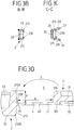
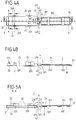
- Fig. 1A, 1B to Fig. 3A to 3D show a first embodiment of a cable marker 1, which has a housing 2 and a connected via a film hinge 4 with the housing 2 cover 3.
- Fig. 1A, 1B to Fig. 3A to 3D show the cable marker 1 in this case in an open position in which the cover 3 and the housing 2 are pivoted by 180 ° to each other and connect along a longitudinal direction L to each other.
- the lid 3 can be attached in a closing direction S bending the film hinge 4 to the housing 2, so that in a closed position enclosed by the housing 2 receiving opening 23 and closed in the receiving opening 23 marking, for example a Shield or the like, is protected.
- the cable marker 1 then, as shown schematically in FIG Fig. 7 is attached to a cable 6 and set, for example via a fastening tab 22 by a cross-cable tie 5 on the cable 6, wherein the housing 2 on a side facing away from the cable 6 carries a visible surface 20, through which a into the receiving opening 23 of Housing 2 inserted label is visible.
- the lid 3 comes to rest between the housing 2 and the cable 6, so that when attached cable marker 1, the lid 3 can not be opened.
- the housing 2 has, as stated, a visible surface 20, which is formed transparent and the receiving opening 23 limited to the outside.
- a housing box 21 which is formed by end walls 210, 212 and side walls 211, 213, which are each angled to the visible surface 20 and the receiving opening 23 border.
- a fastening tab 22 connects, each mounting patch 22 having an opening 220 through which a cable tie 5 can be performed for fixing the cable marker 1 to a cable 6.
- the lid 3, which is connected via the film hinge 4 with the housing 2, has an inner side 31, which faces in the closed position of the cable marker 1 to the receiving opening 23, while an inner side 31 opposite the outside 30 when attached to a cable 6 cable marker 1 towards the cable 6 points.
- the lid 3 On the inside 31, the lid 3 carries a rib structure, which is formed by a circumferential rib ring 310 and The rib structure which creates irregularities on the inner side 31 of the lid 3 serves to ensure that both the housing 2 as a.
- the lid 3 adhere to an ejector side of a mold, so that when removing two mold halves of the injection mold from each other tearing of the film hinge 4 is prevented as far as possible.
- the cover 3 On the outer side 30, the cover 3 has a recess 300 which extends transversely to the longitudinal direction L over the outer side 30 of the cover 3 away and in the closed position of the cable marker 1 in the region of the openings 220 of the mounting lugs 22 of the housing 2 comes to rest so that a cable tie 5 can be easily passed through the openings 220, without being hindered by the lid 3.
- the cover 3 On its side remote from the film hinge 4, the cover 3 has an actuating tab 32 which protrudes outwards in the closed position over the end wall 212 of the housing 2, so that the cover 3 can be opened by pressure on the actuating tab 32 from its closed position ,
- the hinge 4 excludes, as out Fig. 2A in synopsis with Fig. 3D can be seen, with a first base portion 40 to the end wall 210 of the housing 2 and with a second base portion 41 to an end wall 301 of the lid 3 at. Between the base portions 40, 41 extends a connecting portion 42, in the region of the film hinge 4 is bent during pivoting of the lid relative to the housing 2 in particular for closing the cable marker 1, so that the film hinge 4, in particular in the region of its connecting portion 42 have sufficient elasticity must, which allows pivoting of the lid 3 from the open position to the closed position relative to the housing 2.
- the connecting portion 42 extends with its lateral edges 420, 421 between the first base portion 40 and the second base portion 41 and thus between the housing 2 and the lid 3.
- the connecting portion 42 is in this case formed waisted and curved at its edges 420, 421 so in that a curvature results with a constant, finite radius of curvature R and thus the connecting portion 42 is notched in a concave manner on both sides.
- the width W1 of the connecting portion 42 with respect to the width W0 of Base portions 40, 41 is reduced, so that the elasticity of the film hinge 4 is increased in particular centrally of the connecting portion 42.
- the result is a ratio of the width W1 of the connecting portion 42 at its narrowest point to the width WO of the base portions 40, 41 of e.g. between 50% and 90%, preferably between 65% and 85%, for example between 70% and 80%.
- the lid 3 By means of the integrally formed with the housing 2 and the lid 3 film hinge 4, the lid 3 in a pivoting plane E (corresponding to the plane in FIG Fig. 2B ), wherein due to the sidecut of the connecting portion 42 of the film hinge 4 approximately a defined bending line D is set centrally on the film hinge 4.
- connection location 210C is in this case between edges 210A, 210B, of which a first edge 210A projects from the visible surface 20 of the housing 2 and a second edge 210B represents the transition between the end wall 210 into the visible surface 20.
- connection location 210C is arranged approximately centrally between the edges 210A, 210B on the end wall 210, with a distance H between the first base portion 40 and the first edge 210A being approximately the distance between the first base portion 40 and the second Edge 210B corresponds.
- connection location 210C being arranged between the edges 210A, 210B, in particular no predetermined breaking point is created between the film hinge 4 and the end wall 210 on the end wall 210, so that the risk of the film hinge 4 breaking off at the connection location 210C is reduced.
- the risk of demolition is further reduced by the fact that the transition between the first base portion 40 and the end wall 210 has a curvature, as shown Fig. 3D can be seen, and thus a curved, continuous transition between the first base portion 40 and the end wall 210 is provided.
- the lid 3 To close the lid 3, the lid 3 must be folded in the closing direction S towards the housing 2.
- the film hinge 4 must be guided around the first edge 210 A, which inevitably goes hand in hand with a bending of the film hinge 4 and thus an elastic loading of the film hinge 4. Due to the fact that the connection location 210 C is spaced from the first edge 210 A by the distance H, the Bending load of the film hinge 4, however, compared to an arrangement of the connection location 210C directly to the first edge 210A - reduced, wherein also the film hinge 4 is formed comparatively long in its extension length A between the housing 2 and the lid 3.
- the ratio between extension length A and distance H is here set to a value between 2 and 4, preferably between 2.5 and 3.5, for example 3.
- FIGS. 6A and 6B The preferred arrangement of the film hinge 4 with the first base portion 40 spaced from the first edge 210A is shown schematically again in FIGS. 6A and 6B clarified. While in a direct arrangement of the film hinge 4 with the first base portion 40 at the first edge 210A of the end wall 210, as in Fig. 6A shown, a predetermined breaking point is created and also a pivoting of the lid 3 in the closing direction S towards the housing 2, a comparatively small bending radius - which is associated with a large bending load of the film hinge 4 - adjusts the connection of the film hinge 4 in the embodiment according to Fig. 6B due to the distance of the first base portion 40 to the first edge 210A improved. In the closed position results in the embodiment according to Fig.
- bending moreover preferably takes place in the region of the connecting portion 42, which further reduces the bending load at the transition point to the end wall 210.
- the second connecting portion 42 is connected to an end wall 301 of the lid 3 and in this case is continuous in the thick-walled end wall 301, so that the creation of a predetermined breaking point between the film hinge 4 and the cover 3 is avoided due to the continuous, continuous transition.
- a locking projection 230 is arranged, with the lid 3 can be brought to the closing of the cable marker 1 latching engaged, so that the locking projection 230 in the closed position of the cable marker 1 engages behind the lid 3 on its outer side 30 and thus holds the lid 3 in a form-fitting manner on the housing 2.
- a similar locking projection is also arranged on the inside of the end wall 212, but not on the end wall 210, via which the lid is connected by means of the film hinge 4 to the housing 2.
- the embodiment according to Fig. 4A, 4B to Figs. 5A to 5D is substantially identical to the above-described embodiment and differs from the preceding embodiment essentially in that on the housing 2 on each side wall 211, 213 two fastening tabs 22 each having an opening 220 are provided, thus securing the cable marker first to allow an associated cable 6 via two cable tie 5. Accordingly, two recesses 300 are provided on the cover 3 on the outer side 30, which come to rest in the closed position of the cable marker 1 in the region of the openings 220 of the fastening tabs 22 and thus allow the cable tie 5 to be passed through.
- fastening straps 22 for example three fastening straps 22 on each side wall 211, 213, are also conceivable in other exemplary embodiments.
- the number of fastening straps 22 can be made dependent on the dimensioning of the cable marker 1 and its length along the longitudinal extension direction L.
- fastening devices than the illustrated fastening straps 22 can be used.
- cable ties may also be formed integrally with the housing 2 and / or the cover 3.
- fastening devices can be used in the manner of clip devices, via which the cable marker 1 can be fixed to a cable 6 in a clip-on manner.
- Fig. 7 schematically shows a cable marker 1 in a mounted on a cable 6 position.
- the cable marker 1 in this case extends along its longitudinal extension direction L, wherein the film hinge 4 is arranged for connecting the cover 3 to the housing 2 at a first end 10 of the cable marker 1, which is spaced from a second end 11 of the cable marker 1 along the longitudinal extension direction L.
- the longitudinal direction L extends in this case at least in the region of Cable marker 1 substantially parallel to a longitudinal direction L1 of the cable 6, so that the cable marker 1 along the cable 6 is arranged longitudinally.
- a cable marker of the type described here can be produced for example by means of plastic injection molding of plastic, wherein the cable marker is made in one piece, for example, polycarbonate, polyamide or polyethylene.
- a suitable plastic material can be selected that meets the requirements.
Landscapes
- Physics & Mathematics (AREA)
- General Physics & Mathematics (AREA)
- Engineering & Computer Science (AREA)
- Theoretical Computer Science (AREA)
- Details Of Indoor Wiring (AREA)
- Electric Cable Installation (AREA)
- Light Guides In General And Applications Therefor (AREA)
- Insulated Conductors (AREA)
- Cable Accessories (AREA)
Description
- Die Erfindung betrifft einen Kabelmarker nach dem Oberbegriff des Anspruch 1.
- Ein derartiger Kabelmarker umfasst ein Gehäuse, das eine Aufnahmeöffnung zum Aufnehmen einer Kennzeichnung zum Markieren eines Kabels aufweist. An das Gehäuse kann ein Deckel angesetzt werden, um in einer Schließstellung die Aufnahmeöffnung zu verschließen. Der Deckel ist über ein Filmscharnier mit dem Gehäuse einstückig verbunden derart, dass der Deckel in einer Öffnungsstellung, in der der Deckel die Aufnahmeöffnung nicht verschließt, entlang einer Schwenkebene relativ zu dem Gehäuse verschwenkbar ist.
- Ein derartiger Kabelmarker dient zur Kennzeichnung eines Kabels. Mit einem solchen Kabelmarker kann eine Kennzeichnung, beispielsweise ein Schild, ein Beschriftungsstreifen oder dergleichen, an einem Kabel angebracht werden. Die Kennzeichnung wird hierzu in die Aufnahmeöffnung des Gehäuses eingelegt, woraufhin das Gehäuse mit dem Deckel verschlossen und der Kabelmarker in der Schließstellung an dem Kabel angebracht wird.
- Ein Kabelmarker dieser Art ist beispielsweise aus der
DE 197 38 878 A1 bekannt. Der Kabelmarker derDE 197 388 78 A1 weist hierbei an einem Gehäuse einerseits und an einem Deckel andererseits Befestigungslaschen auf, über die der Kabelmarker beispielsweise mittels eines Kabelbinders an einem zugeordneten Kabel festgelegt werden kann. - Bei einem aus der
DE 10 2006 017 613 A1 bekannten Kabelmarker weist ein Gehäuse Einschuböffnungen auf, in die ein Kennzeichnungsschild eingeschoben werden kann und die über Verschlusskappen verschlossen werden können. - Aus der
DE 10 2005 046 468 A1 ist ein Namensschild mit einem Vorderteil und einem Rückenteil bekannt, bei dem das Vorderteil und das Rückenteil eine Aufnahme für ein Beschriftungsblatt bilden. - Ein gattungsgemäßer Kabelmarker ist aus dem Dokument "Systemised marking/Accompanying marker variants" der Fa. Weidmüller bekannt (Fundstelle: URL:http://cmswebdav.weidmueller.de/cms/gu_uk/Downloads/PrinCLiterature/Product%20I nformation%20Brochures/Marking%20Systems/1363670000_SystemisedMarking_Accompa nyingMarkerVarints.pdf).
- Ein Kabelmarker der hier in Rede stehenden Art weist beispielsweise an dem Gehäuse eine Sichtfläche auf, durch die hindurch eine in die Aufnahmeöffnung des Gehäuses eingelegte Kennzeichnung von außen sichtbar ist. Damit hierbei Angaben auf der Kennzeichnung gut lesbar sind, ist erforderlich, dass der Kabelmarker, der beispielsweise mit seinem Gehäuse und seinem Deckel einstückig aus Kunststoff hergestellt ist, zumindest an seiner Sichtfläche hinreichend durchsichtig ist. Gleichzeitig muss der Kabelmarker insbesondere im Bereich seines Filmscharniers derart elastisch sein, dass der Deckel ohne weiteres unter Verbiegen des Filmscharniers an das Gehäuse ansetzbar ist, ohne dass dabei das Filmscharnier zerstört wird.
- Herkömmliche Kabelmarker dieser Art werden beispielsweise einstückig aus einem elastischen Kunststoff auf Basis von Polyethylen (PE), das ein Elastizitätsmodul von z.B. 260 MPa aufweist, hergestellt. Solche Kabelmarker sind häufig zwar durchsichtig, erscheinen dabei jedoch milchig, weisen also eine nur eingeschränkte Transparenz auf.
- Ein Kabelmarker der hier in Rede stehenden Art soll verwendbar sein beispielsweise im Außenbereich oder auch in Umgebungen, in denen erhöhte Anforderungen an einen Brandschutz bestehen. Im Außenbereich bestehen aufgrund der sich ändernden Witterungsverhältnisse erhöhte Belastungen, die besondere Anforderungen an das Material des Kabelmarkers stellen, bedingt beispielsweise durch UV-Lichteinstrahlung oder den Kontakt mit Wasser. In Umgebungen, in denen erhöhte Anforderungen an einen Brandschutz bestehen, ist zwingend erforderlich, dass der Kabelmarker aus einem nicht (leicht) brennbaren Material hergestellt ist.
- Es besteht somit ein Bedürfnis nach Kabelmarkern, die in komfortabler Weise handhabbar sind, bei denen der Deckel in einfacher Weise zum Gehäuse verschwenkt und auch wieder aus seiner Schließstellung heraus geöffnet werden kann, die zudem eine gute Transparenz aufweisen und darüber hinaus die für den Einsatz erforderlichen Anforderungen beispielsweise hinsichtlich Witterungsbeständigkeit oder Brandschutz erfüllen können.
- Hierbei besteht die Schwierigkeit, dass klarsichtige Materialien, die zudem eine gute Witterungsbeständigkeit aufweisen oder erhöhte Brandschutzanforderungen erfüllen können, häufig eine reduzierte Elastizität aufweisen und somit eine einfache Materialsubstitution bei bestehenden Kabelmarkern nicht ohne weiteres möglich ist. Zudem nehmen einige Kunststoffe vergleichsweise viel Wasser auf und können durch Wasserabgabe spröde werden, was zu einer erhöhten Bruchanfälligkeit führen kann und eine Ausbildung von Filmscharnieren daher schwierig macht.
- Aufgabe der vorliegenden Erfindung ist es, einen Kabelmarker zur Verfügung zu stellen, der in komfortabler Weise handhabbar ist, dabei durchsichtig mit guter Transparenz ausgebildet werden kann und zudem für einen gewünschten Einsatz optimiert sein kann und zuverlässig herstellbar ist.
- Diese Ausgabe wird durch einen Gegenstand mit den Merkmalen des Anspruchs 1 gelöst.
- Demnach umfasst das Filmscharnier einen ersten Basisabschnitt, über den das Filmscharnier an das Gehäuse angebunden ist, einen zweiten Basisabschnitt, über den das Filmscharnier an einen Deckel angebunden ist, und einen zwischen dem ersten Basisabschnitt und dem zweiten Basisabschnitt angeordneten Verbindungsabschnitt, wobei der Verbindungsabschnitt, betrachtet entlang einer Richtung senkrecht zur Schwenkebene, eine gegenüber zumindest einem der beiden Basisabschnitte reduzierte Weite aufweist.
- Die vorliegende Erfindung geht von der Erkenntnis aus, dass eine einfache Materialsubstitution insbesondere zur Schaffung eines hochtransparenten Kabelmarkers, der hinsichtlich seines Materials für einen bestimmten Einsatzzweck optimiert ist, nicht ohne weiteres möglich ist. Ein Kunststoff, beispielsweise Polycarbonat, der eine hohe Transparenz aufweist und insbesondere nicht milchig erscheint und zudem Anforderungen an einen erhöhten Brandschutz beispielsweise in Innenanwendungen z.B. in Schienenfahrzeugen erfüllt, weist eine erhöhte Steifigkeit auf, was mit Blick auf den Kabelmarker insbesondere zur Ausbildung des Filmscharniers eine Anpassung erfordert. Dementsprechend ist im Sinne der vorliegenden Erfindung das Filmscharnier derart tailliert ausgebildet, dass es in einem Binnenabschnitt zwischen den Anbindungsstellen an das Gehäuse einerseits und den Deckel andererseits eine reduzierte Weite (betrachtet entlang einer Richtung senkrecht zur Schwenkebene) aufweist. Ausgehend von einem Basisabschnitt, über den das Filmscharnier an das Gehäuse oder den Deckel angebunden ist, verjüngt sich somit das Filmscharnier, so dass an dem Verbindungsabschnitt zwischen den Basisabschnitten eine definierte Biegelinie oder ein definierter Biegebereich geschaffen wird, in dem das Filmscharnier aufgrund seiner reduzierten Weite in einfacher, elastischer Weise gebogen werden kann.
- Die vorliegende Erfindung macht somit die Verwendung eines hochtransparenten, vergleichsweise steifen Kunststoffs zur Herstellung des Kabelmarkers möglich, ohne dass dadurch die Funktionalität des Filmscharniers beeinträchtigt ist.
- Die Weite des Verbindungsabschnitts ist reduziert zumindest gegenüber einem der beiden Basisabschnitte. Denkbar ist hierbei eine Ausgestaltung, bei der sich die Weite ausgehend von einem der Basisabschnitte reduziert und dann hin zum anderen Basisabschnitt nicht wieder erweitert. Vorzugsweise ist der Verbindungsabschnitt jedoch derart tailliert, dass die Weite des Verbindungsabschnitts kleiner ist als die Weite sowohl des ersten Basisabschnitts, über den das Filmscharnier mit dem Gehäuse verbunden ist, als auch des zweiten Basisabschnittes, über den das Filmscharnier mit dem Deckel verbunden ist. Ist der Verbindungsabschnitt zusätzlich an zumindest einem seiner Ränder, die sich zwischen dem ersten Basisabschnitt und dem zweiten Basisabschnitt erstrecken, gekrümmt ausgebildet, ergibt sich eine Taillierung des Filmscharniers mit einer Vorzugsbiegelinie an dem Ort der kleinsten Weite des Verbindungsabschnitts. Die Krümmung zumindest eines der Ränder des Verbindungsabschnitts kann hierbei beispielsweise durch einen konstanten, endlichen Krümmungsradius beschreibbar sein, so dass der Verbindungsabschnitt zumindest abschnittsweise eine konvexe Einkerbung aufweist.
- Konkret kann das Verhältnis der schmalsten Weite des Verbindungsabschnitts zur Weite des zumindest einen Basisabschnitts, gegenüber dem die Weite des Verbindungsabschnitts reduziert ist, zwischen 50 % und 90 %, vorzugsweise zwischen 65 % und 85 %, beispielsweise zwischen 70 % und 80 % betragen. Beträgt die Weite des zumindest einen Basisabschnitts 100 %, so ist die Weite des Verbindungsabschnitts an seiner schmalsten Stelle somit auf einen Wert zwischen 50 % und 90 % der Weite des zumindest einen Basisabschnitts reduziert.
- Das Gehäuse weist vorzugsweise eine Sichtfläche und eine zur Sichtfläche abgewinkelten Stirnwandung auf. Im Bereich der Sichtfläche kommt eine in die Aufnahmeöffnung des Gehäuses eingelegte Kennzeichnung, beispielsweise ein Schild oder dergleichen, zu liegen, so dass durch die Sichtfläche hindurch die Kennzeichnung sichtbar ist. Das Filmscharnier ist hierbei mit seinem ersten Basisabschnitt an der Stirnwandung des Gehäuses angeordnet, so dass über die Stirnwandung und das daran anschließende Filmscharnier eine Verbindung mit dem Deckel hergestellt ist.
- Vorzugsweise weist die Stirnwandung eine erste Kante und eine der ersten Kante gegenüberliegende, zweite Kante auf. Die Stirnwandung ist entlang der zweiten Kante mit der Sichtfläche verbunden. Die zweite Kante bildet somit den Ort, an dem die zur Sichtfläche abgewinkelte Stirnwandung in die Sichtfläche übergeht. Die erste Kante liegt der zweiten Kante gegenüber und liegt somit von der zweiten Kante ab. Der erste Basisabschnitt ist hierbei an einem Verbindungsort zwischen der ersten Kante und der zweiten Kante mit der Stirnwandung verbunden, so dass die Anbindung des Filmscharniers an die Stirnwandung an einem Ort zwischen der ersten Kante und der zweiten Kante, nicht aber unmittelbar an einer der Kanten erfolgt.
- Dies bringt zwei Vorteile mit sich. Dadurch, dass das Filmscharnier nicht unmittelbar an eine der Kanten anschließt, wird zum einen die Bildung einer Sollbruchstelle am Verbindungsort des Filmscharniers mit der Stirnwandung vermieden. Zum zweiten wird dadurch, dass das Filmscharnier an einem Verbindungsort zwischen der ersten Kante und der zweiten Kante mit der Stirnwandung verbunden ist, die Biegung des Filmscharniers in der Schließstellung des Kabelmarkers reduziert, weil beim Verschwenken des Deckels zum Schließen des Kabelmarkers das Filmscharnier um die erste Kante herumgeführt werden muss. Dadurch, dass der Verbindungsort, an dem das Filmscharnier an die Stirnwandung angebunden ist, von dieser ersten Kante beabstandet ist, ergibt sich in der Schließstellung ein vergleichsweise großer Biegeradius des Filmscharniers, was insbesondere die Bruchanfälligkeit des Filmscharniers reduzieren kann.
- In einer konkreten Ausgestaltung kann der Verbindungsort, an dem das Filmscharnier an die Stirnwandung anschließt, beispielsweise gleichbeabstandet zur ersten Kante und zur zweiten Kante angeordnet sein. Der Verbindungsort befindet sich somit mittig zwischen der ersten Kante und der zweiten Kante.
- Zum Überführen des Deckels in die Schließstellung wird der Deckel um die erste Kante der Stirnwandung herumgeschwenkt. Hierbei hat sich ergeben, dass vorzugsweise das Verhältnis zwischen dem Abstand des Verbindungsorts zur ersten Kante und der Erstreckungslänge des Filmscharniers zwischen dem Gehäuse und dem Deckel vorteilhafterweise in bestimmter Weise gewählt wird, um einerseits eine komfortable, leichte Verschwenkbarkeit zu ermöglichen und andererseits das Risiko für einen Bruch an dem Filmscharnier nach Möglichkeit zu reduzieren. So wird das Verhältnis zwischen Erstreckungslänge und Abstand vorteilhafterweise auf einen Wert zwischen 2 und 4, vorzugsweise zwischen 2,5 und 3,5, beispielsweise 3, eingestellt. Die Erstreckungslänge des Filmscharniers zwischen dem Gehäuse und dem Deckel beträgt somit beispielsweise das Dreifache des Abstands zwischen dem Verbindungsort, an dem das Filmscharnier an die Stirnwandung des Gehäuses angebunden ist, und der ersten Kante, um die herum das Filmscharnier zum Schließen des Deckels zu schwenken ist.
- Vorteilhafterweise ist der zweite Basisabschnitt, über den das Filmscharnier mit dem Deckel verbunden ist, mit einer Stirnwandung des Deckels verbunden. Hierbei ist nicht notwendigerweise erforderlich, dass ein Verbindungsort, an dem der zweite Basisabschnitt an die Stirnwandung des Deckels angebunden ist, von den Kanten der Stirnwandung beabstandet ist. Insbesondere kann die Stirnwandung des Deckels derart in den zweiten Basisabschnitt des Filmscharniers übergehen, dass eine Bruchgefahr am Übergang zwischen dem Filmscharnier und der Stirnwandung des Deckels weitestgehend reduziert ist.
- Der Deckel weist vorzugsweise an einer Seite, die von der den Filmscharnier tragenden Stirnwandung abgewandt ist, eine Betätigungslasche zum Lösen des Deckels aus der Schließstellung heraus auf. Diese Betätigungslasche ist beispielsweise nach Art eines Vorsprungs ausgebildet, der in der Schließstellung des Kabelmarkers über einen Gehäusekasten des Gehäuses hinaus nach außen hin vorsteht, so dass er manuell von einem Nutzer gegriffen und betätigt werden kann, um den Deckel aus seiner Schließstellung zu lösen und den Kabelmarker zu öffnen. Eine solche Betätigungslasche kann aufgrund der Herstellung des Kabelmarkers aus einem steiferen Material erforderlich sein, weil aufgrund der erhöhten Steifigkeit des Materials ein Verwinden und Verformen des Kabelmarkers in sich nicht ohne weiteres möglich ist und somit ein Lösen des Deckels aus der Schließstellung durch Verformung des Gehäuses nicht ohne weiteres, zumindest nicht in komfortabler Weise erreicht werden kann. Mittels der Betätigungslasche kann der Deckel somit in einfacher Weise geöffnet werden, ohne dass das Gehäuse hierfür verformt werden muss.
- Das Gehäuse weist vorzugsweise einen die Aufnahmeöffnung einfassenden Gehäusekasten auf, wobei der Gehäusekasten beispielsweise durch an die Sichtfläche anschließende Stirnwandungen und Seitenwandungen gebildet ist, die sich in abgewinkelter Weise zur Sichtfläche erstrecken und einen Kasten um die Aufnahmeöffnung des Gehäuses an der Sichtfläche bilden. An dem Gehäusekasten, insbesondere an einem von der Sichtfläche abliegenden Rand des Gehäusekastens, ist hierbei ein Rastvorsprung vorgesehen, der nach innen in Richtung der Aufnahmeöffnung vorspringt und mit dem Deckel formschlüssig in Eingriff gebracht werden kann. Zum Schließen wird der Deckel an das Gehäuse angesetzt und in die Aufnahmeöffnung des Gehäuses hineingedrückt, bis der Rastvorsprung den Deckel hintergreift und somit formschlüssig an dem Gehäuse hält. Der vorzugsweise einstückig mit dem Gehäuse ausgebildete Rastvorsprung ist hierbei vergleichsweise dünn ausgebildet und ist somit hinreichend elastisch, so dass der Deckel unter Verformung des Rastvorsprungs an dem Rastvorsprung vorbeibewegt werden kann, um den Deckel rastend unter Formschluss mit dem Rastvorsprung in Eingriff zu bringen.
- Das Gehäuse weist vorzugsweise mindestens eine Befestigungseinrichtung zur Befestigung an einem Kabel auf. Eine solche Befestigungseinrichtung kann beispielsweise durch eine oder mehrere Befestigungslaschen an dem Gehäuse gebildet sein, durch die hindurch beispielsweise ein Kabelbinder geführt werden kann, um über den Kabelbinder den Kabelmarker an einem zugeordneten Kabel festzulegen. Eine solche Befestigungseinrichtung kann jedoch auch bereits einen Kabelbinder verwirklichen, so dass in einem solchen Fall ein Kabelbinder einstückig in den Kabelmarker integriert ist und somit ein direktes Festlegen an einem Kabel möglich ist. Ebenso ist denkbar, die Befestigungseinrichtung beispielsweise durch Clipselemente auszubilden, mittels derer der Kabelmarker in clipsender Weise formschlüssig an einem Kabel festgelegt werden kann.
- Der Kabelmarker erstreckt sich in der Schließstellung vorzugsweise entlang einer Längserstreckungsrichtung. Der Kabelmarker ist somit längserstreckt und insbesondere zur Aufnahme von länglichen Kennzeichnungen wie Schildern oder dergleichen geeignet. Das Filmscharnier ist hierbei beispielsweise an einem Ende des Kabelmarkers angeordnet, das von einem anderen Ende des Kabelmarkers entlang der Längserstreckungsrichtung beabstandet ist. Das Filmscharnier befindet sich somit an einer Schmalseite des Kabelmarkers.
- Vorteilhafterweise ist der Kabelmarker hierbei mit seiner Längserstreckungsrichtung entlang einer Längserstreckungsrichtung des Kabels anzuordnen. Die Längserstreckungsrichtung des Kabelmarkers und die Längserstreckungsrichtung des Kabels verlaufen somit parallel zueinander.
- Der Kabelmarker wird aus Kunststoff mittels Kunststoffspritzgießen hergestellt. Die Herstellung des Kabelmarkers erfolgt hierbei vorzugsweise in einer Stellung, in der der Deckel nicht an das Gehäuse angesetzt und somit nicht geschlossen ist. Vorzugsweise ist der Deckel bei der Herstellung vielmehr um 180° zum Gehäuse verschwenkt und befindet sich somit in einer Öffnungsstellung, in der das Filmscharnier sich geradlinig zwischen dem Deckel und dem Gehäuse erstreckt und somit elastisch nicht belastet ist.
- Zur Herstellung mittels Kunststoffspritzgießen ist hierbei das Gehäuse mit seiner Aufnahmeöffnung sowie der Deckel mit einer Innenseite einer so genannten Auswerferseite eines Kunststoffspritzgießwerkzeugs zugewandt, also einer Seite des Spritzgießwerkzeugs, an der geeignete Auswerferwerkzeuge zum Auswerfen des geformten Formteils wirken. Die Sichtfläche des Gehäuses sowie eine der Innenseite gegenüberliegende Außenseite des Deckels sind demgegenüber einer so genannten Düsenseite des Spritzgießwerkzeugs zugewandt. Um beim Entformen des mittels Kunststoffspritzgießen geformten Formstücks zu erreichen, dass die Düsenseite des Spritzgießwerkzeugs ohne weiteres von dem Gehäuse und dem Deckel gelöst werden kann, das Formstück mit dem Gehäuse und dem Deckel jedoch zunächst an der Auswerferseite des Spritzgießwerkzeugs haften bleibt, sind vorzugsweise an der der Auswerferseite des Spritzgießwerkzeugs zugewandten Innenseite des Deckels eine oder mehrere Erhebungen und/oder Vertiefungen, beispielsweise in Form von Rippen, angebracht, die eine Unregelmäßigkeit an der Innenseite des Deckels schaffen und somit die Haftung des Deckels an der Auswerferseite des Spritzgießwerkzeugs erhöhen. Unter Wirkung von geeigneten Auswerferwerkzeugen kann dann das Formstück mit seinem Gehäuse und Deckel aus dem Werkzeug entformt und ausgeworfen werden.
- Weil durch Schaffung einer (Rippen-)Struktur an dem Deckel sichergestellt wird, dass auch der Deckel beim Entformen aus einem Spritzgießwerkzeug an der Auswerferseite des Spritzgießwerkzeugs haften bleibt, kann insbesondere vermieden werden, dass beim Entfernen der die Auswerferseite und die Düsenseite ausbildenden Werkzeughälften voneinander der Deckel an der Düsenseite haften bleibt, was ansonsten zu einem Abreißen des Filmscharniers führen könnte.
- Der Kabelmarker wird, wie bereits beschrieben, einstückig mittels Kunststoffspritzgießen hergestellt. Unterschiedliche Werkstoffe kommen hierbei zur Herstellung des Kabelmarkers in Betracht. Bevorzugt sind hierbei Kunststoffe, die eine hohe Transparenz aufweisen und nicht milchig erscheinen. Abhängig vom Einsatzgebiet des Kabelmarkers wird hierbei ein solcher Kunststoff ausgewählt, der die durch das Einsatzgebiet bedingten Anforderungen erfüllen kann. Soll der Kabelmarker beispielsweise in einer Umgebung mit erhöhten Brandschutzanforderungen, beispielsweise in einem Schienenfahrzeug, eingesetzt werden, so kann ein Polycarbonat (PC) verwendet werden. Soll der Kabelmarker beispielsweise in Außenanwendungen mit erhöhten Anforderungen an eine Witterungsbeständigkeit zum Einsatz kommen, kann ein Polyamid (PA) verwendet werden. Solche Kunststoffe können ein vergleichsweise großes Elastizitätsmodul (E-Modul), beispielsweise ein Elastizitätsmodul größer als 1000 MPa oder gar größer als 1500 MPa, aufweisen.
- Vorzugsweise ist der Kunststoff hoch-transparent mit einer Lichtdurchlässigkeit (nD) größer 80%, vorzugsweise größer 85%. Der Kabelmarker ist somit durchsichtig, so dass eine in der Aufnahmeöffnung des Kabelmarkers angeordnete Kennzeichnung von außen gut lesbar ist.
- Der der Erfindung zugrunde liegende Gedanke soll nachfolgend anhand der in den Figuren dargestellten Ausführungsbeispiele näher erläutert werden. Es zeigen:
- Fig. 1A
- eine perspektivische Ansicht eines Kabelmarkers;
- Fig. 1B
- eine andere perspektivische Ansicht des Kabelmarkers;
- Fig. 2A
- eine Draufsicht auf den Kabelmarker in einer Öffnungsstellung;
- Fig. 2B
- eine Seitenansicht des Kabelmarkers gemäß
Fig. 2A ; - Fig. 3A
- eine Schnittansicht entlang der Linie A-A gemäß
Fig. 2A ; - Fig. 3B
- eine Schnittansicht entlang der Linie B-B gemäß
Fig. 2A ; - Fig. 3C
- eine Schnittansicht entlang der Linie C-C gemäß
Fig. 2A ; - Fig. 3D
- eine vergrößerte Ansicht des Ausschnitts X gemäß
Fig. 3A ; - Fig. 4A
- eine Draufsicht auf ein anderes Ausführungsbeispiel eines Kabelmarkers;
- Fig. 4B
- eine Seitenansicht des Kabelmarkers gemäß
Fig. 4A ; - Fig. 5A
- eine Schnittansicht entlang der Linie A-A gemäß
Fig. 4A ; - Fig. 5B
- eine Schnittansicht entlang der Linie B-B gemäß
Fig. 4A ; - Fig. 5C
- eine Schnittansicht entlang der Linie C-C gemäß
Fig. 4A ; - Fig. 5D
- eine vergrößerte Ansicht des Ausschnitts X gemäß
Fig. 5A ; - Fig. 6A
- eine schematische Ansicht der Anbindung eines Filmscharniers an eine Stirnwandung eines Gehäuses eines Kabelmarkers in einem ersten Ausführungsbeispiel;
- Fig. 6B
- eine schematische Ansicht der Anbindung des Filmscharniers an die Stirnwandung des Gehäuses in einem bevorzugten, zweiten Ausführungsbeispiel; und
- Fig. 7
- eine schematische Ansicht eines an einem Kabel angeordneten Kabelmarkers.
-
Fig. 1A, 1B bisFig. 3A bis 3D zeigen ein erstes Ausführungsbeispiel eines Kabelmarkers 1, der ein Gehäuse 2 und einen über ein Filmscharnier 4 mit dem Gehäuse 2 verbundenen Deckel 3 aufweist.Fig. 1A, 1B bisFig. 3A bis 3D zeigen den Kabelmarker 1 hierbei in einer Öffnungsstellung, in der der Deckel 3 und das Gehäuse 2 um 180° zueinander verschwenkt sind und entlang einer Längserstreckungsrichtung L aneinander anschließen. Zum Schließen des Kabelmarkers 1 kann der Deckel 3 in eine Schließrichtung S unter Verbiegen des Filmscharniers 4 an das Gehäuse 2 angesetzt werden, so dass in einer Schließstellung eine durch das Gehäuse 2 eingefasste Aufnahmeöffnung 23 verschlossen und eine in die Aufnahmeöffnung 23 eingelegte Kennzeichnung, beispielsweise ein Schild oder dergleichen, geschützt ist. - In der Schließstellung kann der Kabelmarker 1 dann, wie schematisch in
Fig. 7 dargestellt ist, an ein Kabel 6 angesetzt und beispielsweise über einen eine Befestigungslasche 22 durchgreifenden Kabelbinder 5 an dem Kabel 6 festgelegt werden, wobei das Gehäuse 2 an einer dem Kabel 6 abgewandten Seite eine Sichtfläche 20 trägt, durch die hindurch eine in die Aufnahmeöffnung 23 des Gehäuses 2 eingelegte Kennzeichnung sichtbar ist. Bei an das Kabel 6 angesetztem Kabelmarker 1 kommt der Deckel 3 zwischen dem Gehäuse 2 und dem Kabel 6 zu liegen, so dass bei angesetztem Kabelmarker 1 der Deckel 3 nicht geöffnet werden kann. - Das Gehäuse 2 weist, wie gesagt, eine Sichtfläche 20 auf, die durchsichtig ausgebildet ist und die Aufnahmeöffnung 23 nach außen hin begrenzt. An die Sichtfläche 20 schließt, wie aus
Fig. 1A und 1B ersichtlich, ein Gehäusekasten 21 an, der durch Stirnwandungen 210, 212 und Seitenwandungen 211, 213 gebildet ist, die jeweils zur Sichtfläche 20 abgewinkelt sind und die Aufnahmeöffnung 23 einfassen. An die Seitenwandungen 211, 213 schließt jeweils eine Befestigungslasche 22 an, wobei jede Befestigungslache 22 eine Öffnung 220 aufweist, durch die hindurch ein Kabelbinder 5 zum Festlegen des Kabelmarkers 1 an einem Kabel 6 geführt werden kann. - Der Deckel 3, der über das Filmscharnier 4 mit dem Gehäuse 2 verbunden ist, weist eine Innenseite 31 auf, die in der Schließstellung des Kabelmarkers 1 hin zur Aufnahmeöffnung 23 weist, während eine der Innenseite 31 gegenüberliegende Außenseite 30 bei an einem Kabel 6 angebrachtem Kabelmarker 1 hin zum Kabel 6 weist. An der Innenseite 31 trägt der Deckel 3 eine Rippenstruktur, die gebildet ist durch einen umlaufenden Rippenring 310 und eine quer zur Längserstreckungsrichtung L über die Innenseite 31 erstreckte Rippe 311. Die Rippenstruktur, die Unregelmäßigkeiten an der Innenseite 31 des Deckels 3 schafft, dient dazu, bei einem Entformen des mittels Kunststoffspritzgießen hergestellten Kabelmarkers 1 aus einem Spritzgießwerkzeug sicherzustellen, dass sowohl das Gehäuse 2 als auch der Deckel 3 an einer Auswerferseite einer Werkzeugform haften bleiben, so dass bei dem Entfernen zweier Werkzeughälften des Spritzgießwerkzeugs voneinander ein Abreißen des Filmscharniers 4 nach Möglichkeit verhindert ist.
- An der Außenseite 30 weist der Deckel 3 eine Aussparung 300 auf, die sich quer zur Längserstreckungsrichtung L über die Außenseite 30 des Deckels 3 hinweg erstreckt und in der Schließstellung des Kabelmarkers 1 im Bereich der Öffnungen 220 der Befestigungslaschen 22 des Gehäuses 2 zu liegen kommt, so dass ein Kabelbinder 5 ohne weiteres durch die Öffnungen 220 hindurchgeführt werden kann, ohne dass dies durch den Deckel 3 behindert wird.
- An seiner vom Filmscharnier 4 abliegenden Seite weist der Deckel 3 eine Betätigungslasche 32 auf, die in der Schließstellung über die Stirnwandung 212 des Gehäuses 2 nach außen hin vorsteht, so dass der Deckel 3 durch Druck an der Betätigungslasche 32 aus seiner Schließstellung heraus geöffnet werden kann.
- Das Filmscharnier 4 schließt, wie aus
Fig. 2A in Zusammenschau mitFig. 3D ersichtlich ist, mit einem ersten Basisabschnitt 40 an die Stirnwandung 210 des Gehäuses 2 und mit einem zweiten Basisabschnitt 41 an eine Stirnwandung 301 des Deckels 3 an. Zwischen den Basisabschnitten 40, 41 erstreckt sich ein Verbindungsabschnitt 42, im Bereich dessen das Filmscharnier 4 beim Verschwenken des Deckels relativ zum Gehäuse 2 insbesondere zum Schließen des Kabelmarkers 1 gebogen wird, so dass das Filmscharnier 4 insbesondere im Bereich seines Verbindungsabschnitts 42 eine hinreichende Elastizität aufweisen muss, die ein Verschwenken des Deckels 3 aus der Öffnungsstellung in die Schließstellung relativ zum Gehäuse 2 ermöglicht. - Der Verbindungsabschnitt 42 erstreckt sich mit seinen seitlichen Rändern 420, 421 zwischen dem ersten Basisabschnitt 40 und dem zweiten Basisabschnitt 41 und somit zwischen dem Gehäuse 2 und dem Deckel 3. Der Verbindungsabschnitt 42 ist hierbei tailliert ausgebildet und dazu an seinen Rändern 420, 421 derart gekrümmt, dass sich eine Krümmung mit einem konstanten, endlichen Krümmungsradius R ergibt und der Verbindungsabschnitt 42 somit in konkaver Weise beidseitig eingekerbt ist. Auf diese Weise ist die Weite W1 des Verbindungsabschnitts 42 gegenüber der Weite W0 der Basisabschnitte 40, 41 reduziert, so dass die Elastizität des Filmscharniers 4 insbesondere mittig am Verbindungsabschnitt 42 erhöht ist.
- Es ergibt sich ein Verhältnis der Weite W1 des Verbindungsabschnitts 42 an seiner schmalsten Stelle zur Weite WO der Basisabschnitte 40, 41 von z.B. zwischen 50 % und 90 %, vorzugsweise zwischen 65 % und 85 %, beispielsweise zwischen 70 % und 80 %.
- Mittels des einstückig mit dem Gehäuse 2 und dem Deckel 3 ausgebildeten Filmscharniers 4 kann der Deckel 3 in einer Schwenkebene E (entsprechend der Zeichenebene in
Fig. 2B ) verschwenkt werden, wobei sich aufgrund der Taillierung des Verbindungsabschnitts 42 des Filmscharniers 4 näherungsweise eine definierte Biegelinie D mittig am Filmscharnier 4 einstellt. - Wie aus
Fig. 3D ersichtlich, ist das Filmscharnier 4 mit seinem ersten Basisabschnitt 40 an einem Verbindungsort 210C an die Stirnwandung 210 angebunden. Der Verbindungsort 210C befindet sich hierbei zwischen Kanten 210A, 210B, von denen eine erste Kante 210A von der Sichtfläche 20 des Gehäuses 2 abliegt und eine zweite Kante 210B den Übergang zwischen der Stirnwandung 210 in die Sichtfläche 20 darstellt. Der Verbindungsort 210C ist hierbei in etwa mittig zwischen den Kanten 210A, 210B an der Stirnwandung 210 angeordnet, wobei sich ein Abstand H zwischen dem ersten Basisabschnitt 40 und der ersten Kante 210A ergibt, der in etwa dem Abstand zwischen dem ersten Basisabschnitt 40 und der zweiten Kante 210B entspricht. - Dadurch, dass der Verbindungsort 210C zwischen den Kanten 210A, 210B angeordnet ist, wird insbesondere an der Stirnwandung 210 keine Sollbruchstelle zwischen dem Filmscharnier 4 und der Stirnwandung 210 geschaffen, so dass das Risiko eines Abbrechens des Filmscharniers 4 an dem Verbindungsort 210C reduziert ist. Das Abbruchrisiko ist weiter dadurch reduziert, dass der Übergang zwischen dem ersten Basisabschnitt 40 und der Stirnwandung 210 mit einer Krümmung behaftet ist, wie aus
Fig. 3D ersichtlich ist, und somit ein gekrümmter, stetiger Übergang zwischen dem ersten Basisabschnitt 40 und der Stirnwandung 210 geschaffen wird. - Zum Schließen des Deckels 3 muss der Deckel 3 in die Schließrichtung S hin zum Gehäuse 2 geklappt werden. Dazu muss das Filmscharnier 4 um die erste Kante 210 A herumgeführt werden, was zwangsläufig mit einer Verbiegung des Filmscharniers 4 und somit einer elastischen Belastung des Filmscharniers 4 einhergeht. Dadurch, dass der Verbindungsort 210C von der ersten Kante 210A um den Abstand H beabstandet ist, wird die Biegebelastung des Filmscharniers 4 jedoch - gegenüber einer Anordnung des Verbindungsortes 210C unmittelbar an der ersten Kante 210A - reduziert, wobei zudem das Filmscharnier 4 in seiner Erstreckungslänge A zwischen dem Gehäuse 2 und dem Deckel 3 vergleichsweise lang ausgebildet ist. Vorzugsweise wird das Verhältnis zwischen Erstreckungslänge A und Abstand H hierbei auf einen Wert zwischen 2 und 4, vorzugsweise zwischen 2,5 und 3,5, beispielsweise 3, eingestellt.
- Die bevorzugte Anordnung des Filmscharniers 4 mit dem ersten Basisabschnitt 40 beabstandet zur ersten Kante 210A ist schematisch noch einmal in
Fig. 6A und 6B verdeutlicht. Während bei einer unmittelbaren Anordnung des Filmscharniers 4 mit dem ersten Basisabschnitt 40 an der ersten Kante 210A der Stirnwandung 210, wie inFig. 6A dargestellt, eine Sollbruchstelle geschaffen wird und zudem sich bei einem Verschwenken des Deckels 3 in die Schließrichtung S hin zum Gehäuse 2 ein vergleichsweise kleiner Biegeradius - der mit einer großen Biegebelastung des Filmscharniers 4 einhergeht - einstellt, ist die Anbindung des Filmscharniers 4 bei der Ausgestaltung gemäßFig. 6B aufgrund des Abstands des ersten Basisabschnitts 40 zur ersten Kante 210A verbessert. In der Schließstellung ergibt sich bei der Ausgestaltung gemäßFig. 6B ein größerer Biegeradius an dem Filmscharnier 4, wobei das Filmscharnier 4 länger ausgebildet ist, um einerseits ein Einklappen des Deckels 3 um die erste Kante 210A herum zu ermöglichen und gleichzeitig die Biegebelastung des Filmscharniers 4 in der Schließstellung weiter zu reduzieren. - Bei der vorgeschlagenen Ausgestaltung mit einem taillierten Verbindungsabschnitt 42 findet ein Verbiegen zudem vorzugsweise im Bereich des Verbindungsabschnitts 42 statt, was die Biegebelastung am Übergangspunkt zur Stirnwandung 210 weiter reduziert.
- Der zweite Verbindungsabschnitt 42 ist mit einer Stirnwandung 301 des Deckels 3 verbunden und geht hierbei stetig in die dickwandige Stirnwandung 301 über, so dass aufgrund des kontinuierlichen, stetigen Übergangs die Schaffung einer Sollbruchstelle zwischen dem Filmscharnier 4 und dem Deckel 3 vermieden ist.
- Wie aus
Fig. 3B und 3C ersichtlich, ist an den Seitenwandungen 211, 213 des Gehäuses 2 jeweils innenliegend und vorspringend hin zur Aufnahmeöffnung 23 ein Rastvorsprung 230 angeordnet, mit dem der Deckel 3 zum Schließen des Kabelmarkers 1 rastend in Eingriff gebracht werden kann, so dass der Rastvorsprung 230 in der Schließstellung des Kabelmarkers 1 den Deckel 3 an seiner Außenseite 30 hintergreift und somit den Deckel 3 formschlüssig an dem Gehäuse 2 hält. Ein ebensolcher Rastvorsprung ist auch innenliegend an der Stirnwandung 212 angeordnet, nicht jedoch an der Stirnwandung 210, über die der Deckel mittels des Filmscharniers 4 an das Gehäuse 2 angebunden ist. - Das Ausführungsbeispiel gemäß
Fig. 4A, 4B bisFig. 5A bis 5D ist im Wesentlichen identisch zu dem vorangehend geschilderten Ausführungsbeispiel und unterscheidet sich von dem vorangehenden Ausführungsbeispiel im Wesentlich dadurch, dass an dem Gehäuse 2 an jeder Seitenwandung 211, 213 jeweils zwei Befestigungslaschen 22 mit jeweils einer Öffnung 220 vorgesehen sind, um somit ein Befestigen des Kabelmarkers 1 an einem zugeordneten Kabel 6 über zwei Kabelbinder 5 zu ermöglichen. Entsprechend sind an dem Deckel 3 an der Außenseite 30 zwei Aussparungen 300 vorgesehen, die in der Schließstellung des Kabelmarkers 1 im Bereich der Öffnungen 220 der Befestigungslaschen 22 zu liegen kommen und somit ein Durchführen der Kabelbinder 5 ermöglichen. - Ansonsten ist das Ausführungsbeispiel funktional identisch zu dem vorangehend erläuterten Ausführungsbeispiel, so dass vollständig auf das vorangehend Erläuterte verwiesen werden soll.
- Denkbar sind bei anderen Ausführungsbeispielen grundsätzlich auch mehr Befestigungslaschen 22, beispielsweise drei Befestigungslaschen 22 an jeder Seitenwandung 211, 213. Die Anzahl der Befestigungslaschen 22 kann von der Dimensionierung des Kabelmarkers 1 und seiner Länge entlang der Längserstreckungsrichtung L abhängig gemacht werden.
- In diesem Zusammenhang sei angemerkt, dass grundsätzlich auch andere Befestigungseinrichtungen als die dargestellten Befestigungslaschen 22 verwendet werden können. Beispielsweise können Kabelbinder auch einstückig mit dem Gehäuse 2 und/oder dem Deckel 3 ausgebildet sein. Oder es können Befestigungseinrichtungen nach Art von Clipseinrichtungen verwendet werden, über die der Kabelmarker 1 clipsend an einem Kabel 6 festgelegt werden kann.
-
Fig. 7 zeigt schematisch einen Kabelmarker 1 in einer an einem Kabel 6 angebrachten Stellung. Der Kabelmarker 1 erstreckt sich hierbei entlang seiner Längserstreckungsrichtung L, wobei das Filmscharnier 4 zur Verbindung des Deckels 3 mit dem Gehäuse 2 an einem ersten Ende 10 des Kabelmarkers 1 angeordnet ist, das von einem zweiten Ende 11 des Kabelmarkers 1 entlang der Längserstreckungsrichtung L beabstandet ist. Die Längserstreckungsrichtung L verläuft hierbei zumindest im Bereich des Kabelmarkers 1 im Wesentlichen parallel zu einer Längserstreckungsrichtung L1 des Kabels 6, so dass der Kabelmarker 1 längs entlang des Kabels 6 angeordnet ist. - Der der Erfindung zugrunde liegende Gedanke ist nicht auf die vorangehend geschilderten Ausführungsbeispiele beschränkt, sondern lässt sich grundsätzlich auch in gänzlich anders gearteten Ausführungsformen verwirklichen.
- Ein Kabelmarker der hier beschriebenen Art kann beispielsweise mittels Kunststoffspritzgießen aus Kunststoff hergestellt sein, wobei der Kabelmarker einstückig beispielsweise aus Polycarbonat, Polyamid oder Polyethylen gefertigt ist. Abhängig vom Einsatzgebiet des Kabelmarkers in einem Außenbereich oder in einer Umgebung, die besondere Anforderungen an einen Brandschutz stellt, kann hierbei ein geeignetes Kunststoffmaterial ausgewählt werden, das die gestellten Anforderungen erfüllt.
- Durch die besondere Ausgestaltung des Kabelmarkers insbesondere mit seinem Filmscharnier wird auch die Verwendung vergleichsweise steifer Kunststoffmaterialien möglich. Dies ermöglicht zum einen die Verwendung des Kabelmarkers in ganz unterschiedlichen Einsatzgebieten und zum zweiten die Herstellung aus einem hochtransparenten Material mit einer Lichtdurchlässigkeit nD > 80 %, insbesondere > 85 %.
-
- 1
- Kabelmarker
- 10, 11
- Ende
- 2
- Gehäuse
- 20
- Sichtfläche
- 21
- Gehäusekasten
- 210, 212
- Stirnwandung
- 210A, 210B
- Kante
- 210C
- Verbindungsort
- 211, 213
- Seitenwandung
- 22
- Befestigungslasche
- 220
- Öffnung
- 23
- Aufnahmeöffnung
- 230
- Rastvorsprung
- 3
- Deckel
- 30
- Außenseite
- 300
- Aussparung
- 301
- Stirnwandung
- 31
- Innenseite
- 310, 311
- Rippen
- 32
- Betätigungslasche
- 4
- Filmscharnier
- 40, 41
- Basisabschnitt
- 42
- Verbindungsabschnitt
- 420, 421
- Rand
- 5
- Verbindungselement
- 6
- Kabel
- A
- Länge
- D
- Biegelinie
- E
- Schwenkebene
- H
- Abstand
- L, L1
- Längserstreckungsrichtung
- R
- Krümmungsradius
- S
- Schließrichtung
- W0, W1
- Weite
Claims (13)
- Kabelmarker (1), mit- einem Gehäuse (2), das eine Aufnahmeöffnung (23) zum Aufnehmen einer Kennzeichnung zum Markieren eines Kabels (6) aufweist,- einem Deckel (3) zum Verschließen der Aufnahmeöffnung (23) in einer Schließstellung, wobei der Kabelmarker (1) in der Schließstellung an dem Kabel (6) anbringbar ist, und- einem Filmscharnier (4), über den das Gehäuse (2) einstückig mit dem Deckel (3) verbunden ist derart, dass der Deckel (3) in einer Öffnungsstellung, in der der Deckel (3) die Aufnahmeöffnung (23) nicht verschließt, entlang einer Schwenkebene (E) relativ zu dem Gehäuse (2) verschwenkbar ist,wobei dass das Filmscharnier (4) einen ersten Basisabschnitt (40), über den das Filmscharnier (4) an das Gehäuse (2) angebunden ist, einen zweiten Basisabschnitt (41), über den das Filmscharnier (4) an dem Deckel (3) angebunden ist, und einen zwischen dem ersten Basisabschnitt (40) und dem zweiten Basisabschnitt (41) angeordneten Verbindungsabschnitt (42) aufweist, wobei der Verbindungsabschnitt (42), betrachtet entlang einer Richtung senkrecht zur Schwenkebene (E), eine gegenüber zumindest einem der Basisabschnitte (40, 41) reduzierte Weite (W1) aufweist,
wobei der Kabelmarker (1) einstückig mittels Kunststoffspritzgießen gefertigt ist, dadurch gekennzeichnet,
dass der Deckel (3) an einer in der Schließstellung der Aufnahmeöffnung (23) des Gehäuses (2) zugewandten Innenseite (31) mindestens eine Erhebung und/oder Vertiefung, beispielsweise eine Rippe (310, 311), zur Schaffung einer Unregelmäßigkeit an der Innenseite (31) aufweist. - Kabelmarker (1) nach Anspruch 1, dadurch gekennzeichnet, dass die Weite (W1) des Verbindungsabschnitts (42) kleiner ist als die Weite (W0) des ersten Basisabschnitts (40) und des zweiten Basisabschnitts (41).
- Kabelmarker (1) nach Anspruch 1 oder 2, dadurch gekennzeichnet, dass der Verbindungsabschnitt (42) sich senkrecht zur Schwenkebene (E) erstreckt und einen ersten Rand (420) und eine zweiten Rand (421) aufweist, wobei der erste Rand (420) und der zweite Rand (421) sich jeweils zwischen dem ersten Basisabschnitt (40) und dem zweiten Basisabschnitt (41) erstrecken und betrachtet entlang einer Richtung senkrecht zur Schwenkebene (E) voneinander beabstandet sind, wobei der erste und/oder zweite Rand (420, 421) gekrümmt sind.
- Kabelmarker (1) nach einem der Ansprüche 1 bis 3, dadurch gekennzeichnet, dass das Verhältnis der schmalsten Weite (W1) des Verbindungsabschnitts (42) zur Weite (W0) des zumindest einen Basisabschnitts (40, 41) zwischen 50% und 90%, vorzugsweise zwischen 65% und 85% beträgt.
- Kabelmarker (1) nach einem der vorangehenden Ansprüche, dadurch gekennzeichnet, dass das Gehäuse (2) eine Sichtfläche (20) und eine zur Sichtfläche abgewinkelte Stirnwandung (210) aufweist, wobei das Filmscharnier (4) mit dem ersten Basisabschnitt (40) an der Stirnwandung (210) des Gehäuses (2) angeordnet ist.
- Kabelmarker (1) nach Anspruch 5, dadurch gekennzeichnet, dass die Stirnwandung (210) eine erste Kante (210A) und eine der ersten Kante (210A) gegenüberliegende, zweite Kante (210B) aufweist, wobei die Stirnwandung (210) entlang der zweiten Kante (210B) mit der Sichtfläche (20) verbunden ist und der erste Basisabschnitt (40) an einem Verbindungsort (210C) zwischen der ersten Kante (210A) und der zweiten Kante (210B) mit der Stirnwandung (210) verbunden ist.
- Kabelmarker (1) nach Anspruch 6, dadurch gekennzeichnet, dass der Verbindungsort (210C) gleichbeabstandet zur ersten Kante (210A) und zur zweiten Kante (210B) ist.
- Kabelmarker (1) nach Anspruch 6 oder 7, dadurch gekennzeichnet, dass der Deckel (3) zum Überführen in die Schließstellung um die erste Kante (210A) herum zu schwenken ist, wobei der Verbindungsort (210C) einen Abstand (A) zur ersten Kante (210A) und das Filmscharnier (4) eine Erstreckungslänge (A) zwischen dem Gehäuse (2) und dem Deckel (3) aufweist derart, dass das Verhältnis von Erstreckungslänge (A) zu Abstand (H) zwischen 2 und 4, vorzugsweise zwischen 2,5 und 3,5, beispielsweise 3, beträgt.
- Kabelmarker (1) nach einem der vorangehenden Ansprüche, dadurch gekennzeichnet, dass der zweite Basisabschnitt (41) mit einer Stirnwandung (301) des Deckels (3) verbunden ist und der Deckel (3) an einer von der Stirnwandung (301) abgewandten Seite eine Betätigungslasche (32) zum Lösen des Deckels (3) aus der Schließstellung aufweist.
- Kabelmarker (1) nach einem der vorangehenden Ansprüche, dadurch gekennzeichnet, dass das Gehäuse (2) einen die Aufnahmeöffnung (23) einfassenden Gehäusekasten (21) aufweist, wobei an dem Gehäusekasten (21) nach innen in Richtung der Aufnahmeöffnung (23) vorspringend ein Rastvorsprung (230) angeordnet ist, mit dem der Deckel in der Schließstellung formschlüssig in Eingriff steht.
- Kabelmarker (1) nach einem der vorangehenden Ansprüche, dadurch gekennzeichnet, dass das Gehäuse (2) zumindest eine Befestigungseinrichtung (22) zur Befestigung an einem Kabel (6) aufweist.
- Kabelmarker (1) nach einem der vorangehenden Ansprüche, dadurch gekennzeichnet, dass der Kabelmarker (1) in der Schließstellung entlang einer Längserstreckungsrichtung (L) erstreckt ist und das Filmscharnier (4) das Gehäuse (2) und den Deckel (3) an einem von einem zweiten Ende (11) des Kabelmarkers (1) entlang der Längserstreckungsrichtung (L) beabstandeten, ersten Ende (10) miteinander verbindet.
- Kabelmarker (1) nach Anspruch 12, dadurch gekennzeichnet, dass der Kabelmarker (1) mit seiner Längserstreckungsrichtung (L) entlang einer Längserstreckungsrichtung (L1) des Kabels (6) anzuordnen ist.
Priority Applications (1)
| Application Number | Priority Date | Filing Date | Title |
|---|---|---|---|
| PL14749828T PL3044775T3 (pl) | 2013-09-09 | 2014-08-08 | Marker do kabli |
Applications Claiming Priority (2)
| Application Number | Priority Date | Filing Date | Title |
|---|---|---|---|
| DE102013109837.1A DE102013109837A1 (de) | 2013-09-09 | 2013-09-09 | Kabelmarker |
| PCT/EP2014/067089 WO2015032589A1 (de) | 2013-09-09 | 2014-08-08 | Kabelmarker |
Publications (2)
| Publication Number | Publication Date |
|---|---|
| EP3044775A1 EP3044775A1 (de) | 2016-07-20 |
| EP3044775B1 true EP3044775B1 (de) | 2019-07-24 |
Family
ID=51300757
Family Applications (1)
| Application Number | Title | Priority Date | Filing Date |
|---|---|---|---|
| EP14749828.1A Active EP3044775B1 (de) | 2013-09-09 | 2014-08-08 | Kabelmarker |
Country Status (8)
| Country | Link |
|---|---|
| US (1) | US9558684B2 (de) |
| EP (1) | EP3044775B1 (de) |
| JP (2) | JP2016538814A (de) |
| CN (1) | CN105531751B (de) |
| DE (1) | DE102013109837A1 (de) |
| PL (1) | PL3044775T3 (de) |
| RU (1) | RU2649302C2 (de) |
| WO (1) | WO2015032589A1 (de) |
Families Citing this family (8)
| Publication number | Priority date | Publication date | Assignee | Title |
|---|---|---|---|---|
| KR101943461B1 (ko) * | 2018-05-18 | 2019-01-30 | (주)이우티이씨 | 해저 케이블 탐사용 자기 마커 장치 |
| DE102021116336A1 (de) | 2021-06-24 | 2022-12-29 | Phoenix Contact Gmbh & Co. Kg | Kennzeichnungsträger |
| DE202021103394U1 (de) | 2021-06-24 | 2022-09-27 | Phoenix Contact Gmbh & Co. Kg | Kennzeichnungsträger |
| BE1029932B1 (de) | 2021-11-17 | 2023-06-19 | Phoenix Contact Gmbh & Co | Leitungsträger |
| US20250030183A1 (en) | 2021-11-17 | 2025-01-23 | Phoenix Contact Gmbh & Co. Kg | Line carrier |
| US12205496B1 (en) * | 2022-02-28 | 2025-01-21 | Terry Solomon | Wire labeling kit |
| BE1031433B1 (de) * | 2023-03-16 | 2024-10-14 | Phoenix Contact Gmbh & Co | Beschriftungsschild mit angebundenem Haltebügel |
| DE102025120816B3 (de) | 2025-05-27 | 2026-04-30 | Volkswagen Aktiengesellschaft | Prismatische Batteriezelle sowie Verfahren zur Herstellung einer solchen Batteriezelle |
Citations (2)
| Publication number | Priority date | Publication date | Assignee | Title |
|---|---|---|---|---|
| JP2003140556A (ja) * | 2001-11-06 | 2003-05-16 | Mirai Ind Co Ltd | 表示札 |
| US8516727B1 (en) * | 2006-08-26 | 2013-08-27 | Micah L. Maraia | Methods of organizing, identifying and differentiating wires, cords, connectors and other elongated objects |
Family Cites Families (17)
| Publication number | Priority date | Publication date | Assignee | Title |
|---|---|---|---|---|
| SE382273B (sv) * | 1974-05-29 | 1976-01-19 | Miltronic Ab | Etikettram for uppmerkning av komponenter sasom elkablar, ror, motorer och liknande. |
| US4656767A (en) * | 1986-02-18 | 1987-04-14 | Tarrant Thomas G | Cable tag |
| GB2214892B (en) * | 1988-02-17 | 1991-12-04 | Dev Technology Limited | Cable markers |
| JP2602565Y2 (ja) * | 1992-08-28 | 2000-01-17 | 松下電工株式会社 | 名称表示装置 |
| DE9319182U1 (de) * | 1993-12-14 | 1994-02-24 | Idento - Gesellschaft für industrielle Kennzeichnung mbH, 63322 Rödermark | Kabelmarkierclip |
| DE4404590A1 (de) * | 1994-02-12 | 1995-08-17 | Murrplastik Systemtechnik Gmbh | Bezeichnungsträger |
| DE19738878A1 (de) | 1997-09-05 | 1999-03-11 | Idento Ind Kennzeichnung | Markierschildträger |
| JP2000347572A (ja) * | 1999-06-03 | 2000-12-15 | Shin Kobe Electric Mach Co Ltd | 線材識別用マーカー |
| AUPR547601A0 (en) * | 2001-06-05 | 2001-06-28 | Carcraft Qld Pty Ltd | Tab with writing surface |
| JP4171237B2 (ja) * | 2002-03-28 | 2008-10-22 | 明星産商株式会社 | 包装容器 |
| DE102005046468A1 (de) | 2005-09-22 | 2007-04-05 | "Durable" Hunke & Jochheim Gmbh & Co. Kg | Namensschild |
| DE102006017613A1 (de) | 2006-04-12 | 2007-10-18 | Murrplastik Systemtechnik Gmbh | Kennzeichenträger |
| DE202008004596U1 (de) * | 2008-04-02 | 2009-08-13 | Weidmüller Interface GmbH & Co. KG | Markierungsvorrichtung |
| DE102009014694A1 (de) * | 2009-03-27 | 2010-10-07 | Phoenix Contact Gmbh & Co. Kg | Kennzeichnungsschild zur Kennzeichnung elektrischer Bauelemente und Verfahren zur Herstellung eines solchen Kennzeichnungsschildes |
| DE202010002852U1 (de) | 2010-02-26 | 2010-06-10 | Festo Ag & Co. Kg | Beschriftungsträger und damit ausgestattete Funktionseinheit |
| US8898943B2 (en) * | 2012-02-09 | 2014-12-02 | Stwrap, Llc | Image display device |
| US20130263482A1 (en) * | 2012-04-04 | 2013-10-10 | Erin Strater | Cable identification apparatus, kit and method |
-
2013
- 2013-09-09 DE DE102013109837.1A patent/DE102013109837A1/de not_active Withdrawn
-
2014
- 2014-08-08 EP EP14749828.1A patent/EP3044775B1/de active Active
- 2014-08-08 WO PCT/EP2014/067089 patent/WO2015032589A1/de not_active Ceased
- 2014-08-08 RU RU2016113342A patent/RU2649302C2/ru active
- 2014-08-08 PL PL14749828T patent/PL3044775T3/pl unknown
- 2014-08-08 US US14/917,023 patent/US9558684B2/en active Active
- 2014-08-08 JP JP2016539455A patent/JP2016538814A/ja active Pending
- 2014-08-08 CN CN201480049707.XA patent/CN105531751B/zh active Active
-
2018
- 2018-05-02 JP JP2018088747A patent/JP6790020B2/ja active Active
Patent Citations (2)
| Publication number | Priority date | Publication date | Assignee | Title |
|---|---|---|---|---|
| JP2003140556A (ja) * | 2001-11-06 | 2003-05-16 | Mirai Ind Co Ltd | 表示札 |
| US8516727B1 (en) * | 2006-08-26 | 2013-08-27 | Micah L. Maraia | Methods of organizing, identifying and differentiating wires, cords, connectors and other elongated objects |
Also Published As
| Publication number | Publication date |
|---|---|
| CN105531751A (zh) | 2016-04-27 |
| DE102013109837A1 (de) | 2015-03-26 |
| US9558684B2 (en) | 2017-01-31 |
| PL3044775T3 (pl) | 2020-03-31 |
| RU2016113342A (ru) | 2017-10-16 |
| US20160196771A1 (en) | 2016-07-07 |
| JP6790020B2 (ja) | 2020-11-25 |
| RU2649302C2 (ru) | 2018-03-30 |
| EP3044775A1 (de) | 2016-07-20 |
| JP2018164396A (ja) | 2018-10-18 |
| CN105531751B (zh) | 2019-07-12 |
| WO2015032589A1 (de) | 2015-03-12 |
| JP2016538814A (ja) | 2016-12-08 |
Similar Documents
| Publication | Publication Date | Title |
|---|---|---|
| EP3044775A1 (de) | Kabelmarker | |
| EP1925866A1 (de) | Schelle aus Kunststoff | |
| EP0966623B1 (de) | Schutzelement mit einem deckel, der in zwei unterschiedliche stabile stellungen bringbar ist | |
| DE29610947U1 (de) | Kabelkanalprofil | |
| DE19905547C2 (de) | Leiste, insbesondere Zierleiste für ein Kraftfahrzeug | |
| DE202014101902U1 (de) | Leitermarkierer | |
| EP0661665A1 (de) | Chipkartenhülle | |
| EP2772172B1 (de) | Halteplatte und Verfahren zur Herstellung einer Halteplatte | |
| DE112019006982T5 (de) | Mit Fixierungselement ausgestattetes Verdrahtungsbauteil und Fixierungsstruktur für Verdrahtungsbauteil | |
| EP3266016B1 (de) | Schildträger zum tragen eines kennzeichnungsschildes | |
| EP2024979B1 (de) | Vorrichtung zum absorbieren des rauschens | |
| EP2183736B1 (de) | Kennzeichnungsvorrichtung für elektrische leitungen | |
| EP1039632B1 (de) | Elektrischer Rauschabsorber und Verfahren zu seiner Montage an einem Kabel | |
| DE102008040136A1 (de) | Transport- und Lagerbehälter aus Kunststoff mit Schiebeelement | |
| EP1716012B1 (de) | Komponente, insbesondere sonnenblende und insbesondere für ein fahrzeug, verfahren zur herstellung einer komponente | |
| DE202008001092U1 (de) | Elektrische Installationsvorrichtung mit einer Platine | |
| DE202017102016U1 (de) | Windabweiserelement eines Kraftfahrzeugs und Windabweiser | |
| DE102017101644A1 (de) | Haltevorrichtung für eine Leitung | |
| EP1231693B1 (de) | Kabeleinführung in ein Installationsgerät | |
| DE102013007037A1 (de) | Kennzeichnungsvorrichtung | |
| DE9319182U1 (de) | Kabelmarkierclip | |
| DE102012100198B4 (de) | Einstückiges Kunststoffformteil mit einer spielfrei in eine Schließstellung einschnappenden Klappe sowie dessen Anordnung im Motorraum eines Kraftfahrzeugs | |
| DE202020101666U1 (de) | Anhänger zur Befestigung eines Transponders an einem langgestreckten Körper, insbesondere Kabelbinder | |
| DE10259313B3 (de) | Formteil zur Halterung und Versteifung eines laschenförmigen Ausschnittteils in einem flächigen Gut | |
| DE102024127413A1 (de) | Kennzeichnungsschild |
Legal Events
| Date | Code | Title | Description |
|---|---|---|---|
| PUAI | Public reference made under article 153(3) epc to a published international application that has entered the european phase |
Free format text: ORIGINAL CODE: 0009012 |
|
| 17P | Request for examination filed |
Effective date: 20160219 |
|
| AK | Designated contracting states |
Kind code of ref document: A1 Designated state(s): AL AT BE BG CH CY CZ DE DK EE ES FI FR GB GR HR HU IE IS IT LI LT LU LV MC MK MT NL NO PL PT RO RS SE SI SK SM TR |
|
| AX | Request for extension of the european patent |
Extension state: BA ME |
|
| RIN1 | Information on inventor provided before grant (corrected) |
Inventor name: KLOCKE, SANDRA Inventor name: MEISENBERG, BASTIAN Inventor name: DELGADO-ABRACOS, MIGUEL Inventor name: PAUS, MANUELA Inventor name: JACKE, JOACHIM Inventor name: POELKER, THOMAS |
|
| DAX | Request for extension of the european patent (deleted) | ||
| REG | Reference to a national code |
Ref country code: DE Ref legal event code: R079 Ref document number: 502014012284 Country of ref document: DE Free format text: PREVIOUS MAIN CLASS: G09F0003000000 Ipc: G09F0003200000 |
|
| GRAP | Despatch of communication of intention to grant a patent |
Free format text: ORIGINAL CODE: EPIDOSNIGR1 |
|
| STAA | Information on the status of an ep patent application or granted ep patent |
Free format text: STATUS: GRANT OF PATENT IS INTENDED |
|
| RIC1 | Information provided on ipc code assigned before grant |
Ipc: G09F 3/20 20060101ALI20190222BHEP Ipc: G09F 3/00 20060101AFI20190222BHEP |
|
| RIC1 | Information provided on ipc code assigned before grant |
Ipc: G09F 3/20 20060101AFI20190311BHEP |
|
| INTG | Intention to grant announced |
Effective date: 20190329 |
|
| GRAS | Grant fee paid |
Free format text: ORIGINAL CODE: EPIDOSNIGR3 |
|
| GRAA | (expected) grant |
Free format text: ORIGINAL CODE: 0009210 |
|
| STAA | Information on the status of an ep patent application or granted ep patent |
Free format text: STATUS: THE PATENT HAS BEEN GRANTED |
|
| AK | Designated contracting states |
Kind code of ref document: B1 Designated state(s): AL AT BE BG CH CY CZ DE DK EE ES FI FR GB GR HR HU IE IS IT LI LT LU LV MC MK MT NL NO PL PT RO RS SE SI SK SM TR |
|
| REG | Reference to a national code |
Ref country code: GB Ref legal event code: FG4D Free format text: NOT ENGLISH |
|
| REG | Reference to a national code |
Ref country code: CH Ref legal event code: EP |
|
| REG | Reference to a national code |
Ref country code: DE Ref legal event code: R096 Ref document number: 502014012284 Country of ref document: DE |
|
| REG | Reference to a national code |
Ref country code: AT Ref legal event code: REF Ref document number: 1159141 Country of ref document: AT Kind code of ref document: T Effective date: 20190815 |
|
| REG | Reference to a national code |
Ref country code: IE Ref legal event code: FG4D Free format text: LANGUAGE OF EP DOCUMENT: GERMAN |
|
| REG | Reference to a national code |
Ref country code: NL Ref legal event code: FP |
|
| PGFP | Annual fee paid to national office [announced via postgrant information from national office to epo] |
Ref country code: NL Payment date: 20190829 Year of fee payment: 6 Ref country code: FI Payment date: 20190902 Year of fee payment: 6 |
|
| REG | Reference to a national code |
Ref country code: LT Ref legal event code: MG4D |
|
| PG25 | Lapsed in a contracting state [announced via postgrant information from national office to epo] |
Ref country code: LT Free format text: LAPSE BECAUSE OF FAILURE TO SUBMIT A TRANSLATION OF THE DESCRIPTION OR TO PAY THE FEE WITHIN THE PRESCRIBED TIME-LIMIT Effective date: 20190724 Ref country code: HR Free format text: LAPSE BECAUSE OF FAILURE TO SUBMIT A TRANSLATION OF THE DESCRIPTION OR TO PAY THE FEE WITHIN THE PRESCRIBED TIME-LIMIT Effective date: 20190724 Ref country code: PT Free format text: LAPSE BECAUSE OF FAILURE TO SUBMIT A TRANSLATION OF THE DESCRIPTION OR TO PAY THE FEE WITHIN THE PRESCRIBED TIME-LIMIT Effective date: 20191125 Ref country code: NO Free format text: LAPSE BECAUSE OF FAILURE TO SUBMIT A TRANSLATION OF THE DESCRIPTION OR TO PAY THE FEE WITHIN THE PRESCRIBED TIME-LIMIT Effective date: 20191024 Ref country code: SE Free format text: LAPSE BECAUSE OF FAILURE TO SUBMIT A TRANSLATION OF THE DESCRIPTION OR TO PAY THE FEE WITHIN THE PRESCRIBED TIME-LIMIT Effective date: 20190724 Ref country code: BG Free format text: LAPSE BECAUSE OF FAILURE TO SUBMIT A TRANSLATION OF THE DESCRIPTION OR TO PAY THE FEE WITHIN THE PRESCRIBED TIME-LIMIT Effective date: 20191024 |
|
| PG25 | Lapsed in a contracting state [announced via postgrant information from national office to epo] |
Ref country code: RS Free format text: LAPSE BECAUSE OF FAILURE TO SUBMIT A TRANSLATION OF THE DESCRIPTION OR TO PAY THE FEE WITHIN THE PRESCRIBED TIME-LIMIT Effective date: 20190724 Ref country code: IS Free format text: LAPSE BECAUSE OF FAILURE TO SUBMIT A TRANSLATION OF THE DESCRIPTION OR TO PAY THE FEE WITHIN THE PRESCRIBED TIME-LIMIT Effective date: 20191124 Ref country code: GR Free format text: LAPSE BECAUSE OF FAILURE TO SUBMIT A TRANSLATION OF THE DESCRIPTION OR TO PAY THE FEE WITHIN THE PRESCRIBED TIME-LIMIT Effective date: 20191025 Ref country code: AL Free format text: LAPSE BECAUSE OF FAILURE TO SUBMIT A TRANSLATION OF THE DESCRIPTION OR TO PAY THE FEE WITHIN THE PRESCRIBED TIME-LIMIT Effective date: 20190724 Ref country code: LV Free format text: LAPSE BECAUSE OF FAILURE TO SUBMIT A TRANSLATION OF THE DESCRIPTION OR TO PAY THE FEE WITHIN THE PRESCRIBED TIME-LIMIT Effective date: 20190724 Ref country code: ES Free format text: LAPSE BECAUSE OF FAILURE TO SUBMIT A TRANSLATION OF THE DESCRIPTION OR TO PAY THE FEE WITHIN THE PRESCRIBED TIME-LIMIT Effective date: 20190724 |
|
| PG25 | Lapsed in a contracting state [announced via postgrant information from national office to epo] |
Ref country code: DK Free format text: LAPSE BECAUSE OF FAILURE TO SUBMIT A TRANSLATION OF THE DESCRIPTION OR TO PAY THE FEE WITHIN THE PRESCRIBED TIME-LIMIT Effective date: 20190724 Ref country code: RO Free format text: LAPSE BECAUSE OF FAILURE TO SUBMIT A TRANSLATION OF THE DESCRIPTION OR TO PAY THE FEE WITHIN THE PRESCRIBED TIME-LIMIT Effective date: 20190724 Ref country code: EE Free format text: LAPSE BECAUSE OF FAILURE TO SUBMIT A TRANSLATION OF THE DESCRIPTION OR TO PAY THE FEE WITHIN THE PRESCRIBED TIME-LIMIT Effective date: 20190724 |
|
| PG25 | Lapsed in a contracting state [announced via postgrant information from national office to epo] |
Ref country code: IS Free format text: LAPSE BECAUSE OF FAILURE TO SUBMIT A TRANSLATION OF THE DESCRIPTION OR TO PAY THE FEE WITHIN THE PRESCRIBED TIME-LIMIT Effective date: 20200224 Ref country code: SM Free format text: LAPSE BECAUSE OF FAILURE TO SUBMIT A TRANSLATION OF THE DESCRIPTION OR TO PAY THE FEE WITHIN THE PRESCRIBED TIME-LIMIT Effective date: 20190724 Ref country code: CZ Free format text: LAPSE BECAUSE OF FAILURE TO SUBMIT A TRANSLATION OF THE DESCRIPTION OR TO PAY THE FEE WITHIN THE PRESCRIBED TIME-LIMIT Effective date: 20190724 Ref country code: SK Free format text: LAPSE BECAUSE OF FAILURE TO SUBMIT A TRANSLATION OF THE DESCRIPTION OR TO PAY THE FEE WITHIN THE PRESCRIBED TIME-LIMIT Effective date: 20190724 Ref country code: LU Free format text: LAPSE BECAUSE OF NON-PAYMENT OF DUE FEES Effective date: 20190808 Ref country code: MC Free format text: LAPSE BECAUSE OF FAILURE TO SUBMIT A TRANSLATION OF THE DESCRIPTION OR TO PAY THE FEE WITHIN THE PRESCRIBED TIME-LIMIT Effective date: 20190724 |
|
| REG | Reference to a national code |
Ref country code: DE Ref legal event code: R097 Ref document number: 502014012284 Country of ref document: DE |
|
| PLBE | No opposition filed within time limit |
Free format text: ORIGINAL CODE: 0009261 |
|
| STAA | Information on the status of an ep patent application or granted ep patent |
Free format text: STATUS: NO OPPOSITION FILED WITHIN TIME LIMIT |
|
| PG2D | Information on lapse in contracting state deleted |
Ref country code: IS |
|
| PG25 | Lapsed in a contracting state [announced via postgrant information from national office to epo] |
Ref country code: IE Free format text: LAPSE BECAUSE OF NON-PAYMENT OF DUE FEES Effective date: 20190808 |
|
| 26N | No opposition filed |
Effective date: 20200603 |
|
| PG25 | Lapsed in a contracting state [announced via postgrant information from national office to epo] |
Ref country code: SI Free format text: LAPSE BECAUSE OF FAILURE TO SUBMIT A TRANSLATION OF THE DESCRIPTION OR TO PAY THE FEE WITHIN THE PRESCRIBED TIME-LIMIT Effective date: 20190724 |
|
| GBPC | Gb: european patent ceased through non-payment of renewal fee |
Effective date: 20191024 |
|
| PG25 | Lapsed in a contracting state [announced via postgrant information from national office to epo] |
Ref country code: GB Free format text: LAPSE BECAUSE OF NON-PAYMENT OF DUE FEES Effective date: 20191024 |
|
| REG | Reference to a national code |
Ref country code: FI Ref legal event code: MAE |
|
| REG | Reference to a national code |
Ref country code: NL Ref legal event code: MM Effective date: 20200901 |
|
| PG25 | Lapsed in a contracting state [announced via postgrant information from national office to epo] |
Ref country code: FI Free format text: LAPSE BECAUSE OF NON-PAYMENT OF DUE FEES Effective date: 20200808 |
|
| PG25 | Lapsed in a contracting state [announced via postgrant information from national office to epo] |
Ref country code: CY Free format text: LAPSE BECAUSE OF FAILURE TO SUBMIT A TRANSLATION OF THE DESCRIPTION OR TO PAY THE FEE WITHIN THE PRESCRIBED TIME-LIMIT Effective date: 20190724 |
|
| PG25 | Lapsed in a contracting state [announced via postgrant information from national office to epo] |
Ref country code: MT Free format text: LAPSE BECAUSE OF FAILURE TO SUBMIT A TRANSLATION OF THE DESCRIPTION OR TO PAY THE FEE WITHIN THE PRESCRIBED TIME-LIMIT Effective date: 20190724 Ref country code: HU Free format text: LAPSE BECAUSE OF FAILURE TO SUBMIT A TRANSLATION OF THE DESCRIPTION OR TO PAY THE FEE WITHIN THE PRESCRIBED TIME-LIMIT; INVALID AB INITIO Effective date: 20140808 |
|
| PG25 | Lapsed in a contracting state [announced via postgrant information from national office to epo] |
Ref country code: NL Free format text: LAPSE BECAUSE OF NON-PAYMENT OF DUE FEES Effective date: 20200901 |
|
| PG25 | Lapsed in a contracting state [announced via postgrant information from national office to epo] |
Ref country code: MK Free format text: LAPSE BECAUSE OF FAILURE TO SUBMIT A TRANSLATION OF THE DESCRIPTION OR TO PAY THE FEE WITHIN THE PRESCRIBED TIME-LIMIT Effective date: 20190724 |
|
| P01 | Opt-out of the competence of the unified patent court (upc) registered |
Effective date: 20230424 |
|
| PGFP | Annual fee paid to national office [announced via postgrant information from national office to epo] |
Ref country code: BE Payment date: 20240826 Year of fee payment: 11 |
|
| PGFP | Annual fee paid to national office [announced via postgrant information from national office to epo] |
Ref country code: FR Payment date: 20240826 Year of fee payment: 11 |
|
| PGFP | Annual fee paid to national office [announced via postgrant information from national office to epo] |
Ref country code: CH Payment date: 20240901 Year of fee payment: 11 |
|
| PGFP | Annual fee paid to national office [announced via postgrant information from national office to epo] |
Ref country code: AT Payment date: 20240820 Year of fee payment: 11 |
|
| PGFP | Annual fee paid to national office [announced via postgrant information from national office to epo] |
Ref country code: PL Payment date: 20240731 Year of fee payment: 11 |
|
| PGFP | Annual fee paid to national office [announced via postgrant information from national office to epo] |
Ref country code: IT Payment date: 20240826 Year of fee payment: 11 |
|
| PGFP | Annual fee paid to national office [announced via postgrant information from national office to epo] |
Ref country code: TR Payment date: 20240726 Year of fee payment: 11 |
|
| PGFP | Annual fee paid to national office [announced via postgrant information from national office to epo] |
Ref country code: DE Payment date: 20251028 Year of fee payment: 12 |
|
| REG | Reference to a national code |
Ref country code: CH Ref legal event code: H13 Free format text: ST27 STATUS EVENT CODE: U-0-0-H10-H13 (AS PROVIDED BY THE NATIONAL OFFICE) Effective date: 20260324 |
|
| PG25 | Lapsed in a contracting state [announced via postgrant information from national office to epo] |
Ref country code: AT Free format text: LAPSE BECAUSE OF NON-PAYMENT OF DUE FEES Effective date: 20250808 |
|
| REG | Reference to a national code |
Ref country code: AT Ref legal event code: MM01 Ref document number: 1159141 Country of ref document: AT Kind code of ref document: T Effective date: 20250808 |
|
| PG25 | Lapsed in a contracting state [announced via postgrant information from national office to epo] |
Ref country code: CH Free format text: LAPSE BECAUSE OF NON-PAYMENT OF DUE FEES Effective date: 20250831 |