EP3043881B1 - Filtre avec soupape de contournement et cartouche filtrante pour le filtre - Google Patents
Filtre avec soupape de contournement et cartouche filtrante pour le filtre Download PDFInfo
- Publication number
- EP3043881B1 EP3043881B1 EP14781055.0A EP14781055A EP3043881B1 EP 3043881 B1 EP3043881 B1 EP 3043881B1 EP 14781055 A EP14781055 A EP 14781055A EP 3043881 B1 EP3043881 B1 EP 3043881B1
- Authority
- EP
- European Patent Office
- Prior art keywords
- filter
- valve
- spring
- flange
- housing
- Prior art date
- Legal status (The legal status is an assumption and is not a legal conclusion. Google has not performed a legal analysis and makes no representation as to the accuracy of the status listed.)
- Active
Links
- 239000007788 liquid Substances 0.000 claims description 104
- 238000007789 sealing Methods 0.000 claims description 88
- 238000003780 insertion Methods 0.000 claims description 38
- 230000037431 insertion Effects 0.000 claims description 38
- 230000002093 peripheral effect Effects 0.000 claims description 33
- 210000002445 nipple Anatomy 0.000 claims description 29
- 238000012423 maintenance Methods 0.000 claims description 19
- 238000009434 installation Methods 0.000 claims description 18
- 230000013011 mating Effects 0.000 claims description 16
- 230000036316 preload Effects 0.000 claims description 5
- 238000006073 displacement reaction Methods 0.000 claims description 3
- 239000000463 material Substances 0.000 description 45
- 239000012528 membrane Substances 0.000 description 22
- 239000002245 particle Substances 0.000 description 16
- 239000012530 fluid Substances 0.000 description 15
- 239000004744 fabric Substances 0.000 description 13
- 229910052751 metal Inorganic materials 0.000 description 11
- 239000002184 metal Substances 0.000 description 11
- 238000002485 combustion reaction Methods 0.000 description 10
- 230000006870 function Effects 0.000 description 10
- 238000004519 manufacturing process Methods 0.000 description 10
- 239000004033 plastic Substances 0.000 description 8
- 210000002105 tongue Anatomy 0.000 description 8
- 238000013461 design Methods 0.000 description 7
- 239000000806 elastomer Substances 0.000 description 7
- 229920001971 elastomer Polymers 0.000 description 7
- 230000006835 compression Effects 0.000 description 6
- 238000007906 compression Methods 0.000 description 6
- 230000000694 effects Effects 0.000 description 6
- 239000010687 lubricating oil Substances 0.000 description 5
- 229910000831 Steel Inorganic materials 0.000 description 4
- 230000004323 axial length Effects 0.000 description 4
- 230000008859 change Effects 0.000 description 4
- 238000002347 injection Methods 0.000 description 4
- 239000007924 injection Substances 0.000 description 4
- 239000010959 steel Substances 0.000 description 4
- 238000011161 development Methods 0.000 description 3
- 230000018109 developmental process Effects 0.000 description 3
- 238000009826 distribution Methods 0.000 description 3
- 238000005516 engineering process Methods 0.000 description 3
- 230000002349 favourable effect Effects 0.000 description 3
- 210000001331 nose Anatomy 0.000 description 3
- 239000004952 Polyamide Substances 0.000 description 2
- 229910052782 aluminium Inorganic materials 0.000 description 2
- XAGFODPZIPBFFR-UHFFFAOYSA-N aluminium Chemical compound [Al] XAGFODPZIPBFFR-UHFFFAOYSA-N 0.000 description 2
- 230000004888 barrier function Effects 0.000 description 2
- 238000005520 cutting process Methods 0.000 description 2
- 239000013536 elastomeric material Substances 0.000 description 2
- 229920002647 polyamide Polymers 0.000 description 2
- 206010010219 Compulsions Diseases 0.000 description 1
- 230000009471 action Effects 0.000 description 1
- 230000002411 adverse Effects 0.000 description 1
- 239000011324 bead Substances 0.000 description 1
- 230000008901 benefit Effects 0.000 description 1
- 230000000903 blocking effect Effects 0.000 description 1
- 238000005266 casting Methods 0.000 description 1
- 238000011109 contamination Methods 0.000 description 1
- 210000003746 feather Anatomy 0.000 description 1
- 238000007667 floating Methods 0.000 description 1
- 239000003365 glass fiber Substances 0.000 description 1
- 238000010348 incorporation Methods 0.000 description 1
- 238000007373 indentation Methods 0.000 description 1
- 230000010354 integration Effects 0.000 description 1
- 230000003993 interaction Effects 0.000 description 1
- 238000003754 machining Methods 0.000 description 1
- 230000009993 protective function Effects 0.000 description 1
- 230000010349 pulsation Effects 0.000 description 1
- 238000000926 separation method Methods 0.000 description 1
- 239000007787 solid Substances 0.000 description 1
- 239000000243 solution Substances 0.000 description 1
- 239000000126 substance Substances 0.000 description 1
- 238000012549 training Methods 0.000 description 1
- 238000003466 welding Methods 0.000 description 1
Images


Classifications
-
- B—PERFORMING OPERATIONS; TRANSPORTING
- B01—PHYSICAL OR CHEMICAL PROCESSES OR APPARATUS IN GENERAL
- B01D—SEPARATION
- B01D29/00—Filters with filtering elements stationary during filtration, e.g. pressure or suction filters, not covered by groups B01D24/00 - B01D27/00; Filtering elements therefor
- B01D29/11—Filters with filtering elements stationary during filtration, e.g. pressure or suction filters, not covered by groups B01D24/00 - B01D27/00; Filtering elements therefor with bag, cage, hose, tube, sleeve or like filtering elements
- B01D29/13—Supported filter elements
- B01D29/15—Supported filter elements arranged for inward flow filtration
- B01D29/21—Supported filter elements arranged for inward flow filtration with corrugated, folded or wound sheets
-
- B—PERFORMING OPERATIONS; TRANSPORTING
- B01—PHYSICAL OR CHEMICAL PROCESSES OR APPARATUS IN GENERAL
- B01D—SEPARATION
- B01D35/00—Filtering devices having features not specifically covered by groups B01D24/00 - B01D33/00, or for applications not specifically covered by groups B01D24/00 - B01D33/00; Auxiliary devices for filtration; Filter housing constructions
- B01D35/14—Safety devices specially adapted for filtration; Devices for indicating clogging
- B01D35/147—Bypass or safety valves
-
- B—PERFORMING OPERATIONS; TRANSPORTING
- B01—PHYSICAL OR CHEMICAL PROCESSES OR APPARATUS IN GENERAL
- B01D—SEPARATION
- B01D35/00—Filtering devices having features not specifically covered by groups B01D24/00 - B01D33/00, or for applications not specifically covered by groups B01D24/00 - B01D33/00; Auxiliary devices for filtration; Filter housing constructions
- B01D35/14—Safety devices specially adapted for filtration; Devices for indicating clogging
- B01D35/153—Anti-leakage or anti-return valves
-
- B—PERFORMING OPERATIONS; TRANSPORTING
- B01—PHYSICAL OR CHEMICAL PROCESSES OR APPARATUS IN GENERAL
- B01D—SEPARATION
- B01D35/00—Filtering devices having features not specifically covered by groups B01D24/00 - B01D33/00, or for applications not specifically covered by groups B01D24/00 - B01D33/00; Auxiliary devices for filtration; Filter housing constructions
- B01D35/30—Filter housing constructions
- B01D35/306—Filter mounting adapter
-
- B—PERFORMING OPERATIONS; TRANSPORTING
- B01—PHYSICAL OR CHEMICAL PROCESSES OR APPARATUS IN GENERAL
- B01D—SEPARATION
- B01D2201/00—Details relating to filtering apparatus
- B01D2201/04—Supports for the filtering elements
- B01D2201/0415—Details of supporting structures
-
- B—PERFORMING OPERATIONS; TRANSPORTING
- B01—PHYSICAL OR CHEMICAL PROCESSES OR APPARATUS IN GENERAL
- B01D—SEPARATION
- B01D2201/00—Details relating to filtering apparatus
- B01D2201/29—Filter cartridge constructions
- B01D2201/291—End caps
-
- B—PERFORMING OPERATIONS; TRANSPORTING
- B01—PHYSICAL OR CHEMICAL PROCESSES OR APPARATUS IN GENERAL
- B01D—SEPARATION
- B01D2201/00—Details relating to filtering apparatus
- B01D2201/30—Filter housing constructions
- B01D2201/301—Details of removable closures, lids, caps, filter heads
- B01D2201/305—Snap, latch or clip connecting means
-
- B—PERFORMING OPERATIONS; TRANSPORTING
- B01—PHYSICAL OR CHEMICAL PROCESSES OR APPARATUS IN GENERAL
- B01D—SEPARATION
- B01D2201/00—Details relating to filtering apparatus
- B01D2201/34—Seals or gaskets for filtering elements
-
- B—PERFORMING OPERATIONS; TRANSPORTING
- B01—PHYSICAL OR CHEMICAL PROCESSES OR APPARATUS IN GENERAL
- B01D—SEPARATION
- B01D2201/00—Details relating to filtering apparatus
- B01D2201/40—Special measures for connecting different parts of the filter
- B01D2201/4023—Means for connecting filter housings to supports
-
- B—PERFORMING OPERATIONS; TRANSPORTING
- B01—PHYSICAL OR CHEMICAL PROCESSES OR APPARATUS IN GENERAL
- B01D—SEPARATION
- B01D2201/00—Details relating to filtering apparatus
- B01D2201/40—Special measures for connecting different parts of the filter
- B01D2201/4046—Means for avoiding false mounting of different parts
- B01D2201/4053—Means for avoiding false mounting of different parts using keys
-
- B—PERFORMING OPERATIONS; TRANSPORTING
- B01—PHYSICAL OR CHEMICAL PROCESSES OR APPARATUS IN GENERAL
- B01D—SEPARATION
- B01D2201/00—Details relating to filtering apparatus
- B01D2201/40—Special measures for connecting different parts of the filter
- B01D2201/4084—Snap or Seeger ring connecting means
-
- F—MECHANICAL ENGINEERING; LIGHTING; HEATING; WEAPONS; BLASTING
- F01—MACHINES OR ENGINES IN GENERAL; ENGINE PLANTS IN GENERAL; STEAM ENGINES
- F01M—LUBRICATING OF MACHINES OR ENGINES IN GENERAL; LUBRICATING INTERNAL COMBUSTION ENGINES; CRANKCASE VENTILATING
- F01M11/00—Component parts, details or accessories, not provided for in, or of interest apart from, groups F01M1/00 - F01M9/00
- F01M11/03—Mounting or connecting of lubricant purifying means relative to the machine or engine; Details of lubricant purifying means
-
- F—MECHANICAL ENGINEERING; LIGHTING; HEATING; WEAPONS; BLASTING
- F01—MACHINES OR ENGINES IN GENERAL; ENGINE PLANTS IN GENERAL; STEAM ENGINES
- F01M—LUBRICATING OF MACHINES OR ENGINES IN GENERAL; LUBRICATING INTERNAL COMBUSTION ENGINES; CRANKCASE VENTILATING
- F01M13/00—Crankcase ventilating or breathing
- F01M13/04—Crankcase ventilating or breathing having means for purifying air before leaving crankcase, e.g. removing oil
Definitions
- the present invention relates to a filter having a filter housing with an inlet for liquid to be filtered and a filtered liquid outlet, with a replaceable filter cartridge separating a raw side and a clean side of the filter from each other and having a filter bypass valve formed from and relative to a valve seat movably guided, biased in the closing direction valve body consists.
- a first filter of the type mentioned is out EP 2 412 417 A1 known.
- a component having the valve seat is here latched to the lid of the filter housing and thus designed to be filter-proof.
- the valve body and this biasing in the closing direction spring are parts of the replaceable filter cartridge.
- a disadvantage is considered that the filter cartridge requires guide means for the valve body and that thereby its production is complex.
- FIG. 6 Another filter is off US Pat. No. 6,685,829 B1 known.
- This document shows a filter with a replaceable filter cartridge and a filter bypass valve.
- a valve seat is provided on the filter insert, in this case specifically at its lower end disk.
- a valve body, a biasing in the closing direction spring and a spring support are executed here fixed to the housing.
- the valve body is at one central housing fixed, but axially limited sliding, pipe socket formed.
- the spring is arranged as a compression spring between the pipe socket and the housing.
- the document DE 10 2009 021 973 A1 shows another filter with a replaceable filter cartridge and with a filter bypass valve.
- the valve seat, the valve body, the spring and a first spring support of the filter bypass valve are here parts of the filter cartridge.
- a second spring support is provided, which takes on a support of the filter insert on the pipe socket when installing the filter insert in the filter housing, the spring support and increases the bias.
- the document WO2006 / 112,853 A1 also shows a filter with a replaceable filter cartridge and with a filter bypass valve.
- the valve seat is provided here on the filter insert, specifically at its upper end plate.
- a valve body, this in the closing direction biasing spring and a spring support are executed fixed to the housing. Specifically, the valve body and the spring are guided in an upper end region of a central housing-fixed support body.
- the spring support is also formed on the support body.
- the object is to provide a filter of the type mentioned, which avoids the disadvantages of the prior art and in particular ensures a good and permanent tightness of the filter bypass valve in its closed position, which requires as few components as possible for its function and is inexpensive to produce and in which it is possible with little technical effort to change the opening pressure of the filter bypass valve.
- a filter of the type mentioned which is characterized in that the valve seat is arranged filter-proof in the filter, that the valve body is guided filter-proof in the filter that a valve body in the closing direction biasing spring is guided filter-proof in the filter and that the filter insert has a built-in in the filter housing state, the spring at its end remote from the valve body end and biasing spring support.
- valve seat and the valve body of the filter bypass valve are both filter-resistant components and thus even without a built-in filter insert these valve parts are present in the filter. It is also advantageous that the valve seat and the valve body of the filter bypass valve always remain in the filter when the filter insert is changed, whereby unchecked and possibly leaking valve pairings are excluded.
- a significant further advantage is that it requires little effort to change the opening pressure of the filter bypass valve simply by changing the filter cartridge with respect to the location or length of the spring supporting and biasing spring support. In this way, the spring can be biased more or less when installing the filter cartridge, which allows easy adjustment of the desired opening pressure of the filter bypass valve, even within a current series production.
- the filter bypass valve works with only one spring and next to the valve body requires no additional movable actuator body.
- the filter insert does not need to receive or have any further parts of the filter bypass valve, as a result of which the filter insert as a consumable part remains technically simple and inexpensive.
- An advantageous embodiment of the filter provides that the filter housing has in its interior a central pipe socket, that the valve seat is formed or mounted on the pipe socket and that the valve body and the spring are guided on the pipe socket.
- the central pipe socket is used for integrated housing of the filter bypass valve, which advantageously avoids an additional space requirement.
- valve seat is formed by an axially fixed at the outer circumference of the pipe socket and tightly arranged annular body with at least one passage opening extending in its axial direction.
- the interior of the pipe socket thus remains free for the flow of filtered liquid.
- the passage openings are preferably round or ring-shaped in cross-section.
- valve seat formed by the annular body consists of an elastomeric material or at least at its valve seat forming the end face is provided with an elastomer support or that the valve body consists of an elastomeric material or at least provided on its side facing the valve seat with an elastomer support.
- the valve body is expediently formed by a guided on the outer circumference of the pipe socket and axially displaceable ring valve body.
- the valve body is technically simple and yet guided safely displaceable in the axial direction and can thus move between its voltage applied to the valve seat closed position and a valve seat spaced from the open position.
- a valve body on the outer circumference of the pipe socket axially displaceably leading guide a barrier against forming a rotation of the valve body in the circumferential direction relative to the pipe socket.
- a barrier can be realized technically simple, for example, by one or more axially extending grooves on one of the two components and one or more ribs extending therein on the other of the two components.
- valve body in cross-section L-shaped with an axial direction extending longer L-leg and a radially outwardly or inwardly facing shorter L-leg is formed, wherein a valve seat facing end face of the shorter L-leg forms a cooperating with the valve seat surface of the valve body, wherein a side facing away from the valve seat end face of the shorter L-leg a contact surface and the outer circumference or inner circumference of the longer L-leg a centering for forms the spring and wherein the inner periphery of the valve body forms a guide surface for guiding the valve body on the outer circumference of the pipe socket.
- the spring support for the valve body of the filter bypass valve in the closing direction biasing spring according to the invention provided on the filter insert, wherein in concrete development preferably the spring support is formed by one or on a part of the filter insert forming support body or by or on an end plate of the filter insert.
- the spring support so existing elements are already used on or in the filter insert, which avoids an additional component cost.
- the invention proposes that between the free end of the spring support and the end facing the spring an intermediate ring is arranged, which is guided axially displaceably on the outer circumference of the pipe socket and at whose side facing away from the spring support the spring and at its side facing away from the spring side with built-filter insert bears the spring support.
- the intermediate ring at its two axial sides different and in particular optimally adapted to the spring on the one hand and the spring support on the other hand designed and shaped.
- the spring is held securely in its intended position, even if no filter insert is in the filter is expediently arranged on the side of the spring, which faces away from the valve body, a stop on the pipe socket, from which when installed in the filter housing Filter insert the valve body distal end of the spring has an axial distance and on which the valve body distal end of the spring is directly or indirectly applied to the filter housing removed from the filter housing.
- a first related training provides that the stop is formed by a fixed in the axial and circumferential direction on the pipe socket stop collar having a radially outwardly projecting collar part with one or more distributed over the circumference of the open spaces.
- An alternative embodiment provides that the stop by arranged in the axial and circumferential direction fixed to the pipe socket or integral with this Stop tabs is formed, each having a radially outwardly projecting stop tab, wherein there are open spaces between each two stop tabs distributed over the circumference of the pipe socket.
- the spring support has one or more support arms, which are formed and arranged according to the shape and arrangement of the open spaces and by the installation of the filter insert into the filter housing pass through the open spaces and form a key-lock coding with the stop. This ensures that only those filter cartridges are installed in the filter, which have the appropriate coding in the form of a specific shape and arrangement of the arms. Foreign filter cartridges which do not have the required coding can either not be installed because they collide with the collar part or can not support the spring because they lack the spring support.
- the filter according to the invention is designed as a screw-on exchange filter, wherein one end of the filter as a connecting flange for connecting the filter with a flange of a circuit with liquid to be filtered owning device, such as internal combustion engine of a motor vehicle is formed, and wherein an end portion of the pipe socket In the region of the connecting flange has a screw thread which can be screwed with a mating thread in or on the connection flange.
- the filter according to the invention can be used as a replacement for a conventional, only completely replaceable Anschraubfilterpatrone without on the side of the connection flange any changes or adjustments are necessary.
- connection flange with an axially projecting from the filter housing central pipe socket.
- connection flanges with an outwardly projecting threaded neck of the filter according to the invention can of course also be designed with a central pipe socket, which is flush with the plane of the connecting flange or is set back from this.
- the screw thread at the end portion of the pipe socket is an external thread and the mating thread is an internal thread in the connection flange.
- the screw thread at the end portion of the pipe socket may be an internal thread and the mating thread may be an external thread on a threaded nipple disposed on the connection flange.
- the pipe socket can be firmly and permanently connected to the filter housing and the filter housing, in particular for the purpose of filter maintenance, together with the pipe socket as a unit from the connection flange be unscrewed.
- the pipe socket can be releasably bolted to the filter housing and it can remain permanently connected to the flange after a first screwing the filter to the flange of the pipe socket so that afterwards the filter housing without the pipe socket from the connection flange can be unscrewed.
- the pipe socket is made in one piece or in one piece.
- pipe socket sections may be formed.
- a first, flange-side pipe socket portion the valve seat, the valve body and the spring has or carries and after a first screwing the filter to the flange permanently connected to this and that a second, flanschferner pipe socket section firmly and permanently connected to the filter housing.
- the first, flange-side pipe socket section has or carries a backflow shut-off valve covering the inlet of the filter.
- the return check valve having a flexible valve membrane and a rigid membrane carrier, each surrounding the flange-side pipe socket portion, and the membrane carrier can be integrally formed with the first pipe socket portion or connected fixed position, preferably locked.
- the membrane carrier can be a flange-like extension of the valve seat, that is to say a part of the filter bypass valve.
- valve membrane is expediently clamped at its radially inner edge region by means of the filter insert, in particular by means of a radially inwardly disposed sealing ring against the membrane carrier in filter incorporated in the filter insert.
- Special holding means for the valve diaphragm are thus advantageously not needed
- Many filters of the type discussed here have a screw cap as part of a filter housing or have a screw-on housing. For a safe and environmentally friendly operation, it is essential that the screw cap or the Anschraubgephaseuse not dissolve automatically during operation of the filter.
- the filter is provided with a Losdusschracbine, wherein a Losdusriossring is axially displaceably guided in the filter housing on the pipe socket and incorporated in the filter housing the filter insert Spring presses against the Losdusellessring with its remote from the spring end face against a mating surface of the filter housing or the Anschraubgephaseuses or screw.
- a Losdusêtsring is axially displaceably guided in the filter housing on the pipe socket and incorporated in the filter housing the filter insert Spring presses against the Losmosommesring with its remote from the spring end face against a mating surface of the filter housing or the Anschraubgephaseuses or screw.
- the Losswarriossring is preferably connected to a part of the filter insert forming support body or in one piece.
- a further development of the filter provides that the face of the Loscordellessrings facing away from the spring and the opposite surface of the filter housing each have a circumferentially varying in their axial height, interlocking contour. This causes that when loosening the filter housing or the screw cap or Anschraubgephaseuses a certain, specifiable resistance must be overcome in order to rotate the interlocking contours against each other. By choosing a sufficiently large resistance, but still allows a deliberate loosening, an unwanted automatic loosening is prevented.
- a gradient running in the loosening direction is steeper than a gradient of the cooperating contours in the stationary direction of rotation.
- the torque to be applied for loosening is advantageously greater than the torque required for tightening.
- the degree of this difference can be influenced and determined by the difference between the mentioned slope and the mentioned gradient.
- the cooperating contours can e.g. wave-shaped or as a succession of bevels, also with intermediate flat sections.
- the filter housing has in its peripheral wall an inner diameter step, to which the filter insert can be applied with its flange-side end disc when it is inserted into the filter housing for axial positioning.
- Filters of the type discussed here usually require maintenance because the service life of the filter cartridge is limited and must be renewed from time to time.
- a sealing ring carrier is connected or made in one piece, on which a the filter against the Connecting flange of a circuit with liquid to be filtered owning device sealing sealing ring is attached or attachable.
- the sealing ring carrier has a cylindrical outer peripheral surface on which the sealing ring is axially floating or can be attached.
- a first functional and manufacturing technology favorable arrangement results when the filter bypass valve is arranged at the level of a first axial end face of the filter insert.
- a second functional and manufacturing technology favorable arrangement results when the filter bypass valve is arranged at the level of a second axial end face of the filter cartridge.
- the filter bypass valve is arranged in the region of the upper end of the filter insert during operation of the filter, since there is to be expected a disturbing settling of dirt particles to the parts of the filter bypass valve to the lowest possible extent.
- the filter is designed as a screw-on exchange filter, wherein the filter is designed for connection to a connection flange of a circuit having liquid to be filtered owning device, wherein the filter has a flange-side base plate with a screw thread, which can be screwed with a mating thread in or on the connection flange and wherein the filter bypass valve in a part of the base plate forming or connected to the base plate Valve holder is arranged. Also in this embodiment, a compact design and cheap manufacturability is achieved.
- the filter housing is designed as a screw housing which has a screw thread on its flange-side end region, by means of which the filter housing can be screwed to a screw thread arranged radially on the outside of the base plate.
- the filter housing can be unscrewed from the base plate together with the filter insert for filter maintenance and that the base plate with the valve holder and the filter bypass valve at the connection flange are remaining parts of the filter.
- the filter maintenance only the filter cartridge is replaced, while the filter bypass valve is filter-proof, so represents a lifetime component of the filter.
- valve holder is designed to be circumferentially closed and has at least one stop for the spring in its state relieved of the spring support of the filter insert and at least one passage for filtered liquid at its end remote from the flange.
- the spring is secured against loss while allowing a flow of filtered liquid through the valve holder therethrough.
- both the base plate and the filter housing of the filter parts are preferably made of plastic. These parts are expediently produced as molded injection-molded parts which no longer require machining.
- the base plate and / or the filter housing may also be parts of metal, for. B. shaped sheet metal parts made of sheet steel or castings, preferably made of light metal.
- the spring support is formed by a plurality of supporting arms connected to a central supporting body of the filter insert or integrally projecting into the filter holder in the filter holder.
- the spring support can also be designed annular, in order to provide the largest possible contact surface with the spring of the filter bypass valve available.
- the invention proposes that the valve holder has a position- and shape-adapted insertion opening for each support arm and that the support arms and the insertion openings together form a key-lock coding which only allows installation of a filter cartridge with the support arms suitably positioned and shaped relative to the insertion apertures.
- the support arms and the associated insertion openings can be made equal to each other.
- the support arms can be designed differently among each other and correspondingly also the associated insertion openings differ from one another in order to achieve a key-lock coding, which represents an even greater obstacle to the use of foreign filter inserts.
- the invention proposes that the filter insert in addition to the spring support forming support arms first positioning, that the valve holder in addition to the insertion second positioning and that means of the first and second positioning the filter insert when installed in the filter in a in Circumferential position appropriate position of its support arms is feasible relative to the insertion of the valve holder.
- the positioning elements are preferably formed by at least one insertion bevel with a subsequent axial Ein 1500nut on the one hand and at least one insertion nose or axial insertion rib on the other.
- valve holder In order to manufacture the valve holder technically and in terms of cost and to secure the housed therein parts of the filter bypass valve in the valve holder, it is provided that the valve holder in two parts with a connected to the base plate, the valve seat having first holder member and one connected to the first holder part , Valvesitzfernen second holder part is formed.
- the first holder part is preferably fixedly connected to the base plate, for. B. by welding.
- the holder parts are preferably latched, since such a latching connection requires little effort during production and is easy to produce during assembly.
- the mating thread is arranged in or on the connection flange at an out of the plane of the connecting flange, forming a part of the connecting flange threaded nipple as an external thread.
- the filter according to claim 1 it is provided that it is designed as a screw-on exchange filter, wherein the filter is designed for connection to a connection flange of a circuit having liquid to be filtered owning device, wherein the filter housing flange side has a screw thread which with a counter-thread in or on the connection flange can be screwed, wherein the filter bypass valve is arranged in a valve holder with a flange-side hollow cylindrical end piece and wherein the end piece before or during an initial installation of the filter on the connection flange in a clean fluid channel of the connection flange can be pressed.
- valve holder is designed to be circumferentially closed and at its flanschfernen end face at least one Stop for the spring in its relieved from the spring support of the filter cartridge state and at least one passage for filtered fluid.
- the drawing shows an embodiment of a filter 1, which is designed as a screw-on filter and is shown here in longitudinal section.
- the filter 1 has a substantially cup-shaped filter housing 2 with a peripheral wall 20, with a here open downward end face 21 and here upwardly facing closed end face 22.
- a tool attachment 23 such as hexagon, molded, on which a screwing can be attached.
- a central pipe socket 4 which protrudes with its outer, here lower end portion 40 of the filter housing 2 in the axial direction and there is provided with an outer screw thread 40 '.
- upper end portion 41 of the pipe socket 4 is located on the underside of the upper end face 22 of the filter housing 2 at.
- the pipe socket 4 is fixedly connected to the filter housing 2, for example, welded along a weld 25 '.
- the filter housing 2 and the pipe socket 4 for example made of sheet steel.
- In its lying in the interior of the filter housing 2 region of the pipe socket 4 has a plurality of circumferentially and longitudinally distributed apertures 42nd
- a replaceable filter element 3 is arranged in the filter housing 2 of the filter 1, which consists of a hollow cylindrical filter material body 30 and two these frontally enclosing end plates 31 and 32.
- Each end plate 31, 32 has a central opening 31 ', 32', so that the filter element 3 from below can be attached to the pipe socket 4 and so inserted into the interior of the filter housing 2.
- On the inner circumference of the filter material body 30 is also an inner, lattice-shaped supporting body 37 for radially supporting the filter cloth body 30 is arranged in its flow through liquid to be filtered in the radial direction from outside to inside.
- the filter 1 has an integrated filter bypass valve 5, which is arranged here in the amount of the upper end plate 32 of the filter element 3.
- the filter bypass valve 5 has a valve seat 50 formed as a ring body and sealingly mounted on the outer periphery of the inner end portion 41 of the pipe socket 4.
- the valve seat 50 embodied as a ring body, a plurality of axial passage openings 50 'extend, of which in FIG. 1 only one can be seen.
- a likewise annular valve body 51 cooperates, which is guided axially displaceably below the valve seat 50 on the outer circumference of the pipe socket 4.
- a spring 52 designed as a helical compression spring
- the valve body 51 is biased in the direction of the valve seat 50 and thus in the closing direction of the filter bypass valve 5.
- the spring 52 is supported by the filter cartridge 3.
- a spring support 53 which here has the shape of four axially extending upwardly projecting support arms 53 'and which is integrally formed with the inner support body 37.
- This spring support 53 is supported via an intermediate ring 54 which is guided axially displaceably on the outer circumference of the pipe socket 4, the spring 52 at its lower end.
- the force with which the spring 52 acts on the valve body 51 in the closing direction is thus determined inter alia by the spring support 53, in this case specifically by its axial length or axial position.
- This offers the advantageous possibility of easily changing the opening pressure of the filter bypass valve 5 by installing a filter insert 3 with a correspondingly modified spring support 53 into the filter 1.
- a larger axial length of the spring support 53 leads to a higher bias of the spring 52 and thus to a higher opening pressure of the filter bypass valve 5.
- a smaller axial length of the spring support 53 leads to a reduced bias of the spring 52 and thus to a lower opening pressure of the filter bypass valve fifth ,
- the stopper 43 axially immovable and arranged non-rotatably in the circumferential direction, which is formed here by a sheet metal part and pressed onto the pipe socket 4, for example.
- the stopper 43 has several in FIG. 1 invisible recesses or open spaces 44, through each of which a support arm 53 'of the spring support 53 extends.
- the intermediate spaces 44 and the support arms 53 'of the spring support 53 together form a key lock coding, which allows only the installation of a matching, matched to the coding filter insert 3 in the filter 1.
- the filter element 3 separates a lying outside of the filter element 3 raw side 13 of the filter 1 from lying in the interior of the filter element 3 and the pipe socket 4 clean side 14 of the filter 1.
- the filter cartridge 3 has at its lower end disc 31, a the opening 31 'radially outwardly encompassing sealing lip 35 and at its upper end disc 32 also has a through opening 32' radially outwardly encompassing sealing lip 36th
- the lower end face 21 of the filter 1 is designed as a connecting flange 10, which can be brought into a releasable connection with a connecting flange on a circuit with liquid to be filtered, such as lubricating oil having device such as internal combustion engine by means of the thread 40 'of the pipe socket 4.
- a connecting flange 10 Radially outside of the outer end portion 40 of the pipe socket 4 is an inlet 11 through which the liquid to be filtered can flow from bottom to top in the raw side 13 of the filter 1.
- the interior of the pipe socket 4 forms a filtered liquid outlet 12.
- a sealing ring 39 For sealing the flange connection between the filter 1 and the associated, in the FIG. 1 Not shown device, such as internal combustion engine, is a sealing ring 39, which is arranged on the lower end face 21 of the filter 1.
- the sealing ring 39 is held here by a sealing ring carrier 34, which is arranged radially inwardly of the sealing ring 39.
- the sealing ring carrier 34 is embodied here in one piece with the lower end disk 31 of the filter insert 3 and connected to the end disk 31 via connecting webs 33 arranged at intervals from one another in the circumferential direction.
- the inlet 11 for the liquid to be filtered passes through the spaces between the connecting webs 33.
- the liquid to be cleaned such as lubricating oil of an internal combustion engine
- the filter 1 flows through the inlet 11 formed on the lower end 21 onto the raw side 13 of the filter 1 and from there through the filter material body 30 to the clean side 14 lying radially inwardly therefrom of the filter 1.
- the filtered liquid passes through the openings 42 in the pipe socket 4 in the interior and flows through this down through the outlet 12.
- the filter bypass valve 5 is in its closed position, as in FIG. 1 is shown.
- the spatial orientation of the filter 1 plays no role in its operation; the filter 1 can be used in any spatial position.
- the orientation shown in the drawing is merely exemplary. Preference is given to the filter design FIG. 1 but a standing arrangement in which the filter bypass valve 5 is at the top of the filter. As a result, possibly a function disturbing settling of dirt particles on the parts of the filter bypass valve 5 is largely avoided. Also, it is prevented that when opening the filter bypass valve 5 previously deposited in the deepest region of the filter on the raw side 13 dirt particles are taken to the clean side 14.
- FIG. 2 the drawing shows the filter 1 FIG. 1 in a plan view, wherein in FIG. 2 also the section line II of in FIG. 1 shown longitudinal section is drawn. Visible here is the filter housing facing the viewer is the upper, flanschferne end face 22 of the filter housing 2 with the central tool projection 23. The peripheral wall 20 of the filter housing 2 extends circumferentially.
- FIG. 3 is the filter 1 off FIG. 1 shown in cross-section. Radially outside the peripheral wall 20 of the filter housing 2. Inside the housing 2, the filter element 3 is located with the filter cloth body 30, which is formed by a pleated filter fabric web. Under the filter cloth body 30 is the lower end plate 31st the filter insert 3, with which the sealing ring carrier 34 is integrally connected via the connecting webs 33.
- the inner support body 37 Radially inward of the filter cloth body 30 is the inner support body 37 with the spring support 53 in the form of the four axially extending support arms 53 '. Between the support arms 53 'of the spring support 53, the stop 43 with the open spaces 44 provided therein for the support arms 53' of the spring support 53 is visible. The radially innermost part forms the central pipe socket 4, at the lower inner end of the outlet 12 is located.
- FIGS. 4 and 5 show an enlarged detail of the filter 1 with the filter bypass valve 5 after FIG. 1 , this in FIG. 4 in closed position and in FIG. 5 is shown in the open position.
- FIG. 4 and 5 in each case a part of the upper end face 22 of the filter housing 2 with the tool attachment 23 can be seen.
- At the bottom of the end face 22 of the central pipe socket 4 is welded to its inner end portion 41 and extends from there down.
- valve seat 50 On the outer periphery of the inner end portion 41 of the pipe socket 4, the valve seat 50 having the shape of an annular body is firmly and tightly mounted. Through the valve seat 50, the passage openings 50 'extend in the axial direction.
- valve seat 50 is also designed in the form of an annular body valve body 51 which is guided in the axial direction displaceable on the outer circumference of the pipe socket 4.
- spring 52 By means of the arranged below the valve body 51 spring 52, the valve body 51 is biased with a force acting in the closing direction force.
- the spring 52 holds the valve body 51 in liquid-tight contact with the valve seat 50 and a flow the liquid from the raw side 13 to the clean side 14 is only possible with flow through the filter material body 30 of the filter cartridge 3.
- FIG. 5 shows the opened state of the filter bypass valve 5, which occurs when the pressure difference between the raw side 13 and the clean side 14 exceeds the predetermined limit.
- the force exerted by the liquid on the raw side 13 through the passage openings 50 'on the valve body 51 in the opening direction is greater than the force exerted by the spring 52 on the valve body 51 in the closing direction.
- the valve body 51 is now removed from the valve seat 50 by moving in the axial direction down, whereby a flow path for the liquid from the raw side 13 to the clean side 14 through the passage openings 50 'and the openings 42 of the central pipe socket 4, bypassing the filter material body 30 is released.
- FIG. 6 the drawing of the filter 1 is shown in a state with removed filter cartridge 3, again in longitudinal section as in FIG. 1 ,
- the outer shell of the filter 1 forms the filter housing 2 with its peripheral wall 20 and its closed upper end face 22, to which the tool attachment 23 is formed.
- the central pipe socket 4 is arranged, which is firmly and tightly connected at its upper end portion 41 with the underside of the upper end face 22 of the filter housing 2.
- the intermediate ring 54 in turn is based here, since he now is not acted upon by the spring support 53 of the filter element 3, on the stop 43 from the immovable and non-rotatably mounted on the outer circumference of the pipe socket 4, for example, pushed in a press fit, is. In this way, all axially displaceable parts of the filter bypass valve 5, namely the valve body 51, the spring 52 and the intermediate ring 54, held captive on the pipe socket 4.
- the filter element 3 is inserted from the open end 21 into the filter housing 2.
- the support arms 53 'of the spring support 53 are brought into coincidence with the free spaces 44 of the stopper 43, so that the support arms 53' then pass through the intermediate spaces 44 and upon further insertion of the filter element 3 in contact with the intermediate ring 54 arrive.
- the thus completed filter 1 can then be screwed with its connecting flange 10 to a connecting flange of an associated device.
- the sealing ring 39 seals the flange and the spring 52 has reached its desired bias.
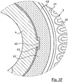
- FIG. 7 shows the filter 1 in a second embodiment, in the delivery state, in longitudinal section.
- the filter 1 also has here a cup-shaped filter housing 2 with a peripheral wall 20, with an open, here lower end face 21 and a closed, here upper end face 22, in the center of a tool attachment 23 is formed.
- a concentric with the peripheral wall 20 in the interior of the filter housing 2 projecting threaded connector 25 is firmly connected, welded here by means of a weld 25 '.
- the filter housing 2 and the threaded connector 25 are made of sheet steel, wherein the housing 2 is preferably a deep-drawn part.
- a central pipe socket 4 is further arranged in the interior of the filter housing 2, which is provided in its inner, here upper end portion 41 with an external thread 41 ', by means of which the pipe socket 4 is screwed into the threaded connector 25.
- each stop 43 is here formed by an integrally pressed out of the material of the pipe socket 4 stop tongue 43.2 with a radially outwardly facing stop tab 43.3.
- the filter element 3 consists of a hollow cylindrical filter material body 30, the front side of a lower end plate 31 and an upper end plate 32 is bordered. Each end plate 31, 32 each has a central opening 31 ', 32', each with an associated sealing lip 35, 36. Radially inside of the filter material body 30, a grid-shaped supporting body 37 is arranged.
- a sealing ring carrier 34 integrally connected, which carries a circumferential sealing ring 39.
- the sealing ring 39 protrudes in the axial direction outwards, down here, over the lower end face 21 of the filter housing 2 and seals in the assembled state of the filter 1 from this at an associated connection flange.
- the filter 1 comprises after FIG. 7 nor a filter bypass valve 5, which is arranged here in the lower region of the filter housing 2 at the level of the lower end plate 31 of the filter element 3 on the pipe socket 4.
- a valve seat 50 is formed by a ring body which is arranged tightly on the pipe socket 4 and has passage openings 50 'which extend adjacent to one another in the circumferential direction and extend in the axial direction.
- the valve seat 50 is fixed in the axial direction and the circumferential direction. With the valve seat 50 cooperates in the axial direction on the pipe socket 4, annular valve body 51 which is biased by a spring 52 in the form of a helical compression spring in the closing direction of the filter bypass valve 5.
- FIG. 7 the filter bypass valve 5 is shown in its closed position.
- the valve body 51 is sealingly against the valve seat 50 and closes the passage openings 50 'present therein.
- downwardly facing side of the filter 1 forms a connecting flange 10 for connecting the filter 1 with an associated connection flange.
- an inlet 11 for liquid to be cleaned extends into the interior of the filter 1 on its raw side 13.
- a clean region 14 of the filter Radially inwardly of the filter cloth body 30 is a clean region 14 of the filter, which over the Breakthroughs 42 is connected to the interior of the pipe socket 4, which forms a downwardly leading outlet 12 for filtered liquid.
- the filter 1 as a prefabricated unit z. B. be supplied to a motor or vehicle manufacturer, who can then install the filter 1 quickly and easily.
- a hanging arrangement is preferred for this filter design, in which the filter bypass valve 5 is then up in the filter 1 in its cleanest area.
- this filter 1 can be used in any spatial position.
- FIG. 8 shows the filter 1 off FIG. 7 in the installed state, with closed filter bypass valve 5, in longitudinal section.
- a device 6 such as the crankcase 6 of an internal combustion engine, shown, which on the upper side has a connecting flange 60, to which the filter 1 is mounted with its connecting flange 10.
- the filter 1 is screwed by means of an attached to the tool attachment 23 screwing with the threaded 40 'provided lower end portion 40 of the pipe socket 4 in a mating thread 61' of the connection flange 60 until the lower end 21 of the filter housing 2 on the surface of the connecting flange 60 is applied or a predetermined tightening torque is reached.
- liquid to be purified such as lubricating oil
- a raw liquid channel 62 in the device 6 flows through a raw liquid channel 62 in the device 6 to the inlet 11 of the filter 1 and on its raw side 13.
- the liquid then flows through the filter material body 30 of the filter insert 3 in the radial direction from outside to inside and passes, leaving behind dirt particles in the filter material body 30 on the clean side 14 of the filter 1.
- the purified liquid flows down and through the outlet 12 in the clean liquid channel 61 of the device. 6
- the filter corresponds to 1 in FIG. 8 the filter 1 in FIG. 7 , whose description is referenced.
- FIG. 9 shows the filter 1 off FIG. 8 without the filter element 3, in longitudinal section.
- the spring 52 is supported with its end remote from the valve body 51 at the stop 43, specifically the stop lugs 43.3. This ensures that the spring 52 and the valve body 51 are held captive on the central pipe socket 4, if no filter element 3 is present.
- the filter housing 2 removed, here unscrewed from the central pipe socket 4.
- the pipe socket 4 thus remains connected to the connection flange 60.
- the greater Losduswiderstand the screw between the pipe socket 4 and the flange 60 can be achieved, for example be that this screw is provided with a microencapsulated screw lock, which unfolds their securing effect when first screwing.
- a filter insert 3 can be plugged onto the pipe socket 4 from above and then the filter housing 2 can be screwed on again.
- the spring support 53 occurs on the support body 37 of the filter element 3 (see FIG. 8 ) in engagement with the upper, remote from the valve body 51 end of the spring 52 and biases them in the further movement down to a desired level.
- the filter cartridge 3 ensures the setting of a desired bias of the spring 52 and thus for a desired opening pressure of the filter bypass valve fifth
- FIG. 11 shows the filter element 3 of the filter 1 after FIG. 7 and 8th as a single part in longitudinal section.
- the hollow cylindrical filter material body 30 is sealed at its two end faces of the end plates 31 and 32 tight.
- the lower end plate 31 has the central opening 31 'with the circumferential sealing lip 35.
- the upper end plate 32 has a central opening 32 ', which is surrounded by the sealing lip 36.
- the grid-shaped support body 37 is arranged, which has a plurality of axial struts 38 spaced from each other in the circumferential direction. Its lower end forms here the spring support 53 for the spring 52 of the filter bypass valve. 5
- a spent filter cartridge 3 is exchanged for a fresh filter cartridge 3; all other parts of the filter 1 will continue to be used.
- the filter element 3 expediently consists entirely of combustible materials, so that spent filter inserts can be used without problems and completely thermally.
- FIG. 12 shows the filter housing 2 of the filter 1 from the FIGS. 7 to 9 as a single part in longitudinal section. Radially outside the rotationally symmetrical, hollow cylindrical peripheral wall 20. Below is the open end side 21. Above is the closed end 22 with the tool attachment 23 concentric to the peripheral wall 20 is in the interior of the filter housing 2 by means of the weld 25 'with the rest of the filter housing. 2 firmly connected threaded connector 25 is arranged.
- FIG. 13 shows the filter 1 off FIG. 8 , now in an operating state with open filter bypass valve 5, in longitudinal section.
- This operating state occurs when a pressure difference between the raw side 13 and the clean side 14 of the filter 1 exceeds a predefinable limit, for example as a result of high viscosity of the liquid at low temperature and / or at a filter body added by dirt particles 30.
- a predefinable limit for example as a result of high viscosity of the liquid at low temperature and / or at a filter body added by dirt particles 30.
- the force exerted by the liquid on the valve body 51 in the opening direction exceeds the force exerted by the spring 52 on the valve body 51 in the closing direction.
- the force of the liquid ensures that the valve body 51 is displaced in the axial direction on the outer circumference of the pipe socket 4 against the force of the spring 52 and lifted off the valve seat 50.
- FIG. 14 shows the filter 1 off FIG. 7 in cross-section according to the section line XIV-XIV in FIG. 7 , Radially outside the peripheral wall 20 of the filter housing 2 is visible. Radially inwardly adjoins the sealing ring carrier 34, which is connected via several, here nine, circumferentially spaced connecting webs 33 with the lower, lying in the background end plate 31 of the filter element 3. Further radially inward follows the hollow cylindrical filter material body 30, which is formed by a pleated filter web. Radially inside of the filter material body 30 is the support body 37 with the spring support 53 formed thereon. The radially innermost part forms the central pipe socket 4 with its integrally formed, radially outwardly projecting stop 43.
- FIG. 15 shows a valve seat 50 of the filter 1 after the FIGS. 7 to 14 in a first embodiment in plan view.
- the valve seat 50 has the shape of a ring body.
- Radial inside the valve seat 50 is a here only one thread comprehensive internal thread 56 can be seen, which serves to screw the valve seat 50 on the thread 40 'at the outer end portion 40 of the central pipe socket 4, as for example in the FIGS. 7 to 10 and 13 is shown.
- FIG. 16 shows the valve seat 50 of the filter 1 after the FIGS. 7 to 14 in a second embodiment in plan view.
- the valve seat 50 has the shape of an annular body, but here the passage openings 50 'in the form of mutually closely adjacent circular openings. Radially inside the internal thread 56 is also provided here.
- FIG. 17 the drawing shows the filter 1 in a third embodiment, in the installed state with closed filter bypass valve 5 and in addition with a Losdusschschschschgepuruse 47, in longitudinal section.
- the support body 37 is not or only very limited in the circumferential direction rotatable relative to the central pipe socket 4, but designed to be displaceable in the axial direction. Since, as well as in the embodiments described above, here formed on the support body 37 spring support 53, the spring 52 of the filter bypass valve 5 is supported at its end remote from the valve body 51, the spring 53 exerts an axial direction on the axially movable support body 37 in the direction of Threaded connector 25 acting force. As a result, an upper end face of the support body 37 and a lower end face of the threaded neck 25 are pressed against each other with a force determined by the spring force of the spring 52.
- the support body 37 and the threaded connector 25 are formed at their mutually contacting surfaces with interlocking contours, as will be explained later. These contours provide for the desired assurance of designed as a screw housing filter housing 2 against unwanted automatic loosening of the central pipe socket. 4
- the filter 1 has the central pipe socket 4 in its central region at its periphery the stopper 43 which is formed here in the form of integrally formed with the pipe socket 4, in the radially outwardly projecting lugs.
- the filter housing 2 is formed integrally with the threaded connector 25 and an injection molded part made of plastic.
- the central pipe socket 4 here is an injection molded part made of plastic.
- a suitable plastic which has the necessary mechanical, thermal and chemical stability, is for example polyamide (PA), which may contain a certain amount of glass fibers.
- this embodiment of the filter 1 is after FIG. 17 equipped with a filter bypass valve 5.
- the valve seat 50 is screwed with its passage openings 50 'here on the external thread 40' of the lower end portion 40 of the pipe socket 4.
- the valve body 51 is located above the valve seat 50 and is also displaceable in the axial direction on the outer circumference of the pipe socket 4 here.
- the spring 52 acts on the valve body 51 with a force acting in the closing direction.
- FIG. 17 Regarding the other parts in FIG. 17 and its function is based on the preceding description, in particular the FIG. 8 , referenced.
- FIG. 18 shows the filter 1 off FIG. 17 in cross-section along the section line BB in FIG. 17 , Radially outside the filter housing 2 with its peripheral wall 20 is visible. Radially inside of it lies in the background, the lower end plate 31 with the connecting webs 33 for the sealing ring carrier 34. On the lower end plate 31 of the filter cloth body 30 is arranged in the form of the folded filter material web. Radially inside of the filter material body 30 is the lattice-shaped support body 37. The radially innermost part of the filter 1 forms here again the central pipe socket 4, distributed over the outer periphery of which a total of four projecting lugs as a stop 43 protrude.
- the FIG. 18 illustrates that the support body 37 and the stop 43 forming lugs overlap seen in the radial direction, so that a rotation of the support body 37 relative to the central pipe socket 4 is not possible or only to a very limited extent.
- FIG. 19 shows the filter 1 off FIG. 17 also in cross section, now according to the section line C - C in FIG. 17 ,
- the radially outer part of the filter 1 to filter body inclusive 30 corresponds to that of the FIG. 18 , to the description of which reference is made.
- the threaded connector 25 of the filter housing 2 is now cut near its lower end face, in which a total of eight recesses 28 in the circumferential direction are regularly spaced apart from each other as an end-face contour.
- Losdusschsrings 47 'cam 48 integrally formed, which engage with the recesses 28.
- the recesses 28 and the cams 48 together with the spring 52, the Losdusfeld 47. Since the support body 37, as described above, is biased by the spring 52 in the direction of the threaded neck 25, the recesses 28 and the cams 48 form a kind of locking engagement, which prevents unwanted automatic rotation of the filter housing 2 against the support body 37. Since the support body 37 in turn is secured against rotation relative to the pipe socket 4, the filter housing 2 can not automatically unscrew from the central pipe socket 4 even when occurring during operation of the filter 1 in practice vibrations or pressure pulsations.
- FIG. 20 shows the filter 1 from the FIGS. 17 to 19 in longitudinal section along the section line DD in FIG. 19 ,
- the support body 37 of the filter element 3 is arranged axially displaceably on the outer circumference of the central pipe socket 4.
- the upwardly facing front end of the support body 37 and the downwardly facing end face of the threaded neck 25 together form the above-described anti-rotation lock 47.
- the downwardly facing front end of the support body 37 here again forms the spring support 53, which supports the end of the spring 52 facing away from the valve body 51.
- the integrally formed on the central pipe socket 4 noses of the Stop 43 ensure on the one hand for the desired rotation of the support body 37 relative to the pipe socket 4 and on the other hand form the stop for the spring 52 when no filter element 3 is in the filter 1.
- FIG. 21 shows the filter 1 from the FIGS. 17 to 20 in longitudinal section along the section line EE in FIG. 20 , wherein in particular the anti-rotation lock 47 is illustrated here.
- the threaded connector 25 is cut in its edge region.
- one of the recesses 28 can be seen here.
- the recess 28 engages one of the cam 48, which is on the upper end face of the support body 37, here in continuation of one of the axial struts 38, integrally formed.
- FIG. 22 shows the filter 1 from the FIGS. 17 to 21 again in longitudinal section, now according to the section line FF in FIG. 20 ,
- the central pipe socket 4 the support body 37, the valve seat 50, the valve body 51 and the spring 52 are visible in side view.
- the spring 52 acts with its lower end the valve body 51 with a closing direction in the direction of the filter bypass valve 5, that is, with a direction towards the valve seat 50, acting force.
- the same spring 52 acts on the supporting body 37 with a force acting upwards in the direction of the threaded neck 25.
- the upper end of the support body 37 is formed as Losdusêtsring 47 'of the anti-rotation lock 47.
- FIG. 23 shows the central pipe socket 4 as part of the filter 1 after the FIGS. 17 to 22 as an item in view at an angle from above.
- the external thread 41 ' In its upper end portion 41 of the pipe socket 4 has the external thread 41 ', in its lower end portion 40, the external thread 40' is provided.
- the openings 42 In the lying between the threads 40 ', 41' portion of the pipe socket 4, the openings 42 are mounted in this.
- the four lugs are formed as a stop 43, which project radially outward.
- a rib-shaped longitudinal guide 49 downwards, which ends at a distance from the lower thread 40 'each.
- the longitudinal guides 49 are used together with the lugs of the stop 43 of the blocking of the support body 37 against rotation relative to the pipe socket 4 when the filter element 3 is arranged on the pipe socket 4.
- the lugs of the stop 43 also support the spring 52, when the filter element 3 is removed from the filter 1, as already described above.
- FIG. 24 shows the support body 37 as part of the filter 1 after FIGS. 17 to 22 as an item in view at an angle from above.
- the support body 37 has the form of a hollow cylindrical, annular grid, which has a number of axial struts 38 and at the top below each an annular strut.
- the upper annular strut forms the Losfoxêtsring 47 'with the cam 48 of the anti-rotation lock 47.
- the support body 37 is preferably an injection molded part made of plastic.
- FIG. 25 is the filter housing 2 as part of the filter 1 after FIGS. 17 to 22 as an individual part in view obliquely from below, so in view of its open end 21, shown.
- the radially outer part of the filter housing 2 forms its peripheral wall 20.
- Inside the background is the closed end face 22, from which the threaded connector 25 protrudes into the interior of the filter housing 2.
- the observer facing the free end of the threaded neck 25 is provided with the regularly circumferentially spaced-apart recesses 28.
- FIG. 26 shows a unit from the filter housing 2 after FIG. 25 and the pipe socket 4 after FIG. 23 , in view obliquely from below.
- the pipe socket 4 is screwed with its upper end portion 41 and the external thread 41 'mounted there in the threaded connector 25.
- the openings 42, the stops 43 and the longitudinal guides 49 are visible.
- the screw thread 40 ' is mounted.
- FIG. 27 shows an enlarged detail FIG. 21 with the Losdusschsch 47 in a first embodiment.
- Top in FIG. 27 is an edge region of the threaded neck 25 with one of the recesses 28 visible in its end face.
- a part of the support body 37 with one of its axial struts 38 and one of the cams 48 can be seen.
- the recess 28 and the cam 48 are engaged with each other here to form the Losdusêt 47 in this way.
- the axially movable support body 37 is acted upon by the not visible here spring 52 with a pointing in the direction of the threaded connector 25 force.
- the recess 28 has here in both directions, that is in FIG. 27 to the left and to the right, symmetrical slopes, each with the same slope or the same slope.
- FIG. 28 shows the detail FIG. 21 with the anti-rotation lock 47 in a second embodiment, for which it is characteristic that the recess 28 in the end face of the threaded neck 25 in the direction of rotation, that is in FIG. 28 to the left and right, two different gradients or slopes, that is unbalanced. To the right is in FIG. 28 the slope of the recess 28 stronger than to the left.
- different rotational resistances are effected depending on the direction of rotation of the filter housing 2 relative to the support body 37, expedient such that in the fixed direction of rotation, a lower resistance and in Losdusraum a greater resistance of the anti-rotation lock 47 is generated.
- FIG. 29 the drawing shows the filter 1 in the installed state with closed filter bypass valve 5, in longitudinal section, wherein in the left and right half of FIG. 29 two different versions of a to the filter 1 after FIG. 29 matching filter cartridge 3 are shown.
- the support body 37 of the filter element 3 is arranged here in both embodiments as a separate item on the inner circumference of the filter material body 30 and is supported with its upper end against the underside of the upper end plate 32 from.
- the lower end of the support body 37 forms, as already described above, the spring support 53 for the spring 52 of the filter bypass valve fifth
- the two filter cartridges 3 in FIG. 29 differ by the position of each formed thereon spring support 53; the spring 52 is the same in both halves of the figure.
- the spring support 53 is located at a greater axial distance from the valve body 51, while in the right half of the FIG. 29 shown filter element 3 whose spring support 53 is disposed at a smaller distance to the valve body 51.
- the filter cartridge 3 in the left half of FIG. 29 thus produces a lower bias of the spring 52 than the filter element 3 in the right half of FIG. 29 , As a result, correspondingly different opening pressures of the filter bypass valve 5 are set.
- FIG. 29 Regarding the other parts in FIG. 29 and its function is based on the preceding description, in particular the FIGS. 7 and 8th , referenced.
- FIG. 30 shows the filter 1 in a relation to the FIG. 29 modified version, again in the installed state with closed filter bypass valve 5 and with a shown in the left and right half of the figure in two different versions second filter element 3, in longitudinal section.
- the support body 37 of the filter element 3 is made in one piece with the upper end plate 32, so that here the upper end plate 32 is used together with the integral support body 37 for adjusting the bias of the spring 52.
- the different bias of the spring 52 is also effected by different axial positions of the spring support 53 on the filter element 3, as a comparison of the left and right half of FIG. 30 shows. Again, therefore, by simple replacement of the filter element 3 with different axial position of the spring support 53, the opening pressure of the filter bypass valve 5 is fixed and, if necessary, to another Value can be set without the other filter 1 changes must be made.
- FIG. 31 shows the filter 1 in another over the FIG. 29 changed version, again in the installed state with closed filter bypass valve 5 and with a in the left and right half of the figure in two different versions illustrated third filter element 3, in longitudinal section.
- each of the filter element 3 is designed with a spring support 53 which is integrally formed with the lower end plate 31.
- the lower end disk 31 has radially inwardly a hollow cylindrical, axially upwardly extending projection 31 ", which ends in a radially inwardly directed, forming the spring support 53.
- FIG. 32 shows in longitudinal section a valve body 51 in a comparison with the examples described above modified version.
- Characteristic of this valve body 51 is that its end face cooperating with the valve seat 50 is provided with an elastomer support 57 in order to improve the sealing effect in cooperation with the valve seat 50.
- FIG. 33 shows a valve seat 50 in a modified version compared to the examples described above in longitudinal section.
- Characteristic of this embodiment of the valve seat 50 is that its cooperating with the valve body 51 end face is provided with an elastomeric pad 57, which also serves to improve the sealing effect in cooperation with the valve body 51.
- one of the passage openings 50 ' is visible, through which the liquid flow extends when the filter bypass valve 5 is open.
- a thread comprehensive internal thread 56 is visible, with the Valve seat 50 can be screwed onto the thread 40 'at the outer end portion 40 of the central pipe socket 4.
- both the valve seat 50 and the valve body 51 may be provided with the elastomer pad 57; Alternatively, it may also be sufficient to equip only the valve seat 50 or only the valve body 51 with the elastomer support 57.
- this is a screw-on filter element with replaceable filter element 3, which can be attached to the connecting flange 60 of the associated device 6, such as the internal combustion engine, instead of a merely replaceable screw-on filter cartridge.
- the FIG. 34 shows in contrast to a filter 1 in an angled longitudinal section, which has its own base 6 ', with which it is connectable to an associated device 6, such as internal combustion engine, or with a functional module forming part of the device.
- the filter 1 is after FIG. 34 to a so-called hanging filter 1, in which a releasable part of the filter housing 2 forming screw 20 'can be unscrewed and disassembled downwards. Accordingly, here the filter element 3 is also installed from below and removed downwards.
- the non-detachable part of the filter housing 2 is made here with the base 6 'in one piece and, for example, a die-cast part made of light metal, such as aluminum.
- the screw cap 20 ' may also be a die cast part made of light metal or alternatively also an injection molded part made of plastic.
- a sealing ring 39 By means of a sealing ring 39, the screw cap 20 'is sealed in its screwed-in state against the rest of the filter housing 2 liquid-tight.
- a tool attachment 23 for example, a hexagon.
- a conventional and per se known screw valve is arranged here as a drain valve in order to be able to empty the interior of the filter 1 clean of liquid before opening the filter housing 2.
- a filter insert 3 is also arranged here, which consists of a hollow cylindrical filter material body 30, which is sealed at its two end faces of end plates 31 and 32. Inside the filter cloth body 30 is also a grid-shaped, arranged in its basic form hollow cylindrical support body 37. As is well known, here the filter cartridge 3 is releasably locked by means of arranged on its lower end plate 31 locking arms with the screw 20 '.
- a central pipe socket 4 is arranged in the interior of the filter housing 2, which has in the upper end portion 40 outside a screw thread 40 ', with which it is screwed into a mating thread 61' in the base 6 '. With his in FIG. 34 upper, a central opening having end plate 32 of the filter element 3 is attached from below to the central pipe socket 4.
- a filter bypass valve 5 is arranged at the level of the upper end plate 32.
- an annular valve seat 50 is mounted directly above the upper end plate 32 in the axial direction immovably on the outer circumference of the pipe socket 4, screwed here. Through the valve seat 50 pass through openings 50 'in its axial direction.
- a valve body 51 is displaceably guided in the axial direction on the outer circumference of the pipe socket 4. Seen in longitudinal section, the valve body 51 has the shape of an upside down L, wherein a longer L-leg forms the guide on the pipe socket 4 and a shorter L-leg projects radially outward. An upper end side of the shorter L-leg cooperates with a lower end face of the valve seat 50; a lower end face of the shorter L-leg forms a contact surface for a spring 52, which acts on the valve body 51 in the closing direction with a biasing force.
- the remote from the valve body 51, lower end of the spring 52 is here at a left in FIG. 34 visible, cut spring support 53 is supported, which is an integral and integral part of the support body 37 within the filter cartridge 3.
- a liquid to be cleaned such as lubricating oil of an internal combustion engine, flows through a raw liquid channel 62 in the base 6 'to the inlet 11 of the filter 1 and on its raw side 13.
- the liquid reaches the clean side 14, leaving behind dirt particles of the filter 1 and through the support body 37 into the central pipe socket 4 and through this to the outlet 12, which in turn merges into a clean fluid channel 61 in the base 6 '.
- the filter bypass valve 5 remains closed. If the pressure difference exceeds the predeterminable limit value, the force of the liquid acting on the valve body 51 through the passage openings 50 opens the filter bypass valve 5 and a flow path from the raw side 13 through the passage openings 50 'and the openings 42 in the pipe socket 4 directly to the clean side 14 bypassed the Filterstoff emotionss 30 released.
- valve body 51 is displaced against the force of the spring 52 on the outer circumference of the central pipe socket 4 in its axial direction.
- tilt-free guidance of the valve body 51 on the central pipe socket 4 should expediently be the axial length of the valve body 51 at least as large as its inner diameter.
- the filter 1 is operable in any spatial position;
- the filter 1 instead of as a hanging filter, as in FIG. 34 , can also be used as a horizontal or vertical filter or in any intermediate or inclined position.
- the filter bypass valve 5 is expediently arranged in a position which is as high as possible during operation in order to minimize contamination of valve seat 50 and valve body 51 due to settling dirt particles from the liquid.
- FIG. 35 the drawing shows the filter 1 FIG. 17 in a modified embodiment, namely with an anti-rotation device for the valve body 51 of the filter bypass valve 5, in longitudinal section.
- this embodiment of the filter 1 is after FIG. 35 equipped with a filter bypass valve 5.
- the valve seat 50 is screwed with its passage openings 50 'here on the outer screw 40' of the lower end portion 40 of the pipe socket 4.
- the valve body 51 is located above the valve seat 50 and is also displaceable in the axial direction on the outer circumference of the pipe socket 4 here.
- the spring 52 acts on the valve body 51 with a force acting in the closing direction.
- valve body 51 secured against rotation relative to the pipe socket 4 and relative to the valve seat 50.
- longitudinal rib 45 for example integrally formed. Matching this is formed on the inner circumference of the valve body 50 extending in the axial direction of a longitudinal groove 55 which receives the longitudinal rib 45 with a necessary movement play.
- the longitudinal rib 45 and the longitudinal groove 55 form a valve body guide, which allows axial displacement of the valve body 51 on the pipe socket 4 and at the same time a lock against rotation of the valve body 51 in the circumferential direction relative to the pipe socket 4 and relative to the valve seat 50 forms. In this way, in the course of the period of use of the filter 1, possibly resulting from a relative rotation of the valve body 51 and valve seat 50 leaks of the filter bypass valve 5 in its closed position can be safely avoided.
- FIG. 35 Regarding the other parts in FIG. 35 and its function is based on the preceding description, in particular the FIGS. 8 and 17 , referenced.
- FIG. 36 shows the filter 1 off FIG. 35 in cross section according to the section line HH in FIG. 35 , Radially outside the filter housing 2 with its peripheral wall 20 is visible. Radially inside of it lies in the background, the lower end plate 31 with the sealing ring carrier 34. On the lower end plate 31 of the filter cloth body 30 is arranged in the form of the folded filter material web. Radially inside of the filter material body 30 is here the annular valve body 51. Between the inner periphery of the lower end plate 31 and the outer circumference of the valve body 51 is still a small, radially outer part of the valve body 51 concealed by the valve body 51 valve seat 50 can still be seen.
- the radially innermost part of the filter 1 again forms the central pipe socket 4 with the openings 42, two of which are visible here in section.
- the longitudinally rib 45 projecting in the axial direction of the pipe socket 4, which projects in the radial direction, can be seen on its side pointing to the right.
- the longitudinal groove 55 is formed on the inner circumference of the annular valve body 51, which receives the longitudinal rib 45.
- FIG. 36 illustrates that a rotation of the valve body 51 relative to the central pipe socket 4 and relative to the non-rotatably mounted on the pipe socket 4 valve seat 50 is not possible.
- FIG. 37 shows that in FIG. 36 circled detail in an enlarged view.
- Left in FIG. 37 is a part of the central pipe socket 4 visible with its lying on the outer circumference longitudinal rib 45.
- Radially outwards, that is, to the right here, follows the valve body 51 with the longitudinal rib 55 receiving longitudinal groove 55 in its inner circumference.
- the longitudinal rib 45 and the longitudinal groove 55 have sufficient freedom of movement relative to each other.
- valve body 51 Radially outside of the valve body 51 is still a small part of the lower end plate 31 with the filter material body 30 can be seen.
- FIG 38 shows the filter 1 in a further embodiment, in longitudinal section, in a state attached to a connection flange 60 of a device 6.
- the filter 1 again has a cup-shaped filter housing 2, which is open at its flange-side end 21.
- a central pipe socket 4 is arranged, which consists of a first, flange-side pipe socket section 4.1 and a close to the flange end face 22 of the filter housing 2 second, second flange section 4.2, wherein the two pipe socket sections 4.1 and 4.2 are screwed together.
- the parts of the filter bypass valve 5 are arranged, namely below the first valve seat 50, above the axially displaceable valve body 51 and above the spring 52, which preloads the valve body 51 in the closing direction of the filter bypass valve 5.
- the spring 52 in Figure 38 shown in the ready state supported by the spring support 53 and biased.
- the spring support 53 is also part of the filter element 3, more precisely of the central support body 37th
- a stop 43 is arranged, to which the upper end of the spring 52 applies when the filter housing 2 and with this together the filter element 3 are separated from the rest of the filter 1. The spring 52 and the valve body 51 are thus secured against losing.
- the stop 43 is designed with roof-shaped insertion bevels 46, via which the support arms 53 'are guided during assembly of the filter 1.
- the filter 1 has after Figure 38 Also, a return check valve 15 which covers the inlet 11 and prevents idling of the filter 1 at standstill of the liquid circuit.
- FIG. 39 shows the filter 1 off Figure 38 in cross-section along the section line G - G in Figure 38 , Radially outward extends the peripheral wall 20 of the filter housing 2. Radially inwardly of the return check valve 15 is visible with the spring tongue plate 18. Next, the sealing ring 39 'continues radially inward, followed by the valve seat 50. Still further radially inward, the flange-side pipe socket section 4.1 is cut, onto which the threaded nipple 63 of the associated connecting flange 60 still further radially inwardly follows. In the center of FIG. 39 is the outlet 12 of the filter. 1
- FIG. 40 shows the filter 1 off Figure 38 in cross-section along the section line H - H in Figure 38 ,
- the peripheral wall 20 of the filter housing 2 is initially cut radially outward.
- Radially inwardly of the filter material body 30 of the filter element 3 is located with the central support body 37.
- the spring supports 53 are integrally formed on the support body 37 and project radially inwardly. Radially inside of the support body 37 then follow the stop 43 and the pipe socket sections 4.1 and 4.2.
- FIG. 41 shows the filter housing 2 and the filter insert 3 of the filter 1 arranged therein Figure 38 in longitudinal section, which together form the structural unit which is degraded during maintenance of the filter 1.
- the flange-distant pipe socket section 4.2 with its lower external thread 41 "unscrewed from the flange-side pipe socket section 4.1, wherein the filter element 3 is taken due to its friction to the filter housing 2. If the filter housing 2 is completely unscrewed, the filter element 3 by the open bottom of the filter housing 2 pulled out of this and replaced by a fresh filter element 3 including the support body 37 with the spring support 53.
- the seal 39 is here also part of the filter cartridge 3 and is supported by a sealing ring carrier 34 which is connected via connecting webs 33 with the lower, flange-side end plate 31 of the filter element 3 or made in one piece.
- Figure 42 shows the filter housing 2 with the filter element 3 from FIG. 41 in view diagonally from below.
- the filter element 3 are here the lower, flange-side end plate 31, the connecting webs 33, the sealing ring carrier 34 and the radially outer sealing ring 39 visible.
- the central opening 31 'of the end disk 31 runs around the radially inner sealing ring 39'. Through the opening 31 'through a part of the inner support body 37 of the filter element 3 is visible.
- FIG. 43 shows the filter element 3 of the Filter1 Figure 38 in view diagonally from below.
- the essential part of the filter element 3 forms its hollow cylindrical filter material body 30, which is covered on the underside of the end plate 31 and the top side of the end plate 32. From the radially outer edge of the lower end plate 31 go several, here five, evenly distributed over the circumference connecting webs 33 in the axial direction downwards out, carrying the sealing ring carrier 34, on the outside of the outer sealing ring 39 is arranged.
- Around the central opening 31 'of the lower end plate 31 around is again the radially inner seal 39' visible. Through the opening 31 'through a small part of the grid-shaped inner support body 37 is visible.
- FIG. 44 shows the filter cartridge 3 off FIG. 43 in an angled longitudinal section.
- the spring supports 53 which are arranged distributed over the inner circumference of the support body 37.
- the radially inner sealing ring 39' is arranged on the outer circumference of the sealing ring carrier 34.
- FIG. 45 shows the filter cartridge 3 off FIG. 44 in cross-section after the section line F '- F' in FIG. 44 , Radially outside, the sealing ring 39 is visible, which is supported by the radially inwardly extending therefrom sealing ring carrier 34. From the sealing ring carrier 34, the connecting webs 33 go upwards from. Further radially inward, the second sealing ring 39 'is cut.
- FIG. 46 shows the filter housing 2 of the filter 1 from Figure 38 in view diagonally from below.
- the filter housing 2 extends concentrically to the peripheral wall 20 of the flange distant pipe socket section 4.2 with its thread 41 "for connection to the second, flange side pipe section 4.1, which remains after an initial installation of the filter 1 at the connection flange 60 when the filter housing 2 is unscrewed, as on In the pipe socket section 4.2, one of the apertures 42 provided therein is visible, through which filtered liquid passes into the interior of the central pipe socket 4 during operation of the filter 1.
- FIG. 47 shows a connecting flange 60 of the filter 1 with the remaining after removal of the filter housing 2 and filter cartridge 3 filter parts.
- the filter parts remaining on the connecting flange 60 are the flange-side pipe socket section 4.1 with the filter bypass valve 5 arranged thereon and the return-blocking valve 15 also arranged thereon.
- FIG. 47 At the top of FIG. 47 is the arranged at the upper end of the pipe socket section 4.1 stop 43 with the top-side chamfers 46 visible and inside the upper end of the pipe socket section 4.1 whose internal thread 40 "visible, with which the thread 41" of the non-existing flange remote pipe socket section 4.2 is screwed. Under the stop 43, the spring 52 of the filter bypass valve 5 is visible, which pre-loads the valve body 51 in the closing direction and presses against the valve seat 50.
- the return check valve 15 comprises an annular flexible valve diaphragm 15 'and a spring tongue disc 18 arranged above it, which is connected to the outer circumference of the valve seat 50 via a plurality of latching connections 17 arranged distributed in the circumferential direction.
- a plurality of latching connections 17 arranged distributed in the circumferential direction.
- FIG. 48 shows the subject of the FIG. 47 in longitudinal section, in which case it is particularly clear that the flange-side pipe socket section 4.1 is screwed with the screw thread 40 'mounted in its outer, ie lower end region 40 on a threaded nipple 63 arranged centrally in the connection flange 60 with a mating thread 61'.
- the threaded nipple 63 in turn is permanently screwed in the center of the connecting flange 60 via a further screw with the device 6.
- the screwing of the pipe socket section 4.1 with the threaded nipple 63 takes place during an initial assembly of the filter 1 and is secured by a Losdusêt 67 against loosening when in FIG. 48 not shown filter housing 2 is unscrewed together with the flange-distant pipe socket section 4.2 from the flange-side pipe socket section 4.1.
- the parts of the filter bypass valve 5 are provided in the arrangement already described above.
- the stop 43 sits with the top insertion chamfers 46, which in assembling the filter 1, the arranged in the filter element 3 spring supports 53 and support arms 53 'in spaces 44 at the lower end of the insertion 46 lead.
- the filter cartridge 3 can be used, which has the spring supports 53 and support arms 53 'in the number 44 corresponding to the spaces 44, shape and distribution.
- the return valve 15 covering the inlet 11 is arranged, which here has its own membrane carrier 15 ".
- FIG. 49 shows the detail Y FIG. 39 in an enlarged view.
- a small part of the threaded nipple 63 is visible, which is surrounded radially outward, that is to the right, by the flange-side pipe socket section 4.1.
- the valve seat 50 Next to the outside, that is, to the right, follow the valve seat 50 and the radially inner sealing ring 39 '.
- Right, that is radially outward of this, is still a part of the return check valve 15 with the spring tongue plate 18 can be seen.
- the parts of the return check valve 15 are connected via the latching connections 17 with the valve seat 50, wherein FIG. 49 a latching connections 17 shows. Further clarifies the FIG.
- sealing ring 39 ' is adapted in its course to the arrangement and position of the snap-in connections 17 and here in each case deflects radially outwards. This adapted to the location of the locking connections 17 course of the sealing ring 39 'is already in the Figures 42 . 43 and 45 visible, noticeable.
- FIG. 50 shows the detail X FIG. 40 in an enlarged view, here in the right part of the FIG. 50 the filter material body 30 is visible, which is radially inwardly, that is supported in the figure on the left, by the inner support body 37. Integral with the support body 37 is here one of the spring support 53 visible, which engages in one of the intermediate spaces 44 in the stop 43. Radially inwardly from the stop 43, that is, in this figure to the left thereof, are still small parts of the pipe socket sections 4.1 and 4.2 visible.
- FIG. 51 shows a the filter bypass valve 5 and the return check valve 15 comprehensive assembly as parts of the filter 1 from Figure 38 , in view obliquely from below.
- the stop 43 with the insertion bevels 46 and the intermediate spaces 44 between them recognizable.
- Underneath is the spring 52 of the filter bypass valve 5, which preloads its valve body 51 in the closing direction against the valve seat 50.
- FIG. 52 shows the unit FIG. 51 together with the connecting flange 60 and the filter housing 2 with filter element 3, in an exploded view obliquely from below.
- the filter housing 2 is visible with the filter insert 3 arranged therein.
- the assembly of the pipe socket section 4.1 with the filter bypass valve 5 and the return check valve 15 is visible.
- the connection flange 60 of the device 6 with the arranged in the center threaded nipple 63 with the mating thread 61 'for the not visible here, provided in the lower end of the pipe socket section 4.1 thread recognizable.
- FIG. 53 shows the detail Z FIG. 48 in an enlarged view, to illustrate the execution of the return check valve 15 used here.
- a part of the connecting flange 60 of the device 6 with the raw liquid channel 62 is visible, leading to the inlet 11 of the filter 1.
- the inlet 11 is here embodied in the form of a plurality of openings distributed in the circumferential direction in the membrane carrier 15 "on the upper side of the membrane carrier 15" is the flexible valve diaphragm 15 ', which is occupied on the upper side with the spring tongue plate 18, which has a restoring force acting in the closing direction on the Valve membrane 15 'exerts.
- the unit of membrane carrier 15 ", valve diaphragm 15 'and spring tongue plate 18 is connected by means of the locking connections 17 already mentioned above with the valve seat 50 of the filter bypass valve 5.
- FIG. 54 shows the detail W Figure 38 In an enlarged view, now in a state with built-filter cartridge 3 and attached filter housing 2.
- the filter housing 2 is sealed liquid-tight by the radially outer sealing ring 39 which lies between the filter housing 2 and the connecting flange 60.
- FIG. 55 shows the filter element 3 of the filter 1 in a modified version for a filter 1 without return check valve 15, in view obliquely from below.
- the filter cartridge 3 according to FIG. 55 the radially inner sealing ring 39 'running circular, since he does not need the special shape to take into account the position of the locking connections 17 here.
- the filter cartridge 3 corresponds to FIG. 55 the embodiment explained above.
- FIG. 56 shows the filter cartridge 3 off FIG. 55 in longitudinal section, whereby here also the continuous circular course of the radially inner sealing ring 39 'is visible.
- Figure 57 shows the filter 1 in a further embodiment in longitudinal section, for this embodiment, in contrast to the example according to Figure 38 Characteristic is that no return check valve 15 is present.
- the liquid to be filtered from the Roh alloykeitskanal 62 on the raw side 13 of the filter 1 leading inlet 11 is here permanently open.
- the filter 1 corresponds to the basis of Figure 38 described embodiment.
- the filter 1 after Figure 57 is particularly suitable for applications in which it is not disturbing if the liquid flows out of the filter 1 when the liquid circuit is at a standstill.
- FIG. 58 shows a unit with the filter bypass valve 5 as part of the filter 1 from Figure 57 , in view.
- the filter bypass valve 5 is carried here again by the flange-side pipe socket section 4.1, on the outer circumference from bottom to top of the valve seat 50, the valve body 51, the spring 52 and the stop 43 are arranged with the insertion bevels 46 and the intervening spaces 44.
- the screw 40 ' is attached inside the lower end of the pipe socket section 4.1.
- the Loscordêt 67 is visible. Because of the absence of the return check valve in FIG. 58 compared to FIG. 51 no membrane carrier with the other parts of the return valve.
- FIG. 59 shows the unit FIG. 58 in a state mounted on a connection flange 60, viewed obliquely from above.
- the visible here state results when the filter housing 2 is removed together with the filter cartridge 3 for filter maintenance from the connection flange 60.
- the two pipe socket sections 4.1 and 4.2 separate from each other, since due to the Losdusêt 67 of the flange-side pipe socket section 4.1 is secured against unscrewing from the connection flange 60.
- To the Losdusêt 67 runs around the annular Rohenbergkeitskanal 62, which leads to the inlet 11 of the filter 1.
- the clean liquid channel 61 is visible, is discharged through the filtered liquid during operation of the filter 1.
- the connecting flange 60 is formed on a base 6 'which can be connected via further lines to the rest of the device 6, which has the fluid circuit with the filter 1.
- FIG. 60 shows the filter housing 2 with arranged therein filter element 3 of the filter 1 Figure 57 , in view obliquely from below.
- Radially inwardly from the downwardly facing open end 21 of the peripheral wall 20 of the filter housing 2 extends the sealing ring 39, which is supported by the sealing ring carrier 34.
- the sealing ring carrier 34 is connected by means of the connecting webs 33 with the lower end plate 31 of the filter cartridge 3.
- Around the central opening 31 'in the lower end disk 31 around the annular extending inner sealing ring 39' is arranged. Through the opening 31 'through a part of the inner support body 37 is visible with a short portion of one of the spring supports 53.
- Radially outside of the support body 37 is the filter material body 30th
- FIG. 61 shows the filter housing 2 with filter element 3 from FIG. 60 in longitudinal section.
- the filter housing 2 and the pipe socket section 4.2 are expediently welded together in the region in which they rest against one another.
- the thread 41 "visible that serves to screw with the flange-side pipe socket section 4.1.
- the peripheral wall 20 has an inner diameter step 24, on which the lower end plate 31 abuts with its upper side, whereby the filter element 3 relative to the filter housing 2 in the axial direction receives a defined position.
- the filter element 3 is centered by the existing on the lower end plate 31 connecting webs on the one hand and by the seal 36 on the inner circumference of the upper end plate 32 on the other hand in the radial direction relative to the filter housing 2.
- the radially outer sealing ring 39 is supported on an axially downwardly facing circumferential surface of the peripheral wall 20 from. To the central aperture 31 'in the lower end plate 31 around the radially inner sealing ring 39' extends.
- the grid-shaped supporting body 37 is arranged, with which here the spring supports 53 are designed as radially inwardly projecting ribs in one piece. Due to an angled course of the cut, only one of the spring supports 53 in the left half of FIG. 61 visible, noticeable.
- the support body 37 is here connected to both the lower end plate 31 and the upper end plate 32, for example glued or welded.
- FIG. 62 shows the unit FIG. 58 together with a connecting flange 60 and a filter housing 2 with filter element 3 arranged therein, in an exploded view.
- the filter element 3 is inserted from the open, flange-side end face 21 of the filter housing 2 ago in this and keeps in the filter housing 2 due to mutual friction or detent.
- the unit visible under it comprises the basis of FIG. 58 already explained parts, in particular the filter bypass valve 5.
- the connecting flange 60 is visible, here as part of a base 6 ', which is part of a device 6, which has a liquid circuit with liquid to be filtered. From the connection flange 60, the threaded nipple 63 projects centrally with its thread 61 '.
- FIG. 63 shows the subject of the FIG. 59 in longitudinal section.
- the threaded nipple 63 is permanently and permanently screwed to a lower threaded portion.
- the spring supports 53 do not act on the spring 52, the spring is now expanded to its maximum length and is at its upper end to the stop 43 at. Loss of the spring 52 and the valve body 51 is thus excluded.
- FIG. 64 shows the filter 1 in a further embodiment in longitudinal section. Also in this filter 1 is again a Anschraubfilter which is screwed to a connection flange 60 of a device 6 with liquid circuit.
- the connecting flange 60 here again has a central threaded nipple 63 with a thread 61 'protruding from the plane of the connecting flange 60.
- the filter 1 has a base plate 16 which has radially inside a female thread 16 'and radially outside an external thread 16 "and distributed in the area lying between the two threads 16', 16" several distributed in the circumferential direction Openings as an inlet 11 for liquid to be filtered.
- the base plate 16 is screwed to the threaded nipple 63.
- the filter housing 2 is screwed, which has the screw thread 26 inside the lower end of its peripheral wall 20 inside.
- valve holder 58 is mounted on the threaded nipple 63 above the base plate 16, on or in which the parts of the filter bypass valve 5 are arranged.
- the valve holder 58 is embodied here in two parts with a lower holder part 58.1 and an upper holder part 58.2 fixedly connected thereto.
- the valve seat 50 is formed here in a bottom of the lower holder part 58.1.
- the valve body 51 is designed as a flat annular disc and is located in his in FIG. 64 By means of the valve holder 58 arranged in the helical compression spring 52, the valve body 51 is biased with a force acting in the closing direction force.
- the spring 52 is again biased by the filter element 3 by a one-piece with the central support body 37 in the filter material body 30 spring support 53 presses with a radially inwardly and then axially downwardly facing annular support collar from above to the spring 52.
- the support body 37 is connected here only with the lower end plate 31.
- the upper end of the support body 37 is located at a distance from the underside of the upper end plate 32nd
- the filter element 3 here has a lower end plate 31 which carries on the underside a circumferential seal 35, with which the lower end plate 31 is sealingly placed on the outer circumference of the valve holder 58. From the radially outer edge of the lower end plate 31 again go down connecting webs 33 in the axial direction downwards, which carry a circumferential sealing ring carrier 34, on the outer circumference of a radially outer sealing ring 39 is arranged, which seals the filter housing 2 against the connecting flange 60.
- On the upper side of the filter cartridge 3 has a closed end plate 32nd
- FIG. 65 shows the filter 1 in a further embodiment in longitudinal section.
- the filter 1 corresponds to the example FIG. 64 .
- a cover body 59 is assigned, which ensures that in a filter maintenance with removal of the filter housing 2 and the filter element 3, the outlet 12 is closed for filtered liquid to prevent that from the filter element 3 or the filter housing 2 dirt particles in the outlet 12th and from this into the clean fluid channel 61 of the device 6 arrive.
- the covering body 59 is arranged on the upper side of the spring 52 and is biased by the spring 52 with a force pointing upwards, that is to say away from the valve body 51.
- the support body 37 is here supported with its flanschfernen, upper end face on the inside of the flange remote, upper end plate 32 of the filter element 3.
- the filter element 3 in turn is supported with its flange-distant, upper end plate 32 inside of the filter housing 2 from.
- the support body 37 is rotatably disposed inside the filter cloth body 30 relative to the rest of the filter cartridge 3.
- the support body 37 is located at its upper end, although on the underside of the upper end plate 32 of the filter element 3, but is not connected to this end plate 32. With the flange-side, lower end plate 31 of the filter element 3, the support body 37 has no direct contact here.
- FIG. 66 shows the filter 1 in a further embodiment in longitudinal section.
- the filter 1 according to FIG. 66 in most of its parts corresponds to the example FIG. 64 , Different is that in the example after FIG. 66 the inlet 11 is associated with a return check valve 15.
- the return check valve 15 is in the form of a flexible valve membrane 15 'on the top of the base plate 16 and thus covers the openings 11 forming the inlet in the base plate 16. By coming from Roh Itkeitskanal 62, to be filtered liquid, the return valve 15 is opened automatically. At standstill of the liquid circuit, the return check valve 15 ensures that the filter 1 is not empty.
- FIG. 67 shows the filter 1 in a further embodiment in a first, angled longitudinal section along the section line A - A in Figure 68 wherein the filter 1 is shown here in a mounted on a connection flange 60 of a device 6, such as internal combustion engine, state.
- a threaded nipple 63 with an external thread 61 'lying above the flange plane is part of the connecting flange 60, in which case the threaded nipple 63 is designed as a double nipple and in turn is permanently screwed into the device 6 with a lower external thread.
- the filter 1 comprises a filter housing 2, which here has the shape of a downwardly open cup.
- the housing 2 has an internal thread 26, which here is in screw engagement with the external thread 16 "of the base plate 16.
- both the base plate 16 and the housing 2 are plastic parts
- the base plate 16 and the housing 2 may be parts made of metal, in particular die-cast parts made of light metal, such as aluminum.
- a filter insert 3 is arranged, which consists of a hollow cylindrical filter material body 30 with two frontally enclosing end plates 31 and 32. By means of a central opening in the lower end disk 32, the filter element 3 is installed under sealing by a sealing collar in the filter 1.
- the connecting webs 33 merge into a circumferential sealing ring carrier 34, which has a cylindrical outer surface and on which a circumferential seal 39 in the form of an elastic, unencumbered, cross-sectionally approximately round sealing ring is arranged.
- the filter element 4 is fixed by means of its connecting webs 33 relative to the filter housing 2 in a defined, desired position.
- an axially downwardly facing support surface is formed, on which the seal 39 rests with its upper side.
- the seal 39 is compressed in the axial direction so far that it expands radially outwards and inwards and seals both axially and radially.
- a plurality of openings distributed in the circumferential direction of the base plate 16 extend as an inlet 11 for liquid to be filtered, on the top side the inlet 11 is covered with a return check valve 15.
- Central through the Base plate 16 and the threaded nipple 63 extends the outlet 12 for filtered liquid.
- a filter bypass valve 5 is centrally arranged on the upper side, which extends into the support body 37 inside.
- a part of the filter bypass valve 5 forming, in its basic form hollow cylindrical valve holder 58 is fixedly connected at its lower end to the base plate 16, for. B. friction welded.
- the valve holder 58 here consists of two parts, namely a first, lower holder part 58.1, which is fixedly connected to the base plate 16, and a second, upper holder part 58.2, which in turn is connected to the first holder part 58.1, here by a latching.
- the holder parts 58.1 and 58.2 made of plastic.
- valve seat 50 is formed at the bottom, which cooperates with an axially in the valve holder 58 outwardly guided valve body 51.
- a spring 52 which exerts a force acting in the closing direction on the valve body 51 when the filter insert 3 is installed in the filter 1.
- an axially movable cover body 59 is here in the valve holder 58 is still arranged, on the underside of the upper end of the spring 52 abuts and on its upper side, as long as the filter element 3 is installed in the filter, the spring support 53 with its support arms 53 ' is present, which hold the cover body 59 in a spaced-apart from the bottom of the upper valve holder end position.
- the cover body 59 exposes a fluid passage 58 "in an upper end wall of the filtered fluid valve holder 58 toward the outlet 12.
- the fluid passage 58" is formed by a plurality of circumferentially spaced smaller apertures, the total of which provide necessary flow cross-section available.
- the spring 52 presses the cover body 59 against and closes the end wall of the valve holder 58 and against the liquid passage 58 "there Liquid can fall.
- cover body 59 ensures a favorable distribution of the forces acting between the valve spring 52 and the spring support 53.
- the cover body 59 can also be omitted if, in the intended use of the filter 1, the protective function against dirt and the function of the distribution of forces are dispensable.
- a radially inwardly facing stop 58 ' is formed, which provides for limiting the movement of the cover body 59 and the upper end of the spring 52 upwards, that is, from the valve seat 50 away.
- the support body 37 again has the spring support 53, here in the form of a plurality of axially downwardly facing support arms 53 ', which are distributed over the inner circumference of the support body 37. Due to the angled course of the cutting plane is in FIG. 67 only one of the support arms 53 'in the left half of FIG. 67 visible, noticeable.
- valve diaphragm of the return check valve 15 is clamped at its radially inner edge region between the base plate 16 and the lower holder part 58.1 of the valve holder 58, which makes own holding means for the return check valve 15 unnecessary.
- liquid to be filtered flows through a Roh totallykeitskanal 62 in the radially outer part of the connection flange 60 and through the inlet 11 and through the return check valve 15 passes to a lying outside of the filter element 3 raw side 13 of the filter 1. From there, the liquid flows under Separation of solid particles through the FilterstoffMech 30 of the filter cartridge 3 in the radial direction inwards on the clean side 14 of the filter 1. From there, the filtered liquid succeeded through the interior of the support body 37, through the liquid passage 58 "in the valve holder 58, then through the central outlet 12 and through the interior of the threaded nipple 63 in a clean liquid channel 61 in the connection flange 60th
- valve body 51 If the pressure difference between the raw side 13 and the clean side 14 of the filter 1 exceeds a predetermined limit, the valve body 51 is lifted against the force of the valve spring 52 of its valve seat 50 and there is an immediate flow path for the liquid from the raw side 13 to the clean side 14th bypassed by the Filterstoff stressess 30 of the filter cartridge 3 released.
- the return check valve 15 ensures that no liquid flows from the interior of the filter 1, so that when the liquid cycle starts again an immediate supply of liquid secondary consumption points with filtered liquid is ensured.
- Figure 68 shows the filter 1 off FIG. 67 in cross-section along the section line B - B in FIG. 67 , Outside is in Figure 68 the filter housing 2 visible, the peripheral wall 20 is cut here. Radially inside thereof is the filter cartridge 3, through the filter material body 30 of the cut runs. Distributed over the circumference of the filter element 3, the four connecting webs 33 are visible from above, which extend further downwards in the axial direction. More radially inwardly of the valve holder 58 is arranged, in which the parts of the filter bypass valve 5 are, of which only a part of the valve spring 52 and centrally a part of the valve body 51st are visible. With the section line A - A is in Figure 68 illustrates how the in FIG. 67 shown longitudinal section through the filter 1 extends.
- Figure 69 shows the detail V of the filter 1 Figure 68 in an enlarged view.
- Top right in Figure 69 is a part of the filter material body 30 of the filter element 3 can be seen.
- a portion of the support body 37 is visible.
- the valve holder 58 consists of a first holder part 58.1 and a second holder part 58.2, which are inserted over a part of their height into one another.
- the two holder parts 58.1 and 58.2 are connected to each other by means of latching connections 58.3, of which in Figure 69 one is visible on average.
- a part of the valve body 51 is finally visible below.
- FIG. 70 shows the filter 1 off FIG. 67 in cross-section along the section line D - D in FIG. 67 , Again, the filter housing 2 is visible radially outward again, the peripheral wall 20 is cut. Radially inside of it is again the filter element 3 with the filter material body 30 and the axially downwardly extending connecting webs 33. Radially inside of the filter material body 30 is the associated support body 37. Again radially inwardly thereof, the valve holder 58 is arranged. As the FIG. 70 illustrated, the valve holder 58 has at its visible here top a number of insertion 53 "through which the support arms 53 ' the spring support 53 of the filter insert 3 protrude into the interior of the valve holder 58. In addition, besides the introduction openings 53 "in the upper side of the valve holder 58, there is a liquid passage 58" in the form of a plurality of openings distributed in the circumferential direction through which filtered liquid flows during operation of the filter 1.
- FIG. 71 shows the detail U of the filter 1 FIG. 70 in an enlarged view.
- a part of the filter cloth body 30 can be seen.
- the insertion openings 53 'and the support arms 53' form a key-lock coding, which only allows the incorporation of a certain, the support arms 53 'in a suitable arrangement, number and shape having filter cartridge 3 in the filter 1.
- FIG. 72 shows the filter 1 off FIG. 67 in a second, opposite FIG. 67 twisted longitudinal section along the section line C - C in Figure 68 .
- the valve body 51, the valve spring 52 and the cover body 59 can be seen here.
- the support arms 53 'of the spring support 53 of the filter element 3 are in abutment against the upper side of the cover body 59 and press on this spring 52 together.
- the spring 52 exerts a predeterminable force acting in the closing direction on the valve body 51 of the filter bypass valve 5.
- an opening of the liquid passage 58 is visible, through which liquid filtered during operation of the filter 1 flows.
- FIG. 73 shows the detail X of the filter 1 FIG. 72 in an enlarged view.
- the valve seat 50 is visible, which is formed as part of the first holder part 58.1.
- valve body 51 which on its the valve seat 50 facing surface an elastomeric pad 57 to improve the sealing effect in the closed position wearing.
- Around an upper part of the valve body 51 around the spring 52 extends in the form of a helical compression spring.
- Radially outward, that is here right of the first holder part 58.1 is a part of the second holder part 58.2 recognizable, wherein the holder parts 58.1 and 58.2 by means of the latching connections 58.3, of which in FIG. 73 one is visible, interconnected.
- valve body 53 Radially outside of the valve body 53, that is in FIG. 73 right, a small part of the filter element 3 with the filter material body 30, the lower end plate 31, the sealing collar 35 and the grid-shaped support body 37 is visible. Centrally located in the lower end disc 31 is the opening 31 ', by means of which the filter insert 3 is sealingly placed on the second holder part 58.2 of the valve holder 58.
- Figure 74 shows the filter 1 off FIG. 72 in cross-section along the section line I - I in FIG. 72 , Radially outside is the filter housing 2 of the filter 1, wherein the peripheral wall 20 of the housing 3 is cut here again. Further radially inward, the filter insert 3 is visible with the here cut filter cloth body 30, which is supported radially inwardly by the support body 37. Radial inside of the support body 37, the valve holder 58 is visible, in which the cover body 59 is located. Right in the center of the Figure 74 Finally, the valve body 51 is partially visible from above.
- Figure 75 shows the detail W of the filter 1 Figure 74 in an enlarged view.
- On the left is a part of the filter material body 30 of the filter element 3 visible.
- the support body 37 extends.
- sections of the valve holder 58 and the cover body 59, which in the valve holder 58 follow axially, that is to say perpendicular to the plane of the drawing Figure 75 is slidably guided, but is secured in the circumferential direction by means of interlocking contours against rotation.
- Figure 76 shows the filter 1 in the same representation as in FIG. 67 , but now with the filter bypass valve 5 in the open position.
- the in Figure 76 shown state of the filter bypass valve 5 is set when in the filter 1 between the raw side 13 and clean side 14 there is a pressure difference which exceeds a predefinable limit value, for example in the case of blockage of the filter material body 30 of the filter insert 3 with previously filtered-off dirt particles.
- a predefinable limit value for example in the case of blockage of the filter material body 30 of the filter insert 3 with previously filtered-off dirt particles.
- the liquid exerted on the raw side 13 of the filter 1 on the valve body 51 of the filter bypass valve 5 in an opening direction acting force which is greater than the force exerted by the valve spring 52 in the closing direction force.
- the force acting in the opening direction shifts the valve body 51 away in the direction of its valve seat 50, whereby an immediate flow connection from the raw side 13 to the clean side 14 of the filter 1 through a valve port 50 ', bypassing the filter material body 30 is released.
- the force of the valve spring 52 again predominates, so that the valve body 51 is then moved back into its closed position, in which it rests sealingly against the valve seat 50.
- Figure 77 shows the detail Y of the filter 1 Figure 76 in an enlarged view.
- the valve body 51 is partially visible with the elastomeric support 57, the distance from its valve seat 50, whereby the valve passage opening 50 'of the filter bypass valve 5 is released.
- Top in Figure 77 is a part of the valve spring 52 visible, which is compressed here by the force generated by the pressure difference between the raw side 13 and clean side 14.
- the holding parts 58.1 and 58.2 of the valve holder 58 are visible.
- a small part of the filter element 3 is still visible.
- a small part of the base plate 16 is visible, which on the upper side carries the valve holder 58 with the filter bypass valve 5 and the here only to a small extent visible return check valve 15.
- FIGS. 78 to 81 show the Filteran gleichflansch 60 with the base plate 16 attached thereto together with the valve holder 58 and with a sake of clarity only partially shown filter element 3 in different phases of installation of the filter cartridge 3.
- the filter cartridge 3 only the lower end plate 31 with the connecting webs 33rd , the Seal carrier 34 and the seal 39 in view and the grid-shaped support body 37 shown in longitudinal section.
- FIG. 78 shows the Filteran gleichflansch 60 with the screwed base plate 16 of the filter 1 in view and with the filter cartridge 3 in a first phase of installation of the filter cartridge 3 in a filter maintenance.
- the filter cartridge 3 comprises a spring support 53 having a plurality of support arms 53 'entering its interior through insertion openings 53''in the valve holder 58.
- Filter insert 3 in addition to the support arms 53 'first positioning provided 37', which cooperate with second positioning elements 37 "on the valve holder 58.
- the first positioning elements 37 ' are arranged here on the inner circumference of the support body 37 between the support arms 53' and have the shape of axially extending, radially inwardly projecting elongate ribs or webs.
- the second positioning elements 37 are each formed by a sloping bevel running in the circumferential direction of the valve holder 58 at the upper end of its outer circumference, which merges into an axial groove on the outer circumference of the valve holder 58 FIG.
- Figure 79 shows the subject of the FIG. 78 in the same representation, now in a second phase of the installation of the filter element 3.
- the filter element 3 is now moved further down relative to the valve holder 58, whereby the first positioning elements 37 'have come into contact with the second positioning elements 37 " Positioning elements 37 'seen with their downwardly facing end in the circumferential direction at any point of the part of the second positioning 37 "forming bevels on top of the valve holder 58 at.
- Figure 80 shows the subject of the Figures 78 and 79 in the same representation, now in a third phase of the cultivation of the filter element 3.
- the filter element 3 is now due to a rotation in the circumferential direction, which expediently takes place together with the rotational movement of the filter housing 2, not shown here when screwing it to the base plate 16, in a position arrives in the first Positioning elements 37 'at the lower end of the bevels of the second positioning elements 37 "arrived and now seen in the axial direction exactly above the vertical groove as a second part of the second positioning 37" stand. Further rotation of the support body 37 with the first positioning elements 37 'relative to the valve holder 58 is no longer possible. For this reason, the support body 37 is here arranged rotatably relative to the lower end plate 31 of the filter element 3 in the filter element 3.
- FIG. 81 shows the subject of the Figures 78 to 80 in the same representation, now in a fourth phase of the installation of the filter cartridge 3.
- the first positioning elements 37 ' now dive into the axial grooves forming part of the second positioning elements 37 "on the outer circumference of the valve holder 58.
- the support arms 53' of the spring support 53 pass through for this intended insertion 53 "into the interior of the valve holder 58 and move there arranged, already explained above covering 59 downwards and thus tension the valve spring 52 of the filter bypass valve 5.
- the mutual matching Finding support body 37 and valve holder 58 is thus effected automatically, without the maintenance personnel special attention to the mutual positioning of said parts is required.
- the support arms 53' of the spring support 53 are relieved of all associated with the positioning, in particular acting in the circumferential direction, forces.
- Figure 82 shows the Filteran gleichflansch 60 with the screwed base plate 16 of the filter 1 and with the valve holder 58 in view, without filter cartridge 3 and without filter housing 2nd Bottom in Figure 82 a part of the filter 1 having device 6 is shown with the connecting flange 60, with which the base plate 16 of the filter 1 is connected.
- the base plate 16 has on its outer periphery the external thread 16 ', which serves for screwing the filter housing 2, not shown here.
- the return check valve 15 is arranged radially on the outside.
- the valve holder 58 Centrally mounted on the base plate 16, the valve holder 58 with the filter bypass valve 5 accommodated therein.
- the valve holder 58 is composed of the two holder parts 58.1 and 58.2, which are connected to each other via the latching connections 58.3.
- the insertion openings 53 "for the support arms 53 'of the spring support 53 and on the other hand the liquid passage 58 "for filtered liquid can be seen, in the upper area of the outer circumference of the valve holder 58 are the previously described second positioning elements 37".
- Figure 83 shows the base plate 16 of the filter 1 with the valve holder 58 and the valve body 51 and with the return check valve 15, but without valve spring 52 and cover 59, in a sectional view.
- the below in Figure 83 visible base plate 16 has on its inner circumference the internal thread 16 ', which serves for screwing the base plate 16 to the connecting flange 60, not shown here.
- the base plate 16 On its outer circumference, the base plate 16 has the external thread 16 ", which serves for screwing on the filter housing 2 likewise not shown here .. Below the external thread 16" extends an outer edge projection of the base plate 16 projecting radially outwards.
- the valve membrane 15' of the nonreturn valve 15 is held at its inner edge region on the base plate 16, by a lower edge region of the valve holder 58 clamps the edge region from above ..
- the outlet 12 extends centrally through the base plate 16.
- valve holder 58 With the top of the base plate 16, the valve holder 58 is firmly connected.
- the valve holder 58 consists of the two holder parts 58.1 and 58.2, which are connected to each other via the latching connections 58.3.
- the valve body 51 of the filter bypass valve 5 In the interior of the valve holder 58, the valve body 51 of the filter bypass valve 5 is movably guided in the axial direction.
- the valve body 51 cooperates with the valve seat 50 formed at the bottom of the valve holder 58.
- valve holder 58 In the upper end side of the valve holder 58, the insertion openings 53 "for the support arms 53 'and the liquid passage 58" for filtered liquid can be seen. At the axially upper end portion of the outer periphery of the valve holder 58 is right in Figure 83 one of the second positioning elements 37 "visible.
- Figure 84 shows the base plate 16 of the filter 1 with the parts according to Figure 83 and additionally with the valve spring 52 and the cover body 59 in longitudinal section.
- a state is shown, which sets when the filter element 3 is removed.
- the valve spring 52 is not biased by the spring support 53 with its support arms 53 ', so that the valve spring 52 can expand to its predetermined by the valve holder 58 maximum length.
- the cover body 59 has now reached an upwardly displaced position, in which it bears against a stop 58 'at the upper end of the valve holder 58. In this position, the cover body 59 closes all the fluid passage 58 "forming openings in the upper end side of the valve holder 58.
- the outlet 12 and the internal thread 16 'disposed therein are visible again.
- elements of the anti-rotation lock 67 are visible, which ensures that the base plate 16 is fixed after screwing it to the threaded nipple 63 of the connecting flange 60 during the initial installation of the filter 1 at this and is no longer unscrewed.
- Figure 85 shows the filter housing 2 with disposed therein filter element 3 in a longitudinal sectional view. Radially outside the screw housing 2 of the filter 1 with the peripheral wall 20 can be seen. Inside the filter 1, the filter cartridge 3 is arranged with its previously described items. Inside the Filterstoff stressess 30 of the filter element 3, the support body 37 is arranged, which has integrally formed on its inner circumference, the spring support 53 with the circumferentially distributed support arms 53 'and the first positioning 37'. The support body 37 is here from below through the central opening 31 'in the lower end disc 31 is inserted into the interior of the filter element 3 and the filter material body 30 and supports the filter material body 30 in the operation of the filter 1 radially inwardly against collapse. The support body 37 ends here at a distance from the upper end plate 32; Alternatively, however, it can also be guided up to this end disk 32.
- the four equally spaced in the circumferential direction of the connecting webs 33 go in the axial direction downwards from.
- the inner thread 26 is provided near the lower end face 21.
- a bead or detent cam 33 ' is formed slightly above the peripheral seal carrier 34, which, in cooperation with a detent recess 28' on the inner circumference of the peripheral wall 20, results in an easily releasable locking of the filter insert 3 in the filter housing 2 serves.
- the filter element 3 is thus defined defined by its connecting webs 33 relative to the screw 3 in its position.
- the connecting webs 33 merge into the encircling seal carrier 34, which is embodied in one piece therewith, on which the sealing ring 39 is arranged.
- FIG. 86 shows a Filterumgehungsventil 5 of the filter 1 in a modified version, together with a connecting flange 60, in longitudinal section.
- This Filterumgehungsventil 5 is provided for a filter 1 with a two pipe socket sections 4.1 and 4.2 existing central pipe socket 4, as already described above. Visible is in FIG. 86 only the flange-side pipe socket section 4.1, which is here provided in its lower end portion 40 with an outer screw thread 40 ', with which the pipe socket section 4.1 is permanently screwed into an internal thread 61' centrally in the connection flange 60.
- a threaded nipple as provided in some embodiments described above, there is not so here.
- the annular valve seat 50 In a longitudinally central region of the pipe socket section 4.1 sits in the axial direction immovably the annular valve seat 50 with passage openings 50 ', which are parallel to the longitudinal direction of the pipe socket section 4.1.
- the valve seat 50 On the upper side of the valve seat 50 is also the annular valve body 51, which is guided in the axial direction of the pipe socket section 4.1 on this displaceable.
- the valve body 51 On its side facing the valve seat 50, the valve body 51 carries an elastomer support 57 for improving the sealing effect in the closed state of the filter bypass valve 5.
- the spring 52 surrounding the pipe socket section 4.1 Above the valve body 51, the spring 52 surrounding the pipe socket section 4.1 is arranged, which here is lacking presence of the filter element 3 with its upper end abuts against the stop 43.
- the stopper 43 On the upper side, the stopper 43 has a plurality of roof-shaped and arranged in the circumferential direction of the pipe socket section 4.1 chamfers 46, between which each intermediate
- valve body 51 overlaps in its illustrated closed position in the pipe socket section 4.1 mounted openings 42.
- the openings 42 are at least partially released, creating a very short direct flow path from the inlet 11 to the outlet 12, bypassing the filter element 3 is released.
- Figure 87 shows the filter 1 in a further embodiment in longitudinal section.
- the filter 1 corresponds to the embodiment FIG. 66 in particular the filter housing 2 and the filter cartridge 3 are identical in both examples. It is different in the two embodiments that the filter 1 after Figure 87 has no base plate and is designed for a connection flange 60 without central threaded nipple. Instead of the central threaded nipple has the connection flange 60 in Figure 87 radially outside a collar with an external thread 61 ', with which an internal thread 26 is screwed to the filter housing 2. This screw connection is sealed by the sealing ring 39.
- the filter 1 has after Figure 87 a filter bypass valve 5, which is here again arranged in a valve holder 58.
- the valve holder 58 is here again in two parts with a first, lower holder part 58.1 and a second, upper holder part 58.2 executed, which are here, for example, sheet metal parts.
- the lower holder part 58.1 has a downwardly projecting hollow cylindrical portion which forms the outlet 12 and is pressed into a suitably shaped and dimensioned opening in the center of the connection flange 60.
- the valve holder 58 thus sits in a press fit in the connection flange 60, from which it is no longer released during normal operation of the filter 1.
- the filter bypass valve 5 corresponds to FIG Figure 87 the filter bypass valve 5, which in FIG. 64 already described.
- the other in Figure 87 shown parts and registered reference numerals is made to the preceding description.
- a return check valve 15 is here attached directly to the connection flange 60 and thus not an integral part of the filter 1.
- FIG. 88 shows the filter bypass valve 5 and the return check valve 15 off Figure 87 in the connected to the connection flange 60 state in view obliquely from above, in which case the filter housing 2 and the filter element 3 are unscrewed from the connection flange 60.
- On the upper side of the connecting flange 60 its collar with the external thread 61 'is visible radially on the outside. Radially inside of this is the here directly attached to the flange 60 return check valve 15 visible.
- the valve holder 58 is mounted with the filter bypass valve 5 disposed therein, of which only the spring 52 is directly visible.
- Figure 89 shows the filter 1 in a further embodiment in longitudinal section, said filter 1 in many parts of the embodiment according to Figure 87 equivalent.
- Figure 87 is in the example after Figure 89 in that a cover body 59 is additionally arranged in the valve holder 58.
- the cover body 59 is located between the upper end of the spring 52 of the filter bypass valve 5 and the underside of the upper end face of the valve holder 58.
- the filter housing 2 is unscrewed together with the filter element 3 from the connection flange 60, the spring 52 presses the cover body 59 up against the underside of the upper end face of the valve holder 58 and then closes the there arranged passages 58 " Of dirt particles in the outlet 12 and in the clean liquid channel 61 safely avoided.
- FIG. 91 shows the filter 1 in a further embodiment, in a mounted on a connecting flange 60 state, in longitudinal section.
- the filter 1 has a one-piece central pipe socket 4, which is connected at its upper end portion 41 fixed to the flange remote end face 22 of the filter housing 2, for example, welded, is.
- Characteristic of this embodiment is that the central pipe socket 4 in its lower, flange-side end portion 40 has an internal thread 40 ', by means of which the filter housing 2 to a matching external thread 61 'is screwed to a centrally mounted in the flange 60 threaded nipple 63.
- the filter bypass valve 5 of the filter 1 according to FIG. 91 is arranged in the upper region of the central pipe socket 4 and corresponds to the embodiment as shown in the FIGS. 1 and 4 to 6 has already been described, to which reference is made in this regard.
- FIG. 92 the drawing finally shows the filter 1 FIG. 91 in a degraded from the connection flange 60 state in longitudinal section.
- the filter element 3 is frictionally seated on the central pipe socket 4 in the interior of the filter housing 2, so that when unscrewing the filter housing 2 from the threaded nipple 63 of the filter element 3 is taken.
- the filter element 3 can be pulled out down from the filter housing 2 and replaced by a new, fresh filter element 3.
- the spring support 53 which biases the spring 52 of the filter bypass valve 5, is also provided here on the filter insert 3, specifically on its central support body 37. When removing the filter element 3 from the filter housing 2, the spring 52 is relaxed so far until it rests with its lower end to the stop 43.
- the stop 43 is designed here in the form of a sheet metal sleeve which is mounted axially immovable on the outer circumference of the pipe socket 4 and which is axially supported at its lower end in some of the openings 4 provided in the pipe socket 4.
- the seal 39 is again part of the filter element 3 and arranged on a circumferential sealing ring carrier 34, which is again connected via connecting webs 33 with the lower, flange-side end plate 31 of the filter element 3 or made in one piece.
- Return valve 15 ' valve membrane 15 membrane support 16 baseplate 16 ' Screw thread inside at 16 16 " Screw thread outside at 16 17 Locking connection between 15 "and 50 18
Landscapes
- Chemical & Material Sciences (AREA)
- Chemical Kinetics & Catalysis (AREA)
- Filtration Of Liquid (AREA)
- Lubrication Details And Ventilation Of Internal Combustion Engines (AREA)
- Centrifugal Separators (AREA)
- Filtering Of Dispersed Particles In Gases (AREA)
- Separating Particles In Gases By Inertia (AREA)
Claims (36)
- Filtre (1) doté d'un boîtier de filtre (2), d'une admission (11) pour tout liquide à filtrer et d'une évacuation (12) pour tout liquide filtré, d'une cartouche filtrante (3) interchangeable séparant l'une de l'autre une face brute (13) et une face pure (14) du filtre (1), et d'une soupape de contournement (5) constituée d'un siège de soupape (50) et d'un corps de soupape (51) précontraint dans le sens de fermeture et mobile par rapport audit siège de soupape (50), caractérisé en ce- que le siège de soupape (50) est agencé de manière fixe dans le filtre (1),- que le corps de soupape (51) est fixe dans le filtre (1),- qu'un ressort (52) appliquant dans le sens de fermeture une précontrainte sur le corps de soupape (51) est fixe dans le filtre (1) et- que la cartouche filtrante (3) présente un support de ressort (53) qui précontraint et soutient le ressort (52), lorsqu'il est monté dans le boîtier de filtre (2), au niveau de son extrémité opposée au corps de soupape (51).
- Filtre selon la revendication 1, caractérisé en ce que le boîtier de filtre (2) présente, à l'intérieur, un embout tubulaire central (4), que le siège de soupape (50) est conçu ou fixé à l'embout tubulaire (4) et que le siège de soupape (51) et le ressort (52) sont au niveau de l'embout tubulaire (4).
- Filtre selon la revendication 2, caractérisé en ce que le siège de soupape (50) est formé par un corps annulaire agencé de manière axialement fixe ainsi qu'étanche à la circonférence extérieure de l'embout tubulaire (4) avec au moins une ouverture de passage (50') s'étendant dans le sens axial, et que le corps de soupape (51) est formé par un corps de soupape annulaire se trouvant sur la circonférence extérieure de l'embout tubulaire (4) et déplaçable dans le sens axial.
- Filtre selon la revendication 3, caractérisé en ce que sont fixées plusieurs ouvertures de passage (50') dans le siège de soupape (50) formé par le corps annulaire, espacées les unes des autres dans le sens de la circonférence dudit siège de soupape (50).
- Filtre selon l'une quelconque des revendications 2 à 4, caractérisé en ce qu'un guidage (45, 55) dirigeant le corps de soupape (51) de manière axialement déplaçable sur la circonférence extérieure de l'embout tubulaire (4) forme un verrouillage contre une torsion du corps de soupape (51) dans le sens de la circonférence par rapport à l'embout tubulaire (4).
- Filtre selon l'une quelconque des revendications 1 à 5, caractérisé en ce que le support de ressort (53) est constitué soit d'un corps de support (37) ou à un corps de support (37) formant une partie de la cartouche filtrante (3), soit d'un disque frontal (31, 32) de la cartouche filtrante (3) ou à un disque frontal (31, 32) de la cartouche filtrante (3).
- Filtre selon l'une quelconque des revendications 1 à 6, caractérisé en ce qu'est agencée une bague intermédiaire (54) entre l'extrémité libre du support de ressort (53) et l'extrémité du ressort (52) tournée vers ledit support de ressort (53), laquelle bague intermédiaire (54) est déplaçable axialement sur la circonférence extérieure de l'embout tubulaire (4) et sur la face, opposée au support de ressort (53), de laquelle est accolé le ressort (52) et sur la face, opposée au ressort (52), de laquelle est accolé le support de ressort (53) lorsque la cartouche filtrante (3) est montée.
- Filtre selon l'une quelconque des revendications 2 à 7, caractérisé en ce que sur la face du ressort (52) qui est opposée au corps de soupape (51), est agencée sur l'embout tubulaire (4) une butée (43) présentant un interstice (44) ou plusieurs interstices (44) ouverts répartis sur sa circonférence, butée (43) dont l'extrémité du ressort (52) éloignée du corps de soupape présente une distance axiale, lorsque la cartouche filtrante (3) est montée dans le boîtier de filtre (2), et à laquelle est accolée directement ou indirectement l'extrémité du ressort (52) éloignée du corps de soupape lorsque la cartouche filtrante (3) est sortie du boîtier de filtre (2).
- Filtre selon la revendication 8, caractérisé en ce que le support de ressort (53) présente un ou plusieurs bras d'appui (53') qui sont formés et agencés en fonction de la forme et de l'agencement des interstices ouverts (44), qui traversent les interstices ouverts (44) au moment où la cartouche filtrante (3) est montée dans le boîtier de filtre (2) et qui forment, avec la butée (43), un codage clef et serrure.
- Filtre selon la revendication 9, caractérisé en ce que la butée (43) présente sur son côté opposé au ressort entre respectivement deux interstices (44) voisins l'un de l'autre respectivement une rampe d'introduction (46) unique ou deux rampes d'introduction (46) en forme de toit, au moyen desquelles, lors d'un montage de la cartouche filtrante (3) les bras d'appui (53') du support de ressort (53) qui y sont agencés peuvent être dirigés d'eux-mêmes dans les interstices (44).
- Filtre selon l'une quelconque des revendications 2 à 10, caractérisé en ce qu'il est réalisé sous la forme d'un filtre interchangeable à visser, une face frontale (21) du filtre (1) étant conçue comme bride de raccordement (10) destinée à raccorder le filtre (1) à une bride de connexion (60) d'un dispositif (6) possédant un circuit de liquide à filtrer, et une zone d'extrémité (40) de l'embout tubulaire (4) présentant, dans la zone de la bride de raccordement (10), un filetage (40') qui peut être vissé avec un contre-filetage (61') sur ou à la bride de connexion (60).
- Filtre selon la revendication 11, caractérisé en ce que le filetage (40') dans la zone d'extrémité (40) de l'embout tubulaire (4) est un filetage extérieur et que le contre-filetage (61') est un filetage intérieur dans la bride de connexion (60), ou que le filetage (40') dans la zone d'extrémité (40) de l'embout tubulaire (4) est un filetage intérieur et que le contre-filetage (61') est un filetage extérieur sur une nipple filetée (63) agencée sur la bride de connexion (60).
- Filtre selon la revendication 11 ou 12, caractérisé en ce que l'embout tubulaire (4) est relié de manière fixe et non détachable au boîtier du filtre (2) et que le boîtier du filtre (2) peut être, avec l'embout tubulaire (4) et en tant qu'unité, dévissé de la bride de connexion (60).
- Filtre selon la revendication 11 ou 12, caractérisé en ce que l'embout tubulaire (4) est vissé détachable au boîtier de filtre (2), qu'après un premier vissage du filtre (1) à la bride de connexion (60), l'embout tubulaire (4) reste relié de manière permanente avec celle-ci et qu'ensuite, le boîtier de filtre (2) peut être dévissé de la bride de connexion (60) sans l'embout tubulaire (4).
- Filtre selon l'une quelconque des revendications 11 à 13, caractérisé en ce que l'embout tubulaire (4) est formé de deux sections d'embout tubulaire (4.1, 4.2) reliées l'une à l'autre de manière détachable, notamment vissées l'une à l'autre.
- Filtre selon la revendication 15, caractérisé en ce qu'une première section d'embout tubulaire (4.1) côté bride présente ou porte le siège de soupape (50), le corps de soupape (51) et le ressort (52), et qu'elle reste liée de manière permanente à la bride de connexion (60) après un premier vissage du filtre (1) sur celle-ci, et qu'une deuxième section d'embout tubulaire (4.2) éloignée de la bride est reliée de manière fixe et non détachable au boîtier du filtre (2).
- Filtre selon la revendication 16, caractérisé en ce que la première section d'embout tubulaire (4.1) côté bride présente ou porte un clapet anti-retour (15) recouvrant l'admission (11) du filtre (1).
- Filtre selon la revendication 17, caractérisé en ce que le clapet anti-retour (15) présente une membrane de clapet (15') souple et un support de membrane (15") rigide, lesquels entourent chacun la section d'embout tubulaire (4.1) côté bride, que le support de membrane (15") est agencé d'un seul tenant avec la première section d'embout tubulaire (4.1) ou relié en position fixe avec celle-ci, de préférence encliqueté, et que lorsque la cartouche filtrante (3) est montée dans le filtre (1), la membrane de clapet (15') est coincée contre le support de membrane (15") en sa périphérie intérieure radiale au moyen de la cartouche filtrante (3), notamment au moyen d'une bague d'étanchéité (39') qui y est agencée radialement à l'intérieur.
- Filtre selon l'une quelconque des revendications 2 à 18, caractérisé en ce que le boîtier de filtre (2) est conçu en tant que boîtier vissable ou qu'il comprend un couvercle à visser (20').
- Filtre selon la revendication 19, caractérisé en ce que le boîtier de filtre (2) est pourvu d'une sécurité antirotation (47), une bague de sécurité antirotation (47') étant déplaçable axialement dans le boîtier de filtre (2) sur l'embout tubulaire (4) et, lorsque la cartouche filtrante (3) est montée dans le boîtier de filtre (2), le ressort (52) presse la bague de sécurité antirotation (47') contre une contre-surface du boîtier de filtre (2) avec sa face frontale opposée au ressort (52).
- Filtre selon la revendication 19 ou 20, caractérisé en ce que le boîtier de filtre (2) présente dans sa paroi circonférentielle (20) un échelon de diamètre intérieur (24) auquel la cartouche filtrante (3) peut être accolée lorsqu'elle est introduite dans le boîtier de filtre (2) pour être positionnée dans l'axe avec son disque frontal (31) côté bride.
- Filtre selon l'une quelconque des revendications 11 à 21, caractérisé en ce qu'un support de bague d'étanchéité (34) est relié radialement à l'extérieur ou réalisé d'un seul tenant avec un disque frontal (31), côté bride, de la cartouche filtrante (3), support (34) sur lequel est fixée ou peut être fixée une bague d'étanchéité (39) réalisant l'étanchéité du filtre (1) contre la bride de connexion (60) d'un dispositif (6) possédant un circuit de liquide à filtrer.
- Filtre selon l'une quelconque des revendications 1 à 22, caractérisé en ce que la soupape de contournement (5) est agencée à hauteur d'une première extrémité frontale axiale de la cartouche filtrante (3) ou que la soupape de contournement (5) est agencée à hauteur d'une deuxième extrémité frontale axiale de la cartouche filtrante (3).
- Filtre selon la revendication 1, caractérisé en ce qu'il est réalisé sous la forme d'un filtre interchangeable à visser, le filtre (1) étant conçu pour être relié à une bride de connexion (60) d'un dispositif (6) possédant un circuit avec liquide à filtrer, le filtre (1) présentant côté bride un socle (16) avec un filetage (16') qui peut être vissé avec un contre-filetage (61') dans ou à la bride de connexion (60) et la soupape de contournement (5) étant agencée dans un support de soupape (58) formant une partie du socle (16) ou relié au socle (16).
- Filtre selon la revendication 24, caractérisé en ce que le boîtier du filtre (2) est réalisé en tant que boîtier vissable qui possède en sa zone d'extrémité, côté bride, un filetage (26) au moyen duquel le boîtier du filtre (2) peut être vissé à un filetage (16") agencé axialement à l'extérieur sur le socle (16).
- Filtre selon la revendication 24 ou 25, caractérisé en ce qu'après un premier montage du filtre (1) à la bride de connexion (60), le boîtier de filtre (2) peut être dévissé du socle (16) avec la cartouche filtrante (3) pour un entretien du filtre, et que le socle (16) avec le support de soupape (58) et la soupape de contournement (5) sont des pièces du filtre (1) qui restent à la bride de connexion (60).
- Filtre selon l'une quelconque des revendications 24 à 26, caractérisé en ce que le support de soupape (58) est, côté circonférence, réalisé fermé et qu'il présente, sur sa face frontale éloignée de la bride, au moins une butée (58') pour le ressort (52) dans son état détendu par le support de ressort (53) de la cartouche filtrante (3) et au moins un passage (58") pour liquide filtré.
- Filtre selon la revendication 27, caractérisé en ce qu'est agencé, entre le ressort (52) et le passage (58"), un corps de couverture (59) soumis au ressort (52) dans la direction du passage (58"), le support de ressort (53) qui, lorsque le filtre (1) est monté, se trouve à la cartouche filtrante (3), soutenant le ressort (52) par le biais du corps de couverture (59) et le corps de couverture (59) obturant le passage (58") lorsque la cartouche filtrante (3) est retirée.
- Filtre selon l'une quelconque des revendications 24 à 28, caractérisé en ce qu'au moins une perforation décentralisée formant l'admission (10) du filtre (1) est fixée dans le socle (16) et qu'un clapet anti-retour (15) recouvrant l'admission (10) est agencé sur la face du socle (16) éloignée de la bride, le clapet anti-retour (24) présentant une membrane de clapet (15') de forme annulaire et recouvrant l'admission (10) qui est coincée en sa périphérie intérieure radiale entre le socle (16) et le support de soupape (58) relié au socle (16).
- Filtre selon l'une quelconque des revendications 24 à 29, caractérisé en ce que le support de ressort (53) est formé par plusieurs bras d'appui (53') reliés à un corps de support (37) central de la cartouche filtrante (3) ou d'un seul tenant avec celui-ci, en saillie rentrante dans le support de soupape (58) lorsque la cartouche filtrante (3) est montée dans le filtre (1).
- Filtre selon l'une quelconque des revendications 24 à 30, caractérisé en ce que le support de soupape (58) présente pour chaque bras d'appui (53') une ouverture d'introduction (53") adaptée en forme et en position, et que les bras d'appui (53') et les ouvertures d'introduction (53") forment ensemble un codage clef et serrure qui n'autorise un montage d'une cartouche filtrante (3) que quand les bras d'appui (53') ont une forme et une position correspondant aux ouvertures d'introduction (53").
- Filtre selon la revendication 30 ou 31, caractérisé en ce que la cartouche filtrante (3) présente, outre les bras d'appui (53') formant les supports de ressort (53), des premiers éléments de positionnement (37'), que le support de soupape (58) présente, outre les ouvertures d'introduction (53"), des deuxièmes éléments de positionnement (37") et que, au moyen des premiers et des deuxièmes éléments de positionnement (37' et 37") la cartouche filtrante (3), lors de son montage dans le filtre (1), peut être mise dans une position où ses bras d'appui (53') sont susceptibles d'intervenir dans le sens de la circonférence par rapport aux ouvertures d'ouverture (53") du support de soupape (58).
- Filtre selon l'une quelconque des revendications 24 à 32, caractérisé en ce que le contre-filetage (61') est agencé en tant que filetage extérieur dans ou à la bride de connexion (60) à une nipple filetée (63) saillant du plan de la bride de connexion (60) et formant une partie de la bride de connexion (60).
- Filtre selon la revendication 1, caractérisé en ce qu'il est réalisé en tant que filtre interchangeable à visser, le filtre (1) étant conçu pour relier à une bride de connexion (60) un dispositif (6) possédant un circuit de liquide à filtrer, le boîtier de filtre (2) présentant, côté bride, un filetage (26) qui peut être vissé avec un contre-filetage (61') dans ou à la bride de connexion (60), la soupape de contournement (5) étant agencée dans un support à soupape (58) doté d'un embout creux cylindrique côté bride, et l'embout pouvant être emmanché avant ou lors d'un premier montage du filtre (1) à la bride de connexion (60) dans un canal de liquide pur (61) de la bride de connexion (60).
- Filtre selon la revendication 34, caractérisé en ce que le support de soupape (58) est, côté circonférence, réalisé fermé et qu'il présente, sur sa face frontale éloignée de la bride, au moins une butée (58') pour le ressort dans son état détendu par le support de ressort (53) de la cartouche filtrante (3) et au moins un passage (58") pour liquide filtré.
- Filtre selon la revendication 35, caractérisé en ce qu'est agencé, entre le ressort (52) et le passage (58"), un corps de couverture (59) soumis au ressort (52) dans la direction du passage (58"), le support de ressort (53) qui se trouve à la cartouche filtrante (3) soutenant le ressort (52) par le biais du corps de couverture (59), lorsque le filtre (1) est monté, et le corps de couverture (59) obturant le passage (58") lorsque la cartouche filtrante (3) est retirée.
Priority Applications (2)
| Application Number | Priority Date | Filing Date | Title |
|---|---|---|---|
| PL14781055T PL3043881T3 (pl) | 2013-09-10 | 2014-09-06 | Filtr z zaworem obejściowym i wkład do tego filtra |
| EP18183582.8A EP3424579A1 (fr) | 2013-09-10 | 2014-09-06 | Insert de filtre conçu pour coopérer avec un filtre doté d'une soupape de dérivation de filtre |
Applications Claiming Priority (4)
| Application Number | Priority Date | Filing Date | Title |
|---|---|---|---|
| US201361875834P | 2013-09-10 | 2013-09-10 | |
| US201461975121P | 2014-04-04 | 2014-04-04 | |
| DE202014104029.3U DE202014104029U1 (de) | 2014-08-28 | 2014-08-28 | Filter, der an einem Anschlussflansch anbaubar ist, und Filtereinsatz |
| PCT/EP2014/002400 WO2015036107A1 (fr) | 2013-09-10 | 2014-09-06 | Filtre pourvu d'un clapet de dérivation de filtre et élément filtrant destiné au filtre |
Related Child Applications (1)
| Application Number | Title | Priority Date | Filing Date |
|---|---|---|---|
| EP18183582.8A Division EP3424579A1 (fr) | 2013-09-10 | 2014-09-06 | Insert de filtre conçu pour coopérer avec un filtre doté d'une soupape de dérivation de filtre |
Publications (2)
| Publication Number | Publication Date |
|---|---|
| EP3043881A1 EP3043881A1 (fr) | 2016-07-20 |
| EP3043881B1 true EP3043881B1 (fr) | 2018-07-18 |
Family
ID=51863618
Family Applications (3)
| Application Number | Title | Priority Date | Filing Date |
|---|---|---|---|
| EP14781055.0A Active EP3043881B1 (fr) | 2013-09-10 | 2014-09-06 | Filtre avec soupape de contournement et cartouche filtrante pour le filtre |
| EP18183582.8A Withdrawn EP3424579A1 (fr) | 2013-09-10 | 2014-09-06 | Insert de filtre conçu pour coopérer avec un filtre doté d'une soupape de dérivation de filtre |
| EP15771031.0A Active EP3185982B1 (fr) | 2014-08-28 | 2015-08-26 | Dispositif de purification d'un liquide ou un gas et dispositif de separation |
Family Applications After (2)
| Application Number | Title | Priority Date | Filing Date |
|---|---|---|---|
| EP18183582.8A Withdrawn EP3424579A1 (fr) | 2013-09-10 | 2014-09-06 | Insert de filtre conçu pour coopérer avec un filtre doté d'une soupape de dérivation de filtre |
| EP15771031.0A Active EP3185982B1 (fr) | 2014-08-28 | 2015-08-26 | Dispositif de purification d'un liquide ou un gas et dispositif de separation |
Country Status (8)
| Country | Link |
|---|---|
| US (3) | US10357728B2 (fr) |
| EP (3) | EP3043881B1 (fr) |
| CN (2) | CN105848750B (fr) |
| BR (2) | BR112016004903B1 (fr) |
| DE (2) | DE202014104029U1 (fr) |
| ES (1) | ES2690534T3 (fr) |
| PL (1) | PL3043881T3 (fr) |
| WO (3) | WO2015036107A1 (fr) |
Families Citing this family (32)
| Publication number | Priority date | Publication date | Assignee | Title |
|---|---|---|---|---|
| DE202014104029U1 (de) * | 2014-08-28 | 2014-10-20 | Hengst Se & Co. Kg | Filter, der an einem Anschlussflansch anbaubar ist, und Filtereinsatz |
| DE102015103662A1 (de) | 2015-03-12 | 2016-09-15 | Hengst Se & Co. Kg | Filter mit einem Filterumgehungsventil und Filtereinsatz dafür |
| DE102015114321A1 (de) | 2015-08-28 | 2017-03-02 | Hengst Se & Co. Kg | Fluidfilter mit einer Ventileinheit |
| DE102015116344A1 (de) | 2015-08-28 | 2017-03-02 | Hengst Se & Co. Kg | Fluidfilter mit einer Ventileinheit und Filtereinsatz zur Verwendung in dem Fluidfilter |
| DE102015114323A1 (de) | 2015-08-28 | 2017-03-02 | Hengst Se & Co. Kg | Fluidfilter mit einer Ventileinheit |
| DE102015114315A1 (de) * | 2015-08-28 | 2017-03-02 | Hengst Se & Co. Kg | Fluidfilter und Filtereinsatz dafür |
| DE102015114320A1 (de) | 2015-08-28 | 2017-03-02 | Hengst Se & Co. Kg | Fluidfilter mit einem Gehäuse und einem einen Fluidablauf bildenden zentralen Standrohr |
| DE102015114313A1 (de) | 2015-08-28 | 2017-03-02 | Hengst Se & Co. Kg | An einen Anschlussflansch anbaubarer Filter und Filtereinsatz dafür |
| DE102015114322A1 (de) | 2015-08-28 | 2017-03-02 | Hengst Se & Co. Kg | Fluidfilter und Filtereinsatz dafür |
| DE102016001023A1 (de) * | 2016-02-01 | 2017-08-03 | Mann + Hummel Gmbh | Filterelement und Fluidfilter |
| US10596509B2 (en) * | 2016-07-22 | 2020-03-24 | Mann+Hummel Gmbh | Ring filter element, in particular for oil separation of a crankcase, and filter device |
| US11446595B2 (en) * | 2016-10-21 | 2022-09-20 | Cummins Filtration Ip, Inc. | Facial sealing system for a filter |
| CN108266433B (zh) * | 2016-12-30 | 2021-05-11 | 上海索菲玛汽车滤清器有限公司 | 过滤器 |
| DE102017007445B4 (de) * | 2017-08-05 | 2023-04-06 | Hydac Filtertechnik Gmbh | Filterelement und Filtervorrichtung |
| EP3747526A4 (fr) | 2018-02-01 | 2021-07-28 | Canpro Water Treatment Inc. | Appareil de traitement de liquide |
| CN108204260A (zh) * | 2018-03-18 | 2018-06-26 | 湖南梓唯汽车环保有限公司 | 一种滤清器接头 |
| PL3793711T3 (pl) * | 2018-05-18 | 2023-05-15 | Mann+Hummel Gmbh | Element filtrujący i system filtracyjny z elementem filtrującym oraz obudową |
| WO2020043511A1 (fr) * | 2018-08-28 | 2020-03-05 | Mann+Hummel Gmbh | Dispositif de filtration, élément filtrant et élément adaptateur |
| DE102019103243A1 (de) | 2019-02-11 | 2020-08-13 | Hengst Se | Filter, Filtereinsatz und Einbauteil zum Einbau in den Filter |
| DE102019108957A1 (de) * | 2019-04-05 | 2020-10-08 | Hengst Se | Filter mit einem Filtergehäuse, mit einem auswechselbaren Filtereinsatz und mit einem Dichtungsträger daran |
| US11318399B2 (en) * | 2020-02-24 | 2022-05-03 | Caterpillar Inc. | Locking feature for a filter |
| DE102020204098A1 (de) | 2020-03-30 | 2021-09-30 | Robert Bosch Gesellschaft mit beschränkter Haftung | Filtereinsatz und Flüssigkeitsfilter mit einem derartigen Filtereinsatz |
| EP3907397B1 (fr) | 2020-03-30 | 2023-06-07 | Hamilton Sundstrand Corporation | Ensemble filtres à carburant |
| EP3904667A1 (fr) | 2020-04-28 | 2021-11-03 | Hamilton Sundstrand Corporation | Ensemble filtre à carburant |
| DE102020115068A1 (de) | 2020-06-05 | 2021-12-09 | Mann+Hummel Gmbh | Filterelement, Dichtungsendscheibe eines Filterelements und Filter |
| BR112022009337A2 (pt) | 2020-06-09 | 2022-12-20 | Donaldson Co Inc | Dispositivos de filtração e elemento de filtro associado |
| GB202008791D0 (en) | 2020-06-10 | 2020-07-22 | Parker Hannifin Emea Sarl | A filter element and a filter assembly |
| CN112855397B (zh) * | 2020-12-24 | 2022-11-25 | 新乡航空工业(集团)有限公司 | 一种具有自洗功能的高压燃油滤 |
| CN117295550A (zh) | 2021-04-30 | 2023-12-26 | 惠而浦公司 | 过滤器组件 |
| CN116551722B (zh) * | 2023-05-12 | 2024-06-11 | 湖南盛联汽车配件有限公司 | 一种汽车滤清器用智能自动化机械手及其生产方法 |
| CN116838588B (zh) * | 2023-06-25 | 2024-02-06 | 浙江美罗机电有限公司 | 水泵压力控制器 |
| CN117967960B (zh) * | 2024-03-28 | 2024-06-07 | 河南省天宇净化技术有限公司 | 一种机油过滤器旁通阀结构 |
Citations (1)
| Publication number | Priority date | Publication date | Assignee | Title |
|---|---|---|---|---|
| US20130228503A1 (en) * | 2010-04-11 | 2013-09-05 | Dieter Baumann | Fluid filter with replaceable filter insert |
Family Cites Families (49)
| Publication number | Priority date | Publication date | Assignee | Title |
|---|---|---|---|---|
| US2995249A (en) | 1957-12-02 | 1961-08-08 | Champion Lab Inc | Oil filters |
| DE8714656U1 (de) | 1987-11-04 | 1987-12-17 | Ing. Walter Hengst GmbH & Co KG, 4400 Münster | Ölfilter für die Reinigung von Schmieröl |
| GB2222534B (en) * | 1988-09-09 | 1992-11-25 | Process Scient Innovations | Filter assembly and cartridge therefor |
| US5035797A (en) * | 1990-02-14 | 1991-07-30 | Stanadyne Automotive Corp. | Key system for filter assembly |
| BR9407616A (pt) * | 1993-09-29 | 1997-01-14 | Fleetguard Inc | Conjunto de filtro moldado simultaneamente para a filtragem de fluídos conjunto de filtro para a filtragem de fluídos cartucho de substituição do filtro e conjunto de filtro para a filtragem por fluxo de ar |
| US5548893A (en) | 1995-03-20 | 1996-08-27 | Koelfgen; Douglas F. | Spin-on oil filter replacement element |
| US5685985A (en) * | 1995-12-20 | 1997-11-11 | Baldwin Filters, Inc. | Environmentally friendly filter cartridge |
| DE19644647A1 (de) | 1996-10-26 | 1998-04-30 | Mann & Hummel Filter | Flüssigkeitsfilter |
| DE69724076T2 (de) * | 1996-11-20 | 2004-06-09 | Denso Corp., Kariya | Ölfilter |
| US6006924A (en) * | 1997-05-14 | 1999-12-28 | Pti Technologies, Inc. | Multi-media filtration system with reusable and demountable filter cartridge |
| DE29815023U1 (de) | 1998-08-21 | 1998-11-26 | Ing. Walter Hengst GmbH & Co KG, 48147 Münster | Flüssigkeitsfilter mit Adapter im Deckel |
| DE69942511D1 (de) * | 1998-10-09 | 2010-07-29 | Entegris Inc | Filtrationsmodul |
| DE19859960B4 (de) | 1998-12-29 | 2006-12-07 | Mahle Filtersysteme Gmbh | Flüssigkeitsfilter |
| US6187188B1 (en) * | 1999-07-19 | 2001-02-13 | Stanadyne Automotive Corp. | Filter cartridge retention system |
| US6322697B1 (en) * | 1999-07-19 | 2001-11-27 | Donaldson Company, Inc. | Oil filter assembly |
| DE50014997D1 (de) | 1999-09-09 | 2008-04-10 | Hengst Gmbh & Co Kg | Fluidfilter mit gehäusefestem ablassdom |
| DE29917563U1 (de) | 1999-09-09 | 2001-02-01 | Hengst Walter Gmbh & Co Kg | Fluidfilter mit gehäusefestem Ablassdom |
| DE20004431U1 (de) | 2000-03-09 | 2000-06-21 | Mann & Hummel Filter | Flüssigkeitsfilter mit Umgehungsventil |
| DE10243291B4 (de) | 2002-09-18 | 2015-04-30 | Mann + Hummel Gmbh | Ventil, insbesondere für den Ölkreislauf einer Brennkraftmaschine |
| DE20312484U1 (de) * | 2003-08-13 | 2004-12-23 | Hengst Gmbh & Co.Kg | Vorrichtung zum Abtrennen von Verunreinigungen aus dem Schmieröl einer Brennkraftmaschine |
| US20060006124A1 (en) | 2004-07-12 | 2006-01-12 | Yates Brian G | Filter cartridge and method and apparatus for replacing same |
| JP3690750B1 (ja) * | 2004-10-29 | 2005-08-31 | 本田技研工業株式会社 | オイルフィルタ |
| DE102005007024A1 (de) * | 2005-02-15 | 2006-08-24 | Mann + Hummel Gmbh | Flüssigkeitsfiltersystem |
| DE102005007021A1 (de) * | 2005-02-15 | 2006-08-24 | Mann + Hummel Gmbh | Filtersystem |
| US20090200221A1 (en) | 2005-04-18 | 2009-08-13 | Donaldson Company, Inc. | Liquid filter arrangement and method |
| EP1938882B1 (fr) * | 2005-10-13 | 2011-02-23 | Yamashin-Filter Corp. | Dispositif de filtration |
| US7882961B2 (en) * | 2005-11-01 | 2011-02-08 | Cummins Filtration Ip, Inc. | Replaceable fuel filter element and fuel filter assembly |
| EP1981608B1 (fr) * | 2006-02-09 | 2009-06-24 | Parker-Hannifin Corporation | Element de filtre avec couvercle d'extremite de direction d'ecoulement |
| DE202007008483U1 (de) * | 2006-08-25 | 2008-01-03 | Mann+Hummel Gmbh | Funktionselement zum Betätigen eines Ventils |
| MX2009007332A (es) * | 2007-01-09 | 2009-07-15 | Donaldson Co Inc | Disposicion de filtro y metodos. |
| WO2008157244A1 (fr) | 2007-06-14 | 2008-12-24 | Donaldson Company, Inc. | Système de filtre à liquide et procédés |
| US8220640B2 (en) * | 2007-07-23 | 2012-07-17 | Cummins Filtration Ip, Inc. | Stack-disk filter cartridge |
| US8272516B2 (en) * | 2007-11-19 | 2012-09-25 | Caterpillar Inc. | Fluid filter system |
| DE202007017980U1 (de) | 2007-12-20 | 2009-04-30 | Mann+Hummel Gmbh | Filterpatrone und Ölfilter eines Verbrennungsmotors |
| US9545587B2 (en) * | 2008-06-03 | 2017-01-17 | Donaldson Company, Inc. | Spin-on filter with external threads and methods |
| GB0812457D0 (en) * | 2008-07-08 | 2008-08-13 | Parker Hannifin U K Ltd | A Filter |
| DE202008009502U1 (de) | 2008-07-15 | 2009-12-03 | Mann+Hummel Gmbh | Filtersystem für eine Fluidleitung für flüssige Fluide, insbesondere für Schmieröl einer Brennkraftmaschine |
| DE102008036055B4 (de) * | 2008-08-01 | 2010-04-08 | Hydac Filtertechnik Gmbh | Filtervorrichtung und Filterelement |
| DE102009048411B4 (de) * | 2009-10-06 | 2021-08-12 | Mann+Hummel Gmbh | Filtersystem und Filterelement zur Filtrierung von Fluiden |
| DE102009054523A1 (de) | 2009-12-10 | 2011-06-16 | Hengst Gmbh & Co. Kg | Flüssigkeitsfilter |
| CN102133494B (zh) * | 2010-01-25 | 2013-09-11 | 黄樟焱 | 自紧密封式壳体端部联接结构 |
| DE102010032934A1 (de) * | 2010-07-30 | 2012-02-02 | Mann + Hummel Gmbh | Filterelement, Deckelkörper eines Filterelements und Filter zu Filtrierung von Fluiden |
| DE102010043836A1 (de) | 2010-11-04 | 2012-05-10 | Hengst Gmbh & Co. Kg | Filter mit einem austauschbaren Filtereinsatz |
| CN201871267U (zh) * | 2010-11-25 | 2011-06-22 | 黎明液压有限公司 | 带安全阀式的过滤器 |
| DE102011005106A1 (de) | 2011-02-18 | 2012-08-23 | Hengst Gmbh & Co. Kg | Umgehungsventil, Einrichtung mit Umgehungsventil und Filtereinsatz der Einrichtung |
| DE102013003304A1 (de) * | 2012-03-30 | 2013-10-02 | Mann + Hummel Gmbh | Filterelement, Filtersatz und Filtereinrichtung |
| DE102012210900A1 (de) | 2012-06-26 | 2014-01-02 | Hengst Gmbh & Co. Kg | Flüssigkeitsfilter mit einem zentralen Ablasskanal und Filtereinsatz für einen Flüssigkeitsfilter |
| DE202014104029U1 (de) * | 2014-08-28 | 2014-10-20 | Hengst Se & Co. Kg | Filter, der an einem Anschlussflansch anbaubar ist, und Filtereinsatz |
| WO2015150443A1 (fr) * | 2014-04-04 | 2015-10-08 | Hengst Se & Co. Kg | Filtre pour l'huile lubrifiante d'une machine à combustion interne et insert de filtre pour le filtre |
-
2014
- 2014-08-28 DE DE202014104029.3U patent/DE202014104029U1/de active Active
- 2014-09-06 PL PL14781055T patent/PL3043881T3/pl unknown
- 2014-09-06 BR BR112016004903-9A patent/BR112016004903B1/pt active IP Right Grant
- 2014-09-06 EP EP14781055.0A patent/EP3043881B1/fr active Active
- 2014-09-06 CN CN201480061459.0A patent/CN105848750B/zh active Active
- 2014-09-06 US US14/917,902 patent/US10357728B2/en active Active
- 2014-09-06 WO PCT/EP2014/002400 patent/WO2015036107A1/fr active Application Filing
- 2014-09-06 ES ES14781055.0T patent/ES2690534T3/es active Active
- 2014-09-06 EP EP18183582.8A patent/EP3424579A1/fr not_active Withdrawn
-
2015
- 2015-03-12 DE DE102015103619.3A patent/DE102015103619A1/de active Pending
- 2015-08-26 BR BR112017002740-2A patent/BR112017002740B1/pt active IP Right Grant
- 2015-08-26 US US15/507,179 patent/US20170296951A1/en not_active Abandoned
- 2015-08-26 CN CN201580046582.XA patent/CN106999809B/zh active Active
- 2015-08-26 EP EP15771031.0A patent/EP3185982B1/fr active Active
- 2015-08-26 WO PCT/EP2015/069547 patent/WO2016030419A1/fr active Application Filing
- 2015-08-26 WO PCT/EP2015/069559 patent/WO2016030428A1/fr active Application Filing
-
2019
- 2019-06-12 US US16/438,601 patent/US11033842B2/en active Active
Patent Citations (1)
| Publication number | Priority date | Publication date | Assignee | Title |
|---|---|---|---|---|
| US20130228503A1 (en) * | 2010-04-11 | 2013-09-05 | Dieter Baumann | Fluid filter with replaceable filter insert |
Also Published As
| Publication number | Publication date |
|---|---|
| US20160220931A1 (en) | 2016-08-04 |
| BR112016004903B1 (pt) | 2021-10-13 |
| EP3424579A1 (fr) | 2019-01-09 |
| DE202014104029U1 (de) | 2014-10-20 |
| WO2016030419A1 (fr) | 2016-03-03 |
| WO2016030428A1 (fr) | 2016-03-03 |
| CN106999809B (zh) | 2019-06-25 |
| BR112017002740A2 (pt) | 2017-12-19 |
| CN106999809A (zh) | 2017-08-01 |
| WO2015036107A1 (fr) | 2015-03-19 |
| DE102015103619A1 (de) | 2016-03-03 |
| US11033842B2 (en) | 2021-06-15 |
| EP3185982A1 (fr) | 2017-07-05 |
| EP3043881A1 (fr) | 2016-07-20 |
| EP3185982B1 (fr) | 2020-06-17 |
| CN105848750A (zh) | 2016-08-10 |
| PL3043881T3 (pl) | 2018-12-31 |
| ES2690534T3 (es) | 2018-11-21 |
| BR112016004903A2 (fr) | 2017-08-01 |
| CN105848750B (zh) | 2017-09-05 |
| US20170296951A1 (en) | 2017-10-19 |
| US20190366247A1 (en) | 2019-12-05 |
| BR112017002740B1 (pt) | 2021-10-26 |
| US10357728B2 (en) | 2019-07-23 |
Similar Documents
| Publication | Publication Date | Title |
|---|---|---|
| EP3043881B1 (fr) | Filtre avec soupape de contournement et cartouche filtrante pour le filtre | |
| EP2654918B1 (fr) | Filtre à liquides comprenant une soupape de dérivation de filtre et insert de filtre pour celui-ci | |
| EP0692292B2 (fr) | Filtre à liquides | |
| EP1136666B1 (fr) | Filtre pour liquide avec valve by-pass | |
| EP0748646B1 (fr) | Filtre de liquide | |
| DE112013005747B4 (de) | Filter, Filterelement, Filtergehäuse und Ablassvorrichtung eines Filters | |
| EP3268106A1 (fr) | Filtre comprenant une soupape de contournement de filtre et cartouche filtrante associée | |
| EP0800418A1 (fr) | Filtre a liquides, en particulier pour l'huile ou le carburant d'un moteur a combustion interne, et bride de raccordement du filtre appropriee cote moteur | |
| EP2864016B1 (fr) | Filtre à liquide pourvu d'une soupape de contournement de filtre et d'un canal d'évacuation central, et élément filtrant pour un filtre à liquide | |
| DE102010020727A1 (de) | Filter, Filterelement, Befestigungsgehäuseteil eines Filtergehäuses und Telekopschaltelement einer Schalteinrichtung einer lösbaren Rastverbindung | |
| WO2012059472A1 (fr) | Filtre à liquide pourvu d'une cartouche filtrante interchangeable | |
| EP2054133A1 (fr) | Filtre à liquide, en particulier pour véhicules automobiles | |
| DE202005007872U1 (de) | Filtereinrichtung, insbesondere zur Flüssigkeitsfilterung in Brennkraftmaschinen | |
| EP1888198A2 (fr) | Dispositif filtrant, notamment pour la filtration de liquides dans des moteurs a combustion interne | |
| EP1951398A1 (fr) | Systeme de filtration d'huile et element filtrant pour systeme de filtration d'huile | |
| EP1623749A1 (fr) | Agencement d'un filtre à huile | |
| WO2015150443A1 (fr) | Filtre pour l'huile lubrifiante d'une machine à combustion interne et insert de filtre pour le filtre | |
| WO2013020742A1 (fr) | Filtre pour liquide comportant une vanne d'évacuation | |
| WO2019091979A1 (fr) | Élément filtrant muni d'un élément d'étanchéité monté rotatif pour l'ouverture d'évacuation d'un boîtier de filtre et système filtrant | |
| DE102019122099A1 (de) | Filtereinrichtung, Filterelement und Adapterteil | |
| EP3341104B1 (fr) | Filtre à fluide comprenant un ensemble soupape | |
| DE102015008085A1 (de) | Entschwefelungsvorrichtung für eine Brennstoffzelle | |
| DE102019107264A1 (de) | Filter mit einem Verbindungsflansch | |
| DE102005022932A1 (de) | Ölfilteranordnung | |
| DE102015114321A1 (de) | Fluidfilter mit einer Ventileinheit |
Legal Events
| Date | Code | Title | Description |
|---|---|---|---|
| PUAI | Public reference made under article 153(3) epc to a published international application that has entered the european phase |
Free format text: ORIGINAL CODE: 0009012 |
|
| 17P | Request for examination filed |
Effective date: 20160331 |
|
| AK | Designated contracting states |
Kind code of ref document: A1 Designated state(s): AL AT BE BG CH CY CZ DE DK EE ES FI FR GB GR HR HU IE IS IT LI LT LU LV MC MK MT NL NO PL PT RO RS SE SI SK SM TR |
|
| AX | Request for extension of the european patent |
Extension state: BA ME |
|
| DAX | Request for extension of the european patent (deleted) | ||
| 17Q | First examination report despatched |
Effective date: 20170504 |
|
| GRAP | Despatch of communication of intention to grant a patent |
Free format text: ORIGINAL CODE: EPIDOSNIGR1 |
|
| INTG | Intention to grant announced |
Effective date: 20180104 |
|
| RAP1 | Party data changed (applicant data changed or rights of an application transferred) |
Owner name: HENGST SE |
|
| GRAS | Grant fee paid |
Free format text: ORIGINAL CODE: EPIDOSNIGR3 |
|
| GRAA | (expected) grant |
Free format text: ORIGINAL CODE: 0009210 |
|
| AK | Designated contracting states |
Kind code of ref document: B1 Designated state(s): AL AT BE BG CH CY CZ DE DK EE ES FI FR GB GR HR HU IE IS IT LI LT LU LV MC MK MT NL NO PL PT RO RS SE SI SK SM TR |
|
| REG | Reference to a national code |
Ref country code: GB Ref legal event code: FG4D Free format text: NOT ENGLISH |
|
| REG | Reference to a national code |
Ref country code: CH Ref legal event code: EP |
|
| REG | Reference to a national code |
Ref country code: IE Ref legal event code: FG4D Free format text: LANGUAGE OF EP DOCUMENT: GERMAN |
|
| REG | Reference to a national code |
Ref country code: AT Ref legal event code: REF Ref document number: 1018754 Country of ref document: AT Kind code of ref document: T Effective date: 20180815 |
|
| REG | Reference to a national code |
Ref country code: DE Ref legal event code: R096 Ref document number: 502014008892 Country of ref document: DE |
|
| REG | Reference to a national code |
Ref country code: FR Ref legal event code: PLFP Year of fee payment: 5 |
|
| REG | Reference to a national code |
Ref country code: ES Ref legal event code: FG2A Ref document number: 2690534 Country of ref document: ES Kind code of ref document: T3 Effective date: 20181121 Ref country code: NL Ref legal event code: MP Effective date: 20180718 |
|
| REG | Reference to a national code |
Ref country code: LT Ref legal event code: MG4D |
|
| PG25 | Lapsed in a contracting state [announced via postgrant information from national office to epo] |
Ref country code: NL Free format text: LAPSE BECAUSE OF FAILURE TO SUBMIT A TRANSLATION OF THE DESCRIPTION OR TO PAY THE FEE WITHIN THE PRESCRIBED TIME-LIMIT Effective date: 20180718 |
|
| PG25 | Lapsed in a contracting state [announced via postgrant information from national office to epo] |
Ref country code: FI Free format text: LAPSE BECAUSE OF FAILURE TO SUBMIT A TRANSLATION OF THE DESCRIPTION OR TO PAY THE FEE WITHIN THE PRESCRIBED TIME-LIMIT Effective date: 20180718 Ref country code: SE Free format text: LAPSE BECAUSE OF FAILURE TO SUBMIT A TRANSLATION OF THE DESCRIPTION OR TO PAY THE FEE WITHIN THE PRESCRIBED TIME-LIMIT Effective date: 20180718 Ref country code: IS Free format text: LAPSE BECAUSE OF FAILURE TO SUBMIT A TRANSLATION OF THE DESCRIPTION OR TO PAY THE FEE WITHIN THE PRESCRIBED TIME-LIMIT Effective date: 20181118 Ref country code: NO Free format text: LAPSE BECAUSE OF FAILURE TO SUBMIT A TRANSLATION OF THE DESCRIPTION OR TO PAY THE FEE WITHIN THE PRESCRIBED TIME-LIMIT Effective date: 20181018 Ref country code: LT Free format text: LAPSE BECAUSE OF FAILURE TO SUBMIT A TRANSLATION OF THE DESCRIPTION OR TO PAY THE FEE WITHIN THE PRESCRIBED TIME-LIMIT Effective date: 20180718 Ref country code: RS Free format text: LAPSE BECAUSE OF FAILURE TO SUBMIT A TRANSLATION OF THE DESCRIPTION OR TO PAY THE FEE WITHIN THE PRESCRIBED TIME-LIMIT Effective date: 20180718 Ref country code: GR Free format text: LAPSE BECAUSE OF FAILURE TO SUBMIT A TRANSLATION OF THE DESCRIPTION OR TO PAY THE FEE WITHIN THE PRESCRIBED TIME-LIMIT Effective date: 20181019 |
|
| PG25 | Lapsed in a contracting state [announced via postgrant information from national office to epo] |
Ref country code: HR Free format text: LAPSE BECAUSE OF FAILURE TO SUBMIT A TRANSLATION OF THE DESCRIPTION OR TO PAY THE FEE WITHIN THE PRESCRIBED TIME-LIMIT Effective date: 20180718 Ref country code: LV Free format text: LAPSE BECAUSE OF FAILURE TO SUBMIT A TRANSLATION OF THE DESCRIPTION OR TO PAY THE FEE WITHIN THE PRESCRIBED TIME-LIMIT Effective date: 20180718 Ref country code: AL Free format text: LAPSE BECAUSE OF FAILURE TO SUBMIT A TRANSLATION OF THE DESCRIPTION OR TO PAY THE FEE WITHIN THE PRESCRIBED TIME-LIMIT Effective date: 20180718 |
|
| REG | Reference to a national code |
Ref country code: DE Ref legal event code: R097 Ref document number: 502014008892 Country of ref document: DE |
|
| PG25 | Lapsed in a contracting state [announced via postgrant information from national office to epo] |
Ref country code: EE Free format text: LAPSE BECAUSE OF FAILURE TO SUBMIT A TRANSLATION OF THE DESCRIPTION OR TO PAY THE FEE WITHIN THE PRESCRIBED TIME-LIMIT Effective date: 20180718 Ref country code: CZ Free format text: LAPSE BECAUSE OF FAILURE TO SUBMIT A TRANSLATION OF THE DESCRIPTION OR TO PAY THE FEE WITHIN THE PRESCRIBED TIME-LIMIT Effective date: 20180718 Ref country code: RO Free format text: LAPSE BECAUSE OF FAILURE TO SUBMIT A TRANSLATION OF THE DESCRIPTION OR TO PAY THE FEE WITHIN THE PRESCRIBED TIME-LIMIT Effective date: 20180718 Ref country code: MC Free format text: LAPSE BECAUSE OF FAILURE TO SUBMIT A TRANSLATION OF THE DESCRIPTION OR TO PAY THE FEE WITHIN THE PRESCRIBED TIME-LIMIT Effective date: 20180718 |
|
| REG | Reference to a national code |
Ref country code: CH Ref legal event code: PL |
|
| PLBE | No opposition filed within time limit |
Free format text: ORIGINAL CODE: 0009261 |
|
| STAA | Information on the status of an ep patent application or granted ep patent |
Free format text: STATUS: NO OPPOSITION FILED WITHIN TIME LIMIT |
|
| PG25 | Lapsed in a contracting state [announced via postgrant information from national office to epo] |
Ref country code: SM Free format text: LAPSE BECAUSE OF FAILURE TO SUBMIT A TRANSLATION OF THE DESCRIPTION OR TO PAY THE FEE WITHIN THE PRESCRIBED TIME-LIMIT Effective date: 20180718 Ref country code: DK Free format text: LAPSE BECAUSE OF FAILURE TO SUBMIT A TRANSLATION OF THE DESCRIPTION OR TO PAY THE FEE WITHIN THE PRESCRIBED TIME-LIMIT Effective date: 20180718 Ref country code: SK Free format text: LAPSE BECAUSE OF FAILURE TO SUBMIT A TRANSLATION OF THE DESCRIPTION OR TO PAY THE FEE WITHIN THE PRESCRIBED TIME-LIMIT Effective date: 20180718 |
|
| REG | Reference to a national code |
Ref country code: BE Ref legal event code: MM Effective date: 20180930 |
|
| 26N | No opposition filed |
Effective date: 20190423 |
|
| REG | Reference to a national code |
Ref country code: IE Ref legal event code: MM4A |
|
| PG25 | Lapsed in a contracting state [announced via postgrant information from national office to epo] |
Ref country code: LU Free format text: LAPSE BECAUSE OF NON-PAYMENT OF DUE FEES Effective date: 20180906 |
|
| PG25 | Lapsed in a contracting state [announced via postgrant information from national office to epo] |
Ref country code: IE Free format text: LAPSE BECAUSE OF NON-PAYMENT OF DUE FEES Effective date: 20180906 |
|
| PG25 | Lapsed in a contracting state [announced via postgrant information from national office to epo] |
Ref country code: SI Free format text: LAPSE BECAUSE OF FAILURE TO SUBMIT A TRANSLATION OF THE DESCRIPTION OR TO PAY THE FEE WITHIN THE PRESCRIBED TIME-LIMIT Effective date: 20180718 Ref country code: LI Free format text: LAPSE BECAUSE OF NON-PAYMENT OF DUE FEES Effective date: 20180930 Ref country code: BE Free format text: LAPSE BECAUSE OF NON-PAYMENT OF DUE FEES Effective date: 20180930 Ref country code: CH Free format text: LAPSE BECAUSE OF NON-PAYMENT OF DUE FEES Effective date: 20180930 |
|
| PG25 | Lapsed in a contracting state [announced via postgrant information from national office to epo] |
Ref country code: MT Free format text: LAPSE BECAUSE OF FAILURE TO SUBMIT A TRANSLATION OF THE DESCRIPTION OR TO PAY THE FEE WITHIN THE PRESCRIBED TIME-LIMIT Effective date: 20180718 |
|
| PG25 | Lapsed in a contracting state [announced via postgrant information from national office to epo] |
Ref country code: TR Free format text: LAPSE BECAUSE OF FAILURE TO SUBMIT A TRANSLATION OF THE DESCRIPTION OR TO PAY THE FEE WITHIN THE PRESCRIBED TIME-LIMIT Effective date: 20180718 |
|
| PG25 | Lapsed in a contracting state [announced via postgrant information from national office to epo] |
Ref country code: PT Free format text: LAPSE BECAUSE OF FAILURE TO SUBMIT A TRANSLATION OF THE DESCRIPTION OR TO PAY THE FEE WITHIN THE PRESCRIBED TIME-LIMIT Effective date: 20180718 |
|
| PG25 | Lapsed in a contracting state [announced via postgrant information from national office to epo] |
Ref country code: HU Free format text: LAPSE BECAUSE OF FAILURE TO SUBMIT A TRANSLATION OF THE DESCRIPTION OR TO PAY THE FEE WITHIN THE PRESCRIBED TIME-LIMIT; INVALID AB INITIO Effective date: 20140906 Ref country code: CY Free format text: LAPSE BECAUSE OF FAILURE TO SUBMIT A TRANSLATION OF THE DESCRIPTION OR TO PAY THE FEE WITHIN THE PRESCRIBED TIME-LIMIT Effective date: 20180718 Ref country code: MK Free format text: LAPSE BECAUSE OF NON-PAYMENT OF DUE FEES Effective date: 20180718 |
|
| REG | Reference to a national code |
Ref country code: AT Ref legal event code: MM01 Ref document number: 1018754 Country of ref document: AT Kind code of ref document: T Effective date: 20190906 |
|
| PG25 | Lapsed in a contracting state [announced via postgrant information from national office to epo] |
Ref country code: AT Free format text: LAPSE BECAUSE OF NON-PAYMENT OF DUE FEES Effective date: 20190906 |
|
| PGFP | Annual fee paid to national office [announced via postgrant information from national office to epo] |
Ref country code: IT Payment date: 20230913 Year of fee payment: 10 Ref country code: GB Payment date: 20230831 Year of fee payment: 10 Ref country code: BG Payment date: 20230913 Year of fee payment: 10 |
|
| PGFP | Annual fee paid to national office [announced via postgrant information from national office to epo] |
Ref country code: PL Payment date: 20230831 Year of fee payment: 10 Ref country code: FR Payment date: 20230911 Year of fee payment: 10 |
|
| PGFP | Annual fee paid to national office [announced via postgrant information from national office to epo] |
Ref country code: ES Payment date: 20231010 Year of fee payment: 10 |
|
| PGFP | Annual fee paid to national office [announced via postgrant information from national office to epo] |
Ref country code: DE Payment date: 20231026 Year of fee payment: 10 |
|
| REG | Reference to a national code |
Ref country code: DE Ref legal event code: R082 Ref document number: 502014008892 Country of ref document: DE Representative=s name: SCHULZE HORN, KATHRIN, DE |