EP3042016B1 - Beschlag für eine schiebetür - Google Patents
Beschlag für eine schiebetür Download PDFInfo
- Publication number
- EP3042016B1 EP3042016B1 EP14755847.2A EP14755847A EP3042016B1 EP 3042016 B1 EP3042016 B1 EP 3042016B1 EP 14755847 A EP14755847 A EP 14755847A EP 3042016 B1 EP3042016 B1 EP 3042016B1
- Authority
- EP
- European Patent Office
- Prior art keywords
- activator
- running part
- fitting
- fitting according
- functional
- Prior art date
- Legal status (The legal status is an assumption and is not a legal conclusion. Google has not performed a legal analysis and makes no representation as to the accuracy of the status listed.)
- Active
Links
Images


Classifications
-
- E—FIXED CONSTRUCTIONS
- E05—LOCKS; KEYS; WINDOW OR DOOR FITTINGS; SAFES
- E05D—HINGES OR SUSPENSION DEVICES FOR DOORS, WINDOWS OR WINGS
- E05D15/00—Suspension arrangements for wings
- E05D15/06—Suspension arrangements for wings for wings sliding horizontally more or less in their own plane
-
- E—FIXED CONSTRUCTIONS
- E05—LOCKS; KEYS; WINDOW OR DOOR FITTINGS; SAFES
- E05F—DEVICES FOR MOVING WINGS INTO OPEN OR CLOSED POSITION; CHECKS FOR WINGS; WING FITTINGS NOT OTHERWISE PROVIDED FOR, CONCERNED WITH THE FUNCTIONING OF THE WING
- E05F5/00—Braking devices, e.g. checks; Stops; Buffers
- E05F5/003—Braking devices, e.g. checks; Stops; Buffers for sliding wings
-
- E—FIXED CONSTRUCTIONS
- E05—LOCKS; KEYS; WINDOW OR DOOR FITTINGS; SAFES
- E05Y—INDEXING SCHEME ASSOCIATED WITH SUBCLASSES E05D AND E05F, RELATING TO CONSTRUCTION ELEMENTS, ELECTRIC CONTROL, POWER SUPPLY, POWER SIGNAL OR TRANSMISSION, USER INTERFACES, MOUNTING OR COUPLING, DETAILS, ACCESSORIES, AUXILIARY OPERATIONS NOT OTHERWISE PROVIDED FOR, APPLICATION THEREOF
- E05Y2201/00—Constructional elements; Accessories therefor
- E05Y2201/60—Suspension or transmission members; Accessories therefor
- E05Y2201/606—Accessories therefor
- E05Y2201/61—Cooperation between suspension or transmission members
- E05Y2201/612—Cooperation between suspension or transmission members between carriers and rails
- E05Y2201/614—Anti-derailing means
-
- E—FIXED CONSTRUCTIONS
- E05—LOCKS; KEYS; WINDOW OR DOOR FITTINGS; SAFES
- E05Y—INDEXING SCHEME ASSOCIATED WITH SUBCLASSES E05D AND E05F, RELATING TO CONSTRUCTION ELEMENTS, ELECTRIC CONTROL, POWER SUPPLY, POWER SIGNAL OR TRANSMISSION, USER INTERFACES, MOUNTING OR COUPLING, DETAILS, ACCESSORIES, AUXILIARY OPERATIONS NOT OTHERWISE PROVIDED FOR, APPLICATION THEREOF
- E05Y2201/00—Constructional elements; Accessories therefor
- E05Y2201/60—Suspension or transmission members; Accessories therefor
- E05Y2201/622—Suspension or transmission members elements
- E05Y2201/64—Carriers
-
- E—FIXED CONSTRUCTIONS
- E05—LOCKS; KEYS; WINDOW OR DOOR FITTINGS; SAFES
- E05Y—INDEXING SCHEME ASSOCIATED WITH SUBCLASSES E05D AND E05F, RELATING TO CONSTRUCTION ELEMENTS, ELECTRIC CONTROL, POWER SUPPLY, POWER SIGNAL OR TRANSMISSION, USER INTERFACES, MOUNTING OR COUPLING, DETAILS, ACCESSORIES, AUXILIARY OPERATIONS NOT OTHERWISE PROVIDED FOR, APPLICATION THEREOF
- E05Y2600/00—Mounting or coupling arrangements for elements provided for in this subclass
- E05Y2600/10—Adjustable
- E05Y2600/14—Adjustable with position retaining means
-
- E—FIXED CONSTRUCTIONS
- E05—LOCKS; KEYS; WINDOW OR DOOR FITTINGS; SAFES
- E05Y—INDEXING SCHEME ASSOCIATED WITH SUBCLASSES E05D AND E05F, RELATING TO CONSTRUCTION ELEMENTS, ELECTRIC CONTROL, POWER SUPPLY, POWER SIGNAL OR TRANSMISSION, USER INTERFACES, MOUNTING OR COUPLING, DETAILS, ACCESSORIES, AUXILIARY OPERATIONS NOT OTHERWISE PROVIDED FOR, APPLICATION THEREOF
- E05Y2600/00—Mounting or coupling arrangements for elements provided for in this subclass
- E05Y2600/10—Adjustable
- E05Y2600/30—Adjustment motion
- E05Y2600/32—Rotary motion
- E05Y2600/322—Rotary motion around a horizontal axis
-
- E—FIXED CONSTRUCTIONS
- E05—LOCKS; KEYS; WINDOW OR DOOR FITTINGS; SAFES
- E05Y—INDEXING SCHEME ASSOCIATED WITH SUBCLASSES E05D AND E05F, RELATING TO CONSTRUCTION ELEMENTS, ELECTRIC CONTROL, POWER SUPPLY, POWER SIGNAL OR TRANSMISSION, USER INTERFACES, MOUNTING OR COUPLING, DETAILS, ACCESSORIES, AUXILIARY OPERATIONS NOT OTHERWISE PROVIDED FOR, APPLICATION THEREOF
- E05Y2600/00—Mounting or coupling arrangements for elements provided for in this subclass
- E05Y2600/50—Mounting methods; Positioning
- E05Y2600/52—Toolless
-
- E—FIXED CONSTRUCTIONS
- E05—LOCKS; KEYS; WINDOW OR DOOR FITTINGS; SAFES
- E05Y—INDEXING SCHEME ASSOCIATED WITH SUBCLASSES E05D AND E05F, RELATING TO CONSTRUCTION ELEMENTS, ELECTRIC CONTROL, POWER SUPPLY, POWER SIGNAL OR TRANSMISSION, USER INTERFACES, MOUNTING OR COUPLING, DETAILS, ACCESSORIES, AUXILIARY OPERATIONS NOT OTHERWISE PROVIDED FOR, APPLICATION THEREOF
- E05Y2800/00—Details, accessories and auxiliary operations not otherwise provided for
- E05Y2800/15—Applicability
- E05Y2800/17—Universally applicable
- E05Y2800/172—Universally applicable on different wing or frame locations
- E05Y2800/174—Universally applicable on different wing or frame locations on the left or right side
Definitions
- the present invention relates to a fitting for a sliding door, with a rail along which at least one running part is movably mounted, and a self-closing with a movable along a guideway carrier which can be coupled with an arranged on the running part activator to the running part in an end position to move.
- DE 10 2011 050 394 A1 discloses a fitting according to the preamble of claim 1.
- the DE 20 2009 014 882 discloses a fitting for a sliding door, in which an activator is mounted on a running part, which can be coupled with a closing aid. The activator can be locked on a roller carrier. This makes it possible to mount the activators without tools on the roller carrier.
- a fitting for a sliding door is shown in which on a running part an activator is provided, which can be brought into engagement with a self-closing.
- the activator is adjustably held on the running part, so that a tolerance compensation can be made in a simple manner.
- numerous components are required for the running part.
- a lift-off is usually mounted separately from the activator in a sliding door fitting so that unintentional lifting a sliding door is prevented by a rail.
- the activator is movable relative to a support of the running part of a mounting position in at least one functional position, in which a coupling with the driver of the self-closing can be done, the activator in the mounting position allows mounting of the running part on the rail, but in a functional position the running part by a stop at the activator against a lifting of the rail secures.
- a lift-out protection is provided, which prevents lifting of the running part of the rail at least as far as that the running part can be removed from the rail.
- the activator can be coupled in a functional position with a self-closing, which moves the sliding door with the activator in a predetermined end position.
- the self-retraction can bias the driver into an end position by a spring, optionally also a damper can be provided on the self-closing.
- the fitting for a sliding door with few components can have a high degree of functionality.
- the activator is mounted pivotably or displaceably on the carrier of the running part in order to be able to carry out a movement from the assembly position into the functional position or vice versa. In this case, the pan and / or sliding movement can be done without tools. This is in addition to the ability to attach the activator before the installation of the sliding door on this and to leave permanently on this, both during assembly and disassembly of the sliding door furniture very beneficial.
- the activator on a projection which can be brought into engagement with a receptacle on the driver of the self-closing.
- the projection may protrude substantially perpendicularly in a direction from a plate-shaped carrier of the traveling part, so that a compact construction is obtained. Further, the projection may be spaced from the stop against the lifting of the rail.
- the activator can be made in one piece, in particular of plastic or metal.
- plastic soft component composites such as a plastic-rubber composite (K & K composite).
- the activator can be locked in the mounting position and / or a functional position to avoid accidental release after moving the activator into the functional position.
- the locking takes place here via force and / or form gleichfflede functional elements that are formed directly or indirectly on the activator and the running part.
- the activator is in two different starting from the mounting position Functional positions movable. This allows right and left
- Running parts are avoided, so running parts, which are mounted on the right or left side of a sliding door.
- Two identical running parts can be mounted on the right and left side of a sliding door, which is determined only by moving the activator in the associated functional position, whether it is a right or left component. This saves storage costs and simplifies assembly.
- two activators can be provided on the running part, each of which interacts with a self-closing mechanism.
- the self-closing can have a damper, so that even very heavy sliding doors can be moved with the fitting according to the invention.
- a first activator can control an opening attenuation, during which a second activator activates a closing attenuation.
- the plurality of activators and attenuations can be arranged in one plane, but also in different planes.
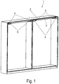
- a cupboard 1 comprises a furniture body 2, on which a rail 3 is fixed in order to store several run parts 4 of a fitting for a sliding door movable.
- the runners 4 can cooperate in an end position with a self-closing mechanism 5 to pull the sliding door into an end position.
- the self-closing 5 can also provide a corresponding damping in the opening or closing direction.
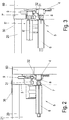
- FIG. 2 the fitting is shown in a side view.
- the rail 3 is fixed with an upper horizontal leg 30 to a top floor 20 of the furniture body 2.
- two U-shaped raceways 31 and 32 are formed for rollers 9.
- the rail 3 has only one track or more than two raceways for guiding rollers 9.
- the self-closing 5 comprises a housing 6 which is fixed to a rail 3 of the furniture body 2.
- a movable carrier 7 is provided, which is movable along a guideway and corresponding opening, closing and / or damping forces on an activator 8 transmits, which is fixed to a running part 4.
- the running part 4 is fixed to the back of a front panel 60 of a sliding door, wherein per 60 front plate two spaced running parts 4 are provided. The number and position of the runners 4 can be selected depending on the weight of the front panel 60.
- FIG. 3 a modified embodiment of a fitting is shown in which, in addition to the in FIG. 2 shown embodiment, a further self-closing 5 'is provided, which has a housing 6', on which a driver 7 'is movably mounted.
- the driver 7 'can in turn be moved along a guideway and biased by a spring into a starting position.
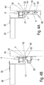
- FIG. 4A is the fitting of FIG. 2 shown in a mounting position.
- the activator 8 comprises a projection 80 which protrudes substantially perpendicularly from the plane of the front plate 60, the activator being oriented downwards in the mounting position.
- the activator 8 is rotatably mounted about an axis 83, wherein in a mounting position between an upper surface 84 and a lower side of the rail 3, a gap L is present, which allows lifting of the running part 4 with the front panel 60.
- the gap L is greater than a vertical portion of a side wall 33 which limits the track 32.
- FIG. 4B is the fitting of FIG. 4A shown in a functional position.
- the activator 8 has been pivoted by about 90 °, so that the projection 80 is no longer positioned below the axis 83, but substantially at the same level with this.
- the projection 80 of the activator 8 can engage a driver 7 of a self-closing mechanism, as shown in FIG FIG. 2 is shown.
- a stop 85 is further arranged below the rail 3, which is arranged closer to the rail 3 than the surface 84.
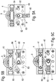
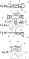
- FIGS. 5A to 5C is the running part 4 of the fitting of FIG. 2 shown in detail.
- the running part 4 comprises a plate-shaped support 40 on which a holder 41 is mounted. Between the holder 41 and the plate-shaped carrier 40, a roller 9 is rotatably mounted, wherein on the carrier 40, if necessary, a plurality of rollers 9 can be provided.
- Below the roller 9 is the rotatably mounted activator 8, the in FIG. 5A is shown in a mounting position. From this mounting position, the activator 8 can be selectively pivoted clockwise or counterclockwise to be brought into a functional position. In FIG. 5B the activator 8 has been pivoted to the right, so that the projection 80 can now engage with a driver on the right side of the carrier 40.
- the activator 8 is thereby up to a stop 86 on the carrier 40th pivoted, which is formed for example by an embossing. Alternatively, the activator 8 can also be pivoted clockwise by 90 °, as in FIG. 5C is shown. The activator is now directed to the left, and the protrusion 80 is disposed on a left side of the carrier 40. The activator 8 can be in the functional positions in the Figures 5B and 5C be locked so that a stable arrangement is ensured. By pivoting the activator 8 is determined whether the running part 4 is a right or left running part, so that identical parts running 4 can be delivered and is decided only during assembly, whether it is a right or a left-hand component.
- the activator 8 comprises an undercut receptacle into which a mushroom-shaped bolt 82 or a rivet can be inserted.
- the bolt 82 comprises a widened head portion, so that a withdrawal of the activator 8 from the plate-shaped support 40 can be prevented. This increases the stability of the activator 8 and reduces the load on the central axis 83.
- the axis 83 may also be formed as a mushroom-shaped bolt or rivet to rotatably support the activator 8 on the carrier 40.
- a mushroom-shaped bolt 82 is fixed to the support 40 on opposite sides, which may pass depending on the rotational movement of the activator 80 into engagement with the corresponding receptacle or not.
- the stop 86 is shown in detail on the plate-shaped carrier 40, which is designed as a stamping and forms a stop for the activator 8. Further, it can be seen that the activator 8 has a channel to receive the mushroom-headed bolt 82. On the channel, a latching spring bar 87 may be provided to lock the activator 8 in a functional position and to avoid accidental release.
- FIGS. 7A and 7B a modified embodiment of a fitting is shown, which is essentially the in FIG. 5 and 6 corresponds to fitting shown.
- a flared tab 92 is provided on the plate-shaped support 40, on which an opening 94 is formed.
- the activator 8 can be latched on the tab 92 instead of on the mushroom-shaped bolt 82, for which purpose a latching nub 93 engages in the opening 94.
- the fitting corresponds to the previous embodiment.
- FIGS. 8A to 8C a further embodiment of a fitting is shown, in which in the plate-shaped support 40, a stop 86 is provided, on which the activator 8 can be applied.
- the activator 8 is also in a functional position beyond the plate-shaped support 40, so that an edge 103 rests against an end edge of the plate-shaped support 40.
- the stability of the activator 8 can be additionally increased.
- the running part 4 corresponds to the previous embodiments.
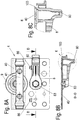
- FIGS. 9A to 9C a further embodiment of a running part of a fitting according to the invention.
- the running part comprises a plate-shaped support 40 on which a roller 9 is rotatably mounted.
- a displaceable activator 10 is provided, which is movable along a curve guide.
- two mushroom-shaped bolts 13 are fixed to the plate-shaped support 40, each engaging in a guide track 11.
- two guide tracks 11 are formed on the activator 10, which have an angled portion 12.
- On the activator 10 a protruding perpendicularly from the plane of the front plate 60 projection 14 is formed, which can get into engagement with a receptacle on a driver 7.
- FIG. 9D the activator 10 is shown in a mounting position. In this position, the roller 9 can be hung on a rail 3 on a top floor 20. Once the assembly is done, the activator 10 can be moved along the mushroom-shaped bolt 13 until the in Figure 9A shown position is reached. The activator 10 has been shifted so that below the roller 9 now a stop 15 of the activator 10 is provided, which prevents lifting of the running part. In this case, a spring 16 presses the activator 10 down to avoid accidental release of the activator 10 from the functional position. By the spring 16, the mushroom-shaped bolts 13 are held locked at an angled end portion 17. The locked end portion 17 is formed only on the left guideway 11, but it would also be possible to provide such a lock on the right guideway 11. If the running part is to be lifted off the rail 3, the activator 10 must first be moved along the guide track 11 again, in order then to raise the roller 9 accordingly and to be able to lift it out of the rail 3.
- the plate-shaped carrier 40 of the running part 4 can be made in the embodiments of a stamped and bent metal sheet.
- the activators 8 are mounted pivotably or displaceably. Of course, it is also possible to prefer other mechanisms for moving the activator in order to bring it from a mounting position into a functional position.
- the application of the fitting is not limited to furniture, sliding doors or sliding elements can also be used in household appliances or other areas.
Landscapes
- Engineering & Computer Science (AREA)
- Mechanical Engineering (AREA)
- Support Devices For Sliding Doors (AREA)
- Power-Operated Mechanisms For Wings (AREA)
- Hinge Accessories (AREA)
- Civil Engineering (AREA)
- Structural Engineering (AREA)
- Closing And Opening Devices For Wings, And Checks For Wings (AREA)
Priority Applications (2)
| Application Number | Priority Date | Filing Date | Title |
|---|---|---|---|
| PL14755847T PL3042016T3 (pl) | 2013-09-05 | 2014-08-28 | Okucie dla drzwi przesuwnych |
| SI201430555T SI3042016T1 (en) | 2013-09-05 | 2014-08-28 | Sliding door fittings |
Applications Claiming Priority (2)
| Application Number | Priority Date | Filing Date | Title |
|---|---|---|---|
| DE102013109710.3A DE102013109710A1 (de) | 2013-09-05 | 2013-09-05 | Beschlag für eine Schiebetür |
| PCT/EP2014/068276 WO2015032684A1 (de) | 2013-09-05 | 2014-08-28 | Beschlag für eine schiebetür |
Publications (2)
| Publication Number | Publication Date |
|---|---|
| EP3042016A1 EP3042016A1 (de) | 2016-07-13 |
| EP3042016B1 true EP3042016B1 (de) | 2017-10-18 |
Family
ID=51417286
Family Applications (1)
| Application Number | Title | Priority Date | Filing Date |
|---|---|---|---|
| EP14755847.2A Active EP3042016B1 (de) | 2013-09-05 | 2014-08-28 | Beschlag für eine schiebetür |
Country Status (11)
| Country | Link |
|---|---|
| EP (1) | EP3042016B1 (pl) |
| JP (1) | JP6586421B2 (pl) |
| KR (1) | KR102339313B1 (pl) |
| CN (1) | CN105518238B (pl) |
| DE (1) | DE102013109710A1 (pl) |
| ES (1) | ES2655859T3 (pl) |
| PL (1) | PL3042016T3 (pl) |
| RU (1) | RU2654392C2 (pl) |
| SI (1) | SI3042016T1 (pl) |
| TW (1) | TWI638085B (pl) |
| WO (1) | WO2015032684A1 (pl) |
Cited By (1)
| Publication number | Priority date | Publication date | Assignee | Title |
|---|---|---|---|---|
| WO2021221579A1 (en) | 2020-04-29 | 2021-11-04 | Çemobsan Metal Ve Plasti̇k Sanayi̇ Ti̇caret Li̇mi̇ted Şi̇rketi̇ | A sliding system |
Families Citing this family (5)
| Publication number | Priority date | Publication date | Assignee | Title |
|---|---|---|---|---|
| DE102012103629A1 (de) * | 2012-04-25 | 2013-10-31 | Hettich-Oni Gmbh & Co. Kg | Schlepptürbeschlag |
| ES2593107B1 (es) * | 2015-06-04 | 2017-10-03 | Industrias Auxiliares, S.A. (Indaux) | Seguro anti-descarrilamiento en escuadra de carro superior de puerta corredera interna |
| DE202016000481U1 (de) * | 2016-01-27 | 2016-02-11 | Erhardt Markisenbau Gmbh | Vorrichtung zum Verschließen von Gebäudeöffnungen |
| JP6391748B1 (ja) * | 2017-03-31 | 2018-09-19 | アクシス株式会社 | 引き戸支持装置 |
| US11781361B2 (en) | 2019-06-11 | 2023-10-10 | Terno Scorrevoli S.P.A. Unipersonale | Apparatus for moving sliding doors and wardrobe doors |
Family Cites Families (11)
| Publication number | Priority date | Publication date | Assignee | Title |
|---|---|---|---|---|
| US4987638A (en) * | 1988-05-05 | 1991-01-29 | Nickolas Ribaudo | Sliding door assembly |
| ITBL20070017A1 (it) * | 2007-06-29 | 2008-12-30 | Bortoluzzi Mobili Srl | Dispositivo perfezionato per la chiusura complanare di porte scorrevoli, in particolare per mobili a due o piu ante. |
| DE202007009341U1 (de) * | 2007-07-03 | 2008-11-13 | Hettich-Heinze Gmbh & Co. Kg | Schiebetürbeschlag |
| DE202009005269U1 (de) * | 2009-09-10 | 2011-01-20 | Hettich-Heinze Gmbh & Co. Kg | Laufteil für einen Schiebetürflügel |
| DE202009014882U1 (de) * | 2009-12-18 | 2011-05-05 | Hettich-Heinze Gmbh & Co. Kg | Beschlaggarnitur für zwei Schiebetürflügel |
| KR101077227B1 (ko) * | 2010-03-10 | 2011-10-27 | (주)삼우 | 자동개폐 기능이 구비된 호차 |
| DE102010037826A1 (de) * | 2010-09-24 | 2012-03-29 | Paul Hettich Gmbh & Co. Kg | Selbsteinzugsvorrichtung für ein verschiebbares Möbelteil |
| DE102010037773A1 (de) * | 2010-09-24 | 2012-03-29 | Hettich-Heinze Gmbh & Co. Kg | Führungsbeschlag |
| DE102010038141A1 (de) * | 2010-10-13 | 2012-04-19 | Hettich-Heinze Gmbh & Co. Kg | Beschlag für eine Schiebetür |
| DE102011050394A1 (de) * | 2011-05-17 | 2012-11-22 | Hettich-Heinze Gmbh & Co. Kg | Beschlag für eine Schiebetür |
| KR101068926B1 (ko) * | 2011-06-17 | 2011-10-04 | (주)메탈프린스 | 붙박이장의 내측도어용 롤러 이탈 방지장치 |
-
2013
- 2013-09-05 DE DE102013109710.3A patent/DE102013109710A1/de not_active Withdrawn
-
2014
- 2014-08-06 TW TW103126837A patent/TWI638085B/zh not_active IP Right Cessation
- 2014-08-28 JP JP2016539480A patent/JP6586421B2/ja not_active Expired - Fee Related
- 2014-08-28 RU RU2016109547A patent/RU2654392C2/ru active
- 2014-08-28 SI SI201430555T patent/SI3042016T1/en unknown
- 2014-08-28 WO PCT/EP2014/068276 patent/WO2015032684A1/de not_active Ceased
- 2014-08-28 KR KR1020167006831A patent/KR102339313B1/ko active Active
- 2014-08-28 PL PL14755847T patent/PL3042016T3/pl unknown
- 2014-08-28 EP EP14755847.2A patent/EP3042016B1/de active Active
- 2014-08-28 ES ES14755847.2T patent/ES2655859T3/es active Active
- 2014-08-28 CN CN201480048389.5A patent/CN105518238B/zh active Active
Non-Patent Citations (1)
| Title |
|---|
| None * |
Cited By (2)
| Publication number | Priority date | Publication date | Assignee | Title |
|---|---|---|---|---|
| WO2021221579A1 (en) | 2020-04-29 | 2021-11-04 | Çemobsan Metal Ve Plasti̇k Sanayi̇ Ti̇caret Li̇mi̇ted Şi̇rketi̇ | A sliding system |
| EP3997296A4 (en) * | 2020-04-29 | 2022-09-14 | Cemobsan Metal Ve Plastik Sanayi Ticaret Limited Sirketi | SLIDING SYSTEM |
Also Published As
| Publication number | Publication date |
|---|---|
| TW201520413A (zh) | 2015-06-01 |
| TWI638085B (zh) | 2018-10-11 |
| RU2016109547A (ru) | 2017-10-09 |
| JP6586421B2 (ja) | 2019-10-02 |
| WO2015032684A1 (de) | 2015-03-12 |
| SI3042016T1 (en) | 2018-02-28 |
| JP2016534259A (ja) | 2016-11-04 |
| EP3042016A1 (de) | 2016-07-13 |
| CN105518238A (zh) | 2016-04-20 |
| DE102013109710A1 (de) | 2015-03-05 |
| ES2655859T3 (es) | 2018-02-21 |
| RU2016109547A3 (pl) | 2018-03-26 |
| KR20160051786A (ko) | 2016-05-11 |
| RU2654392C2 (ru) | 2018-05-17 |
| CN105518238B (zh) | 2017-05-31 |
| KR102339313B1 (ko) | 2021-12-13 |
| PL3042016T3 (pl) | 2018-03-30 |
Similar Documents
| Publication | Publication Date | Title |
|---|---|---|
| EP3042016B1 (de) | Beschlag für eine schiebetür | |
| EP1550385A2 (de) | Vorrichtung zur Höhenverstellung einer Schublade | |
| AT521105B1 (de) | Ladenschiene für eine Schubladenausziehführung | |
| EP3713448B1 (de) | Vorrichtung zum festlegen eines schubelementes und möbel | |
| EP3684223B1 (de) | Kupplungsvorrichtung für schubkasten mit nachverrastung | |
| WO2016005259A1 (de) | Beschlag für eine schiebetür | |
| WO2012110373A1 (de) | Vorrichtung zur verriegelung relativ zueinander beweglicher teile | |
| EP2336468B1 (de) | Beschlaggarnitur für zwei Schiebetürflügel | |
| DE202017007566U1 (de) | Möbel mit einem an einem Laufprofil verfahrbaren Schiebeelement und einer Führungseinrichtung | |
| EP2951374B1 (de) | Laufteil zum führen eines möbelteils in einer führungsrichtung über eine führungsschiene und möbelbeschlag | |
| EP3189749B1 (de) | Ausziehführung für ein bewegbares möbelteil | |
| EP4240932B1 (de) | Möbel und verfahren zur montage einer schiebetür an einem möbelkorpus | |
| EP3167134B1 (de) | Beschlag für eine schiebetür | |
| EP3851621B1 (de) | Schiebetürsystem | |
| EP3511504B1 (de) | Teleskopschiebetürsystem | |
| EP3256677B1 (de) | Beschlag für mindestens einen linear verfahrbaren flügel und möbel | |
| WO2018162320A1 (de) | Montageeinheit und verfahren zur montage einer führungsschiene an einem oberboden oder boden eines möbels | |
| EP3757325A1 (de) | Schiebetürsystem | |
| DE202014103099U1 (de) | Beschlag für eine Schiebetür |
Legal Events
| Date | Code | Title | Description |
|---|---|---|---|
| PUAI | Public reference made under article 153(3) epc to a published international application that has entered the european phase |
Free format text: ORIGINAL CODE: 0009012 |
|
| 17P | Request for examination filed |
Effective date: 20160329 |
|
| AK | Designated contracting states |
Kind code of ref document: A1 Designated state(s): AL AT BE BG CH CY CZ DE DK EE ES FI FR GB GR HR HU IE IS IT LI LT LU LV MC MK MT NL NO PL PT RO RS SE SI SK SM TR |
|
| AX | Request for extension of the european patent |
Extension state: BA ME |
|
| DAX | Request for extension of the european patent (deleted) | ||
| GRAP | Despatch of communication of intention to grant a patent |
Free format text: ORIGINAL CODE: EPIDOSNIGR1 |
|
| INTG | Intention to grant announced |
Effective date: 20170524 |
|
| GRAS | Grant fee paid |
Free format text: ORIGINAL CODE: EPIDOSNIGR3 |
|
| GRAA | (expected) grant |
Free format text: ORIGINAL CODE: 0009210 |
|
| AK | Designated contracting states |
Kind code of ref document: B1 Designated state(s): AL AT BE BG CH CY CZ DE DK EE ES FI FR GB GR HR HU IE IS IT LI LT LU LV MC MK MT NL NO PL PT RO RS SE SI SK SM TR |
|
| REG | Reference to a national code |
Ref country code: GB Ref legal event code: FG4D Free format text: NOT ENGLISH |
|
| REG | Reference to a national code |
Ref country code: CH Ref legal event code: EP |
|
| REG | Reference to a national code |
Ref country code: AT Ref legal event code: REF Ref document number: 938107 Country of ref document: AT Kind code of ref document: T Effective date: 20171115 Ref country code: IE Ref legal event code: FG4D Free format text: LANGUAGE OF EP DOCUMENT: GERMAN |
|
| REG | Reference to a national code |
Ref country code: DE Ref legal event code: R096 Ref document number: 502014005882 Country of ref document: DE Ref country code: CH Ref legal event code: NV Representative=s name: ISLER AND PEDRAZZINI AG, CH |
|
| REG | Reference to a national code |
Ref country code: ES Ref legal event code: FG2A Ref document number: 2655859 Country of ref document: ES Kind code of ref document: T3 Effective date: 20180221 Ref country code: NL Ref legal event code: MP Effective date: 20171018 |
|
| REG | Reference to a national code |
Ref country code: LT Ref legal event code: MG4D |
|
| PG25 | Lapsed in a contracting state [announced via postgrant information from national office to epo] |
Ref country code: NL Free format text: LAPSE BECAUSE OF FAILURE TO SUBMIT A TRANSLATION OF THE DESCRIPTION OR TO PAY THE FEE WITHIN THE PRESCRIBED TIME-LIMIT Effective date: 20171018 |
|
| PG25 | Lapsed in a contracting state [announced via postgrant information from national office to epo] |
Ref country code: FI Free format text: LAPSE BECAUSE OF FAILURE TO SUBMIT A TRANSLATION OF THE DESCRIPTION OR TO PAY THE FEE WITHIN THE PRESCRIBED TIME-LIMIT Effective date: 20171018 Ref country code: SE Free format text: LAPSE BECAUSE OF FAILURE TO SUBMIT A TRANSLATION OF THE DESCRIPTION OR TO PAY THE FEE WITHIN THE PRESCRIBED TIME-LIMIT Effective date: 20171018 Ref country code: NO Free format text: LAPSE BECAUSE OF FAILURE TO SUBMIT A TRANSLATION OF THE DESCRIPTION OR TO PAY THE FEE WITHIN THE PRESCRIBED TIME-LIMIT Effective date: 20180118 Ref country code: LT Free format text: LAPSE BECAUSE OF FAILURE TO SUBMIT A TRANSLATION OF THE DESCRIPTION OR TO PAY THE FEE WITHIN THE PRESCRIBED TIME-LIMIT Effective date: 20171018 |
|
| PG25 | Lapsed in a contracting state [announced via postgrant information from national office to epo] |
Ref country code: GR Free format text: LAPSE BECAUSE OF FAILURE TO SUBMIT A TRANSLATION OF THE DESCRIPTION OR TO PAY THE FEE WITHIN THE PRESCRIBED TIME-LIMIT Effective date: 20180119 Ref country code: HR Free format text: LAPSE BECAUSE OF FAILURE TO SUBMIT A TRANSLATION OF THE DESCRIPTION OR TO PAY THE FEE WITHIN THE PRESCRIBED TIME-LIMIT Effective date: 20171018 Ref country code: RS Free format text: LAPSE BECAUSE OF FAILURE TO SUBMIT A TRANSLATION OF THE DESCRIPTION OR TO PAY THE FEE WITHIN THE PRESCRIBED TIME-LIMIT Effective date: 20171018 Ref country code: BG Free format text: LAPSE BECAUSE OF FAILURE TO SUBMIT A TRANSLATION OF THE DESCRIPTION OR TO PAY THE FEE WITHIN THE PRESCRIBED TIME-LIMIT Effective date: 20180118 Ref country code: IS Free format text: LAPSE BECAUSE OF FAILURE TO SUBMIT A TRANSLATION OF THE DESCRIPTION OR TO PAY THE FEE WITHIN THE PRESCRIBED TIME-LIMIT Effective date: 20180218 Ref country code: LV Free format text: LAPSE BECAUSE OF FAILURE TO SUBMIT A TRANSLATION OF THE DESCRIPTION OR TO PAY THE FEE WITHIN THE PRESCRIBED TIME-LIMIT Effective date: 20171018 |
|
| REG | Reference to a national code |
Ref country code: DE Ref legal event code: R097 Ref document number: 502014005882 Country of ref document: DE |
|
| PG25 | Lapsed in a contracting state [announced via postgrant information from national office to epo] |
Ref country code: SK Free format text: LAPSE BECAUSE OF FAILURE TO SUBMIT A TRANSLATION OF THE DESCRIPTION OR TO PAY THE FEE WITHIN THE PRESCRIBED TIME-LIMIT Effective date: 20171018 Ref country code: DK Free format text: LAPSE BECAUSE OF FAILURE TO SUBMIT A TRANSLATION OF THE DESCRIPTION OR TO PAY THE FEE WITHIN THE PRESCRIBED TIME-LIMIT Effective date: 20171018 Ref country code: EE Free format text: LAPSE BECAUSE OF FAILURE TO SUBMIT A TRANSLATION OF THE DESCRIPTION OR TO PAY THE FEE WITHIN THE PRESCRIBED TIME-LIMIT Effective date: 20171018 Ref country code: CZ Free format text: LAPSE BECAUSE OF FAILURE TO SUBMIT A TRANSLATION OF THE DESCRIPTION OR TO PAY THE FEE WITHIN THE PRESCRIBED TIME-LIMIT Effective date: 20171018 |
|
| PLBE | No opposition filed within time limit |
Free format text: ORIGINAL CODE: 0009261 |
|
| REG | Reference to a national code |
Ref country code: FR Ref legal event code: PLFP Year of fee payment: 5 |
|
| STAA | Information on the status of an ep patent application or granted ep patent |
Free format text: STATUS: NO OPPOSITION FILED WITHIN TIME LIMIT |
|
| REG | Reference to a national code |
Ref country code: DE Ref legal event code: R084 Ref document number: 502014005882 Country of ref document: DE |
|
| PG25 | Lapsed in a contracting state [announced via postgrant information from national office to epo] |
Ref country code: SM Free format text: LAPSE BECAUSE OF FAILURE TO SUBMIT A TRANSLATION OF THE DESCRIPTION OR TO PAY THE FEE WITHIN THE PRESCRIBED TIME-LIMIT Effective date: 20171018 Ref country code: RO Free format text: LAPSE BECAUSE OF FAILURE TO SUBMIT A TRANSLATION OF THE DESCRIPTION OR TO PAY THE FEE WITHIN THE PRESCRIBED TIME-LIMIT Effective date: 20171018 |
|
| 26N | No opposition filed |
Effective date: 20180719 |
|
| PG25 | Lapsed in a contracting state [announced via postgrant information from national office to epo] |
Ref country code: MT Free format text: LAPSE BECAUSE OF FAILURE TO SUBMIT A TRANSLATION OF THE DESCRIPTION OR TO PAY THE FEE WITHIN THE PRESCRIBED TIME-LIMIT Effective date: 20171018 |
|
| PG25 | Lapsed in a contracting state [announced via postgrant information from national office to epo] |
Ref country code: MC Free format text: LAPSE BECAUSE OF FAILURE TO SUBMIT A TRANSLATION OF THE DESCRIPTION OR TO PAY THE FEE WITHIN THE PRESCRIBED TIME-LIMIT Effective date: 20171018 |
|
| PG25 | Lapsed in a contracting state [announced via postgrant information from national office to epo] |
Ref country code: LU Free format text: LAPSE BECAUSE OF NON-PAYMENT OF DUE FEES Effective date: 20180828 |
|
| REG | Reference to a national code |
Ref country code: BE Ref legal event code: MM Effective date: 20180831 |
|
| PG25 | Lapsed in a contracting state [announced via postgrant information from national office to epo] |
Ref country code: BE Free format text: LAPSE BECAUSE OF NON-PAYMENT OF DUE FEES Effective date: 20180831 |
|
| PG25 | Lapsed in a contracting state [announced via postgrant information from national office to epo] |
Ref country code: PT Free format text: LAPSE BECAUSE OF FAILURE TO SUBMIT A TRANSLATION OF THE DESCRIPTION OR TO PAY THE FEE WITHIN THE PRESCRIBED TIME-LIMIT Effective date: 20171018 |
|
| PG25 | Lapsed in a contracting state [announced via postgrant information from national office to epo] |
Ref country code: IE Free format text: LAPSE BECAUSE OF NON-PAYMENT OF DUE FEES Effective date: 20180828 Ref country code: MK Free format text: LAPSE BECAUSE OF NON-PAYMENT OF DUE FEES Effective date: 20171018 Ref country code: HU Free format text: LAPSE BECAUSE OF FAILURE TO SUBMIT A TRANSLATION OF THE DESCRIPTION OR TO PAY THE FEE WITHIN THE PRESCRIBED TIME-LIMIT; INVALID AB INITIO Effective date: 20140828 Ref country code: CY Free format text: LAPSE BECAUSE OF FAILURE TO SUBMIT A TRANSLATION OF THE DESCRIPTION OR TO PAY THE FEE WITHIN THE PRESCRIBED TIME-LIMIT Effective date: 20171018 |
|
| PG25 | Lapsed in a contracting state [announced via postgrant information from national office to epo] |
Ref country code: AL Free format text: LAPSE BECAUSE OF FAILURE TO SUBMIT A TRANSLATION OF THE DESCRIPTION OR TO PAY THE FEE WITHIN THE PRESCRIBED TIME-LIMIT Effective date: 20171018 |
|
| REG | Reference to a national code |
Ref country code: AT Ref legal event code: MM01 Ref document number: 938107 Country of ref document: AT Kind code of ref document: T Effective date: 20190828 |
|
| PG25 | Lapsed in a contracting state [announced via postgrant information from national office to epo] |
Ref country code: AT Free format text: LAPSE BECAUSE OF NON-PAYMENT OF DUE FEES Effective date: 20190828 |
|
| PGFP | Annual fee paid to national office [announced via postgrant information from national office to epo] |
Ref country code: GB Payment date: 20220824 Year of fee payment: 9 |
|
| PGFP | Annual fee paid to national office [announced via postgrant information from national office to epo] |
Ref country code: SI Payment date: 20220819 Year of fee payment: 9 Ref country code: FR Payment date: 20220822 Year of fee payment: 9 |
|
| REG | Reference to a national code |
Ref country code: ES Ref legal event code: GC2A Effective date: 20230123 |
|
| P01 | Opt-out of the competence of the unified patent court (upc) registered |
Effective date: 20230407 |
|
| GBPC | Gb: european patent ceased through non-payment of renewal fee |
Effective date: 20230828 |
|
| PG25 | Lapsed in a contracting state [announced via postgrant information from national office to epo] |
Ref country code: SI Free format text: LAPSE BECAUSE OF NON-PAYMENT OF DUE FEES Effective date: 20230829 |
|
| PG25 | Lapsed in a contracting state [announced via postgrant information from national office to epo] |
Ref country code: SI Free format text: LAPSE BECAUSE OF NON-PAYMENT OF DUE FEES Effective date: 20230829 |
|
| REG | Reference to a national code |
Ref country code: SI Ref legal event code: KO00 Effective date: 20240429 |
|
| PG25 | Lapsed in a contracting state [announced via postgrant information from national office to epo] |
Ref country code: GB Free format text: LAPSE BECAUSE OF NON-PAYMENT OF DUE FEES Effective date: 20230828 |
|
| PG25 | Lapsed in a contracting state [announced via postgrant information from national office to epo] |
Ref country code: GB Free format text: LAPSE BECAUSE OF NON-PAYMENT OF DUE FEES Effective date: 20230828 Ref country code: FR Free format text: LAPSE BECAUSE OF NON-PAYMENT OF DUE FEES Effective date: 20230831 |
|
| PGFP | Annual fee paid to national office [announced via postgrant information from national office to epo] |
Ref country code: ES Payment date: 20250917 Year of fee payment: 12 |
|
| PGFP | Annual fee paid to national office [announced via postgrant information from national office to epo] |
Ref country code: DE Payment date: 20250819 Year of fee payment: 12 |
|
| PGFP | Annual fee paid to national office [announced via postgrant information from national office to epo] |
Ref country code: TR Payment date: 20250820 Year of fee payment: 12 Ref country code: PL Payment date: 20250819 Year of fee payment: 12 Ref country code: IT Payment date: 20250829 Year of fee payment: 12 |
|
| PGFP | Annual fee paid to national office [announced via postgrant information from national office to epo] |
Ref country code: CH Payment date: 20250901 Year of fee payment: 12 |