EP3037641B1 - Control device for turbocharger - Google Patents
Control device for turbocharger Download PDFInfo
- Publication number
- EP3037641B1 EP3037641B1 EP14868701.5A EP14868701A EP3037641B1 EP 3037641 B1 EP3037641 B1 EP 3037641B1 EP 14868701 A EP14868701 A EP 14868701A EP 3037641 B1 EP3037641 B1 EP 3037641B1
- Authority
- EP
- European Patent Office
- Prior art keywords
- turbocharger
- efficiency
- deterioration
- characteristic parameter
- map
- Prior art date
- Legal status (The legal status is an assumption and is not a legal conclusion. Google has not performed a legal analysis and makes no representation as to the accuracy of the status listed.)
- Not-in-force
Links
- 230000006866 deterioration Effects 0.000 claims description 73
- 238000001514 detection method Methods 0.000 claims description 31
- 238000004364 calculation method Methods 0.000 claims description 22
- 238000005259 measurement Methods 0.000 claims description 14
- 238000002485 combustion reaction Methods 0.000 claims description 12
- 238000012423 maintenance Methods 0.000 claims description 11
- 238000000034 method Methods 0.000 description 14
- 230000007257 malfunction Effects 0.000 description 12
- 238000010586 diagram Methods 0.000 description 8
- 230000007423 decrease Effects 0.000 description 5
- 239000000446 fuel Substances 0.000 description 4
- 238000004140 cleaning Methods 0.000 description 3
- 238000002347 injection Methods 0.000 description 3
- 239000007924 injection Substances 0.000 description 3
- 238000004939 coking Methods 0.000 description 2
- 238000013461 design Methods 0.000 description 2
- 238000011161 development Methods 0.000 description 2
- 230000018109 developmental process Effects 0.000 description 2
- 238000003745 diagnosis Methods 0.000 description 2
- 238000006073 displacement reaction Methods 0.000 description 2
- 239000000314 lubricant Substances 0.000 description 2
- 238000012544 monitoring process Methods 0.000 description 2
- 239000000126 substance Substances 0.000 description 2
- 230000005856 abnormality Effects 0.000 description 1
- 230000032683 aging Effects 0.000 description 1
- 230000003247 decreasing effect Effects 0.000 description 1
- 230000000694 effects Effects 0.000 description 1
- 239000000463 material Substances 0.000 description 1
- 238000011160 research Methods 0.000 description 1
- 238000004088 simulation Methods 0.000 description 1
- 239000000243 solution Substances 0.000 description 1
- 230000007704 transition Effects 0.000 description 1
- 238000011144 upstream manufacturing Methods 0.000 description 1
Images
Classifications
-
- F—MECHANICAL ENGINEERING; LIGHTING; HEATING; WEAPONS; BLASTING
- F02—COMBUSTION ENGINES; HOT-GAS OR COMBUSTION-PRODUCT ENGINE PLANTS
- F02D—CONTROLLING COMBUSTION ENGINES
- F02D41/00—Electrical control of supply of combustible mixture or its constituents
- F02D41/22—Safety or indicating devices for abnormal conditions
-
- F—MECHANICAL ENGINEERING; LIGHTING; HEATING; WEAPONS; BLASTING
- F02—COMBUSTION ENGINES; HOT-GAS OR COMBUSTION-PRODUCT ENGINE PLANTS
- F02B—INTERNAL-COMBUSTION PISTON ENGINES; COMBUSTION ENGINES IN GENERAL
- F02B39/00—Component parts, details, or accessories relating to, driven charging or scavenging pumps, not provided for in groups F02B33/00 - F02B37/00
- F02B39/16—Other safety measures for, or other control of, pumps
-
- F—MECHANICAL ENGINEERING; LIGHTING; HEATING; WEAPONS; BLASTING
- F02—COMBUSTION ENGINES; HOT-GAS OR COMBUSTION-PRODUCT ENGINE PLANTS
- F02B—INTERNAL-COMBUSTION PISTON ENGINES; COMBUSTION ENGINES IN GENERAL
- F02B37/00—Engines characterised by provision of pumps driven at least for part of the time by exhaust
- F02B37/12—Control of the pumps
-
- F—MECHANICAL ENGINEERING; LIGHTING; HEATING; WEAPONS; BLASTING
- F02—COMBUSTION ENGINES; HOT-GAS OR COMBUSTION-PRODUCT ENGINE PLANTS
- F02D—CONTROLLING COMBUSTION ENGINES
- F02D21/00—Controlling engines characterised by their being supplied with non-airborne oxygen or other non-fuel gas
- F02D21/06—Controlling engines characterised by their being supplied with non-airborne oxygen or other non-fuel gas peculiar to engines having other non-fuel gas added to combustion air
- F02D21/08—Controlling engines characterised by their being supplied with non-airborne oxygen or other non-fuel gas peculiar to engines having other non-fuel gas added to combustion air the other gas being the exhaust gas of engine
-
- F—MECHANICAL ENGINEERING; LIGHTING; HEATING; WEAPONS; BLASTING
- F02—COMBUSTION ENGINES; HOT-GAS OR COMBUSTION-PRODUCT ENGINE PLANTS
- F02D—CONTROLLING COMBUSTION ENGINES
- F02D41/00—Electrical control of supply of combustible mixture or its constituents
- F02D41/0002—Controlling intake air
- F02D41/0007—Controlling intake air for control of turbo-charged or super-charged engines
-
- F—MECHANICAL ENGINEERING; LIGHTING; HEATING; WEAPONS; BLASTING
- F02—COMBUSTION ENGINES; HOT-GAS OR COMBUSTION-PRODUCT ENGINE PLANTS
- F02D—CONTROLLING COMBUSTION ENGINES
- F02D41/00—Electrical control of supply of combustible mixture or its constituents
- F02D41/22—Safety or indicating devices for abnormal conditions
- F02D41/221—Safety or indicating devices for abnormal conditions relating to the failure of actuators or electrically driven elements
-
- F—MECHANICAL ENGINEERING; LIGHTING; HEATING; WEAPONS; BLASTING
- F02—COMBUSTION ENGINES; HOT-GAS OR COMBUSTION-PRODUCT ENGINE PLANTS
- F02B—INTERNAL-COMBUSTION PISTON ENGINES; COMBUSTION ENGINES IN GENERAL
- F02B39/00—Component parts, details, or accessories relating to, driven charging or scavenging pumps, not provided for in groups F02B33/00 - F02B37/00
- F02B39/16—Other safety measures for, or other control of, pumps
- F02B2039/162—Control of pump parameters to improve safety thereof
- F02B2039/166—Control of pump parameters to improve safety thereof the fluid pressure in the pump or exhaust drive being limited
-
- F—MECHANICAL ENGINEERING; LIGHTING; HEATING; WEAPONS; BLASTING
- F02—COMBUSTION ENGINES; HOT-GAS OR COMBUSTION-PRODUCT ENGINE PLANTS
- F02B—INTERNAL-COMBUSTION PISTON ENGINES; COMBUSTION ENGINES IN GENERAL
- F02B39/00—Component parts, details, or accessories relating to, driven charging or scavenging pumps, not provided for in groups F02B33/00 - F02B37/00
- F02B39/16—Other safety measures for, or other control of, pumps
- F02B2039/162—Control of pump parameters to improve safety thereof
- F02B2039/168—Control of pump parameters to improve safety thereof the rotational speed of pump or exhaust drive being limited
-
- F—MECHANICAL ENGINEERING; LIGHTING; HEATING; WEAPONS; BLASTING
- F02—COMBUSTION ENGINES; HOT-GAS OR COMBUSTION-PRODUCT ENGINE PLANTS
- F02D—CONTROLLING COMBUSTION ENGINES
- F02D41/00—Electrical control of supply of combustible mixture or its constituents
- F02D41/22—Safety or indicating devices for abnormal conditions
- F02D2041/228—Warning displays
-
- F—MECHANICAL ENGINEERING; LIGHTING; HEATING; WEAPONS; BLASTING
- F02—COMBUSTION ENGINES; HOT-GAS OR COMBUSTION-PRODUCT ENGINE PLANTS
- F02D—CONTROLLING COMBUSTION ENGINES
- F02D2200/00—Input parameters for engine control
- F02D2200/02—Input parameters for engine control the parameters being related to the engine
- F02D2200/04—Engine intake system parameters
- F02D2200/0406—Intake manifold pressure
-
- F—MECHANICAL ENGINEERING; LIGHTING; HEATING; WEAPONS; BLASTING
- F02—COMBUSTION ENGINES; HOT-GAS OR COMBUSTION-PRODUCT ENGINE PLANTS
- F02D—CONTROLLING COMBUSTION ENGINES
- F02D2200/00—Input parameters for engine control
- F02D2200/02—Input parameters for engine control the parameters being related to the engine
- F02D2200/04—Engine intake system parameters
- F02D2200/0414—Air temperature
-
- Y—GENERAL TAGGING OF NEW TECHNOLOGICAL DEVELOPMENTS; GENERAL TAGGING OF CROSS-SECTIONAL TECHNOLOGIES SPANNING OVER SEVERAL SECTIONS OF THE IPC; TECHNICAL SUBJECTS COVERED BY FORMER USPC CROSS-REFERENCE ART COLLECTIONS [XRACs] AND DIGESTS
- Y02—TECHNOLOGIES OR APPLICATIONS FOR MITIGATION OR ADAPTATION AGAINST CLIMATE CHANGE
- Y02T—CLIMATE CHANGE MITIGATION TECHNOLOGIES RELATED TO TRANSPORTATION
- Y02T10/00—Road transport of goods or passengers
- Y02T10/10—Internal combustion engine [ICE] based vehicles
- Y02T10/12—Improving ICE efficiencies
Definitions
- the present invention relates to a control device for a turbocharger for supplying compressed intake air to an engine used as a power source of a ship, a vehicle, or an industry machine, for instance.
- a typical turbocharger includes an exhaust turbine driven to rotate by exhaust gas flowing through an exhaust channel of an engine, and a compressor turbine for sending intake air in an intake channel into a combustion chamber, the exhaust turbine and the compressor turbine being coupled to each other.
- the exhaust turbine is driven to rotate by energy of exhaust gas, and the compressor turbine is driven to rotate in accordance with the exhaust turbine.
- the exhaust turbine and a turbo bearing are exposed to oil component contained in lubricant oil or exhaust gas under a high-temperature environment, and thus deterioration is likely to occur by sticking or coking of the oil component. Progress of such deterioration leads to wear of components of the turbocharger to decrease fuel-consumption performance of the engine, and even results in malfunction. Thus, early detection of deterioration is desirable.
- Document WO 03/071111 A1 discloses a method for monitoring the operation of a bypass element of the boost control of a turbo engine by detecting the boost pressure and comparing it with the ambient pressure.
- Document JP 2005 155384 relates to a method for performing failure diagnosis at a transition time when turbine rotation speed changes in relation to a failure diagnosis device for an internal combustion engine provided with a turbocharger.
- Patent Document 1 discloses a technique to detect deterioration of a turbocharger of such type.
- the technique to detect deterioration of a turbocharger disclosed in Patent Document 1 is for a turbocharger equipped with a waste-gate valve, and is to perform abnormality determination on the basis of whether a rotation-speed change that accompanies opening and closing of the waste-gate valve is in a predicted range.
- Patent Document 1 JP2013-19319A
- Patent Document 1 cannot be applied to a turbocharger not equipped with a waste-gate valve (for instance, to a turbocharger with a variable-vane control).
- the present invention was made in view of the above described problem, and an object of the present invention is to provide a control device for a turbocharger, whereby it is possible to detect deterioration of a turbocharger accurately.
- a control device for a turbocharger for supplying compressed intake air to an internal combustion engine comprises: a storage part configured to pre-store a map which defines a relationship between at least one characteristic parameter and an efficiency of the turbocharger; a detection part configured to detect the at least one characteristic parameter of the turbocharger; a calculation part configured to obtain the efficiency of the turbocharger on the basis of the detected at least one characteristic parameter; a determination part configured to determine presence of deterioration of the turbocharger by comparing the detected at least one characteristic parameter and the obtained efficiency with the map; and an informing part configured to inform a user of a maintenance request if the determination part determines that the deterioration is present.
- a relationship between the characteristic parameters of the turbocharger and the efficiency is defined in advance in form of a map, and the efficiency is compared with an efficiency obtained from the actual measurement of the characteristic parameters detected by the detection part, and thereby presence of deterioration of the turbocharger can be determined.
- the efficiency since the deterioration of the turbocharger is determined on the basis of the efficiency of the turbocharger, the efficiency directly reflecting an influence of the deterioration on fuel-consumption performance of the engine, it is possible to determine the deterioration state of the turbocharger accurately. If it is determined that there is deterioration, the informing part issues a maintenance request, which makes it possible for a user to recognize deterioration of the turbocharger in an early stage to take a suitable measure.
- the detection part is configured to detect the at least one characteristic parameter at a predetermined interval
- the calculation part is configured to calculate a mean value of the efficiency corresponding to the at least one characteristic parameter having a frequency greater than a predetermined value among the detected at least one characteristic parameter, and accumulate the mean value of the efficiency in the storage part as actual-measurement data associated with the corresponding at least one characteristic parameter
- the determination part is configured to determine presence of deterioration of the turbocharger by comparing an approximate curve obtained from the accumulated actual measurement data and a reference curve obtained from the map.
- deterioration is determined on the basis of a mean value of the efficiency obtained from characteristic parameters with a high frequency, which makes it possible to reduce an influence of errors and to improve reliability of deterioration determination effectively.
- the determination part may be configured to determine that the deterioration of the turbocharger is present, if a first zone in which the approximate curve is above the reference curve is smaller in area than a second zone in which the approximate curve is below the reference curve, in a space in which the characteristic parameter and the efficiency are variables.
- comparing statistically a relationship between the approximate curve obtained from the actual measurement data and the reference curve obtained from the map makes it possible to perform highly-reliable deterioration determination, as compared to a case in which deterioration determination is performed on the basis of whether a momentary detection result is greater than a reference value.
- the determination part is configured to determine that the turbocharger is malfunctioning if a change rate of the efficiency of the turbocharger is greater than a predetermined value on the basis of the accumulated actual-measurement data, and the informing part is configured to issue an alert if the determination part determines that the turbocharger is malfunctioning.
- a kind of malfunction of a turbocharger is accompanied by a rapid decrease in efficiency. According to the above aspect, if a change rate of efficiency of the turbocharger is so rapid that exceeds a threshold value, it is determined that the turbocharger is malfunctioning and the malfunctioning is notified distinctively from deterioration, which enables safe operation of the turbocharger.
- the at least one characteristic parameter comprises a speed ratio and a pressure ratio of the turbocharger
- the map is a three-dimensional map defining the efficiency corresponding to the speed ratio and the pressure ratio.
- an output interface capable of outputting the accumulated actual-measurement data to outside may be provided.
- actual measurement data used in the deterioration determination can be outputted via an output interface, which makes it possible to specifically determine an actual operational state of a turbocharger being actually used by a user. Such information is extremely useful in design development, for instance.
- a relationship between the characteristic parameters of the turbocharger and the efficiency is determined in advance in form of a map, and the efficiency is compared with the efficiency obtained from the actual measurement of the characteristic parameters detected by the detection part, and thereby presence of deterioration of the turbocharger can be determined.
- the efficiency since deterioration of the turbocharger is determined on the basis of the efficiency of the turbocharger, the efficiency directly reflecting an influence of the deterioration on fuel-consumption performance of the engine, it is possible to determine the deterioration state of the turbocharger accurately. If it is determined that there is deterioration, the informing part issues a maintenance request, which makes it possible for a user to recognize deterioration of the turbocharger in an early stage to take a suitable measure.
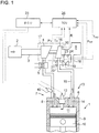
- FIG. 1 is a schematic diagram of an overall configuration of a turbo-charging system including a turbocharger according to the first embodiment.
- An engine 1 is a gasoline engine mounted to a vehicle, a ship, or an industrial machine, for instance, as a power source.
- Intake air introduced from an inlet 2 flows through an intake channel 3 to be compressed by a compressor 4.
- the intake air compressed by the compressor 4 is cooled by an inter cooler 5, and introduced into a combustion chamber 11 including a cylinder 9 and a piston 10 reciprocating in the cylinder 9 via an intake valve 8 from an intake port 7 disposed on a cylinder head 6.
- the intake air When being introduced into the combustion chamber 11, the intake air is mixed with fuel injected by a fuel injection device 40 disposed in the vicinity of an inlet of the intake port 7 to produce mixed gas, and the ignition device 12 combusts the mixed gas in the combustion chamber 11.
- Exhaust gas generated in the combustion chamber 11 is discharged to an exhaust channel 15 via an exhaust valve 14 from an exhaust port 13.
- the exhaust channel 15 includes an exhaust turbine 16 driven by exhaust gas of the engine 1.
- the exhaust turbine 16 is driven to rotate by exhaust gas, and thereby the compressor 4 coupled to the exhaust turbine 16 is driven to rotate. Accordingly, the exhaust turbine 16 and the compressor 4 constitute a turbocharger 17 which compresses intake air in the intake channel 3.
- a branch channel 18 is formed in the exhaust channel 15 so as to bypass the exhaust turbine 16.
- a waste-gate valve 19 is disposed in the branch channel 18.
- the exhaust turbine 16 is provided with a rotation speed sensor 20 for detecting a rotation speed of the exhaust turbine 16. Further, the exhaust turbine 16 is provided with an inlet temperature sensor 21 and an inlet pressure sensor 22 for detecting an inlet temperature T in and an inlet pressure P in of the exhaust turbine 16, respectively, and an outlet temperature sensor 23 and an outlet pressure sensor 24 for detecting an outlet temperature T out and an outlet pressure P out of the exhaust turbine 16, respectively.
- the operation state of the engine 1 is controlled by an engine control unit (ECU) 25.
- ECU engine control unit
- control signals to be sent to the fuel injection device 40 and the ignition device 12 are illustrated as representative control signals of the ECU 25, the control signals controlling fuel injection timing and amount, and an ignition timing of an injector, respectively.
- the operation state of the turbocharger 17 is controlled by a turbocharger control unit (TCU) 26.
- TCU turbocharger control unit
- FIG. 1 as representative control signals of the TCU 26, detection signals of the rotation speed sensor 20, the inlet temperature sensor 21, the inlet pressure sensor 22, the outlet temperature sensor 23, and the outlet pressure sensor 24 are obtained besides control signals for adjusting the opening degree of the waste-gate valve 19, and thereby performance deterioration of the exhaust turbocharger 17 can be determined on the basis of detection values of the detection signals, as described below.
- the ECU 25 and the TCU 26 may be formed integrally as a single unit.
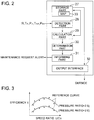
- FIG. 2 is a block functional diagram illustrating an interior configuration of the TCU 26.
- the TCU 26 includes a storage part 27, a detection part 28, a calculation part 29, a determination part 30, an informing part 31 and an output interface 32.
- the storage part 27 stores a map 33 which determines a relationship between a characteristic parameter and an efficiency of the turbocharger 17.
- the map 33 is stored in the storage part 27 prior to execution of a deterioration determination control, and is configured to be readable when appropriate in each step described below.
- the relationship between the characteristic parameter and the efficiency stored in the map 33 is determined for a sample (i.e., an ideal turbocharger 17) without deterioration, the sample serving as the basis of the deterioration determination, and the relationship may be defined in advance experimentally, theoretically, or on the basis of simulation.
- FIG. 3 is an example of the map 33 stored in the storage part 27, illustrating a relationship between a speed ratio and an efficiency at different pressure ratios.
- the efficiency of the turbocharger 17 stored in the map 33 can be approximated by a function including a pressure ratio and a speed ratio as variables.
- the approximate curves (hereinafter, referred to as "reference curves" where appropriate) are also shown in FIG. 3 .
- the detection part 28 obtains detection values from various sensors (the rotation speed sensor 20, the inlet temperature sensor 21, the inlet pressure sensor 22, the outlet temperature sensor 23, and the outlet pressure sensor 24) disposed on the turbocharger 17.
- the calculation part 29 receives detection values obtained by the detection part 28, and calculates a speed ratio, a pressure ratio, and an efficiency required for the deterioration determination, on the basis of the detection values.
- the determination part 30 obtains a calculation result of the calculation part 29 and compares the calculation result with the map 33 stored in the storage part 27, thereby determining presence of deterioration of the turbocharger 17.
- the informing part 31 informs a user of a maintenance request if the determination part 30 determines that there is deterioration.
- a maintenance request widely includes information for having a user recognize deterioration of the exhaust turbocharger 17, in a broad sense.
- a user having received a maintenance request can take a countermeasure in an early stage to avoid an influence of reduced performance which accompanies deterioration of the turbocharger 17.
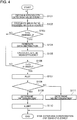
- FIG. 4 is a flowchart of a deterioration determination control executed by the TCU 26.
- the detection part 28 obtains detection values from various sensors at a regular interval of a predetermined period T1 (e.g. one second) (step S101).
- the detection values obtained by the detection part 28 may be accumulated in the storage part 27, and be readable by an external reader via the output interface 32 when appropriate.
- Such accumulated data is extremely advantageous in design development, for instance, because an actual operation state of the turbocharger 17 can be specifically determined from the accumulated data.
- the calculation part 29 receives detection values obtained by the detection part 28, and calculates a speed ratio, a pressure ratio, and an efficiency (step S102).
- the pressure ratio can be obtained by an expression of P out /P in , where P in is a detection pressure value of the inlet pressure sensor and P out is a detection pressure value of the outlet pressure sensor.
- calculation result obtained by the calculation part 29 also may be stored in the storage part 27 each time, and be readable by an external reader via the output interface 32 when appropriate.
- step S103 it is determined whether the time T is greater than a predetermined value T2 (>T1, e.g. 1800 seconds). If not greater than T2, the process returns to step S101, and the above process is repeated (step S103: NO). Specifically, steps S101 and S102 are repeated until the time T exceeds T2.
- T2 a predetermined value
- step S103 When the predetermined time T2 elapses, (step S103: YES), the calculation part 29 generates data distribution of data accumulated in the storage part 27 with respect to the speed ratio and the pressure ratio (step S104).
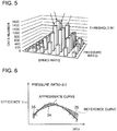
- FIG. 5 is an example of data distribution generated in step S104.
- y-axis represents the number of data with respect to combination of the speed ratio and the pressure ratio.
- the calculation part 29 obtains the mean value ⁇ ave of the efficiency for the characteristic parameters with a high repetition frequency as described above, and then resets the number of data only for the characteristic parameters used in the calculation (in other words, for the other characteristic parameters not having reached the reference value N1 in FIG. 5 , the number of data is maintained as it is, because the calculation of the efficiency is not performed by the calculation part 29).
- the calculation part 29 calculates a mean efficiency ⁇ ave with respect to a particular frequently-repeated combination of the speed ratio and the pressure ratio, for each time T2.
- step S106 it is determined whether the time T is greater than a predetermined value T3 (>T2, e.g. one week). If the time T is not greater than T3, the process returns to step S101, and the above process is repeated (step S106: NO). Specifically, the above calculation is repeated until the time T exceeds T3.
- step S106 When time T3 elapses (step S106: YES), the determination part 30 plots on a graph mean efficiencies ⁇ ave with respect to combinations of the speed ratio and the pressure ratio calculated so far (step S107), and compares the plotted graph with the reference curve obtained from the map 33, thereby determining presence of deterioration of the turbocharger 17 (step S108).
- FIG. 6 is an example of a plotted graph generated in step S107. While an example with a pressure ratio of 2.0 is illustrated in FIG. 6 , deterioration is also determined for other pressure ratios by plotting similar graphs.
- the determination part 30 obtains an approximate curve of the mean values ⁇ ave of the efficiency obtained in step S105, and compares the approximate curve with the reference curve obtained from the map 33, thereby determining presence of deterioration to the turbocharger 17.
- the approximate curve can be obtained by a known method, such as the mean-square method.
- zones surrounded by the approximate curve and the reference curve are shaded, and the first zone 34, where the approximate curve is greater than the reference curve, and the second zone 35, where the approximate curve is smaller than the reference curve, are discriminated.
- the determination part 30 adds up the area of the first zone 34 and the second zone 35, and if the total area is less than a criteria of a performance-decrease amount set in advance, determines that there is deterioration of the turbocharger 17 (step S109), the informing part 31 issues a maintenance request, and the process ends (step S110). Specifically, presence of deterioration of the exhaust turbocharger 17 is determined on the basis of whether the approximate curve is smaller than the reference curve statistically.
- the exhaust turbine and a turbo bearing are exposed to oil component contained in lubricant oil or exhaust gas under a high-temperature environment, and thus the exhaust turbine is likely to be deteriorated by sticking of or coking of the oil component. Such deterioration can be fixed by cleaning substances adhering to rotor blades of the exhaust turbine.
- a message or a sound may be outputted as a maintenance request to request cleaning of the substances adhering to the rotor blades of the exhaust turbine.
- a message or a sound may be outputted to request replacement of the deteriorated turbocharger 17.
- step S111 if the first zone 34 is larger in area than the second zone 35, it is determined that the exhaust turbocharger 17 is not deteriorated, and the process ends (steps S111).
- determining deterioration statistically on the basis of a relationship between the approximate curve obtained from the actual measurement data and the reference curve obtained from the map 33 makes it possible to perform highly-reliable deterioration determination, as compared to a case in which deterioration determination is performed merely on the basis of whether a momentary detection result is greater than a reference value for a moment.
- a relationship between the characteristic parameters and the efficiency of the turbocharger 17 is determined in advance in form of the map 33, and the efficiency is compared with an efficiency obtained from the actual measurement of the characteristic parameters detected by the detection part 28, and thereby presence of deterioration of the turbocharger 17 is determined.
- the efficiency since deterioration of the turbocharger 17 is determined on the basis of the efficiency of the turbocharger 17, the efficiency directly reflecting an influence of the deterioration on fuel-consumption performance of the engine 1, it is possible to determine the deterioration state of the turbocharger 17 accurately. If it is determined that there is deterioration, the informing part 31 issues a maintenance request, which makes it possible for a user to recognize deterioration of the turbocharger 17 in an early stage to take a suitable measure.
- the determination part 30 determines only the presence of deterioration of the turbocharger 17. Further to this, it is possible to determine not only deterioration but also malfunction of the turbocharger 17 distinctively by monitoring a time-series change of the efficiency obtained by the calculation part 29.
- the efficiency decreases gradually with time. In contrast, if a kind of malfunction is to occur in the turbocharger 17, the efficiency is predicted to change rapidly.
- a change rate of the mean value of the efficiency obtained in step S105 is obtained, and a time-series change of the change rate is monitored.
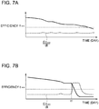
- FIGs. 7A and 7B are graphs showing a time-series change of a mean value ⁇ ave and its change rate d ⁇ ave /dt of efficiency in a normal state and a malfunction state.
- FIG. 7A shows a normal state, in which the efficiency ⁇ ave is gradually decreasing with time due to performance deterioration caused by aging, and the change rate d ⁇ ave /dt is substantially constant.
- FIG. 7B is showing a case in which malfunction is occurring at time t1, where the efficiency ⁇ ave decreases rapidly at time t1, when malfunction occurs, and the change rate d ⁇ ave /dt of the efficiency increases rapidly for a brief time.
- the determination part 30 has a threshold value d ⁇ ave /dt1 prepared in advance for the change rate d ⁇ ave /dt of the efficiency to detect malfunction, and determines that malfunction has occurred if the change rate d ⁇ ave /dt is greater than the threshold value d ⁇ ave /dt1.
- the informing part 31 issues an alert different from the maintenance request issued in case of deterioration, which makes it possible to have a user recognize occurrence of malfunction. Accordingly, informing a user of occurrence of malfunction distinctively from presence of deterioration enables highly-reliable operation of the turbocharger 17.
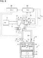
- FIG. 8 is a schematic diagram of an overall configuration of a turbo-charging system including a turbocharger according to the second embodiment.
- the present embodiment is basically similar to the embodiment illustrated in FIG. 1 in terms of configuration, except that the branch channel 18 and the waste-gate valve 19 are not provided. Thus, the same component is associated with the same reference numeral and not described in detail.
- the turbocharger 17 is a variable turbocharger including the exhaust turbine 16 driven to rotate by exhaust energy of exhaust gas discharged from the engine 1, the compressor 4 driven coaxially with the exhaust turbine 16, and a variable control mechanism 30 for controlling a flow of exhaust gas that flows into the exhaust turbine 16.
- the above described TCU 26 adjusts the variable control mechanism 30 to control a flow of exhaust gas flowing into the exhaust turbine 16, thereby controlling the boost pressure of the turbocharger 17.
- the TCU 26 obtains detection values from various sensors (the rotation speed sensor 20, the inlet temperature sensor 21, the inlet pressure sensor 22, the outlet temperature sensor 23, and the outlet pressure sensor 24) disposed on the turbocharger 17, and thereby performs the deterioration determination control on the turbocharger, similarly to the first embodiment.
- the deterioration determination control of the present invention can be similarly performed on a variable-displacement type turbocharger not including a waste-gate valve, because the control is based on the characteristic parameters and the efficiency ⁇ , which are basic characteristics independent from the configuration type of the turbocharger 17.
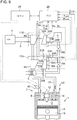
- FIG. 9 is a schematic diagram of an overall configuration of a turbo-charging system including a turbocharger according to the third embodiment.
- the present embodiment is basically similar to the embodiment illustrated in FIG. 1 in terms of configuration except that the present embodiment is a two-stage turbo-charging system includes two turbochargers, a high-pressure stage turbocharger 17A and a low-pressure stage turbocharger 17B.
- the same component is associated with the same reference numeral and not described in detail.
- the turbocharger for compressing intake air to be supplied to the engine 1 includes the high-pressure stage turbocharger 17A and the low-pressure stage turbocharger 17B.
- the high-pressure stage turbocharger 17A includes a high-pressure stage turbine 16A disposed in the exhaust channel 15 of the engine 1 and driven to rotate by exhaust energy from the engine 1 and a high-pressure stage compressor 4A disposed in the intake channel 3 of the engine 1 and driven coaxially with the high-pressure stage turbine 16A.
- the low-pressure stage turbocharger 17B includes a low-pressure stage turbine 16B disposed in the exhaust channel 15 and on the downstream side of the high-pressure stage turbine 16A and a low-pressure stage compressor 4B disposed in the intake channel 3 and on the upstream side of the high-pressure stage compressor 4A and driven coaxially with the low-pressure stage turbine 16B.
- a high-pressure stage branch channel 18A that bypasses the high-pressure stage turbine 16A and a low-pressure branch channel 18B that bypasses the low-pressure stage turbine 16B are connected to the exhaust channel 15 of the engine 1.
- a high-pressure stage waste-gate valve 19A is disposed in the high-pressure stage branch channel 18A, and a low-pressure stage waste-gate valve 18B is disposed in the low-pressure branch channel 18B.
- the above described TCU 26 adjusts the valve opening degree of the high-pressure stage waste-gate valve 19A and the low-pressure stage waste-gate valve 19B individually, thereby controlling the boost pressure of the high-pressure stage turbocharger 17A and the low-pressure stage turbocharger 17B individually.
- the high-pressure stage turbine 16A and the low-pressure stage turbine 16B include a rotation-speed sensor 20A and a rotation speed sensor 20B, respectively, for detecting the rotation speed of each turbine. Further, the high-pressure stage turbine 16A is provided with an inlet temperature sensor 21A and an inlet pressure sensor 22A for detecting an inlet temperature T in A and an inlet pressure P in A of the high-pressure stage turbine 16A, respectively, and an outlet temperature sensor 23A and an outlet pressure sensor 24A for detecting an outlet temperature T out A and an outlet pressure P out A of the high-pressure stage turbine 16A, respectively.
- the low-pressure stage turbine 16B is provided with an inlet temperature sensor 21B and an inlet pressure sensor 22B for detecting an inlet temperature T in B and an inlet pressure P in B of the low-pressure stage turbine 16B, respectively, and an outlet temperature sensor 23B and an outlet pressure sensor 24B for detecting an outlet temperature T out B and an outlet pressure P out B of the low-pressure stage turbine 16B, respectively.
- the TCU 26 obtains detection values from the above sensors, and thereby performs the deterioration determination control described specifically with reference to the first embodiment on the high-pressure stage turbocharger 17A and the low-pressure stage turbocharger 17B independently.
- the deterioration determination control of the present invention can be similarly introduced into a complex system including combination of a plurality of turbochargers, because the control is based on the characteristic parameters and the efficiency ⁇ , which are characteristics of the individual turbochargers 17.
- the present invention can be suitably applied to a control device for a turbocharger disposed in an exhaust system of an internal combustion engine used as a power source of, for instance, a ship, a vehicle, or an industry machine.
Landscapes
- Engineering & Computer Science (AREA)
- Chemical & Material Sciences (AREA)
- Combustion & Propulsion (AREA)
- Mechanical Engineering (AREA)
- General Engineering & Computer Science (AREA)
- Supercharger (AREA)
Applications Claiming Priority (2)
| Application Number | Priority Date | Filing Date | Title |
|---|---|---|---|
| JP2013251253A JP6351962B2 (ja) | 2013-12-04 | 2013-12-04 | ターボチャージャの制御装置 |
| PCT/JP2014/081387 WO2015083614A1 (ja) | 2013-12-04 | 2014-11-27 | ターボチャージャの制御装置 |
Publications (3)
| Publication Number | Publication Date |
|---|---|
| EP3037641A1 EP3037641A1 (en) | 2016-06-29 |
| EP3037641A4 EP3037641A4 (en) | 2016-08-03 |
| EP3037641B1 true EP3037641B1 (en) | 2018-06-13 |
Family
ID=53273377
Family Applications (1)
| Application Number | Title | Priority Date | Filing Date |
|---|---|---|---|
| EP14868701.5A Not-in-force EP3037641B1 (en) | 2013-12-04 | 2014-11-27 | Control device for turbocharger |
Country Status (5)
| Country | Link |
|---|---|
| US (1) | US9903296B2 (enExample) |
| EP (1) | EP3037641B1 (enExample) |
| JP (1) | JP6351962B2 (enExample) |
| CN (1) | CN105593490B (enExample) |
| WO (1) | WO2015083614A1 (enExample) |
Families Citing this family (10)
| Publication number | Priority date | Publication date | Assignee | Title |
|---|---|---|---|---|
| JP2018076837A (ja) * | 2016-11-10 | 2018-05-17 | いすゞ自動車株式会社 | 内燃機関の制御装置 |
| CN110056427B (zh) * | 2019-06-19 | 2019-09-20 | 潍柴动力股份有限公司 | 一种发动机检测方法、装置及系统 |
| CN110848024B (zh) * | 2019-12-23 | 2021-01-19 | 潍柴动力股份有限公司 | 一种发动机增压系统故障监测方法及装置 |
| CN111173624A (zh) * | 2019-12-31 | 2020-05-19 | 潍柴动力股份有限公司 | 增压器切换的控制方法及系统 |
| GB2591776B (en) * | 2020-02-06 | 2023-02-01 | Caterpillar Inc | Improvements in turbocharger efficiency |
| JP7230853B2 (ja) * | 2020-02-28 | 2023-03-01 | いすゞ自動車株式会社 | 診断装置及び診断方法 |
| CN113266461B (zh) * | 2021-06-08 | 2022-06-07 | 湖南道依茨动力有限公司 | 故障检测方法、控制装置、涡轮增压器和发动机系统 |
| CN113266460B (zh) * | 2021-06-08 | 2022-06-07 | 湖南道依茨动力有限公司 | 异常监控方法、控制装置、涡轮增压器和发动机系统 |
| JP2023113277A (ja) * | 2022-02-03 | 2023-08-16 | 日立造船マリンエンジン株式会社 | 監視支援システム |
| JP7690929B2 (ja) * | 2022-07-11 | 2025-06-11 | トヨタ自動車株式会社 | 内燃機関の管理システム |
Family Cites Families (97)
| Publication number | Priority date | Publication date | Assignee | Title |
|---|---|---|---|---|
| JPS5853643A (ja) * | 1981-09-25 | 1983-03-30 | Hitachi Ltd | 二軸ガスタ−ビンの制御方法 |
| JPS5952139U (ja) | 1982-09-30 | 1984-04-05 | 日産ディーゼル工業株式会社 | タ−ボコンパウンド内燃機関 |
| JPS6138127U (ja) | 1984-08-13 | 1986-03-10 | 三菱重工業株式会社 | 空気輸送装置 |
| JPS6155316A (ja) * | 1984-08-28 | 1986-03-19 | Nissan Motor Co Ltd | タ−ボチヤ−ジヤの過給圧制御装置 |
| JPS61138828A (ja) * | 1984-12-07 | 1986-06-26 | Nissan Motor Co Ltd | タ−ボチヤ−ジヤの過給圧制御装置 |
| EP0223419B1 (en) | 1985-10-19 | 1990-12-19 | Isuzu Motors Limited | Energy recovery apparatus for a turbocharged compound engine |
| JP2510855B2 (ja) | 1986-02-10 | 1996-06-26 | いすゞ自動車株式会社 | 車両におけるエネルギ−回収装置 |
| JPS62210222A (ja) | 1986-03-11 | 1987-09-16 | Toyota Motor Corp | 可変ノズル付過給機の制御方法 |
| JPS6432019A (en) * | 1987-07-27 | 1989-02-02 | Hino Motors Ltd | Malfunction detector for supercharged engine |
| JPH01116234A (ja) | 1987-10-28 | 1989-05-09 | Isuzu Motors Ltd | ターボコンパウンドエンジン |
| JPH02191844A (ja) * | 1989-01-20 | 1990-07-27 | Mitsubishi Motors Corp | エンジントルク制御装置 |
| JPH0533668A (ja) | 1991-07-25 | 1993-02-09 | Isuzu Ceramics Kenkyusho:Kk | ターボコンパウンドエンジン |
| JP3094646B2 (ja) | 1992-03-31 | 2000-10-03 | いすゞ自動車株式会社 | 可変容量ターボチャージャの制御装置 |
| JPH06323158A (ja) | 1993-05-13 | 1994-11-22 | Isuzu Ceramics Kenkyusho:Kk | ターボコンパウンドエンジン |
| JPH06341325A (ja) | 1993-05-31 | 1994-12-13 | Isuzu Motors Ltd | 排気エネルギー回収装置 |
| DE4330368A1 (de) | 1993-09-08 | 1995-03-09 | Bosch Gmbh Robert | Verfahren und Vorrichtung zur Steuerung der Antriebsleistung eines Fahrzeugs |
| JPH0836555A (ja) | 1994-07-25 | 1996-02-06 | Kanebo Ltd | コンピュータネットワークシステム |
| JP3045041B2 (ja) * | 1995-05-30 | 2000-05-22 | 株式会社日立製作所 | 加圧流動床燃焼プラント用ガスタービン及びそのタービン経年劣化検知方法 |
| JP3127829B2 (ja) | 1996-06-13 | 2001-01-29 | 三菱自動車工業株式会社 | ターボチャージャ付きエンジン |
| JPH10159576A (ja) | 1996-11-29 | 1998-06-16 | Aisin Seiki Co Ltd | 回転電機付ターボチャージャの制御装置 |
| DE19750445C1 (de) | 1997-11-14 | 1999-06-24 | Daimler Chrysler Ag | Verfahren zur Steuerung eines VTG-Abgasturboladers |
| US6158416A (en) * | 1998-11-16 | 2000-12-12 | General Electric Company | Reduced emissions elevated altitude speed control for diesel engines |
| JP3670149B2 (ja) | 1998-12-17 | 2005-07-13 | 日野自動車株式会社 | ターボチャージャ |
| JP3743195B2 (ja) * | 1999-02-26 | 2006-02-08 | ふそうエンジニアリング株式会社 | 予混合圧縮着火内燃機関 |
| US6209390B1 (en) | 1999-05-14 | 2001-04-03 | Larue Gerald Duane | Turbocharger fatigue life monitor |
| JP3680639B2 (ja) | 1999-06-15 | 2005-08-10 | 日産自動車株式会社 | エンジンの制御装置 |
| JP2001342840A (ja) | 2000-05-30 | 2001-12-14 | Mitsubishi Motors Corp | 過給機付き内燃機関の制御装置 |
| JP2002188474A (ja) | 2000-12-15 | 2002-07-05 | Mazda Motor Corp | ターボ過給機付きディーゼルエンジンの制御装置 |
| US6750750B2 (en) | 2001-12-28 | 2004-06-15 | Chartered Semiconductor Manufacturing Ltd. | Via/line inductor on semiconductor material |
| US6681573B2 (en) | 2002-02-05 | 2004-01-27 | Honeywell International Inc | Methods and systems for variable geometry turbocharger control |
| JP2003227362A (ja) | 2002-02-07 | 2003-08-15 | Toyota Motor Corp | 内燃機関の運転制御装置 |
| DE10207469A1 (de) * | 2002-02-21 | 2003-09-18 | Audi Ag | Verfahren und Vorrichtung zur Funktionskontrolle eines Bypasselements einer Ladedruckregelung eines Turbomotors |
| JP2003269183A (ja) * | 2002-03-12 | 2003-09-25 | Ishikawajima Harima Heavy Ind Co Ltd | ディーゼル機関の過給機の運転状態監視装置 |
| US6785604B2 (en) * | 2002-05-15 | 2004-08-31 | Caterpillar Inc | Diagnostic systems for turbocharged engines |
| JP2004027897A (ja) | 2002-06-24 | 2004-01-29 | Nissan Motor Co Ltd | ターボ過給機の制御装置 |
| US6983659B2 (en) | 2003-01-22 | 2006-01-10 | Mitsubishi Heavy Industries, Ltd. | Turbine blade creep life evaluating method, turbine blade creep elongation strain measuring apparatus, and turbine blade |
| JP2004251203A (ja) | 2003-02-20 | 2004-09-09 | Jidosha Denki Kogyo Co Ltd | 可変ノズル式ターボチャージャのノズルベーン駆動制御装置 |
| DE10310221B4 (de) | 2003-03-08 | 2006-11-23 | Daimlerchrysler Ag | Verfahren zur Begrenzung eines Ladedrucks |
| JP4023421B2 (ja) | 2003-09-10 | 2007-12-19 | トヨタ自動車株式会社 | 内燃機関の制御装置 |
| JP2005155384A (ja) * | 2003-11-21 | 2005-06-16 | Toyota Motor Corp | ターボチャージャを備える内燃機関の故障診断装置 |
| US7104120B2 (en) | 2004-03-02 | 2006-09-12 | Caterpillar Inc. | Method and system of determining life of turbocharger |
| JP4209350B2 (ja) | 2004-03-11 | 2009-01-14 | トヨタ自動車株式会社 | 過給機の制御装置 |
| JP3945496B2 (ja) | 2004-06-09 | 2007-07-18 | いすゞ自動車株式会社 | ターボチャージャの疲労故障診断方法及び装置 |
| DE102004038156A1 (de) | 2004-08-06 | 2006-02-23 | Mtu Friedrichshafen Gmbh | Einrichtung und Verfahren zur Regelung eines Abgasturboladers mit veränderbarer Turbinengeometrie |
| JP2006063873A (ja) | 2004-08-26 | 2006-03-09 | Suzuki Motor Corp | 過給機付きエンジンの管理装置 |
| JP4415912B2 (ja) | 2004-10-06 | 2010-02-17 | 株式会社デンソー | エンジン制御システム |
| JP4479488B2 (ja) | 2004-12-01 | 2010-06-09 | 株式会社デンソー | 排気発電装置 |
| JP4483584B2 (ja) * | 2005-01-06 | 2010-06-16 | トヨタ自動車株式会社 | 内燃機関用過給システム |
| JP2006207506A (ja) | 2005-01-28 | 2006-08-10 | Toyota Motor Corp | 過給制御装置 |
| WO2006087014A1 (en) * | 2005-02-16 | 2006-08-24 | Honeywell International, Inc. | Turbocharging device and control method for controlling the turbocharging device |
| JP4475584B2 (ja) | 2005-03-03 | 2010-06-09 | 関西電力株式会社 | 蓄熱式保冷車又は保冷庫及び蓄熱材供給システム |
| JP4475585B2 (ja) | 2005-03-03 | 2010-06-09 | 関西電力株式会社 | 冷却パネルへの氷スラリー充填方法及び装置 |
| JP4365342B2 (ja) * | 2005-04-08 | 2009-11-18 | トヨタ自動車株式会社 | ターボチャージャの異常判定装置 |
| US7469177B2 (en) | 2005-06-17 | 2008-12-23 | Honeywell International Inc. | Distributed control architecture for powertrains |
| US7677227B2 (en) * | 2005-07-04 | 2010-03-16 | Denso Corporation | Apparatus and method of abnormality diagnosis for supercharging pressure control system |
| JP4557830B2 (ja) | 2005-07-22 | 2010-10-06 | シャープ株式会社 | 冷蔵庫 |
| GB2428844A (en) | 2005-07-30 | 2007-02-07 | Siemens Ind Turbomachinery Ltd | Rotating machines |
| JP4433051B2 (ja) | 2005-11-11 | 2010-03-17 | トヨタ自動車株式会社 | 内燃機関の制御装置 |
| JP2007206007A (ja) | 2006-02-06 | 2007-08-16 | Mitsubishi Heavy Ind Ltd | 部品の状態監視方法及びその装置 |
| JP4915144B2 (ja) | 2006-06-07 | 2012-04-11 | トヨタ自動車株式会社 | 車両における発電制御装置 |
| JP4815294B2 (ja) * | 2006-07-25 | 2011-11-16 | 本田技研工業株式会社 | エンジンの過給装置における過給圧制御手段の故障検知装置 |
| JP4306703B2 (ja) | 2006-08-10 | 2009-08-05 | トヨタ自動車株式会社 | 過給機付き内燃機関の制御装置 |
| JP2008050981A (ja) | 2006-08-23 | 2008-03-06 | Denso Corp | 電動機付きターボチャージャの制御装置 |
| US8051661B2 (en) | 2006-12-19 | 2011-11-08 | Toyota Jidosha Kabushiki Kaisha | Supercharging control system of an internal combustion engine |
| JP2008175126A (ja) | 2007-01-18 | 2008-07-31 | Ihi Corp | 電動機付ターボチャージャ |
| US8359858B2 (en) | 2007-10-30 | 2013-01-29 | Ford Global Technologies, Llc | Twin turbocharged engine with reduced compressor imbalance and surge |
| US7769522B2 (en) | 2008-02-29 | 2010-08-03 | Cummins Ip, Inc | Apparatus and method for preventing an underspeed event of a turbocharger |
| US9228506B2 (en) * | 2008-05-28 | 2016-01-05 | General Electric Company | Multi-fuel control system and method |
| US8977469B2 (en) | 2008-05-28 | 2015-03-10 | General Electric Company | Multi-fuel control system and method |
| US7996147B2 (en) | 2008-05-28 | 2011-08-09 | General Electric Company | Locomotive engine multi-fuel control system and method |
| JP5335358B2 (ja) | 2008-10-07 | 2013-11-06 | ヤンマー株式会社 | エンジン |
| US8584460B2 (en) | 2008-11-19 | 2013-11-19 | Volvo Lastvagnar Ab | Method and arrangement for reducing an NOx content in the exhaust gas of an internal combustion engine in a vehicle |
| JP5293235B2 (ja) | 2009-02-03 | 2013-09-18 | マツダ株式会社 | エンジンの吸気制御方法及びその装置 |
| JP2010190145A (ja) | 2009-02-19 | 2010-09-02 | Ihi Corp | 内燃機関の過給及び排気浄化システム |
| JP2010014122A (ja) | 2009-09-08 | 2010-01-21 | Mitsubishi Heavy Ind Ltd | ウェストゲートバルブを備えた排気ターボ過給機付きエンジン及びその運転方法 |
| US20110106747A1 (en) | 2009-10-30 | 2011-05-05 | General Electric Company | Turbine life assessment and inspection system and methods |
| JP2011247181A (ja) * | 2010-05-27 | 2011-12-08 | Toyota Motor Corp | 過給器を備えた内燃機関の故障検出装置 |
| JP5494253B2 (ja) | 2010-06-07 | 2014-05-14 | トヨタ自動車株式会社 | 過給器の制御装置 |
| JP2012007544A (ja) | 2010-06-25 | 2012-01-12 | Toyota Motor Corp | 可変容量型過給機の制御装置 |
| JP2012052508A (ja) | 2010-09-03 | 2012-03-15 | Ihi Corp | 可変過給機及び可変過給機の制御方法 |
| IT1401826B1 (it) | 2010-09-27 | 2013-08-28 | Magneti Marelli Spa | Metodo di controllo della velocita' di un motore a combustione interna sovralimentato mediante un turbocompressore |
| US9567922B2 (en) | 2011-07-07 | 2017-02-14 | Kasi Technologies Ab | Hybrid system comprising a supercharging system and method for operation |
| JP2013019319A (ja) | 2011-07-11 | 2013-01-31 | Toyota Motor Corp | ターボチャージャの異常判定装置 |
| GB2493748A (en) * | 2011-08-17 | 2013-02-20 | Gm Global Tech Operations Inc | Unit for estimating the rotational speed of a turbocharger |
| US8813494B2 (en) | 2011-09-07 | 2014-08-26 | General Electric Company | Method and system for a turbocharged engine |
| EA029933B1 (ru) * | 2011-10-31 | 2018-05-31 | Дженерал Электрик Компани | Система и способ диагностики турбокомпрессора двигателя внутреннего сгорания на основе сигнала давления смазочного масла |
| JP6010905B2 (ja) | 2011-12-19 | 2016-10-19 | いすゞ自動車株式会社 | 内燃機関の制御方法及び制御装置 |
| JP5701203B2 (ja) | 2011-12-27 | 2015-04-15 | 三菱重工業株式会社 | 内燃機関の廃熱を利用した電動過給装置 |
| US20130167810A1 (en) | 2011-12-28 | 2013-07-04 | Caterpillar Inc. | System and method for controlling pressure ratio of a compressor |
| US9884538B2 (en) | 2012-01-26 | 2018-02-06 | Doosan Infracore Co., Ltd. | Turbo compound system for vehicle |
| GB2499823A (en) | 2012-03-01 | 2013-09-04 | Cummins Ltd | Turbine-generator and operation method |
| JP5891853B2 (ja) | 2012-03-05 | 2016-03-23 | マツダ株式会社 | 車両搭載のターボ過給機付エンジンの制御装置 |
| US9567923B2 (en) | 2012-04-19 | 2017-02-14 | Toyota Jidosha Kabushiki Kaisha | Control device for internal combustion engine equipped with supercharger |
| JP2014084772A (ja) | 2012-10-23 | 2014-05-12 | Hino Motors Ltd | 排気ターボチャージャの寿命推定装置 |
| JP5665930B2 (ja) | 2013-07-30 | 2015-02-04 | ヤンマー株式会社 | エンジン |
| CN106065809B (zh) * | 2015-04-24 | 2020-12-25 | 福特环球技术公司 | 具有两级增压和排气后处理的发动机及其运行方法 |
| JP6287979B2 (ja) | 2015-07-01 | 2018-03-07 | トヨタ自動車株式会社 | 内燃機関の制御装置 |
-
2013
- 2013-12-04 JP JP2013251253A patent/JP6351962B2/ja not_active Expired - Fee Related
-
2014
- 2014-11-27 CN CN201480051852.1A patent/CN105593490B/zh not_active Expired - Fee Related
- 2014-11-27 EP EP14868701.5A patent/EP3037641B1/en not_active Not-in-force
- 2014-11-27 WO PCT/JP2014/081387 patent/WO2015083614A1/ja not_active Ceased
- 2014-11-27 US US15/025,641 patent/US9903296B2/en not_active Expired - Fee Related
Non-Patent Citations (1)
| Title |
|---|
| None * |
Also Published As
| Publication number | Publication date |
|---|---|
| EP3037641A4 (en) | 2016-08-03 |
| US9903296B2 (en) | 2018-02-27 |
| WO2015083614A1 (ja) | 2015-06-11 |
| JP2015108333A (ja) | 2015-06-11 |
| JP6351962B2 (ja) | 2018-07-04 |
| CN105593490B (zh) | 2018-08-28 |
| CN105593490A (zh) | 2016-05-18 |
| US20160237936A1 (en) | 2016-08-18 |
| EP3037641A1 (en) | 2016-06-29 |
Similar Documents
| Publication | Publication Date | Title |
|---|---|---|
| EP3037641B1 (en) | Control device for turbocharger | |
| US10378415B2 (en) | Diagnostic and mitigation strategy for reductant injector obstruction in exhaust system | |
| EP3078835B1 (en) | Turbocharger device | |
| EP3179087B1 (en) | Error determination unit | |
| US8417484B2 (en) | Method and device for monitoring an intercooler bypass valve | |
| EP2489850B1 (en) | Method for operating a turbocharger arrangement and control unit for a turbocharger arrangement | |
| CN102062002B (zh) | 内燃机中压缩机和增压空气冷却器保护的设备和方法 | |
| JP5459302B2 (ja) | 内燃機関制御システムの異常診断装置 | |
| US8857157B2 (en) | Temperature estimation systems and methods | |
| EP4001624B1 (en) | Online monitoring and diagnostics in vehicle powertrains | |
| US20170138291A1 (en) | Abnormality detector of turbocharged engine | |
| US6848300B2 (en) | Method and appliance for diagnosis of an exhaust turbocharger for an internal combustion engine | |
| EP2913506B1 (en) | Diesel engine control device | |
| CN103016120A (zh) | 操作内燃发动机的方法 | |
| CN111624974B (zh) | 动力系统损坏分析与控制系统 | |
| EP3064750A1 (en) | Turbocharger-equipped internal combustion engine | |
| JP2011127545A (ja) | 内燃機関の制御装置 |
Legal Events
| Date | Code | Title | Description |
|---|---|---|---|
| PUAI | Public reference made under article 153(3) epc to a published international application that has entered the european phase |
Free format text: ORIGINAL CODE: 0009012 |
|
| REG | Reference to a national code |
Ref country code: DE Ref legal event code: R079 Ref document number: 602014027167 Country of ref document: DE Free format text: PREVIOUS MAIN CLASS: F02B0039160000 Ipc: F02B0037120000 |
|
| 17P | Request for examination filed |
Effective date: 20160321 |
|
| AK | Designated contracting states |
Kind code of ref document: A1 Designated state(s): AL AT BE BG CH CY CZ DE DK EE ES FI FR GB GR HR HU IE IS IT LI LT LU LV MC MK MT NL NO PL PT RO RS SE SI SK SM TR |
|
| AX | Request for extension of the european patent |
Extension state: BA ME |
|
| A4 | Supplementary search report drawn up and despatched |
Effective date: 20160701 |
|
| RIC1 | Information provided on ipc code assigned before grant |
Ipc: F02D 41/22 20060101ALI20160627BHEP Ipc: F02B 39/16 20060101ALI20160627BHEP Ipc: F02D 41/00 20060101ALI20160627BHEP Ipc: F02B 37/12 20060101AFI20160627BHEP |
|
| DAX | Request for extension of the european patent (deleted) | ||
| GRAP | Despatch of communication of intention to grant a patent |
Free format text: ORIGINAL CODE: EPIDOSNIGR1 |
|
| INTG | Intention to grant announced |
Effective date: 20180207 |
|
| GRAS | Grant fee paid |
Free format text: ORIGINAL CODE: EPIDOSNIGR3 |
|
| GRAA | (expected) grant |
Free format text: ORIGINAL CODE: 0009210 |
|
| AK | Designated contracting states |
Kind code of ref document: B1 Designated state(s): AL AT BE BG CH CY CZ DE DK EE ES FI FR GB GR HR HU IE IS IT LI LT LU LV MC MK MT NL NO PL PT RO RS SE SI SK SM TR |
|
| REG | Reference to a national code |
Ref country code: GB Ref legal event code: FG4D |
|
| REG | Reference to a national code |
Ref country code: CH Ref legal event code: EP Ref country code: AT Ref legal event code: REF Ref document number: 1008735 Country of ref document: AT Kind code of ref document: T Effective date: 20180615 |
|
| REG | Reference to a national code |
Ref country code: DE Ref legal event code: R096 Ref document number: 602014027167 Country of ref document: DE |
|
| REG | Reference to a national code |
Ref country code: IE Ref legal event code: FG4D |
|
| REG | Reference to a national code |
Ref country code: NL Ref legal event code: FP |
|
| REG | Reference to a national code |
Ref country code: LT Ref legal event code: MG4D |
|
| PG25 | Lapsed in a contracting state [announced via postgrant information from national office to epo] |
Ref country code: CY Free format text: LAPSE BECAUSE OF FAILURE TO SUBMIT A TRANSLATION OF THE DESCRIPTION OR TO PAY THE FEE WITHIN THE PRESCRIBED TIME-LIMIT Effective date: 20180613 Ref country code: SE Free format text: LAPSE BECAUSE OF FAILURE TO SUBMIT A TRANSLATION OF THE DESCRIPTION OR TO PAY THE FEE WITHIN THE PRESCRIBED TIME-LIMIT Effective date: 20180613 Ref country code: FI Free format text: LAPSE BECAUSE OF FAILURE TO SUBMIT A TRANSLATION OF THE DESCRIPTION OR TO PAY THE FEE WITHIN THE PRESCRIBED TIME-LIMIT Effective date: 20180613 Ref country code: BG Free format text: LAPSE BECAUSE OF FAILURE TO SUBMIT A TRANSLATION OF THE DESCRIPTION OR TO PAY THE FEE WITHIN THE PRESCRIBED TIME-LIMIT Effective date: 20180913 Ref country code: NO Free format text: LAPSE BECAUSE OF FAILURE TO SUBMIT A TRANSLATION OF THE DESCRIPTION OR TO PAY THE FEE WITHIN THE PRESCRIBED TIME-LIMIT Effective date: 20180913 Ref country code: ES Free format text: LAPSE BECAUSE OF FAILURE TO SUBMIT A TRANSLATION OF THE DESCRIPTION OR TO PAY THE FEE WITHIN THE PRESCRIBED TIME-LIMIT Effective date: 20180613 Ref country code: LT Free format text: LAPSE BECAUSE OF FAILURE TO SUBMIT A TRANSLATION OF THE DESCRIPTION OR TO PAY THE FEE WITHIN THE PRESCRIBED TIME-LIMIT Effective date: 20180613 |
|
| PG25 | Lapsed in a contracting state [announced via postgrant information from national office to epo] |
Ref country code: GR Free format text: LAPSE BECAUSE OF FAILURE TO SUBMIT A TRANSLATION OF THE DESCRIPTION OR TO PAY THE FEE WITHIN THE PRESCRIBED TIME-LIMIT Effective date: 20180914 Ref country code: HR Free format text: LAPSE BECAUSE OF FAILURE TO SUBMIT A TRANSLATION OF THE DESCRIPTION OR TO PAY THE FEE WITHIN THE PRESCRIBED TIME-LIMIT Effective date: 20180613 Ref country code: RS Free format text: LAPSE BECAUSE OF FAILURE TO SUBMIT A TRANSLATION OF THE DESCRIPTION OR TO PAY THE FEE WITHIN THE PRESCRIBED TIME-LIMIT Effective date: 20180613 Ref country code: LV Free format text: LAPSE BECAUSE OF FAILURE TO SUBMIT A TRANSLATION OF THE DESCRIPTION OR TO PAY THE FEE WITHIN THE PRESCRIBED TIME-LIMIT Effective date: 20180613 |
|
| REG | Reference to a national code |
Ref country code: AT Ref legal event code: MK05 Ref document number: 1008735 Country of ref document: AT Kind code of ref document: T Effective date: 20180613 |
|
| PG25 | Lapsed in a contracting state [announced via postgrant information from national office to epo] |
Ref country code: AT Free format text: LAPSE BECAUSE OF FAILURE TO SUBMIT A TRANSLATION OF THE DESCRIPTION OR TO PAY THE FEE WITHIN THE PRESCRIBED TIME-LIMIT Effective date: 20180613 Ref country code: CZ Free format text: LAPSE BECAUSE OF FAILURE TO SUBMIT A TRANSLATION OF THE DESCRIPTION OR TO PAY THE FEE WITHIN THE PRESCRIBED TIME-LIMIT Effective date: 20180613 Ref country code: RO Free format text: LAPSE BECAUSE OF FAILURE TO SUBMIT A TRANSLATION OF THE DESCRIPTION OR TO PAY THE FEE WITHIN THE PRESCRIBED TIME-LIMIT Effective date: 20180613 Ref country code: EE Free format text: LAPSE BECAUSE OF FAILURE TO SUBMIT A TRANSLATION OF THE DESCRIPTION OR TO PAY THE FEE WITHIN THE PRESCRIBED TIME-LIMIT Effective date: 20180613 Ref country code: IS Free format text: LAPSE BECAUSE OF FAILURE TO SUBMIT A TRANSLATION OF THE DESCRIPTION OR TO PAY THE FEE WITHIN THE PRESCRIBED TIME-LIMIT Effective date: 20181013 Ref country code: PL Free format text: LAPSE BECAUSE OF FAILURE TO SUBMIT A TRANSLATION OF THE DESCRIPTION OR TO PAY THE FEE WITHIN THE PRESCRIBED TIME-LIMIT Effective date: 20180613 Ref country code: SK Free format text: LAPSE BECAUSE OF FAILURE TO SUBMIT A TRANSLATION OF THE DESCRIPTION OR TO PAY THE FEE WITHIN THE PRESCRIBED TIME-LIMIT Effective date: 20180613 |
|
| PG25 | Lapsed in a contracting state [announced via postgrant information from national office to epo] |
Ref country code: IT Free format text: LAPSE BECAUSE OF FAILURE TO SUBMIT A TRANSLATION OF THE DESCRIPTION OR TO PAY THE FEE WITHIN THE PRESCRIBED TIME-LIMIT Effective date: 20180613 Ref country code: SM Free format text: LAPSE BECAUSE OF FAILURE TO SUBMIT A TRANSLATION OF THE DESCRIPTION OR TO PAY THE FEE WITHIN THE PRESCRIBED TIME-LIMIT Effective date: 20180613 |
|
| REG | Reference to a national code |
Ref country code: DE Ref legal event code: R097 Ref document number: 602014027167 Country of ref document: DE |
|
| PLBE | No opposition filed within time limit |
Free format text: ORIGINAL CODE: 0009261 |
|
| STAA | Information on the status of an ep patent application or granted ep patent |
Free format text: STATUS: NO OPPOSITION FILED WITHIN TIME LIMIT |
|
| 26N | No opposition filed |
Effective date: 20190314 |
|
| PG25 | Lapsed in a contracting state [announced via postgrant information from national office to epo] |
Ref country code: SI Free format text: LAPSE BECAUSE OF FAILURE TO SUBMIT A TRANSLATION OF THE DESCRIPTION OR TO PAY THE FEE WITHIN THE PRESCRIBED TIME-LIMIT Effective date: 20180613 Ref country code: DK Free format text: LAPSE BECAUSE OF FAILURE TO SUBMIT A TRANSLATION OF THE DESCRIPTION OR TO PAY THE FEE WITHIN THE PRESCRIBED TIME-LIMIT Effective date: 20180613 |
|
| REG | Reference to a national code |
Ref country code: CH Ref legal event code: PL |
|
| PG25 | Lapsed in a contracting state [announced via postgrant information from national office to epo] |
Ref country code: LU Free format text: LAPSE BECAUSE OF NON-PAYMENT OF DUE FEES Effective date: 20181127 Ref country code: MC Free format text: LAPSE BECAUSE OF FAILURE TO SUBMIT A TRANSLATION OF THE DESCRIPTION OR TO PAY THE FEE WITHIN THE PRESCRIBED TIME-LIMIT Effective date: 20180613 |
|
| REG | Reference to a national code |
Ref country code: BE Ref legal event code: MM Effective date: 20181130 |
|
| REG | Reference to a national code |
Ref country code: IE Ref legal event code: MM4A |
|
| PG25 | Lapsed in a contracting state [announced via postgrant information from national office to epo] |
Ref country code: LI Free format text: LAPSE BECAUSE OF NON-PAYMENT OF DUE FEES Effective date: 20181130 Ref country code: CH Free format text: LAPSE BECAUSE OF NON-PAYMENT OF DUE FEES Effective date: 20181130 |
|
| PG25 | Lapsed in a contracting state [announced via postgrant information from national office to epo] |
Ref country code: IE Free format text: LAPSE BECAUSE OF NON-PAYMENT OF DUE FEES Effective date: 20181127 |
|
| PG25 | Lapsed in a contracting state [announced via postgrant information from national office to epo] |
Ref country code: BE Free format text: LAPSE BECAUSE OF NON-PAYMENT OF DUE FEES Effective date: 20181130 Ref country code: AL Free format text: LAPSE BECAUSE OF FAILURE TO SUBMIT A TRANSLATION OF THE DESCRIPTION OR TO PAY THE FEE WITHIN THE PRESCRIBED TIME-LIMIT Effective date: 20180613 |
|
| PG25 | Lapsed in a contracting state [announced via postgrant information from national office to epo] |
Ref country code: MT Free format text: LAPSE BECAUSE OF NON-PAYMENT OF DUE FEES Effective date: 20181127 |
|
| PG25 | Lapsed in a contracting state [announced via postgrant information from national office to epo] |
Ref country code: TR Free format text: LAPSE BECAUSE OF FAILURE TO SUBMIT A TRANSLATION OF THE DESCRIPTION OR TO PAY THE FEE WITHIN THE PRESCRIBED TIME-LIMIT Effective date: 20180613 |
|
| PG25 | Lapsed in a contracting state [announced via postgrant information from national office to epo] |
Ref country code: PT Free format text: LAPSE BECAUSE OF FAILURE TO SUBMIT A TRANSLATION OF THE DESCRIPTION OR TO PAY THE FEE WITHIN THE PRESCRIBED TIME-LIMIT Effective date: 20180613 |
|
| PG25 | Lapsed in a contracting state [announced via postgrant information from national office to epo] |
Ref country code: MK Free format text: LAPSE BECAUSE OF NON-PAYMENT OF DUE FEES Effective date: 20180613 Ref country code: HU Free format text: LAPSE BECAUSE OF FAILURE TO SUBMIT A TRANSLATION OF THE DESCRIPTION OR TO PAY THE FEE WITHIN THE PRESCRIBED TIME-LIMIT; INVALID AB INITIO Effective date: 20141127 |
|
| PGFP | Annual fee paid to national office [announced via postgrant information from national office to epo] |
Ref country code: NL Payment date: 20221019 Year of fee payment: 9 Ref country code: FR Payment date: 20221010 Year of fee payment: 9 |
|
| PGFP | Annual fee paid to national office [announced via postgrant information from national office to epo] |
Ref country code: GB Payment date: 20221006 Year of fee payment: 9 Ref country code: DE Payment date: 20220621 Year of fee payment: 9 |
|
| REG | Reference to a national code |
Ref country code: DE Ref legal event code: R119 Ref document number: 602014027167 Country of ref document: DE |
|
| REG | Reference to a national code |
Ref country code: NL Ref legal event code: MM Effective date: 20231201 |
|
| GBPC | Gb: european patent ceased through non-payment of renewal fee |
Effective date: 20231127 |
|
| PG25 | Lapsed in a contracting state [announced via postgrant information from national office to epo] |
Ref country code: NL Free format text: LAPSE BECAUSE OF NON-PAYMENT OF DUE FEES Effective date: 20231201 |
|
| PG25 | Lapsed in a contracting state [announced via postgrant information from national office to epo] |
Ref country code: NL Free format text: LAPSE BECAUSE OF NON-PAYMENT OF DUE FEES Effective date: 20231201 |
|
| PG25 | Lapsed in a contracting state [announced via postgrant information from national office to epo] |
Ref country code: DE Free format text: LAPSE BECAUSE OF NON-PAYMENT OF DUE FEES Effective date: 20240601 |
|
| PG25 | Lapsed in a contracting state [announced via postgrant information from national office to epo] |
Ref country code: GB Free format text: LAPSE BECAUSE OF NON-PAYMENT OF DUE FEES Effective date: 20231127 |
|
| PG25 | Lapsed in a contracting state [announced via postgrant information from national office to epo] |
Ref country code: FR Free format text: LAPSE BECAUSE OF NON-PAYMENT OF DUE FEES Effective date: 20231130 |
|
| PG25 | Lapsed in a contracting state [announced via postgrant information from national office to epo] |
Ref country code: GB Free format text: LAPSE BECAUSE OF NON-PAYMENT OF DUE FEES Effective date: 20231127 Ref country code: FR Free format text: LAPSE BECAUSE OF NON-PAYMENT OF DUE FEES Effective date: 20231130 Ref country code: DE Free format text: LAPSE BECAUSE OF NON-PAYMENT OF DUE FEES Effective date: 20240601 |