EP3025832B1 - Electric shaver - Google Patents
Electric shaver Download PDFInfo
- Publication number
- EP3025832B1 EP3025832B1 EP15193815.6A EP15193815A EP3025832B1 EP 3025832 B1 EP3025832 B1 EP 3025832B1 EP 15193815 A EP15193815 A EP 15193815A EP 3025832 B1 EP3025832 B1 EP 3025832B1
- Authority
- EP
- European Patent Office
- Prior art keywords
- head
- blade
- supporting part
- electric shaver
- supporting
- Prior art date
- Legal status (The legal status is an assumption and is not a legal conclusion. Google has not performed a legal analysis and makes no representation as to the accuracy of the status listed.)
- Active
Links
- 239000013013 elastic material Substances 0.000 claims description 19
- WABPQHHGFIMREM-UHFFFAOYSA-N lead(0) Chemical compound [Pb] WABPQHHGFIMREM-UHFFFAOYSA-N 0.000 claims description 15
- 230000007246 mechanism Effects 0.000 description 14
- 230000005540 biological transmission Effects 0.000 description 10
- 230000033001 locomotion Effects 0.000 description 4
- 230000007423 decrease Effects 0.000 description 2
- 230000003247 decreasing effect Effects 0.000 description 2
- 230000001419 dependent effect Effects 0.000 description 1
- 230000006866 deterioration Effects 0.000 description 1
- 230000000694 effects Effects 0.000 description 1
- 230000004886 head movement Effects 0.000 description 1
- 239000000463 material Substances 0.000 description 1
Images


Classifications
-
- B—PERFORMING OPERATIONS; TRANSPORTING
- B26—HAND CUTTING TOOLS; CUTTING; SEVERING
- B26B—HAND-HELD CUTTING TOOLS NOT OTHERWISE PROVIDED FOR
- B26B19/00—Clippers or shavers operating with a plurality of cutting edges, e.g. hair clippers, dry shavers
- B26B19/12—Clippers or shavers operating with a plurality of cutting edges, e.g. hair clippers, dry shavers of the oscillating- cutter type; Cutting heads therefor; Cutters therefor
-
- B—PERFORMING OPERATIONS; TRANSPORTING
- B26—HAND CUTTING TOOLS; CUTTING; SEVERING
- B26B—HAND-HELD CUTTING TOOLS NOT OTHERWISE PROVIDED FOR
- B26B19/00—Clippers or shavers operating with a plurality of cutting edges, e.g. hair clippers, dry shavers
- B26B19/02—Clippers or shavers operating with a plurality of cutting edges, e.g. hair clippers, dry shavers of the reciprocating-cutter type
- B26B19/04—Cutting heads therefor; Cutters therefor; Securing equipment thereof
- B26B19/048—Complete cutting head being movable
-
- B—PERFORMING OPERATIONS; TRANSPORTING
- B26—HAND CUTTING TOOLS; CUTTING; SEVERING
- B26B—HAND-HELD CUTTING TOOLS NOT OTHERWISE PROVIDED FOR
- B26B19/00—Clippers or shavers operating with a plurality of cutting edges, e.g. hair clippers, dry shavers
- B26B19/14—Clippers or shavers operating with a plurality of cutting edges, e.g. hair clippers, dry shavers of the rotary-cutter type; Cutting heads therefor; Cutters therefor
- B26B19/146—Complete cutting head being movable
-
- B—PERFORMING OPERATIONS; TRANSPORTING
- B26—HAND CUTTING TOOLS; CUTTING; SEVERING
- B26B—HAND-HELD CUTTING TOOLS NOT OTHERWISE PROVIDED FOR
- B26B19/00—Clippers or shavers operating with a plurality of cutting edges, e.g. hair clippers, dry shavers
- B26B19/28—Drive layout for hair clippers or dry shavers, e.g. providing for electromotive drive
- B26B19/282—Motors without a rotating central drive shaft, e.g. linear motors
Definitions
- the disclosure relates to an electric shaver.
- EP 1439040 A discloses an electric shaver comprising a body having a grip, a head having a blade block that is a set of an outer blade and an inner blade, and a head supporting part connected to the body with the head.
- An existing electric shaver includes a body having a grip, a head, and a head supporting part.
- the head has multiple blade blocks.
- a blade block is a set of an outer blade and an inner blade.
- the head supporting part supports the head swinging with respect to the body according to undulations of skin.
- JP 2010-162135 A discloses an existing electric shaver as such an example.
- the head With an existing electric shaver, the head includes an outer blade and an inner blade each having a longitudinal direction.
- the head supporting part has first and second swing axes pivoting the head.
- the first swing axis extends in the longitudinal direction of the blade blocks; the second swing axis extends in the transverse direction of the blade blocks.
- the head swings about at least one of the first and second swing axes according to undulations of the skin.
- the head can be moved while the head angle with respect to the body changing according to undulations of the skin.
- An object of the disclosure is to provide an electric shaver that has high follow-up performance of head swinging with undulations of skin and hardly irritates the skin strongly.
- An electric shaver according to the above-described aspect has high follow-up performance of head swinging with undulations of skin and hardly irritates the skin strongly.
- An electric shaver includes a body having a grip, a head having a blade block that is a set of outer and inner blades, and a head supporting part connecting the body with the head.
- the head supporting part includes a swing supporting part supporting the head swingably about first and second swing axes.
- the swing supporting part includes a first supporting part forming the first swing axes and a second supporting part forming the second swing axes.
- the first supporting part is configured to be attached to the second supporting part so that the first supporting is swingable about the second swing axis with respect to the second supporting part.
- the electric shaver further comprises a head float part supporting the head so that the head is vertically movable with respect to the body.
- the head float part includes a case joined with the body. At least one elastic material exerts a force on the head to lift up the head off the body.
- the second supporting part is supported by the case so as to be slidable up and down with respect to the case.
- the head is swingable about two swing axes, and thus the head angle with respect to the body easily changes according to undulations of skin.
- the head can move up and down with respect to the body, and thus when the head is strongly pressed against skin, the head moves down with respect to the body to reduce a force exerted on the skin. Consequently, the skin hardly enters the inside of the outer blade and hardly irritates the skin strongly.
- At least one of the two swing axes is disposed closer to the blade block than the head float part.
- a shorter distance between the outer blade (a part where the head contacts skin) and the swing axis of the head swinging provides a smaller amount of head movement while the head is swinging following undulations of the skin. This enhances the operability of the electric shaver.
- the distance between the contact part of the head and at least one swing axis is shorter than the case where the head float part is provided closer to the blade block than from the two swing axis. This enhances the operability of the electric shaver.
- the two swing axes are disposed closer to the blade block than the head float part.
- the distance between the contact part of the head and the two swing axes is shorter than the case where the head float part is provided closer to the blade block than from at least one of the two swing axes. This further enhances the operability of the electric shaver.
- the head includes a plurality of blade blocks, a head case supporting the outer blade, and a plurality of blade float parts supporting the plurality of blade blocks so that the plurality of blade blocks are vertically movable with respect to the head case.
- the force of the head float part exerted on the head to lift the head off the body is greater than a force of the blade float parts exerted on a set of blade blocks to lift the set of blade blocks off the head case.
- the shaver is configured so that the head sinks earlier than the set of blade blocks with respect to the body, the head, which is a part different from the blade blocks intended by the user, preferentially moves, possibly causing the user to feel discomfort.
- the blade blocks sink according to undulations of skin with respect to the head case, which easily forms a state where the head does not substantially sink with respect to the body. This decreases chances of the user feeling discomfort. If the head is strongly pressed against the skin, the blade blocks sink with respect to the head case, and further the head sinks with respect to the body. Consequently, a force exerted on the skin is absorbed, which hardly irritates the skin strongly.
- a force of the head float part exerted on the head to lift the head off the body is smaller than a sum of forces that the plurality of blade float parts exert on the corresponding ones of the plurality of blade blocks to lift the plurality of blade blocks off the head case.
- the head sinks earlier than the multiple blade blocks. Accordingly, even if the forces exerted on the multiple blade blocks are different from one another, the multiple blade blocks uniformly sink with respect to the head case. Consequently, when all the blade blocks are pressed against the skin, only part of the multiple blade blocks rarely contact the skin strongly.
- the swing supporting part has a pin that forms one of the two swing axes, and the head is supported by the pin so as to be swingable about the pin.
- the head supporting part can be formed smaller than the case where the two swing axes are formed of a 4-node link mechanism for example. Accordingly, the distance between the head and the body can be set shorter to enhance the operability of the electric shaver.
- the electric shaver further includes a drive source disposed inside the head and driving the inner blade, a power supply unit supplying power to the drive source, and a lead wire connecting the drive source with the power supply unit.
- the head supporting further includes a wiring path for linearly routing the lead wire.
- a bent part is not substantially formed in the part of the lead wire where passing through the head supporting part, and thus a current flows more efficiently than the case where a bent part is formed in the lead wire.
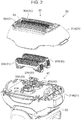
- FIG. 1 is a perspective view of the appearance of an electric shaver according to an embodiment.
- electric shaver 1 includes body 10, head 20 for shaving hair, and head supporting part 50 connecting body 10 with head 20.
- Body 10 includes grip 11, power switch 12 for switching power between on and off, and power supply unit 13 (refer to FIG. 6 ) supplying power to drive source 22 (refer to FIG. 6 ).
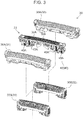
- FIG. 2 illustrates the internal structure of head 20 according to the embodiment.
- Head 20 includes head case 21 forming the outer shell, multiple blade blocks 30, drive source 22 (refer to FIG. 6 ) driving multiple blade blocks 30, and multiple transmission mechanisms 23 connecting drive source 22 with multiple blade blocks 30.
- Head case 21 includes top head case 21A in which multiple blade blocks 30 are provided, and bottom head case 21B containing drive source 22. Head case 21 is composed of top head case 21A and bottom head case 21B joined together.
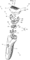
- FIG. 3 illustrates multiple blade blocks 30 according to the embodiment.
- multiple blade blocks 30 include first blade block 31, second blade block 32, and third blade block 33.
- Each of these blade blocks is a set of outer blade 30A and inner blade 30B and is disposed in the transverse direction of head 20 (refer to FIG. 2 ).
- Outer blade 30A is supported by top head case 21A movably up and down with respect to top head case 21A (refer to FIG. 2 ).
- Inner blade 30B is attached to transmission mechanism 23 (refer to FIG. 2 ).
- First blade block 31 is disposed near the front of head 20.
- Second blade block 32 is disposed near the back of head 20.
- Third blade block 33 is disposed between first blade block 31 and second blade block 32.
- Outer blade 30A and inner blade 30B have an elongate shape.
- the longitudinal direction of first blade block 31 through third blade block 33 which is the longitudinal direction of outer blade 30A and inner blade 30B, runs along the longitudinal direction of head 20.
- drive source 22 is a linear motor and is provided with transmission mechanisms 23A and 23B that transmit reciprocating motion of the linear motor to first blade block 31 and second blade block 32, respectively, as shown in FIG. 2 .
- Transmission mechanisms 23A and 23B project earlier than bottom head case 21B.
- Transmission mechanism 23A has inner blade 30B of first blade block 31 and inner blade 30B of third blade block 33 each attached thereto.
- Transmission mechanism 23B has inner blade 30B of second blade block 32 each attached thereto.
- transmission mechanisms 23A and 23B move reciprocatingly in the longitudinal direction of head 20.
- the reciprocating motions of transmission mechanisms 23A and 23B have phases opposite to each other.
- inner blade 30B of first blade block 31 and inner blade 30B of third blade block 33 always move in the direction opposite to inner blade 30B of second blade block 32.
- Head 20 further includes multiple blade float parts 40.
- Blade float parts 40 support first blade block 31 through third blade block 33 so that they are movable up and down with respect to top head case 21A.
- multiple blade float parts 40 include first blade float part 41, second blade float part 42, and third blade float part 43 (refer to FIG. 3 ).
- First blade float part 41 formed in transmission mechanism 23A, includes elastic material 41A provided to exert a reactive force that brings inner blade 30B of first blade block 31 close to outer blade 30A, on inner blade 30B.
- elastic material 41A is a coil spring.
- first blade block 31 moves toward body 10 with respect to top head case 21A while compressing elastic material 41A.
- first blade block 31 moves in the direction opposite to body 10 with respect to top head case 21A due to a reactive force of elastic material 41A.
- Second blade float part 42 formed in transmission mechanism 23B, includes elastic material 42A provided to exert a reactive force that brings inner blade 30B of second blade block 32 close to outer blade 30A, on inner blade 30B.
- elastic material 42A is a coil spring.
- Second blade block 32 when supported by second blade float part 42, acts in the same way as first blade block 31 with respect to top head case 21A.
- third blade float part 43 formed in third blade block 33, includes multiple elastic materials 43A provided to exert a reactive force on third blade block 33.
- elastic material 43A is a coil spring.
- Elastic materials 41A, 42A, and 43A have the same elastic modulus for example.
- FIG. 4 is an exploded perspective view of the configuration of electric shaver 1.
- head supporting part 50 includes swing supporting part 60 supporting head 20 so that head 20 is swingable about the two swing axes; and head float part 70 supporting head 20 so that head 20 is movable up and down with respect to body 10.
- Swing supporting part 60 includes first supporting part 61 forming first swing axis XA (refer to FIG. 5 ) that is one of the two swing axes! and second supporting part 65 forming second swing axis XB (refer to FIG. 5 ) that is the other of the two swing axes.
- First swing axis XA is a swing axis extending in the longitudinal direction of head 20.
- Second swing axis XB is a swing axis extending in the transverse direction of head 20.
- Head 20 is attached to first supporting part 61 so that head 20 is swingable about first swing axis XA with respect to first supporting part 61. Head 20, when swinging about first swing axis XA, swings lengthwise with respect to body 10.
- First supporting part 61 is attached to second supporting part 65 so that first supporting part 61 is swingable about second swing axis XB with respect to second supporting part 65.
- First supporting part 61 when swinging about second swing axis XB, swings crosswise with respect to body 10.
- first supporting part 61 includes first supporting body 62 connected with second supporting part 65; and a pair of first support arms 63 attached to both longitudinal ends of first supporting body 62.
- First supporting part 61 further includes two pairs of second support arms 64 each pair rotatably connected to the pair of first support arms 63.
- Head 20 is rotatably attached to four second support arms 64.
- First swing axis XA is a swing axis of 4-node link mechanism composed of first support arm 63 and second support arm 64.
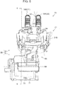
- FIG. 5 is a side view of head 20 with top head case 21A omitted.
- FIG. 6 is a sectional view of the internal structure of head 20 taken along line 6-6 of FIG. 5 .
- the virtual lines (indicated with dashed-dotted lines) each extending in the longitudinal directions of the pair of second support arms 64 attached to one of first support arms 63 form an intersection point.
- First swing axis XA passes through these two intersection points.
- first swing axis XA is formed closer to multiple blade blocks 30 than from head float part 70.
- second supporting part 65 includes second supporting body 66 joined with head float part 70, a pair of pins 67 projecting in the lengthwise directions of second supporting body 66, and a pair of springs 68 (refer to FIG. 6 ) assisting head 20 swinging about second swing axis XB.
- the pair of pins 67 forms second swing axis XB.
- second swing axis XB is formed closer to multiple blade blocks 30 than from head float part 70.
- First supporting body 62 is attached to the pair of pins 67 swingably with respect to second supporting body 66. First supporting body 62, when swinging about the pair of pin 67, swings about second swing axis XB.
- the pair of springs 68 is disposed between first supporting body 62 and second supporting body 66.
- One of springs 68 exerts a force encouraging first supporting body 62 to swing in one direction about second swing axis XB, on first supporting body 62.
- the other of springs 68 exerts a force encouraging first supporting body 62 to swing in the other direction about second swing axis XB, on first supporting body 62.
- Head float part 70 includes case 71 joined with body 10 (refer to FIG. 4 ); and at least one elastic material 72 exerting a force on head 20 (refer to FIG. 4 ) to lift up head 20 off body 10.
- elastic material 72 is formed of two coil springs.
- Second supporting body 66 is supported by case 71 so as to be slidable up and down with respect to case 71.
- Each of elastic materials 72 is disposed between second supporting body 66 and case 71 and exerts a force pressing second supporting body 66 in the direction opposite to body 10, on second supporting body 66.
- second supporting body 66 moves together with head 20 toward body 10 with respect to case 71 while compressing elastic material 72. With the pressing force exerted on head 20 decreasing, second supporting body 66 moves together with head 20 in the direction opposite to body 10 with respect to case 71.
- the force of head float part 70, to lift up head 20 off body 10, exerting on head 20 is greater than the force of blade float part 40, to lift up blade block 30 off head case 21 (refer to FIG. 4 ), exerting on blade block 30.
- the force of head float part 70, to lift up head 20 off body 10, exerting on head 20 is smaller than the total force of each of multiple blade float parts 40, to lift up multiple blade blocks 30 off head case 21, exerting on corresponding blade block 30.
- electric shaver 1 (refer to FIG. 1 ) further includes lead wire 80 connecting drive source 22 with power supply unit 13.
- Power supply unit 13 includes a power source (e.g., a battery, illustration omitted) for drive source 22, a converter (illustration omitted) converting AC power to DC power, and a drive circuit (illustration omitted) for driving drive source 22.
- Lead wire 80 connects drive source 22 with the drive circuit for power supply unit 13. Lead wire 80 is linearly routed through wiring path 51 formed in head supporting part 50. As shown in FIG. 7 , the length of wiring path 51 in the transverse direction of head 20 is longer than that in the longitudinal direction of head 20.
- drive source 22 When the power is turned on by operation of power switch 12 (refer to FIG. 1 ), drive source 22 (refer to FIG. 6 ) is activated. Inner blades 30B (refer to FIG. 2 ) of multiple blade blocks 30 are driven by drive source 22 and reciprocatingly move with respect to outer blades 30A (refer to FIG. 2 ).
- multiple blade blocks 30 performs shaving. At this moment, head 20 swings about at least one of first swing axis XA and second swing axis XB according to undulations of the skin. Resultingly, head 20 moves on the skin while changing the angle with respect to body 10 following undulations of the skin.
- outer blade 30A i.e., one of multiple blade blocks 30, refer to FIG. 2
- first blade block 31 or second blade block 32 onto beneath the nose.
- first blade block 31 or second blade block 32 sinks earlier than head case 21. If head 20 is more strongly pressed against the skin, head 20 sinks with respect to body 10.
- Electric shaver 1 according to the aspect provides the following advantages for example.
- An electric shaver according to the disclosure can take a form of the following modified examples or a form produced from a combination of at least two modified examples compatible with each other.
Landscapes
- Life Sciences & Earth Sciences (AREA)
- Forests & Forestry (AREA)
- Engineering & Computer Science (AREA)
- Mechanical Engineering (AREA)
- Dry Shavers And Clippers (AREA)
Applications Claiming Priority (1)
| Application Number | Priority Date | Filing Date | Title |
|---|---|---|---|
| JP2014241805A JP6376468B2 (ja) | 2014-11-28 | 2014-11-28 | 電気かみそり |
Publications (2)
| Publication Number | Publication Date |
|---|---|
| EP3025832A1 EP3025832A1 (en) | 2016-06-01 |
| EP3025832B1 true EP3025832B1 (en) | 2020-05-27 |
Family
ID=54478655
Family Applications (1)
| Application Number | Title | Priority Date | Filing Date |
|---|---|---|---|
| EP15193815.6A Active EP3025832B1 (en) | 2014-11-28 | 2015-11-10 | Electric shaver |
Country Status (4)
| Country | Link |
|---|---|
| US (1) | US10071490B2 (zh) |
| EP (1) | EP3025832B1 (zh) |
| JP (1) | JP6376468B2 (zh) |
| CN (1) | CN105643671B (zh) |
Families Citing this family (11)
| Publication number | Priority date | Publication date | Assignee | Title |
|---|---|---|---|---|
| JP6376468B2 (ja) * | 2014-11-28 | 2018-08-22 | パナソニックIpマネジメント株式会社 | 電気かみそり |
| USD823543S1 (en) * | 2015-12-11 | 2018-07-17 | Koninklijke Philips N.V. | Beard trimmer |
| TWD182600S (zh) * | 2015-12-11 | 2017-04-21 | 皇家飛利浦有限公司 | 修鬍器 |
| EP3300844B1 (en) * | 2016-09-28 | 2020-04-15 | Braun GmbH | Electric shaver |
| EP3300854B1 (en) | 2016-09-28 | 2020-06-10 | Braun GmbH | Electric shaver |
| EP3300861B1 (en) | 2016-09-28 | 2019-07-03 | Braun GmbH | Electrically driven device |
| EP3403778B1 (en) | 2017-05-17 | 2020-01-01 | Panasonic Intellectual Property Management Co., Ltd. | Hair cutting device |
| JP1654722S (ja) * | 2019-08-26 | 2020-03-09 | 電気かみそり | |
| JP2022155347A (ja) * | 2021-03-30 | 2022-10-13 | パナソニックIpマネジメント株式会社 | 電気かみそり |
| JP2022155367A (ja) | 2021-03-30 | 2022-10-13 | パナソニックIpマネジメント株式会社 | 電気かみそり |
| JP1739358S (zh) * | 2022-07-01 | 2023-03-20 |
Citations (1)
| Publication number | Priority date | Publication date | Assignee | Title |
|---|---|---|---|---|
| EP1935585A1 (en) * | 2005-09-27 | 2008-06-25 | Matsushita Electric Works, Ltd. | Electric shaver |
Family Cites Families (22)
| Publication number | Priority date | Publication date | Assignee | Title |
|---|---|---|---|---|
| JP3201689B2 (ja) * | 1994-01-10 | 2001-08-27 | 松下電工株式会社 | 往復式電気かみそり |
| JP3979052B2 (ja) * | 2001-09-25 | 2007-09-19 | 松下電工株式会社 | 往復式電気かみそり |
| JP3826876B2 (ja) * | 2001-11-15 | 2006-09-27 | 松下電工株式会社 | 電気かみそり |
| DE60206070T2 (de) * | 2001-11-15 | 2006-06-14 | Matsushita Electric Works Ltd | Trockenrasierer mit schwenkbarem kopf |
| CN1284656C (zh) * | 2002-06-17 | 2006-11-15 | 松下电工株式会社 | 具有修剪器的干式剃须刀 |
| KR100563481B1 (ko) * | 2002-06-17 | 2006-03-27 | 마츠시다 덴코 가부시키가이샤 | 전기면도기의 가동헤드 유지구조 |
| JP2005040358A (ja) * | 2003-07-22 | 2005-02-17 | Matsushita Electric Works Ltd | シェーバー |
| JP3972903B2 (ja) * | 2003-12-26 | 2007-09-05 | 松下電工株式会社 | 電気かみそり |
| JP4604846B2 (ja) * | 2005-05-31 | 2011-01-05 | パナソニック電工株式会社 | 体毛処理器具 |
| DE102006030947A1 (de) * | 2006-07-05 | 2008-01-10 | Braun Gmbh | Elektrischer Trockenrasierapparat |
| US20080034591A1 (en) * | 2006-08-08 | 2008-02-14 | Kam Fai Fung | Shaver with swivel head |
| JP4969946B2 (ja) * | 2006-08-11 | 2012-07-04 | 株式会社泉精器製作所 | 往復式電気かみそり |
| JP4207080B2 (ja) * | 2006-12-08 | 2009-01-14 | パナソニック電工株式会社 | 電気かみそり |
| DE102008031132A1 (de) * | 2008-07-01 | 2010-01-07 | Braun Gmbh | Elektrisches Kleingerät zum Entfernen von Haaren |
| CN101428422A (zh) * | 2008-12-08 | 2009-05-13 | 陈炯芳 | 一种剃须器的头部浮动结构 |
| JP4955711B2 (ja) | 2009-01-15 | 2012-06-20 | パナソニック株式会社 | 電気かみそり |
| JP4988777B2 (ja) * | 2009-01-15 | 2012-08-01 | パナソニック株式会社 | 電気かみそり |
| JP4840450B2 (ja) * | 2009-01-16 | 2011-12-21 | パナソニック電工株式会社 | 電気かみそり |
| US9527219B2 (en) * | 2009-09-25 | 2016-12-27 | Panasonic Intellectual Property Management Co., Ltd. | Electric shaver |
| CN101890730A (zh) * | 2010-07-09 | 2010-11-24 | 美的集团有限公司 | 全方位浮动的旋转式剃须刀 |
| JP5842158B2 (ja) * | 2011-02-28 | 2016-01-13 | パナソニックIpマネジメント株式会社 | 電気かみそり |
| JP6376468B2 (ja) * | 2014-11-28 | 2018-08-22 | パナソニックIpマネジメント株式会社 | 電気かみそり |
-
2014
- 2014-11-28 JP JP2014241805A patent/JP6376468B2/ja active Active
-
2015
- 2015-11-10 EP EP15193815.6A patent/EP3025832B1/en active Active
- 2015-11-12 US US14/939,746 patent/US10071490B2/en active Active
- 2015-11-27 CN CN201510850115.4A patent/CN105643671B/zh active Active
Patent Citations (1)
| Publication number | Priority date | Publication date | Assignee | Title |
|---|---|---|---|---|
| EP1935585A1 (en) * | 2005-09-27 | 2008-06-25 | Matsushita Electric Works, Ltd. | Electric shaver |
Also Published As
| Publication number | Publication date |
|---|---|
| CN105643671B (zh) | 2019-04-23 |
| JP2016101366A (ja) | 2016-06-02 |
| JP6376468B2 (ja) | 2018-08-22 |
| US20160151922A1 (en) | 2016-06-02 |
| CN105643671A (zh) | 2016-06-08 |
| EP3025832A1 (en) | 2016-06-01 |
| US10071490B2 (en) | 2018-09-11 |
Similar Documents
| Publication | Publication Date | Title |
|---|---|---|
| EP3025832B1 (en) | Electric shaver | |
| CN201143690Y (zh) | 剪发器 | |
| RU2700884C2 (ru) | Режущая головка и устройство для стрижки волос | |
| JP6321804B2 (ja) | 取付けユニット及び毛切断器具 | |
| RU2415746C1 (ru) | Электробритва | |
| JP4148186B2 (ja) | 往復直線運動を行う被駆動部材を備えたヘッド部が本体部に対して揺動可能な電動器具 | |
| KR20120115259A (ko) | 피봇팅 기구를 구비한 모발 절단 장치 | |
| JP4337634B2 (ja) | 往復直線運動を行う被駆動部材を備えたヘッド部が本体部に対して揺動可能な電動器具 | |
| KR20080035020A (ko) | 전기면도기 | |
| WO2011037126A1 (ja) | 電気かみそり | |
| JP2006167213A (ja) | 除毛装置 | |
| US20180085948A1 (en) | Electrically-driven razor | |
| CN105936052B (zh) | 电动剃刀及其头部 | |
| JP5842158B2 (ja) | 電気かみそり | |
| JP6931804B2 (ja) | 体毛処理機 | |
| JP6695045B2 (ja) | 電気式毛切断装置 | |
| JP6741971B2 (ja) | 電気かみそり | |
| JP5879531B2 (ja) | 電気かみそり | |
| WO2011037059A1 (ja) | 電気かみそり | |
| JP6052542B2 (ja) | スリット刃ブロックおよび刃ユニットならびに電気かみそり | |
| JP3211242U (ja) | バリカン | |
| JP2017213114A (ja) | 電気かみそり | |
| KR200214254Y1 (ko) | 전기면도기 | |
| JP2014235864A (ja) | スライドスイッチ装置 | |
| CN110181563A (zh) | 一种剃须刀头 |
Legal Events
| Date | Code | Title | Description |
|---|---|---|---|
| PUAI | Public reference made under article 153(3) epc to a published international application that has entered the european phase |
Free format text: ORIGINAL CODE: 0009012 |
|
| AK | Designated contracting states |
Kind code of ref document: A1 Designated state(s): AL AT BE BG CH CY CZ DE DK EE ES FI FR GB GR HR HU IE IS IT LI LT LU LV MC MK MT NL NO PL PT RO RS SE SI SK SM TR |
|
| AX | Request for extension of the european patent |
Extension state: BA ME |
|
| STAA | Information on the status of an ep patent application or granted ep patent |
Free format text: STATUS: REQUEST FOR EXAMINATION WAS MADE |
|
| 17P | Request for examination filed |
Effective date: 20161121 |
|
| RBV | Designated contracting states (corrected) |
Designated state(s): AL AT BE BG CH CY CZ DE DK EE ES FI FR GB GR HR HU IE IS IT LI LT LU LV MC MK MT NL NO PL PT RO RS SE SI SK SM TR |
|
| STAA | Information on the status of an ep patent application or granted ep patent |
Free format text: STATUS: EXAMINATION IS IN PROGRESS |
|
| 17Q | First examination report despatched |
Effective date: 20181127 |
|
| GRAP | Despatch of communication of intention to grant a patent |
Free format text: ORIGINAL CODE: EPIDOSNIGR1 |
|
| STAA | Information on the status of an ep patent application or granted ep patent |
Free format text: STATUS: GRANT OF PATENT IS INTENDED |
|
| INTG | Intention to grant announced |
Effective date: 20200207 |
|
| GRAS | Grant fee paid |
Free format text: ORIGINAL CODE: EPIDOSNIGR3 |
|
| GRAA | (expected) grant |
Free format text: ORIGINAL CODE: 0009210 |
|
| STAA | Information on the status of an ep patent application or granted ep patent |
Free format text: STATUS: THE PATENT HAS BEEN GRANTED |
|
| AK | Designated contracting states |
Kind code of ref document: B1 Designated state(s): AL AT BE BG CH CY CZ DE DK EE ES FI FR GB GR HR HU IE IS IT LI LT LU LV MC MK MT NL NO PL PT RO RS SE SI SK SM TR |
|
| REG | Reference to a national code |
Ref country code: GB Ref legal event code: FG4D |
|
| REG | Reference to a national code |
Ref country code: CH Ref legal event code: EP |
|
| REG | Reference to a national code |
Ref country code: AT Ref legal event code: REF Ref document number: 1274093 Country of ref document: AT Kind code of ref document: T Effective date: 20200615 |
|
| REG | Reference to a national code |
Ref country code: DE Ref legal event code: R096 Ref document number: 602015053279 Country of ref document: DE |
|
| REG | Reference to a national code |
Ref country code: LT Ref legal event code: MG4D |
|
| PG25 | Lapsed in a contracting state [announced via postgrant information from national office to epo] |
Ref country code: LT Free format text: LAPSE BECAUSE OF FAILURE TO SUBMIT A TRANSLATION OF THE DESCRIPTION OR TO PAY THE FEE WITHIN THE PRESCRIBED TIME-LIMIT Effective date: 20200527 Ref country code: FI Free format text: LAPSE BECAUSE OF FAILURE TO SUBMIT A TRANSLATION OF THE DESCRIPTION OR TO PAY THE FEE WITHIN THE PRESCRIBED TIME-LIMIT Effective date: 20200527 Ref country code: SE Free format text: LAPSE BECAUSE OF FAILURE TO SUBMIT A TRANSLATION OF THE DESCRIPTION OR TO PAY THE FEE WITHIN THE PRESCRIBED TIME-LIMIT Effective date: 20200527 Ref country code: IS Free format text: LAPSE BECAUSE OF FAILURE TO SUBMIT A TRANSLATION OF THE DESCRIPTION OR TO PAY THE FEE WITHIN THE PRESCRIBED TIME-LIMIT Effective date: 20200927 Ref country code: GR Free format text: LAPSE BECAUSE OF FAILURE TO SUBMIT A TRANSLATION OF THE DESCRIPTION OR TO PAY THE FEE WITHIN THE PRESCRIBED TIME-LIMIT Effective date: 20200828 Ref country code: NO Free format text: LAPSE BECAUSE OF FAILURE TO SUBMIT A TRANSLATION OF THE DESCRIPTION OR TO PAY THE FEE WITHIN THE PRESCRIBED TIME-LIMIT Effective date: 20200827 Ref country code: PT Free format text: LAPSE BECAUSE OF FAILURE TO SUBMIT A TRANSLATION OF THE DESCRIPTION OR TO PAY THE FEE WITHIN THE PRESCRIBED TIME-LIMIT Effective date: 20200928 |
|
| REG | Reference to a national code |
Ref country code: NL Ref legal event code: MP Effective date: 20200527 |
|
| PG25 | Lapsed in a contracting state [announced via postgrant information from national office to epo] |
Ref country code: HR Free format text: LAPSE BECAUSE OF FAILURE TO SUBMIT A TRANSLATION OF THE DESCRIPTION OR TO PAY THE FEE WITHIN THE PRESCRIBED TIME-LIMIT Effective date: 20200527 Ref country code: BG Free format text: LAPSE BECAUSE OF FAILURE TO SUBMIT A TRANSLATION OF THE DESCRIPTION OR TO PAY THE FEE WITHIN THE PRESCRIBED TIME-LIMIT Effective date: 20200827 Ref country code: RS Free format text: LAPSE BECAUSE OF FAILURE TO SUBMIT A TRANSLATION OF THE DESCRIPTION OR TO PAY THE FEE WITHIN THE PRESCRIBED TIME-LIMIT Effective date: 20200527 Ref country code: LV Free format text: LAPSE BECAUSE OF FAILURE TO SUBMIT A TRANSLATION OF THE DESCRIPTION OR TO PAY THE FEE WITHIN THE PRESCRIBED TIME-LIMIT Effective date: 20200527 |
|
| REG | Reference to a national code |
Ref country code: AT Ref legal event code: MK05 Ref document number: 1274093 Country of ref document: AT Kind code of ref document: T Effective date: 20200527 |
|
| PG25 | Lapsed in a contracting state [announced via postgrant information from national office to epo] |
Ref country code: NL Free format text: LAPSE BECAUSE OF FAILURE TO SUBMIT A TRANSLATION OF THE DESCRIPTION OR TO PAY THE FEE WITHIN THE PRESCRIBED TIME-LIMIT Effective date: 20200527 Ref country code: AL Free format text: LAPSE BECAUSE OF FAILURE TO SUBMIT A TRANSLATION OF THE DESCRIPTION OR TO PAY THE FEE WITHIN THE PRESCRIBED TIME-LIMIT Effective date: 20200527 |
|
| PG25 | Lapsed in a contracting state [announced via postgrant information from national office to epo] |
Ref country code: ES Free format text: LAPSE BECAUSE OF FAILURE TO SUBMIT A TRANSLATION OF THE DESCRIPTION OR TO PAY THE FEE WITHIN THE PRESCRIBED TIME-LIMIT Effective date: 20200527 Ref country code: DK Free format text: LAPSE BECAUSE OF FAILURE TO SUBMIT A TRANSLATION OF THE DESCRIPTION OR TO PAY THE FEE WITHIN THE PRESCRIBED TIME-LIMIT Effective date: 20200527 Ref country code: SM Free format text: LAPSE BECAUSE OF FAILURE TO SUBMIT A TRANSLATION OF THE DESCRIPTION OR TO PAY THE FEE WITHIN THE PRESCRIBED TIME-LIMIT Effective date: 20200527 Ref country code: EE Free format text: LAPSE BECAUSE OF FAILURE TO SUBMIT A TRANSLATION OF THE DESCRIPTION OR TO PAY THE FEE WITHIN THE PRESCRIBED TIME-LIMIT Effective date: 20200527 Ref country code: IT Free format text: LAPSE BECAUSE OF FAILURE TO SUBMIT A TRANSLATION OF THE DESCRIPTION OR TO PAY THE FEE WITHIN THE PRESCRIBED TIME-LIMIT Effective date: 20200527 Ref country code: AT Free format text: LAPSE BECAUSE OF FAILURE TO SUBMIT A TRANSLATION OF THE DESCRIPTION OR TO PAY THE FEE WITHIN THE PRESCRIBED TIME-LIMIT Effective date: 20200527 Ref country code: CZ Free format text: LAPSE BECAUSE OF FAILURE TO SUBMIT A TRANSLATION OF THE DESCRIPTION OR TO PAY THE FEE WITHIN THE PRESCRIBED TIME-LIMIT Effective date: 20200527 Ref country code: RO Free format text: LAPSE BECAUSE OF FAILURE TO SUBMIT A TRANSLATION OF THE DESCRIPTION OR TO PAY THE FEE WITHIN THE PRESCRIBED TIME-LIMIT Effective date: 20200527 |
|
| PG25 | Lapsed in a contracting state [announced via postgrant information from national office to epo] |
Ref country code: PL Free format text: LAPSE BECAUSE OF FAILURE TO SUBMIT A TRANSLATION OF THE DESCRIPTION OR TO PAY THE FEE WITHIN THE PRESCRIBED TIME-LIMIT Effective date: 20200527 Ref country code: SK Free format text: LAPSE BECAUSE OF FAILURE TO SUBMIT A TRANSLATION OF THE DESCRIPTION OR TO PAY THE FEE WITHIN THE PRESCRIBED TIME-LIMIT Effective date: 20200527 |
|
| REG | Reference to a national code |
Ref country code: DE Ref legal event code: R097 Ref document number: 602015053279 Country of ref document: DE |
|
| PLBE | No opposition filed within time limit |
Free format text: ORIGINAL CODE: 0009261 |
|
| STAA | Information on the status of an ep patent application or granted ep patent |
Free format text: STATUS: NO OPPOSITION FILED WITHIN TIME LIMIT |
|
| 26N | No opposition filed |
Effective date: 20210302 |
|
| PG25 | Lapsed in a contracting state [announced via postgrant information from national office to epo] |
Ref country code: SI Free format text: LAPSE BECAUSE OF FAILURE TO SUBMIT A TRANSLATION OF THE DESCRIPTION OR TO PAY THE FEE WITHIN THE PRESCRIBED TIME-LIMIT Effective date: 20200527 |
|
| PG25 | Lapsed in a contracting state [announced via postgrant information from national office to epo] |
Ref country code: MC Free format text: LAPSE BECAUSE OF FAILURE TO SUBMIT A TRANSLATION OF THE DESCRIPTION OR TO PAY THE FEE WITHIN THE PRESCRIBED TIME-LIMIT Effective date: 20200527 |
|
| REG | Reference to a national code |
Ref country code: CH Ref legal event code: PL |
|
| GBPC | Gb: european patent ceased through non-payment of renewal fee |
Effective date: 20201110 |
|
| PG25 | Lapsed in a contracting state [announced via postgrant information from national office to epo] |
Ref country code: LU Free format text: LAPSE BECAUSE OF NON-PAYMENT OF DUE FEES Effective date: 20201110 |
|
| REG | Reference to a national code |
Ref country code: BE Ref legal event code: MM Effective date: 20201130 |
|
| PG25 | Lapsed in a contracting state [announced via postgrant information from national office to epo] |
Ref country code: LI Free format text: LAPSE BECAUSE OF NON-PAYMENT OF DUE FEES Effective date: 20201130 Ref country code: CH Free format text: LAPSE BECAUSE OF NON-PAYMENT OF DUE FEES Effective date: 20201130 |
|
| PG25 | Lapsed in a contracting state [announced via postgrant information from national office to epo] |
Ref country code: FR Free format text: LAPSE BECAUSE OF NON-PAYMENT OF DUE FEES Effective date: 20201130 Ref country code: IE Free format text: LAPSE BECAUSE OF NON-PAYMENT OF DUE FEES Effective date: 20201110 |
|
| PG25 | Lapsed in a contracting state [announced via postgrant information from national office to epo] |
Ref country code: GB Free format text: LAPSE BECAUSE OF NON-PAYMENT OF DUE FEES Effective date: 20201110 |
|
| PG25 | Lapsed in a contracting state [announced via postgrant information from national office to epo] |
Ref country code: TR Free format text: LAPSE BECAUSE OF FAILURE TO SUBMIT A TRANSLATION OF THE DESCRIPTION OR TO PAY THE FEE WITHIN THE PRESCRIBED TIME-LIMIT Effective date: 20200527 Ref country code: MT Free format text: LAPSE BECAUSE OF FAILURE TO SUBMIT A TRANSLATION OF THE DESCRIPTION OR TO PAY THE FEE WITHIN THE PRESCRIBED TIME-LIMIT Effective date: 20200527 Ref country code: CY Free format text: LAPSE BECAUSE OF FAILURE TO SUBMIT A TRANSLATION OF THE DESCRIPTION OR TO PAY THE FEE WITHIN THE PRESCRIBED TIME-LIMIT Effective date: 20200527 |
|
| PG25 | Lapsed in a contracting state [announced via postgrant information from national office to epo] |
Ref country code: MK Free format text: LAPSE BECAUSE OF FAILURE TO SUBMIT A TRANSLATION OF THE DESCRIPTION OR TO PAY THE FEE WITHIN THE PRESCRIBED TIME-LIMIT Effective date: 20200527 |
|
| PG25 | Lapsed in a contracting state [announced via postgrant information from national office to epo] |
Ref country code: BE Free format text: LAPSE BECAUSE OF NON-PAYMENT OF DUE FEES Effective date: 20201130 |
|
| PGFP | Annual fee paid to national office [announced via postgrant information from national office to epo] |
Ref country code: DE Payment date: 20230420 Year of fee payment: 9 |