EP3022134B2 - Verfahren zur auftragserfüllung durch bereitstellung von lagereinheiten in einer kommissionierstation - Google Patents
Verfahren zur auftragserfüllung durch bereitstellung von lagereinheiten in einer kommissionierstation Download PDFInfo
- Publication number
- EP3022134B2 EP3022134B2 EP14734154.9A EP14734154A EP3022134B2 EP 3022134 B2 EP3022134 B2 EP 3022134B2 EP 14734154 A EP14734154 A EP 14734154A EP 3022134 B2 EP3022134 B2 EP 3022134B2
- Authority
- EP
- European Patent Office
- Prior art keywords
- storage
- conveyor
- picking
- lift
- level
- Prior art date
- Legal status (The legal status is an assumption and is not a legal conclusion. Google has not performed a legal analysis and makes no representation as to the accuracy of the status listed.)
- Active
Links
Images


Classifications
-
- B—PERFORMING OPERATIONS; TRANSPORTING
- B65—CONVEYING; PACKING; STORING; HANDLING THIN OR FILAMENTARY MATERIAL
- B65G—TRANSPORT OR STORAGE DEVICES, e.g. CONVEYORS FOR LOADING OR TIPPING, SHOP CONVEYOR SYSTEMS OR PNEUMATIC TUBE CONVEYORS
- B65G1/00—Storing articles, individually or in orderly arrangement, in warehouses or magazines
- B65G1/02—Storage devices
- B65G1/04—Storage devices mechanical
- B65G1/137—Storage devices mechanical with arrangements or automatic control means for selecting which articles are to be removed
- B65G1/1373—Storage devices mechanical with arrangements or automatic control means for selecting which articles are to be removed for fulfilling orders in warehouses
- B65G1/1378—Storage devices mechanical with arrangements or automatic control means for selecting which articles are to be removed for fulfilling orders in warehouses the orders being assembled on fixed commissioning areas remote from the storage areas
-
- B—PERFORMING OPERATIONS; TRANSPORTING
- B65—CONVEYING; PACKING; STORING; HANDLING THIN OR FILAMENTARY MATERIAL
- B65G—TRANSPORT OR STORAGE DEVICES, e.g. CONVEYORS FOR LOADING OR TIPPING, SHOP CONVEYOR SYSTEMS OR PNEUMATIC TUBE CONVEYORS
- B65G1/00—Storing articles, individually or in orderly arrangement, in warehouses or magazines
- B65G1/02—Storage devices
- B65G1/04—Storage devices mechanical
- B65G1/06—Storage devices mechanical with means for presenting articles for removal at predetermined position or level
Definitions
- the invention relates to a method of order fulfilling in accordance with the preamble of claim 1.
- the goods for fulfilling an order are taken from the transporting or storage units and placed according to the order into an order container etc.
- the storage container (often called donor) is then routed back into the racking storage and stored until needed for the next order.
- a (high bay) racking storage facility includes a storage-entry area, via which the goods are supplied to and from which the Automatic Storage and Retrieval Machine (hereafter called AS/RS) collects the goods for placement in storage, the so-called front-zone.
- AS/RS Automatic Storage and Retrieval Machine
- a retrieval area is required, at which after retrieval from storage the AS/RS deposit the goods which are likewise assigned to the front-zone.
- picking locations are typically situated in the front-zone.
- the goods are also identified for the inventory management system or the material flow computer.
- EP 1 964 792 B1 by the present applicant discloses a method of making transporting units available from a storage facility on at least one collecting line.
- AS/RS in each storage racking aisle, retrieval-from-storage and outbound lines are controlled, in such a way as to be matched and coordinated to one another, and are loaded with goods that ultimately they end up on, or are discharged from, the collecting line in a sorted fashion.
- control and matching are thus relatively complex and require evident technical work in the so-called front-zone, i.e. the area outside the actual racking, is necessary to achieve high trough put and sequencing.
- Document DE 102 34 150 A1 discloses a method of order fulfilling according to the preamble of claim 1.
- the object of the invention is to provide a method of order fulfilling, which provides sorted retrieval from storage in a simpler manner and without sortation outside of the aisles. This reduces technical complexity and space, lowers cost and achieves better reliability and throughput.
- the picking stations can be manual operated and either semi- or fully automated order picking stations.
- a fully automated picking station is defined as a picking station according to the goods-to-person principle with fully automated unit (totes, container, trays, boxes etc.) handling, i.e. a fully automated supply and discharge and presentation of the product and order units. Empty order units and/or units with commissioning goods are automatically supplied to the work station. Units are placed in ergonomically optimal height on the picking station. Usually such a station will also incorporate means for directing, instructing and controlling as well as supervising the picker (e.g. pick-to-light, optical pointing device, IT display etc.), who will still manually pick out of product units into order units. In contrast a semiautomatic picking station will not have the fully automated unit handling just described, but will involve some manual processing of units.
- the picking stations may be orientated such that they face each other and lifts are located between them. It is also possible that two picking stations are connected to two lifts on a single level.
- a picking station may have temporary shelving, e.g. for pre-picking certain articles
- the automatic storage and retrieval device is fed by an inbound-buffer-conveyor and/or feeds into an outbound-buffer-conveyor, wherein the buffers are arranged within the racking unit. This allows for high performance due to quick relief of the AS/RS.
- outbound-buffer feeds into the conveyor loop and inbound-buffer is fed by the conveyor loop, in particular in the picking level.
- the conveyor loop may also contain a junction or switch as an option to selectively feed the inbound-buffer, so that storage units coming from the picking station via the storage-entry feeding line passing through the lift can be conveyed to the inbound-buffer, or, in other words, pass through the loop.
- the at least one lift is arranged in one of the pair of racking units (racks of an aisle) and is possibly of the drive-through-type, but not limited to, and is fed by the storage-entry feeding line and itself feeds the outbound line of a first conveyor loop in a first picking level, but circumnavigates around a second lift arranged in the other of the pair of racking units, which is also of the drive-through-type, but not limited to, and is fed by the storage-entry feeding line and itself feeds the outbound line of a second conveyor loop in a second picking level, wherein the conveyor loop circumnavigates around the first lift in the second picking level.
- This allows for use of two picking levels that each are only coupled to one lift to achieve high performance.
- the lift is preferably fed by an inbound-buffer and feeds into an outbound-buffer, wherein the buffers are arranged within the racking unit.
- the storage is preferably a fully automated storage.
- storage racking locations of abutting racking units are used for passing transporting or storage units from one side of the racking through to the next, so that the transporting units can be transferred from one racking to the next.
- cross conveyance or sorting is possible inside the racking units themselves and accordingly it is possible to dispense with or at least minimize "cross conveyance" in the front-zone.
- the cross conveyance locations are provided in each level or any selected level of the storage racking units.
- cross conveyance locations are disposed closer to inbound and outbound buffer conveyors. It is also possible to locate cross conveyance locations at different positions within a level.
- the cross conveyance locations can also be used as buffers, especially if they belong to final destination aisle of the transport or storage units, i.e. the transporting or storage units remain therein, until they are actually needed or retrieved.
- the exchange can be effected actively or passively with regard to the AS/RS i.e., on the one hand the cross conveyance location can be simply a passive storage surface, on which the AS/RS of one aisle deposits transporting or storage units (quasi places them into storage) and from which the AS/RS of the adjacent aisle receives transporting units (quasi removes them from storage). For each racking storage location or cross conveyance location this procedure can always be performed in one direction only or in both directions.
- cross conveyance location it is likewise possible to equip the cross conveyance location with corresponding conveyance technology, such as driven rollers, gravity flow track, idler roller, conveyor belts with or without a drive etc.
- the AS/RS can then deposit the transporting or storage units and the conveyance technology of the cross conveyance location performs transportation.
- the cross conveyance locations can also be equipped with a push mechanism for the transporting units.
- cross conveyance locations By reason of the simplicity of the cross conveyance locations it is also possible to subsequently retrofit or refit cross conveyance locations and to adapt flexibly to the level of efficiency required in the storage system.
- the cross conveyance locations can thus optionally be configured for bidirectional or unidirectional exchange and/or for active or passive exchange.
- the AS/RS can likewise place the transporting units in normal storage, double-depth storage or multiple-depth storage in the cross conveyance location.
- the AS/RS of one aisle can thus place the transporting or storage units in storage in the cross conveyance locations to such a depth that they are already to be assigned to the adjacent racking and can be reached "normally" by the AS/RS in the adjacent racking.
- the load receiving means e.g. telescopic arms
- the load receiving means can have an extended range.
- the floors of the cross conveyance locations are subjected to be utilized extensively and reduce a damage of transport or storage unit, it is expedient if the floors of the cross conveyance locations can be coated to reduce friction and/or structural reinforcement can be effected.
- AS/RS are single-level racking serving units.
- shuttles or satellite vehicles are preferred.
- shuttles with a stacked arrangement of two load handling platforms or an elevating platform are to be used in connection with the invention for handling several levels from a single rail.
- the shuttle is decoupled from the at least one lift by an inbound-buffer-conveyor and/or an outbound-buffer-conveyor, wherein the buffer-conveyors are arranged within the racks.
- the outbound-buffer-conveyors and inbound-buffer-conveyors may also be located in a rack or alternatively outside of a rack.
- the outbound-buffers are located in or outside of one rack of an aisle and inbound-buffers are located in or outside the other rack of an aisle.
- the units on a level where the outbound buffer conveyor is missing are always transferred to an adjacent aisle via cross conveyance locations.
- the inbound buffer conveyor is missing units from an adjacent aisle are received via cross conveyance locations.
- outbound-buffer-conveyors and inbound-buffer-conveyors are located on every non-picking level.
- the storage-entry conveyor and the storage-exit conveyor should preferably be arranged in the same level, especially the picking level, i.e. the level in which the picking station is located.
- the storage-entry conveyor and the storage-exit conveyor may be arranged in different levels, so that the picking station is supplied on one level and units are dispatched from it on a second level.
- each storage-entry and/or exit conveyor level has buffer conveyors directly feeding or fed by storage-entry and/or exit conveyors.
- transporting units or likewise “storage units”
- transport units also includes totes, trays, containers, paperboard containers, carton boxes, packaging units, i.e. combined individual articles, etc. and individual articles.
- These units can either be donor units, from which a picker takes articles for an order, so that these function as a donor (often also called product units), or these units can be order units for collecting articles of an order.
- the transporting or storage units can be placed in storage randomly ("chaotically") being distributed over the entire system without knowledge of the subsequent sequence when they are retrieved.
- storage randomly (“chaotically") being distributed over the entire system without knowledge of the subsequent sequence when they are retrieved.
- no restriction as to possible modules or storage areas is required.
- Multishuttles ® are used as the single-level AS/RS.
- the Multishuttle ® is a system which can be used universally, is constructed in a modular fashion and combines storage and transportation in an integrated concept.
- the Multishuttle ® supplements the domain of automatic small parts storage facilities as a high-performance, inexpensive and innovative solution. It is a rail-borne vehicle which operates in the racking and serves the entire storage system.
- the system concept is based upon autonomous rail-guided vehicles for container transportation which operate inside and outside the storage system.
- a specific load receiving means permits short load-change times and simultaneous loading and unloading.
- the system has travel rails which are installed in each level of the storage facility or elevated or suspended in the pre-zone. In addition to guiding the vehicles, they also supply voltage thereto.
- the shuttle can be used in two arrangements, a so called “captive” or “roaming” arrangement.
- the captive arrangement the shuttle stay in their respective level.
- the roaming alternative the shuttle change levels as required.
- Possible outbound lifts include in particular vertical conveying means. It is favorable if each outbound lift has one or more, in particular two, locations/positions for the transporting or storage units.
- each level of the storage racking has at least one buffer location for decoupling the single-level AS/RS and the outbound lift. This renders it possible to fully utilize the quicker single-level AS/RS and to prevent empty-running of the lift.
- Each outbound lift may be connected to several outbound lines. This improves the sorting options and increases the number of orders which can be processed in parallel, or the number of stations which can be supplied.
- the outbound lines are formed as accumulations conveyors. These may include a mechanical device for accumulation, e.g. a movable stop element.
- each outbound lift has a separately driven conveying means for each location.
- each outbound lift has two locations which are each provided with a separately driven conveying means movable in different directions. Therefore, the transfer of two transporting or storage units for each level (e.g. in a previously standing arrangement) can always be effected simultaneously in different directions or onto different outbound buffers, e.g. to the left and right.
- the reception of the transporting units onto the lift is preferably controlled so that the two transporting/storage units are to be discharged onto one level.
- the system is further characterized by a high degree of flexibility, since the inbound and outbound feeding lines can be connected to the corresponding lifts at any points.
- inbound lifts In parallel with the outbound lifts, it is likewise possible to provide dedicated inbound lifts with correspondingly supplying distribution feeding lines. On the other hand, it is also possible to control the outbound lifts such that in addition to the outbound operation they can also be used as inbound lifts. In the reverse scenario, optionally present dedicated inbound lifts can also be used as outbound lifts according to requirement. In the event of malfunctions of individual lifts, this also permits uninterrupted operation or an increase in system efficiency. To this end, the inbound or outbound lines must be disposed between the lift and racking at different heights. This requires the presence of two similar combined inbound and outbound levels, the collecting lines of which are brought together after passing the last outbound line in sequence.
- transverse displacement function by means of the cross conveyance locations within the rack offers the advantage that, in the event of a malfunction of e.g. an outbound lift/inbound lift or feeding lines, the function of the relevant aisle can be maintained.
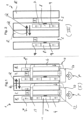
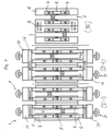
- the Figures 1 and 2 illustrate a storage facility, which is designated as a whole by the reference numeral 1, having a plurality of storage racking aisles 2 and storage racking units R having a plurality of levels 3.
- the storage racking units R are disposed in such a manner that the storage racking units R which are not disposed on the outside are each disposed in pairs adjoining one another and have a storage racking aisle 2 on one side.
- the storage racking units R located on the inside in each case abut one another "back-to-back". Every other storage racking aisle 2 is provided with a lift 8 having at least one or more locations/ positions for storage units T in each case.
- the lift 8 is adjoined by an inbound line 4 and a removal-from-storage feeding line or outbound conveyor 6 or can be configured vice versa.
- Corresponding inbound and outbound buffer conveyors 7* and 9*, provided as an option, are disposed between the lift 8 and the storage racking R in the picking level I, in order to decouple the lift 8 from the single level AS/RS 5 (also referred to as shuttles) which travel in the storage racking aisle 2.
- Lift 8 is of the drive through type, meaning that a storage unit T may either use the lift to change levels or pass through the lift 8, in a conveyor manner, so that it may be conveyed via conveyor 6 and RAT (Right Angle Transfer) 13 to inbound-buffer 7 on the storage level or from the lift 8 conveyed via conveyor 6 to the picking station 10.
- the lift 8 is arranged in one of the pair of racking units R and is fed by the storage-entry feeding line 4 and itself feeds the outbound line 6 in the picking level I.
- the shuttle 5 is fed by an inbound-buffer 7 and feeds into an outbound-buffer 9, wherein both buffers 7, 9 are arranged within the racking unit R directly behind the conveyor loop 11.
- the outbound-buffer 9 feeds into the conveyor loop 11 or outbound line 6 and inbound-buffer 7 is fed by the conveyor loop or outbound line 6 after the lift 8. For this reason the conveyor loop 11 or outbound line 6 contains a junction or switch 13 to selectively feed the inbound-buffer 7.
- each aisle 2 in the picking level I is connected to a picking station 10 by a conveyor loop 11 formed with the storage-entry feeding line 4, the lift 8 and the outbound line 6, to which storage units T are fed for picking for fulfilling orders by the picker P.
- Picking station 10 may include temporary shelves 12 as a temporary store for pre-picking often used articles.
- the shuttles 5 are provided in each storage racking aisle 2 and in each level III. These are thus a so-called “captive” variant, in which the shuttles or satellite vehicles 5 are fixedly allocated to a level 3 and do not change levels or aisles, which theoretically would be possible.
- the shuttles 5 include a transport platform for receiving/carrying the respective storage unit T (paperboard container, tray, totes, container, goods without any loading aids, etc.). Disposed in each case to the side on the transport platform are telescopic arms which push the storage unit T off, or pull it onto, the platform. In addition, the telescopic arms are extendible on both sides of the storage racking aisle 2 into the racking units R and have fingers which can be open and close in a known manner.
- Particular exchange locations Q for cross-conveyance of storage units T from one racking R into the adjacent racking R are provided in each level 3 of the storage racking units R, so that the storage units T are exchanged inside the storage racking units R themselves and it is possible to dispense with or at least minimize corresponding work in the pre-zone.
- the locations Q for cross-conveyance of storage units T are located directly behind the buffers 7, 9 in the racking units R. However they may of course also be located at different positions within the racks.
- the shuttle 5 or the telescopic arms thereof can deposit storage units T in the cross conveyance locations Q and push them to the corresponding location in the adjacent racking R.
- the respective storage unit T is being acted upon by the finger of the telescopic arms beyond a rear storage location of one cross conveyance location Q of the first racking R into the respective rear storage location of the adjacent cross conveyance location Q of the adjacent racking R.
- a plurality of cross conveyance locations Q may be, so that they do not have to be emptied immediately so operation of neighboring shuttles on the same level can be decoupled.
- extra cross conveyance locations depending upon the compilation of the order to be retrieved can be used as a buffer store, from which articles are retrieved from the location directly.
- the storage units T are taken from the storage racking R by the shuttle 5 and are discharged onto the retrieval or outbound buffer 9 which conveys the storage units T further to the lift 8 and thus to the outbound feeding line 6, i.e. loop 11 in the picking level I.
- placement into storage in the respective storage racking R is effected by the inbound lines 4, the lift 8 and the storage buffer 7 and the shuttle 5.
- the normal operation direction may be reversed, such that conveyor 6 is used for storage and conveyor 4 is used for feeding the picking station 10.
- the picker P takes the goods out of the storage unit T conveyed from the loop 11 or line 6 out of the storage 1 to picking station 10 and puts them into provided order carrier like cartons or totes.
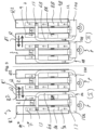
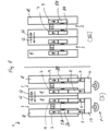
- FIGS. 3 and 4 illustrate a second storage facility 1, which is similar to the one described above and is therefore designated with like reference numerals and only substantial differences will be discussed below.
- this storage facility has two picking levels I and II arranged on top of each other. Their structure is similar to picking level I described above.
- a first lift 8a arranged in one of the pair of racking units R1 is fed by the storage-entry feeding line 4a and itself feeds the outbound line 6a of conveyor loop 11a in first picking level I, just as in facility 1 above, but circumnavigates around a second lift 8b arranged in the other of the pair of racking units R2, which is also of the drive-through-type and is fed by the storage-entry feeding line 4b and itself feeds the outbound line 6b of conveyor loop 11 b in a second picking level II, wherein the conveyor loop 11 b circumnavigates around the first lift 8a in the second picking level II.
- the lifts 8A, 8B are fed by an inbound-buffer 7 and feed into an outbound-buffer 9, as described above.
- the system basically includes two pick stations 10 located one on top of another in levels I and II and two drive-thru lifts 8A, 8B per aisle 2, wherein each lift 8a, b serves one level I, II of pick stations 10 only.
- buffer conveyors 7*, 9* Directly connected to the conveyor loop 11 (or conveyor 6) are two buffer conveyors 7*, 9*.
- One buffer conveyor 7* transports the units T for storage by shuttle 5, the other one 9* is installed on the opposite side for buffering units T that come from the storage merged into the conveyor loop 11 to be transported to the picking station 10.
- RATs 13 which are only used/installed if levels I and II are served by shuttles 5 and the buffer conveyors 7*, 9* for diverting units onto/from outbound conveyor 6.
- the special design of the conveyor loop 11 is that it is only connected to one lift 8 and one picking station 10.
- the conveyor 6a is routed around either in front or behind of the second lift 8b without any connection to it and connected to picking station 10a.
- the conveyor 6b circumnavigates the first lift 8a and connected to picking station 10b in the same but mirrored manner.
- the shuttles 5 have different working ranges within this system.
- the shuttles 5 on the two picking levels I, II only need to drive to the buffer conveyors 7*, 9* to serve the system with units T allocated to these levels.
- the shuttles 5 in the other non-picking (or storage only) levels III have full access to the complete aisle 2 because there is no conveyor loop linking to the picking stations 10. However there are two pair of buffer conveyors 7, 9 installed serving the lifts in one direction at each side of the aisle and the other direction on the other side of the aisle.
- the shuttle 5 passes the lifts 8 and can either drop units on the one side to the outbound buffer conveyor 9 to supply the lift with goods or on the other side it can pick up units T from the inbound buffer conveyor 7 coming from the lift.
- both picking stations 10 have full accessibility to every non-picking level III, but the levels I, II connecting the picking stations 10 only have the accessibility to either picking station 10a or 10b located at the same level unless unit T is routed through the pick station to get to another loop.
- the shuttle 5 picks it up and transports it to cross conveyance location Q, if the unit is not in the desired aisle 2, from where it is transferred to the adjoining aisle and picked up by shuttle 5.If necessary this process is repeated, until the unit reaches the destination aisle 2.
- the shuttle 5 picks up the unit T and transports it to the outbound buffer conveyor 9.
- the unit T If the unit T is brought to the buffer conveyor 9 at the picking station level I or II, it waits on the buffer until the time for this unit has come (i.e. the conveyor has a window/free space for the unit according to the required retrieval sequence of the order to be fulfilled) and is then merged into the outbound conveyor 6 of the loop 11 in the right sequence.
- the unit T is brought to the buffer conveyor 9 at another non-pinking level III, it will be picked by the lift 8 then dropped to the outbound conveyor 6 on the picking level I, II and then conveyed within the conveyor loop 11 to the picking stations 10 where it is processed.
- the unit T is returned back onto the inbound conveyor 4 on which this unit is then returned into the storage racking.
- the unit can be elevated to a storage level III or simply pass through the lift 8 if the storage destination is the picking level I, II.
- the unit is brought to the designated level III, it is dropped to the buffer conveyor 7 connected with the lift 8 serving the desired storage level III. Afterwards the shuttle 5 in the corresponding aisle 2 of the destination level picks up the storage unit T and stores it into the desired racking location.
- the units T on the outbound conveyor 6 on the way to the picking station 10 do not interfere with the other lift because the conveyor 6 or loop 11 is routed around this lift.
- the shuttles 5 and the buffer conveyors 7, 9 are optional as are also the cross conveyance locations Q.
- RATs 13 which are only used/installed if levels I and II are served by shuttles 5 and the buffer conveyors 7*, 9* for diverting units onto/from outbound conveyor 6.
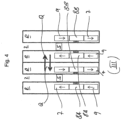
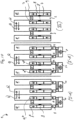
- Figure 5 is similar to the embodiment shown in figure 3 .
- Non-picking levels III are the same as in figure 4 , but second pair of buffer conveyors 7, 9 being optional in a rack R.
- the buffer conveyors are alternated in their conveying direction in every or every few levels, i.e. in even levels a rack R has buffer conveyors in a certain direction and in odd level in opposite direction if additional pair of buffer conveyors on each level are not allocated.
- Such an arrangement realizes the dual cycle lift operation which improves lift performance.
- Picking-level I has an inbound conveyors 4 which leads into both lift 8A and 8B, which are of the drive-through kind.
- the units T are intelligently distributed over two inbound conveyors 4 for optimum operation of lifts 8 and shuttles 5.
- Lift 8 in turn obviously may allow for a level change of units.
- To dispatch units from the racking to the picking station 10 etc. units are conveyed from lift 8A and 8B in level I onto outbound conveyor 6, where units T are intelligently merged from two lifts 8 for optimum operation of lifts 8, shuttles 5 and managing sequencing and for which the units are redirected via a RAT 13 onto outbound conveyor 6 and on to the picking station 10. Alternatively they may pass through RAT 13 onto buffer conveyor 7* in level I.
- Units to be dispatched from racking in level I are dropped off onto buffer conveyor 9* by shuttle 5 in level I, which is connected to outbound conveyor 6.
- Level I also has a second lift 8B in the same level together with conveyors 4, 6 so that the power of two lifting carriages can be utilized with a single picking station level. There may be more than one pick station per aisle and each are then located on top of each other.
- the buffer conveyors 7*, 9*, shuttles 5 and RAT's 13 as well as cross-conveyance locations Q are optional on this picking level.
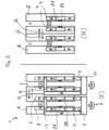
- the embodiment of figure 6 has a pair of inbound and outbound conveyors 4, 6 per aisle alternating by conveyor levels, so that each level I-A has two inbound conveyors 4 and each level I-B has two outbound conveyors 6.
- the two inbound conveyors 4 are directly on level I-A and the two outbound conveyors 6 are in a level I-B, which is not a full level below (or above), but beneath level I-A such that they both feed / dispatch from one picking level (same picking station 10).
- the picking station is connected to the lift via common connection conveyors 14 where units T are intelligently distributed over two inbound conveyors 4 for optimum operation of lifts 8 and shuttles 5 and the two outbound conveyors 6 are connected where units T are intelligently merged from two lifts for optimum operation of lifts, shuttles and managing sequencing and connected to the corresponding picking station 10 by a common connection conveyor 15.
- Non-picking levels III are the same as in figure 4 , with the second pair of buffer conveyors 7, 9 being optional in a rack R.
- the picking stations 10 are arranged on top (or below or even in the middle of) the storage racking R and on both sides of an aisle 2. More than one picking level can be used.
- each aisle 2 can be connected to two picking stations 10, one at each end (I-1), or alternatively each two aisles can be connected to two stations 10 at each end, consolidated by conveyors 16 (I-2).
- the picking level I is sourced by the lifts 8 and the stations 10 are connected by inbound conveyors 4 and outbound conveyors 6.
- the non-picking levels III are the same as above but always have a second of buffer conveyors 7, 9 for embodiment of level I-1 whilst those are still an option for embodiments of level I-2. They may have cross conveyance locations Q to both sides of the lifts 8.
- each aisle 2 of the picking level I has a pair of lifts 8, one in each rack R, one for inbound 8A and another one for outbound 8B transportation with inbound conveyor 4 feeding it and outbound conveyors 6 receiving from it respectively supplied from/to picking stations 10. More than one picking level may be installed.
- the other levels III correspond to level III as described above.
- Figure 9 three alternative layouts for connecting picking stations 10 to lifts 8 are shown.
- the non-picking levels III are the same as figure 5 .
- the picking levels IA, B are similar to figure 5 in that the outbound conveyor 6 circumvents one of the two lifts 8 of this level for sourcing of units to the picking station 10.
- the outbound conveyor is then split up and conveys units to the picking station 10A on two sides, as it is a dual person picking station. Finished order units may then be dispatched via shipping conveyor 20 directly from the picking station 10. Units that are to be returned to storage are dispatched correspondingly on two inbound conveyors 4, arranged flush to or below the outbound conveyor 6 that are merged and then divided again when entering the storage racking.
- the outbound conveyor 6 is arranged directly beneath/below (indicated by hashed lines) the inbound conveyors 4 and is split up to conveys units to the picking station 10B from below at two locations, typically one for order units O and one for donor units D but may act as dual person picking station that works similar way to level IA.
- Dispatch of the units is allowed by two inbound conveyors 4 that are merged and then divided again when entering the storage racking.
- the picking station 10C is also a two person operated picking station which is sourced by two outbound conveyors 6 directly connected to lifts and is dispatched by one inbound conveyor 4 between the racks of aisle 2connected to both lifts 8 via conveyor 16 where unit T is intelligently diverted into two lifts.
- the station 10C may have a shipping conveyor 20 connection for immediate dispatch of finished units.
- each rack R of an aisle 2 has a lift 8 and there are two conveyor levels as in figure 6 .
- this embodiment has one inbound conveyor 4 and one outbound conveyor 6 on each level I-A, I-B but with altered directions and both levels feed / dispatch dedicated picking stations 10 belonging to each level.
- the lifts 8 either stop at different levels (A or B) to serve the corresponding conveyors 4 or 6.
- Non-picking levels III are the same as in figure 4 , with the second pair of buffer conveyors 7, 9 being optional in a rack R and their direction alternating by each level or each few levels if such a second pair of buffer conveyors is not used.
Landscapes
- Engineering & Computer Science (AREA)
- Mechanical Engineering (AREA)
- Warehouses Or Storage Devices (AREA)
Claims (15)
- Verfahren zur Auftragserfüllung durch Bereitstellung von Auftrags- und/oder Produkteinheiten (T) aus einer Lagereinrichtung (1) in einer gewünschten Abfolge an einer Kommissionierstation (10), wobei die Lagereinrichtung umfasst:- ein Lagerregalsystem, umfassend eine Vielzahl von Mehrebenen-Lagerregalen (R), in denen Auftrags- und/oder Produkteinheiten gelagert werden, wobei die Lagerregale paarweise Rücken an Rücken angeordnet sind und zwischen Paaren einen Gang (2) aufweisen;- mindestens eine automatische Ein- und Auslagervorrichtung (5), wobei die Auftrags- und/oder Produkteinheiten durch die automatische Ein- und Auslagervorrichtung (5) eingelagert und von den Lagerregalen ausgelagert werden;- mindestens eine Hubvorrichtung (8), die verwendet wird, um die Auftrags- und/oder Produkteinheiten zu einem oder mehreren Lagerausgangsförderer(n) (6) zu übergeben;- mindestens einen Lagereingangsförderer (4) je Hubvorrichtung, der zum Zuführen von Auftrags- und/oder Produkteinheiten in das Lagerregalsystem vorgesehen ist;- mindestens einen Lagerausgangsförderer je Hubvorrichtung, der zum Auslagern von Auftrags- und/oder Produkteinheiten aus dem Lagerregalsystem vorgesehen ist;- mindestens eine voll- oder halbautomatische Kommissionierstation (10) zum Kommissionieren von Produkteinheiten zu Auftragseinheiten zum Erfüllen von Aufträgen, der Auftrags- und/oder Produkteinheiten zugeführt werden;- wobei jede Hubvorrichtung durch den Lagereingangsförderer und den Lagerausgangsförderer direkt mit einer Kommissionierstation in einer Kommissionierebene verbunden ist, dadurch gekennzeichnet, dass- die automatische Ein- und Auslagervorrichtung vom Shuttle-Typ ist, der je Gang und je Ebene für jeden Lagerregalsystemgang vorgesehen ist, und dadurch, dass- Auftrags- und/oder Produkteinheiten (T) direkt zwischen zwei angrenzenden Lagerregalen (R) von einem Ausgangslagerregal zu einem benachbarten Ziellagerregal über Querförderorte (Q) in den Lagerregalen selbst ausgetauscht werden und dass die mindestens eine Hubvorrichtung (8) in einem aus dem Paar von Regalen (R) eines Gangs angeordnet ist.
- Verfahren nach Anspruch 1, dadurch gekennzeichnet, dass eine Hubvorrichtung (8) in jedem Regal (R) eines Gangs angeordnet ist.
- Verfahren nach einem beliebigen der vorhergehenden Ansprüche, dadurch gekennzeichnet, dass das Shuttle (5) von der mindestens einen Hubvorrichtung (8) durch einen eingehenden Pufferförderer (7) und/oder einen abgehenden Pufferförderer (9) entkoppelt wird, wobei die Pufferförderer (7, 9) innerhalb der Regale (R) angeordnet sind.
- Verfahren nach einem beliebigen der vorhergehenden Ansprüche, dadurch gekennzeichnet, dass der Lagereingangsförderer (4) und der Lagerausgangsförderer (6) auf derselben Ebene angeordnet sind.
- Verfahren nach einem beliebigen der vorhergehenden Ansprüche 1 bis 3, dadurch gekennzeichnet, dass der Lagereingangsförderer (4) und der Lagerausgangsförderer (6) auf verschiedenen Ebenen angeordnet sind.
- Verfahren nach einem beliebigen der vorhergehenden Ansprüche, dadurch gekennzeichnet, dass die Querförderorte (Q) direkt hinter/neben dem eingehenden Pufferförderer (7) und/oder dem abgehenden Pufferförderer (9) innerhalb eines Regals (R) angeordnet sind.
- Verfahren nach einem beliebigen der vorhergehenden Ansprüche, dadurch gekennzeichnet, dass das Shuttle (5) selbst die Auftrags- und/oder Produkteinheiten (T) innerhalb der Querförderorte (Q) verlagert.
- Verfahren nach Anspruch 7, dadurch gekennzeichnet, dass das Shuttle (5) eines Ausgangsregals die Auftrags- und/oder Produkteinheiten (T) in den Querförderort (Q) in einem benachbarten Zielregal eingibt.
- Verfahren nach einem beliebigen der vorhergehenden Ansprüche, dadurch gekennzeichnet, dass ein Lagerregaleingang und -ausgang mit einer Fördererschleife (11) ausgebildet wird, die aus mindestens einem Lagereingangsförderer (4), mindestens einer Hubvorrichtung (8) und dem mindestens einen Lagerausgangsförderer (6) besteht, wobei die mindestens eine Hubvorrichtung (8) durch den Lagereingangsförderer (4) beliefert wird und ihrerseits den Lagerausgangsförderer (6) beliefert.
- Verfahren nach einem beliebigen der vorhergehenden Ansprüche 1 bis 9, dadurch gekennzeichnet, dass zwei oder mehr Hubvorrichtungen mit einer Kommissionierstation (10) verbunden sind.
- Verfahren nach einem beliebigen der vorhergehenden Ansprüche 1 bis 10, dadurch gekennzeichnet, dass nur eine Hubvorrichtung (8) mit einer oder mehreren Kommissionierstation(en) (10) verbunden ist.
- Verfahren nach einem beliebigen der vorhergehenden Ansprüche 1 bis 10, dadurch gekennzeichnet, dass zwei Hubvorrichtungen (8) in einem einzigen Gang (2) mit einer Station (10) auf einer einzigen Ebene verbunden sind.
- Verfahren nach einem beliebigen der vorhergehenden Ansprüche 1 bis 12, dadurch gekennzeichnet, dass die Lagereingangs- und/oder -ausgangsfördererebene optionale Pufferförderer aufweist, die Lagereingangs- und/oder -ausgangsförderer direkt beliefern oder von diesen beliefert werden.
- Verfahren nach einem beliebigen der vorhergehenden Ansprüche 1 bis 13, dadurch gekennzeichnet, dass Kommissionierstationen (10) einander gegenüberliegen und Hubvorrichtungen (8) zwischen diesen angeordnet sind.
- Verfahren nach einem beliebigen der vorhergehenden Ansprüche 1 bis 14, dadurch gekennzeichnet, dass zwei Kommissionierstationen (10) mit zwei Hubvorrichtungen (8) auf einer einzigen Ebene (I) verbunden sind, jedoch ohne Verwendung von Ein- und Ausschleusen.
Priority Applications (1)
| Application Number | Priority Date | Filing Date | Title |
|---|---|---|---|
| EP14734154.9A EP3022134B2 (de) | 2013-07-17 | 2014-07-01 | Verfahren zur auftragserfüllung durch bereitstellung von lagereinheiten in einer kommissionierstation |
Applications Claiming Priority (3)
| Application Number | Priority Date | Filing Date | Title |
|---|---|---|---|
| EP13176798.0A EP2826730A1 (de) | 2013-07-17 | 2013-07-17 | Verfahren zur Auftragserfüllung durch Bereitstellung von Lagereinheiten in einer Kommissionierstation |
| EP14734154.9A EP3022134B2 (de) | 2013-07-17 | 2014-07-01 | Verfahren zur auftragserfüllung durch bereitstellung von lagereinheiten in einer kommissionierstation |
| PCT/EP2014/063930 WO2015007514A1 (en) | 2013-07-17 | 2014-07-01 | Method of order fulfilling by preparing storage units at a picking station |
Publications (3)
| Publication Number | Publication Date |
|---|---|
| EP3022134A1 EP3022134A1 (de) | 2016-05-25 |
| EP3022134B1 EP3022134B1 (de) | 2017-03-22 |
| EP3022134B2 true EP3022134B2 (de) | 2024-04-17 |
Family
ID=48793953
Family Applications (2)
| Application Number | Title | Priority Date | Filing Date |
|---|---|---|---|
| EP13176798.0A Withdrawn EP2826730A1 (de) | 2013-07-17 | 2013-07-17 | Verfahren zur Auftragserfüllung durch Bereitstellung von Lagereinheiten in einer Kommissionierstation |
| EP14734154.9A Active EP3022134B2 (de) | 2013-07-17 | 2014-07-01 | Verfahren zur auftragserfüllung durch bereitstellung von lagereinheiten in einer kommissionierstation |
Family Applications Before (1)
| Application Number | Title | Priority Date | Filing Date |
|---|---|---|---|
| EP13176798.0A Withdrawn EP2826730A1 (de) | 2013-07-17 | 2013-07-17 | Verfahren zur Auftragserfüllung durch Bereitstellung von Lagereinheiten in einer Kommissionierstation |
Country Status (10)
| Country | Link |
|---|---|
| US (1) | US9988212B2 (de) |
| EP (2) | EP2826730A1 (de) |
| JP (1) | JP6321794B2 (de) |
| CN (1) | CN105392719B (de) |
| CA (1) | CA2917953C (de) |
| DK (1) | DK3022134T4 (de) |
| ES (1) | ES2625777T5 (de) |
| MX (1) | MX368500B (de) |
| SG (1) | SG11201606794SA (de) |
| WO (1) | WO2015007514A1 (de) |
Families Citing this family (60)
| Publication number | Priority date | Publication date | Assignee | Title |
|---|---|---|---|---|
| WO2016007940A1 (en) | 2014-07-11 | 2016-01-14 | Dematic Corp. | Picking station with automated warehouse |
| DE102014117235A1 (de) * | 2014-11-25 | 2016-05-25 | Dematic Gmbh | Verfahren zum Betreiben eines Fachbodenregallagers und entsprechendes Fachbodenregallager |
| JP6849604B2 (ja) | 2015-04-21 | 2021-03-24 | オペックス コーポレーション | 物品を保管または取り出す方法および装置 |
| US10336540B2 (en) | 2015-04-27 | 2019-07-02 | Attabotics Inc. | Storage and retrieval system |
| AT14694U1 (de) * | 2015-08-19 | 2016-04-15 | Knapp Ag | Kommissionierplatz zum Kommissionieren von Artikeln in Auftragsbehälter und Fördertaschen zur Auftrags- und Batchkommissionierung |
| JP6973994B2 (ja) * | 2015-10-30 | 2021-12-01 | トーヨーカネツ株式会社 | 立体自動倉庫 |
| JP6694126B2 (ja) * | 2015-11-11 | 2020-05-13 | トーヨーカネツ株式会社 | 立体自動倉庫 |
| EP3182348A1 (de) | 2015-12-17 | 2017-06-21 | Dematic Systems GmbH | Verfahren zur bestellerfüllung durch verfügbarmachung von lagereinheiten aus einer lagereinrichtung in gewünschter reihenfolge in einer aufnahmestation |
| CN105858043B (zh) * | 2016-05-27 | 2017-12-05 | 陕西科技大学 | 一种升降机与穿梭车结合的仓储系统优化调度方法 |
| NO344609B1 (en) * | 2016-06-06 | 2020-02-10 | Autostore Tech As | Conveyor with tilt function |
| WO2018006966A1 (en) * | 2016-07-07 | 2018-01-11 | Abb Schweiz Ag | A sequencing station |
| AT518818B1 (de) * | 2016-07-08 | 2018-06-15 | Tgw Logistics Group Gmbh | Verfahren zum Kommissionieren von Artikeln und Kommissionierstation |
| CN106219126B (zh) * | 2016-07-22 | 2018-07-10 | 鄢永军 | 一种全自动智能配送系统 |
| NO345223B1 (en) * | 2016-10-14 | 2020-11-09 | Autostore Tech As | Picking or supply station assembly for storage system and method of transferring an item to and/or from storage system |
| US20180137459A1 (en) * | 2016-11-16 | 2018-05-17 | Dematic Corp. | Waveless order fulfillment |
| CN106742307B (zh) * | 2016-12-21 | 2023-12-12 | 昆船智能技术股份有限公司 | 一种箱皮自动暂存和拣选供料系统和方法 |
| US10611568B2 (en) * | 2017-01-25 | 2020-04-07 | Intelligrated Headquarters, Llc | AS/RS lift having vertically-aligned dual carriages |
| MX2019010117A (es) * | 2017-02-24 | 2019-12-19 | Opex Corp | Sistemas y metodos automatizados de almacenamiento y recuperacion. |
| CN110325462B (zh) * | 2017-02-24 | 2020-12-08 | 欧佩克斯公司 | 自动存储和取回系统及用于操作该自动存储和取回系统的方法 |
| US10940998B2 (en) | 2017-02-24 | 2021-03-09 | Opex Corporation | Automated storage and retrieval system |
| DE102017104990A1 (de) | 2017-03-09 | 2018-09-13 | Dematic Gmbh | Verfahren zur Auslagerung von Waren aus einem Lager zur Auftragserfüllung |
| JP7167390B2 (ja) * | 2017-03-17 | 2022-11-09 | トーヨーカネツ株式会社 | 立体自動倉庫 |
| SG11201907933PA (en) * | 2017-04-20 | 2019-09-27 | Ihi Corp | Buffer device |
| CN107444824A (zh) * | 2017-09-30 | 2017-12-08 | 山东兰剑物流科技股份有限公司 | 集货缓存系统及料箱存储拣选系统 |
| CN107720066A (zh) * | 2017-09-30 | 2018-02-23 | 山东兰剑物流科技股份有限公司 | 蜂巢系统及料箱存储拣选系统 |
| CN107555056B (zh) * | 2017-09-30 | 2024-02-27 | 兰剑智能科技股份有限公司 | 料箱存储拣选系统和储分一体化系统 |
| WO2019120584A1 (en) | 2017-12-22 | 2019-06-27 | Dematic Gmbh | Method of order fulfilling by making storage units available from a storage facility in a desired sequence at a pack station |
| CN110147970B (zh) * | 2018-02-13 | 2024-06-18 | 北京京东尚科信息技术有限公司 | 一种仓储调度的方法和装置 |
| CN110406870B (zh) * | 2018-04-28 | 2021-05-25 | 菜鸟智能物流控股有限公司 | 一种仓库及仓库的储物对象、货架处理方法 |
| US20210097482A1 (en) * | 2018-04-30 | 2021-04-01 | Cargo Sous Terrain Ag | Transport, storage and sequencing system for goods |
| DE102018110502A1 (de) | 2018-05-02 | 2019-11-07 | Dematic Gmbh | Kommissioniereinrichtung zum Kommissionieren von einem Vorratsbehälter in einen Auftragsbehälter und entsprechendes Verfahren |
| JP7300468B2 (ja) | 2018-06-08 | 2023-06-29 | アタボティックス インコーポレイテッド | 保管格子と外部作業ステーションとの間で共通ロボット車両隊を共有する保管及び回収システム |
| US10913641B2 (en) | 2018-06-08 | 2021-02-09 | Attabotics Inc. | Storage units and robotic storage/retrieval vehicles for a three-dimensional storage system |
| CA3104332A1 (en) | 2018-06-21 | 2019-12-26 | Tgw Logistics Group Gmbh | Storage and order-picking system as well as order-picking method with improved transfer of goods between two storage zones |
| AT17767U1 (de) | 2018-06-21 | 2023-02-15 | Tgw Logistics Group Gmbh | Lager- und Kommissioniersystem sowie Kommissionierverfahren mit verbessertem Warentransfer zwischen zwei Lagerbereichen |
| EP3810530B1 (de) | 2018-06-21 | 2023-06-07 | TGW Logistics Group GmbH | Lager- und kommissioniersystem sowie verfahren zum kommissionieren von auftragswaren aus einer hängetasche und einem anderen ladehilfsmittel |
| US20200017298A1 (en) | 2018-07-12 | 2020-01-16 | Walmart Apollo, Llc | Autonomous storage and retrieval tower |
| GB2590246A (en) | 2018-07-12 | 2021-06-23 | Walmart Apollo Llc | System and method for product recognition and assignment at an automated storage and retrieval device |
| GB2590248A (en) | 2018-07-12 | 2021-06-23 | Walmart Apollo Llc | Automated storage retrieval system connection and communication protocol |
| GB2590267A (en) | 2018-07-12 | 2021-06-23 | Walmart Apollo Llc | Autonomous storage and retrieval tower |
| CN112424092B (zh) * | 2018-07-23 | 2022-08-02 | Tgw物流集团有限公司 | 具有缩短的通过时间的存放和拣选系统和用于运行其的方法 |
| US20200172337A1 (en) | 2018-10-31 | 2020-06-04 | Walmart Apollo, Llc | Systems and Methods for Object Storage and Retrieval |
| EP3887288B1 (de) * | 2018-11-28 | 2024-08-07 | Dematic Corp. | System und verfahren zur automatisierten lagerung bei mehreren temperaturen |
| AT521359B1 (de) | 2018-12-07 | 2020-01-15 | Tgw Mechanics Gmbh | Regallagersystem mit verbesserter Ladegut-Manipulationseinheit |
| CN109516051B (zh) * | 2018-12-25 | 2024-02-20 | 昆山新宁物流有限公司 | 一种自动化拣选系统 |
| CN111747008B (zh) * | 2019-03-28 | 2024-01-12 | 北京京东乾石科技有限公司 | 出库定位方法、装置和系统 |
| JP7566785B2 (ja) | 2019-06-11 | 2024-10-15 | アタボティックス インコーポレイテッド | 相互接続された保管構造と共通のロボットフリートを共有する製造セルを備える製造システム |
| US11352209B2 (en) * | 2019-06-28 | 2022-06-07 | Toyota Motor Engineering & Manufacturing North America, Inc. | Rear suspension member transfer assemblies and methods |
| WO2021009746A1 (en) * | 2019-07-14 | 2021-01-21 | Aquabot Ltd. | Order fulfillment system |
| WO2021009741A1 (en) * | 2019-07-14 | 2021-01-21 | Aquabot Ltd. | Order fulfillment system |
| CN112520283B (zh) * | 2019-09-19 | 2022-05-17 | 沛远智能科技(厦门)有限公司 | 自动运输、储存与取回系统及其方法 |
| JP7327145B2 (ja) * | 2019-12-19 | 2023-08-16 | 株式会社ダイフク | ピッキングシステム |
| EP4146568A1 (de) * | 2020-05-08 | 2023-03-15 | Dematic GmbH | Verfahren und station zum kommissionieren von artikeln nach dem waren-zu-mensch-prinzip |
| KR102873376B1 (ko) * | 2020-05-08 | 2025-10-17 | 데마틱 게엠베하 | 주문 이행을 위한 창고 |
| CN114056817A (zh) * | 2020-07-31 | 2022-02-18 | 江苏华章物流科技股份有限公司 | 存储拣选一体化设备及方法 |
| CN114056816A (zh) * | 2020-07-31 | 2022-02-18 | 江苏华章物流科技股份有限公司 | 存储拣选一体化设备及方法 |
| CN114313727B (zh) * | 2021-12-20 | 2024-09-27 | 珠海格力智能装备有限公司 | 生产工序间的智能仓库及其控制方法 |
| CN114476482B (zh) * | 2022-03-24 | 2022-12-20 | 深圳市海柔创新科技有限公司 | 料箱运送控制方法、装置、设备、系统、介质及产品 |
| EP4353630B1 (de) | 2022-10-13 | 2025-03-05 | Dematic GmbH | Lagersystem mit einem mehrebenen-lagergestell |
| CN116986249A (zh) * | 2023-08-10 | 2023-11-03 | 广汽埃安新能源汽车股份有限公司 | 一种汽车座椅卸货排序控制方法、装置、设备及存储介质 |
Family Cites Families (26)
| Publication number | Priority date | Publication date | Assignee | Title |
|---|---|---|---|---|
| JPS50138578A (de) * | 1974-04-26 | 1975-11-05 | ||
| JP3451031B2 (ja) * | 1999-03-18 | 2003-09-29 | 住友重機械工業株式会社 | 連接する自動倉庫間における横渡し機能付自動倉庫 |
| DE29912230U1 (de) | 1999-07-13 | 1999-11-11 | Witron Logistik + Informatik GmbH, 92711 Parkstein | Kommissionieranlage für Behälter |
| US6321138B1 (en) * | 2000-09-15 | 2001-11-20 | Woodson Incorporated | Storage and retrieval system with automated order make up |
| DE10136354B4 (de) * | 2001-07-26 | 2010-06-17 | Knapp Ag | Verfahren und Anlage zum Kommissionieren mit einem Behälterregal und zugeordnetem Regalbediengerät |
| DE20112328U1 (de) * | 2001-07-26 | 2002-01-31 | Knapp Logistik Automation Gmbh, Hart | Kommissionieranlage mit einem Behälterregal und zugeordnetem Regalbediengerät |
| DE10326553A1 (de) * | 2003-06-12 | 2005-01-05 | Siemens Ag | Kommissionierlagersystem zum Kommissionieren von Transporteinheiten |
| DE202004012021U1 (de) | 2004-07-27 | 2005-12-15 | Bellheimer Metallwerk Gmbh | Lagersystem |
| US7331471B1 (en) | 2004-12-28 | 2008-02-19 | Amazon Technologies, Inc. | System and method for modular sorting stations |
| DE102005045971A1 (de) * | 2005-09-26 | 2007-04-05 | Siemens Ag | Verfahren zur Kommissionierung und Kommissionieranlage |
| DE102006008932A1 (de) | 2006-02-22 | 2007-08-23 | Bellheimer Metallwerk Gmbh | Lagerliftanordnung |
| CN100537376C (zh) | 2006-03-27 | 2009-09-09 | 中邮物流有限责任公司 | 一种物流自动拣货盘点系统及其方法 |
| DE102006023477B4 (de) | 2006-05-18 | 2009-03-05 | Dematic Gmbh & Co. Kg | Lager- und Kommissioniersystem sowie Verfahren zum Kommissionieren |
| US8276739B2 (en) * | 2007-01-25 | 2012-10-02 | Bastian Material Handling, Llc | Three-dimensional automated pick module |
| DE102007010191A1 (de) | 2007-03-02 | 2008-09-04 | Dematic Gmbh & Co. Kg | Verfahren und System zum Bereitstellen von Transporteinheiten aus einem Lager in einer gewünschten vorgegebenen Reihenfolge auf mindestens einer Sammelstrecke |
| JP5278724B2 (ja) * | 2007-07-26 | 2013-09-04 | 株式会社ダイフク | 物品収納設備 |
| JP5432907B2 (ja) * | 2008-09-03 | 2014-03-05 | デマティック アカウンティング サービシーズ ゲーエムベーハー | 立体自動倉庫 |
| DE102009032406A1 (de) | 2009-07-09 | 2011-01-13 | Psb Intralogistics Gmbh | Regallagersystem und Verfahren zum Betreiben eines Regallagersystems |
| EP2544971B1 (de) * | 2010-03-12 | 2020-12-16 | Symbotic LLC | Nachschub- und auftragserfüllungssystem |
| US9280756B2 (en) | 2010-05-26 | 2016-03-08 | Amazon Technologies, Inc. | Managing individual item sequencing from a storage area to a packing station in a materials handling facility |
| FR2967145B1 (fr) * | 2010-11-08 | 2013-11-15 | Savoye | Systeme de stockage automatise comprenant au moins un elevateur dont au moins un mat porteur est forme par au moins un montant de la structure d'au moins une etagere |
| CN102101569B (zh) | 2011-01-26 | 2012-08-22 | 山东兰剑物流科技有限公司 | 一种集成化烟草物流仓库及其仓储、分拣包装方法 |
| DE102011106667A1 (de) | 2011-07-05 | 2013-01-10 | SSI Schäfer Noell GmbH Lager- und Systemtechnik | Lager- und Kommissioniersystem und Verfahren zum automatisierten Kommissionieren mit einem Kanallager |
| AT512339B1 (de) | 2011-12-21 | 2015-10-15 | Tgw Logistics Group Gmbh | Regallagersystem und verfahren zum betreiben desselben |
| CN102633077B (zh) | 2012-04-15 | 2014-06-25 | 昆明新高原电子信息有限公司 | 一种基于自动搬运小车的可搬运式货架仓储系统 |
| DE102012107176A1 (de) | 2012-08-06 | 2014-02-06 | Dematic Accounting Services Gmbh | Verfahren zum Bereitstellen von Transporteinheiten aus einem Lager |
-
2013
- 2013-07-17 EP EP13176798.0A patent/EP2826730A1/de not_active Withdrawn
-
2014
- 2014-07-01 JP JP2016526501A patent/JP6321794B2/ja active Active
- 2014-07-01 ES ES14734154T patent/ES2625777T5/es active Active
- 2014-07-01 MX MX2016000433A patent/MX368500B/es active IP Right Grant
- 2014-07-01 CA CA2917953A patent/CA2917953C/en active Active
- 2014-07-01 EP EP14734154.9A patent/EP3022134B2/de active Active
- 2014-07-01 CN CN201480040670.4A patent/CN105392719B/zh active Active
- 2014-07-01 SG SG11201606794SA patent/SG11201606794SA/en unknown
- 2014-07-01 WO PCT/EP2014/063930 patent/WO2015007514A1/en not_active Ceased
- 2014-07-01 DK DK14734154.9T patent/DK3022134T4/da active
-
2016
- 2016-01-15 US US14/996,965 patent/US9988212B2/en active Active
Also Published As
| Publication number | Publication date |
|---|---|
| DK3022134T3 (en) | 2017-07-03 |
| EP3022134A1 (de) | 2016-05-25 |
| SG11201606794SA (en) | 2016-09-29 |
| CA2917953A1 (en) | 2015-01-22 |
| ES2625777T3 (es) | 2017-07-20 |
| CN105392719B (zh) | 2017-09-22 |
| MX2016000433A (es) | 2016-06-28 |
| JP2016526520A (ja) | 2016-09-05 |
| JP6321794B2 (ja) | 2018-05-09 |
| CN105392719A (zh) | 2016-03-09 |
| EP2826730A1 (de) | 2015-01-21 |
| DK3022134T4 (da) | 2024-05-13 |
| US20160130086A1 (en) | 2016-05-12 |
| US9988212B2 (en) | 2018-06-05 |
| EP3022134B1 (de) | 2017-03-22 |
| MX368500B (es) | 2019-10-04 |
| WO2015007514A1 (en) | 2015-01-22 |
| CA2917953C (en) | 2020-08-04 |
| ES2625777T5 (es) | 2024-09-20 |
Similar Documents
| Publication | Publication Date | Title |
|---|---|---|
| EP3022134B2 (de) | Verfahren zur auftragserfüllung durch bereitstellung von lagereinheiten in einer kommissionierstation | |
| EP2826728B1 (de) | Verfahren zur Auftragserfüllung durch Bereitstellung von Lagereinheiten in einer Kommissionierstation | |
| EP2949604B1 (de) | Kommissionierungsverfahren mit mehreren auslagerliften in einer lageranlage | |
| EP3022135B1 (de) | Verfahren zur auftragserfüllung und auffüllung von lagereinheiten | |
| JP6679678B2 (ja) | 保管設備からの運搬ユニットを提供するための方法 | |
| US10934092B2 (en) | Method of order fulfilling by making storage units available from a storage facility in a desired sequence at a picking station | |
| EP2949605B1 (de) | Verfahren zur Befehlserfüllung durch Verfügbarmachung von Lagereinheiten aus einer Lagereinrichtung in einer Kommissionierungsstation |
Legal Events
| Date | Code | Title | Description |
|---|---|---|---|
| PUAI | Public reference made under article 153(3) epc to a published international application that has entered the european phase |
Free format text: ORIGINAL CODE: 0009012 |
|
| 17P | Request for examination filed |
Effective date: 20160211 |
|
| AK | Designated contracting states |
Kind code of ref document: A1 Designated state(s): AL AT BE BG CH CY CZ DE DK EE ES FI FR GB GR HR HU IE IS IT LI LT LU LV MC MK MT NL NO PL PT RO RS SE SI SK SM TR |
|
| AX | Request for extension of the european patent |
Extension state: BA ME |
|
| GRAP | Despatch of communication of intention to grant a patent |
Free format text: ORIGINAL CODE: EPIDOSNIGR1 |
|
| DAX | Request for extension of the european patent (deleted) | ||
| INTG | Intention to grant announced |
Effective date: 20161005 |
|
| GRAJ | Information related to disapproval of communication of intention to grant by the applicant or resumption of examination proceedings by the epo deleted |
Free format text: ORIGINAL CODE: EPIDOSDIGR1 |
|
| STAA | Information on the status of an ep patent application or granted ep patent |
Free format text: STATUS: REQUEST FOR EXAMINATION WAS MADE |
|
| GRAS | Grant fee paid |
Free format text: ORIGINAL CODE: EPIDOSNIGR3 |
|
| STAA | Information on the status of an ep patent application or granted ep patent |
Free format text: STATUS: GRANT OF PATENT IS INTENDED |
|
| GRAP | Despatch of communication of intention to grant a patent |
Free format text: ORIGINAL CODE: EPIDOSNIGR1 |
|
| INTC | Intention to grant announced (deleted) | ||
| GRAA | (expected) grant |
Free format text: ORIGINAL CODE: 0009210 |
|
| STAA | Information on the status of an ep patent application or granted ep patent |
Free format text: STATUS: THE PATENT HAS BEEN GRANTED |
|
| INTG | Intention to grant announced |
Effective date: 20170124 |
|
| RAP1 | Party data changed (applicant data changed or rights of an application transferred) |
Owner name: DEMATIC GMBH |
|
| AK | Designated contracting states |
Kind code of ref document: B1 Designated state(s): AL AT BE BG CH CY CZ DE DK EE ES FI FR GB GR HR HU IE IS IT LI LT LU LV MC MK MT NL NO PL PT RO RS SE SI SK SM TR |
|
| REG | Reference to a national code |
Ref country code: GB Ref legal event code: FG4D |
|
| REG | Reference to a national code |
Ref country code: CH Ref legal event code: EP |
|
| REG | Reference to a national code |
Ref country code: AT Ref legal event code: REF Ref document number: 877502 Country of ref document: AT Kind code of ref document: T Effective date: 20170415 |
|
| REG | Reference to a national code |
Ref country code: IE Ref legal event code: FG4D |
|
| REG | Reference to a national code |
Ref country code: CH Ref legal event code: NV Representative=s name: ALDO ROEMPLER PATENTANWALT, CH |
|
| REG | Reference to a national code |
Ref country code: DE Ref legal event code: R096 Ref document number: 602014007922 Country of ref document: DE |
|
| REG | Reference to a national code |
Ref country code: NL Ref legal event code: FP |
|
| REG | Reference to a national code |
Ref country code: DK Ref legal event code: T3 Effective date: 20170629 |
|
| REG | Reference to a national code |
Ref country code: ES Ref legal event code: FG2A Ref document number: 2625777 Country of ref document: ES Kind code of ref document: T3 Effective date: 20170720 |
|
| REG | Reference to a national code |
Ref country code: FR Ref legal event code: PLFP Year of fee payment: 4 |
|
| PG25 | Lapsed in a contracting state [announced via postgrant information from national office to epo] |
Ref country code: HR Free format text: LAPSE BECAUSE OF FAILURE TO SUBMIT A TRANSLATION OF THE DESCRIPTION OR TO PAY THE FEE WITHIN THE PRESCRIBED TIME-LIMIT Effective date: 20170322 Ref country code: LT Free format text: LAPSE BECAUSE OF FAILURE TO SUBMIT A TRANSLATION OF THE DESCRIPTION OR TO PAY THE FEE WITHIN THE PRESCRIBED TIME-LIMIT Effective date: 20170322 Ref country code: FI Free format text: LAPSE BECAUSE OF FAILURE TO SUBMIT A TRANSLATION OF THE DESCRIPTION OR TO PAY THE FEE WITHIN THE PRESCRIBED TIME-LIMIT Effective date: 20170322 Ref country code: GR Free format text: LAPSE BECAUSE OF FAILURE TO SUBMIT A TRANSLATION OF THE DESCRIPTION OR TO PAY THE FEE WITHIN THE PRESCRIBED TIME-LIMIT Effective date: 20170623 Ref country code: NO Free format text: LAPSE BECAUSE OF FAILURE TO SUBMIT A TRANSLATION OF THE DESCRIPTION OR TO PAY THE FEE WITHIN THE PRESCRIBED TIME-LIMIT Effective date: 20170622 |
|
| REG | Reference to a national code |
Ref country code: LT Ref legal event code: MG4D |
|
| PG25 | Lapsed in a contracting state [announced via postgrant information from national office to epo] |
Ref country code: RS Free format text: LAPSE BECAUSE OF FAILURE TO SUBMIT A TRANSLATION OF THE DESCRIPTION OR TO PAY THE FEE WITHIN THE PRESCRIBED TIME-LIMIT Effective date: 20170322 Ref country code: BG Free format text: LAPSE BECAUSE OF FAILURE TO SUBMIT A TRANSLATION OF THE DESCRIPTION OR TO PAY THE FEE WITHIN THE PRESCRIBED TIME-LIMIT Effective date: 20170622 Ref country code: LV Free format text: LAPSE BECAUSE OF FAILURE TO SUBMIT A TRANSLATION OF THE DESCRIPTION OR TO PAY THE FEE WITHIN THE PRESCRIBED TIME-LIMIT Effective date: 20170322 Ref country code: SE Free format text: LAPSE BECAUSE OF FAILURE TO SUBMIT A TRANSLATION OF THE DESCRIPTION OR TO PAY THE FEE WITHIN THE PRESCRIBED TIME-LIMIT Effective date: 20170322 |
|
| PG25 | Lapsed in a contracting state [announced via postgrant information from national office to epo] |
Ref country code: CZ Free format text: LAPSE BECAUSE OF FAILURE TO SUBMIT A TRANSLATION OF THE DESCRIPTION OR TO PAY THE FEE WITHIN THE PRESCRIBED TIME-LIMIT Effective date: 20170322 Ref country code: RO Free format text: LAPSE BECAUSE OF FAILURE TO SUBMIT A TRANSLATION OF THE DESCRIPTION OR TO PAY THE FEE WITHIN THE PRESCRIBED TIME-LIMIT Effective date: 20170322 Ref country code: EE Free format text: LAPSE BECAUSE OF FAILURE TO SUBMIT A TRANSLATION OF THE DESCRIPTION OR TO PAY THE FEE WITHIN THE PRESCRIBED TIME-LIMIT Effective date: 20170322 Ref country code: SK Free format text: LAPSE BECAUSE OF FAILURE TO SUBMIT A TRANSLATION OF THE DESCRIPTION OR TO PAY THE FEE WITHIN THE PRESCRIBED TIME-LIMIT Effective date: 20170322 |
|
| PG25 | Lapsed in a contracting state [announced via postgrant information from national office to epo] |
Ref country code: PL Free format text: LAPSE BECAUSE OF FAILURE TO SUBMIT A TRANSLATION OF THE DESCRIPTION OR TO PAY THE FEE WITHIN THE PRESCRIBED TIME-LIMIT Effective date: 20170322 Ref country code: SM Free format text: LAPSE BECAUSE OF FAILURE TO SUBMIT A TRANSLATION OF THE DESCRIPTION OR TO PAY THE FEE WITHIN THE PRESCRIBED TIME-LIMIT Effective date: 20170322 Ref country code: IS Free format text: LAPSE BECAUSE OF FAILURE TO SUBMIT A TRANSLATION OF THE DESCRIPTION OR TO PAY THE FEE WITHIN THE PRESCRIBED TIME-LIMIT Effective date: 20170722 Ref country code: PT Free format text: LAPSE BECAUSE OF FAILURE TO SUBMIT A TRANSLATION OF THE DESCRIPTION OR TO PAY THE FEE WITHIN THE PRESCRIBED TIME-LIMIT Effective date: 20170724 |
|
| REG | Reference to a national code |
Ref country code: DE Ref legal event code: R026 Ref document number: 602014007922 Country of ref document: DE |
|
| PLBI | Opposition filed |
Free format text: ORIGINAL CODE: 0009260 |
|
| PLAX | Notice of opposition and request to file observation + time limit sent |
Free format text: ORIGINAL CODE: EPIDOSNOBS2 |
|
| 26 | Opposition filed |
Opponent name: SSI SCHAEFER AUTOMATION GMBH Effective date: 20171218 |
|
| PG25 | Lapsed in a contracting state [announced via postgrant information from national office to epo] |
Ref country code: SI Free format text: LAPSE BECAUSE OF FAILURE TO SUBMIT A TRANSLATION OF THE DESCRIPTION OR TO PAY THE FEE WITHIN THE PRESCRIBED TIME-LIMIT Effective date: 20170322 |
|
| REG | Reference to a national code |
Ref country code: IE Ref legal event code: MM4A |
|
| PG25 | Lapsed in a contracting state [announced via postgrant information from national office to epo] |
Ref country code: IE Free format text: LAPSE BECAUSE OF NON-PAYMENT OF DUE FEES Effective date: 20170701 |
|
| PLBB | Reply of patent proprietor to notice(s) of opposition received |
Free format text: ORIGINAL CODE: EPIDOSNOBS3 |
|
| PG25 | Lapsed in a contracting state [announced via postgrant information from national office to epo] |
Ref country code: LU Free format text: LAPSE BECAUSE OF NON-PAYMENT OF DUE FEES Effective date: 20170701 |
|
| REG | Reference to a national code |
Ref country code: FR Ref legal event code: PLFP Year of fee payment: 5 |
|
| PG25 | Lapsed in a contracting state [announced via postgrant information from national office to epo] |
Ref country code: MT Free format text: LAPSE BECAUSE OF NON-PAYMENT OF DUE FEES Effective date: 20170701 |
|
| PG25 | Lapsed in a contracting state [announced via postgrant information from national office to epo] |
Ref country code: HU Free format text: LAPSE BECAUSE OF FAILURE TO SUBMIT A TRANSLATION OF THE DESCRIPTION OR TO PAY THE FEE WITHIN THE PRESCRIBED TIME-LIMIT; INVALID AB INITIO Effective date: 20140701 Ref country code: MC Free format text: LAPSE BECAUSE OF FAILURE TO SUBMIT A TRANSLATION OF THE DESCRIPTION OR TO PAY THE FEE WITHIN THE PRESCRIBED TIME-LIMIT Effective date: 20170322 |
|
| PG25 | Lapsed in a contracting state [announced via postgrant information from national office to epo] |
Ref country code: CY Free format text: LAPSE BECAUSE OF FAILURE TO SUBMIT A TRANSLATION OF THE DESCRIPTION OR TO PAY THE FEE WITHIN THE PRESCRIBED TIME-LIMIT Effective date: 20170322 |
|
| PG25 | Lapsed in a contracting state [announced via postgrant information from national office to epo] |
Ref country code: MK Free format text: LAPSE BECAUSE OF FAILURE TO SUBMIT A TRANSLATION OF THE DESCRIPTION OR TO PAY THE FEE WITHIN THE PRESCRIBED TIME-LIMIT Effective date: 20170322 |
|
| APAH | Appeal reference modified |
Free format text: ORIGINAL CODE: EPIDOSCREFNO |
|
| APBM | Appeal reference recorded |
Free format text: ORIGINAL CODE: EPIDOSNREFNO |
|
| APBP | Date of receipt of notice of appeal recorded |
Free format text: ORIGINAL CODE: EPIDOSNNOA2O |
|
| PG25 | Lapsed in a contracting state [announced via postgrant information from national office to epo] |
Ref country code: TR Free format text: LAPSE BECAUSE OF FAILURE TO SUBMIT A TRANSLATION OF THE DESCRIPTION OR TO PAY THE FEE WITHIN THE PRESCRIBED TIME-LIMIT Effective date: 20170322 |
|
| APBQ | Date of receipt of statement of grounds of appeal recorded |
Free format text: ORIGINAL CODE: EPIDOSNNOA3O |
|
| PG25 | Lapsed in a contracting state [announced via postgrant information from national office to epo] |
Ref country code: AL Free format text: LAPSE BECAUSE OF FAILURE TO SUBMIT A TRANSLATION OF THE DESCRIPTION OR TO PAY THE FEE WITHIN THE PRESCRIBED TIME-LIMIT Effective date: 20170322 |
|
| REG | Reference to a national code |
Ref country code: AT Ref legal event code: UEP Ref document number: 877502 Country of ref document: AT Kind code of ref document: T Effective date: 20170322 |
|
| APBY | Invitation to file observations in appeal sent |
Free format text: ORIGINAL CODE: EPIDOSNOBA2O |
|
| APAH | Appeal reference modified |
Free format text: ORIGINAL CODE: EPIDOSCREFNO |
|
| APBU | Appeal procedure closed |
Free format text: ORIGINAL CODE: EPIDOSNNOA9O |
|
| PUAH | Patent maintained in amended form |
Free format text: ORIGINAL CODE: 0009272 |
|
| STAA | Information on the status of an ep patent application or granted ep patent |
Free format text: STATUS: PATENT MAINTAINED AS AMENDED |
|
| 27A | Patent maintained in amended form |
Effective date: 20240417 |
|
| AK | Designated contracting states |
Kind code of ref document: B2 Designated state(s): AL AT BE BG CH CY CZ DE DK EE ES FI FR GB GR HR HU IE IS IT LI LT LU LV MC MK MT NL NO PL PT RO RS SE SI SK SM TR |
|
| REG | Reference to a national code |
Ref country code: DE Ref legal event code: R102 Ref document number: 602014007922 Country of ref document: DE |
|
| REG | Reference to a national code |
Ref country code: DK Ref legal event code: T4 Effective date: 20240507 |
|
| REG | Reference to a national code |
Ref country code: NL Ref legal event code: FP |
|
| REG | Reference to a national code |
Ref country code: ES Ref legal event code: DC2A Ref document number: 2625777 Country of ref document: ES Kind code of ref document: T5 Effective date: 20240920 |
|
| PGFP | Annual fee paid to national office [announced via postgrant information from national office to epo] |
Ref country code: NL Payment date: 20250721 Year of fee payment: 12 |
|
| PGFP | Annual fee paid to national office [announced via postgrant information from national office to epo] |
Ref country code: ES Payment date: 20250826 Year of fee payment: 12 |
|
| PGFP | Annual fee paid to national office [announced via postgrant information from national office to epo] |
Ref country code: DK Payment date: 20250725 Year of fee payment: 12 Ref country code: DE Payment date: 20250722 Year of fee payment: 12 |
|
| PGFP | Annual fee paid to national office [announced via postgrant information from national office to epo] |
Ref country code: IT Payment date: 20250724 Year of fee payment: 12 |
|
| PGFP | Annual fee paid to national office [announced via postgrant information from national office to epo] |
Ref country code: BE Payment date: 20250721 Year of fee payment: 12 Ref country code: GB Payment date: 20250722 Year of fee payment: 12 |
|
| PGFP | Annual fee paid to national office [announced via postgrant information from national office to epo] |
Ref country code: FR Payment date: 20250725 Year of fee payment: 12 Ref country code: AT Payment date: 20250722 Year of fee payment: 12 |
|
| PGFP | Annual fee paid to national office [announced via postgrant information from national office to epo] |
Ref country code: CH Payment date: 20250801 Year of fee payment: 12 |