EP3021048A1 - Wärmeerzeugungssystem - Google Patents
Wärmeerzeugungssystem Download PDFInfo
- Publication number
- EP3021048A1 EP3021048A1 EP15003200.1A EP15003200A EP3021048A1 EP 3021048 A1 EP3021048 A1 EP 3021048A1 EP 15003200 A EP15003200 A EP 15003200A EP 3021048 A1 EP3021048 A1 EP 3021048A1
- Authority
- EP
- European Patent Office
- Prior art keywords
- heating
- tube
- heat
- heating system
- pipe
- Prior art date
- Legal status (The legal status is an assumption and is not a legal conclusion. Google has not performed a legal analysis and makes no representation as to the accuracy of the status listed.)
- Granted
Links
Images
Classifications
-
- F—MECHANICAL ENGINEERING; LIGHTING; HEATING; WEAPONS; BLASTING
- F24—HEATING; RANGES; VENTILATING
- F24D—DOMESTIC- OR SPACE-HEATING SYSTEMS, e.g. CENTRAL HEATING SYSTEMS; DOMESTIC HOT-WATER SUPPLY SYSTEMS; ELEMENTS OR COMPONENTS THEREFOR
- F24D3/00—Hot-water central heating systems
- F24D3/12—Tube and panel arrangements for ceiling, wall, or underfloor heating
-
- F—MECHANICAL ENGINEERING; LIGHTING; HEATING; WEAPONS; BLASTING
- F24—HEATING; RANGES; VENTILATING
- F24D—DOMESTIC- OR SPACE-HEATING SYSTEMS, e.g. CENTRAL HEATING SYSTEMS; DOMESTIC HOT-WATER SUPPLY SYSTEMS; ELEMENTS OR COMPONENTS THEREFOR
- F24D13/00—Electric heating systems
- F24D13/02—Electric heating systems solely using resistance heating, e.g. underfloor heating
-
- E—FIXED CONSTRUCTIONS
- E04—BUILDING
- E04B—GENERAL BUILDING CONSTRUCTIONS; WALLS, e.g. PARTITIONS; ROOFS; FLOORS; CEILINGS; INSULATION OR OTHER PROTECTION OF BUILDINGS
- E04B1/00—Constructions in general; Structures which are not restricted either to walls, e.g. partitions, or floors or ceilings or roofs
- E04B1/62—Insulation or other protection; Elements or use of specified material therefor
- E04B1/70—Drying or keeping dry, e.g. by air vents
- E04B1/7007—Drying or keeping dry, e.g. by air vents by using electricity, e.g. electro-osmosis
-
- Y—GENERAL TAGGING OF NEW TECHNOLOGICAL DEVELOPMENTS; GENERAL TAGGING OF CROSS-SECTIONAL TECHNOLOGIES SPANNING OVER SEVERAL SECTIONS OF THE IPC; TECHNICAL SUBJECTS COVERED BY FORMER USPC CROSS-REFERENCE ART COLLECTIONS [XRACs] AND DIGESTS
- Y02—TECHNOLOGIES OR APPLICATIONS FOR MITIGATION OR ADAPTATION AGAINST CLIMATE CHANGE
- Y02B—CLIMATE CHANGE MITIGATION TECHNOLOGIES RELATED TO BUILDINGS, e.g. HOUSING, HOUSE APPLIANCES OR RELATED END-USER APPLICATIONS
- Y02B30/00—Energy efficient heating, ventilation or air conditioning [HVAC]
Definitions
- the invention relates to a heat generation system, in particular a heating and drying system.
- the invention relates to a heating system having a single preferably straight tube having a heating wire in the form of an ohmic heating and a heat-conducting liquid.
- a tube in which the ohmic heating and a heat-conducting liquid is contained wherein the tube is preferably a copper tube with a diameter of preferably 10 mm to 30 mm, that is preferably 10 mm, 11 mm, 12 mm, 13 mm, 14 mm, 15 mm, 16 mm, 17 mm, 18 mm, 19 mm, 20 mm, 21 mm, 22 mm , 23 mm, 24 mm, 25 mm, 26 mm, 27 mm, 28 mm, 29 mm, 30 mm, preferably 15 mm to 25 mm, particularly preferably 20 to 25 mm, very particularly preferably a commercially available 22 mm tube is.
- the tube may have a length of preferably 1 m to 20 m, that is to say preferably 1 m, 2 m, 3 m, 4 m, 5 m, 6 m, 7 m, 8 m, 9 m, 10 m, 11 m, 12 m , 13 m, 14 m, 15 m, 16 m, 17 m, 18 m, 19 m, 20 m, preferably 1 m to 10 m, particularly preferably 1 m to 5 m.
- the tube is preferably a self-contained system of a single tube, which may have different lengths as described above.
- the tube is preferably a straight tube, which may also have bends.
- This first tube is preferably used as a heater when it is exposed bare. If the first tube is inside the masonry, but preferably is not plastered, it will serve as wall drying as it breaks the capillary-carrying layer in the wall. In this form, the pipe is used only for drying and can also be used in countries where no heating is needed, for example in countries where there is normally no heating, such as in the tropics. (Southern European countries).
- this first tube also preferably has extensions, wherein the extensions in the form of sleeves, tubes, which are preferably hollow, which are in thermal connection to the first tube and in the masonry, similar to a dowel, protrude.
- These extensions are preferably made of the same material as the tube, which is made of a thermally conductive metal such as preferably aluminum, steel, copper, preferably copper. These extensions are preferably every 20 cm to 45 cm, so preferably 20 cm, 21 cm, 22 cm, 23 cm, 24 cm, 25 cm, 26 cm, 27 cm, 28 cm, 29 cm, 30 cm, 31 cm, 32 cm, 33 cm, 34 cm, 35 cm, 36 cm, 37 cm, 38 cm, 39 cm, 40 cm, 41 cm, 42 cm, 43 cm, 44 cm, 45 cm preferably present and preferably 1 cm to 10 cm, thus preferably 1 cm, 2 cm, 3 cm, 4 cm, 5 cm, 6 cm, 7 cm, 8 cm, 9 cm, 10 cm long, preferably 3, 4, 5, 6 cm long and have a diameter of preferably 3 mm to 15 mm, that is preferably 3 mm, 4 mm, 5 mm, 6 mm, 7 mm, 8 mm, 9 mm, 10 mm, 11 mm , 12 mm, 13 mm, 14 mm,
- the first tube no longer must be within the masonry, since the extensions of the invention are easier wall drying, since now only the extensions must be within the masonry, what a simple hole in the masonry is sufficient to break the capillary layer in the wall.
- the tube with the heat-conducting extensions according to the invention is preferably used for drying.
- another second preferably straight tube can be connected in parallel via at least two connecting tubes (per running meter), which also has a heating wire in the form of an ohmic Heating and having a heat-conducting liquid.
- These two tubes form a heat generating system, such as preferably a heating, drying system.
- This heating system with two parallel tubes, preferably via T-pieces, which are at a preferably 90 ° angle to the respective pipe that connects them, can also be used as window element heating, so be mounted below a glass pane, eg on the windowsill below a windowpane is located.
- the T-piece may also be absent in that a hole is preferably completely through the first tube (preferably if the two tubes are already connected to one another, preferably soldered), whereby this bore only continues through a wall in the second tube, so that the two pipes in fluid communication, gas connection, all holes are soldered to the outside liquid-tight and gas-tight, so that no liquid, gas, steam through the holes can penetrate to the outside, ie that in each case a bore of each tube touches hole on hole and so the two pipes are in communication through the holes and liquid, gas, steam can pass from one pipe to the other.
- a bore extends in each case one of the tubes, which can be brought to coincide, so as to establish a connection, fluid connection, gas connection, between the two tubes, wherein the two holes, which are brought into coverage, sealed at their edges to the outside be sealed, preferably by solder, the holes must not be soldered in any case.
- the two tubes are already preferably previously connected to each other, preferably soldered, must be drilled through the entire first tube.
- a second tube to the first tube with a diameter of preferably 10 mm to 30 mm, that is preferably 10 mm, 11 mm, 12 mm, 13 mm, 14 mm , 15 mm, 16 mm, 17 mm, 18 mm, 19 mm, 20 mm, 20 mm, 21 mm, 22 mm, 23 mm, 24 mm, 25 mm, 26 mm, 27 mm, 28 mm, 29 mm, 30 mm, preferably 15 mm to 25 mm, particularly preferably 20 to 25 mm, especially 15 mm in diameter copper pipe completely with the first preferably 18 mm, 19 mm, 20 mm, 21 mm, 22 mm thick pipe connected.
- the heating power is selected depending on the volume of the tubes. Both heating cables are installed in a watertight manner and also installed directly at the insertion opening to 220 volts watertight. Preferably, there is also a device for pressure equalization on at least one pipe, such as preferably an open riser or preferably a pressure equalization tank or preferably the pipe or pipe system is not completely filled with the heat-conducting liquid.
- the pressure equalization takes place in two tubes preferably on the upper tube. In a riser (flush-mounted or surface-mounted), the main current-carrying cables (eg three-pole cable 3 x 1.5 mm) are connected to the control at operating height.
- a preferred embodiment of the invention is a heat generation system, heating system, which consists of a lower tube, preferably of copper, preferably painted with clearcoat, and ohmic heating (power consumption preferably 30 watts) and an upper tube preferably made of copper, preferably painted with clearcoat, and preferably an ohmic heater (power consumption preferably 10 watts), wherein the diameter of the upper tube is preferably a smaller diameter than the diameter of the lower tube.
- the two tubes, the upper tube, the lower tube or both tubes, preferably the contact gap of the two tubes preferably has extensions, which may also be attached to one or both tubes, wherein the extensions in the form of sleeves, tubes, preferably are hollow, which are in thermal connection to the first pipe and in the masonry, similar to a dowel, protrude.
- These extensions are preferably made of the same material as the tube, which is made of a thermally conductive metal such as preferably aluminum, steel, copper, preferably copper.
- These extensions are preferably every 20 cm to 45 cm, so preferably 20 cm, 21 cm, 22 cm, 23 cm, 24 cm, 25 cm, 26 cm, 27 cm, 28 cm, 29 cm, 30 cm, 31 cm, 32 cm, 33 cm, 34 cm, 35 cm, 36 cm, 37 cm, 38 cm, 39 cm, 40 cm, 41 cm, 42 cm, 43 cm, 44 cm, 45 cm, preferably present and preferably 1 cm to 10 cm
- preferably 1 cm, 2 cm, 3 cm cm, 4 cm, 5 cm, 6 cm, 7 cm, 8 cm, 9 cm, 10 cm long preferably 3 cm, 4 cm, 5 cm, 6 cm long and have a diameter of preferably 3 mm to 15 mm, that is preferably 3 mm, 4 mm, 5 mm, 6 mm, 7 mm, 8 mm, 9 mm, 10 mm, 11 mm, 12 mm, 13 mm, 14 mm, 15 mm , preferably 8 mm.
- These extensions are thermally conductive.
- Both tubes are preferably verkoffered with cover plates, which have a gap both above and below, so that a chimney effect occurs when heating the tubes, so convection occurs.
- the sheets are preferably made of metal such as aluminum, steel, copper, with copper being preferred.
- the thermally conductive liquid preferably contains at least 0.1% by weight of carbon to 7.5% by weight, preferably 0.1% by weight, 0.2% by weight, 0.3% by weight, 0.4% by weight, 0.5 wt.%, 0.6 wt.%, 0.7 wt.%, 0.8 wt.%, 0.9 wt.%, 1 wt.%, 1.5 wt.%, 2 wt. %, 2.5% by weight, 3% by weight, 3.5% by weight, 4% by weight, 4.5% by weight, 5% by weight, 5.5% by weight, 6% by weight, 6.5% by weight, 7% by weight, 7.5% by weight, etc.
- the basis of the heat-conducting liquid is preferably tap water.
- the carbon source it is preferable to use coal, charcoal, lignite, hard coal, carbon black and graphite, which are finely ground and suspended in tap water.
- a combination of graphite and the other carbon sources such as preferably charcoal, lignite, hard coal, with charcoal being preferred.
- copper salts such as copper sulfate, magnesium salts, such as magnesium oxide, calcium salts, such as calcium carbonate, aluminum, such as aluminum oxide, zinc, such as zinc oxide, titanium, such as titanium oxide alone or in any mixtures with the other carbon sources and / or graphite in amounts of preferably 0 , 01 wt%, 0.02 wt%, 0.03 wt%, 0.04 wt%, 0.05 wt%, 0.06 wt%, 0.07 wt%, 0, 08 wt.%, 0.09 wt.%, 0.1 wt.%, 0.2 wt.%, 0.3 wt.%, 0.4 wt.%, 0.5 wt.%, 0.6 % By weight, 0.7% by weight, 0.8% by weight, 0.9% by weight, 1% by weight, etc. may be combined.
- biocides such as antimicrobial substances are added to the heat-conducting liquid, such as colloidal silver, preferably 1 mg / l to 200 mg / l, preferably 1 mg / l, 2 mg / l, 3 mg / l, 4 mg / l, 5 mg / l, 6 mg / l, 7 mg / l, 8 mg / l, 9 mg / l, 10 mg / l, 11 mg / l, 12 mg / l, 13 mg / l, 14 mg / l, 15 mg / l, 16 mg / l, 17 mg / l, 18 mg / l, 19 mg / l, 20 mg / l, 25 mg / l, 30 mg / l, 35 mg / l, 40 mg / l, 45 mg / l, 50 mg / l, 55 mg / l, 60 mg / l, 65 mg / l, 70 mg /
- Colloidal silver is preferably prepared from elemental silver or sparingly soluble in water silver salts and has a dimension of preferably 1 nm to 100 nm.
- silica gel may also be added, preferably 0.01% by weight, 0.02% by weight, 0.03% by weight, 0.04% by weight, 0.05% by weight, 0.06% by weight, 0.07 wt%, 0.08 wt%, 0.09 wt%, 0.1 wt%, 0.2 wt%, 0.3 wt%, 0.4 wt%, 0 , 5 wt.%, 0.6 wt.%, 0.7 wt.%, 0.8 wt.%, 0.9 wt.%, 1 wt.% 1.1 wt.%, Etc. in 0.1 Steps up to 3% by weight of silica gel.
- a claw mat is preferably present, which is preferably plastered.
- the cladding mat which is preferably plastered, is preferably at a height of preferably 30 cm, 31 cm, 32 cm, 33 cm, 34 cm, 35 cm, 36 cm, 37 cm, 38 cm, 39 cm, 40 cm, 41 cm , 42 cm, 43 cm, 44 cm, 45 cm, 46 cm, 47 cm, 48 cm, 49 cm, 50 cm, 51 cm, 52 cm, 53 cm, 54 cm, 55 cm above the floor.
- This cladding mat causes: 1.) By force decoupling of the visible plaster from the masonry - no or extremely strong restriction of Schadsalwa within masonry in the external plaster. 2.) A heat-storing air gap (pure radiant heat).
- the plaster is preferably in a thickness of about 0.3 to 2 cm, so preferably 0.3 cm, 0.4 cm, 0.5 cm, 0.6 cm, 0.7 cm, 0.8 cm, 0 , 9 cm, 1 cm, 1.1 cm, 1.2 cm, 1.3 cm, 1.4 cm, 1.5 cm, 1.6 cm, 1.7 cm, 1.8 cm, 1.9 cm, 2 cm, preferably 1 cm applied, wherein the special plaster is preferably mixed with graphite dust in order to effect a better heat storage.
- a highly diffusion-open wall paint is preferably used, which is preferably 5% by weight, 6% by weight, 7% by weight, 8% by weight, 9% by weight, 10% by weight, 11 wt%, 12 wt%, 13 wt%, 14 wt%, 15 wt% talc.
- biocides such as antimicrobials are added to the wall paint, such as colloidal silver, preferably 1 to 200 mg / l, preferably 1 mg / l, 2 mg / l, 3 mg / l, 4 mg / l, 5 mg / l , 6 mg / l, 7 mg / l, 8 mg / l, 9 mg / l, 10 mg / l, 11 mg / l, 12 mg / l, 13 mg / l, 14 mg / l, 15 mg / l, 16 mg / l, 17 mg / l, 18 mg / l, 19 mg / l, 20 mg / l, 25 mg / l, 30 mg / l, 35 mg / l, 40 mg / l, 45 mg / l, 50 mg / l, 55 mg / l, 60 mg / l, 65 mg / l, 70 mg / l, 75 mg / / /
- the front insertion openings were sealed by means of preferably shrink tubing or preferably fitted, sealed supply connections.
- At the rear end of e.g. preferably 18 mm, 19 mm, 20 mm, 21 mm, 22 mm thick tube is used as pressure equalization e.g. preferably 15 mm copper pipe vertically preferably about 4 cm above the insertion opening attached (possibly flush).
- pressure equalization e.g. preferably 18 mm, 19 mm, 20 mm, 21 mm, 22 mm thick copper tube attached shrink tubing.
- the rear wall pipe should not be plastered (deliberate or intentional heat accumulation). Furthermore, this heat accumulation serves as intended and serves to interrupt the capillary-carrying layer. To be favoured
- Basic structure In 230 ml of tap water in a tube of 87 cm length and 7 cm diameter with an ohmic heating at a constant 30 watts is at an initial temperature of 19 ° C the Heat the heat transfer medium for 2 hours.
- the substances are mentioned in terms of quantity, which are suspended or dissolved in the tap water and the temperature which is reached after 2 hours.
- the temperature and watt measurements were made using commercially available devices of the lower price category.
- a tube temperature of about 42 degrees can be achieved with a cumulative wattage of preferably about 20 watts (measurements at about 14 degrees room temperature).
- the power consumption of preferably about 20 watts will be significantly reduced.
- a higher cotton wool setting on the front pipe would, in reverse, result in wall dehumidification, so to speak, at no additional cost.
- the wall duct (rear) should be operated with approx. 7 watts. This resulted in a tube temperature of about 28 degrees.
- liquid medium When using normal tap water (as with conventional heating): When testing on 3 equal 15 mm tubes with tap water: about 43.6 degrees with carbon dioxide water: about 50.0 degrees with carbon water, colloidal silver, silica gel: about 52.2 degrees
- the 30 Watt constant heating cable was set on the dimmer to 10 watts of power.
- the 23 watts self-regulating heating cable was set to 8 watts.
- Nominal value 15 watts / running meter.
- Switch-on time 24 hours
- Current price: 20 cents / kwh heating price? 26, 62 euros per year / running meter
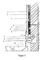
- FIG. 1 A first figure.
- FIG. 1 shows the heating and drying system according to the invention.
- a Krallgewebe 2 is fixed with a knock anchor 4, the glass or plastered with plaster 3, wherein between plaster 3 and 2 Krallgewebe can still be an additional tissue 5.
- This plaster has a color 6.
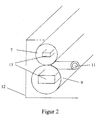
- FIG. 2 shows the heat generating system according to the invention, which has a smaller diameter upper tube 7 and a lower diameter tube 9. Between the tubes, one of the heat-conducting extensions 11 according to the invention can be seen. To the tubes, the Verkofftation 12 can be seen and in the tubes 7 and 9, the connections 13th
Landscapes
- Engineering & Computer Science (AREA)
- Physics & Mathematics (AREA)
- Thermal Sciences (AREA)
- Chemical & Material Sciences (AREA)
- Combustion & Propulsion (AREA)
- Mechanical Engineering (AREA)
- General Engineering & Computer Science (AREA)
- Central Heating Systems (AREA)
- Paints Or Removers (AREA)
Abstract
Description
- Die Erfindung betrifft ein Wärmeerzeugungssystem, insbesondere ein Heiz- und Trocknungssystem.
- Bekannt sind Systeme wie zum Beispiel von Großeschmidt. Diese Systeme werden als Hüllflächentemperierungen - Bauteiltemperierung bezeichnet, sie werden an das bestehende Heizungssystem angeschlossen (Öl-, Gas-, Holz- Wärmepumpe). Außerdem gibt es zum Beispiel Anwendungen (wie Konrad Fischer), wo beispielsweise Heizkabel an betroffene feuchte Bauteile offen oder eingeputzt an der Wand, der Außenwand verlegt werden.
- Aufgabe der Erfindung ist es, den Stand der Technik zu verbessern und insbesondere ein Wärmeerzeugungssystem, wie ein Heiz- und Trocknungssystem zur Verfügung zu stellen, das einfach in jedem Gebäude zu installieren ist und wenig Energie verbraucht.
- Gegenstand der Erfindung ist ein Heizsystem, das ein einziges vorzugsweise gerades Rohr aufweist, das einen Heizdraht in Form einer ohmschen Heizung und eine wärmeleitende Flüssigkeit aufweist.
- Zum Beispiel in einem Einfamilienhaus oder Wohnung mit einer Deckenhöhe von 2,50 m bis 3 m verläuft, vorzugsweise ab 2 cm über Oberkante Fußboden, ein Rohr, in dem die ohmsche Heizung und eine wärmeleitende Flüssigkeit enthalten ist, wobei das Rohr vorzugsweise ein Kupferrohr mit einem Durchmesser von vorzugsweise 10 mm bis 30 mm, also vorzugsweise 10 mm, 11 mm, 12 mm, 13 mm, 14 mm, 15 mm, 16 mm, 17 mm, 18 mm, 19 mm, 20 mm, 21 mm, 22 mm, 23 mm, 24 mm, 25 mm, 26 mm, 27 mm, 28 mm, 29 mm, 30 mm, bevorzugt 15 mm bis 25 mm, besonders bevorzugt 20 bis 25 mm, ganz besonders bevorzugt ein handelsübliches 22 mm Rohr ist. Das Rohr kann eine Länge von vorzugsweise 1 m bis 20 m, also vorzugsweise 1 m, 2 m, 3 m, 4 m, 5 m , 6 m, 7 m, 8 m, 9 m, 10 m, 11 m, 12 m, 13 m, 14 m, 15 m, 16 m, 17 m, 18 m, 19 m, 20 m, bevorzugt 1 m bis 10 m, besonders bevorzugt 1 m bis 5 m aufweisen.
- Dieses System kann auch unterhalb eines Fensters oder eines Glaselements verlaufen. Das Rohr ist vorzugsweise ein in sich geschlossenes System aus einem einzigen Rohr, das wie oben beschrieben unterschiedliche Länge aufweisen kann. Das Rohr ist vorzugsweise ein gerades Rohr, das auch Krümmungen aufweisen kann.
- Dieses erste Rohr dient vorzugsweise als Heizung, wenn es unverputzt frei liegt. Wenn das erste Rohr sich innerhalb des Mauerwerks befindet, aber vorzugsweise nicht verputzt ist, dient es der Mauertrocknung, da es die kapillarführende Schicht in der Mauer unterbricht. In dieser Form wird das Rohr nur zur Trocknung verwendet und kann auch in Ländern, in denen an sich keine Heizung benötigt wird, z.B. in Ländern, in denen normalerweise keine Heizung vorhanden ist, wie in den Tropen eingesetzt werden. (Südeuropäischen Ländern). Bevorzugt weist dieses erste Rohr auch vorzugsweise Fortsätze auf, wobei die Fortsätze in Form von Hülsen, Rohren, die vorzugsweise hohl sind, die in Wärmeverbindung zum ersten Rohr stehen und in das Mauerwerk, ähnlich einem Dübel, herein ragen. Diese Fortsätze sind vorzugsweise aus dem gleichen Material wie das Rohr, das aus einem wärmeleitenden Metall wie vorzugsweise Aluminium, Stahl, Kupfer, bevorzugt Kupfer ist. Diese Fortsätze sind vorzugsweise alle 20 cm bis 45 cm, also vorzugsweise 20 cm, 21 cm, 22 cm, 23 cm, 24 cm, 25 cm, 26 cm, 27 cm, 28 cm, 29 cm, 30 cm, 31 cm, 32 cm, 33 cm, 34 cm, 35 cm, 36 cm, 37 cm, 38 cm, 39 cm, 40 cm, 41 cm, 42 cm, 43 cm, 44 cm, 45 cm vorzugsweise vorhanden und vorzugsweise 1 cm bis 10 cm, also vorzugsweise 1 cm, 2 cm, 3 cm, 4 cm, 5 cm, 6 cm, 7 cm, 8 cm, 9 cm, 10 cm lang, bevorzugt 3, 4, 5, 6 cm lang und haben einen Durchmesser von vorzugsweise 3 mm bis 15 mm, also vorzugsweise 3 mm, 4 mm, 5 mm, 6 mm, 7 mm, 8 mm, 9 mm, 10 mm, 11 mm, 12 mm, 13 mm, 14 mm, 15 mm, bevorzugt 8 mm. Auf Grund der erfindungsgemäßen Fortsätze muss das erste Rohr sich nicht mehr innerhalb des Mauerwerks befinden, da die erfindungsgemäßen Fortsätze einfacher der Mauertrocknung dienen, da sich nun nur noch die Fortsätze innerhalb des Mauerwerks befinden müssen, wozu eine einfache Bohrung in das Mauerwerk genügt, um so die kapillarführende Schicht in der Mauer zu unterbrechen. In dieser Form wird das Rohr mit den erfindungsgemäßen wärmeleitenden Fortsätze vorzugsweise zur Trocknung verwendet.
- An das erste einzige vorzugsweise gerade Rohr, das einen Heizdraht in Form einer ohmschen Heizung und eine wärmeleitende Flüssigkeit aufweist, kann ein weiteres zweites vorzugsweise gerades Rohr parallel über zumindest zwei Verbindungsrohre (pro laufenden Meter) angeschlossen sein, das ebenfalls einen Heizdraht in Form einer ohmschen Heizung und eine wärmeleitende Flüssigkeit aufweist. Diese zwei Rohre bilden ein Wärmerzeugungssystem, wie vorzugsweise ein Heiz-, Trocknungssystem. Dieses Heizsystem mit zwei parallelen Rohren, die vorzugsweise über T-Stücke, die in einem vorzugsweise 90 ° Winkel zu dem jeweiligen Rohr stehen, das sie verbindet, können auch als Fensterelementheizung verwendet werden, also unterhalb einer Glassscheibe angebracht sein, z.B. auf dem Fensterbrett unterhalb einer Fensterscheibe liegt. Vorzugsweise kann das T-Stück auch fehlen, indem durch das erste Rohr vorzugsweise vollständig eine Bohrung geht (vorzugsweise falls die beiden Rohre bereits miteinander verbunden, vorzugsweise verlötet sind), wobei diese Bohrung sich beim zweiten Rohr nur durch eine Wand fortsetzt, so dass die beiden Rohre in Flüssigkeitsverbindung, Gasverbindung stehen, wobei alle Bohrungen nach Außen flüssigkeitsdicht und gasdicht verlötet sind, so dass keine Flüssigkeit, Gas, Dampf durch die Bohrungen nach Außen dringen kann, d.h dass sich jeweils eine Bohrung eines jeden Rohrs Bohrung auf Bohrung berührt und so die beiden Rohre durch die Bohrungen in Verbindung stehen und Flüssigkeit, Gas, Dampf von einem Rohr ins andere gelangen können. Vorzugsweise reicht jeweils eine Bohrung in jeweils einem der Rohre, die zur Deckung gebracht werden können, um so eine Verbindung, Flüssigkeitsverbindung, Gasverbindung, zwischen den beiden Rohren herzustellen, wobei die beiden Bohrungen, die in Deckung gebracht sind, an ihren Rändern nach Aussen abgedichtet werden, vorzugsweise durch Lot abgedichtet werden, wobei die Bohrungen auf keinen Fall zugelötet werden dürfen. Vorzugsweise im Fall, dass die beiden Rohre bereits vorher miteinander vorzugsweise verbunden, vorzugsweise verlötet sind, muss durch das ganze erste Rohr gebohrt werden.
- Vorzugsweise in einem inneren Winkel von 30 bis 60 Grad, bevorzugt von 40 bis 50 Grad, besonders bevorzugt in einem Winkel von 40 bis 45 Grad, bevorzugt 43 Grad, wobei der Winkel von einer horizontalen Linie, die durch den Durchmesser des unten liegenden Rohres geht, gemessen wird, wird vorzugsweise mit T-Stücken im Abstand von vorzugsweise 15 mm ein zweites Rohr an das erste Rohr mit einem Durchmesser von vorzugsweise 10 mm bis 30 mm, also vorzugsweise 10 mm, 11 mm, 12 mm, 13 mm, 14 mm, 15 mm, 16 mm, 17 mm, 18 mm, 19 mm, 20 mm, 20 mm, 21 mm, 22 mm, 23 mm, 24 mm, 25 mm, 26 mm, 27 mm, 28 mm, 29 mm, 30 mm, bevorzugt 15 mm bis 25 mm, besonders bevorzugt 20 bis 25 mm, ganz besonders 15 mm im Durchmesser Kupferrohr vollständig mit dem ersten vorzugsweise 18 mm, 19 mm, 20 mm, 21 mm, 22 mm dicken Rohrverbunden. Im hinteren Rohr, also dem zweiten Rohr bzw. Mauerrohr (vorzugsweise 15 mm Durchmesser), das zur Trocknung dient, wird vorzugsweise z.B. ein 10 Watt, 11 Watt, 12 Watt, 13 Watt, 14 Watt, 15 Watt, 16 Watt, 17 Watt, 18 Watt, 19 Watt, 20 Watt, 21 Watt, 22 Watt, 23 Watt vorzugsweise selbstregulierendes Heizband eingeschoben. Im vorderen Sockelrohr, dem Heizungsrohr (vorzugsweise 18 mm, 19 mm, 20 mm, 21 mm, 22 mm Durchmesser) wird vorzugsweise z.B. ein 30 Watt, 31 Watt, 32 Watt, 33 Watt, 34 Watt, 35 Watt Konstantheizkabel eingeschoben. Die Heizleistung wird in Abhängigkeit von dem Volumen der Rohre ausgewählt. Beide Heizkabel werden wasserdicht eingebaut und ebenso unmittelbar bei der Einschuböffnung auf 220 Volt wasserdicht eingebaut. Vorzugsweise ist noch eine Vorrichtung für einen Druckausgleich an zumindest einem Rohr vorhanden, wie vorzugsweise ein offenes Steigrohr oder vorzugsweise ein Druckausgleichsbehälter oder vorzugsweise ist das Rohr oder Rohrsystem nicht vollständig mit der wärmeleitenden Flüssigkeit gefüllt. Der Druckausgleich erfolgt bei zwei Rohren vorzugsweise über das obere Rohr. In einer Steigleitung (Unterputz oder Aufputz) werden die hauptstromführenden Kabel (z.B. dreipoliges Kabel 3 x 1,5 mm) auf Bedienhöhe an die Steuerung angeschlossen.
- Eine bevorzugte Ausführungsform der Erfindung ist ein Wärmeerzeugungssystem, Heizsystem, das aus einem unteren Rohr, vorzugsweise aus Kupfer, vorzugsweise mit Klarlack lackiert, und ohmsche Heizung (Leistungsaufnahme vorzugsweise 30 Watt) aufweist sowie einem oberen Rohr vorzugsweise aus Kupfer, vorzugsweise mit Klarlack lackiert, und vorzugsweise einer ohmsche Heizung (Leistungsaufnahme vorzugsweise 10 Watt) aufweist, wobei der Durchmesser des oberen Rohrs vorzugsweise ein kleinerer Durchmesser wie der Durchmesser des unteren Rohr ist. Wobei die Rohre, vorzugsweise Kupferrohre, einen Durchmesser von vorzugsweise 10 mm bis 30 mm, also vorzugsweise 10 mm, 11 mm, 12 mm, 13 mm, 14 mm, 15 mm, 16 mm, 17 mm, 18 mm, 19 mm, 20 mm, 20 mm, 21 mm, 22 mm, 23 mm, 24 mm, 25 mm, 26 mm, 27 mm, 28 mm, 29 mm, 30 mm aufweisen. Die beiden Rohre sind jeweils über eine nach Außen abgedichtete, vorzugsweise verlötete Bohrung, die vorzugsweise deckungsgleich sind, wie oben beschrieben verbunden, ansonsten sind die beiden Rohre miteinander vorzugsweise verlötet.
- Vorzugsweise die beiden Rohre, das obere Rohr, das untere Rohr oder beide Rohre, bevorzugt der Berührungsspalt der beiden Rohre weist vorzugsweise Fortsätze auf, die auch an einem oder beiden Rohren angebracht sein können, wobei die Fortsätze in Form von Hülsen, Rohren, die vorzugsweise hohl sind, die in Wärmeverbindung zum ersten Rohr stehen und in das Mauerwerk, ähnlich einem Dübel, herein ragen. Diese Fortsätze sind vorzugsweise aus dem gleichen Material wie das Rohr, das aus einem wärmeleitenden Metall wie vorzugsweise Aluminium, Stahl, Kupfer, bevorzugt Kupfer ist. Diese Fortsätze sind vorzugsweise alle 20 cm bis 45 cm, also vorzugsweise 20 cm, 21 cm, 22 cm, 23 cm, 24 cm, 25 cm, 26 cm, 27 cm, 28 cm, 29 cm, 30 cm, 31 cm, 32 cm, 33 cm, 34 cm, 35 cm, 36 cm, 37 cm, 38 cm, 39 cm, 40 cm, 41 cm, 42 cm, 43 cm, 44 cm, 45 cm, vorzugsweise vorhanden und vorzugsweise 1 cm bis 10 cm, also vorzugsweise 1 cm, 2 cm, 3 cm cm, 4 cm, 5 cm, 6 cm, 7 cm, 8 cm, 9 cm, 10 cm lang, bevorzugt 3 cm, 4 cm, 5 cm, 6 cm lang und haben einen Durchmesser von vorzugsweise 3 mm bis 15 mm, also vorzugsweise 3 mm, 4 mm, 5 mm, 6 mm, 7 mm, 8 mm, 9 mm, 10 mm, 11 mm, 12 mm, 13 mm, 14 mm, 15 mm, bevorzugt 8 mm. Diese Fortsätze sind wärmeleitende.
- Das untere Rohr weist vorzugsweise eine wämeleitende Flüssigkeit, wie unten beschrieben auf, während das obere Rohr vorzugsweise Silikagel mit einer Abmessung von 1 mm, 1,1 mm, 1,2 mm, 1,3 mm, 1,4 mm, 1,5 mm, 1,6 mm, 1,7 mm, 1,8 mm, 1,9 mm, 2 m, 2,1 mm, 2,2 mm, 2,3 mm, 2,4 mm, 2,5 mm, 2,6 mm, 2,7 mm, 2,8 mm, 2,9 mm, 3 mm etc aufweist.
- Beiden Rohre sind vorzugsweise mit Abdeckblechen verkoffert, die sowohl oben als auch unten einen Spalt aufweisen, so das ein Kamineffekt bei Erwärmung der Rohre auftritt, also eine Konvektion entsteht. Die Bleche sind vorzugsweise aus Metall, wie Aluminium, Stahl, Kupfer, wobei Kupfer bevorzugt ist.
- Die wärmeleitende Flüssigkeit enthält vorzugsweise zumindest 0,1 Gew.% Kohlenstoff bis 7,5 Gew.%, vorzugsweise 0,1 Gew.%, 0,2 Gew.%, 0,3 Gew.%, 0,4 Gew.%, 0,5 Gew.%, 0,6 Gew.%, 0,7 Gew.%, 0,8 Gew.%, 0,9 Gew.%, 1 Gew.%, 1,5 Gew.%, 2 Gew.%, 2,5 Gew.%, 3 Gew.%, 3,5 Gew.%, 4 Gew.%, 4,5 Gew.%, 5 Gew.%, 5,5 Gew.%, 6 Gew.%, 6,5 Gew.%, 7 Gew.%, 7,5 Gew.% etc.. Die Grundlage der wärmeleitenden Flüssigkeit ist vorzugsweise Leitungswasser. Als Kohlenstoffquelle kann vorzugsweise Kohle, Holzkohle, Braunkohle, Steinkohle, Ruß und Graphit verwendet werden, die fein vermahlen in Leitungswasser suspendiert werden. Bevorzugt ist eine Kombination von Graphit und den anderen Kohlenstoffquellen, wie vorzugsweise Holzkohle, Braunkohle, Steinkohle, wobei Holzkohle bevorzugt ist. Bevorzugt ist ein Verhältnis von 1 Teil Graphit und 2 Teilen der anderen Kohlenstoffquellen. Es können auch Kupfersalze, wie Kupfersulfat, Magnesiumsalze, wie Magnesiumoxid, Calciumsalze, wie Calciumcarbonat, Aluminum, wie Aluminiumoxid, Zink, wie Zinkoxid, Titan, wie Titanoxid allein oder in beliebigen Mischungen mit den anderen Kohlenstoffquellen und/oder Graphit in Mengen von vorzugsweise 0,01 Gew.%, 0,02 Gew.%, 0,03 Gew.%, 0,04 Gew.%, 0,05 Gew.%, 0,06 Gew.%, 0,07 Gew.%, 0,08 Gew.%, 0,09 Gew.%, 0,1 Gew.%, 0,2 Gew.%, 0,3 Gew.%, 0,4 Gew.%, 0,5 Gew.%, 0,6 Gew.%, 0,7 Gew.%, 0,8 Gew.%, 0,9 Gew.%, 1 Gew.% etc. kombiniert werden.
- Vorzugsweise werden der wärmeleitenden Flüssigkeit noch Biozide, wie antimikrobielle Substanzen zugegeben, wie kollidales Silber, vorzugsweise 1 mg/l bis 200 mg/l, also vorzugsweise 1 mg/l, 2 mg/l, 3 mg/l, 4 mg/l, 5 mg/l, 6 mg/l, 7 mg/l, 8 mg/l, 9 mg/l, 10 mg/l, 11 mg/l, 12 mg/l, 13 mg/l, 14 mg/l, 15 mg/l, 16 mg/l, 17 mg/l, 18 mg/l, 19 mg/l, 20 mg/l, 25 mg/l, 30 mg/l, 35 mg/l, 40 mg/l, 45 mg/l, 50 mg/l, 55 mg/l, 60 mg/l, 65 mg/l, 70 mg/l, 75 mg/l, 80 mg/l, 85 mg/l, 90 mg/l, 95 mg/l, 100 mg/l, 110 mg/l, 120 mg/l, 130 mg/l, 140 mg/l, 150 mg/l, 180 mg/l, 190 mg/l, 200 mg vorzugsweise 50 mg/l bis 200 mg/l, bevorzugt 10 mg/l bis 150 mg/l, besonders bevorzugt 100 mg/l im wässrigen Milieu. Es können auch andere Biozide, wie OBPA, OIT, DCOIT, BBIT, IPBC, Zink-Pyrithion, Triclosan verwendet werden. Kolloidales Silber wird vorzugsweise aus elementaren Silber oder in Wasser schwerlöslichen Silbersalzen hergestellt und hat eine Abmessung von vorzugsweise 1 nm bis 100 nm.
- Zusätzlich kann noch Silikagel zugegeben werden, vorzugsweise 0,01 Gew.%, 0,02 Gew.%, 0,03 Gew.%, 0,04 Gew.%, 0,05 Gew.%, 0,06 Gew.%, 0,07 Gew.%, 0,08 Gew.%, 0,09 Gew.%, 0,1 Gew.%, 0,2 Gew.%, 0,3 Gew.%, 0,4 Gew.%, 0,5 Gew.%, 0,6 Gew.%, 0,7 Gew.%, 0,8 Gew.%, 0,9 Gew.%, 1 Gew.% 1,1 Gew.% etc. in 0,1 Schritten bis 3 Gew.% Silikagel.
- Über dem Rohr bzw. den Rohren ist vorzugsweise eine Krallmatte vorhanden, die vorzugsweise verputzt ist.
- Durch diese Krallmatte wird der entstandene Warmluftauftrieb gespeichert. Die Krallmatte, die vorzugsweise verputzt ist, wird vorzugsweise auf eine Höhe von vorzugsweise 30 cm, 31 cm, 32 cm, 33 cm, 34 cm, 35 cm, 36 cm, 37 cm, 38 cm, 39 cm, 40 cm, 41 cm, 42 cm, 43 cm, 44 cm, 45 cm, 46 cm, 47 cm, 48 cm, 49 cm, 50 cm, 51 cm, 52 cm, 53 cm, 54 cm, 55 cm über dem Fußboden angebracht. Diese Krallmatte bewirkt: 1.) Durch Kraftabkoppelung des Sichtputzes vom Mauerwerk - keine bzw. extrem starke Einschränkung von Schadsalzwanderung vom Mauerwerk in den Außenputz. 2.) Einen wärmespeichernden Luftzwischenraum (reine Strahlungswärme). Der Putz wird vorzugsweise in einer Dicke von ca. 0,3 bis 2 cm, also vorzugsweise 0,3 cm, 0,4 cm, 0,5 cm, 0,6 cm, 0,7 cm, 0,8 cm, 0,9 cm, 1 cm, 1,1 cm, 1,2 cm, 1,3 cm, 1,4 cm, 1,5 cm, 1,6 cm, 1,7 cm, 1,8 cm, 1,9 cm, 2 cm , bevorzugt 1 cm aufgetragene, wobei der spezielle Putz vorzugsweise mit Graphitstaub vermischt ist, um eine besserer Wärmespeicherung zu bewirken.
- Die Krallmatte ist mit vorzugsweise einem faserverstärkten Ober- und Ausgleichsputz verputzt, mit folgenden technischen Daten:
- Technische Daten Mörtelgruppe GP CS II gem. EN 998-1
- Bindemittel gemäß DIN EN 459 und DIN EN 197-1
- Körnung 0 - 1,2 mm
- Festmörtelrohdichte ca. 1,30 kg/dm3
- Druckfestigkeit 1,5 - 5,0 N/mm2
- Kapillare Wasseraufnahme W 2
- Wasserdampf- Diffusionswiderstandszahl µ < 15
- Farbe vorzugsweise: altweiß
- Wärmeleitfähigkeit: lambda 10 dry, mat 0,45 W (mk)für P 50 % lambda 10 dry, mat 0,49 W (mk)für P 90 %
- In diesen Putz wird noch vorzugsweise Graphit, vorzugsweise in einer Menge von 0,001 Gew., 0,002 Gew.%, 0,003 Gew.%, 0,004 Gew.%, 0,005 Gew.%, 0,006 Gew.%, 0,007 Gew.%, 0,008 Gew.%, 0,009 Gew.%, % 0,01 Gew.%, 0,02 Gew.%, 0,03 Gew.%, 0,04 Gew.%, 0,05 Gew.%, 0,06 Gew.%, 0,07 Gew.%, 0,08 Gew.%, 0,09 Gew.%, 0,1 Gew.%, 0,2 Gew.%, 0,3 Gew.%, 0,4 Gew.%, 0,5 Gew.%, 0,6 Gew.%, 0,7 Gew.%, 0,8 Gew.%, 0,9 Gew.%, 1 Gew.% etc. in 0,1 Gew.% Schritten bis vorzugsweise 5 Gew.%, eingemischt.
- Als Farbe für die Krallmatte oder die Wand hinter dem Heizsystem wird vorzugsweise eine hochdiffusionsoffene Wandfarbe verwendet, die vorzugsweise 5 Gew.%, 6 Gew.%, 7 Gew.%, 8 Gew.%, 9 Gew.%, 10 Gew.%, 11 Gew.%, 12 Gew.%, 13 Gew.%, 14 Gew.%, 15 Gew.% Talk enthält.
- Vorzugsweise werden der Wandfarbe noch Biozide, wie antimikrobielle Substanzen zugegeben, wie kollidales Silber, vorzugsweise 1 bis 200 mg/l, also vorzugsweise 1 mg/l, 2 mg/l, 3 mg/l, 4 mg/l, 5 mg/l, 6 mg/l, 7 mg/l, 8 mg/l, 9 mg/l, 10 mg/l, 11 mg/l, 12 mg/l, 13 mg/l, 14 mg/l, 15 mg/l, 16 mg/l, 17 mg/l, 18 mg/l, 19 mg/l, 20 mg/l, 25 mg/l, 30 mg/l, 35 mg/l, 40 mg/l, 45 mg/l, 50 mg/l, 55 mg/l, 60 mg/l, 65 mg/l, 70 mg/l, 75 mg/l, 80 mg/l, 85 mg/l, 90 mg/l, 95 mg/l, 100 mg/l, 110 mg/l, 120 mg/l, 130 mg/l, 140 mg/l, 150 mg/l, 180 mg/l, 190 mg/l, 200 mg, vorzugsweise 50 bis 200 mg/l, bevorzugt 10 bis 150 mg/l, besonders bevorzugt 100 mg/l im wässrigen Milieu. Es können auch andere Biozide, wie OBPA, OIT, DCOIT, BBIT, IPBC, Zink-Pyrithion, Triclosan verwendet werden. Kolloidales Silber wird vorzugsweise aus elementaren Silber oder in Wasser schwerlöslichen Silbersalzen hergestellt und hat eine Abmessung von 1 bis 100 nm.
- Die vorderen Einschuböffnungen (Heizkabel-Rohre) wurden mittels vorzugsweise Schrumpfschlauch oder bevorzugt eingepasste, abgedichtete Versorgungsanschlüsse abgedichtet. Am hinteren Ende des z.B. vorzugsweise 18 mm, 19 mm, 20 mm, 21 mm, 22 mm dicken Rohres wird als Druckausgleich ein z.B. vorzugsweise 15 mm Kupferrohr vertikal vorzugsweise ca. 4 cm oberhalb der Einschuböffnung angebracht (eventuell Unterputz). Ebenso dient als Druckausgleich der am z.B. vorzugsweise 18 mm, 19 mm, 20 mm, 21 mm, 22 mm dicken Kupferrohr angebrachte Schrumpfschlauch. Um eine eventuelle Trägheit des Systems abzuwenden, sollte das hintere Mauerrohr nicht eingeputzt werden (bewußter oder gewollter Wärmestau). Ferner dient dieser Wärmestau als gewollt und dient zur Unterbrechung der kapillarführenden Schicht. Bevorzugt werden
- Grundaufbau: In 230 ml Leitungswasser in einem Rohr von 87 cm Länge und 7 cm Durchmesser mit einer ohmschen Heizung bei konstant 30 Watt wird bei einer Anfangstemperatur von 19 °C das das Wärmeleitmedium 2 Stunden lang erwärmt. In den folgenden Beispielen werden die Stoffe mit Mengenangabe genannt, die in dem Leitungswasser suspendiert, bzw. gelöst werden und die Temperatur aufgeführt, die nach 2 Stunden erreicht wird.
- Reines Leitungswasser 71,5 °
-
0,5 g Graphitpulver 0,5 g Kupfersulfat 75,3 °C -
0,5 g Silikagel (vermahlen im Mörser) 0,5 g Graphitpulver 0,5 g Kupfersulfat 73,2 °C -
0,5 g Graphitpulver 1 g Holzkohle (vermahlen im Mörser) 77,3 °C -
3 g Holzkohle (vermahlen im Mörser) 73,0 °C -
5 g Holzkohle (vermahlen im Mörser) 76,5 °C -
8 g Holzkohle (vermahlen im Mörser) 74,6 °C - Raumtemperatur ca. 14 Grad selbstregulierendes Kabel 27 Watt bei Volllast.
- Die Messdaten bezüglich Temperatur und Watt wurden mit handelsüblichen Geräten der unteren Preiskategorie durchgeführt.
- Mit diesem System mit dem jetzigen Wärmeträger bzw. Leiter kann mit einer kumulierten Wattaufnahme von vorzugsweise ca. 20 Watt eine Rohrtemperatur von ca. 42 Grad erreicht werden (Messungen bei ca. 14 Grad Raumtemperatur). Bei Erwärmen der Mauer (zeitbezogen) und Erhöhung der Raumtemperatur auf ca. 20 Grad wird sich die Leistungsaufnahme von vorzugsweise ca. 20 Watt noch wesentlich verringern. Eine höhere Watteinstellung am vorderen Rohr würde im Umkehrsinn ergeben, dass die Mauerentfeuchtung sozusagen ohne zusätzliche Kosten mitläuft. Um in den Sommermonaten die kapillarbrechende Schicht (Mauerentfeuchtung) aufrecht zu erhalten, sollte die Mauerleitung (hinten) mit ca. 7 Watt betrieben werden. Dies ergebe eine Rohrtemperatur von ca. 28 Grad.
- Der Einsatz von dem bereits beschriebenen flüssigen Medium hat folgendes ergeben: Beim Einsatz von normalem Leitungswasser (wie bei herkömmlicher Heizung): Beim Test an 3 gleichgroßen 15 mm Rohren
mit Leitungswasser: ca. 43,6 Grad
mit Kohlestoffwasser: ca. 50,0 Grad
mit Kohlenstoffwasser, kolloidalem Silber, Silikagel: ca. 52,2 Grad - Als Steuerung wird im Moment eine handelsübliche Dimmerregelung verwendet.
- Temperaturen am System
hinten mit ca. 12 Watt Einstellung
vorne mit ca. 7 Watt Einstellung
ergab eine Temperatur von 41,5 Grad am hinteren Rohr. Eine Erhöhung von 2 - 3 Grad sind möglich. - Mit kohlenstoffhaltigem Wasser und Silikagel mit benannter Mischung wird eine bis zu 6 Grad höhere Endtemperatur erreicht, als mit bei gleicher Einstellung normalem Leitungswasser.
- Am Heizungsrohr (vorne vorzugsweise 18 mm, 19 mm, 20 mm, 21 mm, 22 mm Durchmesser) wurde das 30 Watt Konstantheizkabel, am Dimmer auf 10 Watt Aufnahmeleistung eingestellt.
- Am Mauerentfeuchtungsrohr (Trocknungsrohr Hinten 15 mm Durchmesser) wurde das 23 Watt selbstregulierende Heizkabel auf 8 Watt eingestellt.
- Nach ca. 2,5 Stunden ergab sich eine Temperatur am gesamten System bei einer Raumtemperatur von 18 °.
"kumulierte" = Temperatur von 45, 3 °. - Spreizung:
- Hinten 45,7 °
Vorne 45,3 ° bedeutet eine Differenz von 0,4 ° - Erfahrungswerte von anderen Firmen auch Architektur- bzw. Ingenieursbüros bestätigten:
- Dass mit einer Vorlauftemperatur von 45° im Winter wie z. B. 2013/14 mit diesem System (Strahlungswärme) zu Bewerkstelligen sei.
- Als weiteres Beispiel zu den "Unterhaltskosten":
- Ein Haus (Bungalow) mit z. B. 10 x 10 m Wohnungsfälche ca. 95 cm2 (Bauweise aus den 90er Jahren) mit ca. 30 laufendem Meter an Rohren.
- Nennwert: 18 Watt/ laufender Meter
Einschaltzeit: 24 Std.Strompreis: 20 Cent/kwh = Heizstrompreis? =158 kwh = 31,54 Euro pro Jahr/ laufender Meter - Nennwert: 15 Watt/ laufender Meter.
Einschaltzeit: 24 Std.Strompreis: 20 Cent/kwh Heizstrompreis? = 26, 62 Euro pro Jahr/ laufender Meter - Bei angenommen 7 Monaten Heizungszeit, davon:
- ca. 3 Monaten = Hauptwinter mit 18 Watt/ laufender Meter
- ca. 4 Monaten = "Übergangszeit" mit 15 Watt/ laufender Meter
- 3 Monate mit 18 Watt 31,54 Euro x 30 laufender Meter = 946,20/Jahr
- 946,20/Jahr : 12 = 78,85 Euro/Monat x 3 Monate = 236,55 Euro
- 4 Monate mit 15 Watt = 65, 70 Euro/Monat x 4 Monate = 262,80 Euro 236,55 + 262,80 = 499,32 Euro
- 5 Monate mit 7 Watt Mauerwerksentfeuchtung (Rohr in der Mauer) auf ca. 28° Rohrtemperatur = 153,25 Euro
- Ergbniss: Mit einer Photovoltaikanlage mit ca. 1, 5 kW (Anschaffungskosten ca. 3500 Euro) könnten die 5 monatlichen Betriebskosten wegfallen.
Überschussberechnung der Photor-Anlage auf
Gesamtbetriebskosten! Einsparung von ca. 30% -
Figur 1 zeigt das erfindungsgemäße Heiz- und Trocknungssystem. An einer Mauer 1 ist ein Krallgewebe 2 mit einem Schlagdübel 4 befestigt, das Glas aufweist oder mit Putz 3 verputzt ist, wobei zwischen Putz 3 und Krallgewebe 2 noch ein zusätzliches Gewebe 5 sein kann. Dieser Putz weist eine Farbe 6 auf. Darunter ist innerhalb des Mauerwerks das im Durchmesser kleiner Rohr 7 zu sehen, das zur Trocknung des Mauerwerks dient und darunter, das im Durchmesser größere Rohr 9 mit der Wärmeleitflüssigkeit 8 zu sehen, das außerhalb des Mauerwerks ist und Verbindungsrohre 11, die das Heizrohr 9 mit dem Trocknungsrohr 7 verbinden. Darunter ist der Bodensockel 10 zu sehen. -
Figur 2 zeigt das erfindungsgemäße wärmeerzeugende System, dasein oberes Rohr mit geringerem Durchmesser 7 und ein unteres Rohr 9 mit größerem Durchmesser aufweist. Zwischen den Rohren ist einer der erfindungsgemäßen wärmeleitenden Fortsätze 11 zu sehen. Um die Rohre ist die Verkofferung 12 zu sehen und bei den Rohren 7 und 9 die Anschlüsse 13.
Claims (12)
- Heizsystem, das ein einziges Rohr aufweist, das einen Heizdraht in Form einer ohmschen Heizung und eine wärmeleitende Flüssigkeit aufweist.
- Anspruch 2, dadurch gekennzeichnet, dass an das erste einzige Rohr, das einen Heizdraht in Form einer ohmschen Heizung und eine wärmeleitende Flüssigkeit aufweist, ein weiteres zweites Rohr parallel in Gasverbindung, Flüssigkeitsverbindung angeschlossen ist, das ebenfalls einen Heizdraht in Form einer ohmschen Heizung und eine wärmeleitende Flüssigkeit aufweist.
- Heizsystem nach einem oder mehreren der Ansprüche 1 und 2, dadurch gekennzeichnet, dass an das erste einzige Rohr, das einen Heizdraht in Form einer ohmschen Heizung und eine wärmeleitende Flüssigkeit aufweist, ein weiteres zweites Rohr parallel über zumindest zwei Verbindungsrohre angeschlossen ist, das ebenfalls einen Heizdraht in Form einer ohmschen Heizung und eine wärmeleitende Flüssigkeit aufweist.
- Heizsystem nach einem oder mehreren der Ansprüche 1 und 3, dadurch gekennzeichnet, dass das Rohr oder die Rohre gerade sind.
- Heizsystem nach einem oder mehreren der Ansprüche 1 bis 4, dadurch gekennzeichnet, dass die wärmeleitende Flüssigkeit 0,1 Gew.% Kohlenstoff bis 7,5 Gew.%, Kohlenstoff enthält.
- Heizsystem nach einem oder mehreren der Ansprüche 1 bis 5, dadurch gekennzeichnet, dass die die wärmeleitende Flüssigkeit eine antimikrobielle Substanz und vorzugsweise Silikagel enthält.
- Heizsystem nach einem oder mehreren der Ansprüche 1 bis 6, dadurch gekennzeichnet, dass die die wärmeleitende Flüssigkeit als antimikrobielle Substanz kolloidales Silber enthält.
- Heizsystem nach einem oder mehreren der Ansprüche 1 bis 6, dadurch gekennzeichnet, dass der Kohlenstoff in Form von Holzkohle oder Holzkohle und Graphit vorliegt.
- Heizsystem nach einem oder mehreren der Ansprüche 1 bis 8, dadurch gekennzeichnet, dass das weitere zweite Rohr über dem ersten Rohr parallel über zumindest zwei Verbindungsrohre angeschlossen ist.
- Heizsystem nach einem oder mehreren der Ansprüche 1 bis 9 dadurch gekennzeichnet, dass das weitere zweite Rohr über dem ersten Rohr parallel über zumindest zwei deckungsgleiche Bohrungen angeschlossen ist.
- Heizsystem nach einem oder mehreren der Ansprüche 1 bis 10 dadurch gekennzeichnet, dass über dem Rohr bzw. den Rohren eine Krallmatte vorhanden ist.
- Heizsystem nach einem oder mehreren der Ansprüche 1 bis 11, dadurch gekennzeichnet, dass über dem Rohr bzw. den Rohren eine verputzte Krallmatte vorhanden ist.
Applications Claiming Priority (1)
| Application Number | Priority Date | Filing Date | Title |
|---|---|---|---|
| DE102014016673 | 2014-11-12 |
Publications (2)
| Publication Number | Publication Date |
|---|---|
| EP3021048A1 true EP3021048A1 (de) | 2016-05-18 |
| EP3021048B1 EP3021048B1 (de) | 2020-01-01 |
Family
ID=54540794
Family Applications (1)
| Application Number | Title | Priority Date | Filing Date |
|---|---|---|---|
| EP15003200.1A Active EP3021048B1 (de) | 2014-11-12 | 2015-11-09 | Trocknungssystem |
Country Status (2)
| Country | Link |
|---|---|
| EP (1) | EP3021048B1 (de) |
| DE (1) | DE102015014576A1 (de) |
Cited By (1)
| Publication number | Priority date | Publication date | Assignee | Title |
|---|---|---|---|---|
| DE102019108193A1 (de) * | 2019-03-29 | 2020-10-01 | Thomas Franz Wagner | Erwärmungsanordnung zum Erwärmen einer Wand und Raumanordnung mit einer Wand mit einer solchen Erwärmungsanordnung |
Citations (9)
| Publication number | Priority date | Publication date | Assignee | Title |
|---|---|---|---|---|
| DE586820C (de) * | 1925-12-04 | 1933-10-26 | Arthur Henry Barker | Wandheizplatte mit Heizkanaelen, die mit der Platte ein Stueck bilden |
| CH220459A (de) * | 1940-07-30 | 1942-04-15 | Schoeni Willy | Elektrischer Grossflächenheizkörper, insbesondere für Flüssigkeitserhitzung. |
| DE2000533A1 (de) * | 1970-01-07 | 1971-07-15 | Licentia Gmbh | Beheizungseinrichtung fuer Rohrleitungen |
| US5022459A (en) * | 1988-12-06 | 1991-06-11 | Chiles Daniel T | Flexible hose heat exchanger construction with combination locating and thawing wire |
| EP0743492A2 (de) * | 1995-05-19 | 1996-11-20 | KURITA KOGYO Co., Ltd. | Bodenheizungsanlage und Bodenheizungsgerät und hohles Verbindungsglied |
| JPH08312976A (ja) * | 1995-05-19 | 1996-11-26 | Kurita Kogyo:Kk | 床暖房システム及び床暖房装置 |
| DE102004050207A1 (de) * | 2004-10-15 | 2006-04-20 | Haase, Werner, Dipl.-Ing. | Innenwandaufbau zur Innendämmung |
| DE102005002571A1 (de) * | 2005-01-19 | 2006-07-27 | Josef Klemens | Hygrothermisches Verbundsystem für Bauwerke |
| KR100866995B1 (ko) * | 2008-06-20 | 2008-11-05 | 태양그린에너지(주) | 전열선 삽입 온수관 난방장치 |
Family Cites Families (3)
| Publication number | Priority date | Publication date | Assignee | Title |
|---|---|---|---|---|
| DE1806709U (de) * | 1959-11-04 | 1960-02-25 | Helmut Cramer | Mauertrocknungsanordnung. |
| DE4008604A1 (de) * | 1990-03-17 | 1991-09-19 | Helmut Tauchert | Vorrichtung zum trockenhalten einer mauer |
| DE102010052294A1 (de) * | 2010-11-23 | 2012-05-24 | Eckhard Neuber | Verfahren zur Entfeuchtung von Mauerwerk in Gebäuden |
-
2015
- 2015-11-09 EP EP15003200.1A patent/EP3021048B1/de active Active
- 2015-11-12 DE DE102015014576.2A patent/DE102015014576A1/de not_active Withdrawn
Patent Citations (9)
| Publication number | Priority date | Publication date | Assignee | Title |
|---|---|---|---|---|
| DE586820C (de) * | 1925-12-04 | 1933-10-26 | Arthur Henry Barker | Wandheizplatte mit Heizkanaelen, die mit der Platte ein Stueck bilden |
| CH220459A (de) * | 1940-07-30 | 1942-04-15 | Schoeni Willy | Elektrischer Grossflächenheizkörper, insbesondere für Flüssigkeitserhitzung. |
| DE2000533A1 (de) * | 1970-01-07 | 1971-07-15 | Licentia Gmbh | Beheizungseinrichtung fuer Rohrleitungen |
| US5022459A (en) * | 1988-12-06 | 1991-06-11 | Chiles Daniel T | Flexible hose heat exchanger construction with combination locating and thawing wire |
| EP0743492A2 (de) * | 1995-05-19 | 1996-11-20 | KURITA KOGYO Co., Ltd. | Bodenheizungsanlage und Bodenheizungsgerät und hohles Verbindungsglied |
| JPH08312976A (ja) * | 1995-05-19 | 1996-11-26 | Kurita Kogyo:Kk | 床暖房システム及び床暖房装置 |
| DE102004050207A1 (de) * | 2004-10-15 | 2006-04-20 | Haase, Werner, Dipl.-Ing. | Innenwandaufbau zur Innendämmung |
| DE102005002571A1 (de) * | 2005-01-19 | 2006-07-27 | Josef Klemens | Hygrothermisches Verbundsystem für Bauwerke |
| KR100866995B1 (ko) * | 2008-06-20 | 2008-11-05 | 태양그린에너지(주) | 전열선 삽입 온수관 난방장치 |
Cited By (3)
| Publication number | Priority date | Publication date | Assignee | Title |
|---|---|---|---|---|
| DE102019108193A1 (de) * | 2019-03-29 | 2020-10-01 | Thomas Franz Wagner | Erwärmungsanordnung zum Erwärmen einer Wand und Raumanordnung mit einer Wand mit einer solchen Erwärmungsanordnung |
| WO2020201090A1 (de) | 2019-03-29 | 2020-10-08 | Wagner Thomas Franz | Erwärmungsanordnung zum erwärmen einer wand und raumanordnung mit einer wand mit einer solchen erwärmungsanordnung |
| DE102019108193B4 (de) | 2019-03-29 | 2026-06-25 | Thomas Franz Wagner | Erwärmungsanordnung zum Erwärmen einer Wand und Raumanordnung mit einer Wand mit einer solchen Erwärmungsanordnung |
Also Published As
| Publication number | Publication date |
|---|---|
| EP3021048B1 (de) | 2020-01-01 |
| DE102015014576A1 (de) | 2016-05-19 |
Similar Documents
| Publication | Publication Date | Title |
|---|---|---|
| WO1999047865A1 (de) | Klimatisierung von gebäuden sowie klimatisiertes gebäude, und insbesondere null-energie-haus | |
| CH703760A2 (de) | Aktivfassadensystem für ein Gebäude. | |
| DE202008002754U1 (de) | Recycelte ISO-Stahlcontainer für das Wohnen und Arbeiten von Studierenden und anderen Personen | |
| DE19909391C2 (de) | Modul einer Flächenheizung oder Flächenkühlung | |
| EP3021048B1 (de) | Trocknungssystem | |
| DE19844617A1 (de) | Anordnung zur Klimatisierung von Räumen | |
| DE202015007788U1 (de) | Heizsystem | |
| EP0005499A1 (de) | Fenster mit Sonnenkollektor | |
| EP0655585A1 (de) | Heizelement | |
| DE102021118086A1 (de) | Haustechnikelement | |
| DE102014003033A1 (de) | Brandschutzvorrichtung für eine Wand oder Decke zum Einsetzen in eine Lüftungsleitung | |
| DE2359446A1 (de) | Flaechenheizung fuer gebaeude und freiflaechen | |
| DE102019105990A1 (de) | Temperierungssystem | |
| DE19536335A1 (de) | Gebäude mit Klimaanlage | |
| EP1205715A2 (de) | Heiz- und/oder Kühlanlage für Gebäude | |
| AT411849B (de) | Lüftungsanlage | |
| DE202014104134U1 (de) | Wohnungsstation | |
| DE29515155U1 (de) | Lüftungsanlage | |
| DE102008032445A1 (de) | Installationskanal | |
| DE202018100520U1 (de) | Raummodul für ein Gebäude und Gebäude mit dem Raummodul | |
| DE102015005619B4 (de) | Installationskanal | |
| DE102011078934A1 (de) | Klimaverteileinheit und Klimaanordnung | |
| DE20008897U1 (de) | Klimawand | |
| AT1794U1 (de) | Atmungsaktive - aussenwand - heizung | |
| DE2752994A1 (de) | Kollektor |
Legal Events
| Date | Code | Title | Description |
|---|---|---|---|
| PUAI | Public reference made under article 153(3) epc to a published international application that has entered the european phase |
Free format text: ORIGINAL CODE: 0009012 |
|
| AK | Designated contracting states |
Kind code of ref document: A1 Designated state(s): AL AT BE BG CH CY CZ DE DK EE ES FI FR GB GR HR HU IE IS IT LI LT LU LV MC MK MT NL NO PL PT RO RS SE SI SK SM TR |
|
| AX | Request for extension of the european patent |
Extension state: BA ME |
|
| STAA | Information on the status of an ep patent application or granted ep patent |
Free format text: STATUS: REQUEST FOR EXAMINATION WAS MADE |
|
| 17P | Request for examination filed |
Effective date: 20161115 |
|
| RBV | Designated contracting states (corrected) |
Designated state(s): AL AT BE BG CH CY CZ DE DK EE ES FI FR GB GR HR HU IE IS IT LI LT LU LV MC MK MT NL NO PL PT RO RS SE SI SK SM TR |
|
| STAA | Information on the status of an ep patent application or granted ep patent |
Free format text: STATUS: EXAMINATION IS IN PROGRESS |
|
| 17Q | First examination report despatched |
Effective date: 20170809 |
|
| RIC1 | Information provided on ipc code assigned before grant |
Ipc: F24D 3/12 20060101AFI20190503BHEP Ipc: E04B 1/76 20060101ALI20190503BHEP Ipc: F16L 53/00 20180101ALI20190503BHEP Ipc: F24D 13/02 20060101ALI20190503BHEP Ipc: E04B 1/70 20060101ALI20190503BHEP |
|
| GRAP | Despatch of communication of intention to grant a patent |
Free format text: ORIGINAL CODE: EPIDOSNIGR1 |
|
| STAA | Information on the status of an ep patent application or granted ep patent |
Free format text: STATUS: GRANT OF PATENT IS INTENDED |
|
| INTG | Intention to grant announced |
Effective date: 20190619 |
|
| GRAS | Grant fee paid |
Free format text: ORIGINAL CODE: EPIDOSNIGR3 |
|
| GRAA | (expected) grant |
Free format text: ORIGINAL CODE: 0009210 |
|
| STAA | Information on the status of an ep patent application or granted ep patent |
Free format text: STATUS: THE PATENT HAS BEEN GRANTED |
|
| AK | Designated contracting states |
Kind code of ref document: B1 Designated state(s): AL AT BE BG CH CY CZ DE DK EE ES FI FR GB GR HR HU IE IS IT LI LT LU LV MC MK MT NL NO PL PT RO RS SE SI SK SM TR |
|
| REG | Reference to a national code |
Ref country code: GB Ref legal event code: FG4D Free format text: NOT ENGLISH |
|
| REG | Reference to a national code |
Ref country code: CH Ref legal event code: EP Ref country code: AT Ref legal event code: REF Ref document number: 1220233 Country of ref document: AT Kind code of ref document: T Effective date: 20200115 |
|
| REG | Reference to a national code |
Ref country code: DE Ref legal event code: R096 Ref document number: 502015011352 Country of ref document: DE |
|
| REG | Reference to a national code |
Ref country code: IE Ref legal event code: FG4D Free format text: LANGUAGE OF EP DOCUMENT: GERMAN |
|
| REG | Reference to a national code |
Ref country code: NL Ref legal event code: MP Effective date: 20200101 |
|
| REG | Reference to a national code |
Ref country code: LT Ref legal event code: MG4D |
|
| PG25 | Lapsed in a contracting state [announced via postgrant information from national office to epo] |
Ref country code: NL Free format text: LAPSE BECAUSE OF FAILURE TO SUBMIT A TRANSLATION OF THE DESCRIPTION OR TO PAY THE FEE WITHIN THE PRESCRIBED TIME-LIMIT Effective date: 20200101 Ref country code: RS Free format text: LAPSE BECAUSE OF FAILURE TO SUBMIT A TRANSLATION OF THE DESCRIPTION OR TO PAY THE FEE WITHIN THE PRESCRIBED TIME-LIMIT Effective date: 20200101 Ref country code: NO Free format text: LAPSE BECAUSE OF FAILURE TO SUBMIT A TRANSLATION OF THE DESCRIPTION OR TO PAY THE FEE WITHIN THE PRESCRIBED TIME-LIMIT Effective date: 20200401 Ref country code: FI Free format text: LAPSE BECAUSE OF FAILURE TO SUBMIT A TRANSLATION OF THE DESCRIPTION OR TO PAY THE FEE WITHIN THE PRESCRIBED TIME-LIMIT Effective date: 20200101 Ref country code: PT Free format text: LAPSE BECAUSE OF FAILURE TO SUBMIT A TRANSLATION OF THE DESCRIPTION OR TO PAY THE FEE WITHIN THE PRESCRIBED TIME-LIMIT Effective date: 20200527 Ref country code: LT Free format text: LAPSE BECAUSE OF FAILURE TO SUBMIT A TRANSLATION OF THE DESCRIPTION OR TO PAY THE FEE WITHIN THE PRESCRIBED TIME-LIMIT Effective date: 20200101 Ref country code: CZ Free format text: LAPSE BECAUSE OF FAILURE TO SUBMIT A TRANSLATION OF THE DESCRIPTION OR TO PAY THE FEE WITHIN THE PRESCRIBED TIME-LIMIT Effective date: 20200101 |
|
| PG25 | Lapsed in a contracting state [announced via postgrant information from national office to epo] |
Ref country code: SE Free format text: LAPSE BECAUSE OF FAILURE TO SUBMIT A TRANSLATION OF THE DESCRIPTION OR TO PAY THE FEE WITHIN THE PRESCRIBED TIME-LIMIT Effective date: 20200101 Ref country code: IS Free format text: LAPSE BECAUSE OF FAILURE TO SUBMIT A TRANSLATION OF THE DESCRIPTION OR TO PAY THE FEE WITHIN THE PRESCRIBED TIME-LIMIT Effective date: 20200501 Ref country code: HR Free format text: LAPSE BECAUSE OF FAILURE TO SUBMIT A TRANSLATION OF THE DESCRIPTION OR TO PAY THE FEE WITHIN THE PRESCRIBED TIME-LIMIT Effective date: 20200101 Ref country code: LV Free format text: LAPSE BECAUSE OF FAILURE TO SUBMIT A TRANSLATION OF THE DESCRIPTION OR TO PAY THE FEE WITHIN THE PRESCRIBED TIME-LIMIT Effective date: 20200101 Ref country code: GR Free format text: LAPSE BECAUSE OF FAILURE TO SUBMIT A TRANSLATION OF THE DESCRIPTION OR TO PAY THE FEE WITHIN THE PRESCRIBED TIME-LIMIT Effective date: 20200402 Ref country code: BG Free format text: LAPSE BECAUSE OF FAILURE TO SUBMIT A TRANSLATION OF THE DESCRIPTION OR TO PAY THE FEE WITHIN THE PRESCRIBED TIME-LIMIT Effective date: 20200401 |
|
| REG | Reference to a national code |
Ref country code: DE Ref legal event code: R097 Ref document number: 502015011352 Country of ref document: DE |
|
| PG25 | Lapsed in a contracting state [announced via postgrant information from national office to epo] |
Ref country code: SM Free format text: LAPSE BECAUSE OF FAILURE TO SUBMIT A TRANSLATION OF THE DESCRIPTION OR TO PAY THE FEE WITHIN THE PRESCRIBED TIME-LIMIT Effective date: 20200101 Ref country code: EE Free format text: LAPSE BECAUSE OF FAILURE TO SUBMIT A TRANSLATION OF THE DESCRIPTION OR TO PAY THE FEE WITHIN THE PRESCRIBED TIME-LIMIT Effective date: 20200101 Ref country code: SK Free format text: LAPSE BECAUSE OF FAILURE TO SUBMIT A TRANSLATION OF THE DESCRIPTION OR TO PAY THE FEE WITHIN THE PRESCRIBED TIME-LIMIT Effective date: 20200101 Ref country code: RO Free format text: LAPSE BECAUSE OF FAILURE TO SUBMIT A TRANSLATION OF THE DESCRIPTION OR TO PAY THE FEE WITHIN THE PRESCRIBED TIME-LIMIT Effective date: 20200101 Ref country code: ES Free format text: LAPSE BECAUSE OF FAILURE TO SUBMIT A TRANSLATION OF THE DESCRIPTION OR TO PAY THE FEE WITHIN THE PRESCRIBED TIME-LIMIT Effective date: 20200101 Ref country code: DK Free format text: LAPSE BECAUSE OF FAILURE TO SUBMIT A TRANSLATION OF THE DESCRIPTION OR TO PAY THE FEE WITHIN THE PRESCRIBED TIME-LIMIT Effective date: 20200101 |
|
| PLBE | No opposition filed within time limit |
Free format text: ORIGINAL CODE: 0009261 |
|
| STAA | Information on the status of an ep patent application or granted ep patent |
Free format text: STATUS: NO OPPOSITION FILED WITHIN TIME LIMIT |
|
| 26N | No opposition filed |
Effective date: 20201002 |
|
| PG25 | Lapsed in a contracting state [announced via postgrant information from national office to epo] |
Ref country code: IT Free format text: LAPSE BECAUSE OF FAILURE TO SUBMIT A TRANSLATION OF THE DESCRIPTION OR TO PAY THE FEE WITHIN THE PRESCRIBED TIME-LIMIT Effective date: 20200101 |
|
| PG25 | Lapsed in a contracting state [announced via postgrant information from national office to epo] |
Ref country code: SI Free format text: LAPSE BECAUSE OF FAILURE TO SUBMIT A TRANSLATION OF THE DESCRIPTION OR TO PAY THE FEE WITHIN THE PRESCRIBED TIME-LIMIT Effective date: 20200101 Ref country code: PL Free format text: LAPSE BECAUSE OF FAILURE TO SUBMIT A TRANSLATION OF THE DESCRIPTION OR TO PAY THE FEE WITHIN THE PRESCRIBED TIME-LIMIT Effective date: 20200101 |
|
| PG25 | Lapsed in a contracting state [announced via postgrant information from national office to epo] |
Ref country code: MC Free format text: LAPSE BECAUSE OF FAILURE TO SUBMIT A TRANSLATION OF THE DESCRIPTION OR TO PAY THE FEE WITHIN THE PRESCRIBED TIME-LIMIT Effective date: 20200101 |
|
| PG25 | Lapsed in a contracting state [announced via postgrant information from national office to epo] |
Ref country code: LU Free format text: LAPSE BECAUSE OF NON-PAYMENT OF DUE FEES Effective date: 20201109 |
|
| REG | Reference to a national code |
Ref country code: BE Ref legal event code: MM Effective date: 20201130 |
|
| PG25 | Lapsed in a contracting state [announced via postgrant information from national office to epo] |
Ref country code: IE Free format text: LAPSE BECAUSE OF NON-PAYMENT OF DUE FEES Effective date: 20201109 |
|
| PG25 | Lapsed in a contracting state [announced via postgrant information from national office to epo] |
Ref country code: TR Free format text: LAPSE BECAUSE OF FAILURE TO SUBMIT A TRANSLATION OF THE DESCRIPTION OR TO PAY THE FEE WITHIN THE PRESCRIBED TIME-LIMIT Effective date: 20200101 Ref country code: MT Free format text: LAPSE BECAUSE OF FAILURE TO SUBMIT A TRANSLATION OF THE DESCRIPTION OR TO PAY THE FEE WITHIN THE PRESCRIBED TIME-LIMIT Effective date: 20200101 Ref country code: CY Free format text: LAPSE BECAUSE OF FAILURE TO SUBMIT A TRANSLATION OF THE DESCRIPTION OR TO PAY THE FEE WITHIN THE PRESCRIBED TIME-LIMIT Effective date: 20200101 |
|
| PG25 | Lapsed in a contracting state [announced via postgrant information from national office to epo] |
Ref country code: MK Free format text: LAPSE BECAUSE OF FAILURE TO SUBMIT A TRANSLATION OF THE DESCRIPTION OR TO PAY THE FEE WITHIN THE PRESCRIBED TIME-LIMIT Effective date: 20200101 Ref country code: AL Free format text: LAPSE BECAUSE OF FAILURE TO SUBMIT A TRANSLATION OF THE DESCRIPTION OR TO PAY THE FEE WITHIN THE PRESCRIBED TIME-LIMIT Effective date: 20200101 |
|
| PG25 | Lapsed in a contracting state [announced via postgrant information from national office to epo] |
Ref country code: BE Free format text: LAPSE BECAUSE OF NON-PAYMENT OF DUE FEES Effective date: 20201130 |
|
| PGFP | Annual fee paid to national office [announced via postgrant information from national office to epo] |
Ref country code: FR Payment date: 20230303 Year of fee payment: 9 |
|
| PGFP | Annual fee paid to national office [announced via postgrant information from national office to epo] |
Ref country code: GB Payment date: 20231115 Year of fee payment: 9 |
|
| GBPC | Gb: european patent ceased through non-payment of renewal fee |
Effective date: 20241109 |
|
| PG25 | Lapsed in a contracting state [announced via postgrant information from national office to epo] |
Ref country code: GB Free format text: LAPSE BECAUSE OF NON-PAYMENT OF DUE FEES Effective date: 20241109 |
|
| PG25 | Lapsed in a contracting state [announced via postgrant information from national office to epo] |
Ref country code: FR Free format text: LAPSE BECAUSE OF NON-PAYMENT OF DUE FEES Effective date: 20241130 |
|
| PGFP | Annual fee paid to national office [announced via postgrant information from national office to epo] |
Ref country code: AT Payment date: 20251124 Year of fee payment: 11 |
|
| REG | Reference to a national code |
Ref country code: CH Ref legal event code: R18 Free format text: ST27 STATUS EVENT CODE: U-0-0-R10-R18 (AS PROVIDED BY THE NATIONAL OFFICE) Effective date: 20260218 |
|
| REG | Reference to a national code |
Ref country code: DE Ref legal event code: R081 Ref document number: 502015011352 Country of ref document: DE Owner name: BLUEMEL, CHRISTOPH, AT Free format text: FORMER OWNER: BLUEMEL, CHRISTOPH, 84431 HELDENSTEIN, DE Ref country code: DE Ref legal event code: R082 Ref document number: 502015011352 Country of ref document: DE |
|
| REG | Reference to a national code |
Ref country code: CH Ref legal event code: U11 Free format text: ST27 STATUS EVENT CODE: U-0-0-U10-U11 (AS PROVIDED BY THE NATIONAL OFFICE) Effective date: 20260331 |
|
| PGFP | Annual fee paid to national office [announced via postgrant information from national office to epo] |
Ref country code: DE Payment date: 20260319 Year of fee payment: 11 |
|
| PGFP | Annual fee paid to national office [announced via postgrant information from national office to epo] |
Ref country code: CH Payment date: 20260331 Year of fee payment: 11 |