EP3020487B1 - Dispositif et méthode de commande de laminage - Google Patents
Dispositif et méthode de commande de laminage Download PDFInfo
- Publication number
- EP3020487B1 EP3020487B1 EP15193695.2A EP15193695A EP3020487B1 EP 3020487 B1 EP3020487 B1 EP 3020487B1 EP 15193695 A EP15193695 A EP 15193695A EP 3020487 B1 EP3020487 B1 EP 3020487B1
- Authority
- EP
- European Patent Office
- Prior art keywords
- control
- entry
- speed
- rolling mill
- rolling
- Prior art date
- Legal status (The legal status is an assumption and is not a legal conclusion. Google has not performed a legal analysis and makes no representation as to the accuracy of the status listed.)
- Active
Links
- 238000005096 rolling process Methods 0.000 title claims description 370
- 238000000034 method Methods 0.000 title claims description 128
- 239000000463 material Substances 0.000 claims description 64
- 238000010586 diagram Methods 0.000 description 37
- 230000009467 reduction Effects 0.000 description 37
- 230000008859 change Effects 0.000 description 30
- 230000004044 response Effects 0.000 description 23
- 230000006870 function Effects 0.000 description 19
- 230000009466 transformation Effects 0.000 description 16
- 230000001629 suppression Effects 0.000 description 15
- 229910000831 Steel Inorganic materials 0.000 description 4
- 230000010365 information processing Effects 0.000 description 4
- 239000010959 steel Substances 0.000 description 4
- 230000000694 effects Effects 0.000 description 3
- KNMAVSAGTYIFJF-UHFFFAOYSA-N 1-[2-[(2-hydroxy-3-phenoxypropyl)amino]ethylamino]-3-phenoxypropan-2-ol;dihydrochloride Chemical compound Cl.Cl.C=1C=CC=CC=1OCC(O)CNCCNCC(O)COC1=CC=CC=C1 KNMAVSAGTYIFJF-UHFFFAOYSA-N 0.000 description 2
- 238000004364 calculation method Methods 0.000 description 2
- 230000002093 peripheral effect Effects 0.000 description 2
- 238000004804 winding Methods 0.000 description 2
- NAWXUBYGYWOOIX-SFHVURJKSA-N (2s)-2-[[4-[2-(2,4-diaminoquinazolin-6-yl)ethyl]benzoyl]amino]-4-methylidenepentanedioic acid Chemical compound C1=CC2=NC(N)=NC(N)=C2C=C1CCC1=CC=C(C(=O)N[C@@H](CC(=C)C(O)=O)C(O)=O)C=C1 NAWXUBYGYWOOIX-SFHVURJKSA-N 0.000 description 1
- 230000001133 acceleration Effects 0.000 description 1
- 230000004075 alteration Effects 0.000 description 1
- 238000006243 chemical reaction Methods 0.000 description 1
- 238000001514 detection method Methods 0.000 description 1
- 230000002542 deteriorative effect Effects 0.000 description 1
- 230000002349 favourable effect Effects 0.000 description 1
- 239000004973 liquid crystal related substance Substances 0.000 description 1
- 239000011159 matrix material Substances 0.000 description 1
- 230000004048 modification Effects 0.000 description 1
- 238000012986 modification Methods 0.000 description 1
- 230000003287 optical effect Effects 0.000 description 1
- 230000010355 oscillation Effects 0.000 description 1
- 230000008569 process Effects 0.000 description 1
- 238000004088 simulation Methods 0.000 description 1
- 230000000087 stabilizing effect Effects 0.000 description 1
- 230000000007 visual effect Effects 0.000 description 1
Images


Classifications
-
- B—PERFORMING OPERATIONS; TRANSPORTING
- B21—MECHANICAL METAL-WORKING WITHOUT ESSENTIALLY REMOVING MATERIAL; PUNCHING METAL
- B21B—ROLLING OF METAL
- B21B37/00—Control devices or methods specially adapted for metal-rolling mills or the work produced thereby
- B21B37/58—Roll-force control; Roll-gap control
-
- B—PERFORMING OPERATIONS; TRANSPORTING
- B21—MECHANICAL METAL-WORKING WITHOUT ESSENTIALLY REMOVING MATERIAL; PUNCHING METAL
- B21B—ROLLING OF METAL
- B21B37/00—Control devices or methods specially adapted for metal-rolling mills or the work produced thereby
- B21B37/16—Control of thickness, width, diameter or other transverse dimensions
-
- B—PERFORMING OPERATIONS; TRANSPORTING
- B21—MECHANICAL METAL-WORKING WITHOUT ESSENTIALLY REMOVING MATERIAL; PUNCHING METAL
- B21B—ROLLING OF METAL
- B21B37/00—Control devices or methods specially adapted for metal-rolling mills or the work produced thereby
- B21B37/48—Tension control; Compression control
-
- B—PERFORMING OPERATIONS; TRANSPORTING
- B21—MECHANICAL METAL-WORKING WITHOUT ESSENTIALLY REMOVING MATERIAL; PUNCHING METAL
- B21B—ROLLING OF METAL
- B21B2261/00—Product parameters
- B21B2261/02—Transverse dimensions
- B21B2261/04—Thickness, gauge
- B21B2261/043—Blanks with variable thickness in the rolling direction
-
- B—PERFORMING OPERATIONS; TRANSPORTING
- B21—MECHANICAL METAL-WORKING WITHOUT ESSENTIALLY REMOVING MATERIAL; PUNCHING METAL
- B21B—ROLLING OF METAL
- B21B2265/00—Forming parameters
- B21B2265/02—Tension
-
- B—PERFORMING OPERATIONS; TRANSPORTING
- B21—MECHANICAL METAL-WORKING WITHOUT ESSENTIALLY REMOVING MATERIAL; PUNCHING METAL
- B21B—ROLLING OF METAL
- B21B2265/00—Forming parameters
- B21B2265/02—Tension
- B21B2265/04—Front or inlet tension
-
- B—PERFORMING OPERATIONS; TRANSPORTING
- B21—MECHANICAL METAL-WORKING WITHOUT ESSENTIALLY REMOVING MATERIAL; PUNCHING METAL
- B21B—ROLLING OF METAL
- B21B2265/00—Forming parameters
- B21B2265/02—Tension
- B21B2265/08—Back or outlet tension
-
- B—PERFORMING OPERATIONS; TRANSPORTING
- B21—MECHANICAL METAL-WORKING WITHOUT ESSENTIALLY REMOVING MATERIAL; PUNCHING METAL
- B21B—ROLLING OF METAL
- B21B2265/00—Forming parameters
- B21B2265/12—Rolling load or rolling pressure; roll force
-
- B—PERFORMING OPERATIONS; TRANSPORTING
- B21—MECHANICAL METAL-WORKING WITHOUT ESSENTIALLY REMOVING MATERIAL; PUNCHING METAL
- B21B—ROLLING OF METAL
- B21B2271/00—Mill stand parameters
- B21B2271/02—Roll gap, screw-down position, draft position
-
- B—PERFORMING OPERATIONS; TRANSPORTING
- B21—MECHANICAL METAL-WORKING WITHOUT ESSENTIALLY REMOVING MATERIAL; PUNCHING METAL
- B21B—ROLLING OF METAL
- B21B2275/00—Mill drive parameters
- B21B2275/02—Speed
- B21B2275/04—Roll speed
-
- B—PERFORMING OPERATIONS; TRANSPORTING
- B21—MECHANICAL METAL-WORKING WITHOUT ESSENTIALLY REMOVING MATERIAL; PUNCHING METAL
- B21B—ROLLING OF METAL
- B21B2275/00—Mill drive parameters
- B21B2275/02—Speed
- B21B2275/06—Product speed
-
- B—PERFORMING OPERATIONS; TRANSPORTING
- B21—MECHANICAL METAL-WORKING WITHOUT ESSENTIALLY REMOVING MATERIAL; PUNCHING METAL
- B21B—ROLLING OF METAL
- B21B37/00—Control devices or methods specially adapted for metal-rolling mills or the work produced thereby
- B21B37/48—Tension control; Compression control
- B21B37/52—Tension control; Compression control by drive motor control
- B21B37/54—Tension control; Compression control by drive motor control including coiler drive control, e.g. reversing mills
-
- B—PERFORMING OPERATIONS; TRANSPORTING
- B21—MECHANICAL METAL-WORKING WITHOUT ESSENTIALLY REMOVING MATERIAL; PUNCHING METAL
- B21B—ROLLING OF METAL
- B21B38/00—Methods or devices for measuring, detecting or monitoring specially adapted for metal-rolling mills, e.g. position detection, inspection of the product
- B21B38/04—Methods or devices for measuring, detecting or monitoring specially adapted for metal-rolling mills, e.g. position detection, inspection of the product for measuring thickness, width, diameter or other transverse dimensions of the product
-
- B—PERFORMING OPERATIONS; TRANSPORTING
- B21—MECHANICAL METAL-WORKING WITHOUT ESSENTIALLY REMOVING MATERIAL; PUNCHING METAL
- B21B—ROLLING OF METAL
- B21B38/00—Methods or devices for measuring, detecting or monitoring specially adapted for metal-rolling mills, e.g. position detection, inspection of the product
- B21B38/06—Methods or devices for measuring, detecting or monitoring specially adapted for metal-rolling mills, e.g. position detection, inspection of the product for measuring tension or compression
Definitions
- the present invention relates to a rolling control device and a rolling control method in details, pertaining to the selection of control elements and feedbacks of a rolling mill having a plurality of control elements and feedbacks.
- the tension reel is operated under the constant speed control and the tension fluctuation within a certain range is allowed for to suppress the fluctuation in the exit thickness thereof under the tension control in which the tension reel speed is defined as a control element (for example, see DE 10 2010 013 387 A1 and Japanese Unexamined Patent Application Publication No. 2010-240662 below).
- a control element for a controlled variable is altered where appropriate when the influence coefficient of the rolling mill changes to a great extent owing to its operational state (for example, see Japanese Unexamined Patent Application Publication No. 2012-176428 below).
- the inter-stand tension control in which the rolling reduction of the posterior roll stand is defined as a control element and the exit thickness control in which the speed of the anterior roll stand is defined as a control element are normally exerted.
- the effects of thickness and tension controls are maximized by exerting the exit thickness control in which the rolling reduction of the posterior roll stand is defined as a control element and the tension control in which the speed of the anterior roll stand is defined as a control element according to the rolling conditions.
- the tension control in which the tension reel speed is defined as a control element and the exit thickness control in which the roll gap of the rolling mill is defined as a control element become unstable.
- the stable control is hard to be realized just with the exit thickness control in which the existing gap roll is defined as a control element, the tension speed control in which the tension reel is operated under the constant speed control and the constant tension torque control in which the tension reel is operated under the constant torque control, so that the vibration of the exit thickness of the rolling mill occurs.
- the technical problem to be solved by the present invention is to suppress the vibration of the exit thickness of the rolling mill by exerting in an appropriate manner the control arranged such that tension is generated on the material to be rolled at the entry and exit sides of the rolling mill and the control of the roll gap thereof.
- the present invention adopts the arrangements recited in the scope of the accompanying patent claims, by way of some examples.
- the present invention encompasses a plurality of the characteristic features to solve the above technical problem, one of which features is characterized in controlling the transferring speed of a material to be rolled inserted in a rolling mill for a rolling operation by the same based on a thickness of the material to be rolled in the rolled state; and controlling one of the rotation of the reel which unwinds and feeds the material to be rolled with regard to the rolling mill and the rotation of the rolling mill so as to control the transferring speed of the material to be rolled.
- the vibration of the exit thickness of the rolling mill can be suppressed by exerting in an appropriate manner the control arranged such that tension is generated on the material to be rolled at the entry and exit sides of the rolling mill and the control of the roll gap thereof.
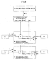
- FIG. 10 is a diagram showing the control system of the single-stand rolling mill S100.
- the single-stand rolling mill S100 has in its entry side an entry tension reel 2 (hereinafter, referred to as 'entry TR2') to feed a material to be rolled to the entry side of the rolling mill 1 so as to make such material inserted into such side and in its exit side an exit tension reel 3 (hereinafter, referred to as 'exit TR3') to wind up the material to be rolled u rolled by the rolling mill 1 with regard to the rolling direction (shown with an arrow in FIG. 10 ) of the rolling mill that is the roll pair.
- 'entry TR2' entry tension reel 2
- 'exit TR3' exit tension reel 3
- the entry TR2 and the exit TR3 are each driven by an electromotor and an entry TR control device 5 and an exit TR control device 6 are provided for such electromotor and the driving control of the electromotor. According to this arrangement, the rolling by the single-stand rolling mill S100 is performed such that after the material to be rolled u unwound from the entry TR2 is rolled with the rolling mill 1, the material to be rolled in the rolled state is wound up by the exit TR3.
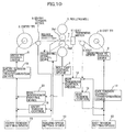
- FIG. 11(A) and FIG. 11(B) are diagrams showing how the reel diameter of the entry TR2 and the exit TR3 respectively changes according as the rolling operation progresses from its initial stage.
- the coil diameter of the entry TR2 is large, the state of which is shown in FIG. 12(A) .
- the coil diameter of the exit TR3 is large, the state of which is shown in FIG. 12(B) .
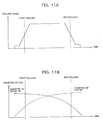
- FIG. 13 is a schematic diagrams showing the speed control device of the rolls and reels of the rolling mill.
- the rolls and reels of the rolling mill are connected to the electromotor through a metallic shaft called a spindle.
- a speed detector is disposed, in which a current instruction is adjusted such that the detected actual speed corresponds to a speed instruction. As the result of it, the current is controlled so that the torque of the electromotor is adjusted, thereby, the speed control being realized.
- the speed control response is lowered.
- the speed control response gets worse than when the reel diameter is small. Therefore, when the rolling mill 1 accelerates and decelerates, it is hard to accelerate and decelerate the reel whose diameter is large in response thereto. In this way, the gist of the present embodiment lies in responding to the reel diameter changing according to the state of the rolling operation.
- a roll gap control device 7 to control the rolled thickness (product thickness) of the material to be rolled u by altering the roll gap which corresponds to the distance between an upper operational roll Rs1 and a lower operational roll Rs2 and a rolling mill speed control device 4 to control the speed (peripheral velocity of the upper and lower operational rolls Rs1 and Rs2) of the rolling mill 1 are provided.
- a speed instruction is outputted from a rolling speed setting device 10 to the rolling mill speed control device 4 and the rolling mill speed control device 4 exerts the control such that the speed (peripheral velocity of the upper and lower operational rolls Rs1 and Rs2) of the rolling mill 1 is made constant.
- the rolling mill speed control device 4 functions as a rotational control unit of a rolling mill.
- the rolling On the entry side of the rolling mill 1 (on the left-hand side of the rolling mill 1 in FIG. 10 ) and the exit side (on the right-hand side thereof in FIG. 10 ), the rolling is stably and efficiently performed with tension applied to the material to be rolled u. It is an entry tension setting device 11 and an exit tension setting device 12 that calculate the tension required for that purpose.
- an entry tension current transformation device 15 and an exit tension current transformation device 16 determine a value of the current to obtain a torque for each electromotor of the entry TR2 and the exit TR3 required for applying the set tensions on the entry side and the exit side to the material to be rolled u based on the entry and exit tension set values calculated by the entry tension setting device 11 and the exit tension setting device 12 and provide the respective values of the current to the entry TR control device 5 and the exit TR control device 6.
- entry TR control device 5 and the exit TR control device 6 they control the current of each electromotor such that it becomes the respectively imparted currents, so that a predetermined tension is applied to the material to be rolled u by the torque of each electromotor provided to the entry TR2 and the exit TR3.
- the entry tension current transformation device 15 and the exit tension current transformation device 16 calculate the set values of the current (set values of the torque of each electromotor) that result in being the set values of the tension based on the models of the TR (tension reel) mechanical system and the TR (tension reel) control device.
- such controlling model entails an error, so that correction is made to the set values of the tension by an entry tension control 13 and an exit tension control 14 with the actual tensions measured by an entry tension meter 8 and an exit tension meter 9 respectively disposed on the entry side and the exit side of the rolling mill 1 and the corrected values are imparted to the entry tension current transformation device 15 and the exit tension current transformation device 16.
- the entry tension current transformation device 15 and the exit tension current transformation device 16 modify the values of the current that are set for the entry TR control device 5 and the exit TR control device 6.
- an exit thickness control device 18 controls the roll gap control device 7 based on the actual thickness detected by an exit thickness meter 17, thereby, the roll gap which is the interval between the rolls of the rolling mill 1 being controlled so as to make the thickness on the exit side (on the right-hand side of the rolling mill 1 in FIG. 1 ) of the rolling mill 1 controlled.
- the exit TR3 and the entry TR2 used for winding up and unwinding the material to be rolled in the single-stand rolling mill are controlled by the constant torque control in which the torque generated by each electromotor is made constant.
- the current instruction for each electromotor is corrected based on the actual tensions detected by the entry tension meter 8 and the exit tension meter 9, thereby the control to make the tension applied to the material to be rolled u constant being exerted.
- the torque of each electromotor of the entry TR2 and the exit TR3 respectively is provided by an electromotor current, so that there are some cases where the constant torque control might be referred to as the constant current control.
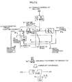
- FIG. 14 is a conceptual diagram showing the rolling phenomenon between the entry TR2 of the single-stand rolling mill S100 and the rolling mill 1.
- J denotes the moment of inertia (kg ⁇ m2) of the entry TR2.
- the electromotor torque 22 is a negative value because it is applied reversely to the rotational direction of the entry TR while the tension torque 25 is a positive value because it is applied to the rotational direction thereof.
- M is a mill constant M(kN/m); Q is a plasticity constant Q (kN/m); and ( ⁇ P/ ⁇ Tb)/(M+Q) is an influence coefficient (kb) to the exit thickness associated with the fluctuation of a rolling load P(kN) according to the fluctuation of the entry tension Tb.
- the mass flow constant law is known as the basic formula of rolling control of the rolling mill 1. This is expressed with the following formula (1) based on the fact that the material to be rolled u continues from the entry side of the rolling mill 1 (on the left-hand side of the rolling mill 1 in FIG. 10 ) to the exit side thereof (on the right-hand side thereof in FIG. 10 ).
- H ⁇ V e h ⁇ V o in which H is an entry thickness of the rolling mill 1; h is an exit thickness of the rolling mill 1; V e is an entry speed of the rolling mill 1; and V o is an exit speed of the rolling mill 1.
- the exit thickness fluctuates when the entry speed fluctuates, provided that the entry thickness is constant.
- the entry speed corresponds to the entry TR speed.
- the entry TR2 changes the entry TR speed 20 such that the tension torque 25 corresponds to the electromotor torque 22, but such change is caused by the inertia of the entry TR2, the rolling mill 1 and the rolling phenomenon, so that there is no control means to control the change of the entry TR speed 20.
- the rolling mill entry speed 21 (speed of the material to be rolled u on the entry side of the rolling mill 1) changes so as to generate a deviation ⁇ Tb of the entry tension 24.
- the entry TR speed 20 changes, but by the change, resulting in an exit thickness fluctuation.
- An entry tension suppression system 27 managed by the entry TR2 sometimes entails a large time constant according to the rolling conditions, so that there are some cases where it might cause the fluctuation with large undulation in the exit thickness.
- the entry tension 24 is also suppressed by the rolling phenomenon.
- the rolling load P of the rolling mill 1 fluctuates, along with which the rolling mill entry speed 21 fluctuates.
- the entry tension 24 fluctuates also by such entry tension rolling phenomenon system 28.
- the response of the entry tension rolling phenomenon system 28 is far faster than that of the entry tension suppression system 27, so that the entry rolling phenomenon as shown in FIG. 14 can be converted into that shown in FIG. 15 .
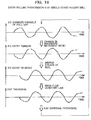
- the relationship among the changed variable of the roll gap 23, the entry tension 24 (Tb), the entry TR speed 20 and the exit thickness is shown in FIG. 16 .
- the entry speed of the rolling mill 1 changes and the entry tension 24 changes.
- the entry TR speed 20 changes by the movement of the entry TR due to its inertia, since the entry TR2 is under the constant torque control.
- the exit thickness control device 18 manipulates the changed variable of the roll gap 23 to make the exit thickness constant. Such series of events continuing, the exit thickness results in vibrating as shown in FIG. 16 .
- exit thickness meter 17 is disposed away from the rolling mill 1, there is a time lag until the exit thickness which is controlled by the exit thickness control device 18 is detected, but when such time lag is sufficiently short against the period of vibration of the exit thickness, it can be ignored.
- a tension speed control means 42 is provided to exert the control such that the tension between the tension reel and the rolling mill is maintained at a value as desired while to prioritize to make the speed of the tension reel constant against deviation from the set value of tension within the predetermined range and to suppress the fluctuation in the speed of the tension reel without correcting the tensional deviation.
- a tension speed control means 42 is provided to exert the control such that the tension between the tension reel and the rolling mill is maintained at a value as desired while to prioritize to make the speed of the tension reel constant against deviation from the set value of tension within the predetermined range and to suppress the fluctuation in the speed of the tension reel without correcting the tensional deviation.
- FIG. 17 is a diagram showing the relationship between such control elements and controlled variables in the case of the single-stand rolling mill.
- the rolling phenomenon of the single-stand rolling mill is as shown in FIG. 18 , the conceptual illustration of which is shown in FIG. 17 .
- control elements comprise the changed variable of the roll gap 23, and the entry TR speed 20 defined as the transferring speed of the material to be rolled.
- controlled variables comprise the rolling mill exit thickness 26 and entry tension 24.
- the changed variable of the roll gap 23 is changed, the change of the exit thickness 26 due to the (roll gap to exit thickness) influence coefficient 503 and the change of the entry tension 24 due to the (roll gap to entry tension) influence coefficient 501 happen.
- the entry TR speed 20 is changed, the change of the entry tension 24 due to the (entry TR speed to entry tension) influence coefficient 502 and the change of the exit thickness 26 due to the (entry TR speed to exit thickness) influence coefficient 504 happen.
- the control in terms of the exit thickness 26 of the rolling mill is exerted by the exit thickness control device 18 changing the roll gap 23. Further, the control in terms of the entry tension 24 is exerted by the entry tension suppression system 27 changing the entry TR speed 20 as shown in FIG. 14 .
- the thickness control device 18 might manipulate the roll gap 23 to control the exit thickness 26, the entry tension 24 largely fluctuates.
- the entry tension suppression system 27 changes the entry TR speed 20, it causes the exit thickness 26 to largely fluctuate.
- the thickness control device 18 manipulates the roll gap 23, with the result that the state where the exit thickness 26, the entry tension 24, the entry TR speed 20 and the roll gap 23 vibrate with the same period occurs.
- the entry rolling phenomenon of the single-stand rolling mill is as shown in FIG. 15 .
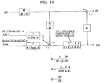
- the similar block diagram to FIG. 17 is shown in FIG. 19 , which is prepared on the basis that the entry tension suppression system 27 by the entry TR2 is removed and the entry TR speed 20 and the changed variable of the roll gap 23 are defined as control elements and the exit thickness 26 and the entry tension 24 are defined as controlled variables.
- the entry tension rolling phenomenon system 28 shown in FIG. 14 is converted into that shown in FIG. 15
- the entry tension rolling phenomenon system 28 is bundled into an entry tension influence coefficient 101.
- the primary delay time constant Tr omitted on the ground that a response time is amply short in comparison with the entry tension suppression system 27 by the entry TR2 is left as it is.
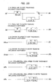
- the influence coefficients 111, 112, 113 and 114 shown in FIG. 20 are obtained.
- V e corresponds to the entry TR speed 20 and h corresponds to the exit thickness 26 of the rolling mill, so that when the exit thickness 26 is small and the entry TR speed 20 is fast, the (entry TR speed to exit thickness) influence coefficient 114 and the (entry TR speed to entry tension) influence coefficient 112 become small. Further, the primary delay time constant Tr included in the entry tension influence coefficient 101 becomes small.
- the (roll gap to exit thickness) influence coefficient 113 becomes small and the response of the (roll gap to entry tension) influence coefficient 111 becomes fast.
- the exit thickness 26 is small and the entry TR speed 20 is fast
- the exit thickness 26 of the rolling mill becomes hard to change while the entry tension becomes easy to change. That is to say, the (roll gap to entry tension) influence coefficient 111 becomes larger than the (roll gap to exit thickness) influence coefficient 113. Further, upon the entry TR speed being manipulated, the entry tension 24 and the exit thickness 26 become hard to change as well.
- the rolling phenomenon term kb also changes according to the rolling speed and the exit thickness, but when the rolling phenomenon term kb becomes large, the (entry TR speed to entry tension) influence coefficient 112 becomes smaller than the (entry TR speed to exit thickness) influence coefficient 114.
- the exit thickness 26 and the entry tension 24 can be stably controlled by adopting a speed thickness control device 50 to control the exit thickness 26 with the entry TR speed 20 and a rolling reduction tension control 51 to control the entry tension 24 with the roll gap 23.
- a speed thickness control device 50 to control the exit thickness 26 with the entry TR speed 20
- a rolling reduction tension control 51 to control the entry tension 24 with the roll gap 23.
- it requires that the entry TR2 conventionally operated under the constant torque control (under the constant current control) be operated under the constant speed control for a change.
- the entry tension suppression system 27 as shown in FIG. 15 turns out to be the primary delay system of the time constant Tq by equivalent conversion.
- the time constant Tq is in proportion to the entry TR speed 20 and in disproportion to the exit thickness 26 of the rolling mill while being in proportion to the rolling phenomenon term kb. Accordingly, when the rolling phenomenon term kb becomes large, the time constant Tq of the entry tension suppression system 27 becomes large, so that the response of the entry tension suppression system 27 is deteriorated. Further, in this case, because the (roll gap to entry tension) influence coefficient 111 as shown in FIG. 17 does not become large, it is considered that the stable control is feasible with the thickness control by the conventional roll gap 23 and the tension control by the entry tension suppression system 27.
- the exit thickness h of the rolling mill 1 can be controlled by changing the entry speed Ve of the rolling mill 1 with the entry TR2 speed, but it is also possible to control the exit thickness h by changing the roll speed Vr of the rolling mill 1.
- b denotes a backward movement ratio of the material to be rolled while f denotes a forward movement ratio thereof.
- the entry tension Tb of the rolling mill 1 is expressed with the following formula (3) while the exit tension Tf thereof is expressed with the following formula (4), in which the speed of the entry TR2 is defined as Vetr while that of the exit TR3 is defined as Vdtr.
- Tb Gb ⁇ ⁇ Vr ⁇ 1 + b ⁇ Vetr dt
- Tf Gf ⁇ ⁇ Vdtr ⁇ Vr ⁇ 1 + f dt
- FIG. 22 is a diagram showing the influence brought by the speed of the rolling mill 1 being changed.
- the speed Vetr of the entry TR2 which corresponds to the entry speed is changed by ⁇ Vetr
- the mass flow constant law turns out to be the following formula (7).
- H ⁇ Vetr + ⁇ Vetr h + ⁇ h ⁇ V 0
- the large coil diameter of the entry TR2 in turn means that the speed responsivity can be further enhanced by manipulating the speed of the exit TR3 than by manipulating the speed of the entry TR2 on the ground that the coil diameter of the exit TR3 is small as shown in FIG. 12(A) so that its moment of inertia is small.
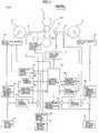
- FIG. 1 The control system of the single-stand rolling mill embodied in the present invention to realize such stable control is shown in FIG. 1 .
- an operation instruction ⁇ S AGC to the roll gap is generated by the rolling reduction thickness control 61 and an operation instruction ⁇ V ETRAGC to the entry TR speed and an operation instruction value ⁇ V MILLAGC to the rolling mill 1 are generated.
- an operation instruction ⁇ V ETRAGC to the entry TR speed and an operation instruction value ⁇ V MILLATR to the rolling mill 1 are generated by the speed tension control 63 and an operation instruction ⁇ S ATR to the roll gap is generated by the rolling reduction tension control 64.
- the addition of a control output from the entry tension control 13 to manipulate the entry tension set value by the deviation between the actual entry tension and the entry tension set value to the entry tension set value by the entry tension setting device 11 is transformed by the entry tension current transformation device 15 as a current instruction to the entry TR2 for the preparation of the current instruction to the entry TR control device 66.
- a control method selection device 70 selectively determines which control methods mentioned above A), B), C), B') and C')should be applied to abate at the maximum the exit thickness fluctuation and the entry tension fluctuation according to the rolling conditions and outputs a roll gap manipulation instruction to the roll gap control device 7 based on the selection result.
- a speed manipulation instruction is outputted to the entry TR speed instruction device 65.
- the entry TR speed instruction is prepared based on an entry TR reference speed outputted from a reference speed setting device 19 and the changed variable of the entry TR speed from the control method selection device 70 so as to be outputted to the entry TR control device 66.
- the control method selection device 70 When the roll speed of the rolling mill 1 is manipulated, the control method selection device 70 outputs a speed manipulation instruction to a rolling mill speed instruction device 81.
- the rolling mill speed instruction device 81 prepares a rolling mill speed instruction based on a rolling mill reference speed outputted from the reference speed setting device 19 and the changed variable of the rolling mill speed from the control method selection device 70 and outputs the rolling mill speed instruction to the rolling mill speed control device 4.
- the entry TR control device 66 there are an operating mode in which the constant torque control (constant current control) according to a current instruction is performed and another operating mode in which the constant speed control according to a speed instruction is performed, which modes are switched over to each other in practical use according to the instruction from the control method selection device 70.
- the entry TR control device 66 functions as a reel rotation control unit.
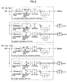
- FIG. 2 shows one example of the block diagram representing the rolling reduction thickness control 61, the speed thickness control 62, the speed tension control 63 and the rolling reduction tension control 64.
- This is just one example of various control systems, so that the other methodical control systems are also applicable.
- the respective control systems are under Integral Control (I Control), but they may be under Proportional Integral Control (PI Control) or Proportional Integral Differential Control (PID Control).
- I Control Integral Control
- PI Control Proportional Integral Control
- PID Control Proportional Integral Differential Control
- a control output ⁇ S AGC is derived from the deviation between an output after the integral and the previous value.
- the speed thickness control 62 is arranged under Integral Control (I Control) in which the exit thickness deviation ⁇ h is rendered into an input and the input exit thickness deviation multiplied by an adjustment gain and a transformation gain from the exit thickness deviation to the entry TR or the mill speed of the rolling mill 1 is integrated.
- a control output expressed with the following formula (15) or (16) is derived from the deviation between an output after the integral and the previous value.
- M denotes a mill constant while Q denotes a plasticity constant of the material to be rolled.
- the speed thickness control instruction is outputted as a speed change ratio against the set speed.
- a control output ⁇ S ATR is derived from the deviation between an output after the integral and the previous value.
- the speed tension control 63 is arranged under Integral Control (I Control) in which the entry tension deviation ⁇ Tb is rendered into an input and the input entry tension deviation ⁇ Tbmultiplied by an adjustment gain and a transformation gain from the entry tension deviation ⁇ Tb to the entry TR or the mill speed of the rolling mill 1 is integrated.
- I Control Integral Control
- a control output expressed with the following formula (17) or (18) is derived from the deviation between an output after the integral and the previous value.
- FIG. 3 shows the synopsis of the control method selection device 70.
- the control method selection device 70 comprises an optimum control method determination device 71 and a control output selection device 72. Which control method among the aforesaid A), B), C), B') and C') is adopted is determined by the optimum control method determination device 71 while which output is adopted among the rolling reduction thickness control 61, the speed thickness control 62, the speed tension control 63 and the rolling reduction tension control 64 is selected by the control output selection device 72, so that a control instruction is outputted to the roll gap control device 7, the entry TR speed instruction device 65, the entry TR control device 66 and the rolling mill speed instruction device 81 respectively.
- the optimum control method determination device 71 functions as a control mode determination unit.
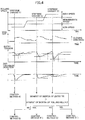
- FIG. 4 shows the operational summary of the optimum control method determination device 71.
- the tension control under rolling reduction and the thickness control under reel speed are performed by means of the control method C) while the thickness control under rolling reduction and the entry tension control to manipulate the TR speed are performed by means of control method B) when a tension modification time constant of the entry tension suppression system 27 is large.
- the control method A) which is conventionally implemented is selected.
- the control method B') or C') to manipulate the rolling mill speed is selectively adopted for the tension control and the thickness control.
- speed is adopted that of the entry TR2 or that of the rolling mill 1
- it may be predetermined that the speed of the rolling mill 1 is manipulated when the moment of inertia of the entry TR 2 including its coil is X times (e.g. twice) as large as the moment of inertia of the speed control system of the rolling mill 1, by way of one example.
- how to set X times it is determined based on the deviational condition of the exit thickness at the actual rolling operation.
- the moment of inertia of the entry TR2 including its coil can be determined based on the reel diameter of the entry TR2 including its coil. Then, the reel diameter of the entry TR2 becomes smaller according as the material to be rolled is unwound while the entry TR2 rotates.
- the reel diameter of the entry TR2 according to the progress of the rolling operation can be calculated based on the number of revolutions of a motor to rotate the entry TR2 and the thickness of the material to be rolled, by way of some examples.
- the control method selection device 70 calculates the reel diameter of the entry TR2 in a real time manner according to the progress of the rolling operation and further calculates the moment of inertia of the entry TR2 including its coil according to the result of such calculation of the reel diameter.
- the moment of inertia of the entry TR2 including its coil calculated in this way is compared with a threshold value defined based on the moment of inertia of the speed control system of the rolling mill 1. As the result of such comparison, when the moment of inertia of the entry TR2 including its coil is larger than the threshold value, the speed of the rolling mill 1 is controlled whereas the speed of the entry TR2 is controlled when it is less than the threshold value.
- the reel diameter of the imaged entry TR2 may be determined by processing the images of the actual entry TR2 captured in a real time.
- the reel diameter as mentioned above that most contributes to the calculation result of the moment of inertia, so that it may be arranged such that a predetermined threshold value is established for the reel diameter and such threshold value is compared with the reel diameter of the entry TR2 on behalf of determining the moment of inertia and comparing such determined moment of inertia with a threshold value.
- the rolling speed is changed in a stepwise manner from a low speed via an intermediate speed to a high speed.
- This stepwise change of the rolling speed is executed to select any one of the aforementioned five control methods.
- the rolling speed is raised in a stepwise manner as shown in FIG. 4 as well.
- the operation shown in FIG. 4 is executable along with the regular rolling operation, which is executable without deteriorating the productivity.
- the changed variable of the entry tension and that of the exit thickness immediately after the roll gap is changed in a stepwise manner are measured and which the (roll gap to entry tension) influence coefficient 114 or the (roll gap to exit thickness) influence coefficient 112 is greater is determined.
- the response time of the entry tension suppression system 27 is determined from the entry tension change when the roll gap is operated in a stepwise manner.
- a low speed zone, an intermediate zone and a high speed zone are defined according to the rolling speed.
- This definition may be such that the rolling speed is divided equally into three parts up to the maximum speed or it is divided according to the other appropriate criteria.
- the roll gap is subjected to a stepwise disturbance. Subjecting the roll gap to such disturbance causes the entry tension and the exit thickness to be fluctuated.
- the parameters dTb, dh and Tbr are determined. Those parameters can be determined through signal processing from the fluctuation conditions of the actual values in the time direction. Based on the largeness relationship among the determined parameters dTb, dh and Tbr and the largeness relationship between the moment of inertia of the entry TR2 and that of the rolling mill 1, any one of the control methods A), B), C), B') and C') is selected.
- any one of the control methods A), B) and C is selected based on the comparison between a value calculated based on the aforementioned parameters dTb, dh and Tbr and a prescribed threshold value. For example, when a value calculated by the fraction of (dh/href)(dTb/Tbref) is a value based on which the control method C) is selected and corresponds to its prescribed threshold value or smaller, according to the comparison between the moment of inertia of the entry TR2 multiplied by a coefficient X and that of the rolling mill 1 multiplied by such coefficient, any one of the control method C) and C') is selected.
- Tbr is a value based on which the control method B) is selected and corresponds to its prescribed threshold value or larger
- any one of the control methods B) and B') is selected according to the comparison between the moment of inertia of the entry TR 2 and that of the rolling mill 1.
- the value based on which the control method C) is selected the value based on which the control method B) is selected and the coefficient X, they may be preliminarily set through the past actual values or the simulation of the rolling mill and as such.
- control method A) is selected as an optimum control method for a low speed
- control method B) or B') is selected as an optimum control method for the intermediate speed
- control method C) or C') is selected as an optimum control method for a high speed.
- the control method selection device 70 executes such optimum control method determination procedures and switches over the control method to the determined optimum control method.
- control method B) or B') and control method C) or C' there are some cases where due to the fact that there is difference in control method of the entry TR among control method A), control method B) or B') and control method C) or C'), they might not be switched over to one another during the rolling operation.
- the rolling operation is continued according to the control method A), and the control method may be switched over to one another when the material to be rolled which is the same type of steel and has the same width as the previous one has arrived.
- the determined optimum control method is stored in the database in which the type of steel for the material to be rolled, the exit thickness and the rolling speed are retrievable, in which when the same type of the material to be rolled is rolled next time, it is controlled according to the optimum control method stored in the database.
- FIG. 6 An example of the stored data in the database is illustrated in FIG. 6 .
- the control method A), control method B) or B') and control method C) or C') might not be switched over to one another during the rolling operation, but the control method B) or B') can be adopted on behalf of the control method A).
- the control method B) or B') can be adopted on behalf of the control method A).
- a stable and high-precision rolling is feasible over the entire speed zones by selecting the control method B) or B') for a low speed while by selecting control method C) or C') in a high speed.
- the aforementioned method is just one example of the optimum control method determination procedures, so that the other methods are also adoptable.
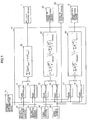
- FIG. 7 shows the operational summary of a control output selection device 72.
- the control output selection device 72 outputs from the rolling reduction thickness control 61, the speed thickness control 62, the speed tension control 63 and the rolling reduction tension control 64 as well as the control method selection result from the optimum control method determination device 71 are rendered into inputs and a control instruction is outputted to the roll gap control device 7, the entry TR speed instruction device 65, the entry TR control device 66 and the rolling mill speed instruction device 81 respectively.
- an output from the rolling reduction thickness control 61, the speed thickness control 62, the speed tension control 63 and the rolling reduction tension control 64 respectively is inputted to the gain controllers 73, 74, 75, 76, 77 and 78.
- Those gain controllers 73 to 78 are signal adjustment units in which the output of the rolling reduction thickness control 61, the speed thickness control 62, the speed tension control 63 and the rolling reduction tension control 64 respectively is outputted with a gain.
- the gains of the gain controllers 73 to 78 are adjusted based on the control method selection result from the optimum control method determination device 71.
- the output from the rolling reduction thickness control 61 is subjected to integral processing so as to be outputted to the roll gap control device 7. Further, the constant torque control mode selection is outputted to the entry TR control device 66.
- the gain of the gain controllers 74 to 78 respectively is set at zero as well as the gain of the gain controller 73 is adjusted, thereby, being set such that the output from the rolling reduction thickness control 61 is subjected to integral processing by means of an integral processing unit 82.
- the constant torque control mode selection is outputted to the entry TR control device 66.
- the entry TR control device 66 functions as a tension reel torque control unit.
- the output from the rolling reduction thickness control 61 is subjected to integral processing so as to be outputted to the roll gap control device 7 as well as the output from the speed tension control 63 is subjected to integral processing so as to be outputted to the entry TR speed instruction device 65 or the rolling mill speed instruction device 81.
- the gain of the gain controllers 74, 75 and 77 respectively is set at zero as well as the gain of the gain controllers 73, 76 and 78 respectively is adjusted, thereby, being set such that the output from the rolling reduction thickness control 61 is subjected to integral processing by means of the integral processing unit 82 as well as the output from the speed tension control 63 is subjected to integral processing by means of the integral processing unit 83 or 84.
- the output from the speed thickness control 62 is subjected to integral processing so as to be outputted to the entry TR speed instruction device 65 or the rolling mill speed instruction device 81 as well as the output from the rolling reduction tension control 64 is subjected to integral processing so as to be outputted to the roll gap control device 7.
- the gain of the gain controllers 73, 76 and 78 respectively is set at zero as well as the gain of the gain controllers 74, 75 and 77 respectively is adjusted, thereby, being set such that the output from the rolling reduction tension control 64 is subjected to integral processing by means of the integral processing unit 82 as well as the output from the speed thickness control 62 is subjected to integral processing by means of the integral processing unit 83 or 84.
- control path in connection with the integral processing unit 82 and the roll gap control device 7 functions as the roll gap control unit. Further, the control path in connection with the integral processing unit 83 and the entry TR speed instruction device 65 or that in connection with the integral processing unit 84 and the rolling mill speed instruction device 81 functions as a speed control unit.
- the control methods A), B), C), B') and C') can be alternatively switched over to one another e.g., according to the rolling speed even during the rolling operation.
- the entry TR speed instruction device 65 as shown in FIG. 8 , with the entry TR speed V ETR prepared at the reference speed setting device 19 with the rolling mill entry backward movement ratio b taken into account based on the rolling mill speed V MILL determined at the rolling speed setting device 10 by the manual operation of an operator, the entry TR speed instruction V ETRref is prepared with a control instruction from the control method selection device 70 so as to be outputted to the entry TR control device 66.
- the rolling mill speed instruction V MILLref is prepared with a control instruction from the control method selection device 70 based on the rolling mill speed V MILL determined at the rolling speed setting device 10 by the manual operation of an operator so as to be outputted to the rolling mill speed control device 4.
- FIG. 9 shows the synopsis of the entry TR control device 66.
- the current to the entry TR2 is outputted with the entry TR speed instruction V ETRref from the entry TR speed instruction device 65, the current instruction I ETRset from the entry tension current transformation device and the constant torque control mode from the control method selection device 70 rendered into inputs.
- the entry TR2 comprises a TR mechanical device and an electromotor to operate such device, in which the current to the entry TR2 denotes that to the electromotor.
- the entry TR control device 66 comprises a P control 661 and an I control 662 to prepare a current instruction such that the speed instruction V ETRref matches the actual speed V ETRfb and a current control 663 to exert the control such that the prepared current instruction I ETRref matches the current I ETRfb flowing through the electromotor of the entry TR2.
- the I control 662 is replaced with an entry TR current set value I ETRset from the entry tension current transformation device 15.
- the P control 661 and the I control 662 are modified according to the entry TR speed deviation.
- control method optimum for the exit thickness control and for the entry thickness control to be selected with the control methods A), B), C), B') and C') switched over to one another according to the rolling conditions, so that the exit thickness precision and the operational efficiency largely improve.
- the rotational speed of the entry TR2 is assumed to be a control element when the speed control is exerted, but when the reel diameter of the entry TR2 is large, its moment of inertia is large while the control response is poor, so that the mill speed of the rolling mill 1 is controlled as well as the rotational speed of the exit TR3 is placed under successive control accordingly.
- This permits the oscillation of the controlled variables caused by controlling the control element whose control response is poor to be prevented.
- the exit thickness is controlled by adjusting the entry TR2 speed and the tension of the material to be rolled is controlled by adjusting the roll gap.
- the adjustment of the entry TR2 speed might affect the tension of the material to be rolled.
- the adjustment of the roll gap might affect the exit thickness.
- non-interference control be exerted.
- the mode of exerting such non-interference control lies in the step of inputting ⁇ S determined by the integral processing unit 82 to the roll gap control device 7 as well as inputting an influence degree to the speed determined based on ⁇ S and the rolling conditions to the integral processing unit 83 e.g., at the control output selection device 72 as shown in FIG. 7 .
- an output signal to the entry TR speed instruction device 65 is calculated with the influence to the thickness or tension caused by the roll gap adjustment taken into account. In other words, it allows the influence to the thickness or tension caused by the roll gap adjustment to be cancelled.
- a module to calculate the influence degree to the speed determined based on the aforementioned ⁇ S and rolling conditions functions as a roll gap adjustment interference prediction unit.
- 1+( ⁇ V/V) determined by the integral processing unit 83 is inputted to the entry TR speed instruction device 65 as well as the influence degree to the thickness or tension determined based on 1+( ⁇ V/V) and the rolling conditions is inputted to the integral processing unit 82.
- an output signal to the roll gap control device 7 is calculated with the influence to the tension caused by the tension reel speed adjustment. In other words, it allows the influence to the thickness or tension caused by the tension reel speed adjustment to be cancelled.
- a module to calculate the influence degree to the tension determined based on the aforesaid 1+( ⁇ V/V) and the rolling conditions functions as an interference prediction unit.
- Such non-interference control is especially effective in the case of concurrently using the control methods A), B), C), B') and C') according to the aforesaid gain control.
- the control methods C) and B) are intermixed, the case where the control method C) is executed by 80% and the control method B) is executed by 20% is presented herein.
- the gain of the gain controller 74 to adjust the output of the rolling reduction tension control 64 is defined as 80% while that of the gain controller 73 to adjust the output of the rolling reduction thickness control 61 is defined as 20%.
- the gain of the gain controller 75 to adjust the output of the speed thickness control 62 is defined as 80% while that of the gain controller 76 to adjust the output of the speed tension control 63 is defined as 20%.
- the rolling conditions are mainly controlled by the influence of the control method C), so that it can be said that the influence to the thickness caused by the roll gap adjustment and the influence to the tension caused by the tension reel speed are minor. Accordingly, in such a case, the control conditions are facilitated by turning off the non-interference control.
- the gain of the gain controller 74 to adjust the output of the rolling reduction tension control 64 is defined as 60% while that of the gain controller 73 to adjust the output of the rolling reduction thickness control 61 is defined as 40%.
- the gain of the gain controller 75 to adjust the output of the speed thickness control 62 is defined as 60% while that of the gain controller 76 to adjust the output of the speed tension control 63 is defined as 40%.
- the rolling conditions are rather controlled by the control method C), but they are more or less controlled by the control method B) as well, so that it can be said that the influence to the thickness caused by the roll gap adjustment and that to the tension caused by the tension reel speed adjustment should be taken into account. Accordingly, in such a case, a favorable control is executable by turning on such non-interference control.
- Such turning-on and off of the non-interference control can be determined based on the ratio of the gain of the gain controller 73 to that of the gain controller 74 and the ratio of the gain of the gain controller 75 to that of the gain controller 76.
- the non-interference control is turned on judging that the control of the gain with such lower value cannot be overlooked.
- the gain with such lower value is a prescribed value or lower
- such non-interference control is turned off judging that the control influenced by the gain with such lower value can be overlooked.
- Such prescribed value is exemplified herein as 20% or 30%.
- the case where the entry tension meter 8 is provided to control the tension is exemplified.
- control methods A), B), C), B') and C') are switched over to one another, but it is also possible to select any one of those control methods beforehand according to the machinery specifications and the product specifications of the materials to be rolled and to continuously use such selected method.
- the database explained with reference to FIG. 6 is adoptable.
- control method for the entry TR2 is described, but the same arrangement as for the entry TR2 is applicable to the control method for the exit TR3.
- the influence to the thickness given by the exit tension is larger according to the types of the rolling mills and the materials to be rolled, there are some cases where it might be more effective to manipulate the exit TR.
- the case where the entry TR2 is operated under the constant speed control while the exit TR3 is operated under the constant torque control is described, but it is also possible to operate the exit TR3 under the constant speed control and to execute the exit tension control with the speed control.
- the speed instruction of the exit TR3 it is possible to execute the entry tension control or the exit thickness control of the rolling mill with the occurrence of the exit tension fluctuation of the rolling mill suppressed to the minimum by considering an extent to which the speed instruction is modified for the rolling mill 1 as the successive extent.
- the tandem rolling mill having a plurality of stands is adoptable just provided that a tension reel is disposed on the entry side or the exit side thereof.
- the tandem rolling mill having a plurality of stands regarded as the single rolling mill, it is possible to execute the same control as described above on the tension between the foremost rolling mill stand and the tension reel and on that between the rearmost rolling mill stand and the tension reel among the plurality of rolling mill stands.
- FIG. 23 is a block diagram showing the hardware configuration of the information processing device constituting the rolling control device embodied herein.
- the rolling control device embodied herein has the same configuration as that of information processing terminals such as a general server, PC (Personal Computer) or the like.
- a CPU Central Processing Unit
- a RAM Random Access Memory
- ROM Read Only Memory
- HDD Hard Disk Drive
- I/F 205 an I/F 205
- an LCD Liquid Crystal Display
- the CPU 201 serves as calculating means for controlling the operations of the rolling control device as a whole.
- the RAM 202 is a volatile storage medium capable of high-speed reading and writing of information, and used as a working area when the CPU 201 processes the information.
- the ROM 203 is a read-only nonvolatile storage medium, in which programs, such as firmware, are stored.
- the HDD 204 is a nonvolatile storage medium capable of reading and writing of information, in which an OS (Operating System), various kinds of control programs, application programs, etc., are stored.
- the I/F 205 connects and controls the bus 208 and various kinds of hardware, networks, etc.
- the I/F 205 is also used as an interface for the respective devices to exchange information or input information to the rolling mill.
- the LCD 206 is a visual user interface for an operator to check the state of the rolling control device.
- the operating unit 207 is a user interface, such as a keyboard or mouse, for an operator to input information into the rolling control device.
- the CPU 201 carries out an operation according to the program stored in the ROM 203 and the HDD 204 or a recording medium such as an optical disk, which is not illustrated, and read by the RAM 202, thereby constituting a software control unit.
- the functions of the rolling control device embodied herein are realized by the combination of the software control unit configured in this manner and the hardware.
- each function is all incorporated in the rolling control device, but such entire functions may be realized in one information processing device or each function may be realized dispersively in a plurality of information processing devices.
- the case where which of the entry TR2 or the rolling mill 1should be decided as a control element for the speed control through the comparison between the resulting moment of inertia of the entry TR2 calculated by some means and the moment of inertia of the rolling mill 1 is exemplified.
- the essence of such decision depends on whether the control response is good or not when a control instruction value is varied. Accordingly, when the entry TR control device 66 varies a control instruction value that it outputs to control the entry TR2, the responsivity may be decided based on the period by which the control result is stabilized according to such varied instruction value.
- the responsivity of the rolling mill 1 does not fluctuate in particular, but the responsivity of the entry TR 2 improves by its reel diameter becoming smaller so as to make its moment inertia smaller according as the rolling operation progresses.
- the rolling mill 1 is initially selected as the control element for the speed control, but such control element is switched over from the rolling mill 1 to the entry TR 2 according as the rolling operation proceeds.
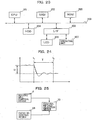
- FIG. 24 is a diagram showing the conception of the responsivity accompanied with the fluctuation of the instruction value of the entry TR2.
- the fluctuation of the instruction value is indicated with a broken line while the state value of the control result is indicated with a solid line.
- the fluctuation of the instruction value is defined as ⁇
- the period by which the state value of the control result is stabilized in pursuit of the instruction value corresponds to a period T from the timing t 1 at which the instruction value has fluctuated to the timing t 2 at which the state value has been stabilized. It is possible to determine whether or not the responsivity is good by checking the ratio of ⁇ to T.
- the entry TR2 is controlled based on the detection result of the entry tension meter 8 as shown in FIG. 1 and the tension set value designated by the entry tension setting device 11, in which there is no 'instruction value' for the rotational speed. Accordingly, there is no value directly corresponding to the broken line as shown in FIG. 24 , so the timing t 1 cannot be determined.
- the factor by which the rotation of the entry TR2 is controlled is when the rotational speed of the rolling mill 1 fluctuates.
- the control speed of the rolling mill 1 fluctuates, it is predicted that the tension of the material to be rolled lying between the entry TR2 and the rolling mill 1 fluctuates, as the result of which the rotational speed of the entry TR2 is controlled.
- the control method selection device 70 acquiring information from the rolling mill speed control device 4 and the entry TR control device 66 respectively, as shown in FIG. 25 .
- the rolling mill speed control device 4 inputs a control value upon controlling the speed of the rolling mill 1 to the control method selection device 70 in a real time manner. This permits the control method selection device 70 to grasp the timing at which the control value against the rolling mill 1 has fluctuated and the resulting fluctuated variable, thereby enabling the timing t 1 and the fluctuated variable as shown in FIG. 24 to be estimated.
- the entry TR control device 66 inputs the state value resulting from the entry TR2 being actually controlled to the control method selection device 70.
- This allows the control method selection device 70 to acquire information indicated with the solid line in FIG. 24 and to calculate the period T by analyzing such information according to the existing method so as to grasp the timing t 2 as shown in FIG. 24 , with the result that the control method selection device 70 can determine the responsivity of the entry TR2 based on the fluctuated variable ⁇ and the period T.
- the control method selection device 70 that determines the responsivity of the entry TR2 in this way discerns whether or not such responsivity is good in a real time manner by comparing the determined result of such responsivity and the prescribed threshold value. Then, when it is determined by the control method selection device 70 that the responsivity of the entry TR2 is better than the prescribed level, the control element for the speed control is switched over from the rolling mill 1 to the entry TR2. That is to say, in FIG. 25 , the control method selection device 70 functions as a control mode determination unit. Such control mode also brings the same advantageous effects as described above.
Landscapes
- Engineering & Computer Science (AREA)
- Mechanical Engineering (AREA)
- Control Of Metal Rolling (AREA)
- Winding, Rewinding, Material Storage Devices (AREA)
Claims (10)
- Dispositif de commande de laminage comprenant :une unité de commande d'écartement des rouleaux (7) ; etune unité de commande de vitesse (4) qui commande une vitesse de transfert du matériau à laminer qui est inséré dans un laminoir (1) pour une opération de laminage par le laminoir (1) sur la base d'une épaisseur du matériau à laminer dans l'état laminé,caractérisé en ce quel'unité de commande d'écartement des rouleaux (7) commande un intervalle entre les rouleaux d'une paire de rouleaux sur la base soit d'une tension d'un matériau à laminer qui est inséré dans le laminoir (1) pour une opération de laminage par le laminoir (1) pour laminer le matériau à laminer avec la paire de rouleaux, soit d'une tension du matériau à laminer fourni par le laminoir (1) dans un état laminé ; etl'unité de commande de vitesse (4) commande la vitesse de transfert du matériau à laminer en commandant soit une rotation d'une bobine servant à dérouler et fournir le matériau à laminer par rapport au laminoir, soit une rotation du laminoir (1).
- Dispositif de commande de laminage selon la revendication 1, comprenant en outre
une unité de détermination du mode de commande (70) qui détermine laquelle de la rotation de la bobine ou de la rotation du laminoir (1) est commandée pour commander la vitesse de transfert du matériau à laminer. - Dispositif de commande de laminage selon la revendication 2, dans lequel l'unité de détermination du mode de commande (70) détermine laquelle de la rotation de la bobine ou de la rotation du laminoir (1) est commandée sur la base d'un moment d'inertie de la bobine.
- Dispositif de commande de laminage selon la revendication 2 ou 3, dans lequel l'unité de détermination du mode de commande (70) détermine le moment d'inertie de la bobine sur la base du diamètre de la bobine.
- Dispositif de commande de laminage selon la revendication 4, dans lequel l'unité de détermination du mode de commande (70) détermine le diamètre de la bobine sur la base d'une variable concernant la rotation d'un moteur servant à faire tourner la bobine et de l'épaisseur du matériau à laminer.
- Dispositif de commande de laminage selon la revendication 4, dans lequel l'unité de détermination du mode de commande (70) détermine le diamètre de la bobine sur la base d'une image générée par la capture de la bobine.
- Dispositif de commande de laminage selon la revendication 2, dans lequel l'unité de détermination du mode de commande (70) détermine laquelle de la rotation de la bobine ou de la rotation du laminoir (1) est commandée sur la base d'une réactivité dans le cas où la rotation de la bobine est commandée.
- Dispositif de commande de laminage selon la revendication 7, dans lequel :la bobine est entraînée sous le contrôle d'une unité de commande de rotation de bobine servant à commander la rotation du laminoir (1) sur la base d'une différence entre un résultat détecté d'une tension du matériau à laminer se trouvant entre la bobine et le laminoir (1) et une tension cible désignée ; etl'unité de détermination du mode de commande détermine la réactivité dans le cas où la rotation de la bobine est commandée sur la base d'une période allant du moment à partir duquel une valeur de commande délivrée par l'unité de commande de rotation de bobine pour commander la rotation de la bobine fluctue à celui où la rotation de la bobine est stabilisée conformément à la valeur de commande.
- Dispositif de commande de laminage selon la revendication 8, dans lequel :le laminoir (1) est entraîné sous le contrôle d'une unité de commande de rotation de laminoir servant à commander la rotation du laminoir (1) de sorte qu'il atteigne une vitesse cible désignée ; etl'unité de détermination du mode de commande (70) détermine la réactivité dans le cas où la rotation de la bobine est commandée sur la base de la période allant jusqu'à ce que la rotation de la bobine soit stabilisée et d'une variable ayant fluctué d'une valeur de commande délivrée par l'unité de commande du laminoir servant à commander la rotation du laminoir (1).
- Procédé de commande de laminage, consistant à :commander un intervalle entre les rouleaux d'une paire de rouleaux ; etcommander une vitesse de transfert du matériau à laminer qui est inséré dans le laminoir pour une opération de laminage par le laminoir (1) sur la base d'une épaisseur du matériau à laminer dans l'état laminé,caractérisé en ce quela commande de l'intervalle entre les rouleaux de la paire de rouleaux est basée soit sur une tension d'un matériau à laminer qui est inséré dans un laminoir (1) pour une opération de laminage par le laminoir (1) pour laminer le matériau à laminer avec la paire de rouleaux, soit sur une tension du matériau à laminer fourni par le laminoir (1) dans un état laminé ; etdans lequel, à l'étape consistant à commander la vitesse de transfert du matériau à laminer, soit une rotation d'une bobine servant à dérouler et fournir le matériau à laminer par rapport au laminoir, soit une rotation du laminoir (1) est commandée.
Applications Claiming Priority (1)
| Application Number | Priority Date | Filing Date | Title |
|---|---|---|---|
| JP2014231995A JP6308928B2 (ja) | 2014-11-14 | 2014-11-14 | 圧延制御装置、圧延制御方法および圧延制御プログラム |
Publications (2)
| Publication Number | Publication Date |
|---|---|
| EP3020487A1 EP3020487A1 (fr) | 2016-05-18 |
| EP3020487B1 true EP3020487B1 (fr) | 2017-08-23 |
Family
ID=54477954
Family Applications (1)
| Application Number | Title | Priority Date | Filing Date |
|---|---|---|---|
| EP15193695.2A Active EP3020487B1 (fr) | 2014-11-14 | 2015-11-09 | Dispositif et méthode de commande de laminage |
Country Status (4)
| Country | Link |
|---|---|
| EP (1) | EP3020487B1 (fr) |
| JP (1) | JP6308928B2 (fr) |
| KR (1) | KR101701646B1 (fr) |
| CN (1) | CN105598180B (fr) |
Families Citing this family (10)
| Publication number | Priority date | Publication date | Assignee | Title |
|---|---|---|---|---|
| CN106670242B (zh) * | 2017-02-09 | 2018-05-04 | 广西南南铝加工有限公司 | 在线控制离线带材板形的装置 |
| CN106890855A (zh) * | 2017-02-22 | 2017-06-27 | 肇庆远境自动化设备有限公司 | 一种连轧机组电气传动控制系统 |
| CN107999537B (zh) * | 2018-01-17 | 2023-06-20 | 般若涅利(北京)装备技术有限公司 | 一种抑制辊压后电池极片厚度反弹的装置及相应的方法 |
| JP6966417B2 (ja) * | 2018-12-28 | 2021-11-17 | 株式会社日立製作所 | 圧延制御装置、圧延制御方法、および圧延制御プログラム |
| JP7178920B2 (ja) * | 2019-01-31 | 2022-11-28 | 株式会社日立製作所 | プラント制御装置および圧延制御装置 |
| JP7197027B2 (ja) * | 2020-01-15 | 2022-12-27 | 東芝三菱電機産業システム株式会社 | 圧延制御システムおよび圧延制御方法 |
| CN112077155B (zh) * | 2020-08-04 | 2022-03-18 | 首钢京唐钢铁联合有限责任公司 | 一种轧机轧制冲击扭矩的获取方法和装置 |
| CN112337980A (zh) * | 2020-10-16 | 2021-02-09 | 中冶京诚工程技术有限公司 | 棒线材轧机转速低通滤波方法及装置 |
| CN112974529B (zh) * | 2021-02-20 | 2023-12-12 | 山西太钢不锈钢精密带钢有限公司 | 极薄软态亮面低粗糙度不锈钢带预防表面划伤的卷取方法 |
| CN113210438B (zh) * | 2021-05-20 | 2023-03-24 | 广西北港不锈钢有限公司 | 一种不锈钢冷轧薄板的高速轧制方法 |
Citations (9)
| Publication number | Priority date | Publication date | Assignee | Title |
|---|---|---|---|---|
| JPS6083719A (ja) | 1983-10-12 | 1985-05-13 | Sumitomo Metal Ind Ltd | ストリツプミルの板厚制御方法 |
| EP0435595A2 (fr) | 1989-12-25 | 1991-07-03 | Ishikawajima-Harima Jukogyo Kabushiki Kaisha | Système de vÀ©rification de l'épaisseur pour un laminoir |
| JPH0475711B2 (fr) | 1983-05-21 | 1992-12-01 | Sony Corp | |
| DE10065351A1 (de) | 1999-12-27 | 2001-06-28 | Telepro Inc Eine Ges Nach Den | Kompensationssystem für periodische Stärkeabweichungen |
| EP1952902A1 (fr) | 2005-11-11 | 2008-08-06 | JFE Steel Corporation | Appareil de refroidissement pour bande d'acier laminee a chaud et procede de refroidissement de bande d'acier |
| EP1491268B1 (fr) | 2003-06-25 | 2008-11-26 | Abb Ag | Procédé de laminage à froid de bandes métalliques |
| DE102010013387A1 (de) | 2009-04-01 | 2011-07-14 | Hitachi, Ltd. | Steuervorrichtung und -verfahren für ein Walzwerk |
| CN101602068B (zh) | 2009-07-07 | 2011-08-17 | 东北大学 | 周期性变厚度带材轧制过程中张力的控制方法及控制系统 |
| JP2014113629A (ja) | 2012-12-11 | 2014-06-26 | Hitachi Ltd | 圧延制御装置、圧延制御方法および圧延制御プログラム |
Family Cites Families (8)
| Publication number | Priority date | Publication date | Assignee | Title |
|---|---|---|---|---|
| JPS6083718A (ja) * | 1983-10-12 | 1985-05-13 | Nippon Steel Corp | 冷間圧延機の自動板厚制御方法 |
| JP2003275815A (ja) * | 2002-03-22 | 2003-09-30 | Nippon Steel Corp | 可逆式冷間圧延機におけるコイル径変動補償装置 |
| JP5140607B2 (ja) * | 2009-01-13 | 2013-02-06 | 株式会社日立製作所 | 圧延機の制御装置およびその制御方法 |
| CN101856671B (zh) * | 2009-04-10 | 2013-02-13 | 株式会社日立制作所 | 轧制装置、轧制装置的控制方法及轧制设备 |
| JP2012176428A (ja) | 2011-02-28 | 2012-09-13 | Hitachi Ltd | 圧延制御装置及び圧延制御方法 |
| JP2014011629A (ja) | 2012-06-29 | 2014-01-20 | Sharp Corp | 通信端末 |
| JP6031344B2 (ja) * | 2012-12-05 | 2016-11-24 | 株式会社日立製作所 | 圧延制御装置、圧延制御方法および圧延制御プログラム |
| JP5552179B2 (ja) * | 2013-03-19 | 2014-07-16 | 株式会社日立製作所 | 圧延機の制御装置およびその制御方法 |
-
2014
- 2014-11-14 JP JP2014231995A patent/JP6308928B2/ja active Active
-
2015
- 2015-11-03 KR KR1020150153545A patent/KR101701646B1/ko active IP Right Grant
- 2015-11-06 CN CN201510750707.9A patent/CN105598180B/zh active Active
- 2015-11-09 EP EP15193695.2A patent/EP3020487B1/fr active Active
Patent Citations (10)
| Publication number | Priority date | Publication date | Assignee | Title |
|---|---|---|---|---|
| JPH0475711B2 (fr) | 1983-05-21 | 1992-12-01 | Sony Corp | |
| JPS6083719A (ja) | 1983-10-12 | 1985-05-13 | Sumitomo Metal Ind Ltd | ストリツプミルの板厚制御方法 |
| EP0435595A2 (fr) | 1989-12-25 | 1991-07-03 | Ishikawajima-Harima Jukogyo Kabushiki Kaisha | Système de vÀ©rification de l'épaisseur pour un laminoir |
| DE10065351A1 (de) | 1999-12-27 | 2001-06-28 | Telepro Inc Eine Ges Nach Den | Kompensationssystem für periodische Stärkeabweichungen |
| US6263714B1 (en) | 1999-12-27 | 2001-07-24 | Telepro, Inc. | Periodic gauge deviation compensation system |
| EP1491268B1 (fr) | 2003-06-25 | 2008-11-26 | Abb Ag | Procédé de laminage à froid de bandes métalliques |
| EP1952902A1 (fr) | 2005-11-11 | 2008-08-06 | JFE Steel Corporation | Appareil de refroidissement pour bande d'acier laminee a chaud et procede de refroidissement de bande d'acier |
| DE102010013387A1 (de) | 2009-04-01 | 2011-07-14 | Hitachi, Ltd. | Steuervorrichtung und -verfahren für ein Walzwerk |
| CN101602068B (zh) | 2009-07-07 | 2011-08-17 | 东北大学 | 周期性变厚度带材轧制过程中张力的控制方法及控制系统 |
| JP2014113629A (ja) | 2012-12-11 | 2014-06-26 | Hitachi Ltd | 圧延制御装置、圧延制御方法および圧延制御プログラム |
Non-Patent Citations (2)
| Title |
|---|
| "Conventional Control", 2011, article PITTNER ET AL., XP055492846 |
| "Rolling (Metal- work)", 1978, ISBN: 0-8247-6780-2, article ROBERTS, WILLIAM L.: "Cold rolling of steel (Manufacturing engineering and materials processing", pages: 234 - 235, XP055492835 |
Also Published As
| Publication number | Publication date |
|---|---|
| KR20160057992A (ko) | 2016-05-24 |
| KR101701646B1 (ko) | 2017-02-01 |
| EP3020487A1 (fr) | 2016-05-18 |
| CN105598180B (zh) | 2017-11-21 |
| JP6308928B2 (ja) | 2018-04-11 |
| JP2016093829A (ja) | 2016-05-26 |
| CN105598180A (zh) | 2016-05-25 |
Similar Documents
| Publication | Publication Date | Title |
|---|---|---|
| EP3020487B1 (fr) | Dispositif et méthode de commande de laminage | |
| JP5961103B2 (ja) | 圧延制御装置、圧延制御方法および圧延制御プログラム | |
| EP3025798B1 (fr) | Dispositif et procédé de commande de laminage | |
| CN101856670B (zh) | 滚轧机的控制装置及其控制方法 | |
| WO2012127571A1 (fr) | Appareil de commande de laminage, procédé de commande de laminage et programme de commande de laminage | |
| JP2015112614A (ja) | 圧延制御装置、圧延制御方法および圧延制御プログラム | |
| KR101593812B1 (ko) | 압연 제어 장치, 압연 제어 방법 및 기록 매체 | |
| US9638515B2 (en) | Method for actuating a tandem roll train, control and/or regulating device for a tandem roll train, machine-readable program code, storage medium and tandem roll train | |
| JP6663872B2 (ja) | 圧延機の制御装置、圧延機の制御方法及び圧延機の制御プログラム | |
| JP5552179B2 (ja) | 圧延機の制御装置およびその制御方法 | |
| JP2005254289A (ja) | 圧延機の速度制御方法 | |
| JP6373800B2 (ja) | 圧延制御装置、圧延制御方法および圧延制御プログラム | |
| JP5665328B2 (ja) | 板厚制御方法及び圧延装置 | |
| JP4996889B2 (ja) | 形状制御方法及び制御装置 | |
| JP4964058B2 (ja) | 線材圧延方法及びタンデム圧延装置 | |
| JPH05208204A (ja) | ストリップ圧延における形状制御方法 | |
| JP3255785B2 (ja) | タンデム圧延機における板厚制御方法 | |
| JP7191765B2 (ja) | 圧延機の蛇行抑制方法 | |
| JP2760292B2 (ja) | タンデム圧延機の制御方法 | |
| JPS6132091B2 (fr) | ||
| JPH04361813A (ja) | 圧延ラインにおける圧延材噛込速度制御方法 | |
| JPH0732023A (ja) | 熱間仕上圧延機の多周期制御によるルーパー角度及び張力制御方法 | |
| JPS6083719A (ja) | ストリツプミルの板厚制御方法 | |
| JP4233363B2 (ja) | 板厚制御方法及び装置 | |
| JPH01254301A (ja) | ダルワークロールを用いる冷間圧延方法 |
Legal Events
| Date | Code | Title | Description |
|---|---|---|---|
| PUAI | Public reference made under article 153(3) epc to a published international application that has entered the european phase |
Free format text: ORIGINAL CODE: 0009012 |
|
| 17P | Request for examination filed |
Effective date: 20160115 |
|
| AK | Designated contracting states |
Kind code of ref document: A1 Designated state(s): AL AT BE BG CH CY CZ DE DK EE ES FI FR GB GR HR HU IE IS IT LI LT LU LV MC MK MT NL NO PL PT RO RS SE SI SK SM TR |
|
| AX | Request for extension of the european patent |
Extension state: BA ME |
|
| GRAP | Despatch of communication of intention to grant a patent |
Free format text: ORIGINAL CODE: EPIDOSNIGR1 |
|
| STAA | Information on the status of an ep patent application or granted ep patent |
Free format text: STATUS: GRANT OF PATENT IS INTENDED |
|
| INTG | Intention to grant announced |
Effective date: 20170330 |
|
| RIN1 | Information on inventor provided before grant (corrected) |
Inventor name: HATTORI, SATOSHI |
|
| GRAS | Grant fee paid |
Free format text: ORIGINAL CODE: EPIDOSNIGR3 |
|
| GRAA | (expected) grant |
Free format text: ORIGINAL CODE: 0009210 |
|
| STAA | Information on the status of an ep patent application or granted ep patent |
Free format text: STATUS: THE PATENT HAS BEEN GRANTED |
|
| AK | Designated contracting states |
Kind code of ref document: B1 Designated state(s): AL AT BE BG CH CY CZ DE DK EE ES FI FR GB GR HR HU IE IS IT LI LT LU LV MC MK MT NL NO PL PT RO RS SE SI SK SM TR |
|
| REG | Reference to a national code |
Ref country code: GB Ref legal event code: FG4D |
|
| REG | Reference to a national code |
Ref country code: CH Ref legal event code: EP |
|
| REG | Reference to a national code |
Ref country code: SE Ref legal event code: TRGR |
|
| REG | Reference to a national code |
Ref country code: AT Ref legal event code: REF Ref document number: 920786 Country of ref document: AT Kind code of ref document: T Effective date: 20170915 |
|
| REG | Reference to a national code |
Ref country code: IE Ref legal event code: FG4D |
|
| REG | Reference to a national code |
Ref country code: DE Ref legal event code: R096 Ref document number: 602015004292 Country of ref document: DE |
|
| REG | Reference to a national code |
Ref country code: NL Ref legal event code: MP Effective date: 20170823 |
|
| REG | Reference to a national code |
Ref country code: LT Ref legal event code: MG4D |
|
| REG | Reference to a national code |
Ref country code: AT Ref legal event code: MK05 Ref document number: 920786 Country of ref document: AT Kind code of ref document: T Effective date: 20170823 |
|
| PG25 | Lapsed in a contracting state [announced via postgrant information from national office to epo] |
Ref country code: LT Free format text: LAPSE BECAUSE OF FAILURE TO SUBMIT A TRANSLATION OF THE DESCRIPTION OR TO PAY THE FEE WITHIN THE PRESCRIBED TIME-LIMIT Effective date: 20170823 Ref country code: FI Free format text: LAPSE BECAUSE OF FAILURE TO SUBMIT A TRANSLATION OF THE DESCRIPTION OR TO PAY THE FEE WITHIN THE PRESCRIBED TIME-LIMIT Effective date: 20170823 Ref country code: HR Free format text: LAPSE BECAUSE OF FAILURE TO SUBMIT A TRANSLATION OF THE DESCRIPTION OR TO PAY THE FEE WITHIN THE PRESCRIBED TIME-LIMIT Effective date: 20170823 Ref country code: AT Free format text: LAPSE BECAUSE OF FAILURE TO SUBMIT A TRANSLATION OF THE DESCRIPTION OR TO PAY THE FEE WITHIN THE PRESCRIBED TIME-LIMIT Effective date: 20170823 Ref country code: NL Free format text: LAPSE BECAUSE OF FAILURE TO SUBMIT A TRANSLATION OF THE DESCRIPTION OR TO PAY THE FEE WITHIN THE PRESCRIBED TIME-LIMIT Effective date: 20170823 Ref country code: NO Free format text: LAPSE BECAUSE OF FAILURE TO SUBMIT A TRANSLATION OF THE DESCRIPTION OR TO PAY THE FEE WITHIN THE PRESCRIBED TIME-LIMIT Effective date: 20171123 |
|
| PG25 | Lapsed in a contracting state [announced via postgrant information from national office to epo] |
Ref country code: GR Free format text: LAPSE BECAUSE OF FAILURE TO SUBMIT A TRANSLATION OF THE DESCRIPTION OR TO PAY THE FEE WITHIN THE PRESCRIBED TIME-LIMIT Effective date: 20171124 Ref country code: RS Free format text: LAPSE BECAUSE OF FAILURE TO SUBMIT A TRANSLATION OF THE DESCRIPTION OR TO PAY THE FEE WITHIN THE PRESCRIBED TIME-LIMIT Effective date: 20170823 Ref country code: PL Free format text: LAPSE BECAUSE OF FAILURE TO SUBMIT A TRANSLATION OF THE DESCRIPTION OR TO PAY THE FEE WITHIN THE PRESCRIBED TIME-LIMIT Effective date: 20170823 Ref country code: IS Free format text: LAPSE BECAUSE OF FAILURE TO SUBMIT A TRANSLATION OF THE DESCRIPTION OR TO PAY THE FEE WITHIN THE PRESCRIBED TIME-LIMIT Effective date: 20171223 Ref country code: BG Free format text: LAPSE BECAUSE OF FAILURE TO SUBMIT A TRANSLATION OF THE DESCRIPTION OR TO PAY THE FEE WITHIN THE PRESCRIBED TIME-LIMIT Effective date: 20171123 Ref country code: ES Free format text: LAPSE BECAUSE OF FAILURE TO SUBMIT A TRANSLATION OF THE DESCRIPTION OR TO PAY THE FEE WITHIN THE PRESCRIBED TIME-LIMIT Effective date: 20170823 Ref country code: LV Free format text: LAPSE BECAUSE OF FAILURE TO SUBMIT A TRANSLATION OF THE DESCRIPTION OR TO PAY THE FEE WITHIN THE PRESCRIBED TIME-LIMIT Effective date: 20170823 |
|
| PG25 | Lapsed in a contracting state [announced via postgrant information from national office to epo] |
Ref country code: RO Free format text: LAPSE BECAUSE OF FAILURE TO SUBMIT A TRANSLATION OF THE DESCRIPTION OR TO PAY THE FEE WITHIN THE PRESCRIBED TIME-LIMIT Effective date: 20170823 Ref country code: CZ Free format text: LAPSE BECAUSE OF FAILURE TO SUBMIT A TRANSLATION OF THE DESCRIPTION OR TO PAY THE FEE WITHIN THE PRESCRIBED TIME-LIMIT Effective date: 20170823 Ref country code: DK Free format text: LAPSE BECAUSE OF FAILURE TO SUBMIT A TRANSLATION OF THE DESCRIPTION OR TO PAY THE FEE WITHIN THE PRESCRIBED TIME-LIMIT Effective date: 20170823 |
|
| REG | Reference to a national code |
Ref country code: DE Ref legal event code: R026 Ref document number: 602015004292 Country of ref document: DE |
|
| PG25 | Lapsed in a contracting state [announced via postgrant information from national office to epo] |
Ref country code: SK Free format text: LAPSE BECAUSE OF FAILURE TO SUBMIT A TRANSLATION OF THE DESCRIPTION OR TO PAY THE FEE WITHIN THE PRESCRIBED TIME-LIMIT Effective date: 20170823 Ref country code: EE Free format text: LAPSE BECAUSE OF FAILURE TO SUBMIT A TRANSLATION OF THE DESCRIPTION OR TO PAY THE FEE WITHIN THE PRESCRIBED TIME-LIMIT Effective date: 20170823 Ref country code: IT Free format text: LAPSE BECAUSE OF FAILURE TO SUBMIT A TRANSLATION OF THE DESCRIPTION OR TO PAY THE FEE WITHIN THE PRESCRIBED TIME-LIMIT Effective date: 20170823 Ref country code: SM Free format text: LAPSE BECAUSE OF FAILURE TO SUBMIT A TRANSLATION OF THE DESCRIPTION OR TO PAY THE FEE WITHIN THE PRESCRIBED TIME-LIMIT Effective date: 20170823 |
|
| PLBI | Opposition filed |
Free format text: ORIGINAL CODE: 0009260 |
|
| PG25 | Lapsed in a contracting state [announced via postgrant information from national office to epo] |
Ref country code: MC Free format text: LAPSE BECAUSE OF FAILURE TO SUBMIT A TRANSLATION OF THE DESCRIPTION OR TO PAY THE FEE WITHIN THE PRESCRIBED TIME-LIMIT Effective date: 20170823 |
|
| 26 | Opposition filed |
Opponent name: SMS GROUP GMBH Effective date: 20180523 |
|
| PLAX | Notice of opposition and request to file observation + time limit sent |
Free format text: ORIGINAL CODE: EPIDOSNOBS2 |
|
| PG25 | Lapsed in a contracting state [announced via postgrant information from national office to epo] |
Ref country code: SI Free format text: LAPSE BECAUSE OF FAILURE TO SUBMIT A TRANSLATION OF THE DESCRIPTION OR TO PAY THE FEE WITHIN THE PRESCRIBED TIME-LIMIT Effective date: 20170823 Ref country code: LU Free format text: LAPSE BECAUSE OF NON-PAYMENT OF DUE FEES Effective date: 20171109 |
|
| REG | Reference to a national code |
Ref country code: FR Ref legal event code: ST Effective date: 20180731 Ref country code: BE Ref legal event code: MM Effective date: 20171130 |
|
| REG | Reference to a national code |
Ref country code: IE Ref legal event code: MM4A |
|
| PG25 | Lapsed in a contracting state [announced via postgrant information from national office to epo] |
Ref country code: MT Free format text: LAPSE BECAUSE OF NON-PAYMENT OF DUE FEES Effective date: 20171109 |
|
| PLBB | Reply of patent proprietor to notice(s) of opposition received |
Free format text: ORIGINAL CODE: EPIDOSNOBS3 |
|
| PG25 | Lapsed in a contracting state [announced via postgrant information from national office to epo] |
Ref country code: FR Free format text: LAPSE BECAUSE OF NON-PAYMENT OF DUE FEES Effective date: 20171130 Ref country code: IE Free format text: LAPSE BECAUSE OF NON-PAYMENT OF DUE FEES Effective date: 20171109 |
|
| PG25 | Lapsed in a contracting state [announced via postgrant information from national office to epo] |
Ref country code: BE Free format text: LAPSE BECAUSE OF NON-PAYMENT OF DUE FEES Effective date: 20171130 |
|
| PG25 | Lapsed in a contracting state [announced via postgrant information from national office to epo] |
Ref country code: HU Free format text: LAPSE BECAUSE OF FAILURE TO SUBMIT A TRANSLATION OF THE DESCRIPTION OR TO PAY THE FEE WITHIN THE PRESCRIBED TIME-LIMIT; INVALID AB INITIO Effective date: 20151109 |
|
| REG | Reference to a national code |
Ref country code: CH Ref legal event code: PL |
|
| PG25 | Lapsed in a contracting state [announced via postgrant information from national office to epo] |
Ref country code: LI Free format text: LAPSE BECAUSE OF NON-PAYMENT OF DUE FEES Effective date: 20181130 Ref country code: CH Free format text: LAPSE BECAUSE OF NON-PAYMENT OF DUE FEES Effective date: 20181130 |
|
| PG25 | Lapsed in a contracting state [announced via postgrant information from national office to epo] |
Ref country code: CY Free format text: LAPSE BECAUSE OF FAILURE TO SUBMIT A TRANSLATION OF THE DESCRIPTION OR TO PAY THE FEE WITHIN THE PRESCRIBED TIME-LIMIT Effective date: 20170823 |
|
| PG25 | Lapsed in a contracting state [announced via postgrant information from national office to epo] |
Ref country code: MK Free format text: LAPSE BECAUSE OF FAILURE TO SUBMIT A TRANSLATION OF THE DESCRIPTION OR TO PAY THE FEE WITHIN THE PRESCRIBED TIME-LIMIT Effective date: 20170823 |
|
| PLCK | Communication despatched that opposition was rejected |
Free format text: ORIGINAL CODE: EPIDOSNREJ1 |
|
| APBM | Appeal reference recorded |
Free format text: ORIGINAL CODE: EPIDOSNREFNO |
|
| APBP | Date of receipt of notice of appeal recorded |
Free format text: ORIGINAL CODE: EPIDOSNNOA2O |
|
| PG25 | Lapsed in a contracting state [announced via postgrant information from national office to epo] |
Ref country code: TR Free format text: LAPSE BECAUSE OF FAILURE TO SUBMIT A TRANSLATION OF THE DESCRIPTION OR TO PAY THE FEE WITHIN THE PRESCRIBED TIME-LIMIT Effective date: 20170823 |
|
| APAH | Appeal reference modified |
Free format text: ORIGINAL CODE: EPIDOSCREFNO |
|
| APBQ | Date of receipt of statement of grounds of appeal recorded |
Free format text: ORIGINAL CODE: EPIDOSNNOA3O |
|
| PG25 | Lapsed in a contracting state [announced via postgrant information from national office to epo] |
Ref country code: PT Free format text: LAPSE BECAUSE OF FAILURE TO SUBMIT A TRANSLATION OF THE DESCRIPTION OR TO PAY THE FEE WITHIN THE PRESCRIBED TIME-LIMIT Effective date: 20170823 |
|
| PG25 | Lapsed in a contracting state [announced via postgrant information from national office to epo] |
Ref country code: AL Free format text: LAPSE BECAUSE OF FAILURE TO SUBMIT A TRANSLATION OF THE DESCRIPTION OR TO PAY THE FEE WITHIN THE PRESCRIBED TIME-LIMIT Effective date: 20170823 |
|
| GBPC | Gb: european patent ceased through non-payment of renewal fee |
Effective date: 20191109 |
|
| PG25 | Lapsed in a contracting state [announced via postgrant information from national office to epo] |
Ref country code: GB Free format text: LAPSE BECAUSE OF NON-PAYMENT OF DUE FEES Effective date: 20191109 |
|
| REG | Reference to a national code |
Ref country code: DE Ref legal event code: R100 Ref document number: 602015004292 Country of ref document: DE |
|
| APBU | Appeal procedure closed |
Free format text: ORIGINAL CODE: EPIDOSNNOA9O |
|
| PLBN | Opposition rejected |
Free format text: ORIGINAL CODE: 0009273 |
|
| STAA | Information on the status of an ep patent application or granted ep patent |
Free format text: STATUS: OPPOSITION REJECTED |
|
| 27O | Opposition rejected |
Effective date: 20230517 |
|
| P01 | Opt-out of the competence of the unified patent court (upc) registered |
Effective date: 20230530 |
|
| PGFP | Annual fee paid to national office [announced via postgrant information from national office to epo] |
Ref country code: SE Payment date: 20231002 Year of fee payment: 9 Ref country code: DE Payment date: 20230929 Year of fee payment: 9 |