EP3020487B1 - Rolling control device, and rolling control method - Google Patents
Rolling control device, and rolling control method Download PDFInfo
- Publication number
- EP3020487B1 EP3020487B1 EP15193695.2A EP15193695A EP3020487B1 EP 3020487 B1 EP3020487 B1 EP 3020487B1 EP 15193695 A EP15193695 A EP 15193695A EP 3020487 B1 EP3020487 B1 EP 3020487B1
- Authority
- EP
- European Patent Office
- Prior art keywords
- control
- entry
- speed
- rolling mill
- rolling
- Prior art date
- Legal status (The legal status is an assumption and is not a legal conclusion. Google has not performed a legal analysis and makes no representation as to the accuracy of the status listed.)
- Active
Links
- 238000005096 rolling process Methods 0.000 title claims description 370
- 238000000034 method Methods 0.000 title claims description 128
- 239000000463 material Substances 0.000 claims description 64
- 238000010586 diagram Methods 0.000 description 37
- 230000009467 reduction Effects 0.000 description 37
- 230000008859 change Effects 0.000 description 30
- 230000004044 response Effects 0.000 description 23
- 230000006870 function Effects 0.000 description 19
- 230000009466 transformation Effects 0.000 description 16
- 230000001629 suppression Effects 0.000 description 15
- 229910000831 Steel Inorganic materials 0.000 description 4
- 230000010365 information processing Effects 0.000 description 4
- 239000010959 steel Substances 0.000 description 4
- 230000000694 effects Effects 0.000 description 3
- KNMAVSAGTYIFJF-UHFFFAOYSA-N 1-[2-[(2-hydroxy-3-phenoxypropyl)amino]ethylamino]-3-phenoxypropan-2-ol;dihydrochloride Chemical compound Cl.Cl.C=1C=CC=CC=1OCC(O)CNCCNCC(O)COC1=CC=CC=C1 KNMAVSAGTYIFJF-UHFFFAOYSA-N 0.000 description 2
- 238000004364 calculation method Methods 0.000 description 2
- 230000002093 peripheral effect Effects 0.000 description 2
- 238000004804 winding Methods 0.000 description 2
- NAWXUBYGYWOOIX-SFHVURJKSA-N (2s)-2-[[4-[2-(2,4-diaminoquinazolin-6-yl)ethyl]benzoyl]amino]-4-methylidenepentanedioic acid Chemical compound C1=CC2=NC(N)=NC(N)=C2C=C1CCC1=CC=C(C(=O)N[C@@H](CC(=C)C(O)=O)C(O)=O)C=C1 NAWXUBYGYWOOIX-SFHVURJKSA-N 0.000 description 1
- 230000001133 acceleration Effects 0.000 description 1
- 230000004075 alteration Effects 0.000 description 1
- 238000006243 chemical reaction Methods 0.000 description 1
- 238000001514 detection method Methods 0.000 description 1
- 230000002542 deteriorative effect Effects 0.000 description 1
- 230000002349 favourable effect Effects 0.000 description 1
- 239000004973 liquid crystal related substance Substances 0.000 description 1
- 239000011159 matrix material Substances 0.000 description 1
- 230000004048 modification Effects 0.000 description 1
- 238000012986 modification Methods 0.000 description 1
- 230000003287 optical effect Effects 0.000 description 1
- 230000010355 oscillation Effects 0.000 description 1
- 230000008569 process Effects 0.000 description 1
- 238000004088 simulation Methods 0.000 description 1
- 230000000087 stabilizing effect Effects 0.000 description 1
- 230000000007 visual effect Effects 0.000 description 1
Images


Classifications
-
- B—PERFORMING OPERATIONS; TRANSPORTING
- B21—MECHANICAL METAL-WORKING WITHOUT ESSENTIALLY REMOVING MATERIAL; PUNCHING METAL
- B21B—ROLLING OF METAL
- B21B37/00—Control devices or methods specially adapted for metal-rolling mills or the work produced thereby
- B21B37/58—Roll-force control; Roll-gap control
-
- B—PERFORMING OPERATIONS; TRANSPORTING
- B21—MECHANICAL METAL-WORKING WITHOUT ESSENTIALLY REMOVING MATERIAL; PUNCHING METAL
- B21B—ROLLING OF METAL
- B21B37/00—Control devices or methods specially adapted for metal-rolling mills or the work produced thereby
- B21B37/16—Control of thickness, width, diameter or other transverse dimensions
-
- B—PERFORMING OPERATIONS; TRANSPORTING
- B21—MECHANICAL METAL-WORKING WITHOUT ESSENTIALLY REMOVING MATERIAL; PUNCHING METAL
- B21B—ROLLING OF METAL
- B21B37/00—Control devices or methods specially adapted for metal-rolling mills or the work produced thereby
- B21B37/48—Tension control; Compression control
-
- B—PERFORMING OPERATIONS; TRANSPORTING
- B21—MECHANICAL METAL-WORKING WITHOUT ESSENTIALLY REMOVING MATERIAL; PUNCHING METAL
- B21B—ROLLING OF METAL
- B21B2261/00—Product parameters
- B21B2261/02—Transverse dimensions
- B21B2261/04—Thickness, gauge
- B21B2261/043—Blanks with variable thickness in the rolling direction
-
- B—PERFORMING OPERATIONS; TRANSPORTING
- B21—MECHANICAL METAL-WORKING WITHOUT ESSENTIALLY REMOVING MATERIAL; PUNCHING METAL
- B21B—ROLLING OF METAL
- B21B2265/00—Forming parameters
- B21B2265/02—Tension
-
- B—PERFORMING OPERATIONS; TRANSPORTING
- B21—MECHANICAL METAL-WORKING WITHOUT ESSENTIALLY REMOVING MATERIAL; PUNCHING METAL
- B21B—ROLLING OF METAL
- B21B2265/00—Forming parameters
- B21B2265/02—Tension
- B21B2265/04—Front or inlet tension
-
- B—PERFORMING OPERATIONS; TRANSPORTING
- B21—MECHANICAL METAL-WORKING WITHOUT ESSENTIALLY REMOVING MATERIAL; PUNCHING METAL
- B21B—ROLLING OF METAL
- B21B2265/00—Forming parameters
- B21B2265/02—Tension
- B21B2265/08—Back or outlet tension
-
- B—PERFORMING OPERATIONS; TRANSPORTING
- B21—MECHANICAL METAL-WORKING WITHOUT ESSENTIALLY REMOVING MATERIAL; PUNCHING METAL
- B21B—ROLLING OF METAL
- B21B2265/00—Forming parameters
- B21B2265/12—Rolling load or rolling pressure; roll force
-
- B—PERFORMING OPERATIONS; TRANSPORTING
- B21—MECHANICAL METAL-WORKING WITHOUT ESSENTIALLY REMOVING MATERIAL; PUNCHING METAL
- B21B—ROLLING OF METAL
- B21B2271/00—Mill stand parameters
- B21B2271/02—Roll gap, screw-down position, draft position
-
- B—PERFORMING OPERATIONS; TRANSPORTING
- B21—MECHANICAL METAL-WORKING WITHOUT ESSENTIALLY REMOVING MATERIAL; PUNCHING METAL
- B21B—ROLLING OF METAL
- B21B2275/00—Mill drive parameters
- B21B2275/02—Speed
- B21B2275/04—Roll speed
-
- B—PERFORMING OPERATIONS; TRANSPORTING
- B21—MECHANICAL METAL-WORKING WITHOUT ESSENTIALLY REMOVING MATERIAL; PUNCHING METAL
- B21B—ROLLING OF METAL
- B21B2275/00—Mill drive parameters
- B21B2275/02—Speed
- B21B2275/06—Product speed
-
- B—PERFORMING OPERATIONS; TRANSPORTING
- B21—MECHANICAL METAL-WORKING WITHOUT ESSENTIALLY REMOVING MATERIAL; PUNCHING METAL
- B21B—ROLLING OF METAL
- B21B37/00—Control devices or methods specially adapted for metal-rolling mills or the work produced thereby
- B21B37/48—Tension control; Compression control
- B21B37/52—Tension control; Compression control by drive motor control
- B21B37/54—Tension control; Compression control by drive motor control including coiler drive control, e.g. reversing mills
-
- B—PERFORMING OPERATIONS; TRANSPORTING
- B21—MECHANICAL METAL-WORKING WITHOUT ESSENTIALLY REMOVING MATERIAL; PUNCHING METAL
- B21B—ROLLING OF METAL
- B21B38/00—Methods or devices for measuring, detecting or monitoring specially adapted for metal-rolling mills, e.g. position detection, inspection of the product
- B21B38/04—Methods or devices for measuring, detecting or monitoring specially adapted for metal-rolling mills, e.g. position detection, inspection of the product for measuring thickness, width, diameter or other transverse dimensions of the product
-
- B—PERFORMING OPERATIONS; TRANSPORTING
- B21—MECHANICAL METAL-WORKING WITHOUT ESSENTIALLY REMOVING MATERIAL; PUNCHING METAL
- B21B—ROLLING OF METAL
- B21B38/00—Methods or devices for measuring, detecting or monitoring specially adapted for metal-rolling mills, e.g. position detection, inspection of the product
- B21B38/06—Methods or devices for measuring, detecting or monitoring specially adapted for metal-rolling mills, e.g. position detection, inspection of the product for measuring tension or compression
Definitions
- the present invention relates to a rolling control device and a rolling control method in details, pertaining to the selection of control elements and feedbacks of a rolling mill having a plurality of control elements and feedbacks.
- the tension reel is operated under the constant speed control and the tension fluctuation within a certain range is allowed for to suppress the fluctuation in the exit thickness thereof under the tension control in which the tension reel speed is defined as a control element (for example, see DE 10 2010 013 387 A1 and Japanese Unexamined Patent Application Publication No. 2010-240662 below).
- a control element for a controlled variable is altered where appropriate when the influence coefficient of the rolling mill changes to a great extent owing to its operational state (for example, see Japanese Unexamined Patent Application Publication No. 2012-176428 below).
- the inter-stand tension control in which the rolling reduction of the posterior roll stand is defined as a control element and the exit thickness control in which the speed of the anterior roll stand is defined as a control element are normally exerted.
- the effects of thickness and tension controls are maximized by exerting the exit thickness control in which the rolling reduction of the posterior roll stand is defined as a control element and the tension control in which the speed of the anterior roll stand is defined as a control element according to the rolling conditions.
- the tension control in which the tension reel speed is defined as a control element and the exit thickness control in which the roll gap of the rolling mill is defined as a control element become unstable.
- the stable control is hard to be realized just with the exit thickness control in which the existing gap roll is defined as a control element, the tension speed control in which the tension reel is operated under the constant speed control and the constant tension torque control in which the tension reel is operated under the constant torque control, so that the vibration of the exit thickness of the rolling mill occurs.
- the technical problem to be solved by the present invention is to suppress the vibration of the exit thickness of the rolling mill by exerting in an appropriate manner the control arranged such that tension is generated on the material to be rolled at the entry and exit sides of the rolling mill and the control of the roll gap thereof.
- the present invention adopts the arrangements recited in the scope of the accompanying patent claims, by way of some examples.
- the present invention encompasses a plurality of the characteristic features to solve the above technical problem, one of which features is characterized in controlling the transferring speed of a material to be rolled inserted in a rolling mill for a rolling operation by the same based on a thickness of the material to be rolled in the rolled state; and controlling one of the rotation of the reel which unwinds and feeds the material to be rolled with regard to the rolling mill and the rotation of the rolling mill so as to control the transferring speed of the material to be rolled.
- the vibration of the exit thickness of the rolling mill can be suppressed by exerting in an appropriate manner the control arranged such that tension is generated on the material to be rolled at the entry and exit sides of the rolling mill and the control of the roll gap thereof.
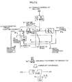
- FIG. 10 is a diagram showing the control system of the single-stand rolling mill S100.
- the single-stand rolling mill S100 has in its entry side an entry tension reel 2 (hereinafter, referred to as 'entry TR2') to feed a material to be rolled to the entry side of the rolling mill 1 so as to make such material inserted into such side and in its exit side an exit tension reel 3 (hereinafter, referred to as 'exit TR3') to wind up the material to be rolled u rolled by the rolling mill 1 with regard to the rolling direction (shown with an arrow in FIG. 10 ) of the rolling mill that is the roll pair.
- 'entry TR2' entry tension reel 2
- 'exit TR3' exit tension reel 3
- the entry TR2 and the exit TR3 are each driven by an electromotor and an entry TR control device 5 and an exit TR control device 6 are provided for such electromotor and the driving control of the electromotor. According to this arrangement, the rolling by the single-stand rolling mill S100 is performed such that after the material to be rolled u unwound from the entry TR2 is rolled with the rolling mill 1, the material to be rolled in the rolled state is wound up by the exit TR3.
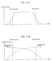
- FIG. 11(A) and FIG. 11(B) are diagrams showing how the reel diameter of the entry TR2 and the exit TR3 respectively changes according as the rolling operation progresses from its initial stage.
- the coil diameter of the entry TR2 is large, the state of which is shown in FIG. 12(A) .
- the coil diameter of the exit TR3 is large, the state of which is shown in FIG. 12(B) .
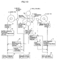
- FIG. 13 is a schematic diagrams showing the speed control device of the rolls and reels of the rolling mill.
- the rolls and reels of the rolling mill are connected to the electromotor through a metallic shaft called a spindle.
- a speed detector is disposed, in which a current instruction is adjusted such that the detected actual speed corresponds to a speed instruction. As the result of it, the current is controlled so that the torque of the electromotor is adjusted, thereby, the speed control being realized.
- the speed control response is lowered.
- the speed control response gets worse than when the reel diameter is small. Therefore, when the rolling mill 1 accelerates and decelerates, it is hard to accelerate and decelerate the reel whose diameter is large in response thereto. In this way, the gist of the present embodiment lies in responding to the reel diameter changing according to the state of the rolling operation.
- a roll gap control device 7 to control the rolled thickness (product thickness) of the material to be rolled u by altering the roll gap which corresponds to the distance between an upper operational roll Rs1 and a lower operational roll Rs2 and a rolling mill speed control device 4 to control the speed (peripheral velocity of the upper and lower operational rolls Rs1 and Rs2) of the rolling mill 1 are provided.
- a speed instruction is outputted from a rolling speed setting device 10 to the rolling mill speed control device 4 and the rolling mill speed control device 4 exerts the control such that the speed (peripheral velocity of the upper and lower operational rolls Rs1 and Rs2) of the rolling mill 1 is made constant.
- the rolling mill speed control device 4 functions as a rotational control unit of a rolling mill.
- the rolling On the entry side of the rolling mill 1 (on the left-hand side of the rolling mill 1 in FIG. 10 ) and the exit side (on the right-hand side thereof in FIG. 10 ), the rolling is stably and efficiently performed with tension applied to the material to be rolled u. It is an entry tension setting device 11 and an exit tension setting device 12 that calculate the tension required for that purpose.
- an entry tension current transformation device 15 and an exit tension current transformation device 16 determine a value of the current to obtain a torque for each electromotor of the entry TR2 and the exit TR3 required for applying the set tensions on the entry side and the exit side to the material to be rolled u based on the entry and exit tension set values calculated by the entry tension setting device 11 and the exit tension setting device 12 and provide the respective values of the current to the entry TR control device 5 and the exit TR control device 6.
- entry TR control device 5 and the exit TR control device 6 they control the current of each electromotor such that it becomes the respectively imparted currents, so that a predetermined tension is applied to the material to be rolled u by the torque of each electromotor provided to the entry TR2 and the exit TR3.
- the entry tension current transformation device 15 and the exit tension current transformation device 16 calculate the set values of the current (set values of the torque of each electromotor) that result in being the set values of the tension based on the models of the TR (tension reel) mechanical system and the TR (tension reel) control device.
- such controlling model entails an error, so that correction is made to the set values of the tension by an entry tension control 13 and an exit tension control 14 with the actual tensions measured by an entry tension meter 8 and an exit tension meter 9 respectively disposed on the entry side and the exit side of the rolling mill 1 and the corrected values are imparted to the entry tension current transformation device 15 and the exit tension current transformation device 16.
- the entry tension current transformation device 15 and the exit tension current transformation device 16 modify the values of the current that are set for the entry TR control device 5 and the exit TR control device 6.
- an exit thickness control device 18 controls the roll gap control device 7 based on the actual thickness detected by an exit thickness meter 17, thereby, the roll gap which is the interval between the rolls of the rolling mill 1 being controlled so as to make the thickness on the exit side (on the right-hand side of the rolling mill 1 in FIG. 1 ) of the rolling mill 1 controlled.
- the exit TR3 and the entry TR2 used for winding up and unwinding the material to be rolled in the single-stand rolling mill are controlled by the constant torque control in which the torque generated by each electromotor is made constant.
- the current instruction for each electromotor is corrected based on the actual tensions detected by the entry tension meter 8 and the exit tension meter 9, thereby the control to make the tension applied to the material to be rolled u constant being exerted.
- the torque of each electromotor of the entry TR2 and the exit TR3 respectively is provided by an electromotor current, so that there are some cases where the constant torque control might be referred to as the constant current control.
- FIG. 14 is a conceptual diagram showing the rolling phenomenon between the entry TR2 of the single-stand rolling mill S100 and the rolling mill 1.
- J denotes the moment of inertia (kg ⁇ m2) of the entry TR2.
- the electromotor torque 22 is a negative value because it is applied reversely to the rotational direction of the entry TR while the tension torque 25 is a positive value because it is applied to the rotational direction thereof.
- M is a mill constant M(kN/m); Q is a plasticity constant Q (kN/m); and ( ⁇ P/ ⁇ Tb)/(M+Q) is an influence coefficient (kb) to the exit thickness associated with the fluctuation of a rolling load P(kN) according to the fluctuation of the entry tension Tb.
- the mass flow constant law is known as the basic formula of rolling control of the rolling mill 1. This is expressed with the following formula (1) based on the fact that the material to be rolled u continues from the entry side of the rolling mill 1 (on the left-hand side of the rolling mill 1 in FIG. 10 ) to the exit side thereof (on the right-hand side thereof in FIG. 10 ).
- H ⁇ V e h ⁇ V o in which H is an entry thickness of the rolling mill 1; h is an exit thickness of the rolling mill 1; V e is an entry speed of the rolling mill 1; and V o is an exit speed of the rolling mill 1.
- the exit thickness fluctuates when the entry speed fluctuates, provided that the entry thickness is constant.
- the entry speed corresponds to the entry TR speed.
- the entry TR2 changes the entry TR speed 20 such that the tension torque 25 corresponds to the electromotor torque 22, but such change is caused by the inertia of the entry TR2, the rolling mill 1 and the rolling phenomenon, so that there is no control means to control the change of the entry TR speed 20.
- the rolling mill entry speed 21 (speed of the material to be rolled u on the entry side of the rolling mill 1) changes so as to generate a deviation ⁇ Tb of the entry tension 24.
- the entry TR speed 20 changes, but by the change, resulting in an exit thickness fluctuation.
- An entry tension suppression system 27 managed by the entry TR2 sometimes entails a large time constant according to the rolling conditions, so that there are some cases where it might cause the fluctuation with large undulation in the exit thickness.
- the entry tension 24 is also suppressed by the rolling phenomenon.
- the rolling load P of the rolling mill 1 fluctuates, along with which the rolling mill entry speed 21 fluctuates.
- the entry tension 24 fluctuates also by such entry tension rolling phenomenon system 28.
- the response of the entry tension rolling phenomenon system 28 is far faster than that of the entry tension suppression system 27, so that the entry rolling phenomenon as shown in FIG. 14 can be converted into that shown in FIG. 15 .
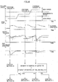
- the relationship among the changed variable of the roll gap 23, the entry tension 24 (Tb), the entry TR speed 20 and the exit thickness is shown in FIG. 16 .
- the entry speed of the rolling mill 1 changes and the entry tension 24 changes.
- the entry TR speed 20 changes by the movement of the entry TR due to its inertia, since the entry TR2 is under the constant torque control.
- the exit thickness control device 18 manipulates the changed variable of the roll gap 23 to make the exit thickness constant. Such series of events continuing, the exit thickness results in vibrating as shown in FIG. 16 .
- exit thickness meter 17 is disposed away from the rolling mill 1, there is a time lag until the exit thickness which is controlled by the exit thickness control device 18 is detected, but when such time lag is sufficiently short against the period of vibration of the exit thickness, it can be ignored.
- a tension speed control means 42 is provided to exert the control such that the tension between the tension reel and the rolling mill is maintained at a value as desired while to prioritize to make the speed of the tension reel constant against deviation from the set value of tension within the predetermined range and to suppress the fluctuation in the speed of the tension reel without correcting the tensional deviation.
- a tension speed control means 42 is provided to exert the control such that the tension between the tension reel and the rolling mill is maintained at a value as desired while to prioritize to make the speed of the tension reel constant against deviation from the set value of tension within the predetermined range and to suppress the fluctuation in the speed of the tension reel without correcting the tensional deviation.
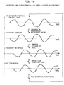
- FIG. 17 is a diagram showing the relationship between such control elements and controlled variables in the case of the single-stand rolling mill.
- the rolling phenomenon of the single-stand rolling mill is as shown in FIG. 18 , the conceptual illustration of which is shown in FIG. 17 .
- control elements comprise the changed variable of the roll gap 23, and the entry TR speed 20 defined as the transferring speed of the material to be rolled.
- controlled variables comprise the rolling mill exit thickness 26 and entry tension 24.
- the changed variable of the roll gap 23 is changed, the change of the exit thickness 26 due to the (roll gap to exit thickness) influence coefficient 503 and the change of the entry tension 24 due to the (roll gap to entry tension) influence coefficient 501 happen.
- the entry TR speed 20 is changed, the change of the entry tension 24 due to the (entry TR speed to entry tension) influence coefficient 502 and the change of the exit thickness 26 due to the (entry TR speed to exit thickness) influence coefficient 504 happen.
- the control in terms of the exit thickness 26 of the rolling mill is exerted by the exit thickness control device 18 changing the roll gap 23. Further, the control in terms of the entry tension 24 is exerted by the entry tension suppression system 27 changing the entry TR speed 20 as shown in FIG. 14 .
- the thickness control device 18 might manipulate the roll gap 23 to control the exit thickness 26, the entry tension 24 largely fluctuates.
- the entry tension suppression system 27 changes the entry TR speed 20, it causes the exit thickness 26 to largely fluctuate.
- the thickness control device 18 manipulates the roll gap 23, with the result that the state where the exit thickness 26, the entry tension 24, the entry TR speed 20 and the roll gap 23 vibrate with the same period occurs.
- the entry rolling phenomenon of the single-stand rolling mill is as shown in FIG. 15 .
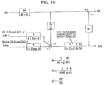
- the similar block diagram to FIG. 17 is shown in FIG. 19 , which is prepared on the basis that the entry tension suppression system 27 by the entry TR2 is removed and the entry TR speed 20 and the changed variable of the roll gap 23 are defined as control elements and the exit thickness 26 and the entry tension 24 are defined as controlled variables.
- the entry tension rolling phenomenon system 28 shown in FIG. 14 is converted into that shown in FIG. 15
- the entry tension rolling phenomenon system 28 is bundled into an entry tension influence coefficient 101.
- the primary delay time constant Tr omitted on the ground that a response time is amply short in comparison with the entry tension suppression system 27 by the entry TR2 is left as it is.
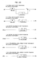
- the influence coefficients 111, 112, 113 and 114 shown in FIG. 20 are obtained.
- V e corresponds to the entry TR speed 20 and h corresponds to the exit thickness 26 of the rolling mill, so that when the exit thickness 26 is small and the entry TR speed 20 is fast, the (entry TR speed to exit thickness) influence coefficient 114 and the (entry TR speed to entry tension) influence coefficient 112 become small. Further, the primary delay time constant Tr included in the entry tension influence coefficient 101 becomes small.
- the (roll gap to exit thickness) influence coefficient 113 becomes small and the response of the (roll gap to entry tension) influence coefficient 111 becomes fast.
- the exit thickness 26 is small and the entry TR speed 20 is fast
- the exit thickness 26 of the rolling mill becomes hard to change while the entry tension becomes easy to change. That is to say, the (roll gap to entry tension) influence coefficient 111 becomes larger than the (roll gap to exit thickness) influence coefficient 113. Further, upon the entry TR speed being manipulated, the entry tension 24 and the exit thickness 26 become hard to change as well.
- the rolling phenomenon term kb also changes according to the rolling speed and the exit thickness, but when the rolling phenomenon term kb becomes large, the (entry TR speed to entry tension) influence coefficient 112 becomes smaller than the (entry TR speed to exit thickness) influence coefficient 114.
- the exit thickness 26 and the entry tension 24 can be stably controlled by adopting a speed thickness control device 50 to control the exit thickness 26 with the entry TR speed 20 and a rolling reduction tension control 51 to control the entry tension 24 with the roll gap 23.
- a speed thickness control device 50 to control the exit thickness 26 with the entry TR speed 20
- a rolling reduction tension control 51 to control the entry tension 24 with the roll gap 23.
- it requires that the entry TR2 conventionally operated under the constant torque control (under the constant current control) be operated under the constant speed control for a change.
- the entry tension suppression system 27 as shown in FIG. 15 turns out to be the primary delay system of the time constant Tq by equivalent conversion.
- the time constant Tq is in proportion to the entry TR speed 20 and in disproportion to the exit thickness 26 of the rolling mill while being in proportion to the rolling phenomenon term kb. Accordingly, when the rolling phenomenon term kb becomes large, the time constant Tq of the entry tension suppression system 27 becomes large, so that the response of the entry tension suppression system 27 is deteriorated. Further, in this case, because the (roll gap to entry tension) influence coefficient 111 as shown in FIG. 17 does not become large, it is considered that the stable control is feasible with the thickness control by the conventional roll gap 23 and the tension control by the entry tension suppression system 27.
- the exit thickness h of the rolling mill 1 can be controlled by changing the entry speed Ve of the rolling mill 1 with the entry TR2 speed, but it is also possible to control the exit thickness h by changing the roll speed Vr of the rolling mill 1.
- b denotes a backward movement ratio of the material to be rolled while f denotes a forward movement ratio thereof.
- the entry tension Tb of the rolling mill 1 is expressed with the following formula (3) while the exit tension Tf thereof is expressed with the following formula (4), in which the speed of the entry TR2 is defined as Vetr while that of the exit TR3 is defined as Vdtr.
- Tb Gb ⁇ ⁇ Vr ⁇ 1 + b ⁇ Vetr dt
- Tf Gf ⁇ ⁇ Vdtr ⁇ Vr ⁇ 1 + f dt
- FIG. 22 is a diagram showing the influence brought by the speed of the rolling mill 1 being changed.
- the speed Vetr of the entry TR2 which corresponds to the entry speed is changed by ⁇ Vetr
- the mass flow constant law turns out to be the following formula (7).
- H ⁇ Vetr + ⁇ Vetr h + ⁇ h ⁇ V 0
- the large coil diameter of the entry TR2 in turn means that the speed responsivity can be further enhanced by manipulating the speed of the exit TR3 than by manipulating the speed of the entry TR2 on the ground that the coil diameter of the exit TR3 is small as shown in FIG. 12(A) so that its moment of inertia is small.
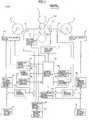
- FIG. 1 The control system of the single-stand rolling mill embodied in the present invention to realize such stable control is shown in FIG. 1 .
- an operation instruction ⁇ S AGC to the roll gap is generated by the rolling reduction thickness control 61 and an operation instruction ⁇ V ETRAGC to the entry TR speed and an operation instruction value ⁇ V MILLAGC to the rolling mill 1 are generated.
- an operation instruction ⁇ V ETRAGC to the entry TR speed and an operation instruction value ⁇ V MILLATR to the rolling mill 1 are generated by the speed tension control 63 and an operation instruction ⁇ S ATR to the roll gap is generated by the rolling reduction tension control 64.
- the addition of a control output from the entry tension control 13 to manipulate the entry tension set value by the deviation between the actual entry tension and the entry tension set value to the entry tension set value by the entry tension setting device 11 is transformed by the entry tension current transformation device 15 as a current instruction to the entry TR2 for the preparation of the current instruction to the entry TR control device 66.
- a control method selection device 70 selectively determines which control methods mentioned above A), B), C), B') and C')should be applied to abate at the maximum the exit thickness fluctuation and the entry tension fluctuation according to the rolling conditions and outputs a roll gap manipulation instruction to the roll gap control device 7 based on the selection result.
- a speed manipulation instruction is outputted to the entry TR speed instruction device 65.
- the entry TR speed instruction is prepared based on an entry TR reference speed outputted from a reference speed setting device 19 and the changed variable of the entry TR speed from the control method selection device 70 so as to be outputted to the entry TR control device 66.
- the control method selection device 70 When the roll speed of the rolling mill 1 is manipulated, the control method selection device 70 outputs a speed manipulation instruction to a rolling mill speed instruction device 81.
- the rolling mill speed instruction device 81 prepares a rolling mill speed instruction based on a rolling mill reference speed outputted from the reference speed setting device 19 and the changed variable of the rolling mill speed from the control method selection device 70 and outputs the rolling mill speed instruction to the rolling mill speed control device 4.
- the entry TR control device 66 there are an operating mode in which the constant torque control (constant current control) according to a current instruction is performed and another operating mode in which the constant speed control according to a speed instruction is performed, which modes are switched over to each other in practical use according to the instruction from the control method selection device 70.
- the entry TR control device 66 functions as a reel rotation control unit.
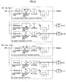
- FIG. 2 shows one example of the block diagram representing the rolling reduction thickness control 61, the speed thickness control 62, the speed tension control 63 and the rolling reduction tension control 64.
- This is just one example of various control systems, so that the other methodical control systems are also applicable.
- the respective control systems are under Integral Control (I Control), but they may be under Proportional Integral Control (PI Control) or Proportional Integral Differential Control (PID Control).
- I Control Integral Control
- PI Control Proportional Integral Control
- PID Control Proportional Integral Differential Control
- a control output ⁇ S AGC is derived from the deviation between an output after the integral and the previous value.
- the speed thickness control 62 is arranged under Integral Control (I Control) in which the exit thickness deviation ⁇ h is rendered into an input and the input exit thickness deviation multiplied by an adjustment gain and a transformation gain from the exit thickness deviation to the entry TR or the mill speed of the rolling mill 1 is integrated.
- a control output expressed with the following formula (15) or (16) is derived from the deviation between an output after the integral and the previous value.
- M denotes a mill constant while Q denotes a plasticity constant of the material to be rolled.
- the speed thickness control instruction is outputted as a speed change ratio against the set speed.
- a control output ⁇ S ATR is derived from the deviation between an output after the integral and the previous value.
- the speed tension control 63 is arranged under Integral Control (I Control) in which the entry tension deviation ⁇ Tb is rendered into an input and the input entry tension deviation ⁇ Tbmultiplied by an adjustment gain and a transformation gain from the entry tension deviation ⁇ Tb to the entry TR or the mill speed of the rolling mill 1 is integrated.
- I Control Integral Control
- a control output expressed with the following formula (17) or (18) is derived from the deviation between an output after the integral and the previous value.
- FIG. 3 shows the synopsis of the control method selection device 70.
- the control method selection device 70 comprises an optimum control method determination device 71 and a control output selection device 72. Which control method among the aforesaid A), B), C), B') and C') is adopted is determined by the optimum control method determination device 71 while which output is adopted among the rolling reduction thickness control 61, the speed thickness control 62, the speed tension control 63 and the rolling reduction tension control 64 is selected by the control output selection device 72, so that a control instruction is outputted to the roll gap control device 7, the entry TR speed instruction device 65, the entry TR control device 66 and the rolling mill speed instruction device 81 respectively.
- the optimum control method determination device 71 functions as a control mode determination unit.
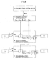
- FIG. 4 shows the operational summary of the optimum control method determination device 71.
- the tension control under rolling reduction and the thickness control under reel speed are performed by means of the control method C) while the thickness control under rolling reduction and the entry tension control to manipulate the TR speed are performed by means of control method B) when a tension modification time constant of the entry tension suppression system 27 is large.
- the control method A) which is conventionally implemented is selected.
- the control method B') or C') to manipulate the rolling mill speed is selectively adopted for the tension control and the thickness control.
- speed is adopted that of the entry TR2 or that of the rolling mill 1
- it may be predetermined that the speed of the rolling mill 1 is manipulated when the moment of inertia of the entry TR 2 including its coil is X times (e.g. twice) as large as the moment of inertia of the speed control system of the rolling mill 1, by way of one example.
- how to set X times it is determined based on the deviational condition of the exit thickness at the actual rolling operation.
- the moment of inertia of the entry TR2 including its coil can be determined based on the reel diameter of the entry TR2 including its coil. Then, the reel diameter of the entry TR2 becomes smaller according as the material to be rolled is unwound while the entry TR2 rotates.
- the reel diameter of the entry TR2 according to the progress of the rolling operation can be calculated based on the number of revolutions of a motor to rotate the entry TR2 and the thickness of the material to be rolled, by way of some examples.
- the control method selection device 70 calculates the reel diameter of the entry TR2 in a real time manner according to the progress of the rolling operation and further calculates the moment of inertia of the entry TR2 including its coil according to the result of such calculation of the reel diameter.
- the moment of inertia of the entry TR2 including its coil calculated in this way is compared with a threshold value defined based on the moment of inertia of the speed control system of the rolling mill 1. As the result of such comparison, when the moment of inertia of the entry TR2 including its coil is larger than the threshold value, the speed of the rolling mill 1 is controlled whereas the speed of the entry TR2 is controlled when it is less than the threshold value.
- the reel diameter of the imaged entry TR2 may be determined by processing the images of the actual entry TR2 captured in a real time.
- the reel diameter as mentioned above that most contributes to the calculation result of the moment of inertia, so that it may be arranged such that a predetermined threshold value is established for the reel diameter and such threshold value is compared with the reel diameter of the entry TR2 on behalf of determining the moment of inertia and comparing such determined moment of inertia with a threshold value.
- the rolling speed is changed in a stepwise manner from a low speed via an intermediate speed to a high speed.
- This stepwise change of the rolling speed is executed to select any one of the aforementioned five control methods.
- the rolling speed is raised in a stepwise manner as shown in FIG. 4 as well.
- the operation shown in FIG. 4 is executable along with the regular rolling operation, which is executable without deteriorating the productivity.
- the changed variable of the entry tension and that of the exit thickness immediately after the roll gap is changed in a stepwise manner are measured and which the (roll gap to entry tension) influence coefficient 114 or the (roll gap to exit thickness) influence coefficient 112 is greater is determined.
- the response time of the entry tension suppression system 27 is determined from the entry tension change when the roll gap is operated in a stepwise manner.
- a low speed zone, an intermediate zone and a high speed zone are defined according to the rolling speed.
- This definition may be such that the rolling speed is divided equally into three parts up to the maximum speed or it is divided according to the other appropriate criteria.
- the roll gap is subjected to a stepwise disturbance. Subjecting the roll gap to such disturbance causes the entry tension and the exit thickness to be fluctuated.
- the parameters dTb, dh and Tbr are determined. Those parameters can be determined through signal processing from the fluctuation conditions of the actual values in the time direction. Based on the largeness relationship among the determined parameters dTb, dh and Tbr and the largeness relationship between the moment of inertia of the entry TR2 and that of the rolling mill 1, any one of the control methods A), B), C), B') and C') is selected.
- any one of the control methods A), B) and C is selected based on the comparison between a value calculated based on the aforementioned parameters dTb, dh and Tbr and a prescribed threshold value. For example, when a value calculated by the fraction of (dh/href)(dTb/Tbref) is a value based on which the control method C) is selected and corresponds to its prescribed threshold value or smaller, according to the comparison between the moment of inertia of the entry TR2 multiplied by a coefficient X and that of the rolling mill 1 multiplied by such coefficient, any one of the control method C) and C') is selected.
- Tbr is a value based on which the control method B) is selected and corresponds to its prescribed threshold value or larger
- any one of the control methods B) and B') is selected according to the comparison between the moment of inertia of the entry TR 2 and that of the rolling mill 1.
- the value based on which the control method C) is selected the value based on which the control method B) is selected and the coefficient X, they may be preliminarily set through the past actual values or the simulation of the rolling mill and as such.
- control method A) is selected as an optimum control method for a low speed
- control method B) or B') is selected as an optimum control method for the intermediate speed
- control method C) or C') is selected as an optimum control method for a high speed.
- the control method selection device 70 executes such optimum control method determination procedures and switches over the control method to the determined optimum control method.
- control method B) or B') and control method C) or C' there are some cases where due to the fact that there is difference in control method of the entry TR among control method A), control method B) or B') and control method C) or C'), they might not be switched over to one another during the rolling operation.
- the rolling operation is continued according to the control method A), and the control method may be switched over to one another when the material to be rolled which is the same type of steel and has the same width as the previous one has arrived.
- the determined optimum control method is stored in the database in which the type of steel for the material to be rolled, the exit thickness and the rolling speed are retrievable, in which when the same type of the material to be rolled is rolled next time, it is controlled according to the optimum control method stored in the database.
- FIG. 6 An example of the stored data in the database is illustrated in FIG. 6 .
- the control method A), control method B) or B') and control method C) or C') might not be switched over to one another during the rolling operation, but the control method B) or B') can be adopted on behalf of the control method A).
- the control method B) or B') can be adopted on behalf of the control method A).
- a stable and high-precision rolling is feasible over the entire speed zones by selecting the control method B) or B') for a low speed while by selecting control method C) or C') in a high speed.
- the aforementioned method is just one example of the optimum control method determination procedures, so that the other methods are also adoptable.
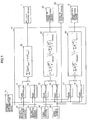
- FIG. 7 shows the operational summary of a control output selection device 72.
- the control output selection device 72 outputs from the rolling reduction thickness control 61, the speed thickness control 62, the speed tension control 63 and the rolling reduction tension control 64 as well as the control method selection result from the optimum control method determination device 71 are rendered into inputs and a control instruction is outputted to the roll gap control device 7, the entry TR speed instruction device 65, the entry TR control device 66 and the rolling mill speed instruction device 81 respectively.
- an output from the rolling reduction thickness control 61, the speed thickness control 62, the speed tension control 63 and the rolling reduction tension control 64 respectively is inputted to the gain controllers 73, 74, 75, 76, 77 and 78.
- Those gain controllers 73 to 78 are signal adjustment units in which the output of the rolling reduction thickness control 61, the speed thickness control 62, the speed tension control 63 and the rolling reduction tension control 64 respectively is outputted with a gain.
- the gains of the gain controllers 73 to 78 are adjusted based on the control method selection result from the optimum control method determination device 71.
- the output from the rolling reduction thickness control 61 is subjected to integral processing so as to be outputted to the roll gap control device 7. Further, the constant torque control mode selection is outputted to the entry TR control device 66.
- the gain of the gain controllers 74 to 78 respectively is set at zero as well as the gain of the gain controller 73 is adjusted, thereby, being set such that the output from the rolling reduction thickness control 61 is subjected to integral processing by means of an integral processing unit 82.
- the constant torque control mode selection is outputted to the entry TR control device 66.
- the entry TR control device 66 functions as a tension reel torque control unit.
- the output from the rolling reduction thickness control 61 is subjected to integral processing so as to be outputted to the roll gap control device 7 as well as the output from the speed tension control 63 is subjected to integral processing so as to be outputted to the entry TR speed instruction device 65 or the rolling mill speed instruction device 81.
- the gain of the gain controllers 74, 75 and 77 respectively is set at zero as well as the gain of the gain controllers 73, 76 and 78 respectively is adjusted, thereby, being set such that the output from the rolling reduction thickness control 61 is subjected to integral processing by means of the integral processing unit 82 as well as the output from the speed tension control 63 is subjected to integral processing by means of the integral processing unit 83 or 84.
- the output from the speed thickness control 62 is subjected to integral processing so as to be outputted to the entry TR speed instruction device 65 or the rolling mill speed instruction device 81 as well as the output from the rolling reduction tension control 64 is subjected to integral processing so as to be outputted to the roll gap control device 7.
- the gain of the gain controllers 73, 76 and 78 respectively is set at zero as well as the gain of the gain controllers 74, 75 and 77 respectively is adjusted, thereby, being set such that the output from the rolling reduction tension control 64 is subjected to integral processing by means of the integral processing unit 82 as well as the output from the speed thickness control 62 is subjected to integral processing by means of the integral processing unit 83 or 84.
- control path in connection with the integral processing unit 82 and the roll gap control device 7 functions as the roll gap control unit. Further, the control path in connection with the integral processing unit 83 and the entry TR speed instruction device 65 or that in connection with the integral processing unit 84 and the rolling mill speed instruction device 81 functions as a speed control unit.
- the control methods A), B), C), B') and C') can be alternatively switched over to one another e.g., according to the rolling speed even during the rolling operation.
- the entry TR speed instruction device 65 as shown in FIG. 8 , with the entry TR speed V ETR prepared at the reference speed setting device 19 with the rolling mill entry backward movement ratio b taken into account based on the rolling mill speed V MILL determined at the rolling speed setting device 10 by the manual operation of an operator, the entry TR speed instruction V ETRref is prepared with a control instruction from the control method selection device 70 so as to be outputted to the entry TR control device 66.
- the rolling mill speed instruction V MILLref is prepared with a control instruction from the control method selection device 70 based on the rolling mill speed V MILL determined at the rolling speed setting device 10 by the manual operation of an operator so as to be outputted to the rolling mill speed control device 4.
- FIG. 9 shows the synopsis of the entry TR control device 66.
- the current to the entry TR2 is outputted with the entry TR speed instruction V ETRref from the entry TR speed instruction device 65, the current instruction I ETRset from the entry tension current transformation device and the constant torque control mode from the control method selection device 70 rendered into inputs.
- the entry TR2 comprises a TR mechanical device and an electromotor to operate such device, in which the current to the entry TR2 denotes that to the electromotor.
- the entry TR control device 66 comprises a P control 661 and an I control 662 to prepare a current instruction such that the speed instruction V ETRref matches the actual speed V ETRfb and a current control 663 to exert the control such that the prepared current instruction I ETRref matches the current I ETRfb flowing through the electromotor of the entry TR2.
- the I control 662 is replaced with an entry TR current set value I ETRset from the entry tension current transformation device 15.
- the P control 661 and the I control 662 are modified according to the entry TR speed deviation.
- control method optimum for the exit thickness control and for the entry thickness control to be selected with the control methods A), B), C), B') and C') switched over to one another according to the rolling conditions, so that the exit thickness precision and the operational efficiency largely improve.
- the rotational speed of the entry TR2 is assumed to be a control element when the speed control is exerted, but when the reel diameter of the entry TR2 is large, its moment of inertia is large while the control response is poor, so that the mill speed of the rolling mill 1 is controlled as well as the rotational speed of the exit TR3 is placed under successive control accordingly.
- This permits the oscillation of the controlled variables caused by controlling the control element whose control response is poor to be prevented.
- the exit thickness is controlled by adjusting the entry TR2 speed and the tension of the material to be rolled is controlled by adjusting the roll gap.
- the adjustment of the entry TR2 speed might affect the tension of the material to be rolled.
- the adjustment of the roll gap might affect the exit thickness.
- non-interference control be exerted.
- the mode of exerting such non-interference control lies in the step of inputting ⁇ S determined by the integral processing unit 82 to the roll gap control device 7 as well as inputting an influence degree to the speed determined based on ⁇ S and the rolling conditions to the integral processing unit 83 e.g., at the control output selection device 72 as shown in FIG. 7 .
- an output signal to the entry TR speed instruction device 65 is calculated with the influence to the thickness or tension caused by the roll gap adjustment taken into account. In other words, it allows the influence to the thickness or tension caused by the roll gap adjustment to be cancelled.
- a module to calculate the influence degree to the speed determined based on the aforementioned ⁇ S and rolling conditions functions as a roll gap adjustment interference prediction unit.
- 1+( ⁇ V/V) determined by the integral processing unit 83 is inputted to the entry TR speed instruction device 65 as well as the influence degree to the thickness or tension determined based on 1+( ⁇ V/V) and the rolling conditions is inputted to the integral processing unit 82.
- an output signal to the roll gap control device 7 is calculated with the influence to the tension caused by the tension reel speed adjustment. In other words, it allows the influence to the thickness or tension caused by the tension reel speed adjustment to be cancelled.
- a module to calculate the influence degree to the tension determined based on the aforesaid 1+( ⁇ V/V) and the rolling conditions functions as an interference prediction unit.
- Such non-interference control is especially effective in the case of concurrently using the control methods A), B), C), B') and C') according to the aforesaid gain control.
- the control methods C) and B) are intermixed, the case where the control method C) is executed by 80% and the control method B) is executed by 20% is presented herein.
- the gain of the gain controller 74 to adjust the output of the rolling reduction tension control 64 is defined as 80% while that of the gain controller 73 to adjust the output of the rolling reduction thickness control 61 is defined as 20%.
- the gain of the gain controller 75 to adjust the output of the speed thickness control 62 is defined as 80% while that of the gain controller 76 to adjust the output of the speed tension control 63 is defined as 20%.
- the rolling conditions are mainly controlled by the influence of the control method C), so that it can be said that the influence to the thickness caused by the roll gap adjustment and the influence to the tension caused by the tension reel speed are minor. Accordingly, in such a case, the control conditions are facilitated by turning off the non-interference control.
- the gain of the gain controller 74 to adjust the output of the rolling reduction tension control 64 is defined as 60% while that of the gain controller 73 to adjust the output of the rolling reduction thickness control 61 is defined as 40%.
- the gain of the gain controller 75 to adjust the output of the speed thickness control 62 is defined as 60% while that of the gain controller 76 to adjust the output of the speed tension control 63 is defined as 40%.
- the rolling conditions are rather controlled by the control method C), but they are more or less controlled by the control method B) as well, so that it can be said that the influence to the thickness caused by the roll gap adjustment and that to the tension caused by the tension reel speed adjustment should be taken into account. Accordingly, in such a case, a favorable control is executable by turning on such non-interference control.
- Such turning-on and off of the non-interference control can be determined based on the ratio of the gain of the gain controller 73 to that of the gain controller 74 and the ratio of the gain of the gain controller 75 to that of the gain controller 76.
- the non-interference control is turned on judging that the control of the gain with such lower value cannot be overlooked.
- the gain with such lower value is a prescribed value or lower
- such non-interference control is turned off judging that the control influenced by the gain with such lower value can be overlooked.
- Such prescribed value is exemplified herein as 20% or 30%.
- the case where the entry tension meter 8 is provided to control the tension is exemplified.
- control methods A), B), C), B') and C') are switched over to one another, but it is also possible to select any one of those control methods beforehand according to the machinery specifications and the product specifications of the materials to be rolled and to continuously use such selected method.
- the database explained with reference to FIG. 6 is adoptable.
- control method for the entry TR2 is described, but the same arrangement as for the entry TR2 is applicable to the control method for the exit TR3.
- the influence to the thickness given by the exit tension is larger according to the types of the rolling mills and the materials to be rolled, there are some cases where it might be more effective to manipulate the exit TR.
- the case where the entry TR2 is operated under the constant speed control while the exit TR3 is operated under the constant torque control is described, but it is also possible to operate the exit TR3 under the constant speed control and to execute the exit tension control with the speed control.
- the speed instruction of the exit TR3 it is possible to execute the entry tension control or the exit thickness control of the rolling mill with the occurrence of the exit tension fluctuation of the rolling mill suppressed to the minimum by considering an extent to which the speed instruction is modified for the rolling mill 1 as the successive extent.
- the tandem rolling mill having a plurality of stands is adoptable just provided that a tension reel is disposed on the entry side or the exit side thereof.
- the tandem rolling mill having a plurality of stands regarded as the single rolling mill, it is possible to execute the same control as described above on the tension between the foremost rolling mill stand and the tension reel and on that between the rearmost rolling mill stand and the tension reel among the plurality of rolling mill stands.
- FIG. 23 is a block diagram showing the hardware configuration of the information processing device constituting the rolling control device embodied herein.
- the rolling control device embodied herein has the same configuration as that of information processing terminals such as a general server, PC (Personal Computer) or the like.
- a CPU Central Processing Unit
- a RAM Random Access Memory
- ROM Read Only Memory
- HDD Hard Disk Drive
- I/F 205 an I/F 205
- an LCD Liquid Crystal Display
- the CPU 201 serves as calculating means for controlling the operations of the rolling control device as a whole.
- the RAM 202 is a volatile storage medium capable of high-speed reading and writing of information, and used as a working area when the CPU 201 processes the information.
- the ROM 203 is a read-only nonvolatile storage medium, in which programs, such as firmware, are stored.
- the HDD 204 is a nonvolatile storage medium capable of reading and writing of information, in which an OS (Operating System), various kinds of control programs, application programs, etc., are stored.
- the I/F 205 connects and controls the bus 208 and various kinds of hardware, networks, etc.
- the I/F 205 is also used as an interface for the respective devices to exchange information or input information to the rolling mill.
- the LCD 206 is a visual user interface for an operator to check the state of the rolling control device.
- the operating unit 207 is a user interface, such as a keyboard or mouse, for an operator to input information into the rolling control device.
- the CPU 201 carries out an operation according to the program stored in the ROM 203 and the HDD 204 or a recording medium such as an optical disk, which is not illustrated, and read by the RAM 202, thereby constituting a software control unit.
- the functions of the rolling control device embodied herein are realized by the combination of the software control unit configured in this manner and the hardware.
- each function is all incorporated in the rolling control device, but such entire functions may be realized in one information processing device or each function may be realized dispersively in a plurality of information processing devices.
- the case where which of the entry TR2 or the rolling mill 1should be decided as a control element for the speed control through the comparison between the resulting moment of inertia of the entry TR2 calculated by some means and the moment of inertia of the rolling mill 1 is exemplified.
- the essence of such decision depends on whether the control response is good or not when a control instruction value is varied. Accordingly, when the entry TR control device 66 varies a control instruction value that it outputs to control the entry TR2, the responsivity may be decided based on the period by which the control result is stabilized according to such varied instruction value.
- the responsivity of the rolling mill 1 does not fluctuate in particular, but the responsivity of the entry TR 2 improves by its reel diameter becoming smaller so as to make its moment inertia smaller according as the rolling operation progresses.
- the rolling mill 1 is initially selected as the control element for the speed control, but such control element is switched over from the rolling mill 1 to the entry TR 2 according as the rolling operation proceeds.
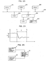
- FIG. 24 is a diagram showing the conception of the responsivity accompanied with the fluctuation of the instruction value of the entry TR2.
- the fluctuation of the instruction value is indicated with a broken line while the state value of the control result is indicated with a solid line.
- the fluctuation of the instruction value is defined as ⁇
- the period by which the state value of the control result is stabilized in pursuit of the instruction value corresponds to a period T from the timing t 1 at which the instruction value has fluctuated to the timing t 2 at which the state value has been stabilized. It is possible to determine whether or not the responsivity is good by checking the ratio of ⁇ to T.
- the entry TR2 is controlled based on the detection result of the entry tension meter 8 as shown in FIG. 1 and the tension set value designated by the entry tension setting device 11, in which there is no 'instruction value' for the rotational speed. Accordingly, there is no value directly corresponding to the broken line as shown in FIG. 24 , so the timing t 1 cannot be determined.
- the factor by which the rotation of the entry TR2 is controlled is when the rotational speed of the rolling mill 1 fluctuates.
- the control speed of the rolling mill 1 fluctuates, it is predicted that the tension of the material to be rolled lying between the entry TR2 and the rolling mill 1 fluctuates, as the result of which the rotational speed of the entry TR2 is controlled.
- the control method selection device 70 acquiring information from the rolling mill speed control device 4 and the entry TR control device 66 respectively, as shown in FIG. 25 .
- the rolling mill speed control device 4 inputs a control value upon controlling the speed of the rolling mill 1 to the control method selection device 70 in a real time manner. This permits the control method selection device 70 to grasp the timing at which the control value against the rolling mill 1 has fluctuated and the resulting fluctuated variable, thereby enabling the timing t 1 and the fluctuated variable as shown in FIG. 24 to be estimated.
- the entry TR control device 66 inputs the state value resulting from the entry TR2 being actually controlled to the control method selection device 70.
- This allows the control method selection device 70 to acquire information indicated with the solid line in FIG. 24 and to calculate the period T by analyzing such information according to the existing method so as to grasp the timing t 2 as shown in FIG. 24 , with the result that the control method selection device 70 can determine the responsivity of the entry TR2 based on the fluctuated variable ⁇ and the period T.
- the control method selection device 70 that determines the responsivity of the entry TR2 in this way discerns whether or not such responsivity is good in a real time manner by comparing the determined result of such responsivity and the prescribed threshold value. Then, when it is determined by the control method selection device 70 that the responsivity of the entry TR2 is better than the prescribed level, the control element for the speed control is switched over from the rolling mill 1 to the entry TR2. That is to say, in FIG. 25 , the control method selection device 70 functions as a control mode determination unit. Such control mode also brings the same advantageous effects as described above.
Description
- The present invention relates to a rolling control device and a rolling control method in details, pertaining to the selection of control elements and feedbacks of a rolling mill having a plurality of control elements and feedbacks.
- In the rolling mill employing a tension reel to unwind and wind materials to be rolled, such reel is operated under the constant torque control (under the constant current control). The problem with which such reel is subjected to the constant torque control lies in that when the tension of the entry and exit sides of the rolling mill fluctuates, the fluctuation in the tension reel speed occurs to suppress such tension fluctuation so as to make the entry side speed of the rolling mill change, with the result that the fluctuation in the exit thickness thereof occurs. To take the corrective measure against such problem, it is implemented that the tension reel is operated under the constant speed control and the tension fluctuation within a certain range is allowed for to suppress the fluctuation in the exit thickness thereof under the tension control in which the tension reel speed is defined as a control element (for example, see
DE 10 2010 013 387 A1 and Japanese Unexamined Patent Application Publication No.2010-240662 - Further, in a tandem rolling mill, it is implemented that a control element for a controlled variable is altered where appropriate when the influence coefficient of the rolling mill changes to a great extent owing to its operational state (for example, see Japanese Unexamined Patent Application Publication No.
2012-176428 2012-176428 - Operating the unwinding tension reel and the winding tension reel under the constant torque control (under the constant current control) causes the fluctuation in the entry speed and exit speed of the rolling mill to bring about the fluctuation in the exit thickness thereof. This is because under such constant torque control the tension reel speed changes due to the inertia of the tension reel to make its torque constant. This results in causing the fluctuation in the exit thickness thereof according to the mass flow constant law.
- The most important issue for the materials to be rolled produced by the rolling mill is the accuracy of the exit thickness of the rolling mill, and the tension at the entry and exit sides thereof is essential just for stabilizing the rolling operation, but there is no problem with the rolling operation even when such tension somewhat might fluctuate for the sole purpose of maintaining the product thickness. Based on such basic understanding, in the prior invention disclosed in Japanese Unexamined Patent Application Publication No.
2010-240662 - In this case, there is no problem just if the tension deviation is within the predetermined range, but according to the rolling conditions or the matrix conditions, there are some cases where it might go beyond such range. If that is the case, the tension reel speed is resultingly altered, so that the entry speed of the rolling mill changes, with the result that the fluctuation in the exit thickness thereof occurs.
- Further, there are some cases where the influence coefficient of the rolling mill changes according to its rolling conditions, so that the tension control in which the tension reel speed is defined as a control element and the exit thickness control in which the roll gap of the rolling mill is defined as a control element become unstable. In such a case, the stable control is hard to be realized just with the exit thickness control in which the existing gap roll is defined as a control element, the tension speed control in which the tension reel is operated under the constant speed control and the constant tension torque control in which the tension reel is operated under the constant torque control, so that the vibration of the exit thickness of the rolling mill occurs.
- In turn, it is proposed (for example, see Japanese Unexamined Patent Application Publication No.
2014-11629 - Even the disclosure of Japanese Unexamined Patent Application Publication No.
2014-11629 - The technical problem to be solved by the present invention is to suppress the vibration of the exit thickness of the rolling mill by exerting in an appropriate manner the control arranged such that tension is generated on the material to be rolled at the entry and exit sides of the rolling mill and the control of the roll gap thereof.
- The present invention adopts the arrangements recited in the scope of the accompanying patent claims, by way of some examples. The present invention encompasses a plurality of the characteristic features to solve the above technical problem, one of which features is characterized in controlling the transferring speed of a material to be rolled inserted in a rolling mill for a rolling operation by the same based on a thickness of the material to be rolled in the rolled state; and controlling one of the rotation of the reel which unwinds and feeds the material to be rolled with regard to the rolling mill and the rotation of the rolling mill so as to control the transferring speed of the material to be rolled.
- According to the present invention, the vibration of the exit thickness of the rolling mill can be suppressed by exerting in an appropriate manner the control arranged such that tension is generated on the material to be rolled at the entry and exit sides of the rolling mill and the control of the roll gap thereof. It should be noted that the technical problems, arrangements and advantageous effects other than those described above are clarified with the following description of embodiments.
- Non-limiting and non-exhaustive embodiments of the present embodiments are described with reference to the following figures, wherein like reference signs refer to like parts throughout the various diagrams unless otherwise specified.
-
FIG. 1 is a diagram showing the entire arrangement of a rolling mill and a rolling control device embodied in the present invention. -
FIG. 2 is a diagram showing the internal functions of a rolling reduction thickness control, a speed thickness control, a speed tension control and a rolling reduction tension control embodied in the present invention. -
FIG. 3 is a diagram showing the internal function of a control method selection device embodied in the present invention. -
FIG. 4 is a diagram showing the operational example of an optimum control method determination device embodied in the present invention. -
FIG. 5 is a diagram showing the operational example of an optimum control method determination device embodied in the present invention. -
FIG. 6 is a diagram showing the database of the control method embodied in the present invention. -
FIG. 7 is a diagram showing the internal function of a control output selection device embodied in the present invention. -
FIG. 8 is a diagram showing the function of an entry TR speed instruction device embodied in the present invention. -
FIG. 9 is a diagram showing the function of an entry TR control device embodied in the present invention. -
FIG. 10 is a diagram showing the entire arrangement of the rolling control device according to the prior art. -
FIG. 11(A) and FIG. 11(B) are diagrams showing the change of the rolling speed and the reel diameter in the rolling operation as the time passes. -
FIG. 12(A) and FIG. 12(B) are diagrams showing the change of the reel diameter. -
FIG. 13 is a diagram showing the manner of controlling the reel speed. -
FIG. 14 is a diagram showing an example of the rolling phenomenon according to the prior art. -
FIG. 15 is a diagram showing an example of an entry tension rolling phenomenon system according to the prior art. -
FIG. 16 is a diagram showing an example of the time-series of each parameter according to the prior art. -
FIG. 17 is a diagram showing the relationship between the control element of the single-stand rolling mill and the controlled variable according to the prior art. -
FIG. 18 is a diagram showing an example of the rolling phenomenon of the single-stand rolling mill according to the prior art. -
FIG. 19 is a diagram exemplarily showing the cross response of the single-stand rolling mill according to the prior art. -
FIG. 20 is a diagram showing a relational example between the control element of the single-stand rolling mill and the controlled variable. -
FIG. 21 is a diagram showing the relationship between the control element and the controlled variable with a cross term taken into account. -
FIG. 22 is a diagram showing the influence caused by the alteration of the rolling mill speed. -
FIG. 23 is a diagram showing the hardware architecture of the rolling control device embodied in the present invention. -
FIG. 24 is a diagram showing the determination concept of the control response embodied in the present invention. -
FIG. 25 is a diagram showing the determination manner of the control response embodied in the present invention. - Hereafter, the present invention is explained in details with a single-stand rolling mill that is a representative rolling mill employing a tension reel to unwind and wind up a material to be rolled exemplified herein.
FIG. 10 is a diagram showing the control system of the single-stand rolling mill S100. The single-stand rolling mill S100 has in its entry side an entry tension reel 2 (hereinafter, referred to as 'entry TR2') to feed a material to be rolled to the entry side of therolling mill 1 so as to make such material inserted into such side and in its exit side an exit tension reel 3 (hereinafter, referred to as 'exit TR3') to wind up the material to be rolled u rolled by the rollingmill 1 with regard to the rolling direction (shown with an arrow inFIG. 10 ) of the rolling mill that is the roll pair. - The entry TR2 and the exit TR3 are each driven by an electromotor and an entry
TR control device 5 and an exitTR control device 6 are provided for such electromotor and the driving control of the electromotor. According to this arrangement, the rolling by the single-stand rolling mill S100 is performed such that after the material to be rolled u unwound from the entry TR2 is rolled with the rollingmill 1, the material to be rolled in the rolled state is wound up by the exit TR3. - Accordingly, the reel diameter of the entry TR2 and the exit TR3 respectively changes according as the rolling operation progresses.
FIG. 11(A) and FIG. 11(B) are diagrams showing how the reel diameter of the entry TR2 and the exit TR3 respectively changes according as the rolling operation progresses from its initial stage. Upon the rolling operation being started, the coil diameter of the entry TR2 is large, the state of which is shown inFIG. 12(A) . At the time when the rolling operation ends, the coil diameter of the exit TR3 is large, the state of which is shown inFIG. 12(B) . -
FIG. 13 is a schematic diagrams showing the speed control device of the rolls and reels of the rolling mill. The rolls and reels of the rolling mill are connected to the electromotor through a metallic shaft called a spindle. At the rear end of the electromotor, a speed detector is disposed, in which a current instruction is adjusted such that the detected actual speed corresponds to a speed instruction. As the result of it, the current is controlled so that the torque of the electromotor is adjusted, thereby, the speed control being realized. - On account that the spindle intervenes for connection between the electromotor and the rolls or the reels, upon the speed control response being enhanced, vibration occurs between the rolls or the reels and the electromotor, so that the stable control becomes hard to be achieved. For instance, the state where the speed response is adjusted such that the control is exerted in an adequate manner in the state where the reel diameter is small as shown in
FIG. 12(B) is considered. In this case, when the reel diameter is enlarged as shown inFIG. 12(A) according to the change of the state of the rolling operation, the speed control system oscillates just with the speed response as it is. - Thus, it requires that the speed control response be lowered. In other words, when the reel diameter is large, the speed control response gets worse than when the reel diameter is small. Therefore, when the rolling
mill 1 accelerates and decelerates, it is hard to accelerate and decelerate the reel whose diameter is large in response thereto. In this way, the gist of the present embodiment lies in responding to the reel diameter changing according to the state of the rolling operation. - In the rolling
mill 1, a rollgap control device 7 to control the rolled thickness (product thickness) of the material to be rolled u by altering the roll gap which corresponds to the distance between an upper operational roll Rs1 and a lower operational roll Rs2 and a rolling millspeed control device 4 to control the speed (peripheral velocity of the upper and lower operational rolls Rs1 and Rs2) of the rollingmill 1 are provided. During the rolling operation, a speed instruction is outputted from a rollingspeed setting device 10 to the rolling millspeed control device 4 and the rolling millspeed control device 4 exerts the control such that the speed (peripheral velocity of the upper and lower operational rolls Rs1 and Rs2) of the rollingmill 1 is made constant. In other words, the rolling millspeed control device 4 functions as a rotational control unit of a rolling mill. - On the entry side of the rolling mill 1 (on the left-hand side of the rolling
mill 1 inFIG. 10 ) and the exit side (on the right-hand side thereof inFIG. 10 ), the rolling is stably and efficiently performed with tension applied to the material to be rolled u. It is an entrytension setting device 11 and an exittension setting device 12 that calculate the tension required for that purpose. Further, an entry tensioncurrent transformation device 15 and an exit tensioncurrent transformation device 16 determine a value of the current to obtain a torque for each electromotor of the entry TR2 and the exit TR3 required for applying the set tensions on the entry side and the exit side to the material to be rolled u based on the entry and exit tension set values calculated by the entrytension setting device 11 and the exittension setting device 12 and provide the respective values of the current to the entryTR control device 5 and the exitTR control device 6. - With the entry
TR control device 5 and the exitTR control device 6, they control the current of each electromotor such that it becomes the respectively imparted currents, so that a predetermined tension is applied to the material to be rolled u by the torque of each electromotor provided to the entry TR2 and the exit TR3. The entry tensioncurrent transformation device 15 and the exit tensioncurrent transformation device 16 calculate the set values of the current (set values of the torque of each electromotor) that result in being the set values of the tension based on the models of the TR (tension reel) mechanical system and the TR (tension reel) control device. - However, such controlling model entails an error, so that correction is made to the set values of the tension by an
entry tension control 13 and anexit tension control 14 with the actual tensions measured by anentry tension meter 8 and anexit tension meter 9 respectively disposed on the entry side and the exit side of the rollingmill 1 and the corrected values are imparted to the entry tensioncurrent transformation device 15 and the exit tensioncurrent transformation device 16. Thereby, the entry tensioncurrent transformation device 15 and the exit tensioncurrent transformation device 16 modify the values of the current that are set for the entryTR control device 5 and the exitTR control device 6. - Further, the thickness of the material to be rolled u is important in light of the product quality, so that the thickness control is exerted. Concretely speaking, an exit
thickness control device 18 controls the rollgap control device 7 based on the actual thickness detected by anexit thickness meter 17, thereby, the roll gap which is the interval between the rolls of the rollingmill 1 being controlled so as to make the thickness on the exit side (on the right-hand side of the rollingmill 1 inFIG. 1 ) of the rollingmill 1 controlled. - The exit TR3 and the entry TR2 used for winding up and unwinding the material to be rolled in the single-stand rolling mill are controlled by the constant torque control in which the torque generated by each electromotor is made constant. Concretely speaking, the current instruction for each electromotor is corrected based on the actual tensions detected by the
entry tension meter 8 and theexit tension meter 9, thereby the control to make the tension applied to the material to be rolled u constant being exerted. It should be noted that the torque of each electromotor of the entry TR2 and the exit TR3 respectively is provided by an electromotor current, so that there are some cases where the constant torque control might be referred to as the constant current control. - When the TR (tension reel) control is exerted under the constant torque control, there is a problem with which it interferes with the thickness control applied to the rolling mill, thereby, the exit thickness precision being deteriorated. The influence against the exit thickness is larger on the entry tension than on the exit tension, so that the problematical points on the entry TR2 in relation to the rolling
mill 1 are explained as follows. -
FIG. 14 is a conceptual diagram showing the rolling phenomenon between the entry TR2 of the single-stand rolling mill S100 and the rollingmill 1. As shown inFIG. 14 , on the entry TR2, the sum of theelectromotor torque 22 that is an output from the entryTR control device 5 and atension torque 25 determined by an entry tension 24 (Tb) and mechanical conditions (reel diameter D and reel gear ratio Gr), in other words, the sum of theelectromotor torque 22 and thetension torque 25 is integrated, thereby, an entry TR (tension reel)speed 20 being determined. It should be noted that J denotes the moment of inertia (kg·m2) of the entry TR2. Here, theelectromotor torque 22 is a negative value because it is applied reversely to the rotational direction of the entry TR while thetension torque 25 is a positive value because it is applied to the rotational direction thereof. - In the rolling
mill 1, anexit thickness 26 is determined based on a value obtained by multiplying a changed variable of the roll gap 23 (=ΔS) by a prescribed coefficient (M/(M+Q)) as shown inFIG. 14 and a value obtained by multiplying theentry tension 24 of the rollingmill 1 by a prescribed coefficient ((∂P/∂Tb)/(M+Q)) as shown inFIG. 14 , based on which determined exit thickness 26 a rollingmill entry speed 21 according to the mass flow constant law is determined. Then, the integrated difference between the rollingmill entry speed 21 and theentry TR speed 20 results in theentry tension 24. InFIG. 11(A) and FIG. 11(B) , it should be noted that M is a mill constant M(kN/m); Q is a plasticity constant Q (kN/m); and (∂P/∂Tb)/(M+Q) is an influence coefficient (kb) to the exit thickness associated with the fluctuation of a rolling load P(kN) according to the fluctuation of the entry tension Tb. - The mass flow constant law is known as the basic formula of rolling control of the rolling
mill 1. This is expressed with the following formula (1) based on the fact that the material to be rolled u continues from the entry side of the rolling mill 1 (on the left-hand side of the rollingmill 1 inFIG. 10 ) to the exit side thereof (on the right-hand side thereof inFIG. 10 ).
mill 1; h is an exit thickness of the rollingmill 1; Ve is an entry speed of the rollingmill 1; and Vo is an exit speed of the rollingmill 1. - From the formula (1) of the mass flow constant law, it is understood that the exit thickness fluctuates when the entry speed fluctuates, provided that the entry thickness is constant. In the case of the single-stand rolling mill (the
single rolling mill 1 shown inFIG. 10 ), the entry speed corresponds to the entry TR speed. The entry TR2 changes theentry TR speed 20 such that thetension torque 25 corresponds to theelectromotor torque 22, but such change is caused by the inertia of the entry TR2, the rollingmill 1 and the rolling phenomenon, so that there is no control means to control the change of theentry TR speed 20. - Thus, in the rolling
mill 1, when the ΔS of the changed variable of theroll gap 23 is manipulated in order to make the exit thickness (thickness of the material to be rolled u on the exit side of the rolling mill 1) constant by the thickness control, the rolling mill entry speed 21 (speed of the material to be rolled u on the entry side of the rolling mill 1) changes so as to generate a deviation ΔTb of theentry tension 24. In order to suppress this, theentry TR speed 20 changes, but by the change, resulting in an exit thickness fluctuation. An entrytension suppression system 27 managed by the entry TR2 sometimes entails a large time constant according to the rolling conditions, so that there are some cases where it might cause the fluctuation with large undulation in the exit thickness. - The
entry tension 24 is also suppressed by the rolling phenomenon. When theentry tension 24 fluctuates, the rolling load P of the rollingmill 1 fluctuates, along with which the rollingmill entry speed 21 fluctuates. Theentry tension 24 fluctuates also by such entry tension rollingphenomenon system 28. The response of the entry tension rollingphenomenon system 28 is far faster than that of the entrytension suppression system 27, so that the entry rolling phenomenon as shown inFIG. 14 can be converted into that shown inFIG. 15 . - It is seen from
FIG. 15 that the changed variable of the roll gap 23 (=ΔS) of the rollingmill 1 comes to the surface in the form of the deviation ΔTb of theentry tension 24 in the same phase, in the state of which deviation being integrated by the entry TR2 theentry TR speed 20 changes. Accordingly, the changed variable of the roll gap 23 (=ΔS), the deviation ΔTb of theentry tension 24, the change in theentry TR speed 20 and the change in the exit thickness are associatively shown inFIG. 13 . The relationship among the changed variable of theroll gap 23, the entry tension 24 (Tb), theentry TR speed 20 and the exit thickness is shown inFIG. 16 . - As shown in
FIG. 16 , as the changed variable of theroll gap 23 changes, the entry speed of the rollingmill 1 changes and theentry tension 24 changes. According as theentry tension 24 changes, theentry TR speed 20 changes by the movement of the entry TR due to its inertia, since the entry TR2 is under the constant torque control. When theentry TR speed 20 changes, the fluctuation in the exit thickness occurs according to the mass flow constant law shown in the above formula (1). When the fluctuation in the exit thickness occurs, the exitthickness control device 18 manipulates the changed variable of theroll gap 23 to make the exit thickness constant. Such series of events continuing, the exit thickness results in vibrating as shown inFIG. 16 . - It should be noted that because the
exit thickness meter 17 is disposed away from the rollingmill 1, there is a time lag until the exit thickness which is controlled by the exitthickness control device 18 is detected, but when such time lag is sufficiently short against the period of vibration of the exit thickness, it can be ignored. - In order to prevent such vibration of the exit thickness, a tension speed control means 42 is provided to exert the control such that the tension between the tension reel and the rolling mill is maintained at a value as desired while to prioritize to make the speed of the tension reel constant against deviation from the set value of tension within the predetermined range and to suppress the fluctuation in the speed of the tension reel without correcting the tensional deviation. However, according to the above method, such a case occurs as the fluctuation in the exit thickness of the rolling mill cannot be suppressed in exchange for suppressing the change in the speed of the tension reel.
- In the rolling mill, there are two control elements, that is, the roll gap and the transferring speed of the material to be rolled and two controlled variables, that is, the exit thickness of the rolling mill and the entry (or exit) tension of the rolling mill. When such two control elements are manipulated, they affect such two controlled variables so that such variables change.
FIG. 17 is a diagram showing the relationship between such control elements and controlled variables in the case of the single-stand rolling mill. The rolling phenomenon of the single-stand rolling mill is as shown inFIG. 18 , the conceptual illustration of which is shown inFIG. 17 . - In the case of the single-
stand rolling mill 1, the control elements comprise the changed variable of theroll gap 23, and theentry TR speed 20 defined as the transferring speed of the material to be rolled. Further, the controlled variables comprise the rollingmill exit thickness 26 andentry tension 24. When the changed variable of theroll gap 23 is changed, the change of theexit thickness 26 due to the (roll gap to exit thickness)influence coefficient 503 and the change of theentry tension 24 due to the (roll gap to entry tension)influence coefficient 501 happen. Moreover, when theentry TR speed 20 is changed, the change of theentry tension 24 due to the (entry TR speed to entry tension)influence coefficient 502 and the change of theexit thickness 26 due to the (entry TR speed to exit thickness)influence coefficient 504 happen. - In the single-
stand rolling mill 1, as shown inFIG. 10 , the control in terms of theexit thickness 26 of the rolling mill is exerted by the exitthickness control device 18 changing theroll gap 23. Further, the control in terms of theentry tension 24 is exerted by the entrytension suppression system 27 changing theentry TR speed 20 as shown inFIG. 14 . - When the (roll gap to exit thickness)
influence coefficient 503 and the (entry TR speed to entry tension)influence coefficient 502 are far larger than the (roll gap to entry tension)influence coefficient 501 and the (entry TR speed to exit thickness)influence coefficient 504, there is no problem with such control system, but as disclosed in Japanese Unexamined Patent Application Publication No.2012-176428 influence coefficient 503 and the (entry TR speed to entry tension)influence coefficient 502 are smaller than the (roll gap to entry tension)influence coefficient 501 and the (entry TR speed to exit thickness)influence coefficient 504, the problem with which the stable control is not exerted happens. - Under such unstable condition, even when the
thickness control device 18 might manipulate theroll gap 23 to control theexit thickness 26, theentry tension 24 largely fluctuates. In order to control such large fluctuation, when the entrytension suppression system 27 changes theentry TR speed 20, it causes theexit thickness 26 to largely fluctuate. When the exit thickness changes, thethickness control device 18 manipulates theroll gap 23, with the result that the state where theexit thickness 26, theentry tension 24, theentry TR speed 20 and theroll gap 23 vibrate with the same period occurs. - The entry rolling phenomenon of the single-stand rolling mill is as shown in
FIG. 15 . The similar block diagram toFIG. 17 is shown inFIG. 19 , which is prepared on the basis that the entrytension suppression system 27 by the entry TR2 is removed and theentry TR speed 20 and the changed variable of theroll gap 23 are defined as control elements and theexit thickness 26 and theentry tension 24 are defined as controlled variables. In the same way as the case where the entry tension rollingphenomenon system 28 shown inFIG. 14 is converted into that shown inFIG. 15 , the entry tension rollingphenomenon system 28 is bundled into an entrytension influence coefficient 101. InFIG. 15 , the primary delay time constant Tr omitted on the ground that a response time is amply short in comparison with the entrytension suppression system 27 by the entry TR2 is left as it is. From the block diagram shown inFIG. 19 , in correspondence to theinfluence coefficients FIG. 17 , theinfluence coefficients FIG. 20 are obtained. - Here, it is seen that Ve corresponds to the
entry TR speed 20 and h corresponds to theexit thickness 26 of the rolling mill, so that when theexit thickness 26 is small and theentry TR speed 20 is fast, the (entry TR speed to exit thickness)influence coefficient 114 and the (entry TR speed to entry tension)influence coefficient 112 become small. Further, the primary delay time constant Tr included in the entrytension influence coefficient 101 becomes small. Thus, the (roll gap to exit thickness)influence coefficient 113 becomes small and the response of the (roll gap to entry tension)influence coefficient 111 becomes fast. In other words, when theexit thickness 26 is small and theentry TR speed 20 is fast, upon theroll gap 23 being manipulated, theexit thickness 26 of the rolling mill becomes hard to change while the entry tension becomes easy to change. That is to say, the (roll gap to entry tension)influence coefficient 111 becomes larger than the (roll gap to exit thickness)influence coefficient 113. Further, upon the entry TR speed being manipulated, theentry tension 24 and theexit thickness 26 become hard to change as well. - As with the entry tension, it includes a rolling phenomenon term kb. The rolling phenomenon term kb also changes according to the rolling speed and the exit thickness, but when the rolling phenomenon term kb becomes large, the (entry TR speed to entry tension)
influence coefficient 112 becomes smaller than the (entry TR speed to exit thickness)influence coefficient 114. - In view of the foregoing, it is seen that there is a case where according as the
exit thickness 26 becomes small and theentry TR speed 20 becomes fast, the (roll gap to exit thickness)influence coefficient 113 becomes smaller than the (roll gap to entry tension)influence coefficient 111 while the (entry TR speed to entry tension)influence coefficient 112 becomes smaller than the (entry TR speed to exit thickness)influence coefficient 114. In such a case, when it is attempted that theexit thickness 26 is controlled with thethickness control device 18 and theentry tension 24 is controlled with the entrytension suppression system 27 as shown inFIG. 11(A) and FIG. 11(B) , the influence of the cross term is so large that the stable control is impossible to be achieved. - In this case, as shown in
FIG. 21 , theexit thickness 26 and theentry tension 24 can be stably controlled by adopting a speedthickness control device 50 to control theexit thickness 26 with theentry TR speed 20 and a rollingreduction tension control 51 to control theentry tension 24 with theroll gap 23. In order to realize such stable control, it requires that the entry TR2 conventionally operated under the constant torque control (under the constant current control) be operated under the constant speed control for a change. - Even when the response of the entry
tension suppression system 27 might be deteriorated, it requires that the entry TR2 be operated under the constant speed control. The entrytension suppression system 27 as shown inFIG. 15 turns out to be the primary delay system of the time constant Tq by equivalent conversion. Here, the time constant Tq is in proportion to theentry TR speed 20 and in disproportion to theexit thickness 26 of the rolling mill while being in proportion to the rolling phenomenon term kb. Accordingly, when the rolling phenomenon term kb becomes large, the time constant Tq of the entrytension suppression system 27 becomes large, so that the response of the entrytension suppression system 27 is deteriorated. Further, in this case, because the (roll gap to entry tension)influence coefficient 111 as shown inFIG. 17 does not become large, it is considered that the stable control is feasible with the thickness control by theconventional roll gap 23 and the tension control by the entrytension suppression system 27. - Here, when the thickness control or the tension control is performed with the entry TR2 operated under the constant speed control and the entry speed changed, the following problem occurs. The moment of inertia of the entry TR2, at the start of the rolling operation, becomes large, since it has a large coil diameter as shown in
FIG. 11(A) and FIG. 11(B) . Thus, the speed response of the entry TR2 is deteriorated further than that of the rollingmill 1. The mass flow constant law as expressed with the above formula (1) is established for the entry speed and thickness of the rolling mill. - The exit thickness h of the rolling
mill 1 can be controlled by changing the entry speed Ve of the rollingmill 1 with the entry TR2 speed, but it is also possible to control the exit thickness h by changing the roll speed Vr of the rollingmill 1. Rewriting the above formula (1) based on the principle right above, the following formula (2) is established. Here, b denotes a backward movement ratio of the material to be rolled while f denotes a forward movement ratio thereof.
- On the other hand, the entry tension Tb of the rolling
mill 1 is expressed with the following formula (3) while the exit tension Tf thereof is expressed with the following formula (4), in which the speed of the entry TR2 is defined as Vetr while that of the exit TR3 is defined as Vdtr.

- Then, to make the entry tension Tb and the exit tension Tf constant, the following formulae (5) and (6) shall be established for Vetr and Vdtr.


- In other words, because the entry tension Tb fluctuates with the speed Vetr of the entry TR2 changed, the mass flow constant law can be established by changing a backward movement ratio b with the roll gap of the rolling
mill 1 changed so as to change the entry speed Ve=Vr·(1+b). -
FIG. 22 is a diagram showing the influence brought by the speed of the rollingmill 1 being changed. When the speed Vetr of the entry TR2 which corresponds to the entry speed is changed by ΔVetr, the mass flow constant law turns out to be the following formula (7).
- As a result of it, the change ratio of the exit thickness is expressed with the following formula (8).

- When the roll speed Vr of the rolling
mill 1 is changed by ΔVr, the following formula (9) is established based on the mass flow constant law.
- Here, when the speed Ve of the entry TR2 is presumed to be unchanged, the following formula (10) is established.

- Then, when the forward movement ratio f is ignored on the assumption that such ratio is minute, the following formula (11) is established based on the formulae (9) and (10).

- Then, based on the above formula (9) and the original formula of the mass flow constant law, the following formula (12) is established, from which formula (12) and the above formula (11) the following formula (13) is derived.


- Then, when the Δh is presumed to be minute, the following formula (14) is established.

- Accordingly, it is possible to change the exit thickness of the rolling
mill 1 as expressed with the above formula (14) by changing the roll speed Vr on the premise that the entry TR2 is made constant. - In view of the fact that the roll speed Vr of the rolling
mill 1 affects the rolling phenomenon thereof as shown inFIG. 19 , an influence is given to the exit thickness h and the entry tension Tb of the rollingmill 1 with an opposite sign to the speed Vetr of the entry TR2. In this case, the (roll speed of rolling mill to exit thickness) influence coefficient is denoted with 1141 and the (roll speed of rolling mill to entry tension) influence coefficient is denoted with 1121 inFIG. 20 . - It is possible to change the exit thickness or entry tension of the rolling
mill 1 by changing the roll speed thereof in the same way as the case where the entry TR speed is changed. In other words, the control exerted by changing the entry TR2 speed is replaceable with the control exerted by changing the roll speed of the rollingmill 1. - Accordingly, when due to the fact that the reel diameter of the entry TR2 is large so that its moment of inertia is large and the speed responsivity is poor, it is possible to increase such speed responsivity by manipulating the roll speed of the rolling
mill 1. In this case, viewed from the requirement that the exit tension of the rollingmill 1 be made constant, it requires that the speed of the exit TR3 be changed according to the changed variable of the speed of the rollingmill 1. - In this case as well, the large coil diameter of the entry TR2 in turn means that the speed responsivity can be further enhanced by manipulating the speed of the exit TR3 than by manipulating the speed of the entry TR2 on the ground that the coil diameter of the exit TR3 is small as shown in
FIG. 12(A) so that its moment of inertia is small. - As described above, even when the reel diameter of the entry TR2 might be large, the problem with which the responsivity becomes poor owing to such largeness of the reel diameter of the entry TR2 is solved by controlling the roll speed of the rolling
mill 1 and the reel speed of the exit TR3 according to the acceleration and/or deceleration of the entry TR. As a result of it, it allows the fluctuation in the exit thickness according to the mass flow constant law to be prevented. - In the rolling equipment, various kinds of materials to be rolled are rolled into various kinds of thicknesses, according to which the rolling speed is varied. Accordingly, there are three cases as follows to permit the exit thickness and entry tension control to be stably exerted according to the rolling conditions. A) Thickness control to manipulate the roll gap and tension control by the entry tension suppression system of the entry TR which is operated under the constant torque control; B)Thickness control to manipulate the roll gap and speed tension control to manipulate the speed of the entry TR which is operated under the constant speed control; C)Rolling reduction tension control to manipulate the roll gap and the speed thickness control to manipulate the speed of the entry TR which is operated under the constant speed control.
- Further, in the cases of the above B) and C) where the speed of the entry TR which is operated under the constant speed control is manipulated, as mentioned above, it is possible to enhance the control response and to improve the thickness precision by manipulating not the entry TR2, but the speed of the rolling
mill 1. That is to say, in the modes of the above B) and C), the following two modified modes are available. In short, those five kinds of control methods are available in exchange with one another in practical use. Namely, B')thickness control to manipulate the roll gap and speed tension control to manipulate the speed of the rolling mill which is operated under the constant speed control; and C') rolling reduction tension control to manipulate the roll gap and speed thickness control to manipulate the speed of the rolling mill that is operated under the constant speed control. - In order to stably exert the thickness control and tension control of the rolling mill, in practical use, it requires that the above three kinds of control modes be switched over to one another according to the rolling conditions. The control system of the single-stand rolling mill embodied in the present invention to realize such stable control is shown in
FIG. 1 . With the exit thickness deviation Δh detected by theexit thickness meter 17, an operation instruction ΔΔSAGC to the roll gap is generated by the rollingreduction thickness control 61 and an operation instruction ΔΔVETRAGC to the entry TR speed and an operation instruction value ΔΔVMILLAGC to the rollingmill 1 are generated. Further, with the deviation (entry tension deviation) ΔTb between the actual entry tension measured by theentry tension meter 8 and the entry tension set by the entrytension setting device 11, an operation instruction ΔΔVETRAGC to the entry TR speed and an operation instruction value ΔΔVMILLATR to the rollingmill 1 are generated by thespeed tension control 63 and an operation instruction ΔΔSATR to the roll gap is generated by the rollingreduction tension control 64. - Further, in the case where the entry TR2 is operated under the constant torque control, the addition of a control output from the
entry tension control 13 to manipulate the entry tension set value by the deviation between the actual entry tension and the entry tension set value to the entry tension set value by the entrytension setting device 11 is transformed by the entry tensioncurrent transformation device 15 as a current instruction to the entry TR2 for the preparation of the current instruction to the entryTR control device 66. - A control
method selection device 70 selectively determines which control methods mentioned above A), B), C), B') and C')should be applied to abate at the maximum the exit thickness fluctuation and the entry tension fluctuation according to the rolling conditions and outputs a roll gap manipulation instruction to the rollgap control device 7 based on the selection result. When the entry TR speed is manipulated, a speed manipulation instruction is outputted to the entry TRspeed instruction device 65. At the entry TRspeed instruction device 65, the entry TR speed instruction is prepared based on an entry TR reference speed outputted from a referencespeed setting device 19 and the changed variable of the entry TR speed from the controlmethod selection device 70 so as to be outputted to the entryTR control device 66. - When the roll speed of the rolling
mill 1 is manipulated, the controlmethod selection device 70 outputs a speed manipulation instruction to a rolling millspeed instruction device 81. The rolling millspeed instruction device 81 prepares a rolling mill speed instruction based on a rolling mill reference speed outputted from the referencespeed setting device 19 and the changed variable of the rolling mill speed from the controlmethod selection device 70 and outputs the rolling mill speed instruction to the rolling millspeed control device 4. - At the entry
TR control device 66, there are an operating mode in which the constant torque control (constant current control) according to a current instruction is performed and another operating mode in which the constant speed control according to a speed instruction is performed, which modes are switched over to each other in practical use according to the instruction from the controlmethod selection device 70. In other words, the entryTR control device 66 functions as a reel rotation control unit. -
FIG. 2 shows one example of the block diagram representing the rollingreduction thickness control 61, thespeed thickness control 62, thespeed tension control 63 and the rollingreduction tension control 64. This is just one example of various control systems, so that the other methodical control systems are also applicable. For instance, in the example as shown inFIG. 2 , the respective control systems are under Integral Control (I Control), but they may be under Proportional Integral Control (PI Control) or Proportional Integral Differential Control (PID Control). - The rolling
reduction thickness control 61 is arranged under Integral Control (I Control) in which the exit thickness deviation Δh = hfb-href that is the difference between an actual exit thickness hfb and an exit thickness set value href is rendered into an input and the input exit thickness deviation multiplied by an adjustment gain and a transformation gain from the exit thickness deviation to the roll gap is integrated. A control output ΔΔSAGC is derived from the deviation between an output after the integral and the previous value. Further, thespeed thickness control 62 is arranged under Integral Control (I Control) in which the exit thickness deviation Δh is rendered into an input and the input exit thickness deviation multiplied by an adjustment gain and a transformation gain from the exit thickness deviation to the entry TR or the mill speed of the rollingmill 1 is integrated. A control output expressed with the following formula (15) or (16) is derived from the deviation between an output after the integral and the previous value.

- Here, M denotes a mill constant while Q denotes a plasticity constant of the material to be rolled. Further, the speed thickness control instruction is outputted as a speed change ratio against the set speed.
- The rolling
reduction tension control 64 is arranged under Integral Control (I Control) in which an entry tension deviation ΔTb=Tbfbb-Tbref that is the difference between an actual entry tension Tbfbb and an entry tension setvalue Tbref is rendered into an input and the input entry tension deviation ΔTb multiplied by an adjustment gain and a transformation gain from the entry tension deviation ΔTb to the roll gap is integrated. A control output ΔΔSATR is derived from the deviation between an output after the integral and the previous value. - Moreover, the
speed tension control 63 is arranged under Integral Control (I Control) in which the entry tension deviation ΔTb is rendered into an input and the input entry tension deviation ΔTbmultiplied by an adjustment gain and a transformation gain from the entry tension deviation ΔTb to the entry TR or the mill speed of the rollingmill 1 is integrated. A control output expressed with the following formula (17) or (18) is derived from the deviation between an output after the integral and the previous value.

-
FIG. 3 shows the synopsis of the controlmethod selection device 70. The controlmethod selection device 70 comprises an optimum controlmethod determination device 71 and a controloutput selection device 72. Which control method among the aforesaid A), B), C), B') and C') is adopted is determined by the optimum controlmethod determination device 71 while which output is adopted among the rollingreduction thickness control 61, thespeed thickness control 62, thespeed tension control 63 and the rollingreduction tension control 64 is selected by the controloutput selection device 72, so that a control instruction is outputted to the rollgap control device 7, the entry TRspeed instruction device 65, the entryTR control device 66 and the rolling millspeed instruction device 81 respectively. In other words, the optimum controlmethod determination device 71 functions as a control mode determination unit. -
FIG. 4 shows the operational summary of the optimum controlmethod determination device 71. Herein, when the (roll gap to entry tension)influence coefficient 111 is large, the tension control under rolling reduction and the thickness control under reel speed are performed by means of the control method C) while the thickness control under rolling reduction and the entry tension control to manipulate the TR speed are performed by means of control method B) when a tension modification time constant of the entrytension suppression system 27 is large. Otherwise, the control method A) which is conventionally implemented is selected. - Further, when the reel diameter of the entry TR2 is large and its speed control response is poorer than that of the rolling
mill 1, the control method B') or C') to manipulate the rolling mill speed is selectively adopted for the tension control and the thickness control. Here, as to which speed is adopted that of the entry TR2 or that of the rollingmill 1, it may be predetermined that the speed of the rollingmill 1 is manipulated when the moment of inertia of theentry TR 2 including its coil is X times (e.g. twice) as large as the moment of inertia of the speed control system of the rollingmill 1, by way of one example. As for how to set X times, it is determined based on the deviational condition of the exit thickness at the actual rolling operation. - The moment of inertia of the entry TR2 including its coil can be determined based on the reel diameter of the entry TR2 including its coil. Then, the reel diameter of the entry TR2 becomes smaller according as the material to be rolled is unwound while the entry TR2 rotates. The reel diameter of the entry TR2 according to the progress of the rolling operation can be calculated based on the number of revolutions of a motor to rotate the entry TR2 and the thickness of the material to be rolled, by way of some examples.
- On the contrary, the moment of inertia of the speed control system of the rolling
mill 1 is unchanged. Accordingly, the controlmethod selection device 70 calculates the reel diameter of the entry TR2 in a real time manner according to the progress of the rolling operation and further calculates the moment of inertia of the entry TR2 including its coil according to the result of such calculation of the reel diameter. The moment of inertia of the entry TR2 including its coil calculated in this way is compared with a threshold value defined based on the moment of inertia of the speed control system of the rollingmill 1. As the result of such comparison, when the moment of inertia of the entry TR2 including its coil is larger than the threshold value, the speed of the rollingmill 1 is controlled whereas the speed of the entry TR2 is controlled when it is less than the threshold value. - It should be noted that as the method to determine the reel diameter of the entry TR2, besides the manner by which it is determined based on the number of revolutions of the motor and the thickness of the material to be rolled as mentioned above, the reel diameter of the imaged entry TR2 may be determined by processing the images of the actual entry TR2 captured in a real time.
- Further, it is the reel diameter as mentioned above that most contributes to the calculation result of the moment of inertia, so that it may be arranged such that a predetermined threshold value is established for the reel diameter and such threshold value is compared with the reel diameter of the entry TR2 on behalf of determining the moment of inertia and comparing such determined moment of inertia with a threshold value.
- Which is selected among the above five control methods is determined as follows. It is deemed that the optimum control method changes according to the type of steel adopted for the material to be rolled, the exit thickness and the rolling speed, so that the rolling speed is substantially divided into the three stages, that is, a low speed, an intermediate speed and a high speed when the type of steel and the exit thickness change and the change in the entry tension and the exit thickness is checked with the roll gap changed in a stepwise manner. In this case, when the changed variable of the roll gap is changed to the extent by which it does not affect the product quality of the material to be rolled, the roll gap change is executable even during the rolling operation of the product material. In this regard, when the roll gap is changed in a stepwise manner, it is seen to it the aforementioned control method A) is selected.
- It should be noted that in this embodiment, as shown in
FIG. 4 , the rolling speed is changed in a stepwise manner from a low speed via an intermediate speed to a high speed. This stepwise change of the rolling speed is executed to select any one of the aforementioned five control methods. However, when the actual rolling operation starts, the rolling speed is raised in a stepwise manner as shown inFIG. 4 as well. Thus, the operation shown inFIG. 4 is executable along with the regular rolling operation, which is executable without deteriorating the productivity. - The changed variable of the entry tension and that of the exit thickness immediately after the roll gap is changed in a stepwise manner are measured and which the (roll gap to entry tension)
influence coefficient 114 or the (roll gap to exit thickness)influence coefficient 112 is greater is determined. In this regard, the response time of the entrytension suppression system 27 is determined from the entry tension change when the roll gap is operated in a stepwise manner. - For instance, as shown in
FIG. 4 , a low speed zone, an intermediate zone and a high speed zone are defined according to the rolling speed. This definition may be such that the rolling speed is divided equally into three parts up to the maximum speed or it is divided according to the other appropriate criteria. When the rolling speed corresponds to such zones, the roll gap is subjected to a stepwise disturbance. Subjecting the roll gap to such disturbance causes the entry tension and the exit thickness to be fluctuated. - Then, as shown in
FIG. 5 , based on the actual entry tension and exit thickness deviation, the parameters dTb, dh and Tbr are determined. Those parameters can be determined through signal processing from the fluctuation conditions of the actual values in the time direction. Based on the largeness relationship among the determined parameters dTb, dh and Tbr and the largeness relationship between the moment of inertia of the entry TR2 and that of the rollingmill 1, any one of the control methods A), B), C), B') and C') is selected. - Upon selecting any one of the control methods A), B) and C), as shown in
FIG. 5 , it is determined based on the comparison between a value calculated based on the aforementioned parameters dTb, dh and Tbr and a prescribed threshold value. For example, when a value calculated by the fraction of (dh/href)(dTb/Tbref) is a value based on which the control method C) is selected and corresponds to its prescribed threshold value or smaller, according to the comparison between the moment of inertia of the entry TR2 multiplied by a coefficient X and that of the rollingmill 1 multiplied by such coefficient, any one of the control method C) and C') is selected. - Further, when Tbr is a value based on which the control method B) is selected and corresponds to its prescribed threshold value or larger, any one of the control methods B) and B') is selected according to the comparison between the moment of inertia of the
entry TR 2 and that of the rollingmill 1. As for the value based on which the control method C) is selected, the value based on which the control method B) is selected and the coefficient X, they may be preliminarily set through the past actual values or the simulation of the rolling mill and as such. - Upon performing such optimum control method selection processing on the
stepwise changes FIG. 4 , it results in that the control method A) is selected as an optimum control method for a low speed; the control method B) or B') is selected as an optimum control method for the intermediate speed; and the control method C) or C') is selected as an optimum control method for a high speed. - The control
method selection device 70 executes such optimum control method determination procedures and switches over the control method to the determined optimum control method. In this case, there are some cases where due to the fact that there is difference in control method of the entry TR among control method A), control method B) or B') and control method C) or C'), they might not be switched over to one another during the rolling operation. In such a case, the rolling operation is continued according to the control method A), and the control method may be switched over to one another when the material to be rolled which is the same type of steel and has the same width as the previous one has arrived. The determined optimum control method is stored in the database in which the type of steel for the material to be rolled, the exit thickness and the rolling speed are retrievable, in which when the same type of the material to be rolled is rolled next time, it is controlled according to the optimum control method stored in the database. - An example of the stored data in the database is illustrated in
FIG. 6 . According to the type of the rolling equipment, there are some cases where the control method A), control method B) or B') and control method C) or C') might not be switched over to one another during the rolling operation, but the control method B) or B') can be adopted on behalf of the control method A). In this way, in the case of the material to be rolled for which the control method A) is adopted in a low speed while the control method C) or C') is optimum for a high speed, a stable and high-precision rolling is feasible over the entire speed zones by selecting the control method B) or B') for a low speed while by selecting control method C) or C') in a high speed. - To note, the aforementioned method is just one example of the optimum control method determination procedures, so that the other methods are also adoptable. By way of one example, it is also possible to select an optimum control method by numerically determining influence coefficients as shown in
FIG. 20 with the rolling phenomenon model from the rolling actualities and based on their largeness relationship. -
FIG. 7 shows the operational summary of a controloutput selection device 72. At the controloutput selection device 72, outputs from the rollingreduction thickness control 61, thespeed thickness control 62, thespeed tension control 63 and the rollingreduction tension control 64 as well as the control method selection result from the optimum controlmethod determination device 71 are rendered into inputs and a control instruction is outputted to the rollgap control device 7, the entry TRspeed instruction device 65, the entryTR control device 66 and the rolling millspeed instruction device 81 respectively. - As shown in
FIG. 7 , at the controloutput selection device 72, an output from the rollingreduction thickness control 61, thespeed thickness control 62, thespeed tension control 63 and the rollingreduction tension control 64 respectively is inputted to thegain controllers gain controllers 73 to 78 are signal adjustment units in which the output of the rollingreduction thickness control 61, thespeed thickness control 62, thespeed tension control 63 and the rollingreduction tension control 64 respectively is outputted with a gain. The gains of thegain controllers 73 to 78 are adjusted based on the control method selection result from the optimum controlmethod determination device 71. - In the case of selecting the control method A), the output from the rolling
reduction thickness control 61 is subjected to integral processing so as to be outputted to the rollgap control device 7. Further, the constant torque control mode selection is outputted to the entryTR control device 66. For that purpose, according to the control method selection result by the optimum controlmethod determination device 71, the gain of thegain controllers 74 to 78 respectively is set at zero as well as the gain of thegain controller 73 is adjusted, thereby, being set such that the output from the rollingreduction thickness control 61 is subjected to integral processing by means of anintegral processing unit 82. Further, according to the control method selection result by the optimum controlmethod determination device 71, the constant torque control mode selection is outputted to the entryTR control device 66. In this case, the entryTR control device 66 functions as a tension reel torque control unit. - In the case of selecting the control method B), the output from the rolling
reduction thickness control 61 is subjected to integral processing so as to be outputted to the rollgap control device 7 as well as the output from thespeed tension control 63 is subjected to integral processing so as to be outputted to the entry TRspeed instruction device 65 or the rolling millspeed instruction device 81. For that purpose, according to the control method selection result by the optimum controlmethod determination device 71, the gain of thegain controllers gain controllers reduction thickness control 61 is subjected to integral processing by means of theintegral processing unit 82 as well as the output from thespeed tension control 63 is subjected to integral processing by means of theintegral processing unit - In the case of selecting the control method C), the output from the
speed thickness control 62 is subjected to integral processing so as to be outputted to the entry TRspeed instruction device 65 or the rolling millspeed instruction device 81 as well as the output from the rollingreduction tension control 64 is subjected to integral processing so as to be outputted to the rollgap control device 7. For that purpose, according to the control method selection result by the optimum controlmethod determination device 71, the gain of thegain controllers gain controllers reduction tension control 64 is subjected to integral processing by means of theintegral processing unit 82 as well as the output from thespeed thickness control 62 is subjected to integral processing by means of theintegral processing unit - In other words, the control path in connection with the
integral processing unit 82 and the rollgap control device 7 functions as the roll gap control unit. Further, the control path in connection with theintegral processing unit 83 and the entry TRspeed instruction device 65 or that in connection with theintegral processing unit 84 and the rolling millspeed instruction device 81 functions as a speed control unit. - By adopting the method as shown in
FIG. 7 , the control methods A), B), C), B') and C') can be alternatively switched over to one another e.g., according to the rolling speed even during the rolling operation. At the entry TRspeed instruction device 65, as shown inFIG. 8 , with the entry TR speed VETR prepared at the referencespeed setting device 19 with the rolling mill entry backward movement ratio b taken into account based on the rolling mill speed VMILL determined at the rollingspeed setting device 10 by the manual operation of an operator, the entry TR speed instruction VETRref is prepared with a control instruction from the controlmethod selection device 70 so as to be outputted to the entryTR control device 66. - Further, at the rolling mill
speed instruction device 81, as shown inFIG. 21 , the rolling mill speed instruction VMILLref is prepared with a control instruction from the controlmethod selection device 70 based on the rolling mill speed VMILL determined at the rollingspeed setting device 10 by the manual operation of an operator so as to be outputted to the rolling millspeed control device 4. -
FIG. 9 shows the synopsis of the entryTR control device 66. The current to the entry TR2 is outputted with the entry TR speed instruction VETRref from the entry TRspeed instruction device 65, the current instruction IETRset from the entry tension current transformation device and the constant torque control mode from the controlmethod selection device 70 rendered into inputs. Here, the entry TR2 comprises a TR mechanical device and an electromotor to operate such device, in which the current to the entry TR2 denotes that to the electromotor. - The entry
TR control device 66 comprises aP control 661 and an I control 662 to prepare a current instruction such that the speed instruction VETRref matches the actual speed VETRfb and acurrent control 663 to exert the control such that the prepared current instruction IETRref matches the current IETRfb flowing through the electromotor of the entry TR2. When the constant torque control mode is selected, theI control 662 is replaced with an entry TR current set value IETRset from the entry tensioncurrent transformation device 15. When the constant torque control mode is not selected (constant speed control), theP control 661 and theI control 662 are modified according to the entry TR speed deviation. - In this state, when the constant torque control mode is selected, correction is made by means of a
current correction 664 such that the entry TR current instruction IETRref does not discontinuously change. Such arrangement permits the control mode of the entry TR control device to be freely switched over from the constant torque control to the constant speed control or vice versa even during the rolling operation, which enables the control methods A), B) and C) to be freely switched over to one another. - The foregoing control arrangement allows the control method optimum for the exit thickness control and for the entry thickness control to be selected with the control methods A), B), C), B') and C') switched over to one another according to the rolling conditions, so that the exit thickness precision and the operational efficiency largely improve.
- Especially, according to the rolling control embodied herein, the rotational speed of the entry TR2 is assumed to be a control element when the speed control is exerted, but when the reel diameter of the entry TR2 is large, its moment of inertia is large while the control response is poor, so that the mill speed of the rolling
mill 1 is controlled as well as the rotational speed of the exit TR3 is placed under successive control accordingly. This permits the oscillation of the controlled variables caused by controlling the control element whose control response is poor to be prevented. - It should be noted that in the above embodiment the case where the gains for the unused outputs according to the control methods are set at zero among the outputs of the rolling
reduction thickness control 61, thespeed thickness control 62, thespeed tension control 63 and the rollingreduction tension control 64 is exemplified as shown inFIG. 7 . Besides, with the respective gains not set at zero, but reduced, it is also possible to concurrently use the control methods A), B), C), B') and C') with the outputs of the rollingreduction thickness control 61, thespeed thickness control 62, thespeed tension control 63 and the rollingreduction tension control 64 mixed with one another in proportion to such reduced gains. - Further, in the above embodiment, e.g., in the case of the control method C), the exit thickness is controlled by adjusting the entry TR2 speed and the tension of the material to be rolled is controlled by adjusting the roll gap. However, according to the rolling conditions, there is possibility that the adjustment of the entry TR2 speed might affect the tension of the material to be rolled. Further, there is likelihood that the adjustment of the roll gap might affect the exit thickness.
- In order to avoid such unexpected influence, it is preferred that non-interference control be exerted. The mode of exerting such non-interference control lies in the step of inputting ΔS determined by the
integral processing unit 82 to the rollgap control device 7 as well as inputting an influence degree to the speed determined based on ΔS and the rolling conditions to theintegral processing unit 83 e.g., at the controloutput selection device 72 as shown inFIG. 7 . In this way, at theintegral processing unit 83, an output signal to the entry TRspeed instruction device 65 is calculated with the influence to the thickness or tension caused by the roll gap adjustment taken into account. In other words, it allows the influence to the thickness or tension caused by the roll gap adjustment to be cancelled. In such non-interference control, a module to calculate the influence degree to the speed determined based on the aforementioned ΔS and rolling conditions functions as a roll gap adjustment interference prediction unit. - Moreover, at the control
output selection device 72 as shown inFIG. 7 , 1+(ΔV/V) determined by theintegral processing unit 83 is inputted to the entry TRspeed instruction device 65 as well as the influence degree to the thickness or tension determined based on 1+(ΔV/V) and the rolling conditions is inputted to theintegral processing unit 82. In this way, at theintegral processing unit 82, an output signal to the rollgap control device 7 is calculated with the influence to the tension caused by the tension reel speed adjustment. In other words, it allows the influence to the thickness or tension caused by the tension reel speed adjustment to be cancelled. In such non-interference control, a module to calculate the influence degree to the tension determined based on the aforesaid 1+(ΔV/V) and the rolling conditions functions as an interference prediction unit. - Such non-interference control is especially effective in the case of concurrently using the control methods A), B), C), B') and C') according to the aforesaid gain control. For example, when the control methods C) and B) are intermixed, the case where the control method C) is executed by 80% and the control method B) is executed by 20% is presented herein.
- In this case, the gain of the
gain controller 74 to adjust the output of the rollingreduction tension control 64 is defined as 80% while that of thegain controller 73 to adjust the output of the rollingreduction thickness control 61 is defined as 20%. Likewise, the gain of thegain controller 75 to adjust the output of thespeed thickness control 62 is defined as 80% while that of thegain controller 76 to adjust the output of thespeed tension control 63 is defined as 20%. - In this case, it is appropriate to say that the rolling conditions are mainly controlled by the influence of the control method C), so that it can be said that the influence to the thickness caused by the roll gap adjustment and the influence to the tension caused by the tension reel speed are minor. Accordingly, in such a case, the control conditions are facilitated by turning off the non-interference control.
- On the other hand, when the control methods C) and B) are intermixed, the case where the control method C) is executed by 60% while the control method B) is executed by 40% is presented herein. In this case, the gain of the
gain controller 74 to adjust the output of the rollingreduction tension control 64 is defined as 60% while that of thegain controller 73 to adjust the output of the rollingreduction thickness control 61 is defined as 40%. Likewise, the gain of thegain controller 75 to adjust the output of thespeed thickness control 62 is defined as 60% while that of thegain controller 76 to adjust the output of thespeed tension control 63 is defined as 40%. - In this case, it is appropriate to say that the rolling conditions are rather controlled by the control method C), but they are more or less controlled by the control method B) as well, so that it can be said that the influence to the thickness caused by the roll gap adjustment and that to the tension caused by the tension reel speed adjustment should be taken into account. Accordingly, in such a case, a favorable control is executable by turning on such non-interference control.
- Such turning-on and off of the non-interference control can be determined based on the ratio of the gain of the
gain controller 73 to that of thegain controller 74 and the ratio of the gain of thegain controller 75 to that of thegain controller 76. By way of one example, between values of two gains which correspond to each other in such a manner that they become 100% by addition, when the gain with a lower value goes beyond a prescribed value, the non-interference control is turned on judging that the control of the gain with such lower value cannot be overlooked. In turn, when the gain with such lower value is a prescribed value or lower, such non-interference control is turned off judging that the control influenced by the gain with such lower value can be overlooked. Such prescribed value is exemplified herein as 20% or 30%. - Then, in the above embodiment, the case where the
entry tension meter 8 is provided to control the tension is exemplified. Alternatively, it is also possible to estimate the tension based on the difference between the actual value of the output current by the entryTR control device 66 and the current instruction value outputted by the entry tensioncurrent transformation device 15. For instance, when the actual value is higher than the instruction value, the entryTR control device 66 is in the state where it tries to lower the tension of the material to be rolled, so that it can be estimated that the tension at that state is higher than the tension set by the entrytension setting device 11. - Further, in the above embodiment, as explained with reference to
FIG. 4 andFIG. 5 , according to the actual rolling conditions, the control methods A), B), C), B') and C') are switched over to one another, but it is also possible to select any one of those control methods beforehand according to the machinery specifications and the product specifications of the materials to be rolled and to continuously use such selected method. In such a case, the database explained with reference toFIG. 6 is adoptable. - Then, in the above embodiment, the control method for the entry TR2 is described, but the same arrangement as for the entry TR2 is applicable to the control method for the exit TR3. When the influence to the thickness given by the exit tension is larger according to the types of the rolling mills and the materials to be rolled, there are some cases where it might be more effective to manipulate the exit TR.
- Then, in the above embodiment, the case where the entry TR2 is operated under the constant speed control while the exit TR3 is operated under the constant torque control is described, but it is also possible to operate the exit TR3 under the constant speed control and to execute the exit tension control with the speed control. In this case, as for the speed instruction of the exit TR3, it is possible to execute the entry tension control or the exit thickness control of the rolling mill with the occurrence of the exit tension fluctuation of the rolling mill suppressed to the minimum by considering an extent to which the speed instruction is modified for the rolling
mill 1 as the successive extent. - Further, in the above embodiment, the case where the single-stand rolling mill is exemplified is described, but not only such single-stand rolling mill, but also the tandem rolling mill having a plurality of stands is adoptable just provided that a tension reel is disposed on the entry side or the exit side thereof. In other words, with the tandem rolling mill having a plurality of stands regarded as the single rolling mill, it is possible to execute the same control as described above on the tension between the foremost rolling mill stand and the tension reel and on that between the rearmost rolling mill stand and the tension reel among the plurality of rolling mill stands.
- Furthermore, the rolling control device centered on the control
method selection device 70 explained with reference toFIG. 1 is realized by the combination of software and hardware. Here, the hardware for implementing each function of the rolling control device embodied herein will be described with reference toFIG. 23. FIG. 23 is a block diagram showing the hardware configuration of the information processing device constituting the rolling control device embodied herein. As shown inFIG. 23 , the rolling control device embodied herein has the same configuration as that of information processing terminals such as a general server, PC (Personal Computer) or the like. - That is, in the rolling control device according to this embodiment, a CPU (Central Processing Unit) 201, a RAM (Random Access Memory) 202, a ROM (Read Only Memory) 203, an HDD (Hard Disk Drive) 204, and an I/
F 205 are connected via abus 208. Furthermore, an LCD (Liquid Crystal Display) 206 and anoperating unit 207 are connected to the I/F 205. - The
CPU 201 serves as calculating means for controlling the operations of the rolling control device as a whole. TheRAM 202 is a volatile storage medium capable of high-speed reading and writing of information, and used as a working area when theCPU 201 processes the information. TheROM 203 is a read-only nonvolatile storage medium, in which programs, such as firmware, are stored. - The
HDD 204 is a nonvolatile storage medium capable of reading and writing of information, in which an OS (Operating System), various kinds of control programs, application programs, etc., are stored. The I/F 205 connects and controls thebus 208 and various kinds of hardware, networks, etc. The I/F 205 is also used as an interface for the respective devices to exchange information or input information to the rolling mill. - The
LCD 206 is a visual user interface for an operator to check the state of the rolling control device. Theoperating unit 207 is a user interface, such as a keyboard or mouse, for an operator to input information into the rolling control device. In such hardware configuration, theCPU 201 carries out an operation according to the program stored in theROM 203 and theHDD 204 or a recording medium such as an optical disk, which is not illustrated, and read by theRAM 202, thereby constituting a software control unit. The functions of the rolling control device embodied herein are realized by the combination of the software control unit configured in this manner and the hardware. - It should be noted that in the above embodiment the case where each function is all incorporated in the rolling control device is exemplified, but such entire functions may be realized in one information processing device or each function may be realized dispersively in a plurality of information processing devices.
- Further, in the above embodiment, the case where which of the entry TR2 or the rolling mill 1should be decided as a control element for the speed control through the comparison between the resulting moment of inertia of the entry TR2 calculated by some means and the moment of inertia of the rolling
mill 1 is exemplified. However, the essence of such decision depends on whether the control response is good or not when a control instruction value is varied. Accordingly, when the entryTR control device 66 varies a control instruction value that it outputs to control the entry TR2, the responsivity may be decided based on the period by which the control result is stabilized according to such varied instruction value. - Especially, according to the control system embodied herein, the responsivity of the rolling
mill 1 does not fluctuate in particular, but the responsivity of theentry TR 2 improves by its reel diameter becoming smaller so as to make its moment inertia smaller according as the rolling operation progresses. In other words, at the start of the rolling operation, the rollingmill 1 is initially selected as the control element for the speed control, but such control element is switched over from the rollingmill 1 to theentry TR 2 according as the rolling operation proceeds. - For that purpose, it is preferred that in the state in which the
rolling mill 1 is the control element for the speed control, the responsivity of the entry TR2 be continuously checked and the control element for the speed control be switched over from the rollingmill 1 to the entry TR2 at the timing when it is determined that such responsivity has improved by going beyond the prescribed threshold value.FIG. 24 is a diagram showing the conception of the responsivity accompanied with the fluctuation of the instruction value of the entry TR2. - In
FIG. 24 , the fluctuation of the instruction value is indicated with a broken line while the state value of the control result is indicated with a solid line. As shown inFIG. 24 , provided that the fluctuation of the instruction value is defined as ω, the period by which the state value of the control result is stabilized in pursuit of the instruction value corresponds to a period T from the timing t1 at which the instruction value has fluctuated to the timing t2 at which the state value has been stabilized. It is possible to determine whether or not the responsivity is good by checking the ratio of ω to T. - Here, as described above, in the control state before the control element is switched over from the rolling
mill 1 to the entry TR2, the aforesaid control method corresponds to B') or C'). In this case, the entry TR2 is controlled based on the detection result of theentry tension meter 8 as shown inFIG. 1 and the tension set value designated by the entrytension setting device 11, in which there is no 'instruction value' for the rotational speed. Accordingly, there is no value directly corresponding to the broken line as shown inFIG. 24 , so the timing t1 cannot be determined. - On the contrary, when the entry TR2 is controlled by the tension control, the factor by which the rotation of the entry TR2 is controlled is when the rotational speed of the rolling
mill 1 fluctuates. In other words, when the control speed of the rollingmill 1 fluctuates, it is predicted that the tension of the material to be rolled lying between the entry TR2 and the rollingmill 1 fluctuates, as the result of which the rotational speed of the entry TR2 is controlled. - Accordingly, based on the speed control exerted on the rolling
mill 1, the fluctuated variable ω and the timing t1 at which the instruction value has fluctuated, which are shown inFIG. 24 , can be determined. Such mode of determination is feasible by the controlmethod selection device 70 acquiring information from the rolling millspeed control device 4 and the entryTR control device 66 respectively, as shown inFIG. 25 . - With reference to
FIG. 25 , the rolling millspeed control device 4 inputs a control value upon controlling the speed of the rollingmill 1 to the controlmethod selection device 70 in a real time manner. This permits the controlmethod selection device 70 to grasp the timing at which the control value against the rollingmill 1 has fluctuated and the resulting fluctuated variable, thereby enabling the timing t1 and the fluctuated variable as shown inFIG. 24 to be estimated. - On the other hand, the entry
TR control device 66 inputs the state value resulting from the entry TR2 being actually controlled to the controlmethod selection device 70. This allows the controlmethod selection device 70 to acquire information indicated with the solid line inFIG. 24 and to calculate the period T by analyzing such information according to the existing method so as to grasp the timing t2 as shown inFIG. 24 , with the result that the controlmethod selection device 70 can determine the responsivity of the entry TR2 based on the fluctuated variable ω and the period T. - The control
method selection device 70 that determines the responsivity of the entry TR2 in this way discerns whether or not such responsivity is good in a real time manner by comparing the determined result of such responsivity and the prescribed threshold value. Then, when it is determined by the controlmethod selection device 70 that the responsivity of the entry TR2 is better than the prescribed level, the control element for the speed control is switched over from the rollingmill 1 to the entry TR2. That is to say, inFIG. 25 , the controlmethod selection device 70 functions as a control mode determination unit. Such control mode also brings the same advantageous effects as described above. - It should be noted that the present invention is not limited to the aforementioned embodiment, but may be modified into various manners within the scope defined by the appended claims.
Claims (10)
- A rolling control device comprising:a roll gap control unit (7); anda speed control unit (4) that controls a transferring speed of the material to be rolled that is inserted in a rolling mill (1) for a rolling operation by the rolling mill (1) based on a thickness of the material to be rolled in the rolled state,characterized in thatthe roll gap control unit (7) controls an interval between rolls of a roll pair based on one of a tension of a material to be rolled that is inserted in the rolling mill (1) for a rolling operation by the rolling mill (1) to roll the material to be rolled with the roll pair and a tension of the material to be rolled fed from the rolling mill (1) in a rolled state; andthe speed control unit (4) controlling the transferring speed of the material to be rolled by controlling one of a rotation of a reel to unwind and supply the material to be rolled with regard to the rolling mill and a rotation of the rolling mill (1).
- The rolling control device according to claim 1 further comprising
a control mode determination unit (70) that determines which of the rotation of the reel or the rotation of the rolling mill (1) is controlled to control the transferring speed of the material to be rolled. - The rolling control device according to claim 2, wherein the control mode determination unit (70) determines which of the rotation of the reel or the rotation of the rolling mill (1) is controlled based on a moment of inertia of the reel.
- The rolling control device according to claim 2 or 3, wherein the control mode determination unit (70) determines the moment of inertia of the reel based on a diameter of the reel.
- The rolling control device according to claim 4, wherein the control mode determination unit (70) determines the diameter of the reel based on a rotated variable of a motor to rotate the reel and the thickness of the material to be rolled.
- The rolling control device according to claim 4, wherein the control mode determination unit (70) determines the diameter of the reel based on an image generated by capturing the reel.
- The rolling control device according to claim 2, wherein the control mode determination unit (70) determines which of the rotation of the reel or the rotation of the rolling mill (1) is controlled based on a responsivity in the case where the rotation of the reel is controlled.
- The rolling control device according to claim 7, wherein:the reel is driven under control by a reel rotation control unit to control the rotation of the rolling mill (1) based on a difference between a detected result of a tension of the material to be rolled lying between the reel and the rolling mill (1) and a designated target tension; andthe control mode determination unit determines the responsivity in the case where the rotation of the reel is controlled based on a period from when a control value outputted by the reel rotation control unit to control the rotation of the reel fluctuates to when the rotation of the reel is stabilized according to the control value.
- The rolling control device according to claim 8, wherein:the rolling mill (1) is driven under control by a rolling mill rotation control unit to control the rotation of the rolling mill (1) such that it reaches a designated target speed; andthe control mode determination unit (70) determines the responsivity in the case where the rotation of the reel is controlled based on the period up to when the rotation of the reel is stabilized and a fluctuated variable of a control value outputted by the rolling mill control unit to control the rotation of the rolling mill (1).
- A rolling control method comprising:controlling an interval between rolls of a roll pair ; andcontrolling a transferring speed of the material to be rolled that is inserted in the rolling mill for a rolling operation by a rolling mill (1) based on a thickness of the material to be rolled in the rolled state,characterized in thatthe controlling of the interval between rolls of the roll pair is based on one of a tension of a material to be rolled that is inserted in the rolling mill (1) for a rolling operation by the rolling mill (1) to roll the material to be rolled with the roll pair and a tension of the material to be rolled fed from the rolling mill (1) in a rolled state; andwherein, in the step of controlling the transferring speed of the material to be rolled, one of a rotation of a reel to unwind and supply the material to be rolled with regard to the rolling mill and a rotation of the rolling mill (1) is controlled.
Applications Claiming Priority (1)
| Application Number | Priority Date | Filing Date | Title |
|---|---|---|---|
| JP2014231995A JP6308928B2 (en) | 2014-11-14 | 2014-11-14 | Rolling control device, rolling control method, and rolling control program |
Publications (2)
| Publication Number | Publication Date |
|---|---|
| EP3020487A1 EP3020487A1 (en) | 2016-05-18 |
| EP3020487B1 true EP3020487B1 (en) | 2017-08-23 |
Family
ID=54477954
Family Applications (1)
| Application Number | Title | Priority Date | Filing Date |
|---|---|---|---|
| EP15193695.2A Active EP3020487B1 (en) | 2014-11-14 | 2015-11-09 | Rolling control device, and rolling control method |
Country Status (4)
| Country | Link |
|---|---|
| EP (1) | EP3020487B1 (en) |
| JP (1) | JP6308928B2 (en) |
| KR (1) | KR101701646B1 (en) |
| CN (1) | CN105598180B (en) |
Families Citing this family (10)
| Publication number | Priority date | Publication date | Assignee | Title |
|---|---|---|---|---|
| CN106670242B (en) * | 2017-02-09 | 2018-05-04 | 广西南南铝加工有限公司 | The device of the offline Strip Shape of On-line Control |
| CN106890855A (en) * | 2017-02-22 | 2017-06-27 | 肇庆远境自动化设备有限公司 | A kind of Continuous mill train electric drive control system |
| CN107999537B (en) * | 2018-01-17 | 2023-06-20 | 般若涅利(北京)装备技术有限公司 | Device and corresponding method for inhibiting thickness rebound of rolled battery pole piece |
| JP6966417B2 (en) * | 2018-12-28 | 2021-11-17 | 株式会社日立製作所 | Rolling control device, rolling control method, and rolling control program |
| JP7178920B2 (en) * | 2019-01-31 | 2022-11-28 | 株式会社日立製作所 | Plant controller and rolling controller |
| JP7197027B2 (en) * | 2020-01-15 | 2022-12-27 | 東芝三菱電機産業システム株式会社 | Rolling control system and rolling control method |
| CN112077155B (en) * | 2020-08-04 | 2022-03-18 | 首钢京唐钢铁联合有限责任公司 | Method and device for acquiring rolling impact torque of rolling mill |
| CN112337980A (en) * | 2020-10-16 | 2021-02-09 | 中冶京诚工程技术有限公司 | Rotating speed low-pass filtering method and device for bar and wire rolling mill |
| CN112974529B (en) * | 2021-02-20 | 2023-12-12 | 山西太钢不锈钢精密带钢有限公司 | Coiling method for preventing surface scratch of ultrathin soft bright-surface low-roughness stainless steel strip |
| CN113210438B (en) * | 2021-05-20 | 2023-03-24 | 广西北港不锈钢有限公司 | High-speed rolling method of stainless steel cold-rolled sheet |
Citations (9)
| Publication number | Priority date | Publication date | Assignee | Title |
|---|---|---|---|---|
| JPS6083719A (en) | 1983-10-12 | 1985-05-13 | Sumitomo Metal Ind Ltd | Plate thickness controlling method of strip mill |
| EP0435595A2 (en) | 1989-12-25 | 1991-07-03 | Ishikawajima-Harima Jukogyo Kabushiki Kaisha | Thickness control system for a rolling mill |
| JPH0475711B2 (en) | 1983-05-21 | 1992-12-01 | Sony Corp | |
| DE10065351A1 (en) | 1999-12-27 | 2001-06-28 | Telepro Inc Eine Ges Nach Den | Compensation system for periodic variations in strength |
| EP1952902A1 (en) | 2005-11-11 | 2008-08-06 | JFE Steel Corporation | Cooling apparatus for hot rolled steel band and method of cooling the steel band |
| EP1491268B1 (en) | 2003-06-25 | 2008-11-26 | Abb Ag | Method for cold rolling metal strip |
| DE102010013387A1 (en) | 2009-04-01 | 2011-07-14 | Hitachi, Ltd. | Control device and method for a rolling mill |
| CN101602068B (en) | 2009-07-07 | 2011-08-17 | 东北大学 | Control method and control system of tension in the process of rolling periodic variable-thickness strips |
| JP2014113629A (en) | 2012-12-11 | 2014-06-26 | Hitachi Ltd | Rolling control device, rolling control method and rolling control program |
Family Cites Families (8)
| Publication number | Priority date | Publication date | Assignee | Title |
|---|---|---|---|---|
| JPS6083718A (en) * | 1983-10-12 | 1985-05-13 | Nippon Steel Corp | Automatic plate thickness controlling method of cold rolling mill |
| JP2003275815A (en) * | 2002-03-22 | 2003-09-30 | Nippon Steel Corp | Apparatus for compensating variation of coil diameter in reversing cold strip mill |
| JP5140607B2 (en) * | 2009-01-13 | 2013-02-06 | 株式会社日立製作所 | Rolling mill control device and control method thereof |
| CN102764770B (en) * | 2009-04-10 | 2015-07-15 | 株式会社日立制作所 | Rolling device, control method of rolling device and rolling equipment |
| JP2012176428A (en) | 2011-02-28 | 2012-09-13 | Hitachi Ltd | Rolling control apparatus and rolling control method |
| JP2014011629A (en) | 2012-06-29 | 2014-01-20 | Sharp Corp | Communication terminal |
| JP6031344B2 (en) * | 2012-12-05 | 2016-11-24 | 株式会社日立製作所 | Rolling control device, rolling control method, and rolling control program |
| JP5552179B2 (en) * | 2013-03-19 | 2014-07-16 | 株式会社日立製作所 | Rolling mill control device and control method thereof |
-
2014
- 2014-11-14 JP JP2014231995A patent/JP6308928B2/en active Active
-
2015
- 2015-11-03 KR KR1020150153545A patent/KR101701646B1/en active IP Right Grant
- 2015-11-06 CN CN201510750707.9A patent/CN105598180B/en active Active
- 2015-11-09 EP EP15193695.2A patent/EP3020487B1/en active Active
Patent Citations (10)
| Publication number | Priority date | Publication date | Assignee | Title |
|---|---|---|---|---|
| JPH0475711B2 (en) | 1983-05-21 | 1992-12-01 | Sony Corp | |
| JPS6083719A (en) | 1983-10-12 | 1985-05-13 | Sumitomo Metal Ind Ltd | Plate thickness controlling method of strip mill |
| EP0435595A2 (en) | 1989-12-25 | 1991-07-03 | Ishikawajima-Harima Jukogyo Kabushiki Kaisha | Thickness control system for a rolling mill |
| DE10065351A1 (en) | 1999-12-27 | 2001-06-28 | Telepro Inc Eine Ges Nach Den | Compensation system for periodic variations in strength |
| US6263714B1 (en) | 1999-12-27 | 2001-07-24 | Telepro, Inc. | Periodic gauge deviation compensation system |
| EP1491268B1 (en) | 2003-06-25 | 2008-11-26 | Abb Ag | Method for cold rolling metal strip |
| EP1952902A1 (en) | 2005-11-11 | 2008-08-06 | JFE Steel Corporation | Cooling apparatus for hot rolled steel band and method of cooling the steel band |
| DE102010013387A1 (en) | 2009-04-01 | 2011-07-14 | Hitachi, Ltd. | Control device and method for a rolling mill |
| CN101602068B (en) | 2009-07-07 | 2011-08-17 | 东北大学 | Control method and control system of tension in the process of rolling periodic variable-thickness strips |
| JP2014113629A (en) | 2012-12-11 | 2014-06-26 | Hitachi Ltd | Rolling control device, rolling control method and rolling control program |
Non-Patent Citations (2)
| Title |
|---|
| "Conventional Control", 2011, article PITTNER ET AL., XP055492846 |
| "Rolling (Metal- work)", 1978, ISBN: 0-8247-6780-2, article ROBERTS, WILLIAM L.: "Cold rolling of steel (Manufacturing engineering and materials processing", pages: 234 - 235, XP055492835 |
Also Published As
| Publication number | Publication date |
|---|---|
| CN105598180B (en) | 2017-11-21 |
| KR20160057992A (en) | 2016-05-24 |
| CN105598180A (en) | 2016-05-25 |
| KR101701646B1 (en) | 2017-02-01 |
| EP3020487A1 (en) | 2016-05-18 |
| JP2016093829A (en) | 2016-05-26 |
| JP6308928B2 (en) | 2018-04-11 |
Similar Documents
| Publication | Publication Date | Title |
|---|---|---|
| EP3020487B1 (en) | Rolling control device, and rolling control method | |
| JP5961103B2 (en) | Rolling control device, rolling control method, and rolling control program | |
| EP3025798B1 (en) | Rolling control device and rolling control method | |
| CN101856670B (en) | Control device of rolling machine and control method thereof | |
| JP5631481B2 (en) | Rolling control device, rolling control method, and rolling control program | |
| JP2015112614A (en) | Rolling control apparatus, rolling control method and rolling control program | |
| KR101593812B1 (en) | Rolling control apparatus, rolling control method and recording medium | |
| US9638515B2 (en) | Method for actuating a tandem roll train, control and/or regulating device for a tandem roll train, machine-readable program code, storage medium and tandem roll train | |
| JP6663872B2 (en) | Rolling mill control device, rolling mill control method, and rolling mill control program | |
| JP2005254289A (en) | Method for controlling speed of rolling mill | |
| JP6373800B2 (en) | Rolling control device, rolling control method, and rolling control program | |
| JP5665328B2 (en) | Sheet thickness control method and rolling apparatus | |
| JP4996889B2 (en) | Shape control method and control apparatus | |
| JP4964058B2 (en) | Wire rod rolling method and tandem rolling apparatus | |
| JP3255785B2 (en) | Thickness control method in tandem rolling mill | |
| JP7191765B2 (en) | Rolling mill meandering suppression method | |
| JP5385643B2 (en) | Sheet thickness control method and sheet thickness control apparatus in multi-high rolling mill | |
| JPS6132091B2 (en) | ||
| JP2763490B2 (en) | Method of controlling tension between stands of rolling mill | |
| JPH04361813A (en) | Method for controlling biting speed of rolled stock in rolling line | |
| JPH0732023A (en) | Method for controlling looper angle and tension by multiple periodic control of hot finishing mill | |
| JP4233363B2 (en) | Plate thickness control method and apparatus | |
| JPH0364205B2 (en) | ||
| JPH01254301A (en) | Cold rolling method using dull work roll | |
| JPH0592217A (en) | Tension controller |
Legal Events
| Date | Code | Title | Description |
|---|---|---|---|
| PUAI | Public reference made under article 153(3) epc to a published international application that has entered the european phase |
Free format text: ORIGINAL CODE: 0009012 |
|
| 17P | Request for examination filed |
Effective date: 20160115 |
|
| AK | Designated contracting states |
Kind code of ref document: A1 Designated state(s): AL AT BE BG CH CY CZ DE DK EE ES FI FR GB GR HR HU IE IS IT LI LT LU LV MC MK MT NL NO PL PT RO RS SE SI SK SM TR |
|
| AX | Request for extension of the european patent |
Extension state: BA ME |
|
| GRAP | Despatch of communication of intention to grant a patent |
Free format text: ORIGINAL CODE: EPIDOSNIGR1 |
|
| STAA | Information on the status of an ep patent application or granted ep patent |
Free format text: STATUS: GRANT OF PATENT IS INTENDED |
|
| INTG | Intention to grant announced |
Effective date: 20170330 |
|
| RIN1 | Information on inventor provided before grant (corrected) |
Inventor name: HATTORI, SATOSHI |
|
| GRAS | Grant fee paid |
Free format text: ORIGINAL CODE: EPIDOSNIGR3 |
|
| GRAA | (expected) grant |
Free format text: ORIGINAL CODE: 0009210 |
|
| STAA | Information on the status of an ep patent application or granted ep patent |
Free format text: STATUS: THE PATENT HAS BEEN GRANTED |
|
| AK | Designated contracting states |
Kind code of ref document: B1 Designated state(s): AL AT BE BG CH CY CZ DE DK EE ES FI FR GB GR HR HU IE IS IT LI LT LU LV MC MK MT NL NO PL PT RO RS SE SI SK SM TR |
|
| REG | Reference to a national code |
Ref country code: GB Ref legal event code: FG4D |
|
| REG | Reference to a national code |
Ref country code: CH Ref legal event code: EP |
|
| REG | Reference to a national code |
Ref country code: SE Ref legal event code: TRGR |
|
| REG | Reference to a national code |
Ref country code: AT Ref legal event code: REF Ref document number: 920786 Country of ref document: AT Kind code of ref document: T Effective date: 20170915 |
|
| REG | Reference to a national code |
Ref country code: IE Ref legal event code: FG4D |
|
| REG | Reference to a national code |
Ref country code: DE Ref legal event code: R096 Ref document number: 602015004292 Country of ref document: DE |
|
| REG | Reference to a national code |
Ref country code: NL Ref legal event code: MP Effective date: 20170823 |
|
| REG | Reference to a national code |
Ref country code: LT Ref legal event code: MG4D |
|
| REG | Reference to a national code |
Ref country code: AT Ref legal event code: MK05 Ref document number: 920786 Country of ref document: AT Kind code of ref document: T Effective date: 20170823 |
|
| PG25 | Lapsed in a contracting state [announced via postgrant information from national office to epo] |
Ref country code: LT Free format text: LAPSE BECAUSE OF FAILURE TO SUBMIT A TRANSLATION OF THE DESCRIPTION OR TO PAY THE FEE WITHIN THE PRESCRIBED TIME-LIMIT Effective date: 20170823 Ref country code: FI Free format text: LAPSE BECAUSE OF FAILURE TO SUBMIT A TRANSLATION OF THE DESCRIPTION OR TO PAY THE FEE WITHIN THE PRESCRIBED TIME-LIMIT Effective date: 20170823 Ref country code: HR Free format text: LAPSE BECAUSE OF FAILURE TO SUBMIT A TRANSLATION OF THE DESCRIPTION OR TO PAY THE FEE WITHIN THE PRESCRIBED TIME-LIMIT Effective date: 20170823 Ref country code: AT Free format text: LAPSE BECAUSE OF FAILURE TO SUBMIT A TRANSLATION OF THE DESCRIPTION OR TO PAY THE FEE WITHIN THE PRESCRIBED TIME-LIMIT Effective date: 20170823 Ref country code: NL Free format text: LAPSE BECAUSE OF FAILURE TO SUBMIT A TRANSLATION OF THE DESCRIPTION OR TO PAY THE FEE WITHIN THE PRESCRIBED TIME-LIMIT Effective date: 20170823 Ref country code: NO Free format text: LAPSE BECAUSE OF FAILURE TO SUBMIT A TRANSLATION OF THE DESCRIPTION OR TO PAY THE FEE WITHIN THE PRESCRIBED TIME-LIMIT Effective date: 20171123 |
|
| PG25 | Lapsed in a contracting state [announced via postgrant information from national office to epo] |
Ref country code: GR Free format text: LAPSE BECAUSE OF FAILURE TO SUBMIT A TRANSLATION OF THE DESCRIPTION OR TO PAY THE FEE WITHIN THE PRESCRIBED TIME-LIMIT Effective date: 20171124 Ref country code: RS Free format text: LAPSE BECAUSE OF FAILURE TO SUBMIT A TRANSLATION OF THE DESCRIPTION OR TO PAY THE FEE WITHIN THE PRESCRIBED TIME-LIMIT Effective date: 20170823 Ref country code: PL Free format text: LAPSE BECAUSE OF FAILURE TO SUBMIT A TRANSLATION OF THE DESCRIPTION OR TO PAY THE FEE WITHIN THE PRESCRIBED TIME-LIMIT Effective date: 20170823 Ref country code: IS Free format text: LAPSE BECAUSE OF FAILURE TO SUBMIT A TRANSLATION OF THE DESCRIPTION OR TO PAY THE FEE WITHIN THE PRESCRIBED TIME-LIMIT Effective date: 20171223 Ref country code: BG Free format text: LAPSE BECAUSE OF FAILURE TO SUBMIT A TRANSLATION OF THE DESCRIPTION OR TO PAY THE FEE WITHIN THE PRESCRIBED TIME-LIMIT Effective date: 20171123 Ref country code: ES Free format text: LAPSE BECAUSE OF FAILURE TO SUBMIT A TRANSLATION OF THE DESCRIPTION OR TO PAY THE FEE WITHIN THE PRESCRIBED TIME-LIMIT Effective date: 20170823 Ref country code: LV Free format text: LAPSE BECAUSE OF FAILURE TO SUBMIT A TRANSLATION OF THE DESCRIPTION OR TO PAY THE FEE WITHIN THE PRESCRIBED TIME-LIMIT Effective date: 20170823 |
|
| PG25 | Lapsed in a contracting state [announced via postgrant information from national office to epo] |
Ref country code: RO Free format text: LAPSE BECAUSE OF FAILURE TO SUBMIT A TRANSLATION OF THE DESCRIPTION OR TO PAY THE FEE WITHIN THE PRESCRIBED TIME-LIMIT Effective date: 20170823 Ref country code: CZ Free format text: LAPSE BECAUSE OF FAILURE TO SUBMIT A TRANSLATION OF THE DESCRIPTION OR TO PAY THE FEE WITHIN THE PRESCRIBED TIME-LIMIT Effective date: 20170823 Ref country code: DK Free format text: LAPSE BECAUSE OF FAILURE TO SUBMIT A TRANSLATION OF THE DESCRIPTION OR TO PAY THE FEE WITHIN THE PRESCRIBED TIME-LIMIT Effective date: 20170823 |
|
| REG | Reference to a national code |
Ref country code: DE Ref legal event code: R026 Ref document number: 602015004292 Country of ref document: DE |
|
| PG25 | Lapsed in a contracting state [announced via postgrant information from national office to epo] |
Ref country code: SK Free format text: LAPSE BECAUSE OF FAILURE TO SUBMIT A TRANSLATION OF THE DESCRIPTION OR TO PAY THE FEE WITHIN THE PRESCRIBED TIME-LIMIT Effective date: 20170823 Ref country code: EE Free format text: LAPSE BECAUSE OF FAILURE TO SUBMIT A TRANSLATION OF THE DESCRIPTION OR TO PAY THE FEE WITHIN THE PRESCRIBED TIME-LIMIT Effective date: 20170823 Ref country code: IT Free format text: LAPSE BECAUSE OF FAILURE TO SUBMIT A TRANSLATION OF THE DESCRIPTION OR TO PAY THE FEE WITHIN THE PRESCRIBED TIME-LIMIT Effective date: 20170823 Ref country code: SM Free format text: LAPSE BECAUSE OF FAILURE TO SUBMIT A TRANSLATION OF THE DESCRIPTION OR TO PAY THE FEE WITHIN THE PRESCRIBED TIME-LIMIT Effective date: 20170823 |
|
| PLBI | Opposition filed |
Free format text: ORIGINAL CODE: 0009260 |
|
| PG25 | Lapsed in a contracting state [announced via postgrant information from national office to epo] |
Ref country code: MC Free format text: LAPSE BECAUSE OF FAILURE TO SUBMIT A TRANSLATION OF THE DESCRIPTION OR TO PAY THE FEE WITHIN THE PRESCRIBED TIME-LIMIT Effective date: 20170823 |
|
| 26 | Opposition filed |
Opponent name: SMS GROUP GMBH Effective date: 20180523 |
|
| PLAX | Notice of opposition and request to file observation + time limit sent |
Free format text: ORIGINAL CODE: EPIDOSNOBS2 |
|
| PG25 | Lapsed in a contracting state [announced via postgrant information from national office to epo] |
Ref country code: SI Free format text: LAPSE BECAUSE OF FAILURE TO SUBMIT A TRANSLATION OF THE DESCRIPTION OR TO PAY THE FEE WITHIN THE PRESCRIBED TIME-LIMIT Effective date: 20170823 Ref country code: LU Free format text: LAPSE BECAUSE OF NON-PAYMENT OF DUE FEES Effective date: 20171109 |
|
| REG | Reference to a national code |
Ref country code: FR Ref legal event code: ST Effective date: 20180731 Ref country code: BE Ref legal event code: MM Effective date: 20171130 |
|
| REG | Reference to a national code |
Ref country code: IE Ref legal event code: MM4A |
|
| PG25 | Lapsed in a contracting state [announced via postgrant information from national office to epo] |
Ref country code: MT Free format text: LAPSE BECAUSE OF NON-PAYMENT OF DUE FEES Effective date: 20171109 |
|
| PLBB | Reply of patent proprietor to notice(s) of opposition received |
Free format text: ORIGINAL CODE: EPIDOSNOBS3 |
|
| PG25 | Lapsed in a contracting state [announced via postgrant information from national office to epo] |
Ref country code: FR Free format text: LAPSE BECAUSE OF NON-PAYMENT OF DUE FEES Effective date: 20171130 Ref country code: IE Free format text: LAPSE BECAUSE OF NON-PAYMENT OF DUE FEES Effective date: 20171109 |
|
| PG25 | Lapsed in a contracting state [announced via postgrant information from national office to epo] |
Ref country code: BE Free format text: LAPSE BECAUSE OF NON-PAYMENT OF DUE FEES Effective date: 20171130 |
|
| PG25 | Lapsed in a contracting state [announced via postgrant information from national office to epo] |
Ref country code: HU Free format text: LAPSE BECAUSE OF FAILURE TO SUBMIT A TRANSLATION OF THE DESCRIPTION OR TO PAY THE FEE WITHIN THE PRESCRIBED TIME-LIMIT; INVALID AB INITIO Effective date: 20151109 |
|
| REG | Reference to a national code |
Ref country code: CH Ref legal event code: PL |
|
| PG25 | Lapsed in a contracting state [announced via postgrant information from national office to epo] |
Ref country code: LI Free format text: LAPSE BECAUSE OF NON-PAYMENT OF DUE FEES Effective date: 20181130 Ref country code: CH Free format text: LAPSE BECAUSE OF NON-PAYMENT OF DUE FEES Effective date: 20181130 |
|
| PG25 | Lapsed in a contracting state [announced via postgrant information from national office to epo] |
Ref country code: CY Free format text: LAPSE BECAUSE OF FAILURE TO SUBMIT A TRANSLATION OF THE DESCRIPTION OR TO PAY THE FEE WITHIN THE PRESCRIBED TIME-LIMIT Effective date: 20170823 |
|
| PG25 | Lapsed in a contracting state [announced via postgrant information from national office to epo] |
Ref country code: MK Free format text: LAPSE BECAUSE OF FAILURE TO SUBMIT A TRANSLATION OF THE DESCRIPTION OR TO PAY THE FEE WITHIN THE PRESCRIBED TIME-LIMIT Effective date: 20170823 |
|
| PLCK | Communication despatched that opposition was rejected |
Free format text: ORIGINAL CODE: EPIDOSNREJ1 |
|
| APBM | Appeal reference recorded |
Free format text: ORIGINAL CODE: EPIDOSNREFNO |
|
| APBP | Date of receipt of notice of appeal recorded |
Free format text: ORIGINAL CODE: EPIDOSNNOA2O |
|
| PG25 | Lapsed in a contracting state [announced via postgrant information from national office to epo] |
Ref country code: TR Free format text: LAPSE BECAUSE OF FAILURE TO SUBMIT A TRANSLATION OF THE DESCRIPTION OR TO PAY THE FEE WITHIN THE PRESCRIBED TIME-LIMIT Effective date: 20170823 |
|
| APAH | Appeal reference modified |
Free format text: ORIGINAL CODE: EPIDOSCREFNO |
|
| APBQ | Date of receipt of statement of grounds of appeal recorded |
Free format text: ORIGINAL CODE: EPIDOSNNOA3O |
|
| PG25 | Lapsed in a contracting state [announced via postgrant information from national office to epo] |
Ref country code: PT Free format text: LAPSE BECAUSE OF FAILURE TO SUBMIT A TRANSLATION OF THE DESCRIPTION OR TO PAY THE FEE WITHIN THE PRESCRIBED TIME-LIMIT Effective date: 20170823 |
|
| PG25 | Lapsed in a contracting state [announced via postgrant information from national office to epo] |
Ref country code: AL Free format text: LAPSE BECAUSE OF FAILURE TO SUBMIT A TRANSLATION OF THE DESCRIPTION OR TO PAY THE FEE WITHIN THE PRESCRIBED TIME-LIMIT Effective date: 20170823 |
|
| GBPC | Gb: european patent ceased through non-payment of renewal fee |
Effective date: 20191109 |
|
| PG25 | Lapsed in a contracting state [announced via postgrant information from national office to epo] |
Ref country code: GB Free format text: LAPSE BECAUSE OF NON-PAYMENT OF DUE FEES Effective date: 20191109 |
|
| REG | Reference to a national code |
Ref country code: DE Ref legal event code: R100 Ref document number: 602015004292 Country of ref document: DE |
|
| APBU | Appeal procedure closed |
Free format text: ORIGINAL CODE: EPIDOSNNOA9O |
|
| PLBN | Opposition rejected |
Free format text: ORIGINAL CODE: 0009273 |
|
| STAA | Information on the status of an ep patent application or granted ep patent |
Free format text: STATUS: OPPOSITION REJECTED |
|
| 27O | Opposition rejected |
Effective date: 20230517 |
|
| P01 | Opt-out of the competence of the unified patent court (upc) registered |
Effective date: 20230530 |
|
| PGFP | Annual fee paid to national office [announced via postgrant information from national office to epo] |
Ref country code: SE Payment date: 20231002 Year of fee payment: 9 Ref country code: DE Payment date: 20230929 Year of fee payment: 9 |