EP3020372A1 - Bizepstenodeseabgabewerkzeuge - Google Patents
Bizepstenodeseabgabewerkzeuge Download PDFInfo
- Publication number
- EP3020372A1 EP3020372A1 EP15191013.0A EP15191013A EP3020372A1 EP 3020372 A1 EP3020372 A1 EP 3020372A1 EP 15191013 A EP15191013 A EP 15191013A EP 3020372 A1 EP3020372 A1 EP 3020372A1
- Authority
- EP
- European Patent Office
- Prior art keywords
- sheath
- actuator
- handle
- outer shaft
- shaft
- Prior art date
- Legal status (The legal status is an assumption and is not a legal conclusion. Google has not performed a legal analysis and makes no representation as to the accuracy of the status listed.)
- Granted
Links
- 210000002435 tendon Anatomy 0.000 claims abstract description 63
- 238000004873 anchoring Methods 0.000 claims abstract description 16
- 230000007246 mechanism Effects 0.000 claims description 24
- 241000321728 Tritogonia verrucosa Species 0.000 claims description 6
- 238000013519 translation Methods 0.000 claims description 4
- 210000000988 bone and bone Anatomy 0.000 abstract description 60
- 238000000034 method Methods 0.000 abstract description 32
- 210000003041 ligament Anatomy 0.000 abstract description 2
- 230000001012 protector Effects 0.000 description 32
- 210000003811 finger Anatomy 0.000 description 29
- 210000001519 tissue Anatomy 0.000 description 16
- 238000003780 insertion Methods 0.000 description 14
- 230000037431 insertion Effects 0.000 description 14
- 230000013011 mating Effects 0.000 description 14
- 239000007943 implant Substances 0.000 description 8
- 210000003813 thumb Anatomy 0.000 description 6
- 238000003825 pressing Methods 0.000 description 5
- 238000004891 communication Methods 0.000 description 4
- 230000005855 radiation Effects 0.000 description 4
- 238000004140 cleaning Methods 0.000 description 3
- 238000001356 surgical procedure Methods 0.000 description 3
- 206010028391 Musculoskeletal Pain Diseases 0.000 description 2
- 208000007613 Shoulder Pain Diseases 0.000 description 2
- 230000006378 damage Effects 0.000 description 2
- 208000037265 diseases, disorders, signs and symptoms Diseases 0.000 description 2
- 208000035475 disorder Diseases 0.000 description 2
- 210000002758 humerus Anatomy 0.000 description 2
- 208000014674 injury Diseases 0.000 description 2
- 239000000463 material Substances 0.000 description 2
- 238000012986 modification Methods 0.000 description 2
- 230000004048 modification Effects 0.000 description 2
- 230000035515 penetration Effects 0.000 description 2
- 241000894006 Bacteria Species 0.000 description 1
- IAYPIBMASNFSPL-UHFFFAOYSA-N Ethylene oxide Chemical compound C1CO1 IAYPIBMASNFSPL-UHFFFAOYSA-N 0.000 description 1
- 241000333074 Eucalyptus occidentalis Species 0.000 description 1
- 241001653121 Glenoides Species 0.000 description 1
- 208000024288 Rotator Cuff injury Diseases 0.000 description 1
- 206010039227 Rotator cuff syndrome Diseases 0.000 description 1
- 239000004775 Tyvek Substances 0.000 description 1
- 229920000690 Tyvek Polymers 0.000 description 1
- 208000027418 Wounds and injury Diseases 0.000 description 1
- 239000000853 adhesive Substances 0.000 description 1
- 230000001070 adhesive effect Effects 0.000 description 1
- 230000000903 blocking effect Effects 0.000 description 1
- 238000002224 dissection Methods 0.000 description 1
- 238000004519 manufacturing process Methods 0.000 description 1
- 230000037361 pathway Effects 0.000 description 1
- 238000002360 preparation method Methods 0.000 description 1
- 230000002035 prolonged effect Effects 0.000 description 1
- 230000000284 resting effect Effects 0.000 description 1
- 230000002441 reversible effect Effects 0.000 description 1
- 230000001954 sterilising effect Effects 0.000 description 1
- 238000004659 sterilization and disinfection Methods 0.000 description 1
- 239000012780 transparent material Substances 0.000 description 1
- 230000008733 trauma Effects 0.000 description 1
- 238000003466 welding Methods 0.000 description 1
Images


Classifications
-
- A—HUMAN NECESSITIES
- A61—MEDICAL OR VETERINARY SCIENCE; HYGIENE
- A61F—FILTERS IMPLANTABLE INTO BLOOD VESSELS; PROSTHESES; DEVICES PROVIDING PATENCY TO, OR PREVENTING COLLAPSING OF, TUBULAR STRUCTURES OF THE BODY, e.g. STENTS; ORTHOPAEDIC, NURSING OR CONTRACEPTIVE DEVICES; FOMENTATION; TREATMENT OR PROTECTION OF EYES OR EARS; BANDAGES, DRESSINGS OR ABSORBENT PADS; FIRST-AID KITS
- A61F2/00—Filters implantable into blood vessels; Prostheses, i.e. artificial substitutes or replacements for parts of the body; Appliances for connecting them with the body; Devices providing patency to, or preventing collapsing of, tubular structures of the body, e.g. stents
- A61F2/02—Prostheses implantable into the body
- A61F2/08—Muscles; Tendons; Ligaments
- A61F2/0811—Fixation devices for tendons or ligaments
-
- A—HUMAN NECESSITIES
- A61—MEDICAL OR VETERINARY SCIENCE; HYGIENE
- A61B—DIAGNOSIS; SURGERY; IDENTIFICATION
- A61B17/00—Surgical instruments, devices or methods, e.g. tourniquets
- A61B17/56—Surgical instruments or methods for treatment of bones or joints; Devices specially adapted therefor
- A61B17/58—Surgical instruments or methods for treatment of bones or joints; Devices specially adapted therefor for osteosynthesis, e.g. bone plates, screws, setting implements or the like
- A61B17/88—Osteosynthesis instruments; Methods or means for implanting or extracting internal or external fixation devices
-
- A—HUMAN NECESSITIES
- A61—MEDICAL OR VETERINARY SCIENCE; HYGIENE
- A61B—DIAGNOSIS; SURGERY; IDENTIFICATION
- A61B17/00—Surgical instruments, devices or methods, e.g. tourniquets
- A61B17/064—Surgical staples, i.e. penetrating the tissue
- A61B17/0642—Surgical staples, i.e. penetrating the tissue for bones, e.g. for osteosynthesis or connecting tendon to bone
-
- A—HUMAN NECESSITIES
- A61—MEDICAL OR VETERINARY SCIENCE; HYGIENE
- A61B—DIAGNOSIS; SURGERY; IDENTIFICATION
- A61B17/00—Surgical instruments, devices or methods, e.g. tourniquets
- A61B17/064—Surgical staples, i.e. penetrating the tissue
- A61B17/0643—Surgical staples, i.e. penetrating the tissue with separate closing member, e.g. for interlocking with staple
-
- A—HUMAN NECESSITIES
- A61—MEDICAL OR VETERINARY SCIENCE; HYGIENE
- A61F—FILTERS IMPLANTABLE INTO BLOOD VESSELS; PROSTHESES; DEVICES PROVIDING PATENCY TO, OR PREVENTING COLLAPSING OF, TUBULAR STRUCTURES OF THE BODY, e.g. STENTS; ORTHOPAEDIC, NURSING OR CONTRACEPTIVE DEVICES; FOMENTATION; TREATMENT OR PROTECTION OF EYES OR EARS; BANDAGES, DRESSINGS OR ABSORBENT PADS; FIRST-AID KITS
- A61F2/00—Filters implantable into blood vessels; Prostheses, i.e. artificial substitutes or replacements for parts of the body; Appliances for connecting them with the body; Devices providing patency to, or preventing collapsing of, tubular structures of the body, e.g. stents
- A61F2/02—Prostheses implantable into the body
- A61F2/08—Muscles; Tendons; Ligaments
- A61F2/0805—Implements for inserting tendons or ligaments
-
- A—HUMAN NECESSITIES
- A61—MEDICAL OR VETERINARY SCIENCE; HYGIENE
- A61B—DIAGNOSIS; SURGERY; IDENTIFICATION
- A61B17/00—Surgical instruments, devices or methods, e.g. tourniquets
- A61B17/064—Surgical staples, i.e. penetrating the tissue
- A61B2017/0647—Surgical staples, i.e. penetrating the tissue having one single leg, e.g. tacks
- A61B2017/0648—Surgical staples, i.e. penetrating the tissue having one single leg, e.g. tacks threaded, e.g. tacks with a screw thread
-
- A—HUMAN NECESSITIES
- A61—MEDICAL OR VETERINARY SCIENCE; HYGIENE
- A61F—FILTERS IMPLANTABLE INTO BLOOD VESSELS; PROSTHESES; DEVICES PROVIDING PATENCY TO, OR PREVENTING COLLAPSING OF, TUBULAR STRUCTURES OF THE BODY, e.g. STENTS; ORTHOPAEDIC, NURSING OR CONTRACEPTIVE DEVICES; FOMENTATION; TREATMENT OR PROTECTION OF EYES OR EARS; BANDAGES, DRESSINGS OR ABSORBENT PADS; FIRST-AID KITS
- A61F2/00—Filters implantable into blood vessels; Prostheses, i.e. artificial substitutes or replacements for parts of the body; Appliances for connecting them with the body; Devices providing patency to, or preventing collapsing of, tubular structures of the body, e.g. stents
- A61F2/02—Prostheses implantable into the body
- A61F2/08—Muscles; Tendons; Ligaments
- A61F2/0811—Fixation devices for tendons or ligaments
- A61F2002/0817—Structure of the anchor
- A61F2002/0823—Modular anchors comprising a plurality of separate parts
- A61F2002/0835—Modular anchors comprising a plurality of separate parts with deformation of anchor parts, e.g. expansion of dowel by set screw
-
- A—HUMAN NECESSITIES
- A61—MEDICAL OR VETERINARY SCIENCE; HYGIENE
- A61F—FILTERS IMPLANTABLE INTO BLOOD VESSELS; PROSTHESES; DEVICES PROVIDING PATENCY TO, OR PREVENTING COLLAPSING OF, TUBULAR STRUCTURES OF THE BODY, e.g. STENTS; ORTHOPAEDIC, NURSING OR CONTRACEPTIVE DEVICES; FOMENTATION; TREATMENT OR PROTECTION OF EYES OR EARS; BANDAGES, DRESSINGS OR ABSORBENT PADS; FIRST-AID KITS
- A61F2/00—Filters implantable into blood vessels; Prostheses, i.e. artificial substitutes or replacements for parts of the body; Appliances for connecting them with the body; Devices providing patency to, or preventing collapsing of, tubular structures of the body, e.g. stents
- A61F2/02—Prostheses implantable into the body
- A61F2/08—Muscles; Tendons; Ligaments
- A61F2/0811—Fixation devices for tendons or ligaments
- A61F2002/0817—Structure of the anchor
- A61F2002/0841—Longitudinal channel for insertion tool running through the whole tendon anchor, e.g. for accommodating bone drill, guidewire
-
- A—HUMAN NECESSITIES
- A61—MEDICAL OR VETERINARY SCIENCE; HYGIENE
- A61F—FILTERS IMPLANTABLE INTO BLOOD VESSELS; PROSTHESES; DEVICES PROVIDING PATENCY TO, OR PREVENTING COLLAPSING OF, TUBULAR STRUCTURES OF THE BODY, e.g. STENTS; ORTHOPAEDIC, NURSING OR CONTRACEPTIVE DEVICES; FOMENTATION; TREATMENT OR PROTECTION OF EYES OR EARS; BANDAGES, DRESSINGS OR ABSORBENT PADS; FIRST-AID KITS
- A61F2/00—Filters implantable into blood vessels; Prostheses, i.e. artificial substitutes or replacements for parts of the body; Appliances for connecting them with the body; Devices providing patency to, or preventing collapsing of, tubular structures of the body, e.g. stents
- A61F2/02—Prostheses implantable into the body
- A61F2/08—Muscles; Tendons; Ligaments
- A61F2/0811—Fixation devices for tendons or ligaments
- A61F2002/0847—Mode of fixation of anchor to tendon or ligament
- A61F2002/0858—Fixation of tendon or ligament between anchor and bone, e.g. interference screws, wedges
-
- A—HUMAN NECESSITIES
- A61—MEDICAL OR VETERINARY SCIENCE; HYGIENE
- A61F—FILTERS IMPLANTABLE INTO BLOOD VESSELS; PROSTHESES; DEVICES PROVIDING PATENCY TO, OR PREVENTING COLLAPSING OF, TUBULAR STRUCTURES OF THE BODY, e.g. STENTS; ORTHOPAEDIC, NURSING OR CONTRACEPTIVE DEVICES; FOMENTATION; TREATMENT OR PROTECTION OF EYES OR EARS; BANDAGES, DRESSINGS OR ABSORBENT PADS; FIRST-AID KITS
- A61F2/00—Filters implantable into blood vessels; Prostheses, i.e. artificial substitutes or replacements for parts of the body; Appliances for connecting them with the body; Devices providing patency to, or preventing collapsing of, tubular structures of the body, e.g. stents
- A61F2/02—Prostheses implantable into the body
- A61F2/08—Muscles; Tendons; Ligaments
- A61F2/0811—Fixation devices for tendons or ligaments
- A61F2002/0876—Position of anchor in respect to the bone
- A61F2002/0882—Anchor in or on top of a bone tunnel, i.e. a hole running through the entire bone
-
- A—HUMAN NECESSITIES
- A61—MEDICAL OR VETERINARY SCIENCE; HYGIENE
- A61F—FILTERS IMPLANTABLE INTO BLOOD VESSELS; PROSTHESES; DEVICES PROVIDING PATENCY TO, OR PREVENTING COLLAPSING OF, TUBULAR STRUCTURES OF THE BODY, e.g. STENTS; ORTHOPAEDIC, NURSING OR CONTRACEPTIVE DEVICES; FOMENTATION; TREATMENT OR PROTECTION OF EYES OR EARS; BANDAGES, DRESSINGS OR ABSORBENT PADS; FIRST-AID KITS
- A61F2/00—Filters implantable into blood vessels; Prostheses, i.e. artificial substitutes or replacements for parts of the body; Appliances for connecting them with the body; Devices providing patency to, or preventing collapsing of, tubular structures of the body, e.g. stents
- A61F2/02—Prostheses implantable into the body
- A61F2/08—Muscles; Tendons; Ligaments
- A61F2/0811—Fixation devices for tendons or ligaments
- A61F2002/0876—Position of anchor in respect to the bone
- A61F2002/0888—Anchor in or on a blind hole or on the bone surface without formation of a tunnel
Definitions
- Surgical devices and methods are provided for anchoring tissue to bone, and more particularly surgical implants, delivery tools, and methods are provided for securing a biceps tendon to the humerus.
- disorders of the long head of the biceps tendon are a common source of shoulder pain and may occur in association with other diagnoses such as rotator cuff tears, superior labrum anterior posterior tears, impingement syndrome and capsular injuries, or may be present as an isolated source of shoulder pain.
- the treatment options for disorders of the long head of the biceps (LHB) continue to evolve and can include LHB tenodesis.
- a suture is passed through the base of the LHB to locate the LHB in the subacromial space and to provide proximal control during the dissection. Once the suture is placed, the LHB is cut near the glenoid attachment.
- a sizer can be used to measure the tendon size and to thereby determine the appropriately sized bone screw. Once the screw is selected, a bone hole is drilled and a tendon fork is then used to push the tendon down into the bone hole. A bone screw is then delivered into the bone hole to anchor the tendon within the bone hole.
- Various implants, tools and methods are provided for attaching a biceps tendon to a bone.
- an anchor inserter tool including a first elongate body having first and second prongs extending distally from a distal end thereof and configured to extend along opposed slots formed in a sheath of an anchor assembly.
- the anchor inserter tool can additionally include a second elongate body slidably disposed relative to the first elongate body, and a handle assembly coupled to a proximal end of the first and second elongate bodies.
- the handle assembly can include a locking mechanism that is movable between a locked position, in which the locking mechanism prevents movement of the first and second elongate bodies relative to one another, and an unlocked position in which the first and second elongate bodies are axially slidable relative to one another.
- the first elongate body of the anchor inserter tool can be an inner shaft and the second elongate body can be an outer shaft disposed around the inner shaft.
- the second elongate body of the anchor inserter tool can be an inner shaft and the first elongate body can be an outer shaft disposed around the inner shaft.
- the first elongate body can include a lumen configured to receive a proximal end of a guidewire coupled to a sheath of an anchor assembly.
- the handle assembly can include a guidewire lock configured to selectively engage and prevent movement of a guidewire disposed within the handle.
- the handle assembly can include an actuator coupled to the first elongate body and configured to move the first elongate body axially with respect to the second elongate body.
- the actuator can be rotatable relative to the handle assembly such that rotation of the actuator is effective to cause axial translation of the inner and outer shafts relative to one another.
- the actuator can be pivotable relative to the handle assembly such that pivotal movement of the actuator is effective to cause axial translation of the inner and outer shafts relative to one another.
- Some embodiments can include an actuator with at least one handle extending in a perpendicular direction from the first elongate body. In other embodiments the actuator can extend proximally from the proximal end of the first elongate body.
- the actuator can include at least one finger loop.
- the handle assembly can have a pistol-grip configuration with a stationary housing and a pivotable trigger.
- the first elongate body can be an inner shaft and the second elongate body can be an outer shaft disposed around the inner shaft, and the handle assembly can include an actuator configured to move the inner shaft proximally with respect to the outer shaft to retract the first and second prongs of the inner shaft into the outer shaft.
- a tendon anchoring system in another embodiment, is provided with an outer shaft having an inner lumen extending therethrough and a sheath alignment protrusion formed on a distal end thereof.
- the tendon anchoring system also includes an inner shaft disposed within the outer shaft and having first and second prongs formed on a distal end thereof, the prongs being movable between an extended position in which the prongs extend distally beyond the distal end of the outer shaft, and a retracted position in which the prongs are retracted into the distal end of the outer shaft.
- the prongs can extend along opposed sides of the sheath alignment protrusion on the outer shaft.
- the tendon anchoring system can further be provided with a handle assembly coupled to a proximal end of each of the first and second shafts.
- the sheath alignment feature can have a generally conical shape.
- the sheath alignment feature can include first and second opposed cut-outs formed therein and configured to receive the first and second prongs of the inner shaft.
- the distal end of the outer shaft can be closed with an elongate slot formed therein for receiving the first and second prongs therethrough.
- a method for anchoring a tendon to bone includes manipulating an inserter tool to insert a sheath coupled to a distal end of the inserter tool through tissue, the sheath having a guidewire mated thereto and extending through the inserter tool.
- the method can additionally include positioning a tendon between a pair of prongs on a distal end of the inserter tool, and manipulating the inserter tool to advance the sheath, with the tendon between the prongs, into a bone hole.
- a locking mechanism on a handle assembly of the inserter tool can maintain the guidewire and the prongs in a locked position relative to one another.
- the method further can include moving the locking mechanism on the handle assembly to an unlocked position and manipulating the handle assembly to retract the prongs relative to the guidewire, and removing the inserter tool such that the sheath with the guidewire mated thereto remains in the bone hole.
- the inserter tool can include first and second shafts.
- the prongs can be formed on the first shaft, and manipulating the handle assembly to retract the prongs relative to the guidewire can include moving the first shaft relative to the second shaft.
- the locking mechanism can extend between a handle on the first shaft and a handle on the second shaft to block movement of the first and second shafts relative to one another when the locking mechanism is in a locked position.
- the first shaft can include an actuator coupled to a proximal end thereof, and the locking mechanism can prevent movement of the actuator when in a locked position, and the locking mechanism can release the actuator when it is moved to the unlocked position.
- the locking mechanism can also extend through a handle of the inserter tool to block movement of the first and second shafts relative to one another when the locking mechanism is in a locked position.
- the locking mechanism can further include two separate elements, each operatable independently from one another to block movement of the first and second shafts relative to one another and separately to block movement of the guidewire.
- proximal and distal may be used throughout the specification with reference to a clinician manipulating one end of an instrument used to treat a patient.
- proximal refers to the portion of the instrument closest to the clinician and the term “distal” refers to the portion located furthest from the clinician.
- distal refers to the portion located furthest from the clinician.
- spatial terms such as “vertical,” “horizontal,” “up,” and “down” may be used herein with respect to the illustrated embodiments.
- surgical instruments may be used in many orientations and positions, and these terms are not intended to be limiting and absolute.
- methods and devices are provided for anchoring a ligament or tendon to bone.
- the methods and devices are used to perform a biceps tenodesis, however a person skilled in the art will appreciate that the devices and methods can be used in various procedures and for anchoring any tissue to bone.
- various delivery tools for implanting a sheath of an anchor assembly within a bone hole are provided. The tools can be used to position a tendon within a prepared bone hole, and to deliver a sheath, and optionally a guidewire coupled to the sheath, into the bone hole.
- a sheath expander can be inserted into the sheath, e.g., using a driver tool.
- the sheath expander will cause the sheath to expand, thereby anchoring the sheath, with the tendon positioned therearound, within the bone hole.
- the delivery tools and methods disclosed herein can be used with a variety of implants and other surgical devices, including measuring devices, drills, and mallets, etc.
- the system can include any one or more of the following components: an anchor assembly or an implant having a sheath and expander that is received within the sheath; a sheath inserter tool; a driver tool; and a loader.
- the components of the system can reduce the number of steps required to perform a biceps tenodesis, and can do so with minimal risk of injuring to the tendon.
- the tools are configured for use with the anchors and drivers disclosed in U.S. Patent Application No.
- the apparatus and methods described herein may have a number of advantages over existing techniques for preforming bicep tenodesis.
- the entire attachment preparation procedure can be straightforward and requires a surgeon to take only a few quick steps to affix the implant structure including the sheath and the expander to the bone.
- a risk of damaging the tendon during rotation of the expander or any other technique requiring rotation of a component in direct contact with the tendon may be avoided.
- a risk of causing trauma to the tendon can be reduced and the time required to prepare and affix the tendon can be significantly reduced, which can facilitate the surgery and mitigate inconvenience to the patient.
- the described techniques can help save operating room costs.
- various inserter tools are provided for inserting a sheath into a bone hole.
- the inserter tools can also be used to perform various other functions in connection with insertion of the sheath into a bone hole.
- the inserter tools can be effective to initially measure a size of a tendon. Multiple inserter tools having different sizes can be provided, with the sizes corresponding to the appropriately sized sheath to be used therewith.
- the inserter tools can also be configured to insert or "plunge" a tendon into a pre-drilled bone hole, and to maintain the tendon within the bone hole while delivering a sheath into the bone hole.
- the inserter tools can further be configured to receive a guidewire therein that is coupled to the sheath.
- the inserter tool can be configured to fixedly engage the guidewire to prevent movement thereof during plunging of the tendon and during delivery of the sheath, and it can be configured to selectively release the guidewire once the sheath is implanted to allow the tool to be removed from the guidewire, leaving the sheath implanted with the guidewire extending therefrom.
- FIGS. 1A-1C illustrate one exemplary embodiment of a sheath inserter tool shown having a sheath coupled thereto.
- the sheath inserter tool 300 generally includes a handle assembly 302 having a proximal end 300p with a proximal knob 303 and a distal end 300d with a distal actuator 304.
- the actuator 304 is coupled to a proximal end of an outer shaft 306 that extends distally from the actuator 304.
- the knob 303 is coupled to a proximal end of an inner shaft 310 that is slidably coupled to and extends proximally from the actuator 304.
- the inner shaft 310 can include a distal end that mates to the actuator 304 such that the actuator 304 and outer shaft 306 are slidably movable relative to the inner shaft 310, but that prevents disengagement of the inner shaft 310 from the actuator 304 and outer shaft 306.
- the mating feature can be in the form of a flange formed on a distal end of the inner shaft 310 and sized larger than an opening formed in a proximal end of the actuator 304 to prevent passage of the flange therethrough.
- the outer shaft 306 can also include features at a distal end thereof for interacting with a sheath, as will be discussed below.
- the sheath inserter tool 300 can include a locking mechanism for controlling movement of the inner and outer shafts 310, 306 relative to one another, as will be discussed in more detail below.
- the actuator 304 can have a variety of configurations, but in the illustrated embodiment, the actuator 304 on the outer component has a general T-shape configuration to facilitate grasping thereof.
- the actuator 304 can have a blind bore extending therein from the distal end 300d and terminating just distal to the proximal-most end.
- the blind bore can be configured to receive a proximal end of the outer shaft 306 for mating the shaft to the actuator 304.
- the proximal end of the outer shaft 306 is fixedly and non-movably mated to the actuator 304, e.g., using adhesive, welding, a threaded engagement, or any other mating mechanism known in the art.
- the actuator 304 can also include various features to facilitate grasping and actuation thereof. As shown, the actuator 304 extends laterally outward with respect to the shaft 306 and includes distal facing finger-gripping surfaces 340a, 340b. The proximal end 300p of the handle assembly 302 can be placed in a user's palm and the user's fingers can be positioned within the finger-gripping surfaces 340a, 340b to allow the user to pull the actuator 304 proximally with respect to the inner shaft 310 and knob 303. Since the actuator 304 is fixedly and non-movably mated to the outer shaft 306, movement of the actuator 304 relative to the knob 303 moves the outer shaft 306 relative to the inner shaft 310.
- the knob 303 of the handle assembly 302 can also have a variety of configurations.
- the knob 303 is generally cylindrical and is fixedly mated to a proximal end of the inner shaft 310.
- Various mating techniques such as those described above, can be used to mate the two components.
- the outer shaft 306 is coupled to and extends from the actuator 304 and can have a generally elongate cylindrical shape with a fork 308 on a distal end 300d thereof.
- the fork 308 can function to both measure a tendon, and to facilitate insertion of the tendon and sheath 100 into a bone hole.
- the fork 308 includes first and second elongate prongs 324a, 324b that are configured to extend longitudinally along opposed sides of the sheath 100 when the sheath is coupled to the distal end of the outer shaft 306.
- the elongate prongs 324a, 324b can each have various shapes, such as a square or rectangular cross-sectional shape.
- the fork prongs 324a, 324b preferably have a maximum width Wp that is sized to fit within a bone tunnel sized to receive the sheath.
- the outer shaft 306 can also have an outer diameter D b that matches the maximum width Wp of the prongs, or in other embodiments the outer diameter D b of the outer shaft 306 can be greater than the maximum width Wp of the prongs to allow the distal end of the outer shaft 306 to act as a hard stop to limit an insertion depth of the prongs into a bone hole.
- the pair of prongs 324a, 324b can extend distally beyond the distal end of the outer shaft 306 by a predetermined distance D to thereby define a u-shaped recess 322 between the pair of prongs 324a, 324b.
- the u-shaped recess 322 can be configured to receive the sheath 100 therein, with the prongs 324a, 324b extending along the opposed sidewall cut-outs in the sheath 100.
- the handle can include additional features for controlling movement of the inner and outer shafts 310, 306 relative to one another.
- the handle assembly 302 includes a lock 314 disposed between the knob 303 and the actuator 304.
- the lock can be mounted on the inner shaft 310 and it can be configured to rotate about its fixed point at the proximal end of the inner shaft 310.
- the lock 314 extends along the entire length of the inner shaft 310 and extends between the knob 303 and the actuator 304, thereby preventing proximal movement of the actuator 304 and thus preventing the inner and outer shafts 310, 306 from moving longitudinally with respect to each other.
- the lock 314 can be rotated 90 degrees to a perpendicular position, as shown in FIG. 1B . Since the lock 314 is no longer blocking movement of the actuator 304, the actuator 304 can be moved proximal from the position shown in FIG. 1B to the position shown in FIG. 1C .
- the sheath can include a guidewire 140 mated thereto.
- the guidewire 140 can extend from the sheath 100, proximally through the outer shaft 306, and through the inner shaft 310.
- the knob 303 can include an internal feature for engaging the guidewire, such as threads formed therein for threadably mating to threads formed on a proximal end of the guidewire, or a compressible material that engages the guidewire by press-fit or any other technique known in the art.
- the knob 303 With the guidewire being mated to the knob 303, the knob 303 will maintain the guidewire, and the sheath mated thereto, in a fixed position during proximal movement of the actuator 304 and outer shaft 306 relative to the knob 303 and inner shaft 310.
- the guidewire does not need to be engaged within the knob, and in other embodiments the guidewire could be slid into the cannulation in the knob without being held by any engagement feature.
- the lock 314 is preferably in the longitudinal position, as seen in FIG. 1A , during insertion of the tool and sheath through tissue, such that the lock 314 effectively blocks the actuator 304 and prevents any movement of the inner and outer shafts 310, 306 relative to one another.
- the sheath 100 is loaded onto the distal end of the inserter and the fork 308 is in a fully extended position, extending distally beyond the sheath 100.
- the actuator 304 may be moved proximally. Proximal movement of the actuator 304 will move the outer shaft 306 proximally, as shown in FIG. 1C .
- the fork 308, attached to the outer shaft 306, is thus moved proximally and withdrawn from the sheath 100.
- the tool 300 can be removed leaving the sheath 100, with the guidewire attached thereto, implanted in the bone hole.
- a driver tool can then be used to insert an expander, such as a screw, into the sheath to thereby anchor the sheath and a tendon positioned therearound, within the bone hole.
- the expander is delivered over the guidewire and into the sheath.
- each of the tools disclosed herein can include a guidewire grasper that is configured to engage and releasably retain a guidewire in a fixed position with respect to the inner or outer components of the tool, i.e., the component that does not have the fork.
- each of the tools disclosed herein can additionally or alternatively include a locking mechanism that is configured to lock the inner and outer components relative to one another, and the locking mechanism can have any of the various configurations disclosed herein.
- the tools can also include other features, such as those disclosed in the above-referenced patent applications.
- FIGS. 2A-B show another embodiment of a sheath inserter tool 400 that is similar to the embodiment of FIGS. 1A-1B , but that includes a different handle assembly.
- the tool 400 includes a handle 402 that is configured to releasably engage a guidewire 140 coupled to a sheath 100.
- An outer shaft 406 slides within and extends distally from the handle 402.
- a proximal end of the outer shaft 406 is disposed within the handle 402 and is coupled to an actuator 404.
- Both the actuator 404 and the outer shaft 406 are slidably movable with respect to the handle 402 to thereby allow the outer shaft 406, with the fork on the distal end thereof, to be retracted relative to the sheath and guidewire.
- the fork on the distal end of the inserter tool is not described in detail, as it can have the same configuration as the fork described above with respect to FIGS. 1A-1C .
- the handle 402 in this embodiment has a generally elongate cylindrical configuration to facilitate grasping thereof.
- the handle 402 can have a blind bore extending therein from the distal end 402d and terminating just distal to the proximal-most end 400p.
- the bore can include a guidewire grasping element (not shown) for releasably engaging a guidewire.
- the grasping element can have a configuration as previously described with respect to FIGS. 1A-1C , or it can have a configuration as described in the aforementioned patent applications which are incorporated herein by reference.
- a distal portion of the bore can slidably receive the proximal end of the outer shaft 406.
- the handle 402 can further include elongate longitudinal cut-outs 438a, 438b formed in opposite sidewalls thereof and in communication with the bore.
- the cut-outs 438a, 438b can allow the actuator 404 to extend therethrough and to slidably move there along.
- the actuator 404 in this embodiment is similar to the actuator of FIGS. 1A-1C and is generally T-shaped with distal facing finger-gripping surfaces 440a, 440b.
- the actuator 404 extends laterally outward from opposed sides of the handle 402, and thus allows a user to place the proximal end 400p of the handle 402 in their palm and to grasp the actuator 404 with one or more fingers to pull the actuator 404 proximally.
- the actuator can thus slide proximally and distally relative to the handle.
- the actuator 404 can be fixedly mated to or integrally formed on the proximal end of the outer shaft 406.
- the actuator 404 moves the outer shaft 406 relative to the handle 402 (once the lock 414 is released).
- the guidewire extends through a lumen in the outer shaft, through a lumen in the actuator, and through the bore in the handle.
- the handle can include additional features for controlling movement of the outer shaft 406 relative to the handle 402.
- the handle 402 includes a lock 414 disposed thereon.
- the lock 414 can be actuated by pressing the lock 414 into the handle 402.
- the lock 414 blocks proximal movement of the actuator 404 and thus locks the outer shaft 406 in a fixed position relative to the handle 402.
- the lock 414 In order to move the actuator 404 and the outer shaft 406 proximally relative to the handle 402 (thereby retracting the fork 408 relative to the guidewire and the sheath 100), the lock 414 must be moved to an unlocked position, shown in FIG.
- Movement of the lock between the locked and unlocked positions can be achieved using, for example, a push-button mechanism having a rotating component that alternates between two positions, the locked and unlocked position.
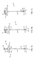
- FIGS. 3A-3C show another embodiment of a sheath inserter tool 500 that is similar to the embodiment of FIGS. 2A-2C , but that has a pistol-grip handle assembly.
- the tool 500 generally includes a handle 502, an actuator 504 slidably disposed within and extending through the handle 502, and an outer shaft 506 coupled to the actuator 504 and extending within and distally from the handle 502.
- the outer shaft 506 can include the fork on the distal end thereof, as previously described above with respect to FIGS. 1A-1C .
- the handle 502 has a generally elongate cylindrical configuration with a pistol-grip portion to facilitate grasping thereof.
- the handle 502 can have a blind bore extending therein from the distal end 502d and terminating just distal to the proximal-most end.
- the bore can be configured to receive the guidewire mated to the sheath, as shown, and a distal portion of the bore can receive the proximal end of the outer shaft 506 for mating the shaft to the actuator.
- the handle 502 can further include an elongate longitudinal cut-out 538a formed in a sidewall thereof and in communication with the inner lumen. The cut-out 538a can allow the actuator 504 on the inner component to extend therethrough and to slidably move there along.
- the actuator 504 is generally trigger-shaped and includes a distal facing finger-gripping surface 540a.
- the actuator 504 extends laterally outward from a side of the handle 502, and thus allows a user to place the pistol-grip portion of the handle 502 in their palm and to grasp the actuator 504 with one or two fingers to pull the actuator 504 proximally towards the pistol-grip portion of the handle 502.
- the actuator can thus slide proximally and distally relative to the handle.
- the actuator 504 can be fixedly mated to or integrally formed on the proximal end of the outer shaft 506. As a result, after the lock 514 is released, movement of the actuator 504 relative to the handle 502 moves the outer shaft 506 relative to the handle 502 and to the guidewire coupled to the sheath 100.
- the handle 502 includes a lock 514 disposed thereon that is similar to the lock 414 of FIGS. 2A-2C .
- the lock 514 can be moved into a locked position by pushing the lock 514 into the handle 502.
- the lock 514 prevents proximal movement of the actuator 504 and locks the outer shaft 506 from moving longitudinally with respect to the handle 502.
- the lock 514 In order to move the actuator 504 and the outer shaft 506 proximally relative to the handle 502 and the guidewire, the lock 514 must be moved to an unlocked position. This can be achieved by pressing the lock 514 so that it moves out and no longer blocks movement of the actuator 504. Proximal movement of the actuator 504 will retract the fork 508 from the sheath 100, as shown in FIG. 3C .
- FIGS. 4A-4B show another embodiment of a sheath inserter tool 600.
- the tool 600 includes an inner component having the fork thereon, and the inner component is moved proximally relative to an outer component and the guidewire.
- the tool 600 includes an outer component having a handle 602 with an outer shaft 606 extending distally therefrom, and an inner component that includes an actuator 604 in the form of a finger loop that is coupled to a proximal end of an inner shaft 610 that extends through the handle 602 the outer shaft 606.
- Movement of the inner shaft relative to the outer shaft is effective to move the fork between an extended position, in which the fork extends beyond a distal end of the outer shaft, and a retracted position, in which the fork is retracted into the outer shaft.
- the handle 602 in this embodiment has a generally T-shaped configuration with one side being in the form of a finger loop and the other side being in the form of a half-loop having a generally elongated arced shaped.
- This configuration allows a user to rest one finger, e.g., their pointer finger, against the half-loop, and to insert another finger, e.g., their middle finger, through the finger loop.
- the finger loop and half-loop that form the handle 602 can be integrally formed on or fixedly mated to a proximal end of the outer shaft 602. Both the outer shaft and the handle 602 can include a central lumen extending therethrough for slidably receiving the inner shaft 610.
- the actuator 604 which is positioned proximal to the handle 602 and which is coupled to the inner shaft 610, is generally loop-shaped and is configured to receive, for example, a user's thumb.
- the actuator 604 can be fixedly mated to or integrally formed on the proximal end of the inner shaft 610. As a result, movement of the actuator 604 relative to the handle 602 moves the inner shaft 610 relative to the outer shaft 606.
- the tool 600 can also include a lock 614 for locking the inner and outer shafts 610, 606 in a fixed position relative to one another.
- the lock 614 can be in the form of a removable structure that can be snapped onto the inner shaft 610 and that can also engage a flange or other feature (not shown) formed on a proximal end of the handle 602. When the lock 614 is mated to the inner shaft 610 and the handle 602, the inner and outer shafts 610, 606 are prevented from longitudinal movement.
- the device can be inserted through tissue or through a cannula in the locked position, and once the sheath is implanted within a bone hole, the lock 614 can be removed by moving the lock 614 laterally away from the device 600. With the lock removed, as shown in FIG. 4B , the actuator 604 and the inner shaft 610 can be moved proximally away from the handle 602 and outer shaft 610, thereby retracting the fork 608 out of the sheath 100 and into the outer shaft 606. The outer shaft 606 can remain in position, pressing the sheath into the bone hole.
- FIGS. 5A-B show another embodiment of a sheath inserter tool 700 that functions in a similar manner to the tool of FIGS. 4A-4B , but that includes a different handle assembly.
- the tool 700 includes an outer component having a handle 702 with an outer shaft 706 extending therefrom, and an inner component that includes an actuator 704 that is slidably coupled to an inner shaft 710 extending from the actuator 704 and through the handle 702 and the outer shaft 706.
- the handle 702 has a generally elongate cylindrical configuration to facilitate grasping thereof.
- the diameter can remain constant along the length of the handle 702, or a proximal or the handle can taper inward in a proximal direction, and a distal portion of the handle can taper inward in a distal direction, as shown.
- the handle 702 can have a bore extending entirely therethrough.
- the bore can be configured to slidably receive the inner shaft therethrough, and a distal portion of the bore can receive the proximal end of the outer shaft 706 for mating the outer shaft to the handle.
- Various mating techniques as described above can be used to fixedly mate the outer shaft 706 to the handle 702.
- the actuator 704 in this embodiment has a conical shape that tapers inward in a distal direction to form a distal facing finger-gripping surface 740a.
- the actuator 704 is positioned proximal of the handle 702 to thus allow a user to wrap their fingers around the handle, as indicated by the circles, and to place their thumb in the finger-gripping surface 740a to push the actuator 704 proximally upwards away from the handle 702.
- the actuator can thus slide proximally and distally relative to the handle 702.
- the actuator 704 can be fixedly mated to or integrally formed on the proximal end of the inner shaft 710. As a result, movement of the actuator 704 relative to the handle 702 moves the inner shaft 710 relative to the outer shaft 706.
- the device 700 further includes a lock 714 disposed on the inner shaft 710 and configured to engage the proximal portion of the handle 702.
- the handle 702 can include a flange or other feature that is engaged by the lock 714 so as to allow the lock 714 to prevent movement of the inner shaft 710 and the handle relative to one another.
- the lock 714 can alternatively engage the actuator 704, rather than the inner shaft 710, to prevent movement of the inner and outer components relative to one another.
- the lock 714 prevents proximal movement of the actuator 704 and locks the inner and outer shafts 710, 706 from moving longitudinally with respect to each other.
- the lock 714 can be removed from the device, as can be seen in FIG. 5B .
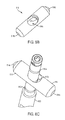
- FIGS. 6A and 7 show two additional embodiments of sheath inserter tools 800, 800', each of which includes an outer component having a handle 802, 802' with an outer shaft 806, 806' extending distally therefrom, and an inner component that includes an actuator 804, 804' that is positioned distal of the handle 802, 802' and that is mated to or integrally formed on the inner shaft 810, 810'.
- the actuator 804, 804' can extend through longitudinal slots in the outer shaft 806, 806', and the inner shaft 810 can be slidably disposed within the outer shaft 806, 806'. While not described in detail, a person skilled in the art will appreciate that the tools of FIGS. 6 and 7 can function as previously described with respect to FIGS. 4A-4B .
- Each handle 802, 802' can have a generally conical, knob-like configuration for allowing the handle to sit within a user's palm.
- the handles 802, 802' can include distal-facing recesses formed therein that are configured to seat the finger loop or loops on the actuator, as will be discussed below.
- Each handle 802, 802' can also have a blind bore extending therein from the distal end and terminating at a location distal to the proximal-most end.
- the bore can be configured to receive and releasably mate to a guidewire, as described above with respect to FIGS. 1A-1C .
- a distal portion of the bore can receive the proximal end of the outer shaft 806 for mating the shaft to the handle.
- the outer shaft 806 can further include two elongate longitudinal cut-outs 838a, 838b, as shown in FIG. 6A , or only a single cut-out 838a' as shown in FIG. 7 , formed in the sidewall thereof and in communication with the inner lumen.
- the cut-outs 838a, 838b, 838a' can allow the actuator 804 on the inner component to extend therethrough and to slidably move there along.
- the actuator 804 in FIG. 6A has first and second finger loops for receiving a user's fingers, e.g., the pointer and middle fingers.
- the actuator 804' in FIG. 7 only has a single finger loop for receiving a single finger, e.g., a pointer finger or thumb.
- Each actuator 804, 804' extends laterally outward from a sidewall of the outer shaft 806, 806', and thus allows a user to place the proximal end of the handle 802, 802' in their palm and to grasp the actuator 804, 804' with one or more fingers to pull the actuator 804, 804' proximally.
- the actuator can thus slide proximally and distally relative to the handle.
- the actuator 804, 804' can be fixedly mated to or integrally formed on a proximal portion of the inner shaft 810, 810'.
- the inner shaft 810 810' extends proximally beyond the actuator to allow the proximal end of the inner shaft to extend into the handle 802 and to be engaged by the lock 814, discussed below.
- movement of the actuator 804, 804' relative to the handle 802, 802' moves the inner shaft 810, 810' relative to the outer shaft 806, 806' and relative to a guidewire coupled to the handle 802, 802'.
- Each tool can further include a lock 814 extending through the handle 802, as seen in FIG. 6A . While only FIG. 6A illustrates a lock, a person skilled in the art will appreciate that the tool of FIG. 7 can likewise include a lock.
- the lock 814 is shown in more detail in FIGS. 6B-6D , and is generally in the form of an elongate member having a central opening or elongate cut-out 814c formed therein. As shown in FIG. 6B , the cut-out 814c can include an engagement feature 814e, such as a protrusion or ledge, that is configured to be moved in and out of one or more grooves formed in the proximal end of the inner shaft 810.
- one end of the lock 814 can include a bump 814a formed therein and the other end of the lock 814 can include a recess 814b formed therein.
- the engagement feature 814e can be formed within the cut-out 814c at a location adjacent to the bump 814a, such that the bump 814a can indicate the closed positioned, whereas the recess 814b can indicate the open position, as will be discussed in more detail below.
- the proximal end of the inner shaft 810 can include three grooves 815a, 815b, 815c formed therein and spaced longitudinally there along.
- the proximal-most groove 815a can correspond to a position in which the inner shaft 810 is fully extended relative to the outer shaft 806, the distal-most groove 815c can correspond to a position in which the inner shaft 810 is fully retracted relative to the outer shaft 806, and the middle groove 815b can correspond to a mid-position between the fully extended and fully retracted positions.
- the inner shaft 810 can include any number of grooves formed therein as may be desired.
- FIG. 6C illustrates the lock 814 engaged in the middle position with the middle groove 815b, with the bump 814a positioned closer to the inner shaft 810 than the recess 814b. The inner shaft 810 is thus preventing from moving relative to the outer shaft 806. Pressing on the recess 814b to slide the lock 814 relative to the handle 802 will move the engagement feature 814e out of engagement with the groove 815b, thus allowing free slidable movement of the inner shaft 810 relative to the outer shaft 806.
- the inner shaft can also include features that resist movement of the inner shaft relative to the outer shaft when the lock 814 is disengaged. Such features can also include the position of the inner shaft relative to the proximal-most, middle, and distal-most positions as defined by the grooves 815a-c.
- a collar 816 is disposed around the proximal end of the inner shaft 806 and it includes opposed elongate slots 817, 819 formed therein. While only slot 817 is discussed, it will be appreciated that slot 819 can include the same features and can function in the same manner.
- slot 817 can include a three notches formed therein, a proximal-most notch 817p, a middle notch 817m, and a distal notch 817d.
- Each notch 817p, 817m, 817d can be configured to frictionally engage a pin 810p formed on or coupled to the proximal end of the inner shaft 810, at a location above the grooves 815a-c. The notches can engage the pin to hinder but not prevent movement.
- each notch 817p, 817m, 817d can be positioned such that, when the pin 810p is seated therein, the button 814 will be aligned with the corresponding proximal, middle, or distal grooves 815a-c.
- the collar 816 can include side slots 821a, 821b formed on opposed sides thereof.
- the side slots 821a, 821b allow the sidewalls surrounding slot 817 to flex as the pin 810p is moved into a notch 817p, 817m, 817d.
- FIGS. 6E-6G illustrate a button 842 that is configured to releasably engage the guidewire G extending through the shaft 806.
- the button includes a head 842h and shaft 842s extending therefrom.
- the shaft 842s includes a slot or cut-out 842c formed in the distal end thereof for engaging the guidewire G.
- the cut-out 842c is configured to snap onto the guidewire G to prevent movement of the guidewire G relative to the button 842.
- the outer shaft 806 can include an opening 842a formed therein for receiving the button 842. In use, the button 842 can be pressed through the opening 842a to cause the cut-out 842c to engage the guidewire G, and removing the button can release the guidewire G.
- FIG. 8 shows another embodiment of a sheath inserter tool 900 that functions in a similar manner as described above.
- the tool includes an outer component having a handle 902 with an outer shaft 906 extending therefrom, and an inner component that includes an actuator 904 that is coupled to the inner shaft 910, which extends through the handle 902 and the outer shaft 906.
- the handle 902 has a generally elongate cylindrical configuration to facilitate grasping thereof.
- the handle 902 can have a bore extending entirely therethrough.
- the bore can be configured to slidably receive the inner shaft therethrough, and a distal portion of the bore can receive the proximal end of the outer shaft 906 for mating the shaft to the handle.
- the handle 902 can further include a side cut-out 938a formed in a sidewall thereof and a top cut-out or opening 938b formed in the proximal-most end thereof.
- the side cut-out 938a can allow a lateral finger grip 940a to extend therethrough, and the top cut-out 938b can allow a proximal finger grip 940b to extend therethrough.
- the actuator 904 is generally conical and includes a biasing element 905 (such as a spring) proximal to the inner shaft 910 in the handle 902 that, in a compressed state, results in the fork 908 being in a fully extended position when the sheath 100 is mated to the tool (as shown in FIG. 8 ).
- the actuator 904 can be actuated by pressing the lateral finger grip 940a radially inward toward the handle 902 until the surface 940a is within the handle. This radially inward movement causes the biasing element 905 to be released from the compressed state.
- the release of the biasing element 905 will cause the biasing element 905 to move proximally to an elongated, relaxed state, which will cause the inner shaft 910 to move proximally with respect to the outer shaft 906 and handle 902, thereby retracting the fork 908 from the sheath 100 and into the outer shaft.
- the movement will cause the proximal finger grip 940b to move proximally relative to the handle 902.
- Distal movement of the proximal finger grip 940b can reverse the retraction, causing the biasing element 905 to re-compress by moving the spring distally into a compressed state until the lateral finger grip 940a can again extend through the cut-out 938a.
- This movement will cause the inner shaft 910 to move distally again.
- a user can place the elongate cylindrical configuration of the handle 902 in their palm and manipulate the actuator 904 with, for example, a thumb.
- the actuator 904 can be fixedly mated to or integrally formed on the proximal end of the inner shaft 910. As a result, movement of the actuator 904 relative to the handle 902 moves the inner shaft 910 relative to the outer shaft 906.
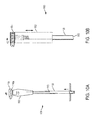
- FIG. 9 shows a proximal portion of another embodiment of a sheath inserter tool 1000 that can function as previously described with respect to FIGS. 4A-4B .
- the tool 1000 includes an outer component having a handle 1002 with an outer shaft 1006 extending therefrom, and an inner component that includes an actuator 1004 that is slidably disposed relative to the handle 1002 and that is coupled to an inner shaft 1010 extending through the handle and through the outer shaft 1006.
- the distal end can be similar to the aforementioned embodiments, with the inner shaft including a fork thereon as described with respect to FIGS. 1A-1C .
- the handle 1002 has a generally elongate cylindrical configuration to facilitate grasping thereof.
- the handle 1002 can have a blind bore extending therethrough from the distal end 1002d and terminating just distal to the proximal-most end.
- the bore can be configured to receive a proximal end of a guidewire mated to a sheath. While not shown, the bore can include a guidewire grasper for releasably engaging the guidewire, as discussed above.
- a distal portion of the bore can receive the proximal end of the outer shaft 1006 for mating the shaft to the handle.
- the handle 1002 can further include an elongate longitudinal cut-out 1038a formed in a sidewall thereof and in communication with the inner lumen. The cut-out 1038a can allow the actuator 1004 on the inner component to extend therethrough and to slidably move there along.
- the actuator 1004 is in the form of a sliding button or knob that includes a finger-gripping surface 1040a.
- the actuator 1004 extends laterally outward from a side of the handle 1002, and thus allows a user to place the handle 1002 in their palm and to manipulate the actuator 1004 with fingers, for example a thumb, to move the actuator 1004 proximally and distally relative to the handle.
- the actuator 1004 can be fixedly mated to or integrally formed on the proximal end of the inner shaft 1010.
- the handle 1002 can also include a lock (not shown).
- FIGS. 10A-10B show another embodiment of a sheath inserter tool 1100 that functions in a similar manner to the aforementioned embodiments, and that generally includes an outer component having a handle 1102 with an outer shaft 1106 extending therefrom, and an inner component that includes an actuator 1104 that is positioned proximal to the handle 1102 and that is coupled to a proximal end of an inner shaft 1110 extending through the handle 1102 and through the outer shaft 1106.
- the handle 1102 has a generally elongate cylindrical configuration to facilitate grasping thereof.
- the handle 1102 can have a bore extending entirely therethrough for receiving the inner shaft.
- a distal portion of the bore can receive the proximal end of the outer shaft 1106 for mating the shaft to the handle.
- the bore can allow the actuator 1104, or a portion thereof, on the inner component to extend therethrough and to rotatably move thereabove.
- the actuator 1104 is generally disc-shaped and includes a finger-gripping surface 1140a.
- the actuator 1104 is positioned at a proximal end of the handle 1102, and thus allows a user to place the elongate cylindrical configuration of the handle 1102 in their palm and to manipulate the actuator 1104 with, for example, a thumb to rotate the actuator 1104 relative to the handle 1102.
- the actuator 1104 can be threadably mated to the proximal end of the inner shaft 1110.
- the actuator 1104 can include a cylindrical shaft extending longitudinally from the disc-shaped portion and having threads formed therein that are configured to mate with threads on a proximal end of the inner shaft.
- the actuator 1104 can be coupled to the handle 1102 such that it is freely rotatable, but is prevented from moving axially. As a result, rotation of the actuator 1104 relative to the handle 1102 moves the inner shaft 1110 relative to the outer shaft 1106. Rotation of the actuator 1104 can thus cause proximal movement of the inner shaft 1110 relative to the handle 1102 and outer shaft 1110 to thereby retract a fork on the inner shaft from a sheath and into the outer shaft.
- the handle 1102 can also include a lock (not shown). The lock can be incorporated into the actuator 1104, for example by using ball and detents that retain the actuator 1104 in one or more positions.
- FIGS. 11A-11C show another embodiment of a sheath inserter tool 1200 having an outer component with a handle 1202 with an outer shaft 1206 extending distally therefrom, and an inner component that includes an actuator 1204 that is pivotably coupled to the handle 1202 and that is coupled to an inner shaft 1210 extending through the outer shaft 1206.
- the tool functions in a similar manner as described above with respect to FIGS. 4A-4B , with the inner shaft having a fork on a distal end thereof that is movable between extended and retracted positions.
- the handle 1202 in this embodiment has a generally elongate cylindrical configuration to facilitate grasping thereof.
- the handle 1202 can have a blind bore extending therethrough from the distal end 1202d and terminating just distal to the proximal-most end.
- the bore can be configured to receive a guidewire coupled to the sheath, and it can optionally include components for releasably engaging the guidewire.
- a distal portion of the bore can receive the proximal end of the outer shaft 1206 for mating the shaft to the handle.
- the actuator 1204 in this embodiment is generally lever-shaped and includes finger-gripping surface 1240a.
- the actuator 1204 is pivotably attached to the handle 1202 and extends laterally outward in a resting position from a side of the handle 1202, as shown in FIG. 11A . This allows a user to place the handle 1202 in their palm and to manipulate the actuator 1204 with their fingers (as indicated by the circles) to squeeze and pivotally move the actuator 1204 toward the handle 1202.
- a linkage 1207 extends from a proximal end of the actuator 1204 and is coupled to a distal end of a biasing element, e.g., a spring 1209 located inside the handle 1202. The spring is positioned proximal to the inner shaft 1210 and is coupled to the inner shaft 1210.
- the biasing element of the actuator 1204 causes the fork 1208 on the inner shaft to be in a fully extended position, extending from the outer shaft 1206.
- the linkage upon pivotal movement of the actuator 1204 relative to the handle 1202, the linkage causes the spring to compress proximally, thereby moving the inner shaft proximally relative to the outer shaft 1206 to retract the fork 1208 into the outer shaft.
- the handle 1202 can also include a lock (not shown) which can be separate from or incorporated into the actuator 1204.
- tools discussed above can have a variety of configurations.
- the handle can be integrally formed on the outer shaft or the outer shaft can be mated to a distal facing surface of the handle without the need to extend into the handle.
- Other similar modifications can be made as needed to connect the various components.
- FIGS. 12-14 show embodiments of a sheath alignment feature that can be included in an inserter tool, including any of the inserter tools discussed above.
- FIG. 12 shows an outer shaft 1306 and inner shaft 1310.
- a fork 1308 is formed on or mated to the distal end of the inner shaft 1310, and the fork 1308 includes first and second elongate prongs 1324a, 1324b extending longitudinally from opposed sides of the inner shaft 1310.
- the outer shaft 1306 includes a sheath alignment feature 1312 formed on a distal end thereof and having a generally cone-shaped configuration, tapering inward in a distal direction.
- the shape can be configured to match the shape of an inner lumen or bore in a sheath so as to allow the sheath alignment feature to be received within the sheath when the sheath is mated to the inserter tool.
- the sheath alignment feature 1312 can further include cut-outs or openings formed in opposed sides adjacent to the proximal end for receiving the prongs therethrough.
- the sheath alignment feature 1312 can have a proximal portion having a diameter that is smaller than the diameter of the distal end of inner shaft.
- first and second elongate prongs 1324a, 1324b on the inner shaft 1310 can extend through the cut-outs in the sheath alignment feature (or the distal end of the outer shaft) and to extend along opposed sides of the sheath alignment feature 1312.
- the sheath alignment feature can extend into a sheath coupled to the tool, thereby facilitating alignment of the sheath with respect to the tool.
- the prongs can extend along the sheath alignment feature and along opposed sidewalls slots in the sheath.
- FIG. 13 shows another embodiment of a sheath alignment feature 1362 that is similar to the embodiment of FIG. 14 , but that includes elongate cut-outs formed in opposed sides of the sheath alignment feature 1362.
- the inner shaft 1360 includes a fork 1358 first and second elongate prongs 1374a, 1374b that extend longitudinally along opposed sides of the sheath alignment feature 1362 on the outer shaft 1360.
- the sheath alignment feature includes first and second opposed cut-outs 1375a, 1375b formed therein and configured to receive the first and second elongate prongs 1374a, 1374b.
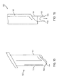
- FIG. 14 shows another embodiment of a distal portion of an insertion tool that is similar to the embodiments of FIGS. 12 and 13 , but that includes an elongate slot in the outer shaft 1406 for receiving the forks on the inner shaft 1410.
- the distal end of the outer shaft 1406 is closed with an elongate slot 1416 formed therein.
- the elongate slot is dimensioned and configured for receiving first and second prongs 1424a, 1424b of fork 1408 such that the first and second prongs 1424a, 1424b can extend distally from the distal end of inner shaft 1410, as with other embodiments.
- a sheath alignment feature 1412 is formed on the fork 1408 between the first and second prongs 1424a, 1424b.
- the illustrated sheath alignment feature 1412 has a generally cone-shaped configuration, tapering inward in a distal direction.
- FIGS. 15-20 illustrate various tools for maintaining tension on a tendon during anchoring of the tendon. These features can be incorporated into an inserter tool, including any of the inserter tools discussed above, or they can be provided on a separate tool, such as a cannula.
- FIGS. 15-17 illustrate one embodiment of a tool, in the form of a cannula that includes an outer shaft 1502 having a distal end 1502d with a saddled or beveled edge 1506 forming an angled viewing window.
- the beveled edge 1506 can be rounded and can extend cross-sectionally through the shaft 1502 from a first sidewall 1510 to a second sidewall 1512 on the opposite side of the shaft 1502, such that the first sidewall 1510 extends a distance distally beyond the second sidewall 1512. Such a configuration will result in an opening through the second sidewall 1512 when the cannula 1500 is positioned against tissue and bone, as shown in FIG. 17 .
- a forked inserter tool 1514 can be passed through the outer shaft 1502 to allow prongs 1518a, 1518b on the forked distal end 1516 to be used to advance a tendon into a bone hole.
- the forked inserter tool 1514 can move axially relative to the outer shaft 1502 to retract and extend the prongs 1518a, 1518b into and from the outer shaft 1502.
- the distal-most end of the outer shaft 1502 can be positioned on a tendon T against bone B to pinch the tendon T to be anchored and thereby prevent slippage of the tendon T.
- the outer shaft 1502 is preferably positioned on a side of the bone hole H that the tendon extends from, e.g., the distal side of a bone hole on the humerus for a biceps tenodesis procedure.
- the outer shaft will thus maintain a tension of the tendon T, while the forked inserter tool is extended to push or dunk the tendon into the bone hole.
- the fork can have a sheath loaded thereon that is inserted into the bone hole to maintain the tendon in the bone hole.
- the cannula or outer shaft of an inserter tool can include various features formed thereon to resist backout or any unintentional proximal movement of the outer shaft during use.
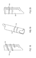
- FIG. 18 illustrates threads 1522 formed on an outer shaft 1520
- FIGS. 19 and 20 illustrate ribs 1532 formed on the outer shaft 1530.
- the threads and ribs can provide resistance against the surrounding tissue to resist any unintentional proximal movement of the outer shaft.
- the distal portion of the outer shaft can be free of surface features.
- the distal portion of the outer shaft can be formed from a transparent material, can include a compressible material, and/or can have smooth surface.
- a sheath inserter can include a distal end having movable tendon engagement features.
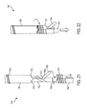
- an inserter tool 1600 is provided and includes an outer shaft 1602 coupled to a handle as discussed above and an inner shaft 1604 having a tendon engagement member 1606.
- the tendon engagement member 1606 can be in the form of a pivotable arm having a proximal end that is coupled to the inner shaft 1604 via a hinge 1610 or similar attachment mechanism.
- the distal end of the tendon engagement member 1606d can move laterally away from and rotate about the axis of the hinge.
- the distal end of the inner shaft 1604d can be inserted into an anchor 1620.
- the anchor 1620 can have an inner lumen 1624 to receive the distal end of the inner shaft 1604d, ribs 1622 formed thereon and a recess feature 1626 to receive the tendon engagement feature. As shown in FIG. 22 , when the anchor 1620 is coupled to the inserter 1600 the proximal end of the anchor 1620p abuts the distal end of the outer shaft 1602d. The distal end of the inner shaft 1604d can extend through the inner lumen 1624 and past the distal end of the anchor 1620d.
- the tendon engagement feature 1606 can be advanced and articulated to grab the tendon and pull the tendon proximate to the anchor 1620. The inserter 1600 can then be advanced to position the tendon and the anchor 1620 inside the bone hole.
- the tension on the tendon is thus maintained by the inserter tool during insertion of the tendon into the bone hole.
- the anchor 1620 is illustrated with threads formed thereon, the anchor can be non-threaded or can include along only portions or the entire length thereof.
- FIGS. 23-31 illustrate various embodiments of a sheath/fork protector that is configured to cover a sheath/fork and optionally a distal portion of a sheath inserter tool during insertion through tissue, and/or that facilitates insertion of the device through tissue.
- FIG. 23 shows a disposable, thin-walled sheath protector 2105 that effectively covers a sheath 2106, a fork with prongs 2107, and a distal end of an inserter 2108.
- the sheath protector 2105 has a generally elongate cylindrical configuration with a conical distal tip.
- the conical distal tip can function as an obturator to facilitate penetration through tissue percutaneously.
- the length of the sheath protector can be configured to allow the sheath protector 2105 to extend over a portion of the distal end of the outer shaft.
- a proximal end of the sheath protector 2105 can include a tab extending radially outward therefrom to facilitate grasping of the sheath protector.
- the sheath protector is inserted through tissue in the position shown in FIG. 23 .
- the tab on the proximal end can then be grasped and the sheath protector can be slid proximally along the outer shaft to expose the sheath and the distal end of the inserter tool once inserted.
- the distal conical portion of the sheath protector can include one or more slits formed therein to allow the distal end to open up and expand around the sheath and outer shaft.
- FIGS. 24-25 show another embodiment of a sheath protector 2121 with an angled distal tip 2121d, which can assist in accurate insertion in procedures when narrow or small insertion points are required.
- FIG. 26 shows another embodiment where the sheath protector 2130 has a semi-cylindrical shape and is open along its entire longitudinal length. The sheath protector can be inserted through tissue to provide a pathway or slide for insertion of the sheath/fork. The fork 2131 and sheath 2132 can be introduced by sliding them along the open sheath protector 2130.
- FIG. 27 shows another embodiment of a bullet-shaped sheath/fork protector 2140.
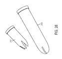
- FIG. 28 shows two sheath/fork protectors 2150, 2151 having different sizes for use with different sized sheaths
- FIG. 29 shows a sheath protector 2160 covering a distal end of an inserter with a sheath.
- the sheath protectors can be configured with distal tips designed to separate (open and close) upon distal movement of the inserter and sheath.
- FIGS. 30 and 31 the sheath 2171 and the inserter 2172 with a fork 2173 can be advanced through the distal end of the sheath protector 2170 for allowing plunging of the sheath into a bone hole.
- FIG. 31 shows the sheath 2171 and the sheath inserter 2172 including the fork and the shaft extending beyond the distal tip of the sheath protector 2170.
- the distal tip 2170d of the sheath protector 2170 can be configured to assist the distal penetration of the sheath 2171 and inserter 2172 with fork 2173 through skin.
- the sheath protector 2170 can be designed with slits to allow the distal tip 2170d to remain closed during insertion thus preventing the forks or sheath from catching on tissue, and once inserted through tissue to flare open upon distal movement.
- the devices disclosed herein can be designed to be disposed of after a single use, or they can be designed to be used multiple times. In either case, however, the device can be reconditioned for reuse after at least one use. Reconditioning can include any combination of the steps of disassembly of the device, followed by cleaning or replacement of particular pieces, and subsequent reassembly. In particular, the device can be disassembled, and any number of the particular pieces or parts of the device can be selectively replaced or removed in any combination. Upon cleaning and/or replacement of particular parts, the device can be reassembled for subsequent use either at a reconditioning facility, or by a surgical team immediately prior to a surgical procedure.
- reconditioning of a device can utilize a variety of techniques for disassembly, cleaning/replacement, and reassembly. Use of such techniques, and the resulting reconditioned device, are all within the scope of the present application.
- the invention described herein will be processed before surgery.
- a new or used instrument is obtained and if necessary cleaned.
- the instrument can then be sterilized.
- the instrument is placed in a closed and sealed container, such as a plastic or TYVEK bag.
- the container and instrument are then placed in a field of radiation that can penetrate the container, such as gamma radiation, x-rays, or high-energy electrons.
- the radiation kills bacteria on the instrument and in the container.
- the sterilized instrument can then be stored in the sterile container.
- the sealed container keeps the instrument sterile until it is opened in the medical facility.
- device is sterilized. This can be done by any number of ways known to those skilled in the art including beta or gamma radiation, ethylene oxide, steam.
Priority Applications (1)
| Application Number | Priority Date | Filing Date | Title |
|---|---|---|---|
| EP21174333.1A EP3888593A1 (de) | 2014-10-23 | 2015-10-22 | Bizepstenodeseabgabewerkzeuge |
Applications Claiming Priority (2)
| Application Number | Priority Date | Filing Date | Title |
|---|---|---|---|
| US201462067701P | 2014-10-23 | 2014-10-23 | |
| US14/610,730 US10076374B2 (en) | 2014-10-23 | 2015-01-30 | Biceps tenodesis delivery tools |
Related Child Applications (1)
| Application Number | Title | Priority Date | Filing Date |
|---|---|---|---|
| EP21174333.1A Division EP3888593A1 (de) | 2014-10-23 | 2015-10-22 | Bizepstenodeseabgabewerkzeuge |
Publications (2)
| Publication Number | Publication Date |
|---|---|
| EP3020372A1 true EP3020372A1 (de) | 2016-05-18 |
| EP3020372B1 EP3020372B1 (de) | 2021-05-19 |
Family
ID=54360052
Family Applications (2)
| Application Number | Title | Priority Date | Filing Date |
|---|---|---|---|
| EP15191013.0A Active EP3020372B1 (de) | 2014-10-23 | 2015-10-22 | Bizepstenodese abgabewerkzeug |
| EP21174333.1A Pending EP3888593A1 (de) | 2014-10-23 | 2015-10-22 | Bizepstenodeseabgabewerkzeuge |
Family Applications After (1)
| Application Number | Title | Priority Date | Filing Date |
|---|---|---|---|
| EP21174333.1A Pending EP3888593A1 (de) | 2014-10-23 | 2015-10-22 | Bizepstenodeseabgabewerkzeuge |
Country Status (7)
| Country | Link |
|---|---|
| US (2) | US10076374B2 (de) |
| EP (2) | EP3020372B1 (de) |
| JP (1) | JP6644514B2 (de) |
| CN (1) | CN105769272B (de) |
| AU (2) | AU2015243097B2 (de) |
| BR (1) | BR102015026750B1 (de) |
| CA (1) | CA2909960A1 (de) |
Cited By (1)
| Publication number | Priority date | Publication date | Assignee | Title |
|---|---|---|---|---|
| WO2024003170A1 (de) * | 2022-07-01 | 2024-01-04 | Inovedis Gmbh | Werkzeugsatz zur implantation eines sehnenfixationsimplantats |
Families Citing this family (19)
| Publication number | Priority date | Publication date | Assignee | Title |
|---|---|---|---|---|
| US10729419B2 (en) | 2014-10-23 | 2020-08-04 | Medos International Sarl | Biceps tenodesis implants and delivery tools |
| US10856966B2 (en) | 2014-10-23 | 2020-12-08 | Medos International Sarl | Biceps tenodesis implants and delivery tools |
| US10751161B2 (en) | 2014-10-23 | 2020-08-25 | Medos International Sárl | Biceps tenodesis anchor implants |
| US10034742B2 (en) | 2014-10-23 | 2018-07-31 | Medos International Sarl | Biceps tenodesis implants and delivery tools |
| US10076374B2 (en) * | 2014-10-23 | 2018-09-18 | Medos International Sárl | Biceps tenodesis delivery tools |
| US9693856B2 (en) * | 2015-04-22 | 2017-07-04 | DePuy Synthes Products, LLC | Biceps repair device |
| CA2983341A1 (en) | 2015-05-06 | 2016-11-10 | Rotation Medical, Inc. | Medical implant delivery system and related methods |
| EP3397175B1 (de) * | 2015-12-31 | 2021-11-24 | Rotation Medical, Inc. | Befestigungsmittelabgabesystem |
| US10231823B2 (en) | 2016-04-08 | 2019-03-19 | Medos International Sarl | Tenodesis implants and tools |
| US10231824B2 (en) | 2016-04-08 | 2019-03-19 | Medos International Sárl | Tenodesis anchoring systems and tools |
| US10624734B2 (en) | 2016-10-18 | 2020-04-21 | Arthrex, Inc. | Surgical assembly for tissue repair |
| US10582925B2 (en) * | 2017-02-06 | 2020-03-10 | Medos International Sarl | Devices, systems, and methods for knotless suture anchors |
| CA3131775A1 (en) * | 2019-02-28 | 2020-09-03 | Paragon 28, Inc. | Implants, systems, and methods of use |
| US11730529B2 (en) | 2020-03-26 | 2023-08-22 | Warsaw Orthopedic, Inc. | Powered modular head locker |
| EP4125714A1 (de) * | 2020-04-03 | 2023-02-08 | Smith&Nephew, Inc. | System zur einführung eines medizinischen implantats |
| US11291477B1 (en) | 2021-05-04 | 2022-04-05 | Warsaw Orthopedic, Inc. | Dorsal adjusting implant and methods of use |
| US11432848B1 (en) | 2021-05-12 | 2022-09-06 | Warsaw Orthopedic, Inc. | Top loading quick lock construct |
| US11712270B2 (en) | 2021-05-17 | 2023-08-01 | Warsaw Orthopedic, Inc. | Quick lock clamp constructs and associated methods |
| US11957391B2 (en) | 2021-11-01 | 2024-04-16 | Warsaw Orthopedic, Inc. | Bone screw having an overmold of a shank |
Citations (5)
| Publication number | Priority date | Publication date | Assignee | Title |
|---|---|---|---|---|
| US5702398A (en) * | 1997-02-21 | 1997-12-30 | Tarabishy; Sam | Tension screw |
| WO2001030253A1 (en) * | 1999-10-26 | 2001-05-03 | Dr S. Fine & Dr G. Shar Pty Ltd | Orthopaedic ligament fixation system |
| US20040193217A1 (en) * | 1996-09-13 | 2004-09-30 | Tendon Technology, Ltd. | Apparatus and methods for tendon or ligament repair |
| US20100106194A1 (en) * | 2004-10-26 | 2010-04-29 | P Tech, Llc | Stabilizing a spinal anatomical structure |
| WO2012129617A1 (pt) * | 2011-03-28 | 2012-10-04 | Medvale Pesquisa E Desenvolvimento Das Ciências Físicas E Naturais Ltda. | Dispositivos de fixação córtico-esponjosa-compressiva para cirurgia de reconstrução ligamentar do joelho com dupla banda e túneis femoral e tibial únicos |
Family Cites Families (352)
| Publication number | Priority date | Publication date | Assignee | Title |
|---|---|---|---|---|
| US651949A (en) | 1899-10-05 | 1900-06-19 | Theron R Lillie | Screw holder and driver. |
| US775427A (en) | 1904-05-02 | 1904-11-22 | Charles Lusted Sr | Screw holder and driver. |
| US1426320A (en) | 1921-11-28 | 1922-08-15 | Peter M Savage | Holder for screws, nails, and the like |
| US1925385A (en) | 1932-11-08 | 1933-09-05 | Homer C Humes | Screw driver with screw holders |
| US2243717A (en) | 1938-09-20 | 1941-05-27 | Moreira Franciseo Elias Godoy | Surgical device |
| US2288584A (en) | 1940-05-23 | 1942-06-30 | Harry Herschel Leiter | Surgeon's screw driver, screw holder, and stabilizer |
| US2381050A (en) | 1943-12-04 | 1945-08-07 | Mervyn G Hardinge | Fracture reducing device |
| US2484655A (en) | 1947-07-14 | 1949-10-11 | Clifford B Shreve | Screw holder for screw drivers |
| US3073189A (en) | 1960-09-30 | 1963-01-15 | Stalker Drill Works Ltd | Drills |
| US3103926A (en) | 1961-01-13 | 1963-09-17 | Orthopaedic Specialties Corp | Surgical bone pin |
| US3089359A (en) | 1961-05-08 | 1963-05-14 | Nat Twist Drill & Tool Company | Drill construction |
| US3130763A (en) | 1962-09-13 | 1964-04-28 | Schlosser Bernard | Drills for cutting wooden plugs with cross grain |
| US3298410A (en) | 1964-01-31 | 1967-01-17 | Morifuji Haguruma Seisakusho C | Screw holder structure for use with screw drivers |
| GB2084468B (en) | 1980-09-25 | 1984-06-06 | South African Inventions | Surgical implant |
| US4641640A (en) * | 1982-01-18 | 1987-02-10 | Calvin Griggs | Compression screw assembly |
| US4512344A (en) * | 1982-05-12 | 1985-04-23 | Barber Forest C | Arthroscopic surgery dissecting apparatus |
| DE3309860A1 (de) | 1983-02-08 | 1984-08-09 | Fa. Gottlieb Gühring, 7470 Albstadt | Bohrwerkzeug |
| US4503737A (en) | 1983-04-11 | 1985-03-12 | Digiovanni Donald | Threaded fastener removing tool |
| US4687392A (en) | 1984-04-17 | 1987-08-18 | Bidwell Robert E | Torque limiting fastener |
| US4592346A (en) | 1985-04-08 | 1986-06-03 | Jurgutis John A | Orthopedic staple |
| US4711232A (en) | 1985-07-12 | 1987-12-08 | Artur Fischer | Bone fastener and method of installing same |
| US4640271A (en) | 1985-11-07 | 1987-02-03 | Zimmer, Inc. | Bone screw |
| US4884572A (en) | 1986-05-20 | 1989-12-05 | Concept, Inc. | Tack and applicator for treating torn bodily material in vivo |
| US4919130A (en) | 1986-11-07 | 1990-04-24 | Nestle S.A. | Tool for inserting compressible intraocular lenses into the eye and method |
| US4901717A (en) | 1987-01-05 | 1990-02-20 | Moore Robert R | Tendon leader |
| US4773417A (en) | 1987-01-05 | 1988-09-27 | Moore Robert R | Method for using a tendon stripper and leader set |
| US4858810A (en) | 1987-04-30 | 1989-08-22 | Heart Technology, Inc. | Quick acting pin vise for use with angiographic guidewires |
| DE3818652A1 (de) | 1988-06-01 | 1989-12-14 | Fischer Artur Werke Gmbh | Spreizduebel aus kunststoff |
| US4960420A (en) | 1988-08-23 | 1990-10-02 | Marlowe Goble E | Channel ligament clamp and system |
| US4871289A (en) | 1988-11-25 | 1989-10-03 | Olympic Manufacturing Group, Inc. | Expansion fastener |
| US4988351A (en) | 1989-01-06 | 1991-01-29 | Concept, Inc. | Washer for use with cancellous screw for attaching soft tissue to bone |
| US4950270A (en) | 1989-02-03 | 1990-08-21 | Boehringer Mannheim Corporation | Cannulated self-tapping bone screw |
| US5129906A (en) | 1989-09-08 | 1992-07-14 | Linvatec Corporation | Bioabsorbable tack for joining bodily tissue and in vivo method and apparatus for deploying same |
| GB8924806D0 (en) | 1989-11-03 | 1989-12-20 | Neoligaments Ltd | Prosthectic ligament system |
| US5029573A (en) | 1990-03-30 | 1991-07-09 | Chow James C | System for endoscopic surgery |
| US5236445A (en) | 1990-07-02 | 1993-08-17 | American Cyanamid Company | Expandable bone anchor and method of anchoring a suture to a bone |
| US5746743A (en) | 1990-07-13 | 1998-05-05 | Greenberg Surgical Technologies, Llc | Single-handed surgical drill depth guide with mandibular retractor |
| US5026376A (en) | 1990-07-13 | 1991-06-25 | Greenberg Alex M | Surgical drill guide and retractor |
| US5133720A (en) | 1990-07-13 | 1992-07-28 | Greenberg Alex M | Surgical drill guide and retractor |
| DE69127977T2 (de) | 1990-09-04 | 1998-09-17 | Smith & Nephew Inc N D Ges D S | Chirurgische schraube |
| US7074203B1 (en) * | 1990-09-25 | 2006-07-11 | Depuy Mitek, Inc. | Bone anchor and deployment device therefor |
| US5180384A (en) | 1991-02-08 | 1993-01-19 | Mikhail Michael W E | Method for implanting a patellar prosthesis |
| US5234435A (en) | 1991-03-08 | 1993-08-10 | Seagrave Jr Richard A | Surgical method and apparatus |
| CA2063159C (en) | 1991-03-22 | 1999-06-15 | Thomas W. Sander | Orthopedic fastener |
| US5720753A (en) | 1991-03-22 | 1998-02-24 | United States Surgical Corporation | Orthopedic fastener |
| US5105690A (en) | 1991-03-29 | 1992-04-21 | Implant Innovations, Inc. | Manipulator-driver for holding and driving a screw-type article |
| US5203864A (en) | 1991-04-05 | 1993-04-20 | Phillips Edward H | Surgical fastener system |
| DE69206693T2 (de) | 1991-05-24 | 1996-05-23 | Synthes Ag | Resorbierbare Sehnen- und Knochenverstärkungseinrichtung |
| US5116337A (en) | 1991-06-27 | 1992-05-26 | Johnson Lanny L | Fixation screw and method for ligament reconstruction |
| FR2678823B1 (fr) | 1991-07-11 | 1995-07-07 | Legrand Jean Jacques | Dispositif de renforcement d'un ligament au cours d'une plastie ligamentaire. |
| US5282816A (en) | 1991-09-20 | 1994-02-01 | Milres Corporation | Apparatus for subligamentous endoscopic transverse carpal ligament release surgery |
| US5325883A (en) | 1991-11-04 | 1994-07-05 | Orr Terrence R | Device and method for carpal tunnel release |
| US5226890A (en) | 1991-11-13 | 1993-07-13 | United States Surgical Corporation | Tissue gripping device |
| US5273024A (en) | 1992-01-22 | 1993-12-28 | Linvatec Corporation | Method and apparatus for performing endoscopic surgery |
| US5320626A (en) | 1992-02-19 | 1994-06-14 | Arthrex Inc. | Endoscopic drill guide |
| US5211647A (en) | 1992-02-19 | 1993-05-18 | Arthrex Inc. | Interference screw and cannulated sheath for endosteal fixation of ligaments |
| US5425733A (en) | 1992-02-19 | 1995-06-20 | Arthrex, Inc. | Interference screw with rounded back end and cannulated sheath for endosteal fixation of ligaments |
| US5385541A (en) | 1992-04-24 | 1995-01-31 | Loma Linda University Medical Center | Cerebrospinal fluid shunt capable of minimal invasive revision |
| DE69317654T2 (de) | 1992-04-28 | 1998-10-01 | Donald R Huene | Absorbierbare knochenschraube und werkzeug zum einsetzen derselben |
| US5242418A (en) | 1992-05-22 | 1993-09-07 | Weinstein James D | Protective means for a needle or similar cannula medical device |
| US5226714A (en) | 1992-05-26 | 1993-07-13 | Wright Jack V | Pivoting drawer slide system |
| US5250055A (en) | 1992-06-08 | 1993-10-05 | Orthopedic Systems Inc. | Method and apparatus for tying suture to bone |
| US5258012A (en) | 1992-06-30 | 1993-11-02 | Ethicon, Inc. | Surgical fasteners |
| FR2693899B1 (fr) | 1992-07-24 | 1994-09-23 | Laboureau Jacques | Agrafe-plaque d'ostéosynthèse. |
| US5445642A (en) | 1992-09-01 | 1995-08-29 | Depuy Inc. | Method for installing a femoral component |
| US5624446A (en) | 1992-09-11 | 1997-04-29 | University Of Washington | System for repair of capsulo-labral separations |
| US5266075A (en) | 1992-10-05 | 1993-11-30 | Roy Clark | Tendon threader for endosteal ligament mounting |
| US5314427A (en) | 1992-10-13 | 1994-05-24 | Marlowe Goble E | Channel ligament clamp |
| FR2700464B1 (fr) | 1992-11-13 | 1995-04-14 | Maurice Bertholet | Pièce de liaison pour éléments osseux. |
| US5352231A (en) | 1992-11-23 | 1994-10-04 | Danek Medical, Inc. | Nut starter wrench for orthopedic fixation system |
| US5380334A (en) | 1993-02-17 | 1995-01-10 | Smith & Nephew Dyonics, Inc. | Soft tissue anchors and systems for implantation |
| US5325868A (en) | 1993-05-04 | 1994-07-05 | Kimmelstiel Carey D | Self-gripping medical wire torquer |
| US5352229A (en) | 1993-05-12 | 1994-10-04 | Marlowe Goble E | Arbor press staple and washer and method for its use |
| US5718706A (en) | 1993-06-04 | 1998-02-17 | Hip Developments Pty. Ltd. | Surgical screw and washer |
| US5505735A (en) | 1993-06-10 | 1996-04-09 | Mitek Surgical Products, Inc. | Surgical anchor and method for using the same |
| US5632748A (en) | 1993-06-14 | 1997-05-27 | Linvatec Corporation | Endosteal anchoring device for urging a ligament against a bone surface |
| CA2131141A1 (en) | 1993-09-24 | 1995-03-25 | James A. Boucher | Ligament graft protection apparatus and method |
| US5454811A (en) | 1993-11-08 | 1995-10-03 | Smith & Nephew Dyonics, Inc. | Cam lock orthopedic fixation screw and method |
| US5425490A (en) | 1994-01-18 | 1995-06-20 | Goble; E. Marlowe | Instrument with dual holding feature |
| US5478329A (en) | 1994-05-06 | 1995-12-26 | Ternamian; Artin M. | Trocarless rotational entry cannula |
| US5607432A (en) | 1995-01-23 | 1997-03-04 | Linvatec Corporation | Threaded suture anchor retriever |
| US5601562A (en) | 1995-02-14 | 1997-02-11 | Arthrex, Inc. | Forked insertion tool and metnod of arthroscopic surgery using the same |
| SE509262C2 (sv) | 1995-03-02 | 1998-12-21 | Sandvik Ab | Borr med kylkanaler och sätt för tillverkning därav |
| US5897565A (en) | 1995-03-06 | 1999-04-27 | Vance Products Incorporated | Releasable, surgical clamp |
| WO1996028200A1 (en) | 1995-03-16 | 1996-09-19 | Medtronic Ps Medical | Partially disposable surgical imaging assembly |
| EP1504732B1 (de) | 1995-03-27 | 2007-05-23 | Warsaw Orthopedic, Inc. | Wirbelsäulenfusionsimplantat |
| US5660186A (en) | 1995-06-07 | 1997-08-26 | Marshfield Clinic | Spiral biopsy stylet |
| AU129851S (en) | 1995-06-23 | 1997-05-07 | Roussel Uclaf | Manually operated implantation instrument for use with implant caskets |
| US5782865A (en) | 1995-08-25 | 1998-07-21 | Grotz; Robert Thomas | Stabilizer for human joints |
| US5655330A (en) | 1995-10-25 | 1997-08-12 | Parsons, Iii; Henry S. | Slab pattern tool for termite treatment drilling |
| US5662657A (en) | 1996-01-17 | 1997-09-02 | Sunmed, Inc. | Intramedullary bone plug |
| US5899906A (en) | 1996-01-18 | 1999-05-04 | Synthes (U.S.A.) | Threaded washer |
| US5669925A (en) | 1996-02-06 | 1997-09-23 | Saunders; Michael R. | Soft tissue graft introducer |
| EP1356790A3 (de) | 1996-02-16 | 2004-01-14 | Smith & Nephew, Inc. | Transplantatverankerung |
| US5957953A (en) | 1996-02-16 | 1999-09-28 | Smith & Nephew, Inc. | Expandable suture anchor |
| US5653763A (en) | 1996-03-29 | 1997-08-05 | Fastenetix, L.L.C. | Intervertebral space shape conforming cage device |
| US5961538A (en) | 1996-04-10 | 1999-10-05 | Mitek Surgical Products, Inc. | Wedge shaped suture anchor and method of implantation |
| JP2007050269A (ja) | 1996-05-09 | 2007-03-01 | Olympus Corp | 骨手術用腔確保器具 |
| FR2750595B1 (fr) * | 1996-07-02 | 1998-12-04 | Dev Sed Soc Et | Vis medicale notamment pour la chirurgie et ancillaire de pose |
| US6319270B1 (en) | 1996-08-05 | 2001-11-20 | Arthrex, Inc. | Headed bioabsorbable tissue anchor |
| US6984241B2 (en) | 1996-09-13 | 2006-01-10 | Tendon Technology, Ltd. | Apparatus and methods for tendon or ligament repair |
| US5948001A (en) * | 1996-10-03 | 1999-09-07 | United States Surgical Corporation | System for suture anchor placement |
| US5948000A (en) | 1996-10-03 | 1999-09-07 | United States Surgical Corporation | System for suture anchor placement |
| US7083647B1 (en) | 1996-11-27 | 2006-08-01 | Sklar Joseph H | Fixation screw, graft ligament anchor assembly, and method for securing a graft ligament in a bone tunnel |
| US6533816B2 (en) | 1999-02-09 | 2003-03-18 | Joseph H. Sklar | Graft ligament anchor and method for attaching a graft ligament to a bone |
| US5899938A (en) | 1996-11-27 | 1999-05-04 | Joseph H. Sklar | Graft ligament anchor and method for attaching a graft ligament to a bone |
| US6554862B2 (en) | 1996-11-27 | 2003-04-29 | Ethicon, Inc. | Graft ligament anchor and method for attaching a graft ligament to a bone |
| US5904685A (en) | 1997-04-11 | 1999-05-18 | Stryker Corporation | Screw sheath |
| US6143016A (en) | 1997-04-21 | 2000-11-07 | Advanced Cardiovascular Systems, Inc. | Sheath and method of use for a stent delivery system |
| US6280472B1 (en) | 1997-07-23 | 2001-08-28 | Arthrotek, Inc. | Apparatus and method for tibial fixation of soft tissue |
| US6379386B1 (en) | 1997-09-09 | 2002-04-30 | Stryker Technologies Corporation | Anatomic glenoid shoulder prosthesis together with methods and tools for implanting same |
| WO1999015084A1 (en) | 1997-09-22 | 1999-04-01 | Schultz Leonard S | Surgical instruments for minimally invasive surgical procedures |
| CA2303853C (en) | 1997-09-24 | 2007-01-30 | Depuy Orthopaedics, Inc. | Acl fixation pin and method |
| US5906632A (en) | 1997-10-03 | 1999-05-25 | Innovasive Devices, Inc. | Intratunnel attachment device and system for a flexible load-bearing structure and method of use |
| US6027523A (en) | 1997-10-06 | 2000-02-22 | Arthrex, Inc. | Suture anchor with attached disk |
| US5895351A (en) | 1998-02-06 | 1999-04-20 | Arthrotek Inc. | Tissue distracting cannula |
| US6024758A (en) | 1998-02-23 | 2000-02-15 | Thal; Raymond | Two-part captured-loop knotless suture anchor assembly |
| US5993458A (en) | 1998-06-25 | 1999-11-30 | Ethicon, Inc. | Method of ultrasonically embedding bone anchors |
| US6221107B1 (en) | 1998-08-03 | 2001-04-24 | Mark E. Steiner | Ligament fixation device and method |
| US6251119B1 (en) | 1998-08-07 | 2001-06-26 | Embol-X, Inc. | Direct stick tear-away introducer and methods of use |
| US6355066B1 (en) | 1998-08-19 | 2002-03-12 | Andrew C. Kim | Anterior cruciate ligament reconstruction hamstring tendon fixation system |
| BR9805340B1 (pt) | 1998-12-14 | 2009-01-13 | inserto de expansço variÁvel para estabilizaÇço de coluna vertebral. | |
| US6117139A (en) | 1998-12-25 | 2000-09-12 | Nagoya Screw Mfg., Co., Ltd. | Ligament graft-securing device |
| US6517564B1 (en) | 1999-02-02 | 2003-02-11 | Arthrex, Inc. | Bioabsorbable tissue tack with oval-shaped head and method of tissue fixation using same |
| US6143017A (en) | 1999-03-17 | 2000-11-07 | Thal; Raymond | Free loop knotless suture anchor assembly |
| US6325805B1 (en) | 1999-04-23 | 2001-12-04 | Sdgi Holdings, Inc. | Shape memory alloy staple |
| US6123711A (en) | 1999-06-10 | 2000-09-26 | Winters; Thomas F. | Tissue fixation device and method |
| US6464706B1 (en) | 1999-06-10 | 2002-10-15 | Thomas F. Winters | Tissue fixation device and method |
| JP3771492B2 (ja) | 1999-07-07 | 2006-04-26 | チルドレンズ ホスピタル メディカル センター | 脊椎矯正システム |
| US6398796B2 (en) * | 1999-07-13 | 2002-06-04 | Scion Cardio-Vascular, Inc. | Suture with toggle and delivery system |
| US6283948B1 (en) | 1999-07-13 | 2001-09-04 | Ethicon, Inc. | Trocar obturator having grooved passageway |
| US6517519B1 (en) | 1999-08-13 | 2003-02-11 | The Johns Hopkins University | Device and method for rapid chest tube insertion |
| AUPQ246799A0 (en) | 1999-08-26 | 1999-09-16 | Australian Surgical Design And Manufacture Pty Limited | Surgical screw and guidewire |
| TR200201070T2 (tr) * | 1999-10-18 | 2002-09-23 | Tendon Techlogy, Ltd | Tendon veya ligaman onarımına yönelik düzen ve metotlar. |
| ATE318122T1 (de) | 1999-11-15 | 2006-03-15 | Arthrex Inc | Verjüngende bioabsorbierende interferenzschraube zur ostealen befestigung von bändern |
| US6558389B2 (en) | 1999-11-30 | 2003-05-06 | Ron Clark | Endosteal tibial ligament fixation with adjustable tensioning |
| US6663605B2 (en) | 1999-12-02 | 2003-12-16 | Kwan-Ho Chan | Removable protective cannula for use in surgery |
| EP1110510B1 (de) | 1999-12-23 | 2002-03-27 | Karl Storz GmbH & Co. KG | Schraube mit dezentralem Antrieb |
| US7678151B2 (en) * | 2000-05-01 | 2010-03-16 | Ek Steven W | System and method for joint resurface repair |
| USD448482S1 (en) | 2000-05-18 | 2001-09-25 | Integrated Implant Systems, L.L.C. | Medical implantation instrument |
| US6871740B1 (en) | 2000-05-25 | 2005-03-29 | Codman & Shurtleff, Inc | Slit tip ventricular catheter |
| US7556638B2 (en) | 2000-05-26 | 2009-07-07 | Arthrex, Inc. | Retrograde fixation technique with insert-molded interference screw |
| AU2001269942B2 (en) | 2000-06-22 | 2005-05-26 | Arthrex, Inc. | Graft fixation using a screw or plug against suture or tissue |
| US7993369B2 (en) * | 2000-06-22 | 2011-08-09 | Arthrex, Inc. | Graft fixation using a plug against suture |
| US7329272B2 (en) * | 2000-06-22 | 2008-02-12 | Arthrex, Inc. | Graft fixation using a plug against suture |
| US6562044B1 (en) | 2000-08-21 | 2003-05-13 | Daniel E. Cooper | Soft tissue fixation device |
| US7037324B2 (en) | 2000-09-15 | 2006-05-02 | United States Surgical Corporation | Knotless tissue anchor |
| US6443956B1 (en) | 2000-09-22 | 2002-09-03 | Mekanika, Inc. | Vertebral drill bit and inserter |
| US6579295B1 (en) | 2000-09-25 | 2003-06-17 | Robert S. Supinski | Tendon anchors |
| US6641596B1 (en) | 2000-10-18 | 2003-11-04 | Ethicon, Inc. | Knotless bioabsorbable suture anchor system and method |
| JP2002159500A (ja) | 2000-11-28 | 2002-06-04 | Koseki Ika Kk | 靭帯固定システム |
| US6405863B1 (en) | 2001-01-17 | 2002-06-18 | Avtar S. Dhindsa | Surgical instrument tray and system |
| US6702817B2 (en) | 2001-01-19 | 2004-03-09 | Aesculap Ag & Co. Kg | Locking mechanism for a bone screw |
| US20020164218A1 (en) | 2001-02-28 | 2002-11-07 | Ruben Aguirre | Fluted drill tool with frustum cutters |
| US6613065B2 (en) | 2001-03-01 | 2003-09-02 | Karl Storz Gmbh & Co. Kg | Device for guiding a medical instrument |
| US20020138091A1 (en) | 2001-03-23 | 2002-09-26 | Devonrex, Inc. | Micro-invasive nucleotomy device and method |
| US6599290B2 (en) | 2001-04-17 | 2003-07-29 | Ebi, L.P. | Anterior cervical plating system and associated method |
| US20020188301A1 (en) | 2001-06-11 | 2002-12-12 | Dallara Mark Douglas | Tissue anchor insertion system |
| US8512376B2 (en) | 2002-08-30 | 2013-08-20 | Arthrex, Inc. | Method and apparatus for internal fixation of an acromioclavicular joint dislocation of the shoulder |
| US20040176767A1 (en) | 2001-09-18 | 2004-09-09 | Bickley Barry T. | Fixation augmentation device and related techniques |
| US6887271B2 (en) | 2001-09-28 | 2005-05-03 | Ethicon, Inc. | Expanding ligament graft fixation system and method |
| AU2002330168B2 (en) | 2001-10-01 | 2006-11-09 | Covidien Lp | Apparatus and method for the repair of articular cartilage defects |
| US6827722B1 (en) * | 2001-12-11 | 2004-12-07 | Biomet, Inc. | Method and apparatus for use of a guide wire capturing surgical instrument |
| US20030125749A1 (en) | 2001-12-27 | 2003-07-03 | Ethicon, Inc. | Cannulated screw and associated driver system |
| US7713300B2 (en) | 2002-01-31 | 2010-05-11 | Biomet Sports Medicince, LLC | Apparatus and method for manipulating a flexible strand and soft tissue replacement during surgery |
| US7201754B2 (en) | 2002-02-08 | 2007-04-10 | Kenneth Stewart | Device for installing an anchor in a bone |
| US20030153926A1 (en) | 2002-02-08 | 2003-08-14 | Reinhold Schmieding | Distracting cannula for sheathless arthroscope |
| US8328716B2 (en) | 2002-05-23 | 2012-12-11 | Arthrex, Inc. | Retracting cannula |
| US6942664B1 (en) | 2002-05-31 | 2005-09-13 | University Of Louisville Research Foundation, Inc. | Rapidly adjustable threaded pin clamp |
| US20040230194A1 (en) | 2002-06-12 | 2004-11-18 | Urbanski Mark G. | Device and method for attaching soft tissue to bone |
| US20030233095A1 (en) | 2002-06-12 | 2003-12-18 | Urbanski Mark G. | Device and method for attaching soft tissue to bone |
| US6955678B2 (en) | 2002-06-28 | 2005-10-18 | Smith & Nephew, Inc. | Soft tissue repair tool |
| US7442202B2 (en) | 2002-08-26 | 2008-10-28 | Arthrex, Inc. | Suture anchor attached to tissue-fixation disk without top knot |
| US7204839B2 (en) | 2002-09-04 | 2007-04-17 | Arthrex, Inc. | Method of using offset drill guide in arthroscopic surgery |
| US20040068262A1 (en) * | 2002-10-02 | 2004-04-08 | Mark Lemos | Soft tissue fixation implant |
| US7476228B2 (en) | 2002-10-11 | 2009-01-13 | Abdou M Samy | Distraction screw for skeletal surgery and method of use |
| US20040073219A1 (en) | 2002-10-15 | 2004-04-15 | Skiba Jeffry B. | Insertion instrument |
| US6755836B1 (en) | 2002-12-20 | 2004-06-29 | High Plains Technology Group, Llc | Bone screw fastener and apparatus for inserting and removing same |
| US7341591B2 (en) | 2003-01-30 | 2008-03-11 | Depuy Spine, Inc. | Anterior buttress staple |
| US7235060B2 (en) | 2003-03-27 | 2007-06-26 | Codman & Shurtleff, Inc. | Hydrocephalus shunt system with endoscopic placement features |
| DE10325139A1 (de) | 2003-06-04 | 2004-12-23 | Siebel, Thomas, Dr. | Vorrichtung zur Befestigung eines Knochengewebe aufweisenden Implantats in einem Verankerungsloch |
| EP1635723B1 (de) * | 2003-06-13 | 2011-08-10 | Tyco Healthcare Group LP | Verbindung aus mehreren elementen für ein operationsinstrument und resorbierbarer schraubenbefestiger |
| US7309355B2 (en) | 2003-06-27 | 2007-12-18 | Depuy Mitek, Inc. | Flexible tibial sheath |
| US7104999B2 (en) | 2003-06-28 | 2006-09-12 | Ethicon, Inc. | Surgical anchor inserter |
| EP1660167B1 (de) | 2003-08-19 | 2008-11-12 | NMT Medical, Inc. | Expandierbarer Schleusenschlauch |
| JP2005066135A (ja) * | 2003-08-26 | 2005-03-17 | Pentax Corp | 手術器具 |
| US7341592B1 (en) | 2003-10-15 | 2008-03-11 | Biomet Sports Medicine, Inc. | Method and apparatus for graft fixation |
| US7905907B2 (en) | 2003-10-21 | 2011-03-15 | Theken Spine, Llc | Internal structure stabilization system for spanning three or more structures |
| US7766920B2 (en) | 2003-11-26 | 2010-08-03 | Synthes Usa, Llc | Cannulated fastener system |
| WO2005058134A2 (en) | 2003-12-12 | 2005-06-30 | Kinetikos Medical Incorporated | Apparatuses, systems and methods for bone fixation |
| US7435214B2 (en) | 2004-01-29 | 2008-10-14 | Cannuflow, Inc. | Atraumatic arthroscopic instrument sheath |
| US7413542B2 (en) | 2004-01-29 | 2008-08-19 | Cannuflow, Inc. | Atraumatic arthroscopic instrument sheath |
| US8628581B2 (en) | 2004-02-11 | 2014-01-14 | Osteomed Llc | Conical, threaded subtalar implant |
| US20050209607A1 (en) | 2004-03-22 | 2005-09-22 | John Lipchitz | Medical cannula assembly |
| US7488327B2 (en) | 2004-04-12 | 2009-02-10 | Synthes (U.S.A.) | Free hand drill guide |
| US20060282081A1 (en) | 2004-04-16 | 2006-12-14 | Fanton Gary S | Apparatus and method for securing tissue to bone with a suture |
| JP4050723B2 (ja) | 2004-05-12 | 2008-02-20 | ユフ精器株式会社 | 骨弁固定ねじ用工具 |
| US20060015110A1 (en) | 2004-07-15 | 2006-01-19 | Pepper John R | Cutting device |
| US7883510B2 (en) | 2004-08-27 | 2011-02-08 | Depuy Spine, Inc. | Vertebral staples and insertion tools |
| US7468074B2 (en) | 2004-10-29 | 2008-12-23 | Arthrex, Inc. | Ligament fixation using graft harness |
| US7601165B2 (en) | 2006-09-29 | 2009-10-13 | Biomet Sports Medicine, Llc | Method and apparatus for forming a self-locking adjustable suture loop |
| US8128658B2 (en) | 2004-11-05 | 2012-03-06 | Biomet Sports Medicine, Llc | Method and apparatus for coupling soft tissue to bone |
| AU2005306450B9 (en) | 2004-11-18 | 2012-02-02 | Cayenne Medical, Inc. | Devices, systems and methods for material fixation |
| US7572283B1 (en) | 2004-12-07 | 2009-08-11 | Biomet Sports Medicine, Llc | Soft tissue rivet and method of use |
| US20060149264A1 (en) | 2004-12-20 | 2006-07-06 | Castaneda Javier E | Screw locking systems for bone plates |
| US20070005068A1 (en) | 2005-02-07 | 2007-01-04 | Sklar Joseph H | Knotless suture anchor |
| US7909826B2 (en) | 2005-03-24 | 2011-03-22 | Depuy Spine, Inc. | Low profile spinal tethering methods |
| US20080208253A1 (en) | 2006-05-18 | 2008-08-28 | Dreyfuss Peter J | Self-punching swivel anchor and method for knotless fixation of tissue |
| CN101170966A (zh) | 2005-04-01 | 2008-04-30 | 科罗拉多州立大学董事会 | 移植物固定装置和方法 |
| US7833230B2 (en) | 2005-04-20 | 2010-11-16 | Arthroscopic Innovations Llc | Method and apparatus for providing a passageway |
| US7553278B2 (en) | 2005-06-01 | 2009-06-30 | Cannuflow, Inc. | Protective cap for arthroscopic instruments |
| US8100916B2 (en) * | 2005-07-21 | 2012-01-24 | Depuy Spine, Inc. | Instrument for inserting, adjusting and removing a surgical implant |
| US20070162124A1 (en) | 2005-12-19 | 2007-07-12 | Whittaker Gregory R | Arthroscopic implants with integral fixation devices and method for use |
| US7697861B2 (en) | 2005-12-28 | 2010-04-13 | Ricoh Company, Limited | Printing apparatus and image forming apparatus |
| US8043347B2 (en) | 2005-12-29 | 2011-10-25 | Industrial Technology Research Institute | Device and method for fixing soft tissue |
| US7736364B2 (en) | 2006-02-02 | 2010-06-15 | Biomet Sports Medicine, Llc | Method and apparatus for performing ACL reconstruction |
| US8562647B2 (en) | 2006-09-29 | 2013-10-22 | Biomet Sports Medicine, Llc | Method and apparatus for securing soft tissue to bone |
| US7959650B2 (en) | 2006-09-29 | 2011-06-14 | Biomet Sports Medicine, Llc | Adjustable knotless loops |
| US7967861B2 (en) | 2006-03-20 | 2011-06-28 | Cayenne Medical, Inc. | Devices, systems and methods for material fixation |
| EP1996084A1 (de) | 2006-03-22 | 2008-12-03 | Sapphire Medical, Inc. | Nahtdurchgangsvorrichtungen und ihre verwendung |
| WO2007110863A2 (en) | 2006-03-24 | 2007-10-04 | Yosef Freedland | Curved wall fasteners |
| JP4489050B2 (ja) * | 2006-05-16 | 2010-06-23 | タキロン株式会社 | 人工椎間板挿入治具 |
| US8202295B2 (en) | 2006-07-20 | 2012-06-19 | Kaplan Lee D | Surgical instruments |
| CA2916476C (en) | 2006-07-31 | 2018-11-13 | T.A.G. Medical Devices - Agriculture Cooperative Ltd. | Arthroscopic bone transplanting procedure, and medical instruments useful therein |
| US8226714B2 (en) | 2006-09-29 | 2012-07-24 | Depuy Mitek, Inc. | Femoral fixation |
| US7963983B2 (en) | 2006-10-17 | 2011-06-21 | Arthroscopic Innovations Llc | Fixation device for surgical repair |
| AU2013201310B2 (en) | 2006-10-24 | 2015-05-14 | Cayenne Medical, Inc. | Methods and systems for material fixation |
| US20080109038A1 (en) | 2006-11-08 | 2008-05-08 | Musculoskeletal Transplant Foundation | Threaded suture anchor and inserter device |
| US8043308B2 (en) | 2006-12-14 | 2011-10-25 | Depuy Mitek, Inc. | Bone suture |
| US7628228B2 (en) | 2006-12-14 | 2009-12-08 | Longyear Tm, Inc. | Core drill bit with extended crown height |
| US7901431B2 (en) | 2007-01-17 | 2011-03-08 | Arthrex, Inc. | Lisfranc repair using suture-button construct |
| WO2008109004A1 (en) | 2007-03-02 | 2008-09-12 | Biomet Microfixation, Llc | Fastener insertion method |
| EP2120753B1 (de) | 2007-03-05 | 2022-09-28 | Tornier, Inc. | Stiftankersysteme |
| DE102007013426A1 (de) | 2007-03-13 | 2008-09-18 | Karl Storz Gmbh & Co. Kg | Vorrichtung zum Befestigen eines chirurgischen Fadens an einem Knochen |
| US8845685B2 (en) | 2007-05-03 | 2014-09-30 | Biomet Sports Medicine, Llc | Anchor assembly and method of use |
| US7794484B2 (en) | 2007-05-07 | 2010-09-14 | Biomet Sports Medicine, Llc | Fixation device for delivery of biological material between soft tissue and bone |
| GB0710023D0 (en) | 2007-05-25 | 2007-07-04 | Facilities Council | Graft fixation device |
| US8348972B2 (en) | 2007-07-11 | 2013-01-08 | Covidien Lp | Surgical staple with augmented compression area |
| US8075575B2 (en) | 2007-08-14 | 2011-12-13 | Toby Orthopaedics, Llc | Device and method for assisting in flexor tendon repair and rehabilitation |
| USD615572S1 (en) | 2007-09-11 | 2010-05-11 | Iscar Ltd. | Fluted drill |
| WO2009055800A1 (en) | 2007-10-25 | 2009-04-30 | Smith & Nephew, Inc. | Anchor assembly |
| US20090138043A1 (en) | 2007-11-28 | 2009-05-28 | Medtronic Spine Llc | Threaded access cannula and methods of using the same |
| US8771273B2 (en) | 2007-12-17 | 2014-07-08 | Karl Storz Gmbh & Co. Kg | Surgical drill for providing holes at an angle |
| US8597336B2 (en) | 2007-12-28 | 2013-12-03 | Howmedica Osteonics Corp. | Apparatus for discrete tissue anchoring for soft tissue repair and method of use |
| US20090192608A1 (en) | 2008-01-28 | 2009-07-30 | Paulos Lonnie E | Method & apparatus for arthroscopic biceps tenodesis |
| US8740912B2 (en) * | 2008-02-27 | 2014-06-03 | Ilion Medical Llc | Tools for performing less invasive orthopedic joint procedures |
| CA2717610A1 (en) * | 2008-03-06 | 2009-09-11 | Synthes Usa, Llc | Facet interference screw |
| US20090275993A1 (en) * | 2008-04-30 | 2009-11-05 | Phan Christopher U | Apparatus and methods for inserting facet screws |
| US8034083B2 (en) | 2008-05-01 | 2011-10-11 | Custom Spine, Inc. | Artificial ligament assembly |
| US20090281581A1 (en) | 2008-05-06 | 2009-11-12 | Berg Jeffery H | Method and device for securing sutures to bones |
| AU2009246785B2 (en) | 2008-05-14 | 2015-05-28 | Smith & Nephew, Inc. | Arthroscopic biceps tenodesis repair |
| WO2009154989A2 (en) | 2008-05-27 | 2009-12-23 | Smith & Nephew, Inc. | Cup sheath to prevent soft tissue impingement |
| US8361152B2 (en) | 2008-06-06 | 2013-01-29 | Providence Medical Technology, Inc. | Facet joint implants and delivery tools |
| US20090312782A1 (en) | 2008-06-13 | 2009-12-17 | Maxwell Choongwon Park | Method and apparatus for repairing tendons |
| ATE500786T1 (de) | 2008-06-20 | 2011-03-15 | Arthrex Inc | Latarjet-instrumentierung |
| US9351778B2 (en) | 2008-06-20 | 2016-05-31 | Yale University | Porous expansion bolt |
| CN102098969B (zh) | 2008-07-17 | 2013-07-17 | 史密夫和内修有限公司 | 外科装置 |
| US8292555B2 (en) | 2008-07-31 | 2012-10-23 | William Allen Shaffer | Drill bit configuration |
| US8790368B2 (en) | 2008-09-18 | 2014-07-29 | Smith & Nephew, Inc. | Tenodesis implant |
| US10117674B2 (en) | 2008-10-23 | 2018-11-06 | Stryker Corporation | Cannula anchor |
| US9451942B2 (en) * | 2008-11-12 | 2016-09-27 | Howmedica Osteonics Corp. | Insertion tool for knotless suture anchor for soft tissue repair and method of use |
| AU2009319897B2 (en) | 2008-11-26 | 2015-11-26 | Smith & Nephew, Inc. | Tissue repair device |
| CN102438548B (zh) | 2008-12-09 | 2015-05-13 | 史密夫和内修有限公司 | 组织修复组件 |
| US8523902B2 (en) | 2009-01-30 | 2013-09-03 | Kfx Medical Corporation | System and method for attaching soft tissue to bone |
| US20100198271A1 (en) | 2009-02-02 | 2010-08-05 | Vincent Leone | Screw Sheath for Minimally Invasive Spinal Surgery and Method Relating Thereto |
| WO2010096773A1 (en) | 2009-02-20 | 2010-08-26 | Spartan Cage Holding, Llc | Interbody fusion system with intervertebral implant retention assembly |
| US8821383B2 (en) * | 2009-03-09 | 2014-09-02 | A.M. Surgical, Inc. | Slotted clear cannula |
| US8206446B1 (en) | 2009-03-10 | 2012-06-26 | Cayenne Medical, Inc. | Method for surgically repairing a damaged ligament |
| US9060748B2 (en) * | 2009-03-18 | 2015-06-23 | Smith & Nephew, Inc. | Soft tissue manipulator assembly |
| US8241298B2 (en) | 2009-03-27 | 2012-08-14 | Depuy Mitek, Inc. | Methods and devices for delivering and affixing tissue scaffolds |
| US8535377B2 (en) | 2009-03-31 | 2013-09-17 | Imds Corporation | Double bundle ACL repair system |
| WO2010121271A1 (en) * | 2009-04-17 | 2010-10-21 | Shane Barwood | Tenodesis system |
| EP2429410B1 (de) | 2009-05-12 | 2017-07-12 | The Foundry, LLC | Anker mit knotenloser naht |
| CN105342683B (zh) | 2009-07-06 | 2018-02-13 | 斯恩蒂斯有限公司 | 可膨胀固定组件 |
| EP2451379B1 (de) | 2009-07-09 | 2017-03-15 | Smith & Nephew, Inc. | Ankeranrodnung für gewebetransplantat |
| US8956395B2 (en) | 2009-07-09 | 2015-02-17 | Smith & Nephew, Inc. | Tissue graft anchor assembly and instrumentation for use therewith |
| US8911474B2 (en) | 2009-07-16 | 2014-12-16 | Howmedica Osteonics Corp. | Suture anchor implantation instrumentation system |
| US20110112558A1 (en) | 2009-10-02 | 2011-05-12 | OC2, LLC, a Massachusetts limited liability company | Tissue fixation system with single component anchor |
| ES2908450T3 (es) | 2009-10-13 | 2022-04-29 | Conmed Corp | Sistema para fijar tejido al hueso |
| US8608765B1 (en) | 2009-10-15 | 2013-12-17 | SonicSurg Innovations, LLC | Device for minimally invasive tendon sheath release |
| US8672967B2 (en) | 2009-10-30 | 2014-03-18 | Depuy Mitek, Llc | Partial thickness rotator cuff repair system and method |
| US8523903B2 (en) | 2009-10-30 | 2013-09-03 | Depuy Mitek, Llc | Partial thickness rotator cuff repair system and method |
| US20110106013A1 (en) | 2009-10-30 | 2011-05-05 | DePuy Mikek, Inc. | Dual cannula system and method for partial thickness rotator cuff repair |
| AU2010319662B2 (en) * | 2009-11-10 | 2015-11-19 | Smith & Nephew, Inc. | Locking suture anchor assembly |
| US20110257691A1 (en) * | 2009-11-20 | 2011-10-20 | Spineology, Inc. | Locking cannulated bone screw system |
| US8617197B2 (en) | 2010-03-18 | 2013-12-31 | SPI Surgical, Inc. | Introducer device |
| WO2011126765A2 (en) | 2010-03-28 | 2011-10-13 | Frank Joshua B | Soft tissue fixation using a looped suture construct |
| US20110251621A1 (en) | 2010-04-13 | 2011-10-13 | Arthrex, Inc. | Drill shaft with offset guide |
| CH702937A1 (de) | 2010-04-13 | 2011-10-14 | Synergy Biosurgical Ag C O Confidas Treuhand Ag | Fixationsimplantat. |
| US9597064B2 (en) | 2010-04-27 | 2017-03-21 | DePuy Synthes Products, Inc. | Methods for approximating a tissue defect using an anchor assembly |
| US8540756B2 (en) * | 2010-05-03 | 2013-09-24 | Ortho Vation Medical Llc | Surgical fastener and associated systems and methods |
| WO2011153455A2 (en) * | 2010-06-04 | 2011-12-08 | The University Of North Carolina At Chapel Hill | Screw holder-driver apparatuses, systems and methods |
| US8840665B2 (en) | 2010-06-11 | 2014-09-23 | Liventa Bioscience, Inc. | Method of tendon repair with amnion and chorion constructs |
| US20120010668A1 (en) | 2010-07-08 | 2012-01-12 | Warsaw Orthopedic, Inc. | Expandable surgical implant |
| US8672960B2 (en) | 2010-07-14 | 2014-03-18 | SEG-Way Orthopaedics, Inc | Method and apparatus for endoscopic ligament release |
| US8459155B2 (en) * | 2010-09-03 | 2013-06-11 | Smith & Nephew, Inc. | Modified fastener and insertion tool |
| US20120078372A1 (en) | 2010-09-23 | 2012-03-29 | Thomas Gamache | Novel implant inserter having a laterally-extending dovetail engagement feature |
| CN103209647B (zh) | 2010-09-24 | 2017-07-14 | 斯博特威尔丁股份有限公司 | 缝线锚钉和用于相对硬组织固定缝线的方法 |
| US9724188B2 (en) | 2010-10-27 | 2017-08-08 | The General Hospital Corporation | System and method for ligament reconstruction |
| US20120116459A1 (en) * | 2010-11-02 | 2012-05-10 | Nottmeier Eric W | Bone Fixation Device and Methods for Use Thereof |
| WO2012061642A1 (en) | 2010-11-03 | 2012-05-10 | Smith & Nephew, Inc | Drill guide |
| US20120245686A1 (en) | 2010-11-13 | 2012-09-27 | Maxwell Choongwon Park | System and Method for Attaching Soft Tissue to Bone |
| US9216049B2 (en) | 2010-11-15 | 2015-12-22 | Illuminoss Medical, Inc. | Systems and methods for implant removal |
| CN103179911B (zh) | 2010-11-23 | 2015-11-25 | 斯恩蒂斯有限公司 | 外科手术植入件 |
| EP2645946B1 (de) * | 2010-11-30 | 2017-01-04 | Amit Sinha | Vorrichtungen für knochenkompression und- fixierung |
| US9095331B2 (en) | 2010-12-23 | 2015-08-04 | Medos International Sàrl | Adjustable anchor systems and methods |
| US9913638B2 (en) | 2011-01-10 | 2018-03-13 | Ceterix Orthopaedics, Inc. | Transosteal anchoring methods for tissue repair |
| WO2012145059A1 (en) | 2011-02-15 | 2012-10-26 | Rotation Medical, Inc. | Methods and apparatus for fixing sheet-like materials to a target tissue |
| US20120215232A1 (en) * | 2011-02-18 | 2012-08-23 | Olsen Russell G | Surgical fastener and associated systems and methods |
| EP2680789A4 (de) | 2011-03-04 | 2014-08-27 | Cayenne Medical Inc | Tenodeseimplantat sowie einsatz und verfahren zu seiner verwendung |
| WO2012125905A1 (en) | 2011-03-16 | 2012-09-20 | Smith & Nephew, Inc. | Tissue graft anchor assembly |
| WO2012138777A1 (en) | 2011-04-04 | 2012-10-11 | Smith & Nephew, Inc. | Bone tunner tissue inserter |
| ES2688248T3 (es) | 2011-04-13 | 2018-10-31 | Conmed Corporation | Sistema para asegurar un tejido a un hueso |
| US20130197534A1 (en) | 2011-08-04 | 2013-08-01 | Crosstrees Medical, Inc. | Apparatus and method for restricting movement of a cannula during a surgical procedure |
| US8821527B2 (en) | 2011-09-07 | 2014-09-02 | Circulite, Inc. | Cannula tips, tissue attachment rings, and methods of delivering and using the same |
| EP3791797A1 (de) | 2011-10-04 | 2021-03-17 | ConMed Corporation | Doppelter spreizdübel |
| US9084595B2 (en) | 2011-10-19 | 2015-07-21 | Smith & Nephew Inc. | Blended shaft drive |
| US9277911B2 (en) | 2011-10-21 | 2016-03-08 | Depuy Mitek, Llc | Suture anchor system with compressible distal tip |
| CN202515702U (zh) * | 2011-11-23 | 2012-11-07 | 纪忠义 | 双向旋入式挤压螺丝钉器械 |
| US9445919B2 (en) | 2011-12-19 | 2016-09-20 | Warsaw Orthopedic, Inc. | Expandable interbody implant and methods of use |
| US9138220B2 (en) | 2011-12-19 | 2015-09-22 | Medos International Sarl | Knotless suture anchor |
| US9265494B2 (en) | 2011-12-20 | 2016-02-23 | Medos International Sarl | Knotless instability anchor |
| CA2861460C (en) * | 2012-01-24 | 2020-06-09 | DePuy Synthes Products, LLC | Compression screw system |
| WO2013112689A2 (en) | 2012-01-25 | 2013-08-01 | Spinal Usa, Inc. | Minimally invasive devices and methods for delivering fixation devices and implants into a spine |
| US9387025B2 (en) * | 2012-04-04 | 2016-07-12 | Smith & Nephew, Inc. | Bone screw and self-retaining driver |
| US9855028B2 (en) | 2012-04-06 | 2018-01-02 | Arthrocare Corporation | Multi-suture knotless anchor for attaching tissue to bone and related method |
| DE102012104207A1 (de) | 2012-05-15 | 2013-12-05 | Ulrich Gmbh & Co. Kg | Montagewerkzeug |
| US9044342B2 (en) | 2012-05-30 | 2015-06-02 | Globus Medical, Inc. | Expandable interbody spacer |
| US8784431B1 (en) | 2012-06-11 | 2014-07-22 | Choice Spine, Lp | Medical screwdriver |
| US9763655B2 (en) | 2012-09-20 | 2017-09-19 | Medos International Sarl | Systems, devices, and methods for securing tissue using hard anchors |
| US9125701B2 (en) | 2012-10-11 | 2015-09-08 | Zimmer Gmbh | Subtalar implant |
| CA2894379A1 (en) | 2012-12-06 | 2014-06-12 | Leonard Gordon | Universal method for repairing bone, ligament and tendon |
| US9492157B2 (en) | 2013-01-02 | 2016-11-15 | American Hand Institute, Llc | Bone anchor apparatus and method |
| US9717601B2 (en) | 2013-02-28 | 2017-08-01 | DePuy Synthes Products, Inc. | Expandable intervertebral implant, system, kit and method |
| US9687222B2 (en) | 2013-03-05 | 2017-06-27 | Arthrex, Inc. | Knotless repair technique using tape/suture hybrid |
| JP5997078B2 (ja) * | 2013-03-08 | 2016-09-21 | タキロン株式会社 | 医療用ネジを取り付けるためのドライバー |
| MX367766B (es) | 2013-03-12 | 2019-09-05 | Ziptek Llc | Aparato y metodo para fijar tejido. |
| US10182806B2 (en) | 2013-03-12 | 2019-01-22 | Arthrocare Corporation | Tissue repair assembly |
| JP6561040B2 (ja) | 2013-03-15 | 2019-08-14 | コンメッド コーポレイション | 組織を骨に固定するシステムおよび方法 |
| US9655609B2 (en) | 2013-07-10 | 2017-05-23 | Tepha, Inc. | Soft suture anchor |
| US20150190130A1 (en) | 2014-01-06 | 2015-07-09 | Groh Enterprises | Device and method for anchoring soft tissue to bone |
| US9642723B2 (en) | 2014-02-27 | 2017-05-09 | Alphatec Spine, Inc. | Spinal implants and insertion instruments |
| EP2918238B1 (de) | 2014-03-14 | 2017-11-15 | Biedermann Technologies GmbH & Co. KG | Instrument zum Halten und Einführen eines Knochenankers |
| CN203789970U (zh) | 2014-05-14 | 2014-08-27 | 中国人民解放军白求恩国际和平医院 | 带线锚钉及具有该带线锚钉的锚钉缝合工具 |
| US10751161B2 (en) | 2014-10-23 | 2020-08-25 | Medos International Sárl | Biceps tenodesis anchor implants |
| US10076374B2 (en) * | 2014-10-23 | 2018-09-18 | Medos International Sárl | Biceps tenodesis delivery tools |
| US10034742B2 (en) | 2014-10-23 | 2018-07-31 | Medos International Sarl | Biceps tenodesis implants and delivery tools |
| US10856966B2 (en) * | 2014-10-23 | 2020-12-08 | Medos International Sarl | Biceps tenodesis implants and delivery tools |
| US10729419B2 (en) * | 2014-10-23 | 2020-08-04 | Medos International Sarl | Biceps tenodesis implants and delivery tools |
| US9693856B2 (en) * | 2015-04-22 | 2017-07-04 | DePuy Synthes Products, LLC | Biceps repair device |
| US10231824B2 (en) | 2016-04-08 | 2019-03-19 | Medos International Sárl | Tenodesis anchoring systems and tools |
| US10231823B2 (en) | 2016-04-08 | 2019-03-19 | Medos International Sarl | Tenodesis implants and tools |
-
2015
- 2015-01-30 US US14/610,730 patent/US10076374B2/en active Active
- 2015-10-16 AU AU2015243097A patent/AU2015243097B2/en active Active
- 2015-10-21 BR BR102015026750-9A patent/BR102015026750B1/pt active IP Right Grant
- 2015-10-22 JP JP2015207870A patent/JP6644514B2/ja active Active
- 2015-10-22 CA CA2909960A patent/CA2909960A1/en not_active Abandoned
- 2015-10-22 EP EP15191013.0A patent/EP3020372B1/de active Active
- 2015-10-22 EP EP21174333.1A patent/EP3888593A1/de active Pending
- 2015-10-23 CN CN201510697570.5A patent/CN105769272B/zh active Active
-
2018
- 2018-07-27 US US16/047,650 patent/US10709488B2/en active Active
-
2020
- 2020-02-13 AU AU2020201041A patent/AU2020201041B2/en active Active
Patent Citations (5)
| Publication number | Priority date | Publication date | Assignee | Title |
|---|---|---|---|---|
| US20040193217A1 (en) * | 1996-09-13 | 2004-09-30 | Tendon Technology, Ltd. | Apparatus and methods for tendon or ligament repair |
| US5702398A (en) * | 1997-02-21 | 1997-12-30 | Tarabishy; Sam | Tension screw |
| WO2001030253A1 (en) * | 1999-10-26 | 2001-05-03 | Dr S. Fine & Dr G. Shar Pty Ltd | Orthopaedic ligament fixation system |
| US20100106194A1 (en) * | 2004-10-26 | 2010-04-29 | P Tech, Llc | Stabilizing a spinal anatomical structure |
| WO2012129617A1 (pt) * | 2011-03-28 | 2012-10-04 | Medvale Pesquisa E Desenvolvimento Das Ciências Físicas E Naturais Ltda. | Dispositivos de fixação córtico-esponjosa-compressiva para cirurgia de reconstrução ligamentar do joelho com dupla banda e túneis femoral e tibial únicos |
Cited By (1)
| Publication number | Priority date | Publication date | Assignee | Title |
|---|---|---|---|---|
| WO2024003170A1 (de) * | 2022-07-01 | 2024-01-04 | Inovedis Gmbh | Werkzeugsatz zur implantation eines sehnenfixationsimplantats |
Also Published As
| Publication number | Publication date |
|---|---|
| EP3020372B1 (de) | 2021-05-19 |
| CN105769272B (zh) | 2020-08-18 |
| BR102015026750B1 (pt) | 2022-07-05 |
| US10076374B2 (en) | 2018-09-18 |
| EP3888593A1 (de) | 2021-10-06 |
| JP6644514B2 (ja) | 2020-02-12 |
| CA2909960A1 (en) | 2016-04-23 |
| AU2020201041B2 (en) | 2020-10-29 |
| CN105769272A (zh) | 2016-07-20 |
| BR102015026750A2 (pt) | 2016-04-26 |
| US20160113644A1 (en) | 2016-04-28 |
| JP2016083366A (ja) | 2016-05-19 |
| US20180344376A1 (en) | 2018-12-06 |
| AU2015243097A1 (en) | 2016-05-12 |
| AU2015243097B2 (en) | 2019-11-21 |
| US10709488B2 (en) | 2020-07-14 |
| AU2020201041A1 (en) | 2020-03-05 |
Similar Documents
| Publication | Publication Date | Title |
|---|---|---|
| AU2020201041B2 (en) | Biceps tenodesis delivery tools | |
| US11284877B2 (en) | Biceps tenodesis implants and delivery tools | |
| US10869751B2 (en) | Biceps tenodesis implants and delivery tools | |
| US11576769B2 (en) | Method for anchoring biceps tenodesis |
Legal Events
| Date | Code | Title | Description |
|---|---|---|---|
| PUAI | Public reference made under article 153(3) epc to a published international application that has entered the european phase |
Free format text: ORIGINAL CODE: 0009012 |
|
| AK | Designated contracting states |
Kind code of ref document: A1 Designated state(s): AL AT BE BG CH CY CZ DE DK EE ES FI FR GB GR HR HU IE IS IT LI LT LU LV MC MK MT NL NO PL PT RO RS SE SI SK SM TR |
|
| AX | Request for extension of the european patent |
Extension state: BA ME |
|
| STAA | Information on the status of an ep patent application or granted ep patent |
Free format text: STATUS: REQUEST FOR EXAMINATION WAS MADE |
|
| 17P | Request for examination filed |
Effective date: 20161118 |
|
| RBV | Designated contracting states (corrected) |
Designated state(s): AL AT BE BG CH CY CZ DE DK EE ES FI FR GB GR HR HU IE IS IT LI LT LU LV MC MK MT NL NO PL PT RO RS SE SI SK SM TR |
|
| R17P | Request for examination filed (corrected) |
Effective date: 20161118 |
|
| STAA | Information on the status of an ep patent application or granted ep patent |
Free format text: STATUS: EXAMINATION IS IN PROGRESS |
|
| 17Q | First examination report despatched |
Effective date: 20190326 |
|
| STAA | Information on the status of an ep patent application or granted ep patent |
Free format text: STATUS: EXAMINATION IS IN PROGRESS |
|
| GRAP | Despatch of communication of intention to grant a patent |
Free format text: ORIGINAL CODE: EPIDOSNIGR1 |
|
| STAA | Information on the status of an ep patent application or granted ep patent |
Free format text: STATUS: GRANT OF PATENT IS INTENDED |
|
| INTG | Intention to grant announced |
Effective date: 20210303 |
|
| RIN1 | Information on inventor provided before grant (corrected) |
Inventor name: DIDUCH, DAVID R. Inventor name: SENGUN, MEHMET Z. Inventor name: GETELMAN, MARK H. Inventor name: RAVENSCROFT, MATTHEW J. Inventor name: MARKS, JACOB A. Inventor name: TANG, HOWARD C. Inventor name: MILLER, GEROME |
|
| GRAS | Grant fee paid |
Free format text: ORIGINAL CODE: EPIDOSNIGR3 |
|
| GRAA | (expected) grant |
Free format text: ORIGINAL CODE: 0009210 |
|
| STAA | Information on the status of an ep patent application or granted ep patent |
Free format text: STATUS: THE PATENT HAS BEEN GRANTED |
|
| AK | Designated contracting states |
Kind code of ref document: B1 Designated state(s): AL AT BE BG CH CY CZ DE DK EE ES FI FR GB GR HR HU IE IS IT LI LT LU LV MC MK MT NL NO PL PT RO RS SE SI SK SM TR |
|
| REG | Reference to a national code |
Ref country code: GB Ref legal event code: FG4D |
|
| REG | Reference to a national code |
Ref country code: CH Ref legal event code: EP |
|
| REG | Reference to a national code |
Ref country code: DE Ref legal event code: R096 Ref document number: 602015069375 Country of ref document: DE |
|
| REG | Reference to a national code |
Ref country code: AT Ref legal event code: REF Ref document number: 1393266 Country of ref document: AT Kind code of ref document: T Effective date: 20210615 |
|
| REG | Reference to a national code |
Ref country code: IE Ref legal event code: FG4D |
|
| REG | Reference to a national code |
Ref country code: NL Ref legal event code: FP |
|
| REG | Reference to a national code |
Ref country code: LT Ref legal event code: MG9D |
|
| REG | Reference to a national code |
Ref country code: AT Ref legal event code: MK05 Ref document number: 1393266 Country of ref document: AT Kind code of ref document: T Effective date: 20210519 |
|
| PG25 | Lapsed in a contracting state [announced via postgrant information from national office to epo] |
Ref country code: FI Free format text: LAPSE BECAUSE OF FAILURE TO SUBMIT A TRANSLATION OF THE DESCRIPTION OR TO PAY THE FEE WITHIN THE PRESCRIBED TIME-LIMIT Effective date: 20210519 Ref country code: LT Free format text: LAPSE BECAUSE OF FAILURE TO SUBMIT A TRANSLATION OF THE DESCRIPTION OR TO PAY THE FEE WITHIN THE PRESCRIBED TIME-LIMIT Effective date: 20210519 Ref country code: AT Free format text: LAPSE BECAUSE OF FAILURE TO SUBMIT A TRANSLATION OF THE DESCRIPTION OR TO PAY THE FEE WITHIN THE PRESCRIBED TIME-LIMIT Effective date: 20210519 Ref country code: BG Free format text: LAPSE BECAUSE OF FAILURE TO SUBMIT A TRANSLATION OF THE DESCRIPTION OR TO PAY THE FEE WITHIN THE PRESCRIBED TIME-LIMIT Effective date: 20210819 Ref country code: HR Free format text: LAPSE BECAUSE OF FAILURE TO SUBMIT A TRANSLATION OF THE DESCRIPTION OR TO PAY THE FEE WITHIN THE PRESCRIBED TIME-LIMIT Effective date: 20210519 |
|
| PG25 | Lapsed in a contracting state [announced via postgrant information from national office to epo] |
Ref country code: RS Free format text: LAPSE BECAUSE OF FAILURE TO SUBMIT A TRANSLATION OF THE DESCRIPTION OR TO PAY THE FEE WITHIN THE PRESCRIBED TIME-LIMIT Effective date: 20210519 Ref country code: SE Free format text: LAPSE BECAUSE OF FAILURE TO SUBMIT A TRANSLATION OF THE DESCRIPTION OR TO PAY THE FEE WITHIN THE PRESCRIBED TIME-LIMIT Effective date: 20210519 Ref country code: ES Free format text: LAPSE BECAUSE OF FAILURE TO SUBMIT A TRANSLATION OF THE DESCRIPTION OR TO PAY THE FEE WITHIN THE PRESCRIBED TIME-LIMIT Effective date: 20210519 Ref country code: PT Free format text: LAPSE BECAUSE OF FAILURE TO SUBMIT A TRANSLATION OF THE DESCRIPTION OR TO PAY THE FEE WITHIN THE PRESCRIBED TIME-LIMIT Effective date: 20210920 Ref country code: PL Free format text: LAPSE BECAUSE OF FAILURE TO SUBMIT A TRANSLATION OF THE DESCRIPTION OR TO PAY THE FEE WITHIN THE PRESCRIBED TIME-LIMIT Effective date: 20210519 Ref country code: NO Free format text: LAPSE BECAUSE OF FAILURE TO SUBMIT A TRANSLATION OF THE DESCRIPTION OR TO PAY THE FEE WITHIN THE PRESCRIBED TIME-LIMIT Effective date: 20210819 Ref country code: GR Free format text: LAPSE BECAUSE OF FAILURE TO SUBMIT A TRANSLATION OF THE DESCRIPTION OR TO PAY THE FEE WITHIN THE PRESCRIBED TIME-LIMIT Effective date: 20210820 Ref country code: IS Free format text: LAPSE BECAUSE OF FAILURE TO SUBMIT A TRANSLATION OF THE DESCRIPTION OR TO PAY THE FEE WITHIN THE PRESCRIBED TIME-LIMIT Effective date: 20210919 Ref country code: LV Free format text: LAPSE BECAUSE OF FAILURE TO SUBMIT A TRANSLATION OF THE DESCRIPTION OR TO PAY THE FEE WITHIN THE PRESCRIBED TIME-LIMIT Effective date: 20210519 |
|
| PG25 | Lapsed in a contracting state [announced via postgrant information from national office to epo] |
Ref country code: DK Free format text: LAPSE BECAUSE OF FAILURE TO SUBMIT A TRANSLATION OF THE DESCRIPTION OR TO PAY THE FEE WITHIN THE PRESCRIBED TIME-LIMIT Effective date: 20210519 Ref country code: CZ Free format text: LAPSE BECAUSE OF FAILURE TO SUBMIT A TRANSLATION OF THE DESCRIPTION OR TO PAY THE FEE WITHIN THE PRESCRIBED TIME-LIMIT Effective date: 20210519 Ref country code: EE Free format text: LAPSE BECAUSE OF FAILURE TO SUBMIT A TRANSLATION OF THE DESCRIPTION OR TO PAY THE FEE WITHIN THE PRESCRIBED TIME-LIMIT Effective date: 20210519 Ref country code: SM Free format text: LAPSE BECAUSE OF FAILURE TO SUBMIT A TRANSLATION OF THE DESCRIPTION OR TO PAY THE FEE WITHIN THE PRESCRIBED TIME-LIMIT Effective date: 20210519 Ref country code: SK Free format text: LAPSE BECAUSE OF FAILURE TO SUBMIT A TRANSLATION OF THE DESCRIPTION OR TO PAY THE FEE WITHIN THE PRESCRIBED TIME-LIMIT Effective date: 20210519 Ref country code: RO Free format text: LAPSE BECAUSE OF FAILURE TO SUBMIT A TRANSLATION OF THE DESCRIPTION OR TO PAY THE FEE WITHIN THE PRESCRIBED TIME-LIMIT Effective date: 20210519 |
|
| REG | Reference to a national code |
Ref country code: DE Ref legal event code: R097 Ref document number: 602015069375 Country of ref document: DE |
|
| PLBE | No opposition filed within time limit |
Free format text: ORIGINAL CODE: 0009261 |
|
| STAA | Information on the status of an ep patent application or granted ep patent |
Free format text: STATUS: NO OPPOSITION FILED WITHIN TIME LIMIT |
|
| 26N | No opposition filed |
Effective date: 20220222 |
|
| PG25 | Lapsed in a contracting state [announced via postgrant information from national office to epo] |
Ref country code: IS Free format text: LAPSE BECAUSE OF FAILURE TO SUBMIT A TRANSLATION OF THE DESCRIPTION OR TO PAY THE FEE WITHIN THE PRESCRIBED TIME-LIMIT Effective date: 20210919 Ref country code: AL Free format text: LAPSE BECAUSE OF FAILURE TO SUBMIT A TRANSLATION OF THE DESCRIPTION OR TO PAY THE FEE WITHIN THE PRESCRIBED TIME-LIMIT Effective date: 20210519 |
|
| REG | Reference to a national code |
Ref country code: BE Ref legal event code: MM Effective date: 20211031 |
|
| PG25 | Lapsed in a contracting state [announced via postgrant information from national office to epo] |
Ref country code: MC Free format text: LAPSE BECAUSE OF FAILURE TO SUBMIT A TRANSLATION OF THE DESCRIPTION OR TO PAY THE FEE WITHIN THE PRESCRIBED TIME-LIMIT Effective date: 20210519 |
|
| PG25 | Lapsed in a contracting state [announced via postgrant information from national office to epo] |
Ref country code: LU Free format text: LAPSE BECAUSE OF NON-PAYMENT OF DUE FEES Effective date: 20211022 Ref country code: BE Free format text: LAPSE BECAUSE OF NON-PAYMENT OF DUE FEES Effective date: 20211031 |
|
| PG25 | Lapsed in a contracting state [announced via postgrant information from national office to epo] |
Ref country code: IE Free format text: LAPSE BECAUSE OF NON-PAYMENT OF DUE FEES Effective date: 20211022 |
|
| PGFP | Annual fee paid to national office [announced via postgrant information from national office to epo] |
Ref country code: NL Payment date: 20220916 Year of fee payment: 8 |
|
| PGFP | Annual fee paid to national office [announced via postgrant information from national office to epo] |
Ref country code: IT Payment date: 20220913 Year of fee payment: 8 |
|
| PG25 | Lapsed in a contracting state [announced via postgrant information from national office to epo] |
Ref country code: HU Free format text: LAPSE BECAUSE OF FAILURE TO SUBMIT A TRANSLATION OF THE DESCRIPTION OR TO PAY THE FEE WITHIN THE PRESCRIBED TIME-LIMIT; INVALID AB INITIO Effective date: 20151022 |
|
| PG25 | Lapsed in a contracting state [announced via postgrant information from national office to epo] |
Ref country code: CY Free format text: LAPSE BECAUSE OF FAILURE TO SUBMIT A TRANSLATION OF THE DESCRIPTION OR TO PAY THE FEE WITHIN THE PRESCRIBED TIME-LIMIT Effective date: 20210519 |
|
| PGFP | Annual fee paid to national office [announced via postgrant information from national office to epo] |
Ref country code: GB Payment date: 20230831 Year of fee payment: 9 |
|
| PGFP | Annual fee paid to national office [announced via postgrant information from national office to epo] |
Ref country code: FR Payment date: 20230911 Year of fee payment: 9 |
|
| PGFP | Annual fee paid to national office [announced via postgrant information from national office to epo] |
Ref country code: DE Payment date: 20230830 Year of fee payment: 9 Ref country code: CH Payment date: 20231102 Year of fee payment: 9 |