EP3012842B1 - Verdrilleinrichtung mit einstellbarem Abstand der Leitungsenden - Google Patents
Verdrilleinrichtung mit einstellbarem Abstand der Leitungsenden Download PDFInfo
- Publication number
- EP3012842B1 EP3012842B1 EP14190317.9A EP14190317A EP3012842B1 EP 3012842 B1 EP3012842 B1 EP 3012842B1 EP 14190317 A EP14190317 A EP 14190317A EP 3012842 B1 EP3012842 B1 EP 3012842B1
- Authority
- EP
- European Patent Office
- Prior art keywords
- clamping
- jaws
- twisting
- clamping jaws
- conductor ends
- Prior art date
- Legal status (The legal status is an assumption and is not a legal conclusion. Google has not performed a legal analysis and makes no representation as to the accuracy of the status listed.)
- Not-in-force
Links
Images


Classifications
-
- H—ELECTRICITY
- H01—ELECTRIC ELEMENTS
- H01B—CABLES; CONDUCTORS; INSULATORS; SELECTION OF MATERIALS FOR THEIR CONDUCTIVE, INSULATING OR DIELECTRIC PROPERTIES
- H01B13/00—Apparatus or processes specially adapted for manufacturing conductors or cables
- H01B13/02—Stranding-up
- H01B13/0207—Details; Auxiliary devices
-
- H—ELECTRICITY
- H01—ELECTRIC ELEMENTS
- H01R—ELECTRICALLY-CONDUCTIVE CONNECTIONS; STRUCTURAL ASSOCIATIONS OF A PLURALITY OF MUTUALLY-INSULATED ELECTRICAL CONNECTING ELEMENTS; COUPLING DEVICES; CURRENT COLLECTORS
- H01R43/00—Apparatus or processes specially adapted for manufacturing, assembling, maintaining, or repairing of line connectors or current collectors or for joining electric conductors
- H01R43/033—Apparatus or processes specially adapted for manufacturing, assembling, maintaining, or repairing of line connectors or current collectors or for joining electric conductors for wrapping or unwrapping wire connections
-
- B—PERFORMING OPERATIONS; TRANSPORTING
- B65—CONVEYING; PACKING; STORING; HANDLING THIN OR FILAMENTARY MATERIAL
- B65H—HANDLING THIN OR FILAMENTARY MATERIAL, e.g. SHEETS, WEBS, CABLES
- B65H51/00—Forwarding filamentary material
- B65H51/18—Gripping devices with linear motion
-
- H—ELECTRICITY
- H01—ELECTRIC ELEMENTS
- H01B—CABLES; CONDUCTORS; INSULATORS; SELECTION OF MATERIALS FOR THEIR CONDUCTIVE, INSULATING OR DIELECTRIC PROPERTIES
- H01B13/00—Apparatus or processes specially adapted for manufacturing conductors or cables
- H01B13/0003—Apparatus or processes specially adapted for manufacturing conductors or cables for feeding conductors or cables
Definitions
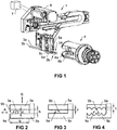
- the invention relates to a twisting device according to the preamble of claim 1, which comprises a feed device for feeding line ends of at least two lines and a rotatably mounted twisting head for twisting said lines.
- the feeder has first jaws for clamping the line ends
- the twisting head has second jaws for clamping the line ends.
- the feeding device and the twisting head are movable relative to each other into a transfer position, in which the first clamping jaws and the second clamping jaws face each other.
- the first clamping jaws are movable relative to one another in such a way that a distance between clamped line ends can be changed.
- the invention further relates to a method for twisting at least two lines by means of a twisting device comprising a feeding device with first clamping jaws and a twisting head with second clamping jaws, according to the preamble of claim 12.
- a twisting device of the type mentioned in addition comprises a controller which is connected to a drive for the first jaws and adapted for its control, such that the distance between clamped line ends is brought to an adjustable value prior to transfer to the twisting head , wherein this distance between the clamped line ends is selectable from at least two different values.
- the second clamping jaws have mutually facing clamping surfaces which are essentially flat or d) comprise more than two, in particular more than three, half-shell-shaped notches for receiving one line end each. What has been said about the first jaws applies mutatis mutandis.
- first clamping jaws in a clamping position are movable relative to each other such that a distance between two clamped line ends is variable. In this way, twisted pair cables can be made with differently spaced cable ends.
- first jaws and / or second jaws are slidably mounted to each other for clamping a line end.
- a precise clamping or precise compliance with a required distance of the line ends is possible.
- first clamping jaws are mounted so as to be rotatable relative to each other for changing the distance of clamped line ends without influencing a clamping position. This results in a simple structural design for the feeder.
- the distance between clamped line ends is brought by moving the first jaws in a clamping position before clamping the line ends in the second jaws of the twisting head to an adjustable value, this distance from at least two different values is selected.
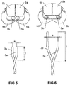
- the width b is at least 9 mm.
- the gap between the fully opened first jaws 5a, 5b is at least 9 mm in a direction of movement A for changing the position of the clamped line end 2a.
- Fig. 3 now shows an embodiment in which the clamping surfaces 9a, 9b are toothed.
- the tooth height z is advantageously less than 3% of the height h or less than 10% of the diameter d, as a result of which the clamping surfaces 9a, 9b are still essentially flat and the line 3a or the line end 2a can be clamped at any position between the clamps 5a, 5b , Because of the teeth is clamping against the in Fig. 2 However, shown embodiment more effective.
- An exemplary concrete twisting device is specified for twisting cables 3a, 3b having a cross section of 0.35 mm 2 to 2.5 mm 2 and can process cables with a diameter of up to 3 mm.
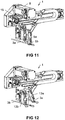
- the jaws have a width b of 9 mm, whereby the center distance of the lines 3a, 3b is a maximum of 15 mm (see also the distance a in the FIGS. 5 and 6 ).
- the tooth height z is 0.2 mm. Although these values are advantageous, they are not mandatory. If the twisting device can handle larger cables 3a, 3b, then the mass can be increased accordingly.
- Thin lines 3a, 3b can be arranged to each other at a smaller line spacing a than lines 3a, 3b with a large outer diameter, which are in particular equipped with large-volume (crimp) contacts and seals. In this way, the lines 3a, 3b can be twisted to the greatest possible length.
- first clamping jaws 5a..5d to be movable relative to one another in a clamping position such that a distance between three clamped line ends can be changed (see FIGS. 19 to 26 ). In this way, three-core twisted lines can be produced with differently spaced line ends.
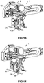
- Fig. 10 shows the feeding device 1 in a second state in which the first linear gripper 13a pivoted downward, the second linear gripper 13b is still pushed upwards and the jaws 5a..5d are still open.
- Fig. 12 shows the feeder 1 in a further state in which the first linear gripper 13a pivoted together with the clamped line 3a upwards, the second linear gripper 13b pushed down and the jaws 5c, 5d are still open. In the area of the clamping jaws 5c, 5d, the line 3b is already arranged.
- Fig. 13 shows the feeding device 1 in a further state in which the second linear gripper 13b has been positioned horizontally by means of the controller 7 and the drive 8 according to a required position of the line 3b.
- Fig. 14 shows the feeder 1 in a further state in which the jaws 5c, 5d have been closed and have clamped the line 3b.
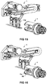
- Fig. 15 shows the feeding device 1 and the twisting head 4 in a state in which the first linear gripper 13a is pivoted downward and the lines 3a, 3b are arranged at a required distance from each other.
- Fig. 16 shows the feeder 1 and the twisting head 4 in a state in which the feeder 1 has been moved to a transfer position with the twisting head 4, in which the first jaws 5a..5d of the feeder 1 and the second jaws 6a, 6b of the twisting head 4 to each other stand opposite.
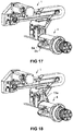
- Fig. 17 shows the feeding device 1 and the twisting head 4 in a state in which the second jaws 6a, 6b of the twisting head 4 have been closed and the lines 3a, 3b clamp.
- Fig. 18 shows the feeding device 1 and the twisting 4 in a state in which the first jaws 5a..5d of the feeder 1 are opened and the lines 3a, 3b were therefore passed to the twisting 4.
- the first linear gripper 13a is already pivoted upwards, so that the feeding device 1 can be moved away from the region of the twisting head 4.
- the lines 3a, 3b can be subsequently twisted in a conventional manner.
- the distance between clamped line ends 2a, 2b is brought by moving the first jaws 5a..5d in a clamping position before clamping the line ends 2a, 2b in the second jaws 6a, 6b of the twisting 4 to an adjustable value.
- at least two different values can be selected for the distance between the clamped line ends 2a, 2b.
- the line ends 2a, 2b are detected by the feeder 1 individually one after the other and simultaneously by the twisting head 4 simultaneously and clamped.
- the line ends 2a, 2b are also detected and clamped together by the feeder 1 at the same time.
- a variable position of the first jaws 5a..5d before clamping the line ends 2a, 2b at a selected distance a corresponding between the line ends 2a, 2b set, and the first jaws 5a..5d are before clamping the line ends 2a, 2b in the second jaws 6a, 6b of the twisting 4 moves in a fixed predetermined position (see in particular the FIGS. 2 to 6 and the horizontal guide 15, with which the linear grippers 13a, 13b can be moved horizontally.
- the distance a desired in the twisting head 4 is determined already during clamping by the feeding device 1, in that the linear grippers 13 a, 13 b move into a corresponding (variable) position when detecting the lines 2 a, 2 b (see in particular FIG Fig. 10 and Fig. 13 ).
- the position of the linear gripper 13a, 13b in the transfer to the twisting 4, however, is fixed. That is, the linear grippers 13a, 13b are always moved to the same position for the transfer of the lines 2a, 2b in the twisting head.
- first jaws 5a..5d before the Terminals of the line ends 2a, 2b are moved to a fixed predetermined position and a variable position of the first jaws 5a..5d before clamping the line ends 2a, 2b in the second jaws 6a, 6b of the twisting 4 according to a selected distance a between the line ends 2a, 3b is set.
- first clamping jaws 5a..5d for clamping a line end 2a, 2b to each other displaceable and for changing the distance between the clamped line ends 2a, 2b without affecting a clamping position be rotatable to each other, as in the FIGS. 1 to 18 is shown.
- first jaws 5a..5d are slidably mounted relative to one another both for clamping a line end 2a, 2b and for changing the distance of clamped line ends 2a, 2b.
- the first jaws 5a..5d can be rotatably mounted to each other both for clamping a line end 2a, 2b and for changing the distance between clamped line ends 2a, 2b.
- first jaws 5a..5d for clamping a line end 2a, 2b are rotatable relative to each other and for changing the distance between clamped line ends 2a, 2b are mounted to each other displaced without affecting a clamping position.
- FIGS. 19 to 26 now schematically show an exemplary sequence for clamping (and twisting) of three lines 3a..3c.
- the first clamping jaws 5a..5f are in an initial position, and a first line 3a is located in the region of the feeding device 1
- Fig. 20 shows the arrangement in a state in which the jaws 5a, 5b have been moved up to the first line 3a and have detected or clamped.
Priority Applications (8)
| Application Number | Priority Date | Filing Date | Title |
|---|---|---|---|
| EP14190317.9A EP3012842B1 (de) | 2014-10-24 | 2014-10-24 | Verdrilleinrichtung mit einstellbarem Abstand der Leitungsenden |
| PT14190317T PT3012842T (pt) | 2014-10-24 | 2014-10-24 | Dispositivo de torção com distância ajustável entre as extremidades do cabo |
| SG10201508421QA SG10201508421QA (en) | 2014-10-24 | 2015-10-10 | A twist application device with an adjustable distance between the conductor ends |
| KR1020150145890A KR20160048662A (ko) | 2014-10-24 | 2015-10-20 | 도체단부 사이의 간격을 조절하는 트위스팅 장치 |
| JP2015209023A JP2016085974A (ja) | 2014-10-24 | 2015-10-23 | 導線端間の距離を調整可能な撚り合わせ装置 |
| CN201510696158.1A CN105552680B (zh) | 2014-10-24 | 2015-10-23 | 导线端部的间距可调节的扭绞装置 |
| US14/922,453 US10046380B2 (en) | 2014-10-24 | 2015-10-26 | Twist application device with an adjustable distance between the conductor ends |
| US15/405,378 US10052676B2 (en) | 2014-10-24 | 2017-01-13 | Twist application device with an adjustable distance between the conductor ends |
Applications Claiming Priority (1)
| Application Number | Priority Date | Filing Date | Title |
|---|---|---|---|
| EP14190317.9A EP3012842B1 (de) | 2014-10-24 | 2014-10-24 | Verdrilleinrichtung mit einstellbarem Abstand der Leitungsenden |
Publications (2)
| Publication Number | Publication Date |
|---|---|
| EP3012842A1 EP3012842A1 (de) | 2016-04-27 |
| EP3012842B1 true EP3012842B1 (de) | 2019-06-12 |
Family
ID=51865986
Family Applications (1)
| Application Number | Title | Priority Date | Filing Date |
|---|---|---|---|
| EP14190317.9A Not-in-force EP3012842B1 (de) | 2014-10-24 | 2014-10-24 | Verdrilleinrichtung mit einstellbarem Abstand der Leitungsenden |
Country Status (6)
| Country | Link |
|---|---|
| EP (1) | EP3012842B1 (ko) |
| JP (1) | JP2016085974A (ko) |
| KR (1) | KR20160048662A (ko) |
| CN (1) | CN105552680B (ko) |
| PT (1) | PT3012842T (ko) |
| SG (1) | SG10201508421QA (ko) |
Families Citing this family (4)
| Publication number | Priority date | Publication date | Assignee | Title |
|---|---|---|---|---|
| DE102016109155B3 (de) | 2016-05-18 | 2017-08-03 | Lisa Dräxlmaier GmbH | Verdrillanlage, Tandem-Verdrillanlage und Verfahren zum Bestücken eines Verdrillkopfs |
| SG11202002673PA (en) * | 2017-11-10 | 2020-04-29 | Schleuniger Holding Ag | Twisting appliance and twisting head device and method for twisting or stranding cables |
| CN108657872B (zh) * | 2018-04-02 | 2023-06-20 | 浙江一丁点工艺品有限公司 | 一种绒条循环送料装置 |
| CN108975053B (zh) * | 2018-06-21 | 2020-11-10 | 芜湖文青机械设备设计有限公司 | 一种线束绕线装置 |
Family Cites Families (10)
| Publication number | Priority date | Publication date | Assignee | Title |
|---|---|---|---|---|
| US3827465A (en) * | 1972-03-20 | 1974-08-06 | Gardner Denver Co | Apparatus for forming twisted pairs of conductor wire |
| US4341014A (en) * | 1980-05-07 | 1982-07-27 | Cooper Industries, Inc. | Method and apparatus for interconnecting pairs of terminals with a pretwisted pair of insulated wires |
| US5238177A (en) * | 1992-08-10 | 1993-08-24 | Flexible Steel Lacing Company | Method and apparatus for forming conveyor belt hinge pins |
| DE59914354D1 (de) * | 1998-08-31 | 2007-07-12 | Komax Holding Ag | Einrichtung zum Zusammenführen von Leitern |
| EP0984530B1 (de) * | 1998-08-31 | 2007-05-30 | komax Holding AG | Einrichtung zum Zusammenführen von Leitern |
| EP1032095B1 (de) | 1999-02-23 | 2013-05-22 | Komax Holding AG | Verfahren und Einrichtung zur Bearbeitung und Verdrillung eines Leiterpaares |
| US6289944B1 (en) * | 1999-02-23 | 2001-09-18 | Komax Holding Ag | Method and equipment for the treatment and twisting together of a conductor pair |
| JP2003217371A (ja) * | 2002-01-23 | 2003-07-31 | Auto Network Gijutsu Kenkyusho:Kk | ツイストペア電線の製造方法とその装置 |
| WO2013068990A1 (de) * | 2011-11-11 | 2013-05-16 | Schleuniger Holding Ag | Verdrillvorrichtung |
| JP6282929B2 (ja) * | 2014-05-16 | 2018-02-21 | 日本オートマチックマシン株式会社 | 電線撚り合わせ装置、ツイストケーブル製造装置、電線撚り合わせ方法、及びツイストケーブル製造方法 |
-
2014
- 2014-10-24 PT PT14190317T patent/PT3012842T/pt unknown
- 2014-10-24 EP EP14190317.9A patent/EP3012842B1/de not_active Not-in-force
-
2015
- 2015-10-10 SG SG10201508421QA patent/SG10201508421QA/en unknown
- 2015-10-20 KR KR1020150145890A patent/KR20160048662A/ko unknown
- 2015-10-23 CN CN201510696158.1A patent/CN105552680B/zh not_active Expired - Fee Related
- 2015-10-23 JP JP2015209023A patent/JP2016085974A/ja not_active Ceased
Non-Patent Citations (1)
| Title |
|---|
| None * |
Also Published As
| Publication number | Publication date |
|---|---|
| CN105552680A (zh) | 2016-05-04 |
| EP3012842A1 (de) | 2016-04-27 |
| KR20160048662A (ko) | 2016-05-04 |
| SG10201508421QA (en) | 2016-05-30 |
| JP2016085974A (ja) | 2016-05-19 |
| CN105552680B (zh) | 2020-04-24 |
| PT3012842T (pt) | 2019-09-10 |
Similar Documents
| Publication | Publication Date | Title |
|---|---|---|
| EP3012841A1 (de) | Einrichtung zum Zuführen von Leitungsenden an eine weiterverarbeitende Vorrichtung | |
| EP3301768B1 (de) | Verfahren und vorrichtung zum rotationslagerichtigen ausrichten von konfektionierten kabelenden eines kabelstrangs | |
| EP3104471B1 (de) | Kabelbearbeitungseinrichtung zur bearbeitung von kabeladern eines mehradrigen kabels | |
| EP3301769B1 (de) | Vorrichtung und verfahren zum bestücken eines steckergehäuses mit konfektionierten kabelenden eines kabelstrangs | |
| EP3012842B1 (de) | Verdrilleinrichtung mit einstellbarem Abstand der Leitungsenden | |
| EP0161400A1 (de) | Zahntechnisches Verfahren und Vorrichtung zum Biegen und Tordieren eines Drahtstückes | |
| EP3052256B1 (de) | Biegepresse und biegeverfahren | |
| EP2289643B1 (de) | Vorrichtung zum Biegen länglicher Werkstücke | |
| EP2897770B1 (de) | Zwillingsgreifer | |
| EP3557592B1 (de) | Vorrichtung und verfahren zum verdrillen einer ersten und zweiten elektrischen einzelleitung zu einem leitungspaar | |
| CH684374A5 (de) | Kabelzuführungs- und -wechseleinrichtung für eine Kabelverarbeitungsmaschine. | |
| DE202009004913U1 (de) | Vorrichtung zum Verdrillen von Leitungen | |
| CH712087B1 (de) | Zentriereinheit, Crimpvorrichtung und Kabelbearbeitungsanlage. | |
| DE102010017981B4 (de) | Einrichtung und Verfahren zum Zusammenführen von Leitern | |
| EP3614821A1 (de) | Verdrahtungsroboter und verfahren zum verdrahten, system und verfahren zum planen von verdrahtungen, system und verfahren zum erfassen von bauteilen | |
| DE202010001324U1 (de) | Vorrichtung zum Verdrillen von Leitungen | |
| EP3804048B1 (de) | Vorrichtung und verfahren zum bearbeiten eines endes eines elektrischen kabels | |
| EP3652817B1 (de) | Drahthandlingvorrichtung | |
| DE202016009044U1 (de) | Fertigungsanlage zur Fertigung von Werkstücken aus Blech | |
| EP2779327B1 (de) | Kabeldrehzange und Verfahren für Zuführung eines elektrischen Leiters | |
| DE102016109155B3 (de) | Verdrillanlage, Tandem-Verdrillanlage und Verfahren zum Bestücken eines Verdrillkopfs | |
| DE102012213391A1 (de) | Vorrichtung und Verfahren zum Verdrillen und Ausrichten eines nicht verdrillten Endes eines teilweise verdrillten Kabels | |
| EP0844704A2 (de) | Verfahren zum Herstellen von verdrillten, konfektionierten leitungen sowie Vorrichtung zum Durchführen des Verfahrens | |
| DE3315336A1 (de) | Kombinierte vorrichtung zum programmierten abschneiden | |
| DE19735655C2 (de) | Verfahren zum Herstellen von verdrillten, konfektionierten Leitungen sowie Vorrichtung zum Durchführen des Verfahrens |
Legal Events
| Date | Code | Title | Description |
|---|---|---|---|
| PUAI | Public reference made under article 153(3) epc to a published international application that has entered the european phase |
Free format text: ORIGINAL CODE: 0009012 |
|
| AK | Designated contracting states |
Kind code of ref document: A1 Designated state(s): AL AT BE BG CH CY CZ DE DK EE ES FI FR GB GR HR HU IE IS IT LI LT LU LV MC MK MT NL NO PL PT RO RS SE SI SK SM TR |
|
| AX | Request for extension of the european patent |
Extension state: BA ME |
|
| STAA | Information on the status of an ep patent application or granted ep patent |
Free format text: STATUS: REQUEST FOR EXAMINATION WAS MADE |
|
| 17P | Request for examination filed |
Effective date: 20161027 |
|
| RBV | Designated contracting states (corrected) |
Designated state(s): AL AT BE BG CH CY CZ DE DK EE ES FI FR GB GR HR HU IE IS IT LI LT LU LV MC MK MT NL NO PL PT RO RS SE SI SK SM TR |
|
| GRAP | Despatch of communication of intention to grant a patent |
Free format text: ORIGINAL CODE: EPIDOSNIGR1 |
|
| STAA | Information on the status of an ep patent application or granted ep patent |
Free format text: STATUS: GRANT OF PATENT IS INTENDED |
|
| RIC1 | Information provided on ipc code assigned before grant |
Ipc: H01B 13/00 20060101ALN20190215BHEP Ipc: H01B 13/02 20060101AFI20190215BHEP Ipc: B65H 51/18 20060101ALI20190215BHEP |
|
| INTG | Intention to grant announced |
Effective date: 20190307 |
|
| GRAS | Grant fee paid |
Free format text: ORIGINAL CODE: EPIDOSNIGR3 |
|
| GRAA | (expected) grant |
Free format text: ORIGINAL CODE: 0009210 |
|
| STAA | Information on the status of an ep patent application or granted ep patent |
Free format text: STATUS: THE PATENT HAS BEEN GRANTED |
|
| AK | Designated contracting states |
Kind code of ref document: B1 Designated state(s): AL AT BE BG CH CY CZ DE DK EE ES FI FR GB GR HR HU IE IS IT LI LT LU LV MC MK MT NL NO PL PT RO RS SE SI SK SM TR |
|
| REG | Reference to a national code |
Ref country code: GB Ref legal event code: FG4D Free format text: NOT ENGLISH |
|
| REG | Reference to a national code |
Ref country code: CH Ref legal event code: EP |
|
| REG | Reference to a national code |
Ref country code: AT Ref legal event code: REF Ref document number: 1143639 Country of ref document: AT Kind code of ref document: T Effective date: 20190615 |
|
| REG | Reference to a national code |
Ref country code: DE Ref legal event code: R096 Ref document number: 502014011907 Country of ref document: DE |
|
| REG | Reference to a national code |
Ref country code: IE Ref legal event code: FG4D Free format text: LANGUAGE OF EP DOCUMENT: GERMAN |
|
| REG | Reference to a national code |
Ref country code: CH Ref legal event code: NV Representative=s name: ROSENICH PAUL; KUENSCH JOACHIM PATENTBUERO PAU, LI |
|
| REG | Reference to a national code |
Ref country code: PT Ref legal event code: SC4A Ref document number: 3012842 Country of ref document: PT Date of ref document: 20190910 Kind code of ref document: T Free format text: AVAILABILITY OF NATIONAL TRANSLATION Effective date: 20190820 |
|
| REG | Reference to a national code |
Ref country code: NL Ref legal event code: MP Effective date: 20190612 |
|
| REG | Reference to a national code |
Ref country code: LT Ref legal event code: MG4D |
|
| PG25 | Lapsed in a contracting state [announced via postgrant information from national office to epo] |
Ref country code: FI Free format text: LAPSE BECAUSE OF FAILURE TO SUBMIT A TRANSLATION OF THE DESCRIPTION OR TO PAY THE FEE WITHIN THE PRESCRIBED TIME-LIMIT Effective date: 20190612 Ref country code: NO Free format text: LAPSE BECAUSE OF FAILURE TO SUBMIT A TRANSLATION OF THE DESCRIPTION OR TO PAY THE FEE WITHIN THE PRESCRIBED TIME-LIMIT Effective date: 20190912 Ref country code: HR Free format text: LAPSE BECAUSE OF FAILURE TO SUBMIT A TRANSLATION OF THE DESCRIPTION OR TO PAY THE FEE WITHIN THE PRESCRIBED TIME-LIMIT Effective date: 20190612 Ref country code: SE Free format text: LAPSE BECAUSE OF FAILURE TO SUBMIT A TRANSLATION OF THE DESCRIPTION OR TO PAY THE FEE WITHIN THE PRESCRIBED TIME-LIMIT Effective date: 20190612 Ref country code: AL Free format text: LAPSE BECAUSE OF FAILURE TO SUBMIT A TRANSLATION OF THE DESCRIPTION OR TO PAY THE FEE WITHIN THE PRESCRIBED TIME-LIMIT Effective date: 20190612 Ref country code: LT Free format text: LAPSE BECAUSE OF FAILURE TO SUBMIT A TRANSLATION OF THE DESCRIPTION OR TO PAY THE FEE WITHIN THE PRESCRIBED TIME-LIMIT Effective date: 20190612 |
|
| PGFP | Annual fee paid to national office [announced via postgrant information from national office to epo] |
Ref country code: PT Payment date: 20190925 Year of fee payment: 6 |
|
| PG25 | Lapsed in a contracting state [announced via postgrant information from national office to epo] |
Ref country code: BG Free format text: LAPSE BECAUSE OF FAILURE TO SUBMIT A TRANSLATION OF THE DESCRIPTION OR TO PAY THE FEE WITHIN THE PRESCRIBED TIME-LIMIT Effective date: 20190912 Ref country code: RS Free format text: LAPSE BECAUSE OF FAILURE TO SUBMIT A TRANSLATION OF THE DESCRIPTION OR TO PAY THE FEE WITHIN THE PRESCRIBED TIME-LIMIT Effective date: 20190612 Ref country code: LV Free format text: LAPSE BECAUSE OF FAILURE TO SUBMIT A TRANSLATION OF THE DESCRIPTION OR TO PAY THE FEE WITHIN THE PRESCRIBED TIME-LIMIT Effective date: 20190612 Ref country code: GR Free format text: LAPSE BECAUSE OF FAILURE TO SUBMIT A TRANSLATION OF THE DESCRIPTION OR TO PAY THE FEE WITHIN THE PRESCRIBED TIME-LIMIT Effective date: 20190913 |
|
| PG25 | Lapsed in a contracting state [announced via postgrant information from national office to epo] |
Ref country code: RO Free format text: LAPSE BECAUSE OF FAILURE TO SUBMIT A TRANSLATION OF THE DESCRIPTION OR TO PAY THE FEE WITHIN THE PRESCRIBED TIME-LIMIT Effective date: 20190612 Ref country code: CZ Free format text: LAPSE BECAUSE OF FAILURE TO SUBMIT A TRANSLATION OF THE DESCRIPTION OR TO PAY THE FEE WITHIN THE PRESCRIBED TIME-LIMIT Effective date: 20190612 Ref country code: SK Free format text: LAPSE BECAUSE OF FAILURE TO SUBMIT A TRANSLATION OF THE DESCRIPTION OR TO PAY THE FEE WITHIN THE PRESCRIBED TIME-LIMIT Effective date: 20190612 Ref country code: EE Free format text: LAPSE BECAUSE OF FAILURE TO SUBMIT A TRANSLATION OF THE DESCRIPTION OR TO PAY THE FEE WITHIN THE PRESCRIBED TIME-LIMIT Effective date: 20190612 Ref country code: NL Free format text: LAPSE BECAUSE OF FAILURE TO SUBMIT A TRANSLATION OF THE DESCRIPTION OR TO PAY THE FEE WITHIN THE PRESCRIBED TIME-LIMIT Effective date: 20190612 |
|
| PGFP | Annual fee paid to national office [announced via postgrant information from national office to epo] |
Ref country code: DE Payment date: 20191031 Year of fee payment: 6 Ref country code: CH Payment date: 20190911 Year of fee payment: 6 |
|
| PG25 | Lapsed in a contracting state [announced via postgrant information from national office to epo] |
Ref country code: SM Free format text: LAPSE BECAUSE OF FAILURE TO SUBMIT A TRANSLATION OF THE DESCRIPTION OR TO PAY THE FEE WITHIN THE PRESCRIBED TIME-LIMIT Effective date: 20190612 Ref country code: ES Free format text: LAPSE BECAUSE OF FAILURE TO SUBMIT A TRANSLATION OF THE DESCRIPTION OR TO PAY THE FEE WITHIN THE PRESCRIBED TIME-LIMIT Effective date: 20190612 Ref country code: IS Free format text: LAPSE BECAUSE OF FAILURE TO SUBMIT A TRANSLATION OF THE DESCRIPTION OR TO PAY THE FEE WITHIN THE PRESCRIBED TIME-LIMIT Effective date: 20191012 |
|
| PGFP | Annual fee paid to national office [announced via postgrant information from national office to epo] |
Ref country code: IT Payment date: 20191031 Year of fee payment: 6 |
|
| REG | Reference to a national code |
Ref country code: DE Ref legal event code: R097 Ref document number: 502014011907 Country of ref document: DE |
|
| PG25 | Lapsed in a contracting state [announced via postgrant information from national office to epo] |
Ref country code: TR Free format text: LAPSE BECAUSE OF FAILURE TO SUBMIT A TRANSLATION OF THE DESCRIPTION OR TO PAY THE FEE WITHIN THE PRESCRIBED TIME-LIMIT Effective date: 20190612 |
|
| PLBE | No opposition filed within time limit |
Free format text: ORIGINAL CODE: 0009261 |
|
| STAA | Information on the status of an ep patent application or granted ep patent |
Free format text: STATUS: NO OPPOSITION FILED WITHIN TIME LIMIT |
|
| PG25 | Lapsed in a contracting state [announced via postgrant information from national office to epo] |
Ref country code: PL Free format text: LAPSE BECAUSE OF FAILURE TO SUBMIT A TRANSLATION OF THE DESCRIPTION OR TO PAY THE FEE WITHIN THE PRESCRIBED TIME-LIMIT Effective date: 20190612 Ref country code: DK Free format text: LAPSE BECAUSE OF FAILURE TO SUBMIT A TRANSLATION OF THE DESCRIPTION OR TO PAY THE FEE WITHIN THE PRESCRIBED TIME-LIMIT Effective date: 20190612 |
|
| 26N | No opposition filed |
Effective date: 20200313 |
|
| PG25 | Lapsed in a contracting state [announced via postgrant information from national office to epo] |
Ref country code: IS Free format text: LAPSE BECAUSE OF FAILURE TO SUBMIT A TRANSLATION OF THE DESCRIPTION OR TO PAY THE FEE WITHIN THE PRESCRIBED TIME-LIMIT Effective date: 20200224 Ref country code: SI Free format text: LAPSE BECAUSE OF FAILURE TO SUBMIT A TRANSLATION OF THE DESCRIPTION OR TO PAY THE FEE WITHIN THE PRESCRIBED TIME-LIMIT Effective date: 20190612 Ref country code: MC Free format text: LAPSE BECAUSE OF FAILURE TO SUBMIT A TRANSLATION OF THE DESCRIPTION OR TO PAY THE FEE WITHIN THE PRESCRIBED TIME-LIMIT Effective date: 20190612 |
|
| PG2D | Information on lapse in contracting state deleted |
Ref country code: IS |
|
| PG25 | Lapsed in a contracting state [announced via postgrant information from national office to epo] |
Ref country code: LU Free format text: LAPSE BECAUSE OF NON-PAYMENT OF DUE FEES Effective date: 20191024 |
|
| REG | Reference to a national code |
Ref country code: BE Ref legal event code: MM Effective date: 20191031 |
|
| PG25 | Lapsed in a contracting state [announced via postgrant information from national office to epo] |
Ref country code: BE Free format text: LAPSE BECAUSE OF NON-PAYMENT OF DUE FEES Effective date: 20191031 |
|
| GBPC | Gb: european patent ceased through non-payment of renewal fee |
Effective date: 20191024 |
|
| REG | Reference to a national code |
Ref country code: CH Ref legal event code: PCAR Free format text: NEW ADDRESS: ROTENBODENSTRASSE 12, 9497 TRIESENBERG (LI) |
|
| PG25 | Lapsed in a contracting state [announced via postgrant information from national office to epo] |
Ref country code: FR Free format text: LAPSE BECAUSE OF NON-PAYMENT OF DUE FEES Effective date: 20191031 Ref country code: GB Free format text: LAPSE BECAUSE OF NON-PAYMENT OF DUE FEES Effective date: 20191024 Ref country code: IE Free format text: LAPSE BECAUSE OF NON-PAYMENT OF DUE FEES Effective date: 20191024 |
|
| REG | Reference to a national code |
Ref country code: AT Ref legal event code: MM01 Ref document number: 1143639 Country of ref document: AT Kind code of ref document: T Effective date: 20191024 |
|
| PG25 | Lapsed in a contracting state [announced via postgrant information from national office to epo] |
Ref country code: AT Free format text: LAPSE BECAUSE OF NON-PAYMENT OF DUE FEES Effective date: 20191024 |
|
| REG | Reference to a national code |
Ref country code: DE Ref legal event code: R119 Ref document number: 502014011907 Country of ref document: DE |
|
| PG25 | Lapsed in a contracting state [announced via postgrant information from national office to epo] |
Ref country code: CY Free format text: LAPSE BECAUSE OF FAILURE TO SUBMIT A TRANSLATION OF THE DESCRIPTION OR TO PAY THE FEE WITHIN THE PRESCRIBED TIME-LIMIT Effective date: 20190612 |
|
| REG | Reference to a national code |
Ref country code: CH Ref legal event code: PL |
|
| PG25 | Lapsed in a contracting state [announced via postgrant information from national office to epo] |
Ref country code: PT Free format text: LAPSE BECAUSE OF NON-PAYMENT OF DUE FEES Effective date: 20210426 Ref country code: MT Free format text: LAPSE BECAUSE OF FAILURE TO SUBMIT A TRANSLATION OF THE DESCRIPTION OR TO PAY THE FEE WITHIN THE PRESCRIBED TIME-LIMIT Effective date: 20190612 Ref country code: HU Free format text: LAPSE BECAUSE OF FAILURE TO SUBMIT A TRANSLATION OF THE DESCRIPTION OR TO PAY THE FEE WITHIN THE PRESCRIBED TIME-LIMIT; INVALID AB INITIO Effective date: 20141024 Ref country code: DE Free format text: LAPSE BECAUSE OF NON-PAYMENT OF DUE FEES Effective date: 20210501 |
|
| PG25 | Lapsed in a contracting state [announced via postgrant information from national office to epo] |
Ref country code: LI Free format text: LAPSE BECAUSE OF NON-PAYMENT OF DUE FEES Effective date: 20201031 Ref country code: CH Free format text: LAPSE BECAUSE OF NON-PAYMENT OF DUE FEES Effective date: 20201031 |
|
| PG25 | Lapsed in a contracting state [announced via postgrant information from national office to epo] |
Ref country code: IT Free format text: LAPSE BECAUSE OF NON-PAYMENT OF DUE FEES Effective date: 20201024 |
|
| PG25 | Lapsed in a contracting state [announced via postgrant information from national office to epo] |
Ref country code: MK Free format text: LAPSE BECAUSE OF FAILURE TO SUBMIT A TRANSLATION OF THE DESCRIPTION OR TO PAY THE FEE WITHIN THE PRESCRIBED TIME-LIMIT Effective date: 20190612 |