EP3012842B1 - Twisting device with an adjustable distance between the cable ends - Google Patents
Twisting device with an adjustable distance between the cable ends Download PDFInfo
- Publication number
- EP3012842B1 EP3012842B1 EP14190317.9A EP14190317A EP3012842B1 EP 3012842 B1 EP3012842 B1 EP 3012842B1 EP 14190317 A EP14190317 A EP 14190317A EP 3012842 B1 EP3012842 B1 EP 3012842B1
- Authority
- EP
- European Patent Office
- Prior art keywords
- clamping
- jaws
- twisting
- clamping jaws
- conductor ends
- Prior art date
- Legal status (The legal status is an assumption and is not a legal conclusion. Google has not performed a legal analysis and makes no representation as to the accuracy of the status listed.)
- Not-in-force
Links
Images


Classifications
-
- H—ELECTRICITY
- H01—ELECTRIC ELEMENTS
- H01B—CABLES; CONDUCTORS; INSULATORS; SELECTION OF MATERIALS FOR THEIR CONDUCTIVE, INSULATING OR DIELECTRIC PROPERTIES
- H01B13/00—Apparatus or processes specially adapted for manufacturing conductors or cables
- H01B13/02—Stranding-up
- H01B13/0207—Details; Auxiliary devices
-
- H—ELECTRICITY
- H01—ELECTRIC ELEMENTS
- H01R—ELECTRICALLY-CONDUCTIVE CONNECTIONS; STRUCTURAL ASSOCIATIONS OF A PLURALITY OF MUTUALLY-INSULATED ELECTRICAL CONNECTING ELEMENTS; COUPLING DEVICES; CURRENT COLLECTORS
- H01R43/00—Apparatus or processes specially adapted for manufacturing, assembling, maintaining, or repairing of line connectors or current collectors or for joining electric conductors
- H01R43/033—Apparatus or processes specially adapted for manufacturing, assembling, maintaining, or repairing of line connectors or current collectors or for joining electric conductors for wrapping or unwrapping wire connections
-
- B—PERFORMING OPERATIONS; TRANSPORTING
- B65—CONVEYING; PACKING; STORING; HANDLING THIN OR FILAMENTARY MATERIAL
- B65H—HANDLING THIN OR FILAMENTARY MATERIAL, e.g. SHEETS, WEBS, CABLES
- B65H51/00—Forwarding filamentary material
- B65H51/18—Gripping devices with linear motion
-
- H—ELECTRICITY
- H01—ELECTRIC ELEMENTS
- H01B—CABLES; CONDUCTORS; INSULATORS; SELECTION OF MATERIALS FOR THEIR CONDUCTIVE, INSULATING OR DIELECTRIC PROPERTIES
- H01B13/00—Apparatus or processes specially adapted for manufacturing conductors or cables
- H01B13/0003—Apparatus or processes specially adapted for manufacturing conductors or cables for feeding conductors or cables
Landscapes
- Engineering & Computer Science (AREA)
- Manufacturing & Machinery (AREA)
- Processes Specially Adapted For Manufacturing Cables (AREA)
- Wire Processing (AREA)
Description
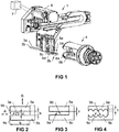
Die Erfindung betrifft eine Verdrilleinrichtung gemäss dem Oberbegriff des Anspruchs 1, welche eine Zuführvorrichtung zum Zuführen von Leitungsenden zumindest zweier Leitungen und einen drehbar gelagerten Verdrillkopf zum Verdrillen der besagten Leitungen umfasst.The invention relates to a twisting device according to the preamble of
Die Zuführvorrichtung weist erste Klemmbacken zum Klemmen der Leitungsenden, und der Verdrillkopf weist zweite Klemmbacken zum Klemmen der Leitungsenden auf. Die Zuführeinrichtung und der Verdrillkopf sind zueinander in eine Übergabestellung bewegbar, in der die ersten Klemmbacken und die zweiten Klemmbacken einander gegenüber stehen. Die ersten Klemmbacken sind in einer Klemmstellung darüber hinaus derart gegeneinander bewegbar, dass ein Abstand geklemmter Leitungsenden veränderbar ist.The feeder has first jaws for clamping the line ends, and the twisting head has second jaws for clamping the line ends. The feeding device and the twisting head are movable relative to each other into a transfer position, in which the first clamping jaws and the second clamping jaws face each other. In addition, in a clamping position, the first clamping jaws are movable relative to one another in such a way that a distance between clamped line ends can be changed.
Die Erfindung betrifft weiterhin ein Verfahren zum Verdrillen von zumindest zwei Leitungen mit Hilfe einer Verdrilleinrichtung umfassend eine Zuführvorrichtung mit ersten Klemmbacken und einem Verdrillkopf mit zweiten Klemmbacken, gemäss dem Oberbegriff des Anspruchs 12.The invention further relates to a method for twisting at least two lines by means of a twisting device comprising a feeding device with first clamping jaws and a twisting head with second clamping jaws, according to the preamble of claim 12.
Dabei werden Leitungsenden der besagten Leitungen zwischen den ersten Klemmbacken der Zuführvorrichtung geklemmt und die Zuführeinrichtung in eine Übergabestellung mit dem Verdrillkopf bewegt, in der die ersten Klemmbacken der Zuführvorrichtung und die zweiten Klemmbacken des Verdrillkopfs einander gegenüber stehen. Dann werden die Leitungsenden zwischen den zweiten Klemmbacken des Verdrillkopfs geklemmt, die ersten Klemmbacken der Zuführvorrichtung gelöst und die besagten Leitungen durch Drehen des Verdrillkopfs verdrillt.In this case, line ends of said lines are clamped between the first jaws of the feeder and the feeder moved to a transfer position with the twisting head in which the first jaws of the feeder and the second jaws of the twisting head face each other. Then the lead ends are clamped between the second jaws of the twisting head, the first Loosened jaws of the feeder and twisted said lines by turning the twisting head.
Eine Verdrilleinrichtung sowie ein Verfahren zum Verdrillen von zwei Leitungen der oben genannten Art sind aus dem Stand der Technik grundsätzlich bekannt. Die
Generell wird angestrebt, Leitungen auf möglichst der gesamten Länge zu verdrillen. Der Abstand der Leitungsenden beim Verdrillen hat großen Einfluss darauf, welche kürzeste Länge für den unverdrillten Endabschnitt erreicht werden kann. Je größer der Abstand der Leitungsenden ist, umso länger ist auch der in der Regel unerwünschte unverdrillte Endabschnitt. Der Abstand zwischen den Leitungsenden kann jedoch nicht beliebig verkleinert werden, insbesondere weil auch Leitungsenden mit montierten Dichtungen und/oder Kontakten verarbeitet werden.In general, it is desirable to twist lines as far as possible over the entire length. The distance of the cable ends during twisting has a great influence on which shortest length can be achieved for the untwisted end section. The greater the distance of the line ends, the longer is the usually unwanted untwisted end section. However, the distance between the line ends can not be arbitrarily reduced, especially because line ends are processed with mounted seals and / or contacts.
Nach dem Stand der Technik sind Zuführvorrichtung und der Verdrillkopf daher konstruktiv auf den größten vorkommenden Abstand der Leitungsenden ausgelegt, wodurch der unverdrillte Endabschnitt nur dann so kurz als möglich ist, wenn die Leitungsenden - etwa aufgrund montierter Dichtungen und Kontakte - nicht in geringerem Abstand als im Verdrillkopf anordenbar sind. Alle anderen verdrillten Leitungen, und dies stellt die Mehrheit dar, weisen demzufolge einen an sich zu langen unverdrillten Endabschnitt auf.In the prior art supply device and the twisting head are therefore designed to the largest occurring distance of the line ends, whereby the untwisted end portion is only as short as possible when the line ends - for example due to mounted seals and contacts - not at a closer distance than in Twisting head can be arranged. All other twisted wires, and this represents the majority, thus have a long untwisted end portion.
Die
Eine Aufgabe der vorliegenden Erfindung ist es daher, eine verbesserte Verdrilleinrichtung und ein verbessertes Verfahren zum Verdrillen von Leitungen anzugeben. Insbesondere soll der unverdrillte Endabschnitt so kurz als möglich sein.It is therefore an object of the present invention to provide an improved twisting device and method for twisting wires. In particular, the untwisted end section should be as short as possible.
Die Aufgabe wird durch die Merkmale der unabhängigen Ansprüche 1 und 12 gelöst. Vorteilhafte Weiterbildungen sind in den Figuren und in den abhängigen Patentansprüchen dargelegt.The object is solved by the features of
Gemäss der Erfindung umfasst eine Verdrilleinrichtung der eingangs genannten Art zusätzlich eine Steuerung, welche mit einem Antrieb für die ersten Klemmbacken verbunden und für dessen Ansteuerung eingerichtet ist, derart, dass der Abstand zwischen geklemmten Leitungsenden vor der Übergabe in den Verdrillkopf auf einen einstellbaren Wert gebracht wird, wobei dieser Abstand zwischen den geklemmten Leitungsenden aus wenigstens zwei unterschiedlichen Werte auswählbar ist.According to the invention, a twisting device of the type mentioned in addition comprises a controller which is connected to a drive for the first jaws and adapted for its control, such that the distance between clamped line ends is brought to an adjustable value prior to transfer to the twisting head , wherein this distance between the clamped line ends is selectable from at least two different values.
Gemäss der Erfindung wird der Abstand zwischen geklemmten Leitungsenden bei einem Verfahren der eingangs genannten Art durch Bewegen der ersten Klemmbacken in einer Klemmstellung vor dem Klemmen der Leitungsenden in den zweiten Klemmbacken des Verdrillkopfs auf einen einstellbaren Wert gebracht. Denkbar ist es aber auch, dass die Leitungsenden vermessen werden (z.B. optisch) und ein (minimaler) Abstand automatisch eingestellt wird.According to the invention, the distance between clamped line ends in a method of the type mentioned by bringing the first jaws in a clamping position before clamping the line ends in the second jaws of the twisting head is brought to an adjustable value. It is also conceivable, however, that the line ends are measured (eg optically) and a (minimum) distance is set automatically.
Die Konstruktion der Verdrilleinrichtung und die Funktionsabläufe in derselben ermöglichen es, die Leitungsenden im einem variablen Abstand zueinander zu verdrillen. Dünne Leitungen, gegebenenfalls mit kleinen (Crimp)Kontakten und kleinen Dichtungen, können zueinander in einem kleineren Leitungsabstand angeordnet werden als Leitungen mit großem Aussendurchmesser, welche insbesondere mit großvolumigen (Crimp)Kontakten und Dichtungen bestückt sind. Auf diese Weise können die Leitungen auf größtmöglicher Länge verdrillt werden, beziehungsweise können die nicht verdrillten Leitungsenden möglichst kurz bleiben. Zudem können ein geforderter Leitungsabstand sowie eine geforderte unverdrillte Leitungslänge gut eingehalten werden.The construction of the twisting device and the functional processes in the same make it possible to twist the cable ends at a variable distance from each other. Thin lines, possibly with small (crimp) contacts and small seals, can be arranged to each other in a smaller line spacing than lines with a large outer diameter, which are particularly equipped with large-volume (crimp) contacts and seals. In this way, the lines can be twisted to the greatest possible length, or the non-twisted cable ends can remain as short as possible. In addition, a required line spacing and a required untwisted line length can be well maintained.
Weitere vorteilhafte Ausgestaltungen und Weiterbildungen der Erfindung ergeben sich aus den Unteransprüchen sowie aus der Beschreibung in Zusammenschau mit den Figuren.Further advantageous embodiments and modifications of the invention will become apparent from the dependent claims and from the description in conjunction with the figures.
Vorteilhaft ist es, wenn sich ein bei vollständig geöffneten ersten Klemmbacken zwischen diesen liegender Zwischenraum in einer Bewegungsrichtung zum Verändern des Abstands geklemmter Leitungsenden zumindest zweimal so weit erstreckt wie in einer Klemmrichtung der ersten Klemmbacken zum Klemmen der Leitungsenden. Insbesondere kann der genannte Zwischenraum in einer Bewegungsrichtung zum Verändern des Abstands geklemmter Leitungsenden zumindest zweimal so groß sein wie ein Durchmesser der Leitungsenden, für welche die Zuführvorrichtung spezifiziert ist. Von Vorteil ist es schließlich auch, wenn der genannte Zwischenraum in einer Bewegungsrichtung zum Verändern des Abstands geklemmter Leitungsenden zumindest 9 mm groß ist. Auf diese Weise können die Leitungsenden von der Zuführvorrichtung in den ersten Klemmen in unterschiedlicher Position und somit in unterschiedlichem Abstand zueinander geklemmt werden.It is advantageous if a lying at fully open first jaws between these intermediate space in a direction of movement for changing the distance of clamped line ends at least twice as far as in a clamping direction of the first jaws for clamping the line ends. In particular, said clearance in a moving direction for changing the distance of clamped pipe ends may be at least twice as large as a diameter of the pipe ends for which the feeding device is specified. Finally, it is also advantageous if the said intermediate space is at least 9 mm in a direction of movement for changing the distance of clamped cable ends. In this way, the line ends of the feeder in the first terminals in different Position and thus be clamped at different distances from each other.
Besonders vorteilhaft ist es, wenn die ersten Klemmbacken einander zugewandte Klemmflächen aufweisen, die a) im Wesentlichen flach sind oder b) mehr als eine, insbesondere mehr als zwei, halbschalenförmige Einkerbungen zur Aufnahme je eines Leitungsendes umfassen. Der Fall a) ermöglicht das Klemmen in beliebiger Position. Die ersten Klemmen können für einen sicheren Halt auch gezahnt sein, wobei die Zahnhöhe vorteilhaft kleiner als 10% des Leitungsdurchmessers ist und/oder kleiner als 3% des Abstands der ersten Klemmbacken in Klemmrichtung bei vollständig geöffneten ersten Klemmbacken und/oder kleiner als 0,3 mm. Die Klemmflächen sind dann noch im Wesentlichen flach. Der Fall b) ermöglicht das Klemmen der Leitungsenden schliesslich an mehreren vorgegeben Positionen.It is particularly advantageous if the first clamping jaws have mutually facing clamping surfaces which are a) substantially flat or b) comprise more than one, in particular more than two, half-shell-shaped indentations for receiving one line end each. Case a) allows clamping in any position. The first clamps may also be toothed for a secure fit, the tooth height advantageously being less than 10% of the pipe diameter and / or less than 3% of the distance of the first clamping jaws in the clamping direction with the first jaws fully open and / or less than 0.3 mm. The clamping surfaces are then still substantially flat. The case b) allows the terminals of the line ends finally at several predetermined positions.
Besonders vorteilhaft ist es auch, wenn die zweiten Klemmbacken einander zugewandte Klemmflächen aufweisen, die c) im Wesentlichen flach sind oder d) mehr als zwei, insbesondere mehr als drei, halbschalenförmige Einkerbungen zur Aufnahme je eines Leitungsendes umfassen. Das zu den ersten Klemmbacken Gesagte gilt hier sinngemäß.It is also particularly advantageous if the second clamping jaws have mutually facing clamping surfaces which are essentially flat or d) comprise more than two, in particular more than three, half-shell-shaped notches for receiving one line end each. What has been said about the first jaws applies mutatis mutandis.
Günstig ist es zudem, wenn die ersten Klemmbacken in einer Klemmstellung derart gegeneinander bewegbar sind, dass ein Abstand zwischen zwei geklemmten Leitungsenden veränderbar ist. Auf diese Weise können Twisted-Pair-Leitungen mit unterschiedlich beabstandeten Leitungsenden hergestellt werden.It is also advantageous if the first clamping jaws in a clamping position are movable relative to each other such that a distance between two clamped line ends is variable. In this way, twisted pair cables can be made with differently spaced cable ends.
Günstig ist es weiterhin, wenn die ersten Klemmbacken in einer Klemmstellung derart gegeneinander bewegbar sind, dass ein Abstand zwischen drei geklemmten Leitungsenden veränderbar ist. Auf diese Weise können dreiadrige verdrillte Leitungen mit unterschiedlich beabstandeten Leitungsenden hergestellt werden.It is also favorable if the first clamping jaws in a clamping position are movable relative to each other such that a Distance between three clamped line ends is changeable. In this way, three-core twisted lines can be produced with differently spaced line ends.
Günstig ist es darüber hinaus, wenn die ersten Klemmbacken und/oder zweiten Klemmbacken zum Klemmen eines Leitungsendes zueinander verschiebbar gelagert sind. Dadurch ist ein präzises Klemmen respektive eine präzise Einhaltung eines geforderten Abstands der Leitungsenden möglich.It is also advantageous if the first jaws and / or second jaws are slidably mounted to each other for clamping a line end. As a result, a precise clamping or precise compliance with a required distance of the line ends is possible.
Günstig ist es weiterhin, wenn die ersten Klemmbacken zum Verändern des Abstands geklemmter Leitungsenden ohne Beeinflussung einer Klemmstellung zueinander verdrehbar gelagert sind. Dadurch ergibt sich ein einfacher konstruktiver Aufbau für die Zuführvorrichtung.It is also favorable if the first clamping jaws are mounted so as to be rotatable relative to each other for changing the distance of clamped line ends without influencing a clamping position. This results in a simple structural design for the feeder.
Bei dem vorgestellten Verfahren ist zur Lösung der eingangs gestellten Aufgabe erfindungsgemäss vorgesehen, dass der Abstand zwischen geklemmten Leitungsenden durch Bewegen der ersten Klemmbacken in einer Klemmstellung vor dem Klemmen der Leitungsenden in den zweiten Klemmbacken des Verdrillkopfs auf einen einstellbaren Wert gebracht wird, wobei dieser Abstand aus wenigstens zwei unterschiedlichen Werten ausgewählt wird.In the presented method is provided for solving the problem set in the present invention that the distance between clamped line ends is brought by moving the first jaws in a clamping position before clamping the line ends in the second jaws of the twisting head to an adjustable value, this distance from at least two different values is selected.
Dabei ist es von Vorteil, wenn die Leitungsenden von der Zuführeinrichtung nacheinander einzeln und vom Verdrillkopf gleichzeitig gemeinsam erfasst und geklemmt werden. Auf diese Weise können die Leitungsenden von der Zuführeinrichtung immer an derselben Position erfasst werden, wodurch sich ein einfacher konstruktiver Aufbau jener Vorrichtung ergibt, mit der die zu verdrillenden Leitungen antransportiert werden.It is advantageous if the line ends of the feeder one by one and the twisting head simultaneously detected and clamped together. In this way, the line ends of the feeder can always be detected at the same position, resulting in a simple structural design of that device, with which the lines to be twisted are transported.
Vorteilhaft ist es aber auch, wenn die Leitungsenden von der Zuführeinrichtung gleichzeitig gemeinsam und vom Verdrillkopf gleichzeitig gemeinsam erfasst und geklemmt werden. Auf diese Weise können die Verarbeitungsgeschwindigkeit beziehungsweise der Durchsatz gesteigert werden.But it is also advantageous if the line ends are simultaneously detected and clamped together by the feeder together and the twisting head simultaneously. In this way, the processing speed and the throughput can be increased.
Vorteilhaft ist es weiterhin, wenn eine variierbare Stellung der ersten Klemmbacken vor dem Klemmen der Leitungsenden entsprechend eines gewählten Abstands zwischen den Leitungsenden eingestellt wird und die ersten Klemmbacken vor dem Klemmen der Leitungsenden in den zweiten Klemmbacken des Verdrillkopfs in eine fix vorgegebene Stellung bewegt werden. Bei dieser Ausführungsvariante der Erfindung werden die Leitungen also an einstellbarer Position in den ersten Klemmbacken geklemmt. Der eingestellte Abstand zwischen den Leitungsenden ergibt sich in Folge dadurch, dass die die ersten Klemmbacken und die zweiten Klemmbacken zueinander in eine fix vorgegebene Übergabestellung bewegt werden.It is also advantageous if a variable position of the first jaws is set before clamping the line ends according to a selected distance between the line ends and the first jaws are moved before clamping the line ends in the second jaws of the twisting head in a fixed predetermined position. In this embodiment of the invention, the lines are thus clamped in an adjustable position in the first jaws. The set distance between the line ends results in consequence, that the first jaws and the second jaws are moved to each other in a fixed predetermined transfer position.
Vorteilhaft ist es schließlich auch, wenn die ersten Klemmbacken vor dem Klemmen der Leitungsenden in eine fix vorgegebene Stellung bewegt werden und eine variierbare Stellung der ersten Klemmbacken vor dem Klemmen der Leitungsenden in den zweiten Klemmbacken des Verdrillkopfs entsprechend eines gewählten Abstands zwischen den Leitungsenden eingestellt wird. Bei dieser Ausführungsvariante der Erfindung werden die Leitungen also immer an derselben Position in den ersten Klemmbacken geklemmt. Der eingestellte Abstand zwischen den Leitungsenden ergibt sich in Folge dadurch, dass die die ersten Klemmbacken und die zweiten Klemmbacken zueinander in eine einstellbare Übergabestellung bewegt werden.Finally, it is also advantageous if the first clamping jaws are moved to a fixed predetermined position prior to clamping the line ends and a variable position of the first clamping jaws is set prior to clamping the line ends in the second clamping jaws of the twisting head according to a selected distance between the line ends. In this embodiment of the invention, the lines are thus always clamped at the same position in the first jaws. The set distance between the line ends results in consequence, that the first jaws and the second jaws are moved to each other in an adjustable transfer position.
An dieser Stelle wird angemerkt, dass sich die zu der Verdrilleinrichtung offenbarten Varianten und die daraus resultierenden Vorteile gleichermassen auf das offenbarte Verfahren beziehen und umgekehrt.It should be noted at this point that the variants disclosed for the twisting device and the resulting advantages relate equally to the disclosed method and vice versa.
Weitere Vorteile, Merkmale und Einzelheiten der Erfindung ergeben sich aus der nachfolgenden Beschreibung, in der unter Bezugnahme auf die Zeichnungen Ausführungsbeispiele der Erfindung beschrieben sind. Dabei können die in den Ansprüchen und in der Beschreibung erwähnten Merkmale jeweils einzeln für sich oder in beliebiger Kombination erfindungswesentlich sein.Further advantages, features and details of the invention will become apparent from the following description in which embodiments of the invention are described with reference to the drawings. The features mentioned in the claims and in the description may each be essential to the invention individually or in any desired combination.
Die Bezugszeichenliste ist Bestandteil der Offenbarung. Die Figuren werden zusammenhängend und übergreifend beschrieben. Gleiche Bezugszeichen bedeuten gleiche Bauteile, Bezugszeichen mit unterschiedlichen Indizes geben funktionsgleiche oder ähnliche Bauteile an.The list of reference numerals is part of the disclosure. The figures are described coherently and comprehensively. Identical reference symbols denote the same components, and reference symbols with different indices indicate functionally identical or similar components.
Es zeigen dabei:
- Fig. 1
- ein Beispiel einer Verdrilleinrichtung;
- Fig. 2
- eine erste, beispielhaft und schematisch dargestellte Ausführungsform von flachen Klemmbacken einer Zuführvorrichtung;
- Fig. 3
- wie
Fig. 2 , nur mit gezahnten Klemmbacken; - Fig. 4
- wie
Fig. 2 , nur mit Vertiefungen für die Aufnahmen von Leitungen; - Fig. 5
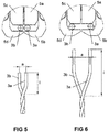
- eine Detailansicht von ersten Klemmbacken mit geklemmten Leitungen in geringem Abstand zueinander;
- Fig. 6
- eine Detailansicht von ersten Klemmbacken mit geklemmten Leitungen in grösserem Abstand zueinander;
- Fig. 7
- eine Detailansicht eines Verdrillkopfes mit geklemmten Leitungen in geringem Abstand zueinander;
- Fig. 8
- eine Detailansicht eines Verdrillkopfes mit geklemmten Leitungen in grösserem Abstand zueinander;
- Fig. 9
- die Zuführvorrichtung aus
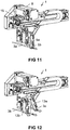
Fig. 1 in Bereitschaftsstellung; - Fig. 10
- die Zuführvorrichtung mit positioniertem ersten Lineargreifer;
- Fig. 11
- wie
Fig. 10 , nur mit erfasster erster Leitung; - Fig. 12
- die Zuführvorrichtung mit weggeschwenktem ersten Lineargreifer;
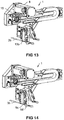
- Fig. 13
- die Zuführvorrichtung mit positioniertem zweiten Lineargreifer;
- Fig. 14
- wie
Fig. 13 , nur mit erfasster zweiter Leitung; - Fig. 15
- die Zuführvorrichtung mit einem gewählten Leitungsabstand entsprechend eingestellten Lineargreifern;
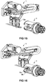
- Fig. 16
- die Zuführvorrichtung in einer Übergabeposition zum Verdrillkopf;
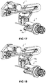
- Fig. 17
- wie
Fig. 16 , nur mit aktivierten zweiten Klemmbacken des Verdrillkopfs; - Fig. 18
- wie
Fig. 17 , nur mit gelösten ersten Klemmbacken der Zuführvorrichtung; - Fig. 19
- eine schematische Darstellung von drei Greifern mit ersten Klemmbacken in einer Bereitschaftsposition;
- Fig. 20
- die Anordnung aus
Fig. 19 mit einer ersten Leitung, die vom ersten Greifer erfasst wurde; - Fig. 21
- die Anordnung aus
Fig. 19 mit weggeschwenktem ersten Greifer und einer zweiten Leitung, die vom zweiten Greifer erfasst wurde; - Fig. 22
- die Anordnung aus
Fig. 19 mit weggeschwenktem ersten und zweiten Greifer und einer dritten Leitung, die vom dritten Greifer erfasst wurde; - Fig. 23
- die Anordnung aus
Fig. 19 mit einem gewählten Leitungsabstand entsprechend eingestellten Greifern; - Fig. 24
- wie
Fig. 23 , nur mit zweiten Klemmbacken eines Verdrillkopfs, welche die drei Leitungen erfasst haben; - Fig. 25
- wie
Fig. 24 , nur mit gelösten ersten Klemmbacken und - Fig. 26
- wie
Fig. 25 , nur mit weggeschwenkten Greifern.
- Fig. 1
- an example of a twisting device;
- Fig. 2
- a first, exemplary and schematically illustrated embodiment of flat jaws of a feeding device;
- Fig. 3
- as
Fig. 2 , only with serrated jaws; - Fig. 4
- as
Fig. 2 , only with recesses for the recording of lines; - Fig. 5
- a detailed view of first jaws with clamped lines at a small distance from each other;
- Fig. 6
- a detailed view of first jaws with clamped lines at a greater distance from each other;
- Fig. 7
- a detailed view of a twisting head with clamped lines at a small distance from each other;
- Fig. 8
- a detailed view of a twisting head with clamped lines at a greater distance from each other;
- Fig. 9
- the feeder off
Fig. 1 in ready position; - Fig. 10
- the feeder with positioned first linear gripper;
- Fig. 11
- as
Fig. 10 , only with detected first line; - Fig. 12
- the feeding device with the first linear gripper pivoted away;
- Fig. 13
- the feeding device with positioned second linear gripper;
- Fig. 14
- as
Fig. 13 , only with detected second line; - Fig. 15
- the feeder with a selected line spacing according to adjusted linear grippers;
- Fig. 16
- the feeding device in a transfer position to the twisting head;
- Fig. 17
- as
Fig. 16 , only with activated second clamping jaws of the twisting head; - Fig. 18
- as
Fig. 17 , only with dissolved first jaws of the feeder; - Fig. 19
- a schematic representation of three grippers with first jaws in a standby position;
- Fig. 20
- the arrangement
Fig. 19 with a first line detected by the first gripper; - Fig. 21
- the arrangement
Fig. 19 with pivoted first gripper and a second line, which was detected by the second gripper; - Fig. 22
- the arrangement
Fig. 19 with the first and second grippers swung away and a third line detected by the third gripper; - Fig. 23
- the arrangement
Fig. 19 with a selected line spacing according to set grippers; - Fig. 24
- as
Fig. 23 , only with second clamping jaws of a twisting head, which have detected the three lines; - Fig. 25
- as
Fig. 24 , only with loosened first jaws and - Fig. 26
- as
Fig. 25 , only with swung-away grippers.
Die ersten Klemmbacken 5a..5d sind in einer Klemmstellung derart gegeneinander bewegbar, dass ein Abstand geklemmter Leitungsenden 2a, 2b veränderbar ist. Dazu weist die Verdrilleinrichtung eine Steuerung 7 auf, welche mit einem Antrieb 8 für die ersten Klemmbacken 5a..5d verbunden und für dessen Ansteuerung eingerichtet ist, derart, dass der Abstand zwischen geklemmten Leitungsenden 2a, 2b vor der Übergabe in den Verdrillkopf 4 auf einen einstellbaren Wert gebracht wird. Wie das Einstellen des Abstands konkret funktioniert, wird später noch im Detail erläutert.The first clamping jaws 5. 5... 5 d are movable relative to one another in a clamping position such that a distance of clamped line ends 2 a, 2 b is variable. For this purpose, the twisting device on a
In einer weiteren alternativen Ausführungsform ist die Breite b zumindest doppelt so gross wie der Durchmesser d der Leitung 3a respektive des Leitungsendes 2a. Mit anderen Worten ist der zwischen den vollständig geöffneten ersten Klemmbacken 5a, 5b liegende Zwischenraum in einer Bewegungsrichtung A zum Verändern der Position des geklemmten Leitungsendes 2a zumindest zweimal so gross ist wie der Durchmesser d der Leitung 3a beziehungsweise des Leitungsendes 2a, für welche die Zuführvorrichtung 1 spezifiziert ist.In a further alternative embodiment, the width b is at least twice as large as the diameter d of the
In noch einer weiteren vorteilhaften Ausführungsform beträgt die Breite b zumindest 9 mm. Mit anderen Worten ist der zwischen den vollständig geöffneten ersten Klemmbacken 5a, 5b liegende Zwischenraum in einer Bewegungsrichtung A zum Verändern der Position des geklemmten Leitungsendes 2a zumindest 9 mm gross.In yet another advantageous embodiment, the width b is at least 9 mm. In other words, the gap between the fully opened
Eine beispielhafte, konkret ausgeführte Verdrilleinrichtung ist für das Verdrillen von Kabeln 3a, 3b mit einem Querschnitt von 0,35 mm2 bis zu 2,5 mm2 spezifiziert und kann Kabeln mit einem Durchmesser von bis zu 3 mm verarbeiten. Die Klemmbacken weisen dabei eine Breite b von 9 mm auf, wodurch der Mittenabstand der Leitungen 3a, 3b maximal 15 mm beträgt (vergleiche auch den Abstand a in den
Die
In der
Dünne Leitungen 3a, 3b, gegebenenfalls mit kleinen (Crimp)Kontakten und kleinen Dichtungen, können zueinander in einem kleineren Leitungsabstand a angeordnet werden als Leitungen 3a, 3b mit grossem Aussendurchmesser, welche insbesondere mit grossvolumigen (Crimp)Kontakten und Dichtungen bestückt sind. Auf diese Weise können die Leitungen 3a, 3b auf grösstmöglicher Länge verdrillt werden.
Die bisherigen Darstellungen zeigen Beispiele, in denen die ersten Klemmbacken 5a..5d in einer Klemmstellung derart gegeneinander bewegbar sind, dass ein Abstand zwischen zwei geklemmten Leitungsenden 3a, 3b veränderbar ist, wodurch insbesondere Twisted-Pair-Leitungen mit unterschiedlich beabstandeten Leitungsenden 2a, 2b hergestellt werden können.The previous illustrations show examples in which the
Dies ist aber nicht die einzig denkbare Ausführungsform. Möglich ist beispielsweise auch, dass die ersten Klemmbacken 5a..5d in einer Klemmstellung derart gegeneinander bewegbar sind, dass ein Abstand zwischen drei geklemmten Leitungsenden veränderbar ist (siehe
Ein Verfahren zum Verdrillen von zwei Leitungen 3a, 3b mit Hilfe der Zuführvorrichtung 1 und dem Verdrillkopf 4 wird nun anhand der
Weiterhin sind in der
Das Verfahren zum Verdrillen der beiden Leitungen 3a, 3b mit Hilfe der Zuführvorrichtung 1 mit ersten Klemmbacken 5a..5d und der Verdrilleinrichtung 1 mit dem Verdrillkopf 4 mit zweiten Klemmbacken 6a, 6b, umfasst somit folgende Schritte:
Klemmen der Leitungsenden Klemmbacken 5a..5d der Zuführvorrichtung 1,Bewegen der Zuführeinrichtung 1 in eine Übergabestellungmit dem Verdrillkopf 4, in der die ersten Klemmbacken 5a..5d der Zuführvorrichtung 1 und die zweiten Klemmbacken 6a, 6b des Verdrillkopfs 4 einander gegenüber stehen,- Klemmen der der Leitungsenden 2a, 2b zwischen den zweiten
Klemmbacken Verdrillkopfs 4, - Lösen der ersten Klemmbacken 5a..
5d der Zuführvorrichtung 1 und - Verdrillen der besagten Leitungen 3a, 3d durch Drehen des
Verdrillkopfs 4.
- Clamping the line ends 2a, 2b of said leads 3a, 3b between the
first jaws 5a..5d of thefeeder device 1, - Moving the
feeder 1 in a transfer position with the twistinghead 4, in which thefirst jaws 5a..5d of thefeeder 1 and thesecond jaws head 4 face each other, - Clamping the line ends 2a, 2b between the
second jaws head 4, - Loosening the
first jaws 5a..5d of thefeeder 1 and - Twisting said
lines 3a, 3d by turning the twisting head 4th
Der Abstand zwischen geklemmten Leitungsenden 2a, 2b wird dabei durch Bewegen der ersten Klemmbacken 5a..5d in einer Klemmstellung vor dem Klemmen der Leitungsenden 2a, 2b in den zweiten Klemmbacken 6a, 6b des Verdrillkopfs 4 auf einen einstellbaren Wert gebracht. Insbesondere sind für den Abstand zwischen den geklemmten Leitungsenden 2a, 2b wenigstens zwei unterschiedliche Werte auswählbar.The distance between clamped line ends 2a, 2b is brought by moving the
In dem gezeigten Beispiel werden die Leitungsenden 2a, 2b von der Zuführeinrichtung 1 nacheinander einzeln und vom Verdrillkopf 4 gleichzeitig gemeinsam erfasst und geklemmt. Denkbar ist natürlich aber auch, dass die Leitungsenden 2a, 2b von der Zuführeinrichtung 1 ebenfalls gleichzeitig gemeinsam erfasst und geklemmt werden.In the example shown, the line ends 2a, 2b are detected by the
Weiterhin wird eine variierbare Stellung der ersten Klemmbacken 5a..5d vor dem Klemmen der Leitungsenden 2a, 2b einem gewählten Abstand a entsprechend zwischen den Leitungsenden 2a, 2b eingestellt, und die ersten Klemmbacken 5a..5d werden vor dem Klemmen der Leitungsenden 2a, 2b in den zweiten Klemmbacken 6a, 6b des Verdrillkopfs 4 in eine fix vorgegebene Stellung bewegt (siehe dazu insbesondere die
Selbstverständlich ist dies nicht die einzig denkbare Möglichkeit. Vorstellbar ist beispielsweise auch, dass die ersten Klemmbacken 5a..5d vor dem Klemmen der Leitungsenden 2a, 2b in eine fix vorgegebene Stellung bewegt werden und eine variierbare Stellung der ersten Klemmbacken 5a..5d vor dem Klemmen der Leitungsenden 2a, 2b in den zweiten Klemmbacken 6a, 6b des Verdrillkopfs 4 entsprechend eines gewählten Abstands a zwischen den Leitungsenden 2a, 3b eingestellt wird. Konkret bedeutet dies, dass die Lineargreifer 13a, 13b in den
Generell können die ersten Klemmbacken 5a..5d zum Klemmen eines Leitungsendes 2a, 2b zueinander verschiebbar und zum Verändern des Abstands geklemmter Leitungsenden 2a, 2b ohne Beeinflussung einer Klemmstellung zueinander verdrehbar gelagert sein, so wie dies in den
Weiterhin können auch die zweiten Klemmbacken 6a, 6b zum Klemmen eines Leitungsendes 2a, 2b zueinander wie in den
- c) im Wesentlichen flach sind oder
- d) mehr als zwei, insbesondere mehr als drei, halbschalenförmigen Einkerbungen zur Aufnahme je eines Leitungsendes 2a, 2b umfassen.
- c) are essentially flat or
- d) comprise more than two, in particular more than three, half-shell-shaped indentations for receiving a
respective line end
Die
In der
Anschliessend werden die Klemmbacken 5a..5f in jene Stellung zueinander gefahren, in der sie die Leitungen 3a..3c an den Verdrillkopf 4 übergeben. Dieser Zustand ist in
In der
An dieser Stelle wird angemerkt, dass die zu der in den
Abschliessend wird auch angemerkt, dass die dargestellten Anordnungen in der Realität auch mehr Bauteile als dargestellt umfassen können.Finally, it is also noted that the illustrated arrangements can in reality also comprise more components than illustrated.
- 11
- Zuführvorrichtungfeeder
- 2a, 2b2a, 2b
- Leitungsendecable end
- 3a..3c3a..3c
- Leitungmanagement
- 44
- Verdrillkopftwisting
- 5a..5f5a..5f
-
erste Klemmbacken der Zuführvorrichtung 1first jaws of the
feeding device 1 - 6a, 6b6a, 6b
-
zweite Klemmbacken des Verdrillkopfes 4second jaws of the
twisting 4 - 77
- Steuerungcontrol
- 88th
- Antriebdrive
- 9a, 9b9a, 9b
- Klemmflächenclamping surfaces
- 1010
- Zahnradgear
- 11a11a
- (Crimp)kontakt(Crimp) contact
- 12a12a
- Dichtungpoetry
- 13a, 13b13a, 13b
- Lineargreiferlinear gripper
- 1414
- Pneumatikzylinderpneumatic cylinder
- 1515
- Horizontalführunghorizontal guide
- 1616
- Schlittencarriage
- 1717
-
Drehlager des ersten Lineargreifers 13aRotary bearing of the first
linear gripper 13a - 1818
-
Vertikalführung des zweiten Lineargreifers 13bVertical guide of the second
linear gripper 13b - AA
- Bewegungsrichtungmovement direction
- BB
- Klemmrichtungclamping direction
- aa
- Leitungsabstandline spacing
- bb
- ZwischenraumbreiteGap width
- dd
- Durchmesser LeitungDiameter line
- hH
- ZwischenraumhöheGap height
- II
- unverdrillte Leitungslängeuntwisted cable length
- tt
- Tiefe der EinkerbungDepth of notch
- zz
- Zahnhöhetooth height
Claims (16)
- Twisting apparatus for twisting at least two conductors (3a..3c),
comprising a feed device (1) for feeding conductor ends (2a...2c) of at least two conductors (3a...3c) and a rotatably mounted twisting head (4) for twisting said conductors (3a...3c), wherein- the feed device (1) has first clamping jaws (5a...5f) which are movable by a drive unit (8) for clamping the conductor ends (2a...2c),- the twisting head (4) has second clamping jaws (6a, 6b) for clamping the conductor ends (2a...2c),- the feed device (1) and the twisting head (4) are movable relative to one another into a transfer position, in which the first clamping jaws (5a...5f) and the second clamping jaws (6a, 6b) are positioned opposite each other, and- the first clamping jaws (5a...5f) in a clamping position can be moved relative to each other in such manner that a distance (a) between clamped conductor ends (2a...2c) can be changed,characterized in that a controller (7) is connected to the drive unit (8) for the first clamping jaws (5a...5f) and is configured for activation thereof in such manner that the distance (a) between clamped conductor ends (2a...2c) is brought to a predefinable value before the transfer into the twisting head (4), wherein said distance (a) is selectable from at least two different values. - Twisting apparatus according to Claim 1, characterized in that when first clamping jaws (5a...5f) are fully opened an intermediate space between said jaws expands at least twice as far in a direction of movement (A) for changing the distance between clamped conductor ends (2a..2c) as in a clamping direction (B) of the first clamping jaws (5a...5f) for clamping the conductor ends (2a...2c).
- Twisting apparatus according to Claim 1 or 2, characterized in that when first clamping jaws (5a...5f) are fully opened an intermediate space between said jaws is at least twice as great in a direction of movement for changing the distance (A) between clamped conductor ends (2a..2c) as a diameter (d) of the conductor ends (2a...2c) for which the feed device (1) is specified.
- Twisting apparatus according to any one of Claims 1 to 3, characterized in that when first clamping jaws (5a...5f) are fully opened an intermediate space between said jaws has a dimension of at least 9 mm in a direction of movement for changing the distance between clamped conductor ends (2a..2c).
- Twisting apparatus according to any one of Claims 1 to 4, characterized in that the first clamping jaws (5a...5f) have clamping surfaces (9a, 9b) facing each other, whicha) are substantially planar, orb) comprise more than one half-shell shaped groove for receiving one conductor end (2a...2c) each.
- Twisting apparatus according to any one of Claims 1 to 5, characterized in that the first clamping jaws (5a...5d) in a clamped position are movable relative to each other in such manner that a distance (a) between two clamped conductor ends (2a, 2b) can be changed.
- Twisting apparatus according to any one of Claims 1 to 5, characterized in that the first clamping jaws (5a...5f) in a clamped position are movable relative to each other in such manner that a distance (a) between three clamped conductor ends (2a...2c) can be changed.
- Twisting apparatus according to any one of Claims 1 to 7, characterized in that the first clamping jaws (5a...5f) are mounted so as to be movable relative to each other for clamping a conductor end (2a...2c).
- Twisting apparatus according to any one of Claims 1 to 8, characterized in that the first clamping jaws (5a...5f) are mounted so as to be rotatable relative to each other changing the distance (a) between clamped conductor ends (2a...2c) without affecting a clamping position.
- Twisting apparatus (1) according to any one of Claims 1 to 9,
characterized in that
the second clamping jaws (6a, 6b) have clamping surfaces facing each other, whichc) are substantially planar, ord) comprise more than two half-shell shaped grooves for receiving one conductor end (2a...2c) each. - Twisting apparatus (1) according to Claim 10, characterized in that the second clamping jaws (6a, 6b) are mounted so as to be movable relative to each other for clamping a conductor end (2a...2c).
- Method for twisting at least two conductors (3a, 3c) using a twisting apparatus according to any one of Claims 1-11, comprising a feed device (1) with first clamping jaws (5a...5f) and a rotatably mounted (4) with second clamping jaws (6a, 6b) comprising the steps- clamping conductor ends (2a...2c) of said conductors (3a...3c) between the first clamping jaws (5a...5f) of the feed device (1),- moving the feed device (1) into a transfer position with the twisting head (4), in which the first clamping jaws (5a...5f) of the feed device (1) and the second clamping jaws (6a, 6b) of the twisting head (4) are positioned opposite each other,- clamping the conductor ends (2a...2c) between the second clamping jaws (6a, 6b) of the twisting head (4),- releasing the first clamping jaws (5a...5f) of the feed device (1) and- twisting said conductors (3a...3c) by turning the twisting head (4),characterized in that
the distance (a) between clamped conductor ends (2a...2c) is brought to a predefinable value by moving the first clamping jaws (5a...5f) in a clamping position before clamping of the conductor ends (2a...2c) in the second clamping jaws (6a, 6b), wherein said distance (a) is selected from at least two different values. - Method according to Claim 12, characterized in that the conductor ends (2a...2c) are gripped and clamped individually one after the other by the feed device (1) and simultaneously all together by the twisting head (4).
- Method according to Claim 12 or 13, characterized in that the conductor ends (2a...2c) are gripped and clamped simultaneously all together by the feed device (1) and simultaneously all together by the twisting head (4).
- Method according to any one of Claims 12 to 14, characterized in that a variable position of the first clamping jaws (5a...5f) corresponding to a selected distance (a) between the conductor ends (2a...2c) is set before the clamping of the conductor ends (2a...2c), and the first clamping jaws (5a...5f) moved to a fixed, predetermined position before the clamping of the conductor ends (2a...2c) in the second clamping jaws (6a, 6b) of the twisting head (4).
- Method according to any one of Claims 12 to 15, characterized in that the first clamping jaws (5a...5f) moved to a fixed, predetermined position before the clamping of the conductor ends (2a...2c) and a variable position of the first clamping jaws (5a...5f) corresponding to a selected distance (a) between the conductor ends (2a...2c) is set before the clamping of the conductor ends (2a...2c) in the second clamping jaws (6a, 6b) of the twisting head (4).
Priority Applications (8)
| Application Number | Priority Date | Filing Date | Title |
|---|---|---|---|
| EP14190317.9A EP3012842B1 (en) | 2014-10-24 | 2014-10-24 | Twisting device with an adjustable distance between the cable ends |
| PT14190317T PT3012842T (en) | 2014-10-24 | 2014-10-24 | Twisting device with an adjustable distance between the cable ends |
| SG10201508421QA SG10201508421QA (en) | 2014-10-24 | 2015-10-10 | A twist application device with an adjustable distance between the conductor ends |
| KR1020150145890A KR20160048662A (en) | 2014-10-24 | 2015-10-20 | A twist application device with an adjustable distance between the conductor ends |
| JP2015209023A JP2016085974A (en) | 2014-10-24 | 2015-10-23 | Twist application device with adjustable distance between conductor ends |
| CN201510696158.1A CN105552680B (en) | 2014-10-24 | 2015-10-23 | Twisting device with adjustable spacing of conductor ends |
| US14/922,453 US10046380B2 (en) | 2014-10-24 | 2015-10-26 | Twist application device with an adjustable distance between the conductor ends |
| US15/405,378 US10052676B2 (en) | 2014-10-24 | 2017-01-13 | Twist application device with an adjustable distance between the conductor ends |
Applications Claiming Priority (1)
| Application Number | Priority Date | Filing Date | Title |
|---|---|---|---|
| EP14190317.9A EP3012842B1 (en) | 2014-10-24 | 2014-10-24 | Twisting device with an adjustable distance between the cable ends |
Publications (2)
| Publication Number | Publication Date |
|---|---|
| EP3012842A1 EP3012842A1 (en) | 2016-04-27 |
| EP3012842B1 true EP3012842B1 (en) | 2019-06-12 |
Family
ID=51865986
Family Applications (1)
| Application Number | Title | Priority Date | Filing Date |
|---|---|---|---|
| EP14190317.9A Not-in-force EP3012842B1 (en) | 2014-10-24 | 2014-10-24 | Twisting device with an adjustable distance between the cable ends |
Country Status (6)
| Country | Link |
|---|---|
| EP (1) | EP3012842B1 (en) |
| JP (1) | JP2016085974A (en) |
| KR (1) | KR20160048662A (en) |
| CN (1) | CN105552680B (en) |
| PT (1) | PT3012842T (en) |
| SG (1) | SG10201508421QA (en) |
Families Citing this family (4)
| Publication number | Priority date | Publication date | Assignee | Title |
|---|---|---|---|---|
| DE102016109155B3 (en) | 2016-05-18 | 2017-08-03 | Lisa Dräxlmaier GmbH | Twisting machine, tandem twisting machine and method for loading a twisting head |
| SG11202002673PA (en) * | 2017-11-10 | 2020-04-29 | Schleuniger Holding Ag | Twisting appliance and twisting head device and method for twisting or stranding cables |
| CN108657872B (en) * | 2018-04-02 | 2023-06-20 | 浙江一丁点工艺品有限公司 | Velvet strip circulation feeding device |
| CN108975053B (en) * | 2018-06-21 | 2020-11-10 | 芜湖文青机械设备设计有限公司 | Wire harness winding device |
Family Cites Families (10)
| Publication number | Priority date | Publication date | Assignee | Title |
|---|---|---|---|---|
| US3827465A (en) * | 1972-03-20 | 1974-08-06 | Gardner Denver Co | Apparatus for forming twisted pairs of conductor wire |
| US4341014A (en) * | 1980-05-07 | 1982-07-27 | Cooper Industries, Inc. | Method and apparatus for interconnecting pairs of terminals with a pretwisted pair of insulated wires |
| US5238177A (en) * | 1992-08-10 | 1993-08-24 | Flexible Steel Lacing Company | Method and apparatus for forming conveyor belt hinge pins |
| DE59914354D1 (en) * | 1998-08-31 | 2007-07-12 | Komax Holding Ag | Device for merging ladders |
| EP0984530B1 (en) * | 1998-08-31 | 2007-05-30 | komax Holding AG | Device for bringing conductors together |
| EP1032095B1 (en) | 1999-02-23 | 2013-05-22 | Komax Holding AG | Method and device for processing and twisting a conductor pair |
| US6289944B1 (en) * | 1999-02-23 | 2001-09-18 | Komax Holding Ag | Method and equipment for the treatment and twisting together of a conductor pair |
| JP2003217371A (en) * | 2002-01-23 | 2003-07-31 | Auto Network Gijutsu Kenkyusho:Kk | Method and device for manufacturing twisted pair wire |
| WO2013068990A1 (en) * | 2011-11-11 | 2013-05-16 | Schleuniger Holding Ag | Twisting device |
| JP6282929B2 (en) * | 2014-05-16 | 2018-02-21 | 日本オートマチックマシン株式会社 | Electric wire twisting device, twisted cable manufacturing device, electric wire twisting method, and twisted cable manufacturing method |
-
2014
- 2014-10-24 PT PT14190317T patent/PT3012842T/en unknown
- 2014-10-24 EP EP14190317.9A patent/EP3012842B1/en not_active Not-in-force
-
2015
- 2015-10-10 SG SG10201508421QA patent/SG10201508421QA/en unknown
- 2015-10-20 KR KR1020150145890A patent/KR20160048662A/en unknown
- 2015-10-23 CN CN201510696158.1A patent/CN105552680B/en not_active Expired - Fee Related
- 2015-10-23 JP JP2015209023A patent/JP2016085974A/en not_active Ceased
Non-Patent Citations (1)
| Title |
|---|
| None * |
Also Published As
| Publication number | Publication date |
|---|---|
| CN105552680A (en) | 2016-05-04 |
| EP3012842A1 (en) | 2016-04-27 |
| KR20160048662A (en) | 2016-05-04 |
| SG10201508421QA (en) | 2016-05-30 |
| JP2016085974A (en) | 2016-05-19 |
| CN105552680B (en) | 2020-04-24 |
| PT3012842T (en) | 2019-09-10 |
Similar Documents
| Publication | Publication Date | Title |
|---|---|---|
| EP3012841A1 (en) | Device for feeding pipe ends to a processing device | |
| EP3301768B1 (en) | Method and device for rotational alignment of preconfigured cable ends of a wire harness | |
| EP3104471B1 (en) | Cable processing device for processing cable cores of a multi-core cable | |
| EP3301769B1 (en) | Vorrichtung und verfahren zum bestücken eines steckergehäuses mit konfektionierten kabelenden eines kabelstrangs | |
| EP3012842B1 (en) | Twisting device with an adjustable distance between the cable ends | |
| EP0161400A1 (en) | Method of dentistry and device for bending a piece of wire and subjecting it to a torsional stress | |
| EP3052256B1 (en) | Bending press and bending method | |
| EP2289643B1 (en) | Device for bending elongated workpieces | |
| EP2897770B1 (en) | Twin gripper | |
| EP3557592B1 (en) | Device and method for twisting a first and second electrical single wire line to form a cable pair | |
| CH684374A5 (en) | Kabelzuführungs- and -wechseleinrichtung for a wire processing machine. | |
| DE202009004913U1 (en) | Device for twisting lines | |
| CH712087B1 (en) | Centering unit, crimping device and cable processing system. | |
| DE102010017981B4 (en) | Setup and procedure for merging ladders | |
| EP3614821A1 (en) | Wiring robot and method of wiring, system and method for scheduling wiring, system and method for capturing of components | |
| DE202010001324U1 (en) | Device for twisting lines | |
| EP3804048B1 (en) | Device and method for processing an end of an electrical cable | |
| EP3652817B1 (en) | Wire handling device | |
| DE202016009044U1 (en) | Production plant for the production of workpieces from sheet metal | |
| EP2779327B1 (en) | Cable rotating pincer and method of guiding an electrical conductor | |
| DE102016109155B3 (en) | Twisting machine, tandem twisting machine and method for loading a twisting head | |
| DE102012213391A1 (en) | Device for twisting and aligning non-twisted end of cable for transmission system, has gripping element gripping ends of wires of cable and/or plug contacts such that plug contacts remain unchanged to each other after removal of contacts | |
| EP0844704A2 (en) | Manufacturing method of twisted ready-made lines and device for carrying out the method | |
| DE3315336A1 (en) | COMBINED PROGRAMMED CUTTING DEVICE | |
| DE19735655C2 (en) | Method for producing twisted, assembled cables and device for carrying out the method |
Legal Events
| Date | Code | Title | Description |
|---|---|---|---|
| PUAI | Public reference made under article 153(3) epc to a published international application that has entered the european phase |
Free format text: ORIGINAL CODE: 0009012 |
|
| AK | Designated contracting states |
Kind code of ref document: A1 Designated state(s): AL AT BE BG CH CY CZ DE DK EE ES FI FR GB GR HR HU IE IS IT LI LT LU LV MC MK MT NL NO PL PT RO RS SE SI SK SM TR |
|
| AX | Request for extension of the european patent |
Extension state: BA ME |
|
| STAA | Information on the status of an ep patent application or granted ep patent |
Free format text: STATUS: REQUEST FOR EXAMINATION WAS MADE |
|
| 17P | Request for examination filed |
Effective date: 20161027 |
|
| RBV | Designated contracting states (corrected) |
Designated state(s): AL AT BE BG CH CY CZ DE DK EE ES FI FR GB GR HR HU IE IS IT LI LT LU LV MC MK MT NL NO PL PT RO RS SE SI SK SM TR |
|
| GRAP | Despatch of communication of intention to grant a patent |
Free format text: ORIGINAL CODE: EPIDOSNIGR1 |
|
| STAA | Information on the status of an ep patent application or granted ep patent |
Free format text: STATUS: GRANT OF PATENT IS INTENDED |
|
| RIC1 | Information provided on ipc code assigned before grant |
Ipc: H01B 13/00 20060101ALN20190215BHEP Ipc: H01B 13/02 20060101AFI20190215BHEP Ipc: B65H 51/18 20060101ALI20190215BHEP |
|
| INTG | Intention to grant announced |
Effective date: 20190307 |
|
| GRAS | Grant fee paid |
Free format text: ORIGINAL CODE: EPIDOSNIGR3 |
|
| GRAA | (expected) grant |
Free format text: ORIGINAL CODE: 0009210 |
|
| STAA | Information on the status of an ep patent application or granted ep patent |
Free format text: STATUS: THE PATENT HAS BEEN GRANTED |
|
| AK | Designated contracting states |
Kind code of ref document: B1 Designated state(s): AL AT BE BG CH CY CZ DE DK EE ES FI FR GB GR HR HU IE IS IT LI LT LU LV MC MK MT NL NO PL PT RO RS SE SI SK SM TR |
|
| REG | Reference to a national code |
Ref country code: GB Ref legal event code: FG4D Free format text: NOT ENGLISH |
|
| REG | Reference to a national code |
Ref country code: CH Ref legal event code: EP |
|
| REG | Reference to a national code |
Ref country code: AT Ref legal event code: REF Ref document number: 1143639 Country of ref document: AT Kind code of ref document: T Effective date: 20190615 |
|
| REG | Reference to a national code |
Ref country code: DE Ref legal event code: R096 Ref document number: 502014011907 Country of ref document: DE |
|
| REG | Reference to a national code |
Ref country code: IE Ref legal event code: FG4D Free format text: LANGUAGE OF EP DOCUMENT: GERMAN |
|
| REG | Reference to a national code |
Ref country code: CH Ref legal event code: NV Representative=s name: ROSENICH PAUL; KUENSCH JOACHIM PATENTBUERO PAU, LI |
|
| REG | Reference to a national code |
Ref country code: PT Ref legal event code: SC4A Ref document number: 3012842 Country of ref document: PT Date of ref document: 20190910 Kind code of ref document: T Free format text: AVAILABILITY OF NATIONAL TRANSLATION Effective date: 20190820 |
|
| REG | Reference to a national code |
Ref country code: NL Ref legal event code: MP Effective date: 20190612 |
|
| REG | Reference to a national code |
Ref country code: LT Ref legal event code: MG4D |
|
| PG25 | Lapsed in a contracting state [announced via postgrant information from national office to epo] |
Ref country code: FI Free format text: LAPSE BECAUSE OF FAILURE TO SUBMIT A TRANSLATION OF THE DESCRIPTION OR TO PAY THE FEE WITHIN THE PRESCRIBED TIME-LIMIT Effective date: 20190612 Ref country code: NO Free format text: LAPSE BECAUSE OF FAILURE TO SUBMIT A TRANSLATION OF THE DESCRIPTION OR TO PAY THE FEE WITHIN THE PRESCRIBED TIME-LIMIT Effective date: 20190912 Ref country code: HR Free format text: LAPSE BECAUSE OF FAILURE TO SUBMIT A TRANSLATION OF THE DESCRIPTION OR TO PAY THE FEE WITHIN THE PRESCRIBED TIME-LIMIT Effective date: 20190612 Ref country code: SE Free format text: LAPSE BECAUSE OF FAILURE TO SUBMIT A TRANSLATION OF THE DESCRIPTION OR TO PAY THE FEE WITHIN THE PRESCRIBED TIME-LIMIT Effective date: 20190612 Ref country code: AL Free format text: LAPSE BECAUSE OF FAILURE TO SUBMIT A TRANSLATION OF THE DESCRIPTION OR TO PAY THE FEE WITHIN THE PRESCRIBED TIME-LIMIT Effective date: 20190612 Ref country code: LT Free format text: LAPSE BECAUSE OF FAILURE TO SUBMIT A TRANSLATION OF THE DESCRIPTION OR TO PAY THE FEE WITHIN THE PRESCRIBED TIME-LIMIT Effective date: 20190612 |
|
| PGFP | Annual fee paid to national office [announced via postgrant information from national office to epo] |
Ref country code: PT Payment date: 20190925 Year of fee payment: 6 |
|
| PG25 | Lapsed in a contracting state [announced via postgrant information from national office to epo] |
Ref country code: BG Free format text: LAPSE BECAUSE OF FAILURE TO SUBMIT A TRANSLATION OF THE DESCRIPTION OR TO PAY THE FEE WITHIN THE PRESCRIBED TIME-LIMIT Effective date: 20190912 Ref country code: RS Free format text: LAPSE BECAUSE OF FAILURE TO SUBMIT A TRANSLATION OF THE DESCRIPTION OR TO PAY THE FEE WITHIN THE PRESCRIBED TIME-LIMIT Effective date: 20190612 Ref country code: LV Free format text: LAPSE BECAUSE OF FAILURE TO SUBMIT A TRANSLATION OF THE DESCRIPTION OR TO PAY THE FEE WITHIN THE PRESCRIBED TIME-LIMIT Effective date: 20190612 Ref country code: GR Free format text: LAPSE BECAUSE OF FAILURE TO SUBMIT A TRANSLATION OF THE DESCRIPTION OR TO PAY THE FEE WITHIN THE PRESCRIBED TIME-LIMIT Effective date: 20190913 |
|
| PG25 | Lapsed in a contracting state [announced via postgrant information from national office to epo] |
Ref country code: RO Free format text: LAPSE BECAUSE OF FAILURE TO SUBMIT A TRANSLATION OF THE DESCRIPTION OR TO PAY THE FEE WITHIN THE PRESCRIBED TIME-LIMIT Effective date: 20190612 Ref country code: CZ Free format text: LAPSE BECAUSE OF FAILURE TO SUBMIT A TRANSLATION OF THE DESCRIPTION OR TO PAY THE FEE WITHIN THE PRESCRIBED TIME-LIMIT Effective date: 20190612 Ref country code: SK Free format text: LAPSE BECAUSE OF FAILURE TO SUBMIT A TRANSLATION OF THE DESCRIPTION OR TO PAY THE FEE WITHIN THE PRESCRIBED TIME-LIMIT Effective date: 20190612 Ref country code: EE Free format text: LAPSE BECAUSE OF FAILURE TO SUBMIT A TRANSLATION OF THE DESCRIPTION OR TO PAY THE FEE WITHIN THE PRESCRIBED TIME-LIMIT Effective date: 20190612 Ref country code: NL Free format text: LAPSE BECAUSE OF FAILURE TO SUBMIT A TRANSLATION OF THE DESCRIPTION OR TO PAY THE FEE WITHIN THE PRESCRIBED TIME-LIMIT Effective date: 20190612 |
|
| PGFP | Annual fee paid to national office [announced via postgrant information from national office to epo] |
Ref country code: DE Payment date: 20191031 Year of fee payment: 6 Ref country code: CH Payment date: 20190911 Year of fee payment: 6 |
|
| PG25 | Lapsed in a contracting state [announced via postgrant information from national office to epo] |
Ref country code: SM Free format text: LAPSE BECAUSE OF FAILURE TO SUBMIT A TRANSLATION OF THE DESCRIPTION OR TO PAY THE FEE WITHIN THE PRESCRIBED TIME-LIMIT Effective date: 20190612 Ref country code: ES Free format text: LAPSE BECAUSE OF FAILURE TO SUBMIT A TRANSLATION OF THE DESCRIPTION OR TO PAY THE FEE WITHIN THE PRESCRIBED TIME-LIMIT Effective date: 20190612 Ref country code: IS Free format text: LAPSE BECAUSE OF FAILURE TO SUBMIT A TRANSLATION OF THE DESCRIPTION OR TO PAY THE FEE WITHIN THE PRESCRIBED TIME-LIMIT Effective date: 20191012 |
|
| PGFP | Annual fee paid to national office [announced via postgrant information from national office to epo] |
Ref country code: IT Payment date: 20191031 Year of fee payment: 6 |
|
| REG | Reference to a national code |
Ref country code: DE Ref legal event code: R097 Ref document number: 502014011907 Country of ref document: DE |
|
| PG25 | Lapsed in a contracting state [announced via postgrant information from national office to epo] |
Ref country code: TR Free format text: LAPSE BECAUSE OF FAILURE TO SUBMIT A TRANSLATION OF THE DESCRIPTION OR TO PAY THE FEE WITHIN THE PRESCRIBED TIME-LIMIT Effective date: 20190612 |
|
| PLBE | No opposition filed within time limit |
Free format text: ORIGINAL CODE: 0009261 |
|
| STAA | Information on the status of an ep patent application or granted ep patent |
Free format text: STATUS: NO OPPOSITION FILED WITHIN TIME LIMIT |
|
| PG25 | Lapsed in a contracting state [announced via postgrant information from national office to epo] |
Ref country code: PL Free format text: LAPSE BECAUSE OF FAILURE TO SUBMIT A TRANSLATION OF THE DESCRIPTION OR TO PAY THE FEE WITHIN THE PRESCRIBED TIME-LIMIT Effective date: 20190612 Ref country code: DK Free format text: LAPSE BECAUSE OF FAILURE TO SUBMIT A TRANSLATION OF THE DESCRIPTION OR TO PAY THE FEE WITHIN THE PRESCRIBED TIME-LIMIT Effective date: 20190612 |
|
| 26N | No opposition filed |
Effective date: 20200313 |
|
| PG25 | Lapsed in a contracting state [announced via postgrant information from national office to epo] |
Ref country code: IS Free format text: LAPSE BECAUSE OF FAILURE TO SUBMIT A TRANSLATION OF THE DESCRIPTION OR TO PAY THE FEE WITHIN THE PRESCRIBED TIME-LIMIT Effective date: 20200224 Ref country code: SI Free format text: LAPSE BECAUSE OF FAILURE TO SUBMIT A TRANSLATION OF THE DESCRIPTION OR TO PAY THE FEE WITHIN THE PRESCRIBED TIME-LIMIT Effective date: 20190612 Ref country code: MC Free format text: LAPSE BECAUSE OF FAILURE TO SUBMIT A TRANSLATION OF THE DESCRIPTION OR TO PAY THE FEE WITHIN THE PRESCRIBED TIME-LIMIT Effective date: 20190612 |
|
| PG2D | Information on lapse in contracting state deleted |
Ref country code: IS |
|
| PG25 | Lapsed in a contracting state [announced via postgrant information from national office to epo] |
Ref country code: LU Free format text: LAPSE BECAUSE OF NON-PAYMENT OF DUE FEES Effective date: 20191024 |
|
| REG | Reference to a national code |
Ref country code: BE Ref legal event code: MM Effective date: 20191031 |
|
| PG25 | Lapsed in a contracting state [announced via postgrant information from national office to epo] |
Ref country code: BE Free format text: LAPSE BECAUSE OF NON-PAYMENT OF DUE FEES Effective date: 20191031 |
|
| GBPC | Gb: european patent ceased through non-payment of renewal fee |
Effective date: 20191024 |
|
| REG | Reference to a national code |
Ref country code: CH Ref legal event code: PCAR Free format text: NEW ADDRESS: ROTENBODENSTRASSE 12, 9497 TRIESENBERG (LI) |
|
| PG25 | Lapsed in a contracting state [announced via postgrant information from national office to epo] |
Ref country code: FR Free format text: LAPSE BECAUSE OF NON-PAYMENT OF DUE FEES Effective date: 20191031 Ref country code: GB Free format text: LAPSE BECAUSE OF NON-PAYMENT OF DUE FEES Effective date: 20191024 Ref country code: IE Free format text: LAPSE BECAUSE OF NON-PAYMENT OF DUE FEES Effective date: 20191024 |
|
| REG | Reference to a national code |
Ref country code: AT Ref legal event code: MM01 Ref document number: 1143639 Country of ref document: AT Kind code of ref document: T Effective date: 20191024 |
|
| PG25 | Lapsed in a contracting state [announced via postgrant information from national office to epo] |
Ref country code: AT Free format text: LAPSE BECAUSE OF NON-PAYMENT OF DUE FEES Effective date: 20191024 |
|
| REG | Reference to a national code |
Ref country code: DE Ref legal event code: R119 Ref document number: 502014011907 Country of ref document: DE |
|
| PG25 | Lapsed in a contracting state [announced via postgrant information from national office to epo] |
Ref country code: CY Free format text: LAPSE BECAUSE OF FAILURE TO SUBMIT A TRANSLATION OF THE DESCRIPTION OR TO PAY THE FEE WITHIN THE PRESCRIBED TIME-LIMIT Effective date: 20190612 |
|
| REG | Reference to a national code |
Ref country code: CH Ref legal event code: PL |
|
| PG25 | Lapsed in a contracting state [announced via postgrant information from national office to epo] |
Ref country code: PT Free format text: LAPSE BECAUSE OF NON-PAYMENT OF DUE FEES Effective date: 20210426 Ref country code: MT Free format text: LAPSE BECAUSE OF FAILURE TO SUBMIT A TRANSLATION OF THE DESCRIPTION OR TO PAY THE FEE WITHIN THE PRESCRIBED TIME-LIMIT Effective date: 20190612 Ref country code: HU Free format text: LAPSE BECAUSE OF FAILURE TO SUBMIT A TRANSLATION OF THE DESCRIPTION OR TO PAY THE FEE WITHIN THE PRESCRIBED TIME-LIMIT; INVALID AB INITIO Effective date: 20141024 Ref country code: DE Free format text: LAPSE BECAUSE OF NON-PAYMENT OF DUE FEES Effective date: 20210501 |
|
| PG25 | Lapsed in a contracting state [announced via postgrant information from national office to epo] |
Ref country code: LI Free format text: LAPSE BECAUSE OF NON-PAYMENT OF DUE FEES Effective date: 20201031 Ref country code: CH Free format text: LAPSE BECAUSE OF NON-PAYMENT OF DUE FEES Effective date: 20201031 |
|
| PG25 | Lapsed in a contracting state [announced via postgrant information from national office to epo] |
Ref country code: IT Free format text: LAPSE BECAUSE OF NON-PAYMENT OF DUE FEES Effective date: 20201024 |
|
| PG25 | Lapsed in a contracting state [announced via postgrant information from national office to epo] |
Ref country code: MK Free format text: LAPSE BECAUSE OF FAILURE TO SUBMIT A TRANSLATION OF THE DESCRIPTION OR TO PAY THE FEE WITHIN THE PRESCRIBED TIME-LIMIT Effective date: 20190612 |