EP3012029B1 - Vorrichtung zur aufnahme einer flüssigen substanz - Google Patents
Vorrichtung zur aufnahme einer flüssigen substanz Download PDFInfo
- Publication number
- EP3012029B1 EP3012029B1 EP15190583.3A EP15190583A EP3012029B1 EP 3012029 B1 EP3012029 B1 EP 3012029B1 EP 15190583 A EP15190583 A EP 15190583A EP 3012029 B1 EP3012029 B1 EP 3012029B1
- Authority
- EP
- European Patent Office
- Prior art keywords
- bag
- flange
- ring cap
- neck
- respect
- Prior art date
- Legal status (The legal status is an assumption and is not a legal conclusion. Google has not performed a legal analysis and makes no representation as to the accuracy of the status listed.)
- Active
Links
- 239000012530 fluid Substances 0.000 title claims description 20
- 239000000126 substance Substances 0.000 title claims description 20
- 238000003780 insertion Methods 0.000 claims description 10
- 230000037431 insertion Effects 0.000 claims description 10
- 238000000034 method Methods 0.000 claims description 4
- 230000006835 compression Effects 0.000 claims description 2
- 238000007906 compression Methods 0.000 claims description 2
- 230000006837 decompression Effects 0.000 description 4
- 230000008878 coupling Effects 0.000 description 2
- 238000010168 coupling process Methods 0.000 description 2
- 238000005859 coupling reaction Methods 0.000 description 2
- 239000000463 material Substances 0.000 description 2
- 239000004033 plastic Substances 0.000 description 2
- 229920003023 plastic Polymers 0.000 description 2
- XAGFODPZIPBFFR-UHFFFAOYSA-N aluminium Chemical compound [Al] XAGFODPZIPBFFR-UHFFFAOYSA-N 0.000 description 1
- 229910052782 aluminium Inorganic materials 0.000 description 1
- 239000011521 glass Substances 0.000 description 1
- 238000007493 shaping process Methods 0.000 description 1
- 239000012815 thermoplastic material Substances 0.000 description 1
Images


Classifications
-
- B—PERFORMING OPERATIONS; TRANSPORTING
- B05—SPRAYING OR ATOMISING IN GENERAL; APPLYING FLUENT MATERIALS TO SURFACES, IN GENERAL
- B05B—SPRAYING APPARATUS; ATOMISING APPARATUS; NOZZLES
- B05B11/00—Single-unit hand-held apparatus in which flow of contents is produced by the muscular force of the operator at the moment of use
- B05B11/0005—Components or details
- B05B11/0037—Containers
- B05B11/0038—Inner container disposed in an outer shell or outer casing
-
- B—PERFORMING OPERATIONS; TRANSPORTING
- B05—SPRAYING OR ATOMISING IN GENERAL; APPLYING FLUENT MATERIALS TO SURFACES, IN GENERAL
- B05B—SPRAYING APPARATUS; ATOMISING APPARATUS; NOZZLES
- B05B11/00—Single-unit hand-held apparatus in which flow of contents is produced by the muscular force of the operator at the moment of use
- B05B11/01—Single-unit hand-held apparatus in which flow of contents is produced by the muscular force of the operator at the moment of use characterised by the means producing the flow
- B05B11/10—Pump arrangements for transferring the contents from the container to a pump chamber by a sucking effect and forcing the contents out through the dispensing nozzle
- B05B11/1042—Components or details
- B05B11/1043—Sealing or attachment arrangements between pump and container
- B05B11/1046—Sealing or attachment arrangements between pump and container the pump chamber being arranged substantially coaxially to the neck of the container
- B05B11/1047—Sealing or attachment arrangements between pump and container the pump chamber being arranged substantially coaxially to the neck of the container the pump being preassembled as an independent unit before being mounted on the container
-
- B—PERFORMING OPERATIONS; TRANSPORTING
- B05—SPRAYING OR ATOMISING IN GENERAL; APPLYING FLUENT MATERIALS TO SURFACES, IN GENERAL
- B05B—SPRAYING APPARATUS; ATOMISING APPARATUS; NOZZLES
- B05B11/00—Single-unit hand-held apparatus in which flow of contents is produced by the muscular force of the operator at the moment of use
- B05B11/0005—Components or details
- B05B11/0097—Means for filling or refilling the sprayer
-
- B—PERFORMING OPERATIONS; TRANSPORTING
- B05—SPRAYING OR ATOMISING IN GENERAL; APPLYING FLUENT MATERIALS TO SURFACES, IN GENERAL
- B05B—SPRAYING APPARATUS; ATOMISING APPARATUS; NOZZLES
- B05B11/00—Single-unit hand-held apparatus in which flow of contents is produced by the muscular force of the operator at the moment of use
- B05B11/01—Single-unit hand-held apparatus in which flow of contents is produced by the muscular force of the operator at the moment of use characterised by the means producing the flow
- B05B11/02—Membranes or pistons acting on the contents inside the container, e.g. follower pistons
- B05B11/026—Membranes separating the content remaining in the container from the atmospheric air to compensate underpressure inside the container
-
- B—PERFORMING OPERATIONS; TRANSPORTING
- B65—CONVEYING; PACKING; STORING; HANDLING THIN OR FILAMENTARY MATERIAL
- B65D—CONTAINERS FOR STORAGE OR TRANSPORT OF ARTICLES OR MATERIALS, e.g. BAGS, BARRELS, BOTTLES, BOXES, CANS, CARTONS, CRATES, DRUMS, JARS, TANKS, HOPPERS, FORWARDING CONTAINERS; ACCESSORIES, CLOSURES, OR FITTINGS THEREFOR; PACKAGING ELEMENTS; PACKAGES
- B65D33/00—Details of, or accessories for, sacks or bags
-
- B—PERFORMING OPERATIONS; TRANSPORTING
- B65—CONVEYING; PACKING; STORING; HANDLING THIN OR FILAMENTARY MATERIAL
- B65D—CONTAINERS FOR STORAGE OR TRANSPORT OF ARTICLES OR MATERIALS, e.g. BAGS, BARRELS, BOTTLES, BOXES, CANS, CARTONS, CRATES, DRUMS, JARS, TANKS, HOPPERS, FORWARDING CONTAINERS; ACCESSORIES, CLOSURES, OR FITTINGS THEREFOR; PACKAGING ELEMENTS; PACKAGES
- B65D77/00—Packages formed by enclosing articles or materials in preformed containers, e.g. boxes, cartons, sacks or bags
- B65D77/04—Articles or materials enclosed in two or more containers disposed one within another
- B65D77/06—Liquids or semi-liquids or other materials or articles enclosed in flexible containers disposed within rigid containers
-
- B—PERFORMING OPERATIONS; TRANSPORTING
- B05—SPRAYING OR ATOMISING IN GENERAL; APPLYING FLUENT MATERIALS TO SURFACES, IN GENERAL
- B05B—SPRAYING APPARATUS; ATOMISING APPARATUS; NOZZLES
- B05B11/00—Single-unit hand-held apparatus in which flow of contents is produced by the muscular force of the operator at the moment of use
- B05B11/01—Single-unit hand-held apparatus in which flow of contents is produced by the muscular force of the operator at the moment of use characterised by the means producing the flow
- B05B11/10—Pump arrangements for transferring the contents from the container to a pump chamber by a sucking effect and forcing the contents out through the dispensing nozzle
- B05B11/1001—Piston pumps
- B05B11/1023—Piston pumps having an outlet valve opened by deformation or displacement of the piston relative to its actuating stem
-
- B—PERFORMING OPERATIONS; TRANSPORTING
- B05—SPRAYING OR ATOMISING IN GENERAL; APPLYING FLUENT MATERIALS TO SURFACES, IN GENERAL
- B05B—SPRAYING APPARATUS; ATOMISING APPARATUS; NOZZLES
- B05B11/00—Single-unit hand-held apparatus in which flow of contents is produced by the muscular force of the operator at the moment of use
- B05B11/01—Single-unit hand-held apparatus in which flow of contents is produced by the muscular force of the operator at the moment of use characterised by the means producing the flow
- B05B11/10—Pump arrangements for transferring the contents from the container to a pump chamber by a sucking effect and forcing the contents out through the dispensing nozzle
- B05B11/1042—Components or details
- B05B11/1073—Springs
- B05B11/1074—Springs located outside pump chambers
Definitions
- Object of the present invention refers to a device for containing a fluid substance according to the precharacterizing part of the main claim.
- devices for containing fluid substances which comprise a flexible bag provided with a rigid neck which is associated with a ring cap element. This latter is destined to be connected to the neck of an external rigid container, inside which the bag is inserted.
- An airless pump suitable to withdraw the fluid substance is associated with the device, and inserted at least partially in the rigid neck of the bag.
- Such a device is illustrated in application EP2197589 , on behalf of the applicant, wherein the pump is supported by a ring cap element.
- This latter provides an internal thread suitable to cooperate with a thread provided on the neck of the external container.
- the neck of the bag has an annular flange which engages an upper annular element of the internal thread of the ring cap element, so that when the ring cap element is taken away from the container, the bag is extracted from the external container together with the ring cap element.
- a drawback of the above-mentioned known device is that the upper annular element does not allow a reliable coupling of the bag with the ring cap, such as to steadily fasten the neck of the bag to the ring cap element.
- Patent application EP2243557 discloses a container for containing and dispensing a fluid substance, provided with a bag inserted in an external container, and from the neck of which extends a flange arranged in use in a ring cap element, connected to the neck of the external container.
- the pump is carried by a sheath element connected to the ring cap element, and suitable to maintain the flange of the neck of the bag in a predetermined position in the ring cap element.
- Such a system with a ring cap element and a sheath element can be adapted to containers having a neck with a widened transverse dimension, as illustrated in the patent application MI2014A000561.
- Patent application JP 2003252338 discloses a container for refills wherein a bag is provided with a neck provided with a connection flange.
- the flange is click connected to a corresponding housing seat of a ring cap.
- the aforesaid seat presents a rest surface beneath which a conical wall extends. It results therefrom that the effective thickness below the rest surface is too thin for allowing a stable connection between the flange of the bag and the corresponding seat.
- drawing on the ring cap it is probable that the flange exits from the seat, provoking the detachment of the bag from the ring cap.
- Patent application JP 2011031938 discloses a container comprising a bag, wherein the substance to be dispensed is inserted, and provided with a neck from which extends a flange.
- the container also comprises a ring cap for connecting the bag to a dispense member, the ring cap comprising a seat for connecting the ring cap and the bag.
- the seat comprises a rest surface for the flange, beneath which extend a conical wall, which means that the diameter of this wall at the rest surface is visibly different from the diameter at the lower edge of the same wall.
- conical wall acts as a guide element for helping the click connection of the flange to the corresponding seat in the ring cap, but does not comprise specific guide elements to this end.
- the conical shape of the wall determines that the seat for the flange has a thickness which is too small for allowing a stable connection between the bag and the ring cap. Further devices are disclosed in US3420413 and US2009/0014471 .
- a scope of the present invention is therefore that of realizing a device for containing a fluid substance wherein the coupling between the neck of the bag and the ring cap element is able to warrant a stable and reliable connection of the bag to the ring cap, in particular when once the fluid contained in the bag is exhausted, one wants to remove the ring cap from the rigid container with which it is associated and one wants that in such an operation the bag remains stably fastened to the ring cap.
- Another scope of the invention is that of realizing a device for containing a fluid substance which allows a fast and simple assembling of the bag to the ring cap element, even when the bag has already been inflated.
- the cited figures show a device for containing a fluid substance, the fluid substance being to be dispensed by means of a manually operated pump.
- the device is suitable to be connected to the neck 10A of a rigid container 10.
- the device for containing a fluid substance comprises
- the bag 1 can be realized in any flexible material suitable to contain a fluid substance, such as for example aluminum of plastics, but is preferably realized in thermoplastic material.
- connection flange 4 of the bag 1 is suitable to be, in use, rested on a surface 64 which will be described in detail in the following.
- a flange which extends transversally it is intended a flange which extends in a not longitudinal direction with respect to the neck 3 of the bag 1, such as to provide such a surface as to enable the rest thereof on a rest surface.
- connection flange 4 is illustrated perpendicular to the neck 3 of the bag 1, but it is possible to provide a connection flange 4 which is inclined with respect to the same neck 3, for example by an angle of 45°.
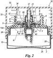
- the device for containing a fluid substance is suitable to be connected to a pump member 20 ( fig. 2 ), suitable to create in the bag 1 a depression (with respect to the room pressure) comprised between around 400 and 800 millibar, and more preferably equal to around 600 millibar.
- a pump member 20 fig. 2
- the flange 4 can be, at most, slightly curved, but substantially it is not deformed. Therefore in the present context with flexible walls it is intended walls which are completely collapsed at the above pressures created by the pump member, while with rigid flange is intended a flange which is not deformed at the above-mentioned pressures.
- connection body 60 of the ring cap element 5 further comprises at least one portion 65 of a substantially cylindrical wall, the portion 65 presenting an equal distance R1 with respect to the longitudinal symmetry axis L, wherein the wall extends beneath said annular seat 63.
- the wall comprises at least a guide element 66 comprising at least a guide portion presenting a distance R2 with respect to the longitudinal symmetry axis L different with respect to the distance R1 of the portion 65 of the substantially cylindrical wall, the guide portion being suitable to guide at least a portion of the flange 4 from a free lower edge 67 of the connection body 60 to the annular seat 63.
- substantially cylindrical wall it is intended a wall the distance R1 of which with respect to the symmetry axis L is substantially constant from the upper edge of the aforesaid wall to its lower edge.
- the lower edge of the substantially cylindrical wall has a rounded portion, but above this rounded portion, the substantially cylindrical wall has a distance R1 constant with respect to the symmetry axis L.
- the guide element 66 also comprises means 68 suitable to prevent the flange 4 from slipping out of the annular seat once it has been guided therein, so that the connection means 6 fasten stably the bag 1 to the ring cap element 5 at least with respect to vertical movements or downwards rotatory movements of said bag 1 with respect to the ring cap element 5.
- connection flange 4 is substantially rigid.
- such means 68 suitable to prevent the flange 4 from slipping out of the annular seat 63 comprise a restriction element 68 arranged inside the guide element 66 in proximity of the annular seat 63, so as to restrict the width of the guide element 66 in proximity of the annular seat 63, so as to prevent the flange 4 from entering back in the guide element 66.
- the width must remain greater than the thickness of the connection flange 4, so as not to block the insertion thereof until the annular seat 63.
- it is possible to provide other types of means suitable to prevent the flange 4 from slipping out of the annular seat 63 such as for example a closure element for closing the guide element 66.
- the guide element 66 comprises at least a lateral wall 66C, 66D at least a portion of which is inclined with respect to both the longitudinal symmetry axis L of the connection body 60, and the rest surface 64 for the flange 4 of the neck 3 of the bag 1.
- both the lateral walls 66C, 66D have at least an inclined portion with respect to both the longitudinal symmetry axis L of the connection body 60, and to the rest surface 64 for the flange 4 of the neck 3 of the bag 1, as in the example illustrated in the figures.
- This feature allows to insert easily the flange 4 in the annular seat 63 with the help of the guide element 66, maintaining a stable connection between the flange 4 and the annular seat 63.
- the guide element 66 is inclined, with respect to the rest surface 64, and extends from an inlet mouth 66A for the flange 4, provided at the free lower edge 67 of the connection body 60, to an outlet mouth 66B provided in the annular seat 63.
- Those two mouths 66A, 66B are angularly distanced from each other by an angle smaller than the half of the circumference of the substantially cylindrical wall, preferably smaller than a quarter of the circumference, and more preferably smaller than one third of the circumference of the substantially cylindrical wall.
- the guide element 66 extends from the inlet mouth 66A to the outlet mouth 66B following a substantially rectilinear path.
- a substantially rectilinear path is very advantageous for the insertion of the flange 4, in particular because this latter is rigid.
- the aforesaid inclined portion of the lateral wall 66C, 66D extends until at least one between the inlet mouth 66A and the outlet mouth 66B.
- the free lower edge 67 of the connection body 60 is substantially parallel to the rest surface 64 of the annular seat 63.
- the restriction element 68 consists in a triangular tooth which extends in the prolongation of a first lateral surface 66C of the guide element 66 towards a second lateral surface 66D.
- the first and the second lateral surface 66C, 66D of the guide element 66 have inclinations different from each other in such a way that the outlet mouth 66B results narrower with respect to the inlet mouth 66A. It is possible to provide that this feature taken alone constitutes the aforesaid means suitable to prevent the flange 4 from slipping out of the annular seat 63. In such a case, it is suitable that the width L1 ( fig.1 ) of the outlet mouth 66B is substantially equal to or slightly greater (for example 20% greater) than the thickness S of the connection flange 4.
- the second lateral wall 66D less inclined than the first one, comprises in proximity of the inlet mouth 66A a widening portion 69 so as to make the entering of the flange 4 easier.
- the inlet mouth 66A has a width L2 at least 30% greater with respect to the width L1 of the outlet mouth 66B.
- Such a widening portion 69 preferably consists in a portion of the second lateral wall 66D provided substantially perpendicular to the lower free edge 67 of the connection body 60.
- the guide element 66 is a hollow portion provided in the cylindrical wall of the connection body 60.
- the guide element 66 is delimited by a couple of elements which protrude from the same cylindrical wall.
- the presence of the guide element 66 determines the delimitation of at least one portion 65 of the cylindrical wall which presents a distance R1 substantially constant with respect to the longitudinal symmetry axis L of the connection body 60.
- the presence of more than one guide element 66 determines the delimitation of more than one portion 65 of the substantially cylindrical wall. All the portions 65 present the same distance R1 with respect to the longitudinal symmetry axis L.
- second connection means 7 suitable to stably block the connection flange 4 in the seat 63 by compression of the flange 4 against the rest surface 64 of the annular seat 63, are provided.
- connection means 7 are associated with a sheath element 8 connected to the manually operated pump member 20.
- the sheath element 8 comprises further connection means 9 for connecting said sheath element 8 to said ring cap element 5, suitable to position a portion of the pump member 20 at least one the neck 3 of the bag 1, in order to withdraw a fluid substance present in the bag 1 and feed it to the outside through a dispense stem 21 of the pump member 20.
- the ring cap element 5 is preferably provided with connection counter-means 9' which cooperate in use with the further connection means 9 of the sheath element 8, as illustrated in figure 2 .
- the device for containing a fluid substance described above is suitable to assembled in a dispense system illustrated in figure 2 .
- Such a dispense system comprises, in addition to the above device, a rigid container 10 with which the device is to be associated, wherein the rigid container 10 has a neck 10A delimiting an access opening to a cavity of the same container 10.
- the dispense system also comprises a pump member 20 connected to the sheath element 8 in a corresponding annular seat 80 and partially inserted in the neck 3 of the bag 1, and a dispense cap 30 provided with an internal sleeve 31 suitable to be connected to the dispense stem 21 of the pump member 20, in a conventional manner for the person skilled in the art.
- the internal sleeve 31 is connected to a pipe, connected on its turn to a dispense opening of the dispense cap 30, the pipe and the dispense opening are not illustrated in the figures.
- the device is connected to the external container 10 so that the bag 1 is inserted in the cavity of the external container 10. More precisely the ring cap member 5 is connected to the neck 10A of the external container 10. To this end, the ring cap element 5 is provided with connection means 5A for connecting to the neck 10A of the rigid external container 10, which on its turn is provided with connection counter-means 10B suitable to cooperate with the aforesaid connection means 5A.
- the dispense cap 30 comprises an upper wall 32, on the internal surface of which the aforesaid sleeve 31 is provided, and from which extends at least one lateral mantle 33, as well as an internal guide element 34 arranged on the internal surface of the upper wall 32, and suitable to cooperate with a guide counter-element 81 provided on the sheath element 8.
- the upper wall 32 of the dispense cap 30 has a transverse dimension greater than or equal to the transverse dimension of the rigid container 10 while the lateral mantle 33 has a length such as to cover the device for containing the fluid substance.
- the lateral mantle 33 has a length such as to cover the device for containing the fluid substance.
- a dip tube element 40 is connected to the pump member 20 and inserted inside the body 2 of the bag 1, so as to be immerged in the fluid substance to be dispensed.
- the pump member 20 is of the airless type, and is hermetically inserted in the neck 3 of the bag 1 by means of a tight member 50 inserted in an upper portion 41 of the dip tube element 40, the upper portion 41 being directly connected to the body of the pump member 20.
- a tight member 50 inserted in an upper portion 41 of the dip tube element 40, the upper portion 41 being directly connected to the body of the pump member 20.
- the rigid external container 10 can be made in any rigid material, preferably in glass or plastics.
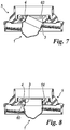
- these latter are inclined with respect to each other, so as to allow the insertion of the flange 4 in the guide element 66 and then in the annular seat 63.
- This inclination in fact, makes the insertion of the flange 4 in the guide element 66 easier, as can be seen in particular in figures 8 and 9 .
- the bag 1 and the ring cap element 5 are inclined with respect to each other ( fig. 6 ).
- the flange 4 is partially inserted in the guide element 66, in a way as to insert partially the neck 3 of the bag 1 in the annular seat 63 of the connection body 60 ( fig. 7 ).
- the insertion of the neck 3 of the bag 1 in the annular seat 63 is completed ( fig. 8 ).
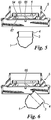
- the step of at least partial deformation of the bag 1 provides to press on the internal surface of the bottom wall 2A of the body 2 of the bag 1 in a way as to extend it. Successively one presses on at least two areas of the external surface of the lateral wall 2B of the body 2 of the bag 1 so as to reduce the lateral dimensions of the bag 1.
- a stem 100 comprising an internal through channel connected to means suitable to suction and feed air inside the bag 1.
- this stem 100 one provides to operate the aforesaid pressure on the bottom wall 2A of the bag 1 ( fig. 3 ).
- the pressure on the external surface of the lateral wall is preferably operated by a jaw device 200 ( figures 4 and 9 ) provided with at least two arms 201 provided with respective squeeze elements 202 at a free end.
- the device 200 comprises three arms 201.
- the squeeze elements 202 comprise idle wheels, so as to be able to be displaced along the lateral wall 2B of the bag during their squeezing. Doing so one can operate easily the squeezing of the lateral wall 2B of the bag 1 from the bottom wall 2A substantially until to the neck 3 ( fig. 4 ).
- the jaw device 200 is suitable to deform the portion P ( fig. 1 ) of the bag 1 immediately below the neck 3 of the bag 1.
- the stem 100 is preferably connected to means suitable to operate such decompression.
- the bag 1 after the insertion in the rigid container 10, is inflated by means of the stem 100 ( figure 11 ) .
- the sheath element 8, the pump member 20 provided with the dip tube element, and the dispense cap 30, preferably previously already mounted together, are connected to the ring cap element 5 mounted on the rigid container 10, as illustrated in fig. 12 .
Landscapes
- Engineering & Computer Science (AREA)
- Mechanical Engineering (AREA)
- Closures For Containers (AREA)
- Containers And Packaging Bodies Having A Special Means To Remove Contents (AREA)
- External Artificial Organs (AREA)
Claims (10)
- Vorrichtung zur Aufnahme einer durch eine handbetätigte Pumpe (20) auszugebenden flüssigen Substanz, die geeignet ist, dem Hals (10A) eines starren Behälters (10) zugeordnet zu werden, umfassend:- eine Tasche (1), die einen Körper (2) aufweist, der eine Bodenwand (2A) und eine Seitenwand (2B) umfasst, wobei beiden davon flexibel sind, und einen Hals (3), aus welchem ein wesentlich starrer Anschlußflansch (4) quer verläuft,- und ein Ringkappenelement (5), das erste Verbindungsmittel (6) der genannten Tasche (1) umfasst, die einen ringförmigen Verbindungskörper (60) mit einer Längssymmetrieachse (L) aufweisen, worin der ringförmige Verbindungskörper (60)- eine untere Portion (61) mit einem Durchmesser (D1), der kleiner als der Außendurchmesser (D4) des genannten Flansches (4) der Tasche (1) und größer oder gleich dem Außendurchmesser (D3) des genannten Halses (3) der Tasche (1) ist, so dass sie mindestens eine Portion des genannten Halses (3) der Tasche (1) aufnehmen kann,- und eine obere Portion (62), die einen nach oben offenen ringförmigen Sitz (63) aufweist, der eine waagerecht liegende Auflagefläche (64) für den genannten Anschlußflansch (4) aufweist,aufweist, worin der Verbindungskörper (60) mindestens eine Portion (65) einer wesentlich zylindrischen Wand weiter umfasst, wobei die ganze genannte Portion (65) denselben Abstand zu der genannten Längssymmetrieachse (L) hat, wobei die genannte Wand unterhalb des genannten ringförmigen Sitzes (63) verläuft, wobei die genannte Wand mindestens ein Führungselement (66) umfasst, das mindestens eine Führungsportion umfasst, die einen Abstand zu der Längssymmetrieachse (L) anders als der genannte Abstand (R1) der Portion (65) der wesentlich zylindrischen Wand aufweist, wobei die genannte Portion (65) geeignet ist, mindestens eine Portion des genannten Flansches (4) von einem freien unteren Rand (67) des genannten Verbindungskörpers (60) zu dem genannten ringförmigen Sitz (63) zu führen, dadurch gekennzeichnet, dass das genannte Führungselement (66) Mittel (68) umfasst, die geeignet sind zu verhindern, dass der genannte Flansch (4) aus dem genannten ringförmigen Sitz (63) herausrutscht, nachdem er darin geführt worden ist, so dass die genannten Verbindungsmittel (6) die genannte Tasche (1) an dem genannten Ringkappenelement (5) mindestens relativ zu senkrechten Bewegungen oder Drehbewegungen nach unten der genannten Tasche (1) relativ zu dem Ringkappenelement (5) stabil befestigen.
- Vorrichtung nach dem vorhergehenden Anspruch, dadurch gekennzeichnet, dass das Führungselement (66) schräg ist und von einer an dem freien unteren Rand (67) des Verbindungskörpers (60) angeordneten Einlassmündung (66BA) für der genannte Flansch (4) zu einer in dem ringförmigen Sitz (63) angeordneten Auslassmündung (66B) verläuft, und dass die beiden Mündungen (66A, 66B) des Führungselements (66) um einen Winkel von weniger als der Hälfte des Umfangs der zylindrischen Wand (65), vorzugsweise von weniger als einem Viertel des Umfangs der zylindrischen Wand (65), mehr vorzugsweise von weniger als einem Drittel des Umfangs der zylindrischen Wand (65) von einander, winkelmäßig beabstandet sind.
- Vorrichtung nach einem der vorhergehenden Ansprüche, dadurch gekennzeichnet, dass das genannte Führungselement (66) ein in der zylindrischen Wand (65) des Verbindungskörpers (60) vorhandener hohler Abschnitt ist.
- Vorrichtung nach einem der vorhergehenden Ansprüche, dadurch gekennzeichnet, dass zweite Verbindungsmittel (7) vorhanden sind, die geeignet sind, den Flansch (4) der Tasche (1) in dem ringförmigen Sitz (63) des Ringkappenelements (5) durch Pressen des Flansches (4) gegen die Auflagefläche (64) des genannten ringförmigen Sitzes (63) stabil zu sperren.
- Vorrichtung nach Anspruch 4, dadurch gekennzeichnet, dass die zweiten Verbindungsmittel (7) einem mit einem handbetätigten Pumporgan (20) verbundenen Hüllenelement (8) zugeordnet sind, und dass weitere Verbindungsmittel zur Verbindung des genannten Hüllenelements (8) mit dem genannten Ringkappenelement (5) vorhanden sind, die geeignet sind, einen Abschnitt des Pumporgans (20) mindestens in dem Hals der genannten Tasche (1) anzuordnen.
- Vorrichtung nach einem der Ansprüche 2 zu 5, dadurch gekennzeichnet, dass das Führungselement (66) eine erste Seitenwand wall (66C) und eine zweite Seitenwand (66D) aufweist, wobei die genannte erste Seitenwand und die genannte zweite Seitenwand (66C, 66D) des Führungselements (66) voneinander unterschiedliche Neigungen haben, so dass die Auslassmündung (66B) enger als die Einlassmündung (66A) ist.
- Vorrichtung nach einem der Ansprüche 2 oder 6, dadurch gekennzeichnet, dass die Auslassmündung (66B) eine Breite (L1) aufweist, die wesentlich gleich oder etwas größer als der Dicke (S) des Anschlußflansches (4) ist, wobei die zweite Seitenwand (66D) mit einem sich erweiternden Abschnitt (69) in der Nähe der Einlassmündung (66A) versehen ist, so dass die genannte Einlassmündung (66A) eine Breite (L2) aufweist, die mindestens um 30 % größer ist als die genannte Breite (L1) der genannten Auslassmündung (66B).
- Verfahren zum Zusammenbau eines Ausgabesystems, umfassend:- eine Vorrichtung nach Anspruch 1,- und einen starren Behälter (10), dem die genannte Vorrichtung zugeordnet werden soll, worin der genannte starre Behälter (10) einen eine Zugangsöffnung zu einem Hohlraum des Behälters (10) begrenzenden Hals (10A) aufweist,dadurch gekennzeichnet, dass es- einen Schritt der Bildung einer Tasche (1),- einen Schritt der mindestens teilweise Verformung der Tasche (1), um die Querabmessungen davon zu verringern,- einen Schritt der Verbindung der verformte Tasche (1) mit dem Ringkappenelement (5), so dass die genannte verformte Tasche (1) an dem genannten Ringkappenelement (5) mindestens relativ zu senkrechten Bewegungen oder Drehbewegungen nach unten der genannten Tasche (1) relativ zu dem Ringkappenelement (5) stabil befestigt wird,- und einen weiteren Schritt, der dem genannten Verbindungsschritt folgt, worin das Ringkappenelement (5) dem Hals (10A) des genannten starren Behälters (10) zugeordnet wird und gleichzeitig die verformte Tasche (1) in den genannten Hohlraum des starren Behälters (10) eingeführt wird, umfasst.
- Verfahren nach Anspruch 8, dadurch gekennzeichnet, dass, um die genannte verformte Tasche (1) dem genannten Ringkappenelement (5) zuzuordnen, werden diese zueinander geneigt, so dass der Flansch (4) in ein Führungselement (66) des Ringkappenelements (5) und dann in einen ringförmigen Sitz (63) des Ringkappenelements (5) eingeführt werden kann.
- Verfahren nach einem der Ansprüche 8 oder 9, dadurch gekennzeichnet, dass die genannte Tasche (1) aufgeblasen wird, nachdem sie in den genannten starren Behälter (10) eingeführt worden ist.
Applications Claiming Priority (1)
| Application Number | Priority Date | Filing Date | Title |
|---|---|---|---|
| ITMI20141814 | 2014-10-21 |
Publications (2)
| Publication Number | Publication Date |
|---|---|
| EP3012029A1 EP3012029A1 (de) | 2016-04-27 |
| EP3012029B1 true EP3012029B1 (de) | 2019-07-24 |
Family
ID=52130618
Family Applications (1)
| Application Number | Title | Priority Date | Filing Date |
|---|---|---|---|
| EP15190583.3A Active EP3012029B1 (de) | 2014-10-21 | 2015-10-20 | Vorrichtung zur aufnahme einer flüssigen substanz |
Country Status (4)
| Country | Link |
|---|---|
| US (1) | US10065203B2 (de) |
| EP (1) | EP3012029B1 (de) |
| CN (1) | CN105620894B (de) |
| ES (1) | ES2751453T3 (de) |
Families Citing this family (3)
| Publication number | Priority date | Publication date | Assignee | Title |
|---|---|---|---|---|
| FR3042181B1 (fr) * | 2015-10-08 | 2020-02-28 | Qualipac | Dispositif de conditionnement et distribution par dose d'un produit fluide |
| IT202000027618A1 (it) * | 2020-11-18 | 2022-05-18 | Lumson Spa | Dispositivo di erogazione di una sostanza fluida |
| US11679403B1 (en) | 2022-02-02 | 2023-06-20 | Ries Ries Inc | Travel dispenser for dispensing a fluid |
Citations (2)
| Publication number | Priority date | Publication date | Assignee | Title |
|---|---|---|---|---|
| US3420413A (en) * | 1967-08-14 | 1969-01-07 | Diamond Int Corp | Liquid and paste dispenser |
| US20090014471A1 (en) * | 2007-07-11 | 2009-01-15 | Yung Hsing Lin | Liquid dispensing device |
Family Cites Families (12)
| Publication number | Priority date | Publication date | Assignee | Title |
|---|---|---|---|---|
| JPH0575163U (ja) * | 1992-03-18 | 1993-10-12 | 凸版印刷株式会社 | 易リフィル性容器 |
| JP4212816B2 (ja) | 2002-02-28 | 2009-01-21 | 株式会社吉野工業所 | 詰め替え容器と、この詰め替え容器を装填する収納容器 |
| JP2004161287A (ja) | 2002-11-11 | 2004-06-10 | Shiseido Co Ltd | ディスペンサー容器 |
| FR2853633B1 (fr) | 2003-04-10 | 2005-09-23 | Kamaya Kagaku Kogyo Kabushiki | Double contenant avec distributeur |
| DE10335842C5 (de) * | 2003-08-05 | 2011-04-28 | Seaquist Perfect Dispensing Gmbh | Abgabepackung |
| DE102004061965B3 (de) | 2004-12-23 | 2006-06-08 | Gaplast Gmbh | Flasche |
| US20090014470A1 (en) * | 2007-07-11 | 2009-01-15 | Yung Hsing Lin | Liquid dispensing device |
| ITMI20071936A1 (it) | 2007-10-08 | 2008-01-07 | Lumson Spa | Metodo per la realizzazione di un dispositivo per contenere a tenuta d'aria e per erogare sostanze fluide e dispositivo cosi' ottenuto |
| IT1393823B1 (it) | 2009-04-20 | 2012-05-11 | Lumson Spa | Dispositivo per contenere a tenuta d'aria e per erogare sostanze fluide |
| IT1394925B1 (it) * | 2009-04-30 | 2012-07-27 | Patrini | Metodo per la realizzazione di un contenitore associabile a pompe airless |
| IT1395126B1 (it) * | 2009-07-30 | 2012-09-05 | Lumson Spa | "contenitore perfezionato associabile a pompe airless e metodo per la sua realizzazione" |
| JP5208876B2 (ja) | 2009-07-31 | 2013-06-12 | 株式会社吉野工業所 | 二重容器 |
-
2015
- 2015-10-20 ES ES15190583T patent/ES2751453T3/es active Active
- 2015-10-20 EP EP15190583.3A patent/EP3012029B1/de active Active
- 2015-10-20 US US14/887,920 patent/US10065203B2/en active Active
- 2015-10-21 CN CN201511035765.XA patent/CN105620894B/zh active Active
Patent Citations (2)
| Publication number | Priority date | Publication date | Assignee | Title |
|---|---|---|---|---|
| US3420413A (en) * | 1967-08-14 | 1969-01-07 | Diamond Int Corp | Liquid and paste dispenser |
| US20090014471A1 (en) * | 2007-07-11 | 2009-01-15 | Yung Hsing Lin | Liquid dispensing device |
Also Published As
| Publication number | Publication date |
|---|---|
| CN105620894B (zh) | 2019-06-11 |
| EP3012029A1 (de) | 2016-04-27 |
| US20160107181A1 (en) | 2016-04-21 |
| CN105620894A (zh) | 2016-06-01 |
| US10065203B2 (en) | 2018-09-04 |
| ES2751453T3 (es) | 2020-03-31 |
Similar Documents
| Publication | Publication Date | Title |
|---|---|---|
| JP5551433B2 (ja) | 液体吐出シリンジ | |
| EP3012029B1 (de) | Vorrichtung zur aufnahme einer flüssigen substanz | |
| WO2007019848A3 (en) | Device for connecting a flexible container to a beverage dispenser | |
| US20160100703A1 (en) | Universal threaded bottle cap and straw | |
| US20080035598A1 (en) | Closure Device for a Bottle | |
| US20140183229A1 (en) | Pumping device for a fluid container | |
| EP2826977B1 (de) | Vorrichtung zur zumindest teilweisen blockierung einer öffnung und zur formung einer dichtung in der öffnung | |
| US20240066537A1 (en) | Device for dispensing a fluid product, and method for filling same | |
| EP3917854B1 (de) | Belüfteter ausguss für einen flüssigkeitstank | |
| EP2583904B1 (de) | Behälter mit aufgeklappter Rückwand | |
| JP5780541B2 (ja) | 液体噴出器 | |
| WO2021059697A1 (ja) | ディスペンサー | |
| EP3305681B1 (de) | Spender vom pumpentyp | |
| JP6774081B2 (ja) | 流動物質を包含して、分配する装置 | |
| US20240131542A1 (en) | Fluid product reservoir and dispenser | |
| JP2018104053A (ja) | ポンプ付き噴出器及び液体噴出容器 | |
| JP5009038B2 (ja) | レフィル容器 | |
| KR101713048B1 (ko) | 액상 내용물의 정량 인출이 가능한 용기 | |
| JP6660830B2 (ja) | 定量吐出器 | |
| JP6012187B2 (ja) | 吐出容器 | |
| EP2639198A1 (de) | Ventil zum Ablass von Flüssigkeiten aus Behältern | |
| GB2537471A (en) | A fluid coupling | |
| WO2014199094A1 (fr) | Reservoir de produit fluide rechargeable. | |
| EP2785466A2 (de) | Pumpvorrichtung für einen flüssigkeitsbehälter | |
| JP2010274981A (ja) | ポンプ付きチューブ容器 |
Legal Events
| Date | Code | Title | Description |
|---|---|---|---|
| PUAI | Public reference made under article 153(3) epc to a published international application that has entered the european phase |
Free format text: ORIGINAL CODE: 0009012 |
|
| AK | Designated contracting states |
Kind code of ref document: A1 Designated state(s): AL AT BE BG CH CY CZ DE DK EE ES FI FR GB GR HR HU IE IS IT LI LT LU LV MC MK MT NL NO PL PT RO RS SE SI SK SM TR |
|
| AX | Request for extension of the european patent |
Extension state: BA ME |
|
| STAA | Information on the status of an ep patent application or granted ep patent |
Free format text: STATUS: REQUEST FOR EXAMINATION WAS MADE |
|
| 17P | Request for examination filed |
Effective date: 20161027 |
|
| RBV | Designated contracting states (corrected) |
Designated state(s): AL AT BE BG CH CY CZ DE DK EE ES FI FR GB GR HR HU IE IS IT LI LT LU LV MC MK MT NL NO PL PT RO RS SE SI SK SM TR |
|
| GRAP | Despatch of communication of intention to grant a patent |
Free format text: ORIGINAL CODE: EPIDOSNIGR1 |
|
| STAA | Information on the status of an ep patent application or granted ep patent |
Free format text: STATUS: GRANT OF PATENT IS INTENDED |
|
| INTG | Intention to grant announced |
Effective date: 20190222 |
|
| GRAS | Grant fee paid |
Free format text: ORIGINAL CODE: EPIDOSNIGR3 |
|
| GRAA | (expected) grant |
Free format text: ORIGINAL CODE: 0009210 |
|
| STAA | Information on the status of an ep patent application or granted ep patent |
Free format text: STATUS: THE PATENT HAS BEEN GRANTED |
|
| AK | Designated contracting states |
Kind code of ref document: B1 Designated state(s): AL AT BE BG CH CY CZ DE DK EE ES FI FR GB GR HR HU IE IS IT LI LT LU LV MC MK MT NL NO PL PT RO RS SE SI SK SM TR |
|
| REG | Reference to a national code |
Ref country code: GB Ref legal event code: FG4D |
|
| REG | Reference to a national code |
Ref country code: CH Ref legal event code: EP |
|
| REG | Reference to a national code |
Ref country code: DE Ref legal event code: R096 Ref document number: 602015034190 Country of ref document: DE |
|
| REG | Reference to a national code |
Ref country code: AT Ref legal event code: REF Ref document number: 1157575 Country of ref document: AT Kind code of ref document: T Effective date: 20190815 |
|
| REG | Reference to a national code |
Ref country code: IE Ref legal event code: FG4D |
|
| REG | Reference to a national code |
Ref country code: CH Ref legal event code: NV Representative=s name: TROESCH SCHEIDEGGER WERNER AG, CH |
|
| REG | Reference to a national code |
Ref country code: NL Ref legal event code: MP Effective date: 20190724 |
|
| REG | Reference to a national code |
Ref country code: LT Ref legal event code: MG4D |
|
| REG | Reference to a national code |
Ref country code: AT Ref legal event code: MK05 Ref document number: 1157575 Country of ref document: AT Kind code of ref document: T Effective date: 20190724 |
|
| PG25 | Lapsed in a contracting state [announced via postgrant information from national office to epo] |
Ref country code: NO Free format text: LAPSE BECAUSE OF FAILURE TO SUBMIT A TRANSLATION OF THE DESCRIPTION OR TO PAY THE FEE WITHIN THE PRESCRIBED TIME-LIMIT Effective date: 20191024 Ref country code: BG Free format text: LAPSE BECAUSE OF FAILURE TO SUBMIT A TRANSLATION OF THE DESCRIPTION OR TO PAY THE FEE WITHIN THE PRESCRIBED TIME-LIMIT Effective date: 20191024 Ref country code: PT Free format text: LAPSE BECAUSE OF FAILURE TO SUBMIT A TRANSLATION OF THE DESCRIPTION OR TO PAY THE FEE WITHIN THE PRESCRIBED TIME-LIMIT Effective date: 20191125 Ref country code: NL Free format text: LAPSE BECAUSE OF FAILURE TO SUBMIT A TRANSLATION OF THE DESCRIPTION OR TO PAY THE FEE WITHIN THE PRESCRIBED TIME-LIMIT Effective date: 20190724 Ref country code: LT Free format text: LAPSE BECAUSE OF FAILURE TO SUBMIT A TRANSLATION OF THE DESCRIPTION OR TO PAY THE FEE WITHIN THE PRESCRIBED TIME-LIMIT Effective date: 20190724 Ref country code: HR Free format text: LAPSE BECAUSE OF FAILURE TO SUBMIT A TRANSLATION OF THE DESCRIPTION OR TO PAY THE FEE WITHIN THE PRESCRIBED TIME-LIMIT Effective date: 20190724 Ref country code: AT Free format text: LAPSE BECAUSE OF FAILURE TO SUBMIT A TRANSLATION OF THE DESCRIPTION OR TO PAY THE FEE WITHIN THE PRESCRIBED TIME-LIMIT Effective date: 20190724 Ref country code: SE Free format text: LAPSE BECAUSE OF FAILURE TO SUBMIT A TRANSLATION OF THE DESCRIPTION OR TO PAY THE FEE WITHIN THE PRESCRIBED TIME-LIMIT Effective date: 20190724 Ref country code: FI Free format text: LAPSE BECAUSE OF FAILURE TO SUBMIT A TRANSLATION OF THE DESCRIPTION OR TO PAY THE FEE WITHIN THE PRESCRIBED TIME-LIMIT Effective date: 20190724 |
|
| PG25 | Lapsed in a contracting state [announced via postgrant information from national office to epo] |
Ref country code: AL Free format text: LAPSE BECAUSE OF FAILURE TO SUBMIT A TRANSLATION OF THE DESCRIPTION OR TO PAY THE FEE WITHIN THE PRESCRIBED TIME-LIMIT Effective date: 20190724 Ref country code: GR Free format text: LAPSE BECAUSE OF FAILURE TO SUBMIT A TRANSLATION OF THE DESCRIPTION OR TO PAY THE FEE WITHIN THE PRESCRIBED TIME-LIMIT Effective date: 20191025 Ref country code: IS Free format text: LAPSE BECAUSE OF FAILURE TO SUBMIT A TRANSLATION OF THE DESCRIPTION OR TO PAY THE FEE WITHIN THE PRESCRIBED TIME-LIMIT Effective date: 20191124 Ref country code: RS Free format text: LAPSE BECAUSE OF FAILURE TO SUBMIT A TRANSLATION OF THE DESCRIPTION OR TO PAY THE FEE WITHIN THE PRESCRIBED TIME-LIMIT Effective date: 20190724 Ref country code: LV Free format text: LAPSE BECAUSE OF FAILURE TO SUBMIT A TRANSLATION OF THE DESCRIPTION OR TO PAY THE FEE WITHIN THE PRESCRIBED TIME-LIMIT Effective date: 20190724 |
|
| PG25 | Lapsed in a contracting state [announced via postgrant information from national office to epo] |
Ref country code: TR Free format text: LAPSE BECAUSE OF FAILURE TO SUBMIT A TRANSLATION OF THE DESCRIPTION OR TO PAY THE FEE WITHIN THE PRESCRIBED TIME-LIMIT Effective date: 20190724 |
|
| REG | Reference to a national code |
Ref country code: ES Ref legal event code: FG2A Ref document number: 2751453 Country of ref document: ES Kind code of ref document: T3 Effective date: 20200331 |
|
| PG25 | Lapsed in a contracting state [announced via postgrant information from national office to epo] |
Ref country code: RO Free format text: LAPSE BECAUSE OF FAILURE TO SUBMIT A TRANSLATION OF THE DESCRIPTION OR TO PAY THE FEE WITHIN THE PRESCRIBED TIME-LIMIT Effective date: 20190724 Ref country code: EE Free format text: LAPSE BECAUSE OF FAILURE TO SUBMIT A TRANSLATION OF THE DESCRIPTION OR TO PAY THE FEE WITHIN THE PRESCRIBED TIME-LIMIT Effective date: 20190724 Ref country code: DK Free format text: LAPSE BECAUSE OF FAILURE TO SUBMIT A TRANSLATION OF THE DESCRIPTION OR TO PAY THE FEE WITHIN THE PRESCRIBED TIME-LIMIT Effective date: 20190724 Ref country code: PL Free format text: LAPSE BECAUSE OF FAILURE TO SUBMIT A TRANSLATION OF THE DESCRIPTION OR TO PAY THE FEE WITHIN THE PRESCRIBED TIME-LIMIT Effective date: 20190724 |
|
| PG25 | Lapsed in a contracting state [announced via postgrant information from national office to epo] |
Ref country code: CZ Free format text: LAPSE BECAUSE OF FAILURE TO SUBMIT A TRANSLATION OF THE DESCRIPTION OR TO PAY THE FEE WITHIN THE PRESCRIBED TIME-LIMIT Effective date: 20190724 Ref country code: SK Free format text: LAPSE BECAUSE OF FAILURE TO SUBMIT A TRANSLATION OF THE DESCRIPTION OR TO PAY THE FEE WITHIN THE PRESCRIBED TIME-LIMIT Effective date: 20190724 Ref country code: MC Free format text: LAPSE BECAUSE OF FAILURE TO SUBMIT A TRANSLATION OF THE DESCRIPTION OR TO PAY THE FEE WITHIN THE PRESCRIBED TIME-LIMIT Effective date: 20190724 Ref country code: SM Free format text: LAPSE BECAUSE OF FAILURE TO SUBMIT A TRANSLATION OF THE DESCRIPTION OR TO PAY THE FEE WITHIN THE PRESCRIBED TIME-LIMIT Effective date: 20190724 Ref country code: IS Free format text: LAPSE BECAUSE OF FAILURE TO SUBMIT A TRANSLATION OF THE DESCRIPTION OR TO PAY THE FEE WITHIN THE PRESCRIBED TIME-LIMIT Effective date: 20200224 |
|
| REG | Reference to a national code |
Ref country code: DE Ref legal event code: R097 Ref document number: 602015034190 Country of ref document: DE |
|
| PLBE | No opposition filed within time limit |
Free format text: ORIGINAL CODE: 0009261 |
|
| STAA | Information on the status of an ep patent application or granted ep patent |
Free format text: STATUS: NO OPPOSITION FILED WITHIN TIME LIMIT |
|
| PG2D | Information on lapse in contracting state deleted |
Ref country code: IS |
|
| PG25 | Lapsed in a contracting state [announced via postgrant information from national office to epo] |
Ref country code: LU Free format text: LAPSE BECAUSE OF NON-PAYMENT OF DUE FEES Effective date: 20191020 |
|
| 26N | No opposition filed |
Effective date: 20200603 |
|
| REG | Reference to a national code |
Ref country code: BE Ref legal event code: MM Effective date: 20191031 |
|
| PG25 | Lapsed in a contracting state [announced via postgrant information from national office to epo] |
Ref country code: SI Free format text: LAPSE BECAUSE OF FAILURE TO SUBMIT A TRANSLATION OF THE DESCRIPTION OR TO PAY THE FEE WITHIN THE PRESCRIBED TIME-LIMIT Effective date: 20190724 Ref country code: BE Free format text: LAPSE BECAUSE OF NON-PAYMENT OF DUE FEES Effective date: 20191031 |
|
| PG25 | Lapsed in a contracting state [announced via postgrant information from national office to epo] |
Ref country code: IE Free format text: LAPSE BECAUSE OF NON-PAYMENT OF DUE FEES Effective date: 20191020 |
|
| PG25 | Lapsed in a contracting state [announced via postgrant information from national office to epo] |
Ref country code: CY Free format text: LAPSE BECAUSE OF FAILURE TO SUBMIT A TRANSLATION OF THE DESCRIPTION OR TO PAY THE FEE WITHIN THE PRESCRIBED TIME-LIMIT Effective date: 20190724 |
|
| PG25 | Lapsed in a contracting state [announced via postgrant information from national office to epo] |
Ref country code: MT Free format text: LAPSE BECAUSE OF FAILURE TO SUBMIT A TRANSLATION OF THE DESCRIPTION OR TO PAY THE FEE WITHIN THE PRESCRIBED TIME-LIMIT Effective date: 20190724 Ref country code: HU Free format text: LAPSE BECAUSE OF FAILURE TO SUBMIT A TRANSLATION OF THE DESCRIPTION OR TO PAY THE FEE WITHIN THE PRESCRIBED TIME-LIMIT; INVALID AB INITIO Effective date: 20151020 |
|
| PG25 | Lapsed in a contracting state [announced via postgrant information from national office to epo] |
Ref country code: MK Free format text: LAPSE BECAUSE OF FAILURE TO SUBMIT A TRANSLATION OF THE DESCRIPTION OR TO PAY THE FEE WITHIN THE PRESCRIBED TIME-LIMIT Effective date: 20190724 |
|
| P01 | Opt-out of the competence of the unified patent court (upc) registered |
Effective date: 20230626 |
|
| PGFP | Annual fee paid to national office [announced via postgrant information from national office to epo] |
Ref country code: IT Payment date: 20230921 Year of fee payment: 9 |
|
| PGFP | Annual fee paid to national office [announced via postgrant information from national office to epo] |
Ref country code: GB Payment date: 20231025 Year of fee payment: 9 |
|
| PGFP | Annual fee paid to national office [announced via postgrant information from national office to epo] |
Ref country code: ES Payment date: 20231102 Year of fee payment: 9 |
|
| PGFP | Annual fee paid to national office [announced via postgrant information from national office to epo] |
Ref country code: FR Payment date: 20231025 Year of fee payment: 9 Ref country code: DE Payment date: 20231018 Year of fee payment: 9 Ref country code: CH Payment date: 20231102 Year of fee payment: 9 |